rs232rs485转换器使用说明书
RS232 RS485 串口服务器 说明书
RS232/RS485串口服务器说明书(Ver3.3)关于配置串口服务器的更详细信息(如配置运行参数、透明传输、编程接口等),请查看光盘里的《串口服务器技术配置手册》及相关配置视频演示。
一、产品说明 (3)1、串口服务器介绍 (3)2、型号说明 (4)1. 商用级串口服务器 (4)2. 工业级串口服务器 (4)二、串口服务器使用及配置 (5)1、快速安装 (5)1. 最小系统需求 (5)2. 安装串口服务器 (5)3. 检查串口服务器运行状态 (6)4. 恢复出厂值 (7)5. 安装使用虚拟串口软件 (7)6. RS232串口服务器接线方法 (11)7. RS485串口服务器接线方法 (11)8. RS232+RS485串口服务器接线方法 (12)2、网络参数设置 (13)3、配置串口服务器 (14)4、扩展电源输出 (14)5、RS485总线组网注意事项 (15)6、Server、Client、UDP广播工作模式说明 (16)7、注意事项 (17)8、免责声明 (17)三、保修服务及技术支持 (18)1、免费保修 (18)2、免费保修服务方式 (18)3、不属于免费保修的情况 (19)4、软件升级及技术支持网址 (19)一、一、 产品说明产品说明串口服务器介绍1、串口服务器介绍采用16C554作为串口扩展芯片,提供1-16路硬件独立串口。
支持TCP/IP Server、Client及UDP广播模式。
支持网关,TCP/IP模式下可以跨网段访问。
支持双(多)串口服务器透明传输功能。
串口支持流传输及自适应数据帧模式,兼容各种串口应用。
提供VSPM虚拟串口软件,通过智能化的搜索映射方式建立虚拟串口。
虚拟串口与串口服务器为自适应设计,虚拟串口的参数与串口服务器自动同步,无需手工设置。
同时也支持Socket编程接口,用户程序按照Sokcet标准就可以与串口服务器进行通讯。
使用Telnet通过网络进行设备管理,四口及以上设备提供一个用于RS232管理口,可以在现场进行设备管理。
UART RS232 RS485过电线通信转接器模块用户手册说明书

UART/RS232/RS485Over Powerline Communication Transceiver ModuleUser Manual.LinkSprite Technologies, IncJuly, 2008Table of ContentⅠSummary (3)1 Introduction (3)2 Features (4)3 Specifications (5)4 Applications (5)ⅡDiagram (6)1 Functional Diagram (6)2 Board Layout (6)3 LED (7)4 Definition of Pin (7)ⅢCommand Interface (8)1 Command Mode (8)1.1 Enter command mode (8)1.2 Exit command mode (8)2 Arguments and Responses (8)2.1 Arguments and Responses (8)2.2 Commands without Arguments (9)2.3 Modified arguments (9)3 Command List (10)ⅣRepeater Function (13)1 Introduction (13)2 Function Setting (14)2.1Start repeater function (14)2.2Turn off repeater function (15)2.3 Setting Illustration (15)3 Repeater Grade (15)ⅤLogic Address (17)1 Logic Address (17)2 Address Setting (18)ⅥApplication Illustration (20)ⅠSummary1. IntroductionUART/RS232/RS485 are widely used in industrial control and instrument fields. PLC-UART, PLC-RS232/RS485 transceiver modules from LinkSprite (LinkSprite modules) are transceiver modules designed to send/receiver UART/RS232/RS485 data over the powerline network.PLC-RS232/RS485 is designed to transparently move serial data over the powerline network, and achieves the target of replacing RS232/RS485 cables by the ubiquitous powerline network.LinkSprite modules have the built-in packet-level repeater function.This feature can greatly extend the coverage of the powerline communication.LinkSprite modules has both physical and logic addresses. In a network, both physical and logic addresses can be used to address different nodes in the network.2 Features●Fully transparent mode, plug and play coming out of the box withoutthe need to do any programming.● Built-in error correction codes.● Built-in repeater function to extend the coverage.●Physical and logic address●AT commands used for advanced configuration.● UART, RS232 interface and RS485 bus●FSK(Frequency Shift Keying)modulation used in physical layer● Low power● RoHS● Small module size, and easy to be implemented into existingproducts.3 SpecificationsProduct name PLC-UART/RS232/RS485Transceiver ModuleInterface UART, RS232 or RS485Operating Voltage 230VAC/50Hz,110VAC/60HzModulation FSK(Frequency Shift Keying)Carrier frequency 262K/144KHzError Correction FEC(Forward Error Correction)Data rate on Powerline 30KbpsMaximum packet data length 320bytesRepeater Hops 3 HopsTransmission distance 300 feets(no repeater)Support nodes number 65535LED Power Line Activity LEDsystem LEDserial port LED4 Applications●AMR●Industry manufacture and control●Safeguard, fire alarm, smoke alarm●Collect and transmit instrument data●Safeguard and monitor●Home automationⅡDiagram 1 Functional Diagram2 Board Layout3 LEDL1PLC LED: green mans module is sending data to PLC; red means module is receiving data from PLCL2 System LED ,green means system is in normalL3Serial port LED ,green means module is receiving data from aerial port; red means module is sending data to serial port4 Definition of Pin1 VAC 220VAC/50Hz or 110VAC/60Hz Power lines2 VAC 220VAC/50Hz or 110VAC/60Hz3 18V+ +18VDC Module power4 18V- -18VDC5 RS485 B RS485busB RS485 bus6 RS485 A RS485 bus A GND7 GNDGND8RS232TXD RS232 data transmission should link to PC’sRXDRS232 interface9RS232 RXD RS232 data receiving should link to PC’s RXDⅢCommand Interface1 Command Mode1.1 Enter command modeThe module can be put into command mode by sending “+++” through serial port. The module will respond with an “ok”. In order to prevent the situation where the user data” +++”mistakenly triggers the command mode, there must be no serial port data input one second before and after the receiving of "+++". At the same time, the gap between the three”+” should not be more than one second, otherwise, it will be considered as a data rather than a command.1.2 Exit command modeThere are two approaches to exit command mode. One way is to input command “ATEX”. The other is to timeout and automatically exit. In either case, the modules will response "exited". The timeout value can be set by command "ATTO"2 Arguments and Responses2.1 Arguments and ResponsesFor all the commands with arguments: if the parameters are correct, the module will respond with an “ok”. Otherwise, the modules will response with an “invalid para”. If there are no arguments associated with the commands, it will be treated as polling modem and the module will respond with the existing arguments residing in the module.2.2 Commands without ArgumentsThere are four commands without arguments.● + + +: enter command mode; will directly return “ok”.● ATEX: exit the command mode, return “exited”.● ATRS: software reset, will reset the module immediately, no return.● ATSR: in search for other modules on the power lines, this will return thename of the found module. Please wait for two seconds after sending a command. The name of module received in two seconds will be shown in the serial port, otherwise, the name received after two seconds will be ignored. Note: In the course of searching, all bytes input from serial port also will also be ignored.2.3 Modified argumentsExcept for serial arguments, the modified arguments will be immediately saved into eeprom and take effect. The serial arguments won’t take effect immediately after being modified to avoid user from modifying PC serial arguments before inputting command. Serial arguments will take effect through automatically resetting module when exiting the command mode.3 Command ListCommand Description Arguments Description DefaultControl Class+++ none Enter commandmodeATEX Exit none Exit command modeATTO Time out 1-30Timeout value,unit: second5 ATRS Reset none Software resetNetwork classATDA DomainAddress1-32767Domain Address ofLogic Address1ATNANodeAddress1-65535Node Address oflogical address1Function classATRP Repeater Y,N Relay function, Y ison, N for offYATNM NameA stringwith lengthless than 15Set the name of themodulePU-R485A Communication classATBD Baud Rate 1200, 2400,4800, 9600,19200Baud Rate 9600ATDB Data Bit 5,6,7,8 Data bit 8ATPA Parity N, O, E Parity bit,N = no, O= odd, E = evenNATST Stop Bit 1,2 Stop bit 1Debug classATRW Raw Y,NThe raw data for debugging. Themodule will outputsent raw packetsfrom host to the module, and not justthe payload. Ymeans turn on this function, N meansturning off.NATMI MIOpattern Y,N Support compatibleissue with ArianeMIO-RS232 format.The header of thedata package will be"A3 04".NATSR Search noneSearch for peer module on the power line networkⅣRepeater Function1 IntroductionTo extend the coverage, Linksprite modules have built-in repeater function.When the module's repeater function is turned on (ON is the default setting), the module echos the data packet from the power line, while entertaining the data sent by host through the serial port.Transceiver function is not influenced by repeater function, that is to say, each module can be used as a separate repeater or can be seen as repeater when sending and receiving data. It can not only send and receive data from the power line, but also repeat other data packets.In order to prevent network congestion, the module is smart enough to know the data were sent or repeated by itself and will discard the datapackets when receiving the duplicated ones.Note: Due to the fact that repeaters will resent the received data packets, if the number of repeater is too large, a number of repeaters will seize the channel, and lead to increased communication time. When deploying the repeater, one should take full account of the balance of reliability and real-time.2 Function SettingAT command ‘ATRP’ is designed to set up the repeater function.2.1Turn on repeater functionSteps input response description1 +++ ok Enter command mode2 ATRP Y or N Poll current repeater status, Y is on,N for off3 ATRP Y ok Turn on repeater function4 ATRP Y Check present repeat status, ON5 ATEX exit Exit command mode2.2Turn off repeater functionsteps input response description1 +++ ok Enter command mode2ATRPY or NCheck current repeater status, Y is on, N for off3 ATRP N okTurn off repeater function4 ATRP N Check current repeater status, OFF 5ATEXexitExit command mode2.3 Setting Illustration●Repeater function is available in the factory.●Once repeater function is modified; it will immediately take effect and be preserved permanently, even if the module is restarted.3 Repeater HopsA data packet could at most pass through third repeater three times. It is shown as follows :Data packet is sent from module A to module B. From module B to module C is the first time, to module D is the second time, and to module E is the third time. Module F is the termination. Therefore, data packet won’t be sent to module F.ⅤLogic Address1 Logic AddressModule data packets are transmitted in the way of broadcasting in power lines. All modules will receive the data packets issued by the module and sent them, through the serial port under carrier signals area.When multiple modules are installed on the same power line network, however, one does not want them to communicate directly; thus, the networks can be addressed by the logic address.Logic address is composed of two parts: domain and nodes. For example, the logic address (10:200) means that the domain value is 10, node value is 200. Logic address is the default setting (1:1).Module data packets can only be received and processed by the module at the same domain. Other modules, even detecting the carrier signal will not receive, nor to transmit to the serial port or repeater.On the above figure, A, E are at the same network, their domain values are 1; B, D, F, H are at the same network, its domain values are10;C, G are at the same network, their domain values are 2002. Although in the physically speaking, all the modules are in a power line network, the packet issued by A, will only be received and processed by E, other modules will not respond. Similarly, packet issued by F, only B, D, H will receive and process packet issued by F, other modules will not work.2 Address Settingstep input response description1 +++ ok Enter command mode2 ATDA 1-32767 Check domain values of presentlogic address. Default factory settingis 1.3 ATNA 1-65535 Check nodes values of present logicaddress. Default factory setting is 1.4 ATDA 2 ok Set domain value of logic address as25 ATNA 45 ok Set nodes of logic address as 456 ATDA 2 Check domain values of logicaddress7 ATNA 45 Check node values of logic address8 ATEX exited Exit command modeⅥApplication IllustrationIntelligent instruments widely adopt RS485 bus to communicate. For example, the power meter automatic meter reading systems, data concentrator through the RS485 bus read the message from power meter.In order to automatically meter reading, RS485 bus needs to be deployed. Here, using PU-R485A module, one can use the existed power lines to directly complete data transmission.LinkSprite Technolgies, Inc. 1410 Cannon Mountain Dr. Longmont, CO 80503 (Voice) 720-949-4-932 (Email)******************** 。
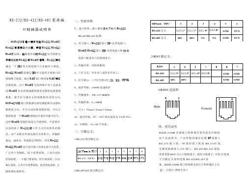
(完整版)RS-232转RS-485转换器使用说明书
RS-232/RS-485转换器使用说明书一、产品介绍HEXIN-III型转换器是RS-232与RS-485之间的双向接口的转换器、应用于主控机之间,主控机与单片机或外设之间构成点到点,点到多点远程多机通讯网络,实现多机应答通讯,广泛地应用于工业自动化控制系统、一卡通、门禁系统、停车场系统、自助银行系统、公共汽车收费系统。
饭堂售饭系统、公司员工出勤管理系统、公路收费站系统等等。
HEXIN-III型转换器、能够将RS-232串行口的TXD和RXD信号转换成两线平衡半双工的RS-485信号。
无需未接外接电源,可直接从RS-232端口的3脚窃电,同时由7脚请求发送(RTS),4脚数据终端准备好(DTR)给HEXIN-III 辅助供电,自动的流控使你不必重新设置,硬件与安装使用非常简单。
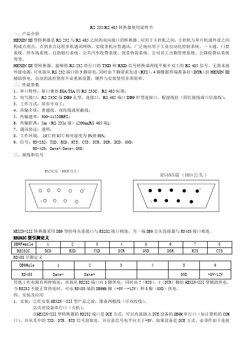
二、性能参数1、串口特性:接口兼容EIA/TIA的RS-232C,RS-485标准;2、电气接口:RS-232C端DB9孔型、连接口,RS-485端口DB9针型连接口、配接线柱(四位接线或六位接线);3、工作方式:异步半双工;4、传输介质:普通线、双绞线或屏蔽线;5、传输速率:300~11520BPS;6、传输距离:5m(RS-232c端)1200m(RS-485端);7、通讯协议:透明;8、工作环境:-10℃到85℃相对湿度为5%到95%;9、信号:RS-232:TXD、RXD、RTS、CTS、DTR、DSR、DCD、GND;RS-485:Date+/Date-,GND;三、接线和信号HEXIN-III转换器采用DB9型的母头连接口与RS232接口相连,另一端DB9公头连接器与RS485接口相连。
RS232C型引脚定义DB9Femsle 1 2 3 4 5 6 7 8RS232C DCD RXD TXD DTR GND DSR RTS CTS RS485引脚定义DB9Msle 1 2 3 4 5 6 RS485 Date- Date+ GND +5V-12V其他工作电源有两种情况:直接从RS232端口向3脚供电,同时由7(RTS)、4(DTR)脚给HEXIN-III型辅助供电,当RS232不能正常供电时,可由RS485端的DB9M6脚(+5V―+12V)和5脚(GND)供电。
R232与RS485转换器 解码器说明书
摄像机及云镜控制解码器的安装说明:1.设备概述本解码器是与安防监控系统设备配套使用的一种前端控制设备,可控制室内外云台,电动变焦镜头,一体化摄像机,灯光或雨刷。
支持RS-232和RS-485两种通讯接口,兼容多种控制协议。
其款式多样,外型设计美观大方,且具有超强的防雷、抗死机性能,性价比极高,是各款数字硬盘录像系统及矩阵系统最理想的配套设备。
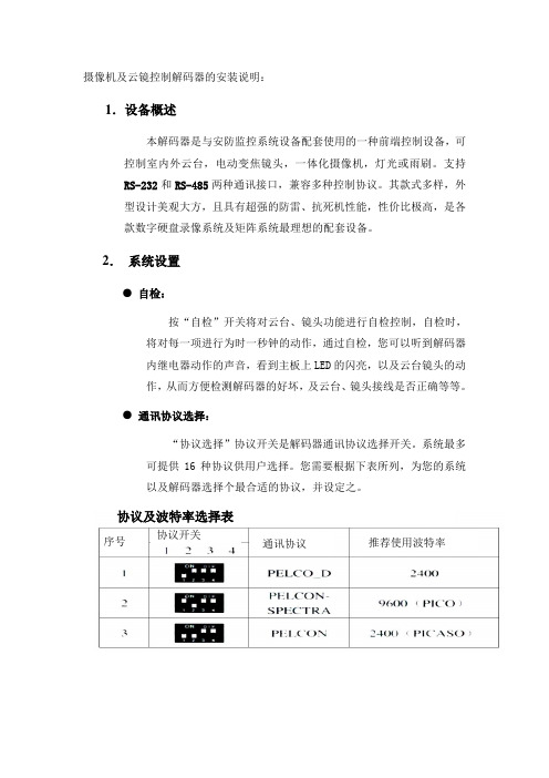
2.系统设置●自检:按“自检”开关将对云台、镜头功能进行自检控制,自检时,将对每一项进行为时一秒钟的动作,通过自检,您可以听到解码器内继电器动作的声音,看到主板上LED的闪亮,以及云台镜头的动作,从而方便检测解码器的好坏,及云台、镜头接线是否正确等等。
●通讯协议选择:“协议选择”协议开关是解码器通讯协议选择开关。
系统最多可提供16种协议供用户选择。
您需要根据下表所列,为您的系统以及解码器选择个最合适的协议,并设定之。
协议及波特率选择表序号协议开关通讯协议推荐使用波特率注:a) 协议选择不正确,解码器无法正常工作。
故请阁下您务必仔细阅读此说明书,确保您设置正确。
(本项目统一使用PELCO-D协议,波特率使用9600)b)如果系统无上表所列之协议,将协议逐一试之,或者通知经销商,我们将根据系统,及时给出新的合用的通讯协议。
3.连接示意图:解码器采用RS485通讯方式的,“A”和“B”为信号接线端,“GND”为为屏蔽地,且“A”接RS485设备接口的正端,“B”接RS485设备接口的负端。
标准RS485设备至解码器之间采用二芯屏蔽双绞线相连,连接电缆的最远累加距离不超过1500米。
多个解码器连接应在最远一个解码器的数据线两端之间并接一个120欧的匹配电阻或将解码器“终结开关”短接。
●波特率选择:波特率的选择是为了使解码器与控制设备之间有相同的数据与速度。
波特率选择不正确,解码器将无法正常工作。
波特率选择如下表:(本次系统波特率统一设置为9600)在本解码板中,每一种协议均有自己的通讯速率(波特率),您必须按照上表,将您系统和解码板的波特率设置正确。
USB TO RS232 485 TTL 用户手册说明书
USB TO RS232/485/TTL用户手册产品概述简介USB TO RS232/485/TTL是一款工业级USB转RS232/485/TTL隔离型转换器,采用原装FT232RL,内置电源隔离、ADI磁耦隔离和TVS等保护电路,铝合金外壳设计。
USB TO RS232/485/TTL操作简单,零延时自动收发转换,具有通信速度快、稳定、可靠、安全等特点,可适用于各种通信要求较高的工控设备或应用。
产品特性⚫支持USB转RS232、USB转RS485、USB转TTL(UART)通信⚫采用原装FT232RL,高速通信稳定、可靠、兼容性好⚫板载一体式电源隔离,可提供稳定的隔离电压,隔离端无须额外供电⚫板载一体式ADI磁耦隔离,可进行信号隔离,可靠性高、抗干扰强、功耗低⚫板载TVS(瞬态电压抑制管),可有效抑制电路中的浪涌电压和瞬态尖峰电压,防雷防静电⚫板载自恢复保险丝和保护二极管,可确保电流和电压稳定输出,防过流过压,抗冲击能力强⚫板载零延时自动收发转换电路,确保USB端与不同接口能快速稳定通信、互不干扰⚫板载TTL串口3.3V和5V电平转换电路,用户可通过开关切换TTL通信电平⚫铝合金外壳,氧化磨砂处理,CNC数控开孔,牢固耐用、工艺精美⚫外置3个LED指示灯,方便查看电源和信号收发状态⚫高品质USB-B和RS232接口材料,插拔顺畅,坚固可靠产品参数⚫产品类型:工业级光电隔离型转换器⚫通信速率:300-921600bps⚫主机接口:USB⚫设备接口: RS485/RS232/TTL⚫USB接口:◼工作电平:5V◼接口形式:USB-B型接口◼接口保护:200mA自恢复保险丝,隔离输出◼传输距离:约5米⚫RS485接口:◼接口形式:接线端子◼接口引脚:A+、B-、GND◼方向控制:硬件自动判别和控制数据传输方向◼接口保护:提供600W防雷、浪涌和15KV静电保护(预留120R平衡电阻焊盘) ◼传输距离:约1200米◼传输模式:点对多(至多32个节点,16个节点以上建议加中继器)⚫RS232接口:◼接口形式:DR9 公口◼接口保护:TVS管保护,浪涌和静电保护◼传输距离:约15米◼传输模式:点对点◼TTL(UART)接口:◼工作电平:3.3V或5V◼接口形式:接线端子◼接口引脚:TXD、RXD、GND◼接口保护:提供钳位保护二极管,防过压负压,抗冲击干扰◼传输模式:点对点⚫指示灯:◼PWR:电源指示灯,接入USB,检测到电压则亮红灯◼TXD:发送指示灯,有数据从USB口发出时亮绿灯◼RXD:接收指示灯,有数据从设备接口发回时亮蓝灯⚫使用环境:◼温度范围:-15℃~ 70℃◼湿度范围:5%RH ~ 95%RH⚫操作系统:Windows 10 / 8.1 / 8 / 7 / XP备注:RS485(板载预留120R平衡电阻焊盘,客户可以根据通讯数量考虑是否加入,建议在起止端加入也就是主机和最后一个设备上面各加一个120Ω的匹配电阻。
Papouch UC485 RS232到RS485 422线转换器说明书

9/30/2016w w w .p a p o u c h .c o m0004RS232 <> RS485/422UC485RS232 to RS485 or RS422 line converterwith isolationUC485 Papouch s.r.o.Page 2U C 485DatasheetCreated: 5/4/2005 Last update: 5/19/2005 9:15Number of pages: 16 © 2016 Papouch s.r.o.P a p o u c h s.r.o.Address:Strasnicka 3164 110 00 Prague 10 Czech RepublicTel:+420 267 314 267Fax:+420 267 314 269Internet:E-mail:****************Papouch s.r.o.UC485Page 3TABLE OF CONTENTSDescription .......................................................... 4 Features ............................................................. 4 Installing options ................................................. 4 Technical Parameters .. (5)General ........................................................ 5 Connector pins ............................................. 5 Settings (6)Modes .......................................................... 6 Line termination and idle mode .................... 7 Automatic control settings ............................ 7 Installation for the RS485/422 line ............... 9 Installation for the RS422 line .................... 11 RS232 line extension ................................. 12 RS485 and RS422 lines .................................... 13 Possible problems during installation . (15)Fig. 1 –Principal diagram of isolationUC485 Papouch s.r.o.Page 4DESCRIPTIONThe UC485 module converts an RS232 line to RS485 or RS422. The module settings can be set with the aid of switches, as described below. The green LED indicates that the module is ON; the yellow indicators show the RxD and TxD status.FEATURES∙Lines can be set: RS485, RS422, and RS422 multimaster∙Transmission speed up to 480 kBd∙Direction control on the RS485 line can be automatic or by DTR signal (whose polarity can be set)∙The RS485/422 line (including the grounding) is completely isolated from RS232 and from the power supply (this isolation is provided as standard for all types) ∙Optionally, grounding of the power supply and grounding of the RS232 line can be isolated from each other∙The RS485/RS422 line is over voltage protected∙The ON and data flow statuses are indicated by LED indicators – the unit activation is easy ∙ A built-in optional termination, including resistors which define the line's idle status∙Power supply 7 to 40 V (depending on the type, also 36 to 75 V or 5 V)∙D-SUB 9 connectors or a slip-on termination board∙Dimensions 105 × 55 × 24 mm, optionally secured to a DIN stripINSTALLING OPTIONSHolder:∙Without a DIN rail holder (standard)∙With a DIN rail holder RS485/422 connection:∙D-SUB 9M (type UC485C)∙Slip-on terminal board (type UC485S)Power supply:∙7 to 40 V 1(standard configuration)∙ 5 V ±10% 1,2∙ 4.5 V ±10% 2,3∙9 V ±10% 2.3∙18 V to 36 V 2.3∙36 V to 75 V 2.3Please do not hesitate to contact us if you have specific requirements for the UC485 module's configuration and functionality.1 The RS485/422 line (including the grounding) is completely conductively separated from RS232 and from thepower supply (G1 separation cf. Fig. 1). The power supply and the RS232 line have common grounding.2 The time limit for delivery of this configuration is between one and three weeks.3 The RS232 line's grounding is conductively separated from the power supply's grounding (cf. Fig. 1 to seethe G2 separation).Fig. 2 – UC485SPapouch s.r.o.UC485Page 5TECHNICAL PARAMETERSG e n e r a lPower supply voltage ........................ 7 V to 40 V (optionally, 4.5 – 75 V) with protection frompolarity reversal Power supply connector .................... S lip-on connector board Isolation ............................................. 1,000 V Maximum transmission speed ........... 480 kBd Operating temperature....................... –20 °C to +70 °C RS485/422:Terminal resistors .............................. 120 Ω Resistors which define the idle status ......... 680 Ω Maximum number of connected devices . (31)Voltage overprotection ....................... y es, 12 V bipolar transil diodes UC485C connection .......................... D -SUB 9MUC485S ............................................. s lip-on connector board RS232:Voltage overprotection ....................... 15 kV Connection ........................................ D -SUB 9M C o n n e c t o r p i n s16Fig. 3 – RS232 pinsFig. 4 - RS485/422 pins on UC485CFig. 5 – Power supply connector Fig. 6 – RS485/422 pins on UC485SUC485 Papouch s.r.o. SETTINGSM o d e sThe communication modes are set by switches on the front panel.Fig. 7 – Front panel switches, module UC485 (they are all OFF in this figure)Table 1 – Settings of the communication line modesPage Papouch s.r.o.UC485Page 7L i n e t e r m i n a t i o n a n d i d l e m o d e TERM485This device connects the impedance termination of the RS485 or RS422 line on the transmitter's side. It prevents signal from reflection at the line ends. These resistors should be connected at both ends of the communication line.TERM422This device connects the impedance termination of the RS422 line on the receiver's side. It prevents signal from reflection at the line ends. These resistors should be connected at both ends of the communication line.BIAS485This device connects the resistors which define the idle mode of the RS485 or RS422 line on the transmitter's side. They determine the idle-status levels of the communication line. (More detailed information can be found in the section "Idle mode" on page 10.)A u t o m a t i c c o n t r o l s e t t i n g sWhen automatic (time) control is used for the RS485 or RS422 line, the value T of the time delay can be set, for which the driver remains switched to transmission.Fig. 8 – Time delay for which the driver remains switched to transmissionThe default value of this delay is 460 μs; it can be changed using jumpers inside of the module. First open the module case. Unscrew the two screws (opposite to each other) on the modulecase's bottom side, loosen the screws on the top lid, and tilt the top lid out.Fig. 9 – Locations of the screws securing the top lidUC485Papouch s.r.o.Page 8There are four jumpers inside.Fig. 10 – Jumpers for setting the time delay valueThe jumpers' configuration defines the time delay value T. The default value of this delay is 460 μs; it can be changed using jumpers inside of the module. The configurations and their meanings are shown in the Table below.Table 2 – Time delay value settingSW1 SW2 SW3 SW4Papouch s.r.o.UC485I n s t a l l a t i o n f o r t h e R S485/422l i n eThe following steps are used for the UC485 converter installation for communication on an RS485 line:1) Set the switches SW3 through SW8 according to Table 1 on page 6.2) Connect the RS485 wires to the D-SUB 9M connector according to Table 3. (Cf. theconnector diagram on page 5.)Table 3 – RS485 line connection3) Connect the RS232 wires to the D-SUB 9F connector according to Table 4 using anuncrossed cable.Table 4 – RS485 line connection4) If the converter is at a line endpoint, the termination resistors should to be connected bya TERM485. Switches consider connection of resistors which define the idle status.5) Connect to the power supply.1The DTR or RTS signal is only used within modes with the DTR line control. The mode settings are described on page 6 under "Modes". Page 9UC485Papouch s.r.o.Page 10Idle modeWhen communicating on the RS485 line or the RS422 multimaster line, there may be a no-transmission status (all lines are in the receiving mode). In this case, the status of the line is undefined and it is extremely sensitive to any induced voltage (interference), which is deemed incoming signals. Therefore an idle mode should be defined by connecting suitable resistors to a line. If the line is long, the best point is at the UC485 end-of-line modules or equipment.With the UC485 converter, built-in resistors can be used, connected by the BIAS485 switches; or the resistors may be connected directly to the RS485 connector (cf. Fig. 11). For long lines, the resistor values should be higher and the termination should be connected simultaneously.SGND can also be used for connection of the cable shielding contact.Fig. 11 – Connection of resistors which define the idle modeI n s t a l l a t i o n f o r t h e R S422l i n eThe following steps are used for the UC485 converter installation for communication between two devices on an RS422 line:1) Set the switches SW3 through SW8 according to Table 1 on page 6.2) Connect the RS422 leads to the D-SUB 9M connector according to Table 5 (a drawing ofthe connectors is on page 5).Table 5 – RS422 line connection3) Connect the RS232 leads to the D-SUB 9F connector according to Table 6 using anuncrossed cable.Table 6 – RS232 line connection4) If the converter is at a line endpoint, the termination resistors are to be connected by theTERM422. For the multimaster mode, consider connection of resistors which define the idle status.5) Connect to the power supply.5The DTR or RTS signal is only used within modes with the DTR line control. The mode settings are described on page 6 under "Modes".R S232l i n e e x t e n s i o nBy using two UC485, you can extend an RS232 line to a distance of up to 1,200 m.61) Connect the RS232 line and the power supply to the UC485 converters on both ends.2) Both converters should be set to the RS422 mode according to the above-mentionedinstructions.3) Connect the cable between the converters according to Table 7 (a drawing of theconnectors is on page 5).Table 7 – RS232 extension line connection6 An RS232 line can also be extended with the aid of a special LD232 set.RS485 AND RS422 LINESAn RS485 line consists of a pair of wires, denoted by symbols RxTx+ and RxTx-7, preferably by a twisted pair. In the idle mode, the RxTx+ wire's potential is more positive than that of RxTx-. The topology is a stem line with short branches. Impedance termination devices should be connected at both ends of the stem line. The RS485 line is a half-duplex bus: data is sent and received on the same wires. Therefore the communication direction must be switched between transmission and receipt.Fig. 12 – An example of a system with an RS485 line interconnection. Termination is connected inModules 1 and 5.The DTR signal of the RS232 line can be used for the direction control, or automatic (time) control can be used.Fig. 13 – An example of a system with an RS422 line interconnection. Termination is connected inboth modules.7 Notation A (for RxTx+) and B (for RxTx–) is sometimes used.Fig. 14 – An example of a system with an RS422 line interconnection in the multimaster mode.An RS422 line consists of two symmetric pairs of conductors. It is duplex line and directly substitutes the RxD and TxD signals of the RS232 lines; one pair is used for data receipt, the other pair for transmission. The transmission conductors are denoted by symbols Tx+ and Tx-; the receipt pair are denoted Rx+ and Rx-. In the idle mode, the + wire’s potential is more positive than the – wire. Impedance terminations are connected to the line endpoints. An RS422 line can have branches; in this case, transmitters must be disconnected –mode Multimaster must be set according Table 1.POSSIBLE PROBLEMS DURING INSTALLATIONRecognising RxTx+ and RxTx- conductors:In the idle mode of an RS485 (RS422) line, the RxTx+ conductor's potential is more positive than that of RxTx-. Before measuring, we must ensure that the equipment at the other endpoint is a transmitter and either idle or sending data with a very low frequency of occurrence. If the polarity of the RxTx+ and RxTx- conductors is correct, the yellow RxD indicator must be on when data is transmitted (test it when the control signal is off and the "positive control signal during transmission" option is set).Even thought the power supply is switched on, the green indicator is off: Make sure that power supply is on, the power supply voltage is accordant with converter installing option and polarity is not reversed.The RxD remains on even if no data is being transmitted:There may be several causes of this defect:–The RxTx+ and RxTx- conductors of the RS485 line may be mutually interchanged.–An impedance termination on the receiver side is connected, but there are no resistors which would define the line's idle mode.The impedance termination is connected to the module. On the opposite side, resistors –are connected which define the line's idle mode. However, the line or one of its wires is broken.Data transmission in industry, line and protocol conversions, RS232/485/422/USB/Ethernet/GPRS/ WiFi, measurement modules, intelligenttemperature sensors, I/O modules, and custom-made electronic applications.Address:Strasnicka 3164110 00 Prague 10Czech RepublicTel:+420 267 314 267Fax:+420 267 314 269Internet:E-mail:****************。
(完整版)RS-232转RS-485转换器使用说明书

RS-232/RS-485转换器使用说明书一、产品介绍HEXIN-III型转换器是RS-232与RS-485之间的双向接口的转换器、应用于主控机之间,主控机与单片机或外设之间构成点到点,点到多点远程多机通讯网络,实现多机应答通讯,广泛地应用于工业自动化控制系统、一卡通、门禁系统、停车场系统、自助银行系统、公共汽车收费系统。
饭堂售饭系统、公司员工出勤管理系统、公路收费站系统等等。
HEXIN-III型转换器、能够将RS-232串行口的TXD和RXD信号转换成两线平衡半双工的RS-485信号。
无需未接外接电源,可直接从RS-232端口的3脚窃电,同时由7脚请求发送(RTS),4脚数据终端准备好(DTR)给HEXIN-III 辅助供电,自动的流控使你不必重新设置,硬件与安装使用非常简单。
二、性能参数1、串口特性:接口兼容EIA/TIA的RS-232C,RS-485标准;2、电气接口:RS-232C端DB9孔型、连接口,RS-485端口DB9针型连接口、配接线柱(四位接线或六位接线);3、工作方式:异步半双工;4、传输介质:普通线、双绞线或屏蔽线;5、传输速率:300~11520BPS;6、传输距离:5m(RS-232c端)1200m(RS-485端);7、通讯协议:透明;8、工作环境:-10℃到85℃相对湿度为5%到95%;9、信号:RS-232:TXD、RXD、RTS、CTS、DTR、DSR、DCD、GND;RS-485:Date+/Date-,GND;三、接线和信号HEXIN-III转换器采用DB9型的母头连接口与RS232接口相连,另一端DB9公头连接器与RS485接口相连。
RS232C型引脚定义DB9Femsle 1 2 3 4 5 6 7 8RS232C DCD RXD TXD DTR GND DSR RTS CTS RS485引脚定义DB9Msle 1 2 3 4 5 6 RS485 Date- Date+ GND +5V-12V其他工作电源有两种情况:直接从RS232端口向3脚供电,同时由7(RTS)、4(DTR)脚给HEXIN-III型辅助供电,当RS232不能正常供电时,可由RS485端的DB9M6脚(+5V―+12V)和5脚(GND)供电。
rs232和485串口GPRS DTU说明书

具有RS232和RS485两种接口,实现串口转GPRS透明传输;
四频:GSM850/900,DCS1800/1900,全球通用;
支持GSM/GPRS/EDGE网络;支持2G/3G/4G手机卡的2G流量;
支持2个网络连接同时在线,支持TCP和UDP;
每路连接支持4KB数据缓存,连接异常时可选择缓存数据不丢失;
3.8
USR-GPRS232-730支持通过串口进行升级,升级串口预留在PCB上,需要客户将外壳拆下,使用USB转TTL进行连接。接线孔从左到右依次是GND,RXD,TXD。
接下来使用我们提供专用的升级软件进行升级,首先要点击设置后加载固件
然后选择下载的串口号
然后返回主页点击全部开始即可
等待进度条到达最后升级完成。
本模块支持两路socket连接,分别为socket A和socket B,它们是相互独立的。USR-GPRS232-730支持仅支持作为TCP Client和UDP Client。
3.1.2
3.1.2.1
在此模式下,用户的串口设备,可以通过本模块发送请求数据到指定的HTTP服务器,然后模块接收来自HTTP服务器的数据,对数据进行解析并将结果发至串口设备。
3.设备接收到“OK”后,知道模块已回到之前的工作模式。
4.1.2.
串口AT指令是指工作在透传模式下,我们不需要切换到指令模式,可以使用密码加AT指令方法去查询和设置参数的方法。
4.1.3.
网络AT指令是指工作在透传模式下,通过网络发送密码加AT指令的方式去设置和查询参数。
4.1.4.
短信AT指令是指,我们可以使用短信的方式去查询和配置模块的参数。可以方便的远程设置模块的运行参数,为维护提供了便捷。
UT-620 TCP IP 转RS-232 RS-485 422 网络转换器 说明书

UT-620 TCP/IP 转RS-232/RS-485/422网络转换器使用说明书1. 将UT-620网络转换器接到集线器(HUB)上并通电,在局域网中任一台安装有WIN2000或WINDOWSXP操作系统的电脑上,将运行光盘上的DRIVER\UT-620目录下的Vir_com-setup.EXE 安装程序,安装完成后,在开始程序VIRCOM菜单上单击Vsport.exe 程序名,进入程序如下图。
程序菜单2. 在程序Tool(T)菜单上运行IP-Search, 进入IP地址设置程序如下图,点击Refresh执行键,将自动搜索转换器的地址并显示在列表中,出厂时转换器的IP地址设置为192.168.168.125,子网掩码为255.255.255.0,端口号为50000。
IP地址设置刷新模块3.点击列表中要修改的转换器,在IP Address框格中将转换器IP地址的前三段修改成与本地网的IP地址一致,并且框格中SubMask子网掩码与本地网相同,按Alter执行键单击修改模块IP地址填写要修改模块的IP地址及子网掩码4.修改成功显示如下图修改成功按确定5.重新点击Refresh执行键,IP地址应更新成所设置的地址重新刷新模块6.鼠标指向列表所设置的地址,双击地址直接进入IE浏览器进行参数设置模式,结束程序按EXIT键。
双击地址直接进入IE浏览器结束程序7.显示下图表示成功登入转换器设置网页,出厂时转换器的用户名及密码admin,按确定键直接进入设置页面。
点击进入8.转换器的网络通信IP 地址设置转换器IP Address:默认值 192.168.168.125 子网掩码Subnet mask:默认值 255.255.255.0 网关地址Gateway:默认值 0.0.0.0 主控机Primary DNS:默认值 168.95.1.1 如果您使用固定 IP 来连接您的网络,请依下列步骤操作: 步骤 1:输入 IP address 步骤 2:输入 Subnet mask 步骤 3:输入 Gateway IP address 步骤 4:输入 Primary DNS IP address 步骤 5:按 ”Apply” 确认键完成设定 9.转换器的工作模式及端口号设置,转换器共有四种工作方式:“TCP SERVER 服务器、TCP CLIENT ” 客户端、“UDP CLIENT 动态IP 客户端和UDP SERVER ”动态IP 服务器。
CS101C智能CAN转RS232、485、422说明书

CS101C 智能CAN通讯转换模块说明书功能概述1. 连接RS232 / RS485 / RS422 和CAN网络,延长通讯距离,扩展总线节点数。
2. 适合于CANBUS的小流量数据传输,最高可达400幀/秒的传输速率。
3. 集成1个独立的CAN口,一个RS232或RS485或RS422接口。
4. 可应用于CANBUS实验室,工业控制,智能楼宇等领域。
5. 通过串行电缆与PC机或其他设备进行连接,是便携式用户的最佳选择。
性能和技术指标1. 传输方式:标准RS232/RS485和CAN2.0B规范(PeliCAN),兼容CAN2.0A,接口规范符合ISO/IS 11898。
2. 网络拓扑结构:线型,星型,树型。
3. 传输速率: RS232/RS485/RS422:1200~57600 BPSCAN:5K~1M BPS4. 传输介质:屏蔽或非屏蔽双绞线。
5. 通讯接口:CAN总线接口为光电隔离,隔离电压≥1000V。
6. 最大总线长度及总线上的节点数:RS232:点到点通讯,最长通讯距离70米。
RS485:双绞线网络通讯方式,总线上最多可接32个节点,最长通讯距离1200米。
RS422:四线制网络通讯方式,总线上最多可接32个节点,最长通讯距离1200米。
CAN:双绞线网络通讯方式,总线上最多可接110个节点,最长通讯距离10公里。
RS串口最快每秒钟可收发400幀CAN总线数据。
7. 外形尺寸: 100mm×70mm×20mm8. 使用环境:工作温度:0ºC-70ºC相对湿度:40%-60%RH存储温度:-55ºC-+85ºC9. 供电电压: DC10V~30V宽压输入(功耗≤0.6W)。
10. 典型应用: 不同网络设备互连、网络的升级和扩展。
使用说明1. 接口定义:RS232通讯接口:三线制,RXD 、TXD 、GND 。
RS422通讯接口:四线制,RX+、TX+、RX-、TX- 。
DCP485 RS232-RS485转换器说明书
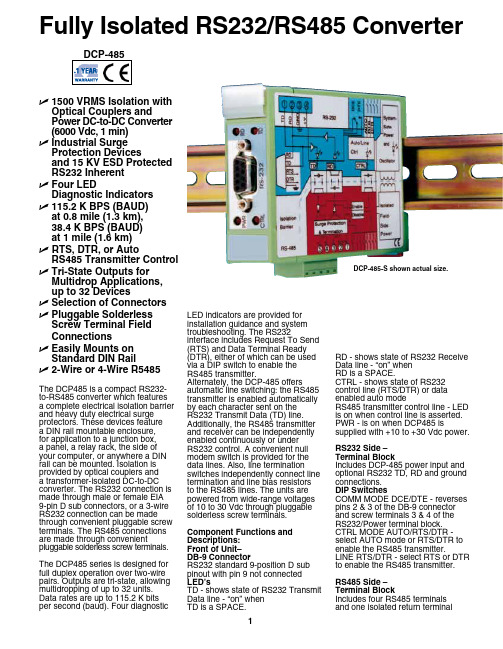
DCP-485The DCP485 is a compact RS232- to-RS485 converter which features a complete electrical isolation barrier and heavy duty electrical surge protectors. These devices featurea DIN rail mountable enclosure,for application to a junction box,a panel, a relay rack, the side of your computer, or anywhere a DIN rail can be mounted. Isolation is provided by optical couplers anda transformer-isolated DC-to-DC converter. The RS232 connection is made through male or female EIA9-pin D sub connectors, or a 3-wire RS232 connection can be made through convenient pluggable screw terminals. The RS485 connections are made through convenient pluggable solderless screw terminals.The DCP485 series is designed for full duplex operation over two-wire pairs. Outputs are tri-state, allowing multidropping of up to 32 units. Data rates are up to 115.2 K bits per second (baud). Four diagnostic LED indicators are provided forinstallation guidance and systemtroubleshooting. The RS232interface includes Request To Send(RTS) and Data Terminal Ready(DTR), either of which can be usedvia a DIP switch to enable theRS485 transmitter.Alternately, the DCP-485 offersautomatic line switching: the RS485transmitter is enabled automaticallyby each character sent on theRS232 Transmit Data (TD) line.Additionally, the RS485 transmitterand receiver can be independentlyenabled continuously or underRS232 control. A convenient nullmodem switch is provided for thedata lines. Also, line terminationswitches independently connect linetermination and line bias resistorsto the RS485 lines. The units arepowered from wide-range voltagesof 10 to 30 Vdc through pluggablesolderless screw terminals.Component Functions andDescriptions:Front of Unit–DB-9 ConnectorRS232 standard 9-position D subpinout with pin 9 not connectedLED’sTD - shows state of RS232 TransmitData line - “on” whenTD is a SPACE.RD - shows state of RS232 ReceiveData line - “on” whenRD is a SPACE.CTRL - shows state of RS232control line (RTS/DTR) or dataenabled auto modeRS485 transmitter control line - LEDis on when control line is asserted.PWR - is on when DCP485 issupplied with +10 to +30 Vdc power.RS232 Side –Terminal BlockIncludes DCP-485 power input andoptional RS232 TD, RD and groundconnections.DIP SwitchesCOMM MODE DCE/DTE - reversespins 2 & 3 of the DB-9 connectorand screw terminals 3 & 4 of theRS232/Power terminal block.CTRL MODE AUTO/RTS/DTR -select AUTO mode or RTS/DTR toenable the RS485 transmitter.LINE RTS/DTR - select RTS or DTRto enable the RS485 transmitter.RS485 Side –Terminal BlockIncludes four RS485 terminalsand one isolated return terminalFully Isolated RS232/RS485 ConverterU 1500 VRMS Isolation withOptical Couplers andPower DC-to-DC Converter(6000 Vdc, 1 min)U Industrial SurgeProtection Devicesand 15 KV ESD ProtectedRS232 InherentU Four LEDDiagnostic IndicatorsU 115.2 K BPS (BAUD)at 0.8 mile (1.3 km),38.4 K BPS (BAUD)at 1 mile (1.6 km)U RTS, DTR, or AutoRS485 Transmitter ControlU Tri-State Outputs forMultidrop Applications,up to 32 DevicesU Selection of ConnectorsU Pluggable SolderlessScrew Terminal FieldConnectionsU Easily Mounts onStandard DIN RailU 2-Wire or 4-Wire R5485DCP-485-S shown actual size.Specifications Baud Rates (bps): 115.2 K, 57.6 K,38.4 K, 19.2 K, 9.6 K, 4.8 K, 0-2.4 K Distance (miles): 0.8, 0.9, 1.0, 2.6,3.5,4.0, 7.0Distance (km): 1.3, 1.5, 1.6, 4.2,5.6,6.4, 11.3Wire Capacitance: equal to 25 pFper foot and up to 32 multidrop units Max Multidrop Units: 32COMMON MODE ISOLATION Surge: 6000 Vdc, 1 minContinuous: 1500 VrmsDifferential Mode Surge Protection: (dc input and RS232inputs and outputs, RS485 inputs and outputs)Modes: Asynchronous 4–wireduplex, 2–wire half duplex, 2–wire simplex Channel Lines: (1) TD, RDControl Lines: (1) RTS, DTRNull Modem Switch:1 (Reverses RS232 pins 2 and 3)RS485 Output Drive: 28 mA max/output RS485 Input Impedance:12 k Ω min/input Power: 10 to 30 Vdc @ 150 mA maxTEMPERATURE Operating Range: 0 to 60°C(32 to 140°F)Storage Range: 0 to 70°C(32 to 158°F)Relative Humidity: 0 to 95%non-condensing Altitude: To 4574 m (15,000')Dimensions:109 H x 84 W x 22.5 mm D (4.3 x 3.3 x 0.89")Weight: 130 g (4.6 oz)MTBF: (2) >100,000 hrsOrdering Example: DCP-485-S and OCW-1 OMEGACARE SM 1-year extended warranty for DCP-485-S adds 1 year to standard 1-year warranty.DCP-485 Block Diagram Dimensions for DCP-485Notes: (1) TD = Transmit Data, RD = Receive Data, RTS = Request to send, DTR = Data Terminal Ready. (2) Ground-benign environmental conditions (no salt atmosphere, <50°C ambient temperature).DIP Switches TD Term - switches a 120 Ωtermination resistor across the RS485 transmit data lines TD A & TD B.RD Pull Up/Term/Pull Dn - RD Term switches a 120 Ωtermination resistor across the RS485 receive data lines. RD Pull Up & RD Pull Dn switch a pull up resistor to RD B’ and a pull down resistor to RD A’, respectively.TD Cont En/Ctrl’d - select continuous enable or RS232 side signal control of the RS485 transmitter. RD Cont En/Ctrl’d - select continuous enable or RS232 side signal control of theRS485 receiver.OMEGACARE SM extended warranty program is available for models shown on this page. Ask your sales representative for full details when placing an order. OMEGACARE SM covers parts, labor and equivalent loaners.。
rs232串口用户手册usermanual
主控机 PC 机
HXSP-2108B 型转换器
485+ 485-
RS-485 通信设备
HXSP-2108B 型转换器
RS-232 通信设备
RS-485 通信设备
五、电源及防浪涌接地保护 1、外 接 电 源 HX SP - 2 1 0 8B 接 口 转 换 器 可 以 采 用 产 品 已 配 的 9V 电 源 适 配 供 电 , 也 可 以 从 其 它 直 流 电 源 或 设 备 供 电 , 供 电 电 压 力 +9V, 电 流为 100Ma。 2、浪 涌 接 地 保 护 : 普 通 的 接 口 转 换 器 没 有 配 备 大能量的保护装置,由于线路感应在接口 数据线上的瞬态高压,试图从设备的最小电 阻路径释放能量到地线。因此容易造成接口 器件的损坏。接口转换器在使用过程中为了 保证通信的安全可靠接地避免悬空。
发送负T- 发送正 T + 接收正 R+ 接收负R- GND
RS-485 定义
485-
485+ N L
N L GND
6 FCN FCN
3.RJ45 脚定义:
RJ45
1
2
3
4
5
6
RS-422
发送正T+ 发送负T- 接收正R+ 接收负R-
GND GND
RS-485 485- 485+
GND GND
4.RJ454 连接图
三、引脚定义:
1.RS-232 端引脚定义:
D B 9Female(PI N) 1 2 3 4 5 6 7 8 RS-232(DCE) D C D TXD R XD D TR G N A D SR R TS C TS
RS232RS485RS422光电隔离转换器使用手册

RS232/RS485/RS422光电隔离转换器使用手册一、概述本转换器是一种多功能RS-232/RS485/RS422接口转换器。
该产品配有外接电源,光隔2KV以上。
具有体积小、传输距离远、速率高、性能稳定等特性。
可广泛应用于工业自动化控制系统、一卡通、门禁系统、停车场系统、自助银行系统、公司员工出勤系统、公路收费站系统等。
是一种性能价格比优良的数据接口转换产品。
内部无需开关设置,可支持32个节点/128个节点型号选择。
二、性能参数1、RS485/422端外接9V/350mA电源。
光电隔离2KV。
RS232开关电源隔离供电。
2、工作方式为同步双工传输。
3、传输介质需采用屏蔽双绞线,线径要求在0.75mm以上.4、传输速率为0-115200bps5、传输距离为1500m(100Kbps时)6、可支持32个节点或128个节点7、工作环境为-20℃到70℃,相对湿度为5%到95%.8、外形尺寸115mmX55mmX23mm三、图形四、连线示意图1、RS485两线连接:图二2、RS-422四线连接:图三五、安装和应用本产品采用DB-9通用输入头并配DB-9至DB-9交叉连接线,方便与电脑RS-232口连接。
输出配连接、拆卸方便的接线柱。
本转换器支持:1、点到点;一点对多点的半双工两线通信模式(485模式) ,见图二2、点到点;一点对多点的全双工四线通信模式(422模式) ,见图三注意:在半双工接线时,为了防止信号的反射干扰,需在线路的终端接一个120欧的匹配电阻。
六、故障及排除RS485不能通信:1、Power LED不亮:检查电源适配器连接及供电是否正常。
2、RS485 LED不亮:A、检查电脑COM口设置是否正确。
B、检查COM口至转换器间转线是否连好。
3、RS485 LED亮但不能通信:检查485输出连线是否正确(485+;485-是否一一对应) 。
检查485输出总线是否短路。
RS422不能通信:1、Power LED不亮,检查电源适配器连接及供电是否正常。
JaRa捷瑞电讯2102G RS232-RS485无源光电隔离转换器产品使用说明书
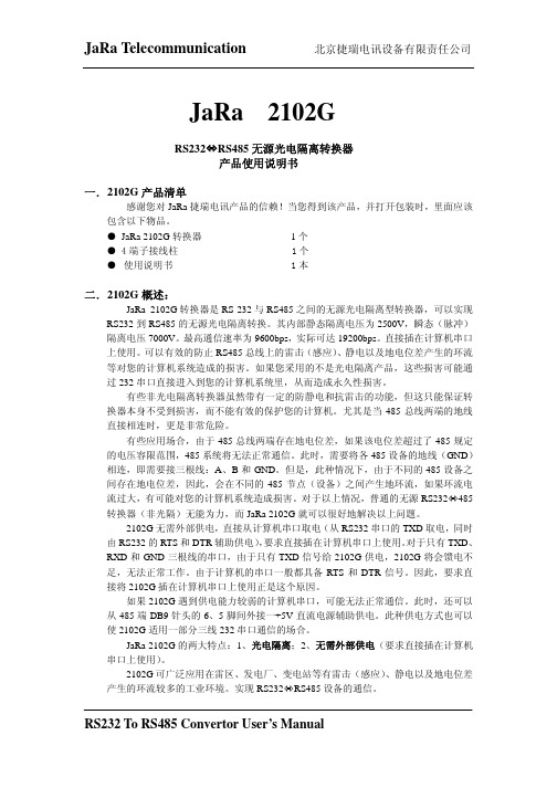
JaRa 2102GRS232ÙRS485无源光电隔离转换器产品使用说明书一. 2102G产品清单感谢您对JaRa捷瑞电讯产品的信赖!当您得到该产品,并打开包装时,里面应该包含以下物品。
● JaRa 2102G转换器1个● 4端子接线柱 1个● 使用说明书 1本二. 2102G概述:JaRa 2102G转换器是RS-232与RS485之间的无源光电隔离型转换器,可以实现RS232到RS485的无源光电隔离转换。
其内部静态隔离电压为2500V,瞬态(脉冲)隔离电压7000V。
最高通信速率为9600bps,实际可达19200bps。
直接插在计算机串口上使用。
可以有效的防止RS485总线上的雷击(感应)、静电以及地电位差产生的环流等对您的计算机系统造成的损害。
如果您采用的不是光电隔离产品,这些损害可能通过232串口直接进入到您的计算机系统里,从而造成永久性损害。
有些非光电隔离转换器虽然带有一定的防静电和抗雷击的功能,但这只能保证转换器本身不受到损害,而不能有效的保护您的计算机。
尤其是当485总线两端的地线直接相连时,更是非常危险。
有些应用场合,由于485总线两端存在地电位差,如果该电位差超过了485规定的电压容限范围,485系统将无法正常通信。
此时,需要将各485设备的地线(GND)相连,即需要接三根线:A、B和GND。
但是,此种情况下,由于不同的485设备之间存在地电位差,因此,会在不同的485节点(设备)之间产生地环流,如果环流电流过大,有可能对您的计算机系统造成损害。
对于以上情况,普通的无源RS232Ù485转换器(非光隔)无能为力,而JaRa 2102G就可以很好地解决以上问题。
2102G无需外部供电,直接从计算机串口取电(从RS232串口的TXD取电,同时由RS232的RTS和DTR辅助供电),要求直接插在计算机串口上使用。
对于只有TXD、RXD和GND三根线的串口,由于只有TXD信号给2102G供电,2102G将会馈电不足,无法正常工作。
RS232、RS485转光纤_光猫使用说明

RS23、RS422、RS485转光纤_光猫使用说明(工业级)一、概述天津三格电子的MS-F155是多功能的支持异步RS-232,RS-485,RS-422通信接口的光纤模块,可以延长RS232、RS422、RS485通信距离,最远可以达到20公里到40公里。
采用光信号传输,模块有很好的抗电磁干扰能力。
防雷设计,可用于比较恶劣的工矿环境。
支持RS-232,RS-485,RS-422多种异步通信协议,可以同时混合使用两个RS-232,4路RS-485或2路RS-422接口,支持2线(半双工)RS-485和4线(全双工)RS-422工作方式。
RS-232信号的传输速率最高为115.2Kbps,RS-485/RS-422的信号传输速率最高可达500Kbps,不同电气标准的接口可以混合使用,可以用RS-232的设备去连接RS-485/RS-422的设备,可以代替RS-232到RS-485/422接口转换器或光电隔离器,并提供了优良的EMI/RFT特性。
RS485接口采用零延迟转换时间技术、自动侦测数据流向的流控技术,使模块使用非常简单。
二、规格与特性电源:宽电源供电,7-24V直流电源。
接口:RS232/RS422/RS485。
可以同时传输2路RS232,4路485或者2路422。
传输速率:RS232可以达到115200bps;RS422 RS485可以达到400Kbps。
通信方式:RS232RS422为全双工/ RS485为半双工。
通信距离:多模可以达到2000米,单模可以达到20-40公里。
光纤:SC、LC可选口,单模,单双纤可选,1310nm、1550nm可选。
保护:15KV静电保护,1600W浪涌保护环境温度:-40---60°C存储温、湿度:-20---50°C 5%---90%体积:长120mm 宽85mm 高25mm四、LED指示灯RS485_1_LED:闪烁表示RS485_1有数据收发;RS485_2_LED:闪烁表示RS485_2有数据收发;RS485_3_LED:闪烁表示RS485_3有数据收发;RS485_4_LED:闪烁表示RS485_4有数据收发;RS232_1_LED:闪烁表示RS232_1有数据收发;RS232_2_LED:闪烁表示RS232_2有数据收发;PWR_LED:灯亮表示电源工作;Fiber_LED:灯亮表示光纤模块工作正常;五、光纤参数单模、SC口(可选择其他接口,LC FC等)、单双纤可选,波长1310nm。
捷瑞 2107系列 RS232 RS485 422转换器使用说明书

JaRa® MODEL 2107系列RS232<->RS485/422转换器使用说明产品概述一 MODEL 2107A接口转换器2107A是RS232到RS422/485的有源双向接口转换器,完全由外部独立电源供电,无需从串口取电。
内部零延时/自动收发智能转换(自动流控)。
可以实现点对点、点对多点,单工、半双工、全双工等传输,可广泛用于RS422/485接口设备的通信网络中。
二 MODEL 2107B接口转换器2107B是RS232到RS422/485的有源光电隔离单向接口转换器,RS422/485端外部独立电源供电,RS232端从串口取电。
内部零延时/自动收发智能转换(自动流控)。
可以实现点对点、点对多点,单工、半双工、全双工等传输,非常适合用于工业控制领域。
三 MODEL 2107C接口转换器2107C是RS232到RS422/485的有源光电隔离双向接口转换器,RS232/RS422/485端全由外部独立电源供电,无需从串口取电,满足任何RS232联入RS422/485网络,内部零延时/自动收发智能转换(自动流控),并同时具有串口光电隔离和电源隔离保护(内部电源隔离模块静态隔离电压达7000V),是专为严格要求的工业控制环境设计开发的,目前业界很好的接口转换器。
MODEL 2107系列产品特性性能参数:串口界面接口兼容EIA/TIA的RS232C、RS485/RS422标准传输介质普通双绞线传输 距离 0-5Km (115200--9600bps) 其中1.2Km(可达到57.6Kpbs)点位数最多32个电源要求需外部供电(其中,2107B的RS232端从串口取电)接头 方式 RS-232:配RJ45转DB9/25孔线缆RS-422/485:DB9针,配六位接线端子信号 RS-232: TxD, RxD, RTS, CTS, DTR, DSR, DCD, GND RS-485:Date+/A,Date-/B, GNDRS-422:TD+,TD-,RD+,RD-,GND工作异步单工,半双工,全双工方式透明通信协议-10℃~70℃工作温度5%~95%相对湿度POWER(红)TD(红)、RD(绿)显示指示备注 无需RTS / CTS硬件流控和软件控制,智能转换使用说明:连接器和信号MODEL 2107系列转换器均采用RJ45转DB9/25线缆与RS232接口相连,RS422/485端采用DB9针头(可加配6位接线柱)与RS422/485总线网络相连。
RS232-RS485无源转换器说明书
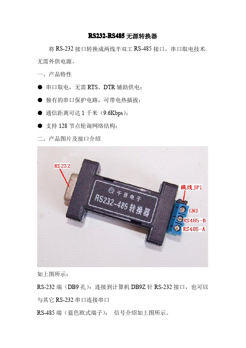
RS232-RS485无源转换器将RS-232接口转换成两线半双工RS-485接口,串口取电技术,无需外供电源。
一、产品特性●串口取电,无需RTS、DTR辅助供电;●独有的串口保护电路,可带电热插拔;●通信距离可达1千米(9.6Kbps);●支持128节点轮询网络结构;二、产品图片及接口介绍如上图所示:RS-232端(DB9孔):连接到计算机DB9Z针RS-232接口,也可以与其它RS-232串口连接串口RS-485端(蓝色欧式端子):信号介绍如上图所示。
跳线J1:120欧终端电阻跳线。
断开(OPEN):终端电阻断开。
短接(CLOSE):终端电阻接入。
匹配电阻,RS-485是差分电平通信,在距离较长或速率较高时,线路存在回波干扰,此时需要在通信线路首末两端并联120Ω匹配电阻。
匹配电阻会降低线路带负载能力,我们推荐在通信速率大于19.2K或线路长度大于200米时,才需加接匹配电阻。
接地说明,RS-485要求通信双方的地电位差小于1V,所以建议一定要将两边的信号地相连,但该信号地不要接大地。
三、应用示例:1、点到点两线半双工通讯2、点到多点两线半双工通讯为防止信号的反射和干扰,长距离传输时需在线路的终端加装匹配电阻。
四、附赠救火车工作室串口调试软件1.2。
使用电脑和485总线连接,进行通讯调试时,可以使用本软件,软件界面如下图:五、技术支持联系方式秦皇岛千目电子有限公司地址:河北省秦皇岛市海港区和平大街和平E站424室技术服务QQ:849046309(救火车)主要技术支持方式邮箱:**************MSN:***************。
RS232 RS485 RS422转以太网串口服务器E810-DTU(1RS1E)使用手册
目录第一章产品概述 (3)1.1 产品简介 (3)1.2 产品规格参数 (3)第二章产品设计介绍 (4)2.1 尺寸图 (4)2.2 标识定义 (4)2.3通信连接示意图 (5)2.3.1 RS232通信连接方法 (5)2.3.2 RS285通信连接方法 (5)2.3.3 RS422通信连接方法 (5)第三章产品功能介绍 (6)3.1 网络基础功能 (6)3.1.1 IP地址介绍 (6)3.1.2 子网掩码介绍 (6)3.1.3 网关介绍 (6)3.1.4 DNS介绍 (6)3.2 串口功能 (7)3.2.1 串口参数介绍 (7)3.2.2 串口成帧机制 (7)3.3 SOCKET功能 (7)3.3.1 TCP Client 功能 (7)3.3.2 TCP Server 功能 (8)3.3.3 UDP Client 功能 (8)3.3.4 UDP Server功能 (9)3.4 特色功能 (9)3.4.1 web 页面配置 (9)3.4.2 心跳包功能 (9)3.4.3 注册包功能 (10)3.4.4 透传云功能 (11)3.4.5 短连接功能 (11)3.4.6 KeepAlive功能 (11)3.4.7 超时重启功能 (12)3.4.8 清除缓存功能 (12)3.4.8 Modbus TCP转RTU功能 (12)3.4.9 Link/数据收发指示功能 (12)3.4.10 恢复出厂设置 (13)第四章快速使用 (14)4.1 上位机介绍 (14)4.2 默认参数 (14)4.3 SOCKET 使用说明 (15)4.3.1TCP Client使用说明 (15)4.3.2TCP Server使用说明 (16)4.3.3UDP Client使用说明 (16)4.3.4UDP Server使用说明 (16)4.4 WEB 介绍 (17)第五章常见问题 (18)5.1 传输距离不理想 (18)5.2 模块易损坏 (18)5.3 误码率太高 (18)第六章修订历史 ......................................................................................................................... 错误!未定义书签。
星辰科技 USB 到 RS232 RS422 RS485 串行适配器产品说明说明书
2 Port USB to RS232 RS422 RS485 Serial Adapter with COM RetentionProduct ID: ICUSB2324852The ICUSB2324852 2 Port USB to RS232 RS422 RS485 Serial Adapter with COM Retention lets you connect every type of serial device to your USB-enabled computer, whether it be for RS232, RS422, or RS485 communication. The adapter features a 9-pin (DB9) male and a 5-pin terminal block serial connector as well as dip-switch controls for easy port configuration with minimal software requirements. The adapter also supports using 2 ports simultaneously, including with mixed protocols; for example RS-232 on port 1, and RS-485 on port 2, or a number of other combinations.For a convenient, and clean installation in office or industrial settings, the RS232/RS422/RS485 USB Adapter is wall-mountable and fully powered via the host USB connection, providing power to the attached serial device without requiring an external power adapter.Backed by a 2-year warranty and free lifetime technical support.Certifications, Reports and Compatibility Applications•Adapting and expanding POS systems•Great for Industrial programmers looking to test new code with serial devices•Connect serial RS232, RS422, or RS485 devices to notebooks ortablet PC’s through the USB port•Perfect for controlling, monitoring, and diagnosing manufacturing machines (CNC, Process Control Equipment, Bar Code Scanners,Serial Printers)•Security device control (key panels, cameras, card readers)Features•Backwards compatible with USB 1.1•USB-powered; No additional external power adapter required •Both ports can function simultaneously with mixed or matchedcommunication protocols•Includes a bracket for wall mounting the USB to Serial adapter •Features rugged screw-lock USB port to ensure cords are not accidentally disconnected•Ability to rename devices for easy recognition•COM Port assignments maintained after reboot•Port 1 (DB9) configurable for RS232, RS422, or RS485; Port 2 (Terminal Block) configurable for RS422 or RS485•Multiple interface modes, including: 4 wire RS422(TxD+/-, RxD+/-), and 2 wire RS485 (DATA+, DATA-)•Supports RS-485 Auto Transceiver Turn Around by Unique Featured ATTA Hardware•External power adapter can be used (not required) if your device needs extra power beyond what the USB host can provide •Transmission Echo for RS485 collision detection•USB to 2 Port Straight-Through RS232/422/485 Serial AdapterWarranty 2 YearsHardware Bus Type USB 2.0Chipset ID FTDI - FT2232HInterface SerialPort Style External HubPorts2Performance Data Bits7, 8FIFO128 BytesFlow Control Xon/Xoff, Hardware, and NoneMax Baud Rate921.6 KbpsParity Odd, Even, Mark, Space, and NoneSerial Protocol RS-232/422/485Stop Bits1, 2Connector(s)Connector Type(s) 1 - USB Type-A (4 pin) USB 2.0 MaleExternal Ports 1 - DB-9 (9 pin, D-Sub) Male1 - Terminal Block (5 Wire)Software OS Compatibility Windows® CE (4.2, 5.0, 6.0), XP Embedded, 98SE, 2000,XP, Vista, 7, 8, 8.1, 10Windows Server® 2003, 2008 R2, 2012, 2012 R2, 2016,2019Mac OS X® 10.6 to 10.15Linux 2.4.x to 4.4.x LTS Versions onlyIndicators LED Indicators 1 - Red - Power LEDPower Center Tip Polarity PositiveOutput Current0.385AOutput Voltage 5 DCPlug Type BPower Source Not Included (not required for standard applications) Environmental Humidity5~95% RHOperating Temperature0°C to 55°C (32°F to 131°F)Storage Temperature-20°C to 85°C (-4°F to 185°F)PhysicalColor GrayCharacteristicsEnclosure Type PlasticProduct Height0.9 in [2.3 cm]Product Length 3.2 in [82.3 mm]Product Width 1.7 in [44.2 mm]Weight of Product10.6 oz [300 g]PackagingPackage Height 1.6 in [40 mm]InformationPackage Length8.2 in [20.8 cm]Package Width 5.7 in [14.4 cm]Shipping (Package) Weight10.9 oz [310 g]What's in the Box Included in Package 1 - Wall mounting bracket1 - USB to RS232/RS422/485 Adapter1 - USB A to B Cable1 - Driver CD1 - Installation GuideProduct appearance and specifications are subject to change without notice.。
- 1、下载文档前请自行甄别文档内容的完整性,平台不提供额外的编辑、内容补充、找答案等附加服务。
- 2、"仅部分预览"的文档,不可在线预览部分如存在完整性等问题,可反馈申请退款(可完整预览的文档不适用该条件!)。
- 3、如文档侵犯您的权益,请联系客服反馈,我们会尽快为您处理(人工客服工作时间:9:00-18:30)。
R S232/RS485转换器使用说明书
一、 产品简介
HEXIN-III 型转换器之间的双向接口的转换器,应用于主控机之间,主控机与单片机或外设之间构成点到点,点到多点远程多机通信网络,实现多机应答通信通信,广泛地应用于工业自动化控制系统,一卡通、门禁系统、停车系统、自助银行系统、公共汽车收费系统、饭堂售饭系统、公司员工出勤管理系统、公路收费站系统等等。
HEXIN-III 型转器,能够将RS-232串行口的TXD 和RXD 信号转换成两衡半双工的RS-485信号。
无需外接电源,可直接从RS-232端口的3脚窃电,同时由7脚请求发送(RTS ),4脚数据终端准备好(DTR )给HEXIN-III 辅助供电,自动的流控使你不必重新设置,硬件与安装软件使用非常简单。
二、 性能参数
1、 串口特性:接口兼容EIA/TIA 的RS-232C ,RS-485标准。
2、 电气接口:RS-232端DB9孔型边接口,RS-485端DB9针型连接器、配接线柱(五位接线)。
3、 工作方式:异步半双工。
4、 传输介质:普通线、双绞线或屏蔽线。
5、 传输速率:300~115-21BDS 。
6、 传输距离:5米(RS-232端)1.200米(RS-485端)。
7、 通信协议:透明。
8、 工作环境:-10℃到85℃相对湿度为5%到95%。
9、 信号:RS-232:TXD 、RXD 、RTS 、CTS 、DTR 、DSR 、DCD 、CND ;
RS-485:Date+、Date-。
GND 三、接线和信号:
RS232端(DB9母头) RS485(DB9M 公头)
HEIN-III 转换器采用DB9型的母头连接口与RS232接口相连,另一端DB9的公头连接器与
RS485接口相连。
RS232引脚定义
RS485引用脚定义
其工作电源有两种情况:直接从RS232端口向3脚供电,同时,由7(RTS )、4(DTR )脚给HEXIIN-III 型辅助供电,当RS232不能正常供电时,可由RS485端的DB9M6(+12V )和5脚(GND )供电。
四、 安装及应用
1、 安装:①在安装HEXIN-III 型产品之前,准备两根(可双绞线);
②关闭设备串行口(关机); ③HEXIN-III 型转换器的RS232端口是DCE 方式, 可以直接插入DTE 设备的DB9M 串行口(如计算机 的COM 口),并从其中的TXD 、DTR 、RTS 信号窃 电,并注意信号电平应大于+5V ,如果设备是DCE 方 式,必须如下连接线:
2、应用:
1、RS232设备与RS485设备通讯该方式主要应于在控 制端设备是RS232接口,被控制端设备是RS485接口, 两端设备因电气特性不一,不能直接相通,采用
HEXIN-III 型转换器即可透明的将RS232接口信号转换 为RS485信号。
R S 232 通讯设备
HEXIN-II I 型转换器 R S 485 通讯设备 485+
485-2、RS485组网应用
一台RS232主机欲控制多达32个RS485从设备时, 可以使用该方式,为了防止信号的反射和干扰,需 在线路的终端接匹配电阻(120欧、1/4瓦)。
主控机 PC 机
HEXIN-III 型转换器
RS485 通讯设备
485-
485+
HEXIN-III
型转换器
RS485 通讯设备
RS485 通讯设备
RS485设备与HEXIN-III
型的连接如下:
主要有以下两种连接方式: ① 两个HEXIN-III 型连接
HEXIN-III ……………………………HEXIN-III Dat e (+)…………………………………Dat e (+) Date (-)…………………………………Date (-) GND …………………………………………GND
② HEXIN-III 型转器和RS-485设备相连 HEXIN-III ……………………………RS485设备
Dat e (+)…………………………………T+/R+or485+
Date (-)…………………………………T-/Ror-485- GND …………………………………………GND 五、故障分析: 1、 数据通信不成功;
a 、 检测RS232接口是否正确;
b 、 检测RS485按口是否正确;
c 、 检测RS232信号电平(TXD 、DTR 、
RTS 是否低于+5V ,若低于+5V 可在 DB9M 的第6脚供电。
2、 数据丢失或乱码
a 、 检测数据通信设备两端数据速率,格式是
否一致;
b 、 可以加匹配电阻1/4W 120W 。
