SP3D操作
sp3d教程Drawings
The priority is from the Top down, so if an object finds its match in several different filters, the last one (bottom most) wins.
© 2004. Intergraph Corporation. All Rights Reserved.
© 2004. Intergraph Corporation. All Rights Reserved.
Drawing Volumes by selection
© 2004. Intergraph Corporation. All Rights Reserved.
Multiple views for one volume
Designer Workflow (in Drawings task)
– – – – Create drawings for the drawing type for which volumes are placed Set drawing level properties if needed Update drawing Manually add additional Labels and Dimension if needed
© 2004. Intergraph Corporation. All Rights Reserved.
Snapshot Drawings
Used where drawing layout is different for each drawing (e.g. one drawing containing views showing different parts of 3D) Each drawing is independent regarding view arrangement and view properties Each view is individually saved (snapshot) and composed on a drawing Preserves workspace definition at the time of snapshot – both workspace and range considered View style acts as “override” – everything in workspace ends up on drawing in default symbology, everything mentioned in view style follows symbology therein
sp3d基础操作中文教程
精选课件
22
位置关联
• 面配合关联
- 在两个平面之间定义 - 面矢量指向对方
精选课件
23
位置关联
• 排成一行
- 在两个平面之间定义 - 两个表面的法线指向同一个方向
精选课件
24
位置关联
• Mate/Align 关联
- 当选择圆柱对象时, 系统使用柱轴产生关联 - 两个柱轴成一条直线
精选课件
25
原点
精选课件
Datum Shape
35
外形体
• 可以定义多边体外型
多边体
精选课件
36
从外部文件插入设备外形体
• 这个命令可以将格式为 SAT 的外部设备文件插入进来 • 插入进来的几何体的原点由SAT文件的坐标系统决定
精选课件
37
Pipeline(管线)
在 System and Spec 环境建立 ,它是 Pipe Runs 的上一级管理层
Axis
Before
Axis
精选课件
After
28
旋转设备
• 可以使用专门的旋转设备命令
Rotation Axis
• 也可以使用通用旋转命令
精选课件
29
Rotate Equipment
• 指定或修改旋转轴 • 假如定义了约束条件, 则只显示一种选择 (与约束面垂直)
Rotation Axis
精选课件
每一个规则都可以设定是否需 要显示这些特定的图形属性
精选课件
15
Control Point(控制点)
定义
– 在模型中用一个点代表一个三维对象
– 用于在两维图纸上的标号定位 – 用于生成 Cable Marker – 放置方法:
关于PMDS和SP3D中间格式应用和转换说明

PDMS模型中间格式说明一、PDMS模型导出方法⏹RVM格式文件导出Utilities-Export-Create⏹RVM格式导出设置1、设置文件访问路径,注意文件格式(如:D:\MOD.RVM)2、选择设置RVM格式模型的文本制式3、添加导出模型4、添加制定配色文件5、确认导出二、导出att属性文件⏹ATT格式文件导出Utilities-Export-Dump Attributes⏹att格式导出设置1、选择需要导出的模型2、设置导出存放路径(如:D:\MOD.ATT)3、确认导出三、PDMS模型文件说明和注意⏹PDMS模型根据需求可以设置导出细致成度(值越低效果越好,响应导出模型数据就越大)⏹在导出模型前应检查项目内设单位(常用毫米MM)⏹RVM和ATT格式应用用于EDIS模型交互、也用于目前可视化模型优化处理参考模版SP3D模型中间格式说明一、SP3D模型导出方法(方法有几种,以下举例常用的方法)⏹模型文件导出窗口Tools-Drawing Console⏹在出现的对话窗口右击新建文件,并在该文件下创建3D Modle Data⏹右击3D Modle Data设置Setup1、设置导出模型Filter2、设置导出模型格式(目前支持VUE +XML和sat两种文件)3、选择存放路径(注:VUE文件需要两个都需要设置,SAT 只需设置前一个)4、确认导出二、SP3D模型格式说明⏹VUE+XML模型目前只能用SP3D配套的review阅览软件打开(也可以用于SPF发布,但需要配套的发布软件)⏹SAT模型可以用第三方软件打开如Naviswork 3DMAX等,目前用于三维可视化模型优化参考模型(由于属性和模型数据大小问题,建议将模型拆分命名导出,管线以管线号为单位、机械以设备位号为单位、其他可按照区域专业导出)。
SP3D管道支吊架库开发及应用

44CHEMICAL ENGINEERING DESIGN化工设计2018,28(4) SP3D管道支吊架库开发及应用刘宝洪#中海油石化工程有限公司济南250101摘要通过与传统管道支吊架设计对比,突出了SP3D软件管道支吊架库的自动化和智能化。
本文介绍软件的系统架构方案和数据,通过范例介绍了支吊架的发过程。
关键词SP3D管道支吊架软件开发石油化工行业的 发展和计算机 丨技术的不断完善,工程 已经由二 渐变为。
Sm artPlant3D*1,2](简SP3D)是鹰图公司开发的三维设计软件,是众多 工程公司重 发的新一代 成 的重要组成部分。
该软件有专门的管 的块,可以实 的!和纸的自动生成 能。
但是,SP3D面简单,这就意味软件后 要 的设置。
软件 只了,忽略了软件的定制和开发,很 f 能化的模块并没有发 有功能*!]。
管 吊架模块就是很好的例子,SP3D默认自带的管道支 库主要是以国外公司的产品为依据开发,标范、物理外形和 格都与国内不一致,不合国内工程公司实 ,不能 。
因此,公司开展了 二 发,开发了满足公司项目需求的SP3D实体支吊架库。
1系统架构方案SP3D数据库*3]结构主要有四部分组成:用于 连接项目的连接数据库集(Site D atabase S e t)、用的据库集(C atalogD atabase S e t)、放目的项目数据库(M odel D atab a s e)和用 于输出 图表的报告数据库集 (Report D atabase S e t)。
S P3D以数据为中心,软件用到的 属性和 *4,5]都 E x c e l的形在于后台,过V B程序驱动调取。
本工程为鹰图SP3D进行开发,整体的技术架构以鹰图SP3D为,据目本身的,搭建 的据 和业 。
系统整 层架构组成,统最上层为S u p p o rt模块,中层的部分为数据和A P I模块,最下层的则为基础的 SP3D模块。
五氯化磷中磷原子的杂化方式

五氯化磷中磷原子的杂化方式五氯化磷是一种无机化合物,也是一种重要的有机合成试剂。
在有机合成领域中,五氯化磷常用于酰化、羰基化、醚化、脱水等反应中。
其中,五氯化磷中的磷原子起着至关重要的作用。
本文将详细介绍五氯化磷中磷原子的杂化方式。
一、五氯化磷的基本结构五氯化磷的分子式为PCl5,它由一个磷原子和五个氯原子组成。
在分子结构上,五个氯原子呈正四面体排列,而磷原子处于正四面体的中心位置。
二、杂化概念及分类杂化是指一个原子内部不同轨道之间混合形成新的轨道的过程。
在分子结构中,杂化可以帮助我们更好地理解分子几何形态。
常见的杂化类型有sp、sp2、sp3等。
三、PCl5中磷原子的杂化方式根据VSEPR理论(分子几何理论),PCl5分子属于三角双锥型结构。
在此结构下,每个氯原子占据了正四面体底部的三个位置,而磷原子则处于正四面体的中心位置,并向上延伸一个轴。
在PCl5分子中,磷原子的杂化方式为sp3d杂化。
四、sp3d杂化sp3d杂化是指一个原子内部,s轨道、p轨道和d轨道混合形成新的五个等能量的杂化轨道。
在PCl5分子中,磷原子由于需要与五个氯原子形成共价键,因此需要形成五个等能量的杂化轨道。
五、PCl5分子的空间构型由于磷原子通过sp3d杂化形成了五个等能量的杂化轨道,因此它可以与五个氯原子形成共价键。
在PCl5分子中,每个氯原子都与磷原子通过单键相连。
在空间构型上,PCl5分子呈三角双锥型结构。
六、总结本文介绍了五氯化磷中磷原子的杂化方式及其空间构型。
在实际应用中,对于有机合成反应来说,理解五氯化磷中磷原子的性质和特点对于反应结果具有重要意义。
因此,在学习有机合成反应时,我们也需要深入了解五氯化磷分子结构的相关知识。
Tekla Structures与SmartPlant D连接流程
Tekla Structures与SmartPlant3D连接流程文件12月20日, 2007 Michael Gustafson, Tekla Inc.目的这个文档的目的是定义整合Tekla Structures(TS)和SmartPlant(SP3D)的范围和步骤流程。
内容基础并且包括了可以应用到工业领域多个学科比如能源和核工业的许多好的实践经验。
要注意的是,这个文档仅是一个指导文件,我们推荐用户根据自己的需要进行一些自行的设置。
流程范围第一阶段的工作通常基于将结构节点从Tekla Structures转换到SP3D。
这一流程的范围是延伸扩展TS和SP3D的持续整合。
数据转换的方法第一阶段的数据主要转换方法是CIS/2(CIMSteel2),这种格式是钢结构领域非常普通的格式,并且它的应用已经延伸到了混凝土结构的线性构件(开口的混凝土板、墙板)。
未来阶段TS和SP3D之间的发展很可能延伸到以例如CIS2作为数据转换办法的STEP。
第二种数据转换的格式是DGN(或DWG),DGN可以用来导入所有不包括在CIS/2的格式的对象参考模型。
阶段I –从Tekla输出数据并且输入到SmartPlant (V7-SP2) 用户有几个可行的流程来合作。
其中的2个流程如下方所示,描述的是他们和民用的或使用Tekla Structures的结构工程师或使用SP3D的机械/电力/管道工程师相互之间的关系。
流程 1 下面的示意图1就是流程1的概念图。
示意图 1 –任务向导流程1虽然在结构数据转换中有几个几个切入点,流程1还是集中将Tekla Structures的内容导入到SmartPlant产品中,这种数据转换通常是一个单向的流程;然而3-D协调和决策的参考对象从SmartPlant交换到Tekla是由结构团队来完成的。
这个流程的简单翻译就是包括在Tekla Structures(TS)中开始创建钢结构和混凝土对象。
析SP3D软件的ISO出图模板定制
析SP3D软件的ISO出图模板定制刘豫【摘要】The current 3D digital modeling is widely applied in all kinds of engineering design, greatly improved the ef-ficiency of the design work, but it needs to convert three-dimensional model plane drawings for construction, so as to al-low a smooth docking design unit and construction unit and construction accurately. This article mainly aims at Smart-Plant3D 3D design software, through the brief introduction to ISO drawing frame work customization with living example, it can enhance design efficiency and improve the quality of engineering design.%当前三维数字化建模广泛应用于各类工程设计中,大幅度提高了设计工作的效率,但是三维的模型需要转换为平面图纸供施工使用,这样才能使得设计单位和施工单位顺利对接并准确施工。
本文主要针对SmartPlant3D三维设计软件,通过工作实例简介ISO图框的定制,可以提升设计效率并且提高工程设计质量。
【期刊名称】《办公自动化(办公设备与耗材)》【年(卷),期】2016(000)011【总页数】2页(P38-39)【关键词】SP3D软件;ISO图框;定制【作者】刘豫【作者单位】青岛海工英派尔工程有限公司青岛 266101【正文语种】中文【中图分类】TU85;S611管道ISO图(管道轴测图)中包含了管道的走向,管道管件的材质、数量,建北标等信息,是现场管道施工的重要图纸。
SP3D管道等级库制作操作手册
SP3D RDB 操作手册1.前期准备参考资料:PipingReferenceData.pdf1.1.选择制作等级的样板文件复制…\SmartPlant\3D\Workstation\CatalogData\BulkLoad\DataFiles中的AllCodeLists.xls、Piping Catalog.xls、Piping Specification.xls到新建文件夹,取消只读并改名,在这里我新建了一个SP3D RDB文件夹,并将上面三个文件改名为CodeLists_sample.xls、Piping Catalog_sample.xls、Piping Specification_sample.xls。
1.2.文档的用途CodeLists_sample.xls:定义等级制作中所需用到的codePiping Specification_sample.xls:定义管道等级规定的信息Piping Catalog_sample.xls:定义管道部件的尺寸信息1.3.制作等级需要的文件、文档管道材料等级表材料等级表中所涉及到的标准此处选择以制作成达项目中的B1C等级为例子2.CodeLists_sample.xls的制作CodeLists_sample.xls相当于PDS的Standard Note Library Manager中的各个Code表。
整理B1C等级中的尺寸标准号、管表号、流体代码、绝热材料、管道材料、压力、端面形式等,比对原先CodeLists_sample.xls中的GeometricIndustryStandard、ScheduleThickness、FluidCode、InsulationMaterial、MaterialsGrade、PressureRating、EndPreparation等工作表,如这些工作表中缺少相应的信息的话进行添加并编码。
以管表号为例,B1C中的管表号为CD-nn(nn代表数字及STD、XS、XXS),原先的ScheduleThickness中并没有,所以需要添加,我们添加在Company Standards层次下,编号从10001开始(编号不可重复),并在HEAD列添加A,结果如下:在CodeLists_sample.xls中标有颜色的sheets需要添加编码的可能性比较大在后期制作Piping Catalog.xls、Piping Specification.xls的时候还可能会遇到漏填的code,多人做表的时候记得code一定要统一。
SmartPlant3D_SP3D软件 基础操作
SmartMarine 3DCommon Applications LabsVersion 7.3October 2007CopyrightCopyright © 2007 Intergraph Corporation. All Rights Reserved.Including software, file formats, and audiovisual displays; may be used pursuant to applicable software license agreement; contains confidential and proprietary information of Intergraph and/or third parties which is protected by copyright law, trade secret law, and international treaty, and may not be provided or otherwise made available without proper authorization.Restricted Rights LegendUse, duplication, or disclosure by the Government is subject to restrictions as set forth in subparagraph (c) of the Contractor Rights in Technical Data clause at DFARS 252.227-7013, subparagraph (b) of the Rights in Computer Software or Computer Software Documentation clause at DFARS 252.227-7014, subparagraphs (b)(1) and (2) of the License clause at DFARS 252.227-7015, or subparagraphs (c) (1) and (2) of Commercial Computer Software--Restricted Rights at 48 CFR 52.227-19, as applicable.Unpublished---rights reserved under the copyright laws of the United States.Intergraph Corporation Huntsville, Alabama 35894-0001Warranties and LiabilitiesAll warranties given by Intergraph Corporation about equipment or software are set forth in your purchase contract, and nothing stated in, or implied by, this document or its contents shall be considered or deemed a modification or amendment of such warranties. Intergraph believes the information in this publication is accurate as of its publication date.The information and the software discussed in this document are subject to change without notice and are subject to applicable technical product descriptions. Intergraph Corporation is not responsible for any error that may appear in this document.The software discussed in this document is furnished under a license and may be used or copied only in accordance with the terms of this license.No responsibility is assumed by Intergraph for the use or reliability of software on equipment that is not supplied by Intergraph or its affiliated companies. THE USER OF THE SOFTWARE IS EXPECTED TO MAKE THE FINAL EVALUATION AS TO THE USEFULNESS OF THE SOFTWARE IN HIS OWN ENVIRONMENT.TrademarksIntergraph, the Intergraph logo, SmartSketch, FrameWorks, SmartPlant, INtools, MARIAN, and PDS are registered trademarks of Intergraph Corporation. Microsoft and Windows are registered trademarks of Microsoft Corporation. MicroStation is a registered trademark of Bentley Systems, Inc. ISOGEN is a registered trademark of Alias Limited. Other brands and product names are trademarks of their respective owners.Table of ContentsTable of ContentsLAB-1: Session File, Tasks, View and Window Management.................................... 4 LAB-2A: Filter Management – System ....................................................................... 8 LAB-2B: Filter Management – Object type............................................................... 15 LAB-2C: Filter Management – Volume Filter........................................................... 17 LAB-2D: Filter Management – Properties (Optional Lab) ........................................ 20 LAB-2E: Filter Management – Properties (Optional Lab) ........................................ 26 LAB-2F: Filter Management – Properties (Optional Lab)......................................... 31 LAB-2G: Filter Management – Properties (Optional Lab) ........................................ 34 LAB-3: Creating Surface Style Rule.......................................................................... 37 LAB-4: Work Break Down Structure ........................................................................ 40 LAB-5: Inserting Control Points ................................................................................ 42 LAB-6: Tool Tip Editing ( Optional lab)................................................................... 44 LAB-7: SQL Filter (This lab is for Advance users only)........................................... 47SmartMarine 3D Common Applications Labs 3Common ApplicationsLAB-1: Session File, Tasks, View and Window ManagementObjectiveAfter This Lab Students will be able to Create a session file, modify settings, setup views and move around in a model Lecture: Instructor Needs to explain session template, session file, tasks, options, views and view manipulations 1 Start SmartMarine 3D using Start – Programs – Intergraph SmartMarine 3D –SmartMarine 3D. 2 From the New dialog box, select the Empty template and click OK3 From the Tasks menu, select Configure Task List4 SmartMarine 3D Common Applications LabsCommon Applications4 Select all tasks from the left side and click Add. Then click OK. 5 Now select Common from the Tasks menu. 6 From the Window menu, select New Window three times such that four windowsare open. 7 From the Window menu select Tile Horizontally. 8 Activate GraphicView1 by clicking in its title bar. 9 From the named views pulldown on the Common toolbar, select Front.10 Similarly set GraphicView2 to Top, GraphicView3 to Right and GraphicView4 to Isometric.11 Select Tools , Options to bring up the Options dialog box. 12 On the units of measure tab, select ft-in for distance.SmartMarine 3D Common Applications Labs 5Common Applications13 On the SmartSketch tab, set the dwell time for stack = 0.1 Seconds 14 Select file, Save as and save the session file on your desktop For SmartMarine 3D Setup and Admin class: This session file can be saved as session template. To save this as template, Select File menu, Save As and save this session template in \ProductDir\CommonApp\SessionTemplates\General The location for the Session Templates can be changed using the Tools->Option dialog box. Open this dialog and select the File Locations Tab. You can change this location to a UNC path and store all your session templates there.6 SmartMarine 3D Common Applications Labs15 Select File menu –> Define WorkspaceCommon Applications16 Select the available training Ship 17 Under filters, select more to open the Select Filter dialog 18 Expand the Ship Filters folder, Select all filter and Ok on the form19 Ok on the define Workspace Form and Fit all views 20 Practice Different View Manipulation CommandsSmartMarine 3D Common Applications Labs 7Common ApplicationsLAB-2A: Filter Management – SystemObjectiveAfter This Lab Students will be able to Create and or display different type of filters Lecture: Instructor Needs to explain filter creation, display, modify and selection. 1 Select File, Define Workspace2 Select More… to open the Select Filter dialog 3 Expand the Ship Filters folder, Select all filter and Ok on the form 4 Ok on the define Workspace Form and Fit all views 5 Select File, Define Workspace or CTRL W, select more… 6 Select My Filters folder, Select the Simple Filter Icon to open The New FilterProperties dialog box.8 SmartMarine 3D Common Applications LabsCommon Applications 7 Name the filter “Unit 1” 8 Select Area2 , Unit 1 on the System Tree to select objects 9 Expand Coordinate Systems by clicking on the + sign.Note: Do NOT click the name ‘Coordinate System’ 10 Press and hold the Ctrl key on the keyboard and select Unit 1 CS. 11 Click OK to accept the filter definition.12 Select the filter “Unit 1” 13 Click OK to accept the selected filter 14 Click OK to bring all Unit1 objects into the workspace.SmartMarine 3D Common Applications Labs 9Common Applications 15 Your View should now resemble the following graphic.16 Select Define Workspace or CTRL W, select more… 17 Select My Filters folder, Select the Simple Filter Icon to open The New FilterProperties dialog box. 18 Name the filter “Unit 2”. Select Unit 2 on the System Tree to select objects 19 Expand Coordinate Systems by clicking on the + sign.Note: Do NOT click the name ‘Coordinate System’ 20 Press and hold the Ctrl key on the keyboard and select Unit 2 CS. Click OK toaccept the filter definition. 21 Select the filter “Unit 2”. Click OK to accept the selected filter. 22 Select OK to bring all Unit 2 objects into the workspace10 SmartMarine 3D Common Applications LabsCommon Applications23 Create a new Simple Filter named Building 1, to include Building 1 and Building 1 CS.SmartMarine 3D Common Applications Labs 11Common Applications 24 Create a new Simple Filter named Amines Unit, to include Amines Unit andAmines Unit CS 25 Create a new Simple Filter named Unit 1 & Unit 2, to include Unit 1, Unit 2, Unit1CS and Unit 2 CS12 SmartMarine 3D Common Applications Labs26 Your view should resemble thisCommon Applications27 Create a new Simple filter Building 1 & Unit 2, to include Building 1, Unit 2, Building 1 CS and Unit 2 CS28 Select Define Workspace and select Unit 1 to Display all objects in Unit 1 SmartMarine 3D Common Applications Labs 13Common Applications 14 SmartMarine 3D Common Applications LabsCommon ApplicationsLAB-2B: Filter Management – Object type(Delivered Filters – Selection only)After This Lab Students will be able to select objects using object type filters Lecture: Instructor Needs to explain selection of objects using different filters. Also explain/show delivered catalog filters 1 Display Unit 1 if not already displayed 2 Select Tools, Select by Filter command to open the Select Filter dialog box. 3 Under Catalog filters, expand Default Filters, SMARTMARINE 3D ObjectFilters, Object Types and select Structure(select structure filter not the folder) 4 Click OK to select all Structural objects in Displayed filter 5 Your View should now resemble the following graphic.6 Select Tools, Hide7 Your view should resemble this SmartMarine 3D Common Applications Labs 15Common Applications8 Select tools, show all 9 Select Tools, Select by Filter command to open the Select Filter dialog box. 10 Under Catalog filters, expand Default Filters, SmartMarine 3D Object Filters,Object Types and select Cableway(select Cableway filter not the folder) 11 Click OK to select all Cableway objects in Displayed filter 12 Select Format Styles, Under Surface Tab select Green Color and select ApplyButton 13 System will change all Electrical Objects to Green Color.Note: To change the Cableway back to original color, select cableway objects using same filter, select format - Styles and Select Apply Style by Rule and apply16 SmartMarine 3D Common Applications LabsCommon ApplicationsLAB-2C: Filter Management – Volume FilterObjectiveAfter This Lab Students will be able to Create and/or display filters based on Volumes Lecture: Instructor Needs to explain Volume filter creation, display, modify and selection.1 Select define WorkSpace and select more 2 Select the My Filters folder 3 Select the Simple Filter Icon to open The New Filter Properties dialog box 4 Name the filter “Volume Unit 1” 5 Select Ship name on Systems Tab 6 Open Names Space Tab. Open the Layout volume by Clicking on + sign 7 Select Volume Unit 1 8 Open the Volume Tab, and select Volume Unit 1SmartMarine 3D Common Applications Labs 179 Click OK 10 Select Volume Unit 1 and OK 11 Ok on the define Workspace Form 12 Your view should resemble thisCommon Applications13 System display Volume Unit 1, and all objects which are fully or partially inside the volume14 To display objects only within the volume, select the volume and use clip by objects. Select the Volume(box) and do tools hide.18 SmartMarine 3D Common Applications LabsCommon Applications 15 Select Tools->Show All to displays all objects again. Go to View->Clear Clippingto remove the clipped volume. 16 Create a new Filter name Volume Unit 2, to include Shipname from Systems tab,Volume unit 2 from Named space tab and Volume Unit 2 from Volume tab 17 Display Volume Unit 2. Now select the volume unit 2 from space tab onworkspace explorer, and clip by object. Hide the Volume box.18. Select Tools->Show All to displays all objects again. Go to View->Clear Clipping to remove the clipped volumeSmartMarine 3D Common Applications Labs 19Common ApplicationsLAB-2D: Filter Management – Properties (Optional Lab)Defining a Filter based on Properties – Equipment Approval Status (Asking Filter)1 Define Workspace to show Unit 1 2 Go to Tools, Select by Filter command to open the Select Filter dialog box 3 Select the My Filters folder. Select the Simple Filter Icon to open The New FilterProperties dialog box. 4 Name the filter “Equipment by Approval Status” 5 Switch to the Properties tab and click in the Property field. 6 From the pulldown control, select More…7 This brings up the Select Properties dialog. In the Object type used as basis for property identification, select More…20 SmartMarine 3D Common Applications LabsCommon Applications 8 Expand the Tree, and select Equipment under Equipment and Furnishing9 Ok on the form 10 Under Relationships, Select Direct Property of the Object 11 Under Display Property in this Category, Select StandardSmartMarine 3D Common Applications Labs 21Common Applications12 Select Approval Status under properties and Ok on the form 13 Check the box under Ask22 SmartMarine 3D Common Applications Labs14 Switch to Object Type Tab 15 Expand Equipment and Furnishing 16 Select Equipment as Object TypeCommon Applications17 OK on the form 18 Select the Equipment by Approval Status filter and OK on the select filter form 19 Select Approved for the ValueSmartMarine 3D Common Applications Labs 23Common Applications20 Ok on the form. System will highlight all Approved Equipment in your Workspace24 SmartMarine 3D Common Applications LabsCommon Applications 21 Select Tools, Select by Filter and Select Equipment by Approval Status filter. 22 Select In Review for Value and Ok on the form. System will highlight allEquipment with Status of in review.23 Similarly select all Equipment with Approval status of working.SmartMarine 3D Common Applications Labs 25Common ApplicationsLAB-2E: Filter Management – Properties (Optional Lab)Defining a Filter based on Properties – Piping Run NPD1 Define Workspace to show Unit 1 2 Switch Task to Piping 3 Select Tools, Select by Filter command to open the Select Filter dialog box. 4 Select the My Filters folder. Select the Simple Filter Icon to open The New FilterProperties dialog box. 5 Name the filter “Piping Run by NPD” 6 Switch to the Properties tab and click in the Property field 7 From the pulldown control, select More… 8 Expand the Select Object Type tree and Select Pipe Parts and click OK.26 SmartMarine 3D Common Applications LabsCommon Applications 9 In the Relationship pulldown control, select Run to Part-Owner10 In the Related object Type, select More… to bring up the Select Object Type dialog box. Expand the Select Object Type tree and Select Pipe Run and click OK.SmartMarine 3D Common Applications Labs 2711 In the property grid select NPD option and click OK.Common Applications12 Select equal operator in the operator field 13 Key-in 10 in the value field. 14 Repeat the above steps to include the NPD Unit type in the property grid. 15 Select contains operator in the operator field28 SmartMarine 3D Common Applications Labs16 Key-in “in” in the value fieldCommon Applications17 Click OK to create the filter. OK to accept it. 18 Your View should now resemble the following graphic.SmartMarine 3D Common Applications Labs 29Common Applications 30 SmartMarine 3D Common Applications LabsCommon ApplicationsLAB-2F: Filter Management – Properties (Optional Lab)Defining a Filter based on Properties – Structural Section Names1 Define Workspace to show Unit 1 2 Select Tools -> Select by Filter command to open the Select Filter dialog box 3 Select the My Filters folder. Select the Simple Filter Icon to open The New FilterProperties dialog box. 4 Name the filter “Members by Section Name” 5 Switch to the Properties tab and click in the Property field 6 From the pulldown control, select More… 7 Select Member part prismatic, under Structure – Members 8 Under Relationship, Select Member part to Cross Section 9 Under Related object type, Expand the Select Object Type tree and select CrossSection under Catalog 10 Under Display Property in this Category, Select Standard 11 Scroll down and select Section nameSmartMarine 3D Common Applications Labs 31Common Applications12 Ok on the form 13 Select = for operator. 14 Type C10X15.3 for section name and ok on the form 15 Select Members by Section Name filter and select ok 32 SmartMarine 3D Common Applications LabsCommon Applications 16 System Highlights all C10X15.3 in the WorkspaceSmartMarine 3D Common Applications Labs 33Common ApplicationsLAB-2G: Filter Management – Properties (Optional Lab)Defining a Filter based on Properties – Cableway Vendor Name1 Define Workspace to show Unit 1 2 Select Tools, Select by Filter command to open the Select Filter dialog box 3 Select the My Filters folder. Select the Simple Filter Icon to open The New FilterProperties dialog box. 4 Name the filter “Tray by Vendor” 5 Switch to the Properties tab and click in the Property field 6 From the pulldown control, select More… 7 Select Cableways parts, under Cableway 8 Under Relationship, Select Part to Catalog Definition 9 Under Related object type, Expand Catalog, Catalog Parts and select CableTrayPart 10 Under Display Property in this Category, Select Standard 11 Scroll down and select Manufacturer34 SmartMarine 3D Common Applications LabsCommon Applications12 Ok on the form. Select = for operator 13 Select Cooper B-Line for vendor from the Code list and ok on the form 14 Select Tray by Vendor filter and select okSmartMarine 3D Common Applications Labs 3515 System Highlights all Cooper B-Line TraysCommon Applications36 SmartMarine 3D Common Applications LabsCommon ApplicationsLAB-3: Creating Surface Style RuleObjectiveAfter This Lab Students will be able to Create surface style rules. Surface style rules combine filters with surface styles and apply them to selected aspects of objects. Lecture: Instructor Needs to explain creation of surface style rules. 1 Set your workspace to show Unit 1 2 Select Format , Surface Style Rules 3 Click New to define a new surface style rule.4 Key in ‘All Piping ’, under rule name 5 Under the Filter pulldown, select More… 6 Under Catalog filters, expand Default Filters, SmartMarine 3D Object Filters,Object Types and select Piping(select Piping filter not the folder) 7 Select Yellow for the style.SmartMarine 3D Common Applications Labs 37Common Applications 8 Under Aspects uncheck everything except Simple Physical. Ok9 To apply the rule, select the ‘All Piping’ rule in the style rules library and Add it to the workspace using the Add button.10 Click Ok to apply the rule 11 Using same method, create a new rule called ‘All Structural objects’. 38 SmartMarine 3D Common Applications LabsCommon Applications 12 Under Catalog filters, expand Default Filters, SmartMarine 3D Object Filters,Object Types and select Structure filter (Do not Select Structure folder) 13 Select ‘Green’ as the Style to be applied and click OK to create the rule 14 Add this rule to the workspace and click OK.15 Select Format Surface Style Rule. 16 Select Both Rules from Right side and Remove. 17 Ok on the formSmartMarine 3D Common Applications Labs 39Common ApplicationsLAB-4: Work Break Down StructureObjectiveAfter This Lab Students will be able to assign Work Break Down item to existing objects Lecture: Instructor Needs to explain WBS. Assigning WBS using claim option and/or using WBS tab on WSE 1 Set your workspace to show Unit 2 2 Select Tools, Select by Filter 3 Under Catalog filters, expand Default Filters, SmartMarine 3D Object Filters,Object Types and select Structure 4 System will highlight all Structure objects from Unit 2 5 From Active WBS, select Project 1 (Select more, and then select Project 1)Note: If Project 1 is not in the list, select the database option at the top of the form40 SmartMarine 3D Common Applications Labs6Go To Project and select Claim7This will assign Project 1 to all Selected Objects8While all Structural objects are selected, go to Project and select assign to WBS 9Open Project 1 and select Contract 210Ok on the form11Review the properties of few Structural objects to make sure they have WBS assigned (on relationship Tab).LAB-5: Inserting Control PointsObjectiveAfter This Lab Students will be able add control points to desired objectsLecture: Instructor Needs to explain control points and there use1Set your workspace to show Unit 12Go to the Main Menu and Select Format – View option to open the Format View dialog box.3Select Reference Geometry aspect in the list4Hit OK button to close the dialog box.5Select the Electrical device and open the properties page. Set the Status to in Working.6Go to the Main Menu and select Insert, Control Point option to open the control point ribbon bar.7Select the Electrical device as the parent object of the control point8Select Mechanical Equipment in the Sub-Type combo box9Place the control point at the cable tray port of the electrical device to create the associative relation.10Place another control point of Sub-Type: Mechanical Equipment at the middle point of a straight cable tray part to create the associative relation. See picture:11Select the control point and review its propertiesLAB-6: Tool Tip Editing ( Optional lab)ObjectiveAfter This Lab Students will be able to edit tool tip labelLecture: Instructor Needs to explain Tool tips, and editing them in the model1Set your workspace to show Unit 12Select Tools, Options and click on the ToolTips tab3Click the Object type field to open the object type tree view4Select Equipment, under Equipment and Furnishing5In the ‘Label to use for the toolTip’ column, select ‘Catalog data labels’6Expand the tree view and select ToolTipPartOcc and click OK.7Select Edit label button8Edit the label description as Equipment Type9Under Layout field, Select the Dry Weight, Part Number and Part Class lines and delete them.10Under Properties filed, select Dry weight, Part Class and Part Number and select Remove11Select the empty column under Name and select Add12Under Object Type Used as Bases for Property Identification, select more, Expand equipment and furnishing and select Equipment13Under Relationship, select Direct property of object14Select Standard under Display properties in this category15Select Approval Status and OK16In Layout Field type “Status:”17Select Approval Status from Property field and select Insert Field Option18Select all the fields under Layout and select the Format Button 19Change the font to Arial, font style to bold and size to 8.20Hit OK button to save the label21Hit OK button to close the Tool option dialog box.22Now hover mouse over the pump to see the tooltip label.LAB-7: SQL Filter(This lab is for Advance users only)Objective1Set your workspace to show Unit 12Select Tools, Select by Filter command to open the Select Filter dialog box3Select the Ship Filters folder4Select the SQL Filter Icon to open The New Filter Properties dialog box5Name the filter “Objects based on Z Ranges”6Go to the General Tab and key in the following SQL statement,”Select o.oid from jdobject o join jrange r on r.oid = o.oid where r.zmax < 2”7Click OK to create the filter8OK to accept it9The system should select all objects where their z-ranges are less than 2 meter10Your View should now resemble the following graphic11Using same procedure, create another SQL filter based on permission group. Use the following SQL statement,select o.oid from jdobject o join jdpermissiongroup p on o.ConditionID =p.PermissionGroupID where like 'E%'12Click OK to create the filter. Ok to Accept13The system should select all electrical and equipment objects14Your View should now resemble the following graphic.。
01_SP3D_Overview-Chinese
管理器端 安装提示
– 显示器分辨率至少为 1024x768 + 65536 色 – Distributed Transaction Coordinator service 必须 启动,且状态设定为自动
客户端 硬件配置
– 高速处理器 – 最低 512 Mb 内存, 建议1-2 Gb 内存 – 图形卡 32 位 Z-buffer
• nVidia and 3DLabs 较好 • ATI and Matrox cards 不好
– 安装最新的图卡驱动程序
© 2004. Intergraph Corporation. All Rights Reserved.
Process, Power and Marine Division SmartPlant 3D – 概述
日程 介绍 SmartPlant 3D 软件安装 项目建立 备份和恢复 工厂结构
© 2004. Intergraph Corporation. All Rights Reserved.
SmartPlant 3D 总揽
© 2004. Intergraph Corporation. All Rights Reserved.
服务器 安装提示
– 运行 SP3DNameGenerator 的账号(通常是在服 务器上)必须是本地管理员,且密码不能有空格 – 假如备份需要通过网络实现,则运行 SQL SERVER 服务的账号必须是一个域账号
© 2004. Intergraph Corporation. All Rights Reserved.
客户端 安装提示
– 显示器分辨率至少为 1024x768 + 65536 色 – Distributed Transaction Coordinator service 必须 启动,且状态设定为自动 – 安装时选择 Check Interference 和 Project Management 选项
SP3D_HVAC讲义

© 2005. Intergraph Corporation. All Rights Reserved.
布置暖通管道
• 不会有 “No Parts Found” 的信息提示,系统可以按照用户指定的走 向随意布置
© 2005. Intergraph Corporation. All Rights Reserved.
布置暖通管道
• 从一个设备端口开始布置暖通管道
© 2005. Intergraph Corporation. All Rights Reserved.
使用 PinPoint 工具布置暖通管道
© 2005. Intergraph Corporation. All Rights Reserved.
使用 PinPoint 工具布置暖通管道
与参考点的距离
© 2005. Intergraph Corporation. All Rights Reserved.
编辑直管段
© 2005. Intergraph Corporation. All Rights Reserved.
编辑直管段
• 使用 Shift – Select 复合命令
© 2005. Intergraph Corporation. All Rights Reserved.
端口
• 是部件的实际连接点
Port 2
Port 1
© 2005. Intergraph Corporation. All Rights Reserved.
连接
当两个对象的 ports 连接在一起时,就形成了Connection 对象可以是部件或设备
© 2005. Intergraph Corporation. All Rights Reserved.
SP3D_安装简明教程2010v3.0
SP3D简明安装手册(Stand-alone配置)Stand-alone,即服务器与客户端安装在同一机器上,有别于Server+Client模式。
配置较为简单,要求的网络环境也容易实现,缺点是不能多人协作制作。
我们竞赛题目的场区绘制工作量较小,因此使用Stand-alone方式较为方便。
1.安装前准备工作1)操作系统Microsoft Windows Standard/Enterprise Server 2003 Service Pack 2 (32-bit) orMicrosoft Windows Standard/Enterprise Server 2003 R2 SP2 (32-bit or 64-bit)Microsoft Windows XP Professional Service Pack 3 (32 or 64 bits)Microsoft Windows Vista with Service Pack 1 (32-bit)以上系统已经经过测试,可以正常安装使用。
软件的配置要求较高,请增强配置。
建议重新安装系统后,进入软件安装过程。
确保软件安装成功2)系统其它要求a)系统建议使用原版未经修改的系统。
若使用精简版系统,可能会造成部分组件不能使用。
b)请事先安装PDF浏览软件,软件的安装需要用到pdf浏览软件。
c)请给管理员帐户设置密码,后续安装时有非常重要的用处!2.安装过程首先使用虚拟光驱加载从ftp下载的iso虚拟光驱文件。
(如果为光盘文件,请直接将光盘放入光驱即可),配置方式可以参照SP3D Installation Guide.doc文件。
此说明文档语言是英文,这里用中文简要概括一下手动安装的步骤:1)请先安装安装.net 2.0,再安装.net 3.5 sp1(重要!)安装文件在\Microsoft .net\NetFrameWrk内若不安装.net,会造成后续安装失败!2)安装SPLM2010。
SP3D无夹套法兰式夹套管绘制说明

无夹套法兰式夹套管绘制说明
1.新建管线Pipeline,分别以后缀-Core和-Jacket、表示Core管线和Jacket管线,以示区分
2.绘制内管Core,插入法兰、三通等关键
3.绘制外管,选择起点不能从内管上选择,会导致内管外管的不正确连接,提示no part
found,可以先在旁边绘制完再移动过去或者沿内管延伸方向开始绘制
a:先绘制后移动
b: 延伸方向开始绘制后再调整
4.绘制内管支管后再插入外管三通并绘制外管三通和支管,三通的origin点需与内管直管
对齐
5.使用Jacket Closure Fitting封闭外管端口,相当于你们图示中的Cap
6.在外管上绘制跨接管:
7.出ISO图
说明:目前缺少的是管帽的第二端与内管的焊点。
这个可以向施工方统一做个说明。
SP3D学习笔记精编版
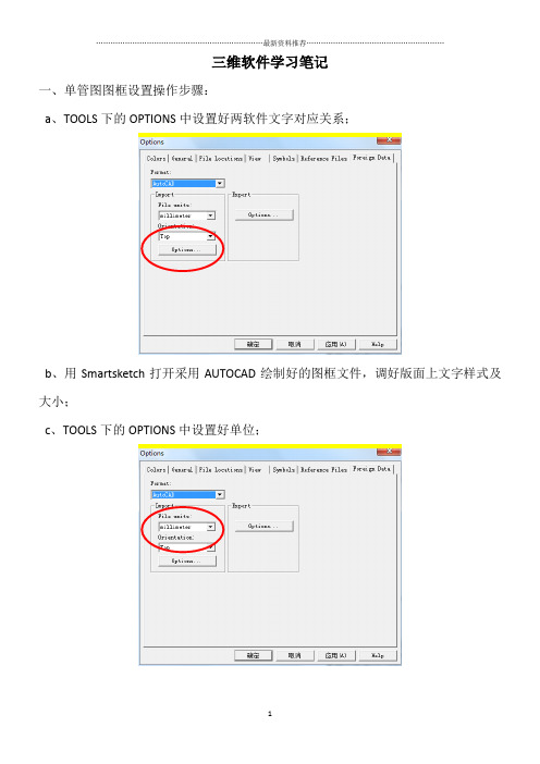
三维软件学习笔记一、单管图图框设置操作步骤:a、TOOLS下的OPTIONS中设置好两软件文字对应关系;b、用Smartsketch打开采用AUTOCAD绘制好的图框文件,调好版面上文字样式及大小;c、TOOLS下的OPTIONS中设置好单位;d、在VIEWS下选择BACKGROUD SHEETS,设置好对应大小的SHEET SETTUP,然后将图框复制过去;e、然后切换至WORKING SHEETS,新建对应大小的SHEET SETTUP此步Name下必须修改为SHEET1f、在SHEET下保存文件为.SHA文件。
g、在下面路径中找到\Program Files(x86)\Smart3D\CatalogData\Bulkload\Datafiles找到bulkloadisokeys.xls文件,打开复制一列,将名称全部对应修改为要添加的图框名称。
采用BULKLOAD下。
h、将a-f步骤创建的图框拷在项目共享文件\\win-v6n6pvm43e2\SharedContent\PmfgIsoStyleData下,然后拷一个相应大小的XML 文件,(COOKTOP2.5打开)将该XML文件中的图框名字对应修改为新建图框的名字,然后保存。
I、ISOGEN设置时,文字报错,修改文字设置如下。
j 、在DRAWING AND REPORTS 模式下新建ISO 文件夹,然后在ISO 文件夹下新建如下图的内容,k 、存储风格包,如下图,选择SAVE Package 。
选择下面的pipelinel、选中新建的风格包,右键选SETUP,新建Filter时选择好处图范围,如下图。
m、然后选中风格包,右键新建图纸,如下图,最后UPDATE NOW即可完成ISO图出图。
备注:平面图图框二、PID中项目备份及恢复操作步骤;a、项目备份:首先打开SMARTPLANT ENGINEERING MANAGER,然后选择具体项目,在TOOLS下选择BACKS,操作步骤如下图。
SP3D在管道设计中的常见错误提示与解决方案
SP3D在管道设计中的常见错误提示与解决方案1. 引言1.1 SP3D在管道设计中的重要性使用SP3D进行管道设计不仅可以提高设计效率,减少设计时间,还可以降低设计成本,提升设计质量。
通过SP3D软件,工程师们可以方便地进行管道布局、管道连接、管道直径选择等工作,减少出现错误的可能性。
SP3D还可以帮助工程师们进行管道模拟、管道分析等工作,提前发现潜在问题,保证工程项目的顺利进行。
SP3D在管道设计中的重要性不言而喻。
只有充分发挥SP3D的功能优势,结合工程师们的经验和技能,才能更好地完成管道设计工作,为工程项目的成功实施提供坚实的保障。
2. 正文2.1 常见SP3D错误提示及解决方法在使用SP3D进行管道设计过程中,常常会遇到各种错误提示,下面是一些常见的错误提示及解决方法:错误提示1:管道不存在解决方法:首先要确认所选管道是否确实存在于模型中,可以通过查看管道列表或者在模型中进行搜索来确认。
如果管道确实存在但仍提示不存在,可以尝试重新加载模型或者重新选择管道进行操作。
错误提示2:管道直径不允许为0解决方法:这个错误提示通常是由于参数设置不正确导致的。
需要检查管道直径参数是否填写正确,如果不正确则修改为合适的数值。
也需要确认管道的材质和规格是否符合设计要求。
错误提示3:管道连接错误解决方法:当遇到管道连接错误时,首先要检查管道的连接点是否对齐并且连接端口是否正确。
如果连接点对齐但仍然有错误提示,可以尝试重新连接管道或者检查管道的连接设置是否正确。
错误提示4:坐标点无效解决方法:这个错误提示通常是由于坐标点设置错误导致的。
需要确认所选坐标点是否在合理范围内,并且坐标点是否与管道连接点匹配。
如果坐标点无效,可以尝试重新设置坐标或者更改坐标点的位置。
通过了解这些常见的SP3D错误提示及解决方法,可以帮助设计工程师更快地解决问题,提高工作效率。
2.2 错误提示1:管道不存在常见SP3D错误提示及解决方法当在SP3D软件中遇到“管道不存在”的错误提示时,通常是由于管道在设计过程中未正确连接或者被误删除导致的。
Tekla Structures与SmartPlant3D连接流程

Tekla Structures与SmartPlant3D连接流程文件12月20日, 2007 Michael Gustafson, Tekla Inc.目的这个文档的目的是定义整合Tekla Structures(TS)和SmartPlant(SP3D)的范围和步骤流程。
内容基础并且包括了可以应用到工业领域多个学科比如能源和核工业的许多好的实践经验。
要注意的是,这个文档仅是一个指导文件,我们推荐用户根据自己的需要进行一些自行的设置。
流程范围第一阶段的工作通常基于将结构节点从Tekla Structures转换到SP3D。
这一流程的范围是延伸扩展TS和SP3D的持续整合。
数据转换的方法第一阶段的数据主要转换方法是CIS/2(CIMSteel2),这种格式是钢结构领域非常普通的格式,并且它的应用已经延伸到了混凝土结构的线性构件(开口的混凝土板、墙板)。
未来阶段TS和SP3D之间的发展很可能延伸到以例如CIS2作为数据转换办法的STEP。
第二种数据转换的格式是DGN(或DWG),DGN可以用来导入所有不包括在CIS/2的格式的对象参考模型。
阶段I –从Tekla输出数据并且输入到SmartPlant (V7-SP2) 用户有几个可行的流程来合作。
其中的2个流程如下方所示,描述的是他们和民用的或使用Tekla Structures的结构工程师或使用SP3D的机械/电力/管道工程师相互之间的关系。
流程 1 下面的示意图1就是流程1的概念图。
示意图 1 –任务向导流程1虽然在结构数据转换中有几个几个切入点,流程1还是集中将Tekla Structures的内容导入到SmartPlant产品中,这种数据转换通常是一个单向的流程;然而3-D协调和决策的参考对象从SmartPlant交换到Tekla是由结构团队来完成的。
这个流程的简单翻译就是包括在Tekla Structures(TS)中开始创建钢结构和混凝土对象。
SP3D RDB 操作手册
SP3D RDB 操作手册1.前期准备参考资料:PipingReferenceData.pdf1.1.选择制作等级的样板文件复制…\SmartPlant\3D\Workstation\CatalogData\BulkLoad\DataFiles中的AllCodeLists.xls、Piping Catalog.xls、Piping Specification.xls到新建文件夹,取消只读并改名,在这里我新建了一个SP3D RDB文件夹,并将上面三个文件改名为CodeLists_sample.xls、Piping Catalog_sample.xls、Piping Specification_sample.xls。
1.2.文档的用途CodeLists_sample.xls:定义等级制作中所需用到的codePiping Specification_sample.xls:定义管道等级规定的信息Piping Catalog_sample.xls:定义管道部件的尺寸信息1.3.制作等级需要的文件、文档管道材料等级表材料等级表中所涉及到的标准此处选择以制作成达项目中的B1C等级为例子2.CodeLists_sample.xls的制作CodeLists_sample.xls相当于PDS的Standard Note Library Manager中的各个Code表。
整理B1C等级中的尺寸标准号、管表号、流体代码、绝热材料、管道材料、压力、端面形式等,比对原先CodeLists_sample.xls中的GeometricIndustryStandard、ScheduleThickness、FluidCode、InsulationMaterial、MaterialsGrade、PressureRating、EndPreparation等工作表,如这些工作表中缺少相应的信息的话进行添加并编码。
以管表号为例,B1C中的管表号为CD-nn(nn代表数字及STD、XS、XXS),原先的ScheduleThickness中并没有,所以需要添加,我们添加在Company Standards层次下,编号从10001开始(编号不可重复),并在HEAD列添加A,结果如下:在CodeLists_sample.xls中标有颜色的sheets需要添加编码的可能性比较大在后期制作Piping Catalog.xls、Piping Specification.xls的时候还可能会遇到漏填的code,多人做表的时候记得code一定要统一。
SmartPlant3D结构专业操作手册1.1
SmartPlant3D结构专业操作⼿册1.1SmartPlant 3D结构专业⼊门⼿册(初版)主要⽬的:为结构专业建模⼈员提供⼊门帮助。
主要内容:⼀、初识SmartPlant 3D⼆、建⽴柱⽹三、建⽴模型四、绘制结构施⼯图如何使⽤:先阅读每节的简介,然后按照操作练习,完成上机操作,最后将会建⽴⼀框架的结构模型,⽣成⼀份图纸。
⼀、初识SmartPlant 3D1.SmartPlant 3D内容简介SmartPlant 3D(以下简称SP3D)是由intergraph公司开发的⼯⼚设计软件。
软件设置不同的Task,将⼯⼚设计中常⽤的专业进⾏分类,⽅便⽤户的使⽤。
软件中设置如下Task: Electrical, Common, Drawings and Reports, Equipment and Furnishings, Grids, Hangers and Supports, HVAC, Layout, Piping, Catalog, Space Management, Structural Analysis, Structure, Systems and Specifications.结构专业在使⽤时,经常⽤到的task有,Common, Drawings and Reports, Grids, Space Management, Structural Analysis, Structure。
其中Common 模块主要实现视图操作、定位、拷贝、粘贴等功能。
Common模块下的操作在其它模块下基本都可以实现。
Drawings and Reports模块能够实现出图和出报表,为满⾜不同公司的要求,图纸和报表⼀般需要定制。
本⼿册仅讲述如何在已经定制好的情况下,如何实现出图、报表⼯作。
Grids模块是柱⽹模块,⽤来定义结构柱⽹及标⾼。
Space Management是空间管理模块,定义Volume,实现出图。
- 1、下载文档前请自行甄别文档内容的完整性,平台不提供额外的编辑、内容补充、找答案等附加服务。
- 2、"仅部分预览"的文档,不可在线预览部分如存在完整性等问题,可反馈申请退款(可完整预览的文档不适用该条件!)。
- 3、如文档侵犯您的权益,请联系客服反馈,我们会尽快为您处理(人工客服工作时间:9:00-18:30)。
1 / 59
8. 测量 ................................................................................................................................ 28 9. 碰撞检查 ........................................................................................................................ 28 10. 出图及报表 .................................................................................................................. 29 volume drawing 同一立方体出不同视角图 ................................................... 29 drawing by datasheet query:出某一类物体的视图 ..................................... 33 snapshot drawing(composed drawing 的一种):拍照出图 ...................... 37 composed drawing:出组合图。即把不同对象的视图出在一张图上 .......... 39 导出三维模型或 DGN/CAD 文件 .................................................................... 43 出 ISO 图 ........................................................................................................... 47
SP3D 基本操作及功能介绍 一、安装软件、配置、进入模型 ..................................................................................... 3 安装 SP3D 2014: ................................................................................................................. 3 配置 SP3D 2014 ..................................................................................................................... 3 安装 SPLM 步骤: ................................................................................................................ 3 配置 SPLM: ......................................................................................................................... 4 运行 SP3D 2014 ..................................................................................................................... 4 二、界面介绍及常用设置................................................................................................. 7 界面介绍 ............................................................................................................................... 7 基本操作工具介绍 ............................................................................................................... 7 菜单栏设置介绍 ................................................................................................................. 10 edit 菜单 .......................................................................................................................... 10 view 菜单 ........................................................................................................................ 11 formate 菜单 ................................................................................................................... 12 tools 菜单 ........................................................................................................................ 14
task 菜单 ......................................................................................................................... 24 windows 菜单。可以多窗口操作。 .............................................................................. 24 三、常用的功能及操作介绍 ........................................................................................... 25 1. 查找 ................................................................................................................................பைடு நூலகம்25 2. 快速查找定位 ................................................................................................................ 25 3. 只想查看所选对象 ........................................................................................................ 26 4. 分层显示 ........................................................................................................................ 27 5. 保存视角 ........................................................................................................................ 27 6. 刷新保存获取最新工作 F5 ........................................................................................... 28 7. 缩放、旋转、平移等 .................................................................................................... 28
