maxon 电机资料 re-max 24
Rane Model DC 24 动态控制器说明书

DC 24DYNAMIC CONTROLLERData Sheet-1General DescriptionThe Rane Model DC 24 Dynamic Controller is a two chan-nel Compressor, Limiter, Expander Gate system with very un-usual attributes. The DC 24 offers unprecedented control of its operating parameters as well as a built-in 24 dB/octave Linkwitz-Riley Crossover which gives it very impressive capabilities.Total freedom from control interaction highlight the DC 24 as well as the availability of separate Compressor and Limiter controls. The Compressor offers control over both Ratio and Threshold, while the Limiter allows setting a separate Threshold. In doing this, the DC 24 allows the operator to create a smooth transition between subtle compression over a wide dynamic range and peak-stop limiting at the sound system’s highest allow-able level. If that’s not enough, the DC 24 also offers indepen-dent Expander/Gate Ratio and Threshold controls. This third level of signal manipulation makes the DC 24 a most useful and revolutionary device.Attack and release times are automatic and program depen-dent. This simplifies use of the DC 24, as these subtle controls can confuse most users. History has proven that experienced compressor users rarely miss these controls after using a DC 24.The internal Crossover allows the DC 24 to operate as a two-way speaker dividing network along with all of the dy-namic characteristics of a fully featured Compressor Limiter. In addition to this application, the DC 24 supplies the necessary circuitry to allow the unit to divide a single channel of audio information in two separate frequency ranges and to then re-combine the program material into one Channel. Using the DC 24 in this way eliminates the pumping and breathing associated with compression and limiting when only one Channel is used to cover the entire audio spectrum.Refer to “The DC 24 User’s Guide,” on the Rane website, for an easy-to-understand guide of operation and applications.Features• Ratio & Threshold Controls for Compressor and Gate/Expander • Limiter Threshold Controls• Program Dependent Attack & Release• Linkwitz-Riley Crossover with 24 dB per Octave Slopes • Low-High Crossover Mode (1 In/2 Out)• Bandsplit Combine Mode (1 In/1 Out)• Stereo/Dual Modes (2 In/2 Out)• Side Chain Insert Jacks• Balanced XLR & ¼" TRS Connectors • -10 dBV / +4 dBu Gain Switch• UL/CSA Remote Power Supply (120 VAC)• CE (Low Voltage & EMC) Remote Power Supply (230 VAC)DATA SHEETDC 24DYNAMIC CONTROLLERData Sheet-2Parameter Specification Limit Units Conditions/CommentsCompressor..........Threshold Range -50 to +205dB ..........Ratio Range 1:1 to 10:110%Expander / Gate..........Threshold Range -50 to +105dB ..........Ratio Range 1:1 to 20:110%Limiter..........Threshold Range -20 to +202dBCrossover ..........Type Linkwitz-Riley 4th-order 24 dB per octave slopes..........Range 70 Hz to 7 kHz5%41-detent continuously variable pot Inputs: Type Active Balanced / Unbalanced ..........Connectors XLR & + ¼" TRS ..........Impedance20k 1%Ω..........Maximum Level +201dBuOutputs: Type Active Balanced ..........Connectors XLR & + ¼" TRS ..........Impedance1001%ΩEach output ..........Maximum Level +261dBu 2 kΩ or greater +201dBu 600 Ω or greaterOverall Gain Range -12 to +12±1dB Center detent unity gainRFI FiltersYes Passive Bypass SwitchYes LED Thresholds: Overload +221dBu Output or any internal level ..........Signal Present -403dBu Input LevelFrequency Response 20 Hz to 20 kHz +0/-.5dB THD+Noise0.05.01%+4 dBu, 1 kHzIM Distortion (SMPTE)0.1.01%60 Hz / 7 kHz, 4:1, +4 dBuSignal-to-Noise Ratio 1082dB Unity Gain re +20 dBu, 20 kHz BW 922dBUnity Gain re +4 dBu, 20 kHz BW Unit: Agency Listing ..........120 VAC model Class 2 Equipment National Electrical Code UL & CSA Exempt Class 2 equipment ..........230 VAC model CE-EMC EMC directive 89/336/EECCE-SafetyExempt per art. 1, LVD 73/23/EEC Power Supply: Agency Listing Rane model RS 1Class 2 Equipment ..........120 VAC model UL File no. E88261CSA File no. LR58948..........230 VAC modelCE-EMC EMC directive 89/336/EEC CE-Safety LV directive 73/23/EEC ..........100 VAC model Built to JISJapan onlyPower Supply Requirement 18 VAC w/center tap 0.1Vrms Maximum Current 600mA RMS current from remote supply Unit: Construction All Steel..........Size 1.75"H x 19"W x 5.3"D (1U)(4.4 cm x 48.3 cm x 13.5 cm) ..........Weight 5 lb(2.3 kg)Shipping: Size 4.5" x 20.3" x 13.75"(11.5 cm x 52 cm x 35 cm)..........Weight 9 lb(4.1 kg)Note 1: 0 dBu=0.775 VrmsNote 2: Unless otherwise stated, all measurements made with Thresholds set at maximum, Ratios set at minimum.DC 24DYNAMIC CONTROLLERData Sheet-3Block DiagramArchitectural SpecificationsThe dynamic processor shall be a two (2) channel unit, each channel of which provides independent control over its gating, compression and limiting functions. The gating function shall provide a means for setting the gate threshold as well as the ratio of the function thus providing a means for gentler slopes to oc-cur such as one would expect to find in an expander.The compressor shall also provide a means for setting thresh-old and ratio independently. The limiter shall also provide a means for setting its operational threshold, but shall differ from the other two functions in that limit ratio shall be a function of limit level.All attack and release characteristics provided by the dynam-ic controller shall be a function of the current program material, thus providing a high level of transparency to the listener.The dynamic processor shall provide an active crossover circuit for the purpose of using the unit to drive amplifiers con-nected to two-way loudspeaker systems as well as for dividing a single channel audio source into two frequency bands for ulti-mate recombination at the outupts of the device. The crossover shall be a fourth-order Linkwitz-Riley type configuration.Passive bypass switches shall be provided to ensure total bypass of the unit’s active circuitry in the event of power failure. The inputs and outputs shall be active balanced/unbalanced designs terminated with XLR & ¼" TRS connectors. The side-chain send and receive connectors shall be ¼" unbalanced types, wired tip=send, ring=return.RFI filters shall be provided at the processor’s inputs. LEDs shall be provided to indicate the presence of an input signal as well as high level overload conditions.The unit shall be exempt from agency safety requirements and powered from a UL listed / CSA certified remote power sup-ply (120 VAC), or CE approved (230 VAC) via a rear panel input modular plug.The unit shall be entirely constructed from cold-rolled steel, and mount into a standard EIA relay rack occupying 1 rack space.The unit shall be a Rane Corporation Model DC 24.DC 24DYNAMIC CONTROLLERData Sheet-4All features & specifications subject to change without notice.DOC 107501Rear PanelAvailable Accessories • SC 1.7 Security Cover©Rane Corporation 10802 47th Ave. W., Mukilteo WA 98275-5098 TEL 425-355-6000 FAX 425-347-7757 WEB Application InformationTraditionally, a product such as the DC 24 has been referred to as a “Compressor / Limiter” because the range of the Ratio control on the Compressor has been wide enough to accommo-date both gentle compression and harder limiting effects. Not, however, simultaneously. One had to make a choice between the two modes of operation. On some models a Gate has been pro-vided which may or may not be part of the Compressor function.In the DC 24, all three functions of each channel are inde-pendent. Gating may occur when low-level signals are present, compression may occur when the level increases, and “peak-stop” limiting is available for high-level signals. This provides a three slope capability which is rather unique in the audio industry.Additionally, the DC 24 can help out a great deal on the low end of the amplitude spectrum by serving as a noise gate simul-taneously. The Compressor may be used to “tighten” vocals and instrumentals while leaving the Limiter function available for use as a safety valve.To accomplish this feat, the DC 24 provides three separate “Side Chains” in each Channel, each having its own set of front panel controls. For the Gate / Expander function, input signal is converted from an audio format to a control signal and ap-plied to the threshold circuit. If the output of the controller is below the specified threshold, it is passed along to the Gate / Expander Ratio control. The Ratio control allows attenuation of the controller to inhibit the slope of the Expander. After this at-tenuation, the control signal is delivered to the Channel’s control summing amplifier where it will meet similar signals generated by the Compressor control system.The Compressor controller works remarkably similarly to the Gate, the exception being the polarity. While the Gate circuit reduces gain when input level decreases below Threshold, the Compressor decreases gain when input increases above Thresh-old. The Compressor also receives the output of the controller, applies it to its threshold determinator, and passes the signalto the ratio attenuator if threshold conditions are satisfied. The output of the Ratio control is applied to the summing amplifier referenced in the gate section.Side Chain inserts have been provided on the rear of the unit to allow the insertion of an equalizer into the control circuits of the Gate and the Compressor. This will allow the user to create a frequency-dependent threshold for the Gate and/or the Compressor. This feature is useful when attempting to control sibilance in vocals.The Limiter operates in an entirely different manner than the preceding sections. The control circuit for the Limiter monitors the output of the VCA, not the input of the unit. Anytime the output of the VCA exceeds the Threshold set on the front panel, Limiting begins to take place. The ratio of the Limiter is set automatically and is a function of the excess level the system is attempting to deliver above the preset Threshold. The attack and release time of the Limiter is a function of the speed at which the input signal is attempting to drive the output of the unit above the Threshold level.The Crossover function of the DC 24 is based on Rane’s time-proven 4th-order state-variable Linkwitz-Riley design. This yields a 24 dB per octave slope and an in-phase characteristic. Since the outputs are in phase with each other, they recombine properly when the channel summing mode is selected via the rear panel Separate/Combine switch.In its band-split mode, the DC 24 allows separate processing of low frequencies and high frequencies; a mode which makes its operation all the more transparent. When the Crossover is used in conjunction with a two-way loudspeaker system, adequate driver protection may be ensured while providing a very flexible means of program manipulation.For a better view of the various operational modes, refer to “The DC 24 Users Guide” RaneNote, from the Rane website.。
maxon电机选型手册

maxon电机选型⼿册1214400 13700 12800 13800 156 124 82.9 72.7 8250 7490 6960 8080 2.25 2.25 2.33 2.26 0.907 0.716 0.467 0.37 4.61 5.25 5.39 5.76 1.7 1.44 0.929 0.801 50 49 49 49 5 ... 15 5 ...15 5 ... 15 5 .. 。
15 3.06 3.87 6.21 7.73 3130 2470 1540 1230 2440 2580 2480 2510 10.9 11.6 11.1 11.3 0.428 0.428 0.428 0.428 14400-44700 11300-35200 6840-21800 5360-17400 1:120000 5000 10000 15000 2.0 1.0 2.0 4.0 6.0 6.0 320817 1.5 0.5 320816 320817 320818 320819 320817 23.5 -40…+ 85C + 100C maxonEC电机0.14mm,2014年5⽉版更改库存程序标准程序特殊程序要求)零件号规格⼯作范围注释[rpm]上⾯列出的连续运⾏热阻(连续运⾏最⼤)在此期间达到的最⾼允许绕组温度为25线环境温度25线(热极限)。
电动机的短期运⾏可能会暂时过载)Maxon指定的功率额定值模块化系统概述第20页25EC-max 16 2线制16毫⽶,⽆刷,⽡特额定电压标称电压标称电压负载速度rpm负载电流mA额定速度rpm标称转矩(最⼤连续转矩)mNm额定电流(最⼤连续电流)c恒定转矩mNm恒定电流最⼤效率特性35型控制36电源电压+ VCC 12转矩恒定mNm / A 13速度恒定rpm / V 14速度/转矩梯度rpm / mNm 15机械时间常数ms 16转⼦惯性gcm 39速度范围rpm热数据17热阻壳体环境18热阻绕组壳体的热时间常数19绕组的热时间常数20电动机21的环境温度最⾼22.温度电⼦(最⼤负载电⼦)机械数据(预紧球轴承)23转速20000 rpm 24轴向游隙轴向载荷25径向游隙预载荷26最⼤轴向载荷(动态)27最⼤静压⼒(最⼤)28径向载荷,mmrom法兰,其他规格,31重量,电机⽅向顺时针旋转(CW)列出的值标称连接(电缆AWG 26/7 UL Style 1569)红⾊+ VCC⿊⾊GND保护功能极性反接保护最⾼18 VDC锁定转⼦保护⼀节76rpm温度监控104C电流限制1.6 15%低压监控VDC注意:⼯作电压VCC 18VDC电⼦选项:逆时针⽅向旋转(CCW)⾏星减速机16 mm 0.1 0.3Nm Page 254电机数据控制受控受控Maxon Electric中国⼯程师常成⼗三⼗九个11900 11900 11900 11900 130 85.1 64.2 42.6 31.9 7120 7090 7300 7170 7350 7.66 7.8 8.02 7.87 8.19 1.76 1.17 0.909 0.593 0.461 19.2 19.8 21.1 20.3 22 4.17 2.82 2.27 1.45 1.17 69 69 70 70 71 1.44 3.19 5.3 12.4 20.5 0.0343 0.0793 0.14 0.317 0.566 4.61 7.02 9.32 14 18.7 2070 1360 1020 681510510646619582602556556 5.75 5.51 5.18 5.36 4.95 0.85 0.85 0.85 0.85 0.85 0.85 0.85 0.85 1:1283831 283832 283833 283834 283835 17.7-40…+ 10 0毫⽶ES36155C 0.14 EC 342 ESCON Mod。
明纬nes200-24说明书

明纬nes200-24说明书明纬NES200-24型号电源是一种高效率、高性能的交流至直流稳压电源,适用于工业自动化控制、机电设备、通信设备、仪器仪表等领域。
本文将介绍明纬NES200-24的技术参数、使用方法、安全注意事项以及维护保养等相关内容。
首先,明纬NES200-24的技术参数如下:- 输入电压:85-264VAC- 输出电压:24VDC- 额定输出电流:8.8A- 输出功率:211.2W- 效率:90%以上- 工作温度:-20℃~70℃- 保护功能:过载保护、过压保护、过热保护其次,使用明纬NES200-24的步骤如下:1. 在使用前,请确认输入电源的电压范围与明纬NES200-24的输入电压要求相匹配。
2. 将输入电源线连接到输入端子上,并确保连接牢固。
3. 将输出电源线连接到输出端子上,并确保连接正确。
4. 将明纬NES200-24的输出端子连接到需要供电的设备上。
5. 打开输入电源开关,开始供电。
在使用明纬NES200-24时,需要注意以下安全事项:1. 在使用本产品之前,请仔细阅读使用说明书,确保操作正确。
2. 请勿将本产品放置在潮湿、易燃、易爆、腐蚀性气体环境等有害环境中。
3. 请勿将本产品与其他高压电源连接,以免发生电击等危险。
4. 在操作本产品时,请勿私自拆卸、修理或改变产品结构。
5. 请勿超过本产品的额定电压和电流范围,以免损坏设备或造成安全事故。
最后,明纬NES200-24的维护保养主要包括以下几点:1. 定期清洁产品的散热孔,确保散热效果良好。
2. 如有异物进入产品,请立即断开电源,并将异物清除。
3. 定期检查产品的线缆和连接器是否松动,如有松动请及时拧紧。
4. 如发现产品有异常情况(如发热、异味等),请立即断开电源并联系售后服务。
总之,明纬NES200-24是一款性能稳定、安全可靠的交流至直流稳压电源。
使用时,务必按照说明书中的要求进行操作,并注意安全事项。
在正常使用过程中,定期进行维护保养,可以延长产品的使用寿命并确保其正常工作。
安浦鸣志步进伺服SSM24S-Q手册
Belimo EV24A-RE 2-way和3-way球值驱动器说明书
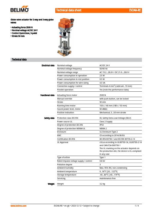
EV24A-REGlobe valve actuator for 2-way and 3-way globevalves• Actuating force 2500 N• Nominal voltage AC/DC 24 V• Control Open/close, 3-point• Stroke 50 mmTechnical dataElectrical data Nominal voltage AC/DC 24 VNominal voltage frequency50/60 HzNominal voltage range AC 19.2...28.8 V / DC 21.6...28.8 VPower consumption in operation 2.5 WPower consumption in rest position0.5 WPower consumption for wire sizing 4.5 VAConnection supply / control Terminals 4 mm² (cable ø4...10 mm)Parallel operation Yes (note the performance data)Functional data Actuating force motor2500 NManual override with push-button, can be lockedStroke50 mmRunning time motor150 s / 40 mm (188 s / 50 mm)Sound power level, motor56 dB(A)Position indication Mechanical, 5...50 mm strokeSafety data Protection class IEC/EN III, Safety Extra-Low Voltage (SELV)Power source UL Class 2 SupplyDegree of protection IEC/EN IP54Degree of protection NEMA/UL NEMA 2Enclosure UL Enclosure Type 2EMC CE according to 2014/30/EUCertification IEC/EN IEC/EN 60730-1 and IEC/EN 60730-2-14UL Approval cULus according to UL60730-1A, UL60730-2-14and CAN/CSA E60730-1The UL marking on the actuator depends onthe production site, the device is UL-compliantin any caseType of action Type 1Rated impulse voltage supply / control0.8 kVPollution degree3Ambient humidity Max. 95% RH, non-condensingAmbient temperature0...50°C [32...122°F]Storage temperature-40...80°C [-40...176°F]Servicing maintenance-freeWeight Weight 3.2 kgEV24A-RE••••••Safety notesThis device has been designed for use in stationary heating, ventilation and air-conditioning systems and must not be used outside the specified field of application, especially in aircraft or in any other airborne means of transport.Outdoor application: only possible in case that no (sea) water, snow, ice, insolation or aggressive gases interfere directly with the device and that it is ensured that the ambient conditions remain within the thresholds according to the data sheet at any time.Only authorised specialists may carry out installation. All applicable legal or institutional installation regulations must be complied with during installation.The switch for changing the direction of motion and so the closing point may be adjusted only by authorised specialists. The direction of motion is critical, particularly in connection with frost protection circuits.The device may only be opened at the manufacturer's site. It does not contain any parts that can be replaced or repaired by the user.The device contains electrical and electronic components and must not be disposed of as household refuse. All locally valid regulations and requirements must be observed.Product featuresMounting on third-party valvesThe RetroFIT+ actuators for installation on a wide range of valves from various manufacturers are comprised of an actuator, universal valve neck adapter and universal valve stem adapter. Adapt the valve neck and valve stem to begin with, then attach the RetroFIT+ actuator to the valve neck adapter, connect to the valve and start up. The valve neck adapter/actuator can be rotated by 360° on the valve neck, provided the size of the installed valve permits.Mounting on Belimo valvesUse standard actuators from Belimo for mounting on Belimo globe valves.Manual overrideManual override with push-button possible (the gear train is disengaged for as long as the button is pressed or remains locked).The stroke can be adjusted by using a hexagon socket screw key (5 mm), which is inserted into the top of the actuator. The stem extends when the key is rotated clockwise.High functional reliabilityThe actuator is overload protected, requires no limit switches and automatically stops when the end stop is reached.Home positionFactory setting: Actuator stem is retracted.Setting direction of motion When actuated, the stroke direction switch changes the running direction in normal operation.Restriction 3-point controllerIt must be ensured that the pulsating 3-point controller stops when the end position is reached. If this is not possible on the system side, the multifunctional 24 V version of the actuator (..V24A-MP-..) must be used.AccessoriesElectrical accessories DescriptionType Auxiliary switch 2x SPDT add-on S2A-H Mechanical accessoriesDescriptionType Spacer ring for Sauter, stroke 50 mm ZRV-301Spacer ring for Siebe, stroke 50 mmZRV-302Spacer ring for Johnson Control, stroke 50 mm ZRV-303Washer Sauter for Sauter, stroke 50 mmZRV-304EV24A-REElectrical installationSupply from isolating transformer.Parallel connection of other actuators possible. Observe the performance data.Direction of stroke switch factory setting: Actuator stem retracted (▲).Wiring diagramsAC/DC 24 V, open/close AC/DC 24 V, 3-pointOperating controls and indicators1Direction of stroke switchSwitch over:Direction of stroke changes4Manual override buttonPress button:Gear train disengages, motor stops, manual override possibleRelease button:Gear train engages, standard mode10Manual overrideClockwise:Actuator stem extendsCounterclockwise:Actuator stem retractsEV24A-RE DimensionsFurther documentation• Installation instructions for actuators。
Belimo NRF24A-SZ 旋转线性电机说明书
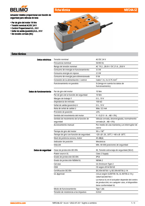
Actuador rotativo proporcional con función deseguridad para válvulas de bola • Par de giro del motor 10 Nm • Tensión nominal AC/DC 24 V • Control Proporcional 0.5...10 V • Señal de salida (posición) 0.5...10 V • Sin tensión cerrado (NC)Datos técnicosDatos eléctricosTensión nominal AC/DC 24 V Frecuencia nominal 50/60 HzRango de tensión nominalAC 19.2...28.8 V / DC 21.6...28.8 V Consumo de energía en funcionamiento 3.5 W Consumo energía en reposo2.5 W Consumo de energía para dimensionado 6 VAConexión de la alimentación / control Cable 1 m, 4 x 0.75 mm²Funcionamiento en paraleloSi (tenga en cuenta los datos de funcionamiento)Datos de funcionamiento Par de giro del motor10 Nm Par de giro de la función de seguridad 10 Nm Margen de trabajo Y 0.5...10 V Impedancia de entrada 100 kΩSeñal de salida (posición) U 0.5...10 V Nota de señal de salida U Máx. 0,5 mA Precisión de posición±5%Sentido del movimiento del motor Y = 0 (0 V = A – AB = 0%)Sentido de movimiento de la función de seguridadVálvula cerrada, desenergizada, normalmente cerrada (A – AB = 0%)Accionamiento manual Por medio de una manivela y un interruptor de cierre Tiempo de giro del motor90 s / 90°Tiempo de giro con función de seguridad <20 s @ -20...50°C / <60 s @ -30°C Nivel de potencia sonora, motor 45 dB(A)Indicador de posición MecánicosVida útilMín. 60 000 posiciones de seguridad Datos de seguridad Clase de protección IEC/EN III, Tensión extra-baja de seguridad (SELV)Power source ULClass 2 Supply Grado de protección IEC/EN IP54Grado de protección NEMA/UL NEMA 2Carcasa UL Enclosure Type 2CEMCE según 2014/30/UECertificación IEC/EN IEC/EN 60730-1 y IEC/EN 60730-2-14UL ApprovalcULus según UL60730-1A, UL 60730-2-14 y CAN/CSA E60730-1La marca UL en el actuador depende del centro de producción; en cualquier caso, el dispositivo tiene conformidad UL Modo de funcionamientoTipo 1.AA Tensión de resistencia a los impulsos0.8 kV••••••Modo de funcionamientoMontaje directo y sencillo Accionamiento manualÁngulo de giro ajustableAlta fiabilidad funcionalDatos de seguridadGrado de polución 3Humedad ambiente Máx. 95% de RH, sin condensación Temperatura ambiente-30...50°C [-22...122°F]Temperatura de almacenamiento -40...80°C [-40...176°F]Mantenimientosin mantenimiento PesoPeso 2.0 kgNotas de seguridadEste dispositivo ha sido diseñado para su uso en sistemas estacionarios de calefacción,ventilación y aire acondicionado y no se debe utilizar fuera del campo específico de aplicación, especialmente en aviones o en cualquier otro tipo de transporte aéreo.Aplicación en exterior: sólo es posible en el caso de que el dispositivo no esté expuestodirectamente a agua (de mar), nieve, hielo, radiación solar o gases nocivos y que se asegure que las condiciones ambientales se mantienen en todo momento dentro de los umbrales de acuerdo con la ficha de datos.Sólo especialistas autorizados deben realizar la instalación. Durante la instalación, deberán cumplirse todas las regulaciones de instalación legales o institucionales que correspondan.El dispositivo sólo se puede abrir en el centro del fabricante. No contiene piezas que el usuario pueda reemplazar o reparar.No se deben retirar los cables del dispositivo.El dispositivo contiene componentes eléctricos y electrónicos y no se puede desechar con los residuos domésticos. Deben tenerse en cuenta todas las normas y requerimientos locales vigentes.Características del productoEl actuador se conecta con una señal de control estándar de 0...10 V. El actuador mueve la válvula hasta la posición de funcionamiento al mismo tiempo que tensa el muelle de retorno. Cuando se interrumpe la alimentación, la fuerza del muelle hace girar de nuevo la válvula hasta la posición de seguridad.Montaje directo sencillo en la válvula de bola con tan solo un tornillo. Se puede seleccionar la orientación de montaje con respecto a la válvula de bola en incrementos de 90°.Al utilizar la manivela, la válvula se puede manejar de forma manual y engranarse con el contacto de bloqueo en cualquier posición. El desbloqueo se lleva a cabo de forma manual o automática aplicando tensión.Ángulo de giro ajustable mediante topes mecánicos.El actuador se encuentra protegido contra sobrecargas, no necesita ningún contacto limitador y se detiene automáticamente cuando alcanza el final de carrera.Instalación eléctricaAlimentación del transformador de aislamiento de seguridad.Es posible realizar una conexión en paralelo de otros actuadores. Respete los datos de funcionamiento.Esquema de conexionadoAC/DC 24 V, proporcionalColores de cables:1 = negro2 = rojo3 = blanco5 = naranjaDimensionesDocumentación complementaria• La gama de productos completa para aplicaciones de agua• Fichas de datos para válvulas de bola• Instrucciones de instalación para actuadores o válvulas de bola• Notas generales para la planificación de proyectos。
maxon motor ESCON伺服控制器设置说明书
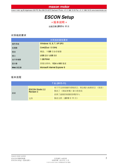
ESCON Setup«版本说明»出版日期 2015年11月对系统的要求版本流程对系统的最低要求操作系统Windows 10, 8, 7, XP SP3处理器Core2Duo 1.5 GHz 驱动硬盘,1 GB 空余存储器接口USB 2.0 / USB 3.0运行存储器1 GB RAM 显示器屏幕分辨率:1024 x 600像素Web 浏览器Microsoft Internet Explorer 87版 (2015-11)改动ESCON Studio 2.2Revision 3对于不支持的操作系统语言,将会载入标准语言(英语)修改了《调试参数》窗口的布局改善了虚拟控制器的参数导入文件修改文档(2015年11月)特征参数ESCON Studio 2.2新增针对伺服控制器ESCON Module 24/2的支持功能引入了针对转速/电流设定值、偏移和电流限制的RCServo信号输入(PWM脉冲时间)新功能也包括可以通过模拟输入调节变速ESCON Module 24/2发布文档:– 固件版本《读我》文件(2014年11月)– 功能表(2014年11月)– 使用说明书(2014年11月)改动ESCON Studio 2.2优化了无传感器EC电机的“调试参数”性能和稳定性普遍改善ESCON 36/2 DCESCON 36/3 ECESCON Module 50/4 EC-SESCON 50/5ESCON Module 50/5ESCON 70/10ESCON固件0x0150的升级软件修改文档:– 固件版本《读我》文件(2014年11月)– 使用说明书(2014年11月)5特征参数ESCON Studio 2.1还支持伺服控制器ESCON Module 50/4 EC-S扩展了«数据记录»工具ESCON Module 50/4 EC-S启用ESCON固件0x0140的升级软件启用的文档:– 固件版本的«读我»文件(2013年9月)– 功能列表(2013年9月)– 使用说明书(2013年9月)改动ESCON Studio 2.1性能和稳定性普遍改善ESCON 36/2 DCESCON 36/3 ECESCON 50/5ESCON Module 50/5ESCON 70/10ESCON固件0x0140的升级软件修改的文档:– 固件版本的«读我»文件(2013年9月)– 使用说明书(2013年9月)4 2改动ESCON Studio 2.0Revision 2修正了«使能:顺时针» 和 «使能:逆时针» 的设置问题特征参数ESCON Studio 2.0还支持ESCON 70/10伺服控制器及ESCON Module 50/5引入了«虚拟控制器»选项(配置上不考虑伺服控制器)引入了«电流检定仪»扩展了«数据记录»工具ESCON Module 50/5ESCON 70/10启用ESCON固件0x0130的升级软件启用的文档:– 固件版本的«读我»文件(2013年3月)– 功能列表(2013年3月)– 使用说明书(2013年3月)改动ESCON Studio 2.0性能和稳定性普遍改善表达方面稍有调整ESCON 36/2 DCESCON 36/3 ECESCON 50/5ESCON固件0x0130的升级软件修改的文档:– 固件版本的«读我»文件(2013年3月)– 使用说明书(2013年3月)32改动ESCON 36/3 EC文档的加工:–使用说明书(2012年10月)3特征参数ESCON Studio 1.2还支持伺服控制器ESCON 36/3 EC支持其他语言:日语(ja)、中文(zh)引入«诊断»助理引入«数据记录»工具ESCON 36/3 ECESCON固件0x0120的升级软件文档的加工:–固件版本的«读我文件»(2012年9月)–功能列表(2012年9月)–使用说明书(2012年9月)改动ESCON 36/2 DCESCON 50/5ESCON固件0x0120的升级软件文档的加工:–固件版本的«读我文件»(2012年9月)–使用说明书(2012年9月)商标和商标所有者·Core2Duo™; © Intel Corporation, USA-Santa Clara, CA·Windows®, Internet Explorer®; © Microsoft Corporation, USA-Redmond, WA 特征参数ESCON Studio 1.1还支持伺服控制器ESCON 50/5支持其他语言:意大利语(it )、西班牙语(es )引入«启动辅助»内的接线总览引入«控制器监控»、总览和特征参数ESCON 50/5ESCON 固件0x0110的升级软件文档的加工:–固件版本的«读我文件»(2012年3月)–功能列表(2012年3月)–使用说明书(2012年3月)改动ESCON 36/2 DC ESCON 固件0x0110的升级软件文档的加工:–固件版本的«读我文件»(2012年3月)–使用说明书(2012年3月)11改动ESCON Studio 1.0Revision 2点击操作元件图标时«控制器监控»不会死机。
MAX242EPN中文资料
General DescriptionThe MAX220–MAX249 family of line drivers/receivers is intended for all EIA/TIA-232E and V.28/V.24 communica-tions interfaces, particularly applications where ±12V is not available.These parts are especially useful in battery-powered sys-tems, since their low-power shutdown mode reduces power dissipation to less than 5µW. The MAX225,MAX233, MAX235, and MAX245/MAX246/MAX247 use no external components and are recommended for appli-cations where printed circuit board space is critical.________________________ApplicationsPortable Computers Low-Power Modems Interface TranslationBattery-Powered RS-232 Systems Multidrop RS-232 Networks____________________________Features Superior to Bipolaro Operate from Single +5V Power Supply (+5V and +12V—MAX231/MAX239)o Low-Power Receive Mode in Shutdown (MAX223/MAX242)o Meet All EIA/TIA-232E and V.28 Specifications o Multiple Drivers and Receiverso 3-State Driver and Receiver Outputs o Open-Line Detection (MAX243)Ordering InformationOrdering Information continued at end of data sheet.*Contact factory for dice specifications.MAX220–MAX249+5V-Powered, Multichannel RS-232Drivers/Receivers________________________________________________________________Maxim Integrated Products 1Selection Table19-4323; Rev 9; 4/00Power No. of NominalSHDN RxPart Supply RS-232No. of Cap. Value & Three-Active in Data Rate Number (V)Drivers/Rx Ext. Caps (µF)State SHDN (kbps)FeaturesMAX220+52/24 4.7/10No —120Ultra-low-power, industry-standard pinout MAX222+52/2 4 0.1Yes —200Low-power shutdownMAX223 (MAX213)+54/54 1.0 (0.1)Yes ✔120MAX241 and receivers active in shutdown MAX225+55/50—Yes ✔120Available in SOMAX230 (MAX200)+55/04 1.0 (0.1)Yes —120 5 drivers with shutdownMAX231 (MAX201)+5 and2/2 2 1.0 (0.1)No —120Standard +5/+12V or battery supplies; +7.5 to +13.2same functions as MAX232MAX232 (MAX202)+52/24 1.0 (0.1)No —120 (64)Industry standardMAX232A+52/240.1No —200Higher slew rate, small caps MAX233 (MAX203)+52/20— No —120No external capsMAX233A+52/20—No —200No external caps, high slew rate MAX234 (MAX204)+54/04 1.0 (0.1)No —120Replaces 1488MAX235 (MAX205)+55/50—Yes —120No external capsMAX236 (MAX206)+54/34 1.0 (0.1)Yes —120Shutdown, three stateMAX237 (MAX207)+55/34 1.0 (0.1)No —120Complements IBM PC serial port MAX238 (MAX208)+54/44 1.0 (0.1)No —120Replaces 1488 and 1489MAX239 (MAX209)+5 and3/52 1.0 (0.1)No —120Standard +5/+12V or battery supplies;+7.5 to +13.2single-package solution for IBM PC serial port MAX240+55/54 1.0Yes —120DIP or flatpack package MAX241 (MAX211)+54/54 1.0 (0.1)Yes —120Complete IBM PC serial port MAX242+52/240.1Yes ✔200Separate shutdown and enableMAX243+52/240.1No —200Open-line detection simplifies cabling MAX244+58/104 1.0No —120High slew rateMAX245+58/100—Yes ✔120High slew rate, int. caps, two shutdown modes MAX246+58/100—Yes ✔120High slew rate, int. caps, three shutdown modes MAX247+58/90—Yes ✔120High slew rate, int. caps, nine operating modes MAX248+58/84 1.0Yes ✔120High slew rate, selective half-chip enables MAX249+56/1041.0Yes✔120Available in quad flatpack packageFor free samples & the latest literature: , or phone 1-800-998-8800.For small orders, phone 1-800-835-8769.M A X 220–M A X 249+5V-Powered, Multichannel RS-232Drivers/ReceiversABSOLUTE MAXIMUM RATINGS—MAX220/222/232A/233A/242/243ELECTRICAL CHARACTERISTICS—MAX220/222/232A/233A/242/243(V CC = +5V ±10%, C1–C4 = 0.1µF‚ MAX220, C1 = 0.047µF, C2–C4 = 0.33µF, T A = T MIN to T MAX ‚ unless otherwise noted.)Note 1:Input voltage measured with T OUT in high-impedance state, SHDN or V CC = 0V.Note 2:For the MAX220, V+ and V- can have a maximum magnitude of 7V, but their absolute difference cannot exceed 13V.Stresses beyond those listed under “Absolute Maximum Ratings” may cause permanent damage to the device. These are stress ratings only, and functional operation of the device at these or any other conditions beyond those indicated in the operational sections of the specifications is not implied. Exposure to absolute maximum rating conditions for extended periods may affect device reliability.Supply Voltage (V CC )...............................................-0.3V to +6V Input VoltagesT IN ..............................................................-0.3V to (V CC - 0.3V)R IN (Except MAX220)........................................................±30V R IN (MAX220).....................................................................±25V T OUT (Except MAX220) (Note 1).......................................±15V T OUT (MAX220)...............................................................±13.2V Output VoltagesT OUT ...................................................................................±15V R OUT .........................................................-0.3V to (V CC + 0.3V)Driver/Receiver Output Short Circuited to GND.........Continuous Continuous Power Dissipation (T A = +70°C)16-Pin Plastic DIP (derate 10.53mW/°C above +70°C)....842mW 18-Pin Plastic DIP (derate 11.11mW/°C above +70°C)....889mW20-Pin Plastic DIP (derate 8.00mW/°C above +70°C)..440mW 16-Pin Narrow SO (derate 8.70mW/°C above +70°C)...696mW 16-Pin Wide SO (derate 9.52mW/°C above +70°C)......762mW 18-Pin Wide SO (derate 9.52mW/°C above +70°C)......762mW 20-Pin Wide SO (derate 10.00mW/°C above +70°C)....800mW 20-Pin SSOP (derate 8.00mW/°C above +70°C)..........640mW 16-Pin CERDIP (derate 10.00mW/°C above +70°C).....800mW 18-Pin CERDIP (derate 10.53mW/°C above +70°C).....842mW Operating Temperature RangesMAX2_ _AC_ _, MAX2_ _C_ _.............................0°C to +70°C MAX2_ _AE_ _, MAX2_ _E_ _..........................-40°C to +85°C MAX2_ _AM_ _, MAX2_ _M_ _.......................-55°C to +125°C Storage Temperature Range.............................-65°C to +160°C Lead Temperature (soldering, 10sec).............................+300°CMAX220–MAX249+5V-Powered, Multichannel RS-232Drivers/Receivers_______________________________________________________________________________________3Note 3:MAX243 R2OUT is guaranteed to be low when R2IN is ≥0V or is floating.ELECTRICAL CHARACTERISTICS—MAX220/222/232A/233A/242/243 (continued)(V= +5V ±10%, C1–C4 = 0.1µF‚ MAX220, C1 = 0.047µF, C2–C4 = 0.33µF, T = T to T ‚ unless otherwise noted.)M A X 220–M A X 249+5V-Powered, Multichannel RS-232Drivers/Receivers 4_________________________________________________________________________________________________________________________________Typical Operating CharacteristicsMAX220/MAX222/MAX232A/MAX233A/MAX242/MAX243108-1051525OUTPUT VOLTAGE vs. LOAD CURRENT-4-6-8-2642LOAD CURRENT (mA)O U T P U T V O L T A G E (V )1002011104104060AVAILABLE OUTPUT CURRENTvs. DATA RATE65798DATA RATE (kbits/sec)O U T P U T C U R R E N T (m A )203050+10V-10VMAX222/MAX242ON-TIME EXITING SHUTDOWN+5V +5V 0V0V 500µs/div V +, V - V O L T A G E (V )MAX220–MAX249+5V-Powered, Multichannel RS-232Drivers/Receivers_______________________________________________________________________________________5V CC ...........................................................................-0.3V to +6V V+................................................................(V CC - 0.3V) to +14V V-............................................................................+0.3V to -14V Input VoltagesT IN ............................................................-0.3V to (V CC + 0.3V)R IN ......................................................................................±30V Output VoltagesT OUT ...................................................(V+ + 0.3V) to (V- - 0.3V)R OUT .........................................................-0.3V to (V CC + 0.3V)Short-Circuit Duration, T OUT ......................................Continuous Continuous Power Dissipation (T A = +70°C)14-Pin Plastic DIP (derate 10.00mW/°C above +70°C)....800mW 16-Pin Plastic DIP (derate 10.53mW/°C above +70°C)....842mW 20-Pin Plastic DIP (derate 11.11mW/°C above +70°C)....889mW 24-Pin Narrow Plastic DIP(derate 13.33mW/°C above +70°C)..........1.07W24-Pin Plastic DIP (derate 9.09mW/°C above +70°C)......500mW 16-Pin Wide SO (derate 9.52mW/°C above +70°C).........762mW20-Pin Wide SO (derate 10 00mW/°C above +70°C).......800mW 24-Pin Wide SO (derate 11.76mW/°C above +70°C).......941mW 28-Pin Wide SO (derate 12.50mW/°C above +70°C) .............1W 44-Pin Plastic FP (derate 11.11mW/°C above +70°C).....889mW 14-Pin CERDIP (derate 9.09mW/°C above +70°C)..........727mW 16-Pin CERDIP (derate 10.00mW/°C above +70°C)........800mW 20-Pin CERDIP (derate 11.11mW/°C above +70°C)........889mW 24-Pin Narrow CERDIP(derate 12.50mW/°C above +70°C)..............1W24-Pin Sidebraze (derate 20.0mW/°C above +70°C)..........1.6W 28-Pin SSOP (derate 9.52mW/°C above +70°C).............762mW Operating Temperature RangesMAX2 _ _ C _ _......................................................0°C to +70°C MAX2 _ _ E _ _...................................................-40°C to +85°C MAX2 _ _ M _ _ ...............................................-55°C to +125°C Storage Temperature Range.............................-65°C to +160°C Lead Temperature (soldering, 10sec).............................+300°CABSOLUTE MAXIMUM RATINGS—MAX223/MAX230–MAX241ELECTRICAL CHARACTERISTICS—MAX223/MAX230–MAX241(MAX223/230/232/234/236/237/238/240/241, V CC = +5V ±10; MAX233/MAX235, V CC = 5V ±5%‚ C1–C4 = 1.0µF; MAX231/MAX239,V CC = 5V ±10%; V+ = 7.5V to 13.2V; T A = T MIN to T MAX ; unless otherwise noted.)Stresses beyond those listed under “Absolute Maximum Ratings” may cause permanent damage to the device. These are stress ratings only, and functional operation of the device at these or any other conditions beyond those indicated in the operational sections of the specifications is not implied. Exposure to absolute maximum rating conditions for extended periods may affect device reliability.M A X 220–M A X 249+5V-Powered, Multichannel RS-232Drivers/Receivers 6_______________________________________________________________________________________ELECTRICAL CHARACTERISTICS—MAX223/MAX230–MAX241 (continued)(MAX223/230/232/234/236/237/238/240/241, V CC = +5V ±10; MAX233/MAX235, V CC = 5V ±5%‚ C1–C4 = 1.0µF; MAX231/MAX239,V CC = 5V ±10%; V+ = 7.5V to 13.2V; T A = T MIN to T MAX ; unless otherwise noted.)MAX220–MAX249+5V-Powered, Multichannel RS-232Drivers/Receivers_______________________________________________________________________________________78.56.54.55.5TRANSMITTER OUTPUT VOLTAGE (V OH ) vs. V CC7.08.0V CC (V)V O H (V )5.07.57.46.02500TRANSMITTER OUTPUT VOLTAGE (V OH )vs. LOAD CAPACITANCE AT DIFFERENT DATA RATES6.46.27.27.0LOAD CAPACITANCE (pF)V O H (V )1500100050020006.86.612.04.02500TRANSMITTER SLEW RATE vs. LOAD CAPACITANCE6.05.011.09.010.0LOAD CAPACITANCE (pF)S L E W R A T E (V /µs )1500100050020008.07.0-6.0-9.04.55.5TRANSMITTER OUTPUT VOLTAGE (V OL ) vs. V CC-8.0-8.5-6.5-7.0V CC (V)V O L (V )5.0-7.5-6.0-7.62500TRANSMITTER OUTPUT VOLTAGE (V OL )vs. LOAD CAPACITANCE AT DIFFERENT DATA RATES-7.0-7.2-7.4-6.2-6.4LOAD CAPACITANCE (pF)V O L (V )150010005002000-6.6-6.810-105101520253035404550TRANSMITTER OUTPUT VOLTAGE (V+, V-)vs. LOAD CURRENT-2-6-4-886CURRENT (mA)V +, V - (V )420__________________________________________Typical Operating CharacteristicsMAX223/MAX230–MAX241*SHUTDOWN POLARITY IS REVERSED FOR NON MAX241 PARTSV+, V- WHEN EXITING SHUTDOWN(1µF CAPACITORS)MAX220-13SHDN*V-O V+500ms/divM A X 220–M A X 249+5V-Powered, Multichannel RS-232Drivers/Receivers 8_______________________________________________________________________________________ABSOLUTE MAXIMUM RATINGS—MAX225/MAX244–MAX249ELECTRICAL CHARACTERISTICS—MAX225/MAX244–MAX249(MAX225, V CC = 5.0V ±5%; MAX244–MAX249, V CC = +5.0V ±10%, external capacitors C1–C4 = 1µF; T A = T MIN to T MAX ; unless oth-erwise noted.)Note 4:Input voltage measured with transmitter output in a high-impedance state, shutdown, or V CC = 0V.Stresses beyond those listed under “Absolute Maximum Ratings” may cause permanent damage to the device. These are stress ratings only, and functional operation of the device at these or any other conditions beyond those indicated in the operational sections of the specifications is not implied. Exposure to absolute maximum rating conditions for extended periods may affect device reliability.Supply Voltage (V CC )...............................................-0.3V to +6V Input VoltagesT IN ‚ ENA , ENB , ENR , ENT , ENRA ,ENRB , ENTA , ENTB ..................................-0.3V to (V CC + 0.3V)R IN .....................................................................................±25V T OUT (Note 3).....................................................................±15V R OUT ........................................................-0.3V to (V CC + 0.3V)Short Circuit (one output at a time)T OUT to GND............................................................Continuous R OUT to GND............................................................ContinuousContinuous Power Dissipation (T A = +70°C)28-Pin Wide SO (derate 12.50mW/°C above +70°C).............1W 40-Pin Plastic DIP (derate 11.11mW/°C above +70°C)...611mW 44-Pin PLCC (derate 13.33mW/°C above +70°C)...........1.07W Operating Temperature RangesMAX225C_ _, MAX24_C_ _ ..................................0°C to +70°C MAX225E_ _, MAX24_E_ _ ...............................-40°C to +85°C Storage Temperature Range.............................-65°C to +160°C Lead Temperature (soldering,10sec)..............................+300°CMAX220–MAX249+5V-Powered, Multichannel RS-232Drivers/Receivers_______________________________________________________________________________________9Note 5:The 300Ωminimum specification complies with EIA/TIA-232E, but the actual resistance when in shutdown mode or V CC =0V is 10M Ωas is implied by the leakage specification.ELECTRICAL CHARACTERISTICS—MAX225/MAX244–MAX249 (continued)(MAX225, V CC = 5.0V ±5%; MAX244–MAX249, V CC = +5.0V ±10%, external capacitors C1–C4 = 1µF; T A = T MIN to T MAX ; unless oth-erwise noted.)M A X 220–M A X 249+5V-Powered, Multichannel RS-232Drivers/Receivers 10________________________________________________________________________________________________________________________________Typical Operating CharacteristicsMAX225/MAX244–MAX24918212345TRANSMITTER SLEW RATE vs. LOAD CAPACITANCE86416LOAD CAPACITANCE (nF)T R A N S M I T T E R S L E W R A T E (V /µs )14121010-105101520253035OUTPUT VOLTAGEvs. LOAD CURRENT FOR V+ AND V--2-4-6-88LOAD CURRENT (mA)O U T P U T V O L T A G E (V )64209.05.012345TRANSMITTER OUTPUT VOLTAGE (V+, V-)vs. LOAD CAPACITANCE AT DIFFERENT DATA RATES6.05.58.5LOAD CAPACITANCE (nF)V +, V (V )8.07.57.06.5MAX220–MAX249Drivers/Receivers______________________________________________________________________________________11Figure 1. Transmitter Propagation-Delay Timing Figure 2. Receiver Propagation-Delay TimingFigure 3. Receiver-Output Enable and Disable Timing Figure 4. Transmitter-Output Disable TimingM A X 220–M A X 249Drivers/Receivers 12______________________________________________________________________________________ENT ENR OPERATION STATUS TRANSMITTERSRECEIVERS00Normal Operation All Active All Active 01Normal Operation All Active All 3-State10Shutdown All 3-State All Low-Power Receive Mode 11ShutdownAll 3-StateAll 3-StateTable 1a. MAX245 Control Pin ConfigurationsENT ENR OPERATION STATUS TRANSMITTERS RECEIVERSTA1–TA4TB1–TB4RA1–RA5RB1–RB500Normal Operation All Active All Active All Active All Active 01Normal Operation All Active All Active RA1–RA4 3-State,RA5 Active RB1–RB4 3-State,RB5 Active 1ShutdownAll 3-StateAll 3-StateAll Low-Power Receive Mode All Low-Power Receive Mode 11Shutdown All 3-State All 3-StateRA1–RA4 3-State,RA5 Low-Power Receive ModeRB1–RB4 3-State,RB5 Low-Power Receive ModeTable 1b. MAX245 Control Pin ConfigurationsTable 1c. MAX246 Control Pin ConfigurationsENA ENB OPERATION STATUS TRANSMITTERS RECEIVERSTA1–TA4TB1–TB4RA1–RA5RB1–RB500Normal Operation All Active All Active All Active All Active 01Normal Operation All Active All 3-State All Active RB1–RB4 3-State,RB5 Active 1ShutdownAll 3-StateAll ActiveRA1–RA4 3-State,RA5 Active All Active 11Shutdown All 3-State All 3-StateRA1–RA4 3-State,RA5 Low-Power Receive ModeRB1–RB4 3-State,RA5 Low-Power Receive ModeMAX220–MAX249Drivers/Receivers______________________________________________________________________________________13Table 1d. MAX247/MAX248/MAX249 Control Pin ConfigurationsM A X 220–M A X 249_______________Detailed DescriptionThe MAX220–MAX249 contain four sections: dual charge-pump DC-DC voltage converters, RS-232 dri-vers, RS-232 receivers, and receiver and transmitter enable control inputs.Dual Charge-Pump Voltage ConverterThe MAX220–MAX249 have two internal charge-pumps that convert +5V to ±10V (unloaded) for RS-232 driver operation. The first converter uses capacitor C1 to dou-ble the +5V input to +10V on C3 at the V+ output. The second converter uses capacitor C2 to invert +10V to -10V on C4 at the V- output.A small amount of power may be drawn from the +10V (V+) and -10V (V-) outputs to power external circuitry (see the Typical Operating Characteristics section),except on the MAX225 and MAX245–MAX247, where these pins are not available. V+ and V- are not regulated,so the output voltage drops with increasing load current.Do not load V+ and V- to a point that violates the mini-mum ±5V EIA/TIA-232E driver output voltage when sourcing current from V+ and V- to external circuitry. When using the shutdown feature in the MAX222,MAX225, MAX230, MAX235, MAX236, MAX240,MAX241, and MAX245–MAX249, avoid using V+ and V-to power external circuitry. When these parts are shut down, V- falls to 0V, and V+ falls to +5V. For applica-tions where a +10V external supply is applied to the V+pin (instead of using the internal charge pump to gen-erate +10V), the C1 capacitor must not be installed and the SHDN pin must be tied to V CC . This is because V+is internally connected to V CC in shutdown mode.RS-232 DriversThe typical driver output voltage swing is ±8V when loaded with a nominal 5k ΩRS-232 receiver and V CC =+5V. Output swing is guaranteed to meet the EIA/TIA-232E and V.28 specification, which calls for ±5V mini-mum driver output levels under worst-case conditions.These include a minimum 3k Ωload, V CC = +4.5V, and maximum operating temperature. Unloaded driver out-put voltage ranges from (V+ -1.3V) to (V- +0.5V). Input thresholds are both TTL and CMOS compatible.The inputs of unused drivers can be left unconnected since 400k Ωinput pull-up resistors to V CC are built in (except for the MAX220). The pull-up resistors force the outputs of unused drivers low because all drivers invert.The internal input pull-up resistors typically source 12µA,except in shutdown mode where the pull-ups are dis-abled. Driver outputs turn off and enter a high-imped-ance state—where leakage current is typically microamperes (maximum 25µA)—when in shutdownmode, in three-state mode, or when device power is removed. Outputs can be driven to ±15V. The power-supply current typically drops to 8µA in shutdown mode.The MAX220 does not have pull-up resistors to force the ouputs of the unused drivers low. Connect unused inputs to GND or V CC .The MAX239 has a receiver three-state control line, and the MAX223, MAX225, MAX235, MAX236, MAX240,and MAX241 have both a receiver three-state control line and a low-power shutdown control. Table 2 shows the effects of the shutdown control and receiver three-state control on the receiver outputs.The receiver TTL/CMOS outputs are in a high-imped-ance, three-state mode whenever the three-state enable line is high (for the MAX225/MAX235/MAX236/MAX239–MAX241), and are also high-impedance whenever the shutdown control line is high.When in low-power shutdown mode, the driver outputs are turned off and their leakage current is less than 1µA with the driver output pulled to ground. The driver output leakage remains less than 1µA, even if the transmitter output is backdriven between 0V and (V CC + 6V). Below -0.5V, the transmitter is diode clamped to ground with 1k Ωseries impedance. The transmitter is also zener clamped to approximately V CC + 6V, with a series impedance of 1k Ω.The driver output slew rate is limited to less than 30V/µs as required by the EIA/TIA-232E and V.28 specifica-tions. Typical slew rates are 24V/µs unloaded and 10V/µs loaded with 3Ωand 2500pF.RS-232 ReceiversEIA/TIA-232E and V.28 specifications define a voltage level greater than 3V as a logic 0, so all receivers invert.Input thresholds are set at 0.8V and 2.4V, so receivers respond to TTL level inputs as well as EIA/TIA-232E and V.28 levels.The receiver inputs withstand an input overvoltage up to ±25V and provide input terminating resistors withDrivers/Receivers 14Table 2. Three-State Control of ReceiversMAX220–MAX249Drivers/Receivers______________________________________________________________________________________15nominal 5k Ωvalues. The receivers implement Type 1interpretation of the fault conditions of V.28 and EIA/TIA-232E.The receiver input hysteresis is typically 0.5V with a guaranteed minimum of 0.2V. This produces clear out-put transitions with slow-moving input signals, even with moderate amounts of noise and ringing. The receiver propagation delay is typically 600ns and is independent of input swing direction.Low-Power Receive ModeThe low-power receive-mode feature of the MAX223,MAX242, and MAX245–MAX249 puts the IC into shut-down mode but still allows it to receive information. This is important for applications where systems are periodi-cally awakened to look for activity. Using low-power receive mode, the system can still receive a signal that will activate it on command and prepare it for communi-cation at faster data rates. This operation conserves system power.Negative Threshold—MAX243The MAX243 is pin compatible with the MAX232A, differ-ing only in that RS-232 cable fault protection is removed on one of the two receiver inputs. This means that control lines such as CTS and RTS can either be driven or left floating without interrupting communication. Different cables are not needed to interface with different pieces of equipment.The input threshold of the receiver without cable fault protection is -0.8V rather than +1.4V. Its output goes positive only if the input is connected to a control line that is actively driven negative. If not driven, it defaults to the 0 or “OK to send” state. Normally‚ the MAX243’s other receiver (+1.4V threshold) is used for the data line (TD or RD)‚ while the negative threshold receiver is con-nected to the control line (DTR‚ DTS‚ CTS‚ RTS, etc.). Other members of the RS-232 family implement the optional cable fault protection as specified by EIA/TIA-232E specifications. This means a receiver output goes high whenever its input is driven negative‚ left floating‚or shorted to ground. The high output tells the serial communications IC to stop sending data. To avoid this‚the control lines must either be driven or connected with jumpers to an appropriate positive voltage level.Shutdown—MAX222–MAX242On the MAX222‚ MAX235‚ MAX236‚ MAX240‚ and MAX241‚ all receivers are disabled during shutdown.On the MAX223 and MAX242‚ two receivers continue to operate in a reduced power mode when the chip is in shutdown. Under these conditions‚ the propagation delay increases to about 2.5µs for a high-to-low input transition. When in shutdown, the receiver acts as a CMOS inverter with no hysteresis. The MAX223 and MAX242 also have a receiver output enable input (EN for the MAX242 and EN for the MAX223) that allows receiver output control independent of SHDN (SHDN for MAX241). With all other devices‚ SHDN (SH DN for MAX241) also disables the receiver outputs.The MAX225 provides five transmitters and five receivers‚ while the MAX245 provides ten receivers and eight transmitters. Both devices have separate receiver and transmitter-enable controls. The charge pumps turn off and the devices shut down when a logic high is applied to the ENT input. In this state, the supply cur-rent drops to less than 25µA and the receivers continue to operate in a low-power receive mode. Driver outputs enter a high-impedance state (three-state mode). On the MAX225‚ all five receivers are controlled by the ENR input. On the MAX245‚ eight of the receiver out-puts are controlled by the ENR input‚ while the remain-ing two receivers (RA5 and RB5) are always active.RA1–RA4 and RB1–RB4 are put in a three-state mode when ENR is a logic high.Receiver and Transmitter EnableControl InputsThe MAX225 and MAX245–MAX249 feature transmitter and receiver enable controls.The receivers have three modes of operation: full-speed receive (normal active)‚ three-state (disabled)‚ and low-power receive (enabled receivers continue to function at lower data rates). The receiver enable inputs control the full-speed receive and three-state modes. The transmitters have two modes of operation: full-speed transmit (normal active) and three-state (disabled). The transmitter enable inputs also control the shutdown mode. The device enters shutdown mode when all transmitters are disabled. Enabled receivers function in the low-power receive mode when in shutdown.M A X 220–M A X 249Tables 1a–1d define the control states. The MAX244has no control pins and is not included in these tables. The MAX246 has ten receivers and eight drivers with two control pins, each controlling one side of the device. A logic high at the A-side control input (ENA )causes the four A-side receivers and drivers to go into a three-state mode. Similarly, the B-side control input (ENB ) causes the four B-side drivers and receivers to go into a three-state mode. As in the MAX245, one A-side and one B-side receiver (RA5 and RB5) remain active at all times. The entire device is put into shut-down mode when both the A and B sides are disabled (ENA = ENB = +5V).The MAX247 provides nine receivers and eight drivers with four control pins. The ENRA and ENRB receiver enable inputs each control four receiver outputs. The ENTA and ENTB transmitter enable inputs each control four drivers. The ninth receiver (RB5) is always active.The device enters shutdown mode with a logic high on both ENTA and ENTB .The MAX248 provides eight receivers and eight drivers with four control pins. The ENRA and ENRB receiver enable inputs each control four receiver outputs. The ENTA and ENTB transmitter enable inputs control four drivers each. This part does not have an always-active receiver. The device enters shutdown mode and trans-mitters go into a three-state mode with a logic high on both ENTA and ENTB .The MAX249 provides ten receivers and six drivers with four control pins. The ENRA and ENRB receiver enable inputs each control five receiver outputs. The ENTA and ENTB transmitter enable inputs control three dri-vers each. There is no always-active receiver. The device enters shutdown mode and transmitters go into a three-state mode with a logic high on both ENTA and ENTB . In shutdown mode, active receivers operate in a low-power receive mode at data rates up to 20kbits/sec.__________Applications InformationFigures 5 through 25 show pin configurations and typi-cal operating circuits. In applications that are sensitive to power-supply noise, V CC should be decoupled to ground with a capacitor of the same value as C1 and C2 connected as close as possible to the device.Drivers/Receivers16______________________________________________________________________________________。
MAXON电机
MAXON电机
MAXON齿轮箱、MAXON编码器、MAXON马达、MAXON减速箱、MAXON电机、MAXON驱动器、MAXON
上海秋腾贸易有限公司优惠供应瑞士MAXON电机,Maxon motor是一家瑞士公司,总部位于瑞士中部城市Sachseln,在全世界范围拥有1500名员工。
公司在30多个国家建立了良好的本土化的销售服务体系。
Maxon motor在总部瑞士、德国和匈牙利都设有生产线。
Maxon motor为诸多领域提供了具有价格竞争力的创新解决方案,如工业自动化、医疗技术、安全技术、仪器仪表、通讯技术、日用消费等领域。
maxon A-max系列电机是高品质直流电机的革命,它装有强力的铝镍钴永磁体,电机的核心部件-空心杯转子-已经过了百万次的测试。
这是将最新技术应用于结构紧凑、大功率、小惯量的电机制造中。
空芯杯转子
6 种尺寸的电机型号: ? 12, 16, 19, 22, 26, 32 mm
0.5 - 20 watts
特性:
高性能AlNiCo 磁钢
自动化生产有效降低了成本
机械换向器(石墨和稀有金属电刷)
出色的体积功率比
最高效能
低感量
无齿槽效应
小惯量转子实现高加速性能
低电磁串扰
优良的线性特性
高可靠性
可与减速箱,反馈部件和驱动控制器组成各种各样的伺服系统。
maxon 电机 escon module 50 4 ec-s 使用说明书
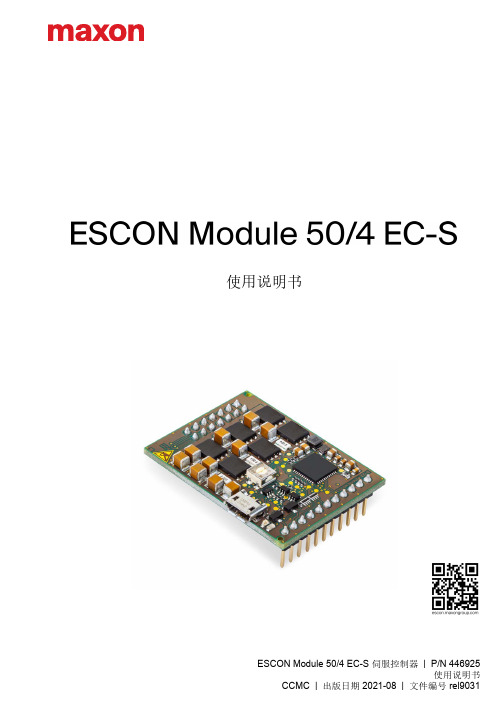
ESCON Module 50/4 EC-S 伺服控制器 | P/N 446925使用说明书CCMC | 出版日期 2021-08 | 文件编号 rel9031使用说明书目录ESCON Module 50/4 EC-S 使用说明书A-2CCMC | 2021-08 | rel90311概述51.1关于本说明书. . . . . . . . . . . . . . . . . . . . . . . . . . . . . 51.2设备介绍. . . . . . . . . . . . . . . . . . . . . . . . . . . . . . . 71.3安全规程. . . . . . . . . . . . . . . . . . . . . . . . . . . . . . . 82技术规格92.1技术数据. . . . . . . . . . . . . . . . . . . . . . . . . . . . . . . 92.2标准. . . . . . . . . . . . . . . . . . . . . . . . . . . . . . . . . 123设置133.1适用的一般规定. . . . . . . . . . . . . . . . . . . . . . . . . . . . 133.2起动方法. . . . . . . . . . . . . . . . . . . . . . . . . . . . . . . 143.3电源的设计. . . . . . . . . . . . . . . . . . . . . . . . . . . . . . 153.4接口. . . . . . . . . . . . . . . . . . . . . . . . . . . . . . . . . 163.5电位器. . . . . . . . . . . . . . . . . . . . . . . . . . . . . . . . 243.6状态显示. . . . . . . . . . . . . . . . . . . . . . . . . . . . . . . 254接线275母板设计指南(MOTHERBOARD DESIGN GUIDE)295.1对其他供应商组件的要求. . . . . . . . . . . . . . . . . . . . . . . . 295.2设计指令. . . . . . . . . . . . . . . . . . . . . . . . . . . . . . . 325.3THT Footprint . . . . . . . . . . . . . . . . . . . . . . . . . . . . . . . . . . . . . . . . . . . . . . . . . . . 325.4接口配置. . . . . . . . . . . . . . . . . . . . . . . . . . . . . . . 325.5技术数据. . . . . . . . . . . . . . . . . . . . . . . . . . . . . . . 335.6尺寸图. . . . . . . . . . . . . . . . . . . . . . . . . . . . . . . . 33目录请首先认真阅读下文本说明供有资质的专业技术人员阅读参考。
Maxon-DC motor-EC motor-麦克逊直流,交流电动机

maxon DC motor and maxon EC motor Key informationThe motor as an energy converterThe electrical motor converts electrical power P el (current I and voltage U) into mechanical power P mech (speed n and torque M). The losses that arise are divided into frictional losses, attributable to P mech and in Joule power losses P J of the winding (resistance R). Iron losses do not occur in the coreless maxon DC motors. In maxon EC motors, they are treated formally like an additional friction torque. The power balance can therefore be formulated as:The detailed result is as followsElectromechanical motor constantsThe geometric arrangement of the magnetic circuit and winding defi nes in detail how the motor converts the electrical input power (current, voltage) into mechanical output power (speed, torque). Two important characte-ristic values of this energy conversion are the speed constant k n and the torque constant k M . The speed constant combines the speed n with the voltage induced in the winding U ind (=EMF). U ind is proportional to the speed; the following applies:Similarly, the torque constant links the mechanical torque M with the electrical current I .The main point of this proportionality is that torque and current are equivalent for the maxon motor.The current axis in the motor diagrams is therefore shown as parallel to the torque axis as well.See also: Technology – short and to the point, explanation of the motorMotor diagramsA diagram can be drawn for every maxon DC and EC motor, from whichkey motor data can be taken. Although tolerances and temperature infl uences are not taken into consideration, the values are suffi cient for a fi rst estimation in most applications. In the diagram, speed n , current I ,power output P 2 and efficiency η are applied as a function of torque M at constant voltage U .Speed-torque lineThis curve describes the mechanical behavior of the motor at a constant voltage U :– Speed decreases linearly with increasing torque.– The faster the motor turns, the less torque it can provide.The curve can be described with the help of the two end points, no-load speed n 0 and stall torque M H (cf. lines 2 and 7 in the motor data).DC motors can be operated at any voltage. No-load speed and stalltorque change proportionally to the applied voltage. This is equivalent to a parallel shift of the speed-torque line in the diagram. Between the no-load speed and voltage, the following proportionality applies in good approxi-mationwhere k n is the speed constant (line 13 of the motor data).Independent of the voltage, the speed-torque line is described most prac-tically by the slope or gradient of the curve (line 14 of the motor data).m a x o n m oThe speed-torque gradient is one of the most informative pieces of data and allows direct comparison between different motors. The smaller the speed-torque gradient, the less sensitive the speed reacts to torque (load) changes and the stronger the motor. With the maxon motor, the speed-torque gradient within the winding series of a motor type (i.e. on one catalog page) remains practically constant.Current gradientThe equivalence of current to torque is shown by an axis parallel to the torque: more current fl owing through the motor produces more torque. The current scale is determined by the two points no-load current I 0 and starting current I A (lines 3 and 8 of motor data).The no-load current is equivalent to the friction torque M R , that describes the internal friction in the bearings and commutation system.In the maxon EC motor, there are strong, speed dependent iron losses in the stator iron stack instead of friction losses in the commutation system. The motors develop the highest torque when starting. It is many times greater than the normal operating torque, so the current uptake is the greatest as well.The following applies for the stall torque M H and starting current I AEffi ciency curve The effi ciency η describes the relationship of mechanical power delivered to electrical power consumed.One can see that at constant applied voltage U and due to the proportio-nality of torque and current, the effi ciency increases with increasing speed (decreasing torque). At low torques, friction losses become increasingly signifi cant and effi ciency rapidly approaches zero. Maximum effi ciency (line 9 of motor data) is calculated using the starting current and no-load current and is dependent on voltage.A rule of thumb is that maximum effi ciency occurs at roughly one seventh of the stall torque. This means that maximum effi ciency and maximum output power do not occur at the same torque.Rated working pointThe rated working point is an ideal working point for the motor and derives from operation at nominal voltage U N (line 1 of motor data) and nominal current I N (line 6). The nominal torque M N produced (line 5) in this working point follows from the equivalence of torque and current, and nominal speed n N (line 4) is reached in line with the speed gradient. The choice of nominal voltage follows from considerations of where the maximum no-load speed should be. The nominal current derives from the motor‘sthermally maximum permissible continuous current.Motor diagrams, operating rangesThe catalogue contains a diagram of every maxon DC and EC motor type that shows the operating ranges of the different winding types using a typical motor.Permanent operating rangeThe two criteria “maximum continuous torque” and “maximum permis- si-ble speed” limit the continuous operating range. Operating points within this range are not critical thermally and do not generally cause increased wear of the commutation system.Short-term operating rangeThe motor may only be loaded with the maximum continuous currentfor thermal reasons. However, temporary higher currents (torques) are allowed. As long as the winding temperature is below the critical value, the winding will not be damaged. Phases with increased currents are time li-mited. A measure of how long the temporary overload can last is provided by the thermal time constant of the winding (line 19 of the motor data). The magnitude of the times with overload ranges from several secondsfor the smallest motors (6 mm to 13 mm diameter) up to roughly one minute for the largest (60 mm to 90 mm diameter). The calculation of the exact overload time is heavily dependent on the motor current and the rotor’s starting temperature.Maximum continuous current, maximum continuous torqueThe Jule power losses heat up the winding. The heat produced must be able to dissipate and the maximum rotor temperature (line 22 of the motor data) should not be exceeded. This results in a maximum continuouscurrent Icont , at which the maximum winding temperature is attained understandard conditions (25°C ambient temperature, no heat dissipation via the fl ange, free air circulation). Higher motor currents cause excessive winding temperatures.The nominal current is selected so that it corresponds to this maximum permissible constant current. It depends heavily on the winding. These thin wire windings have lower nominal current levels than thick ones. With very low resistive windings, the brush system‘s capacity can further limit the permissible constant current. With graphite brush motors, friction losses increase sharply at higher speeds. With EC motors, eddy current losses increase in the return as speed increases and produce additional heat. The maximum permissible continuous current decreases at faster speeds accordingly. The nominal torque allocated to the nominal current is almost constant within a motor type‘s winding range and represents a characteristic size of the motor type.The maximum permissible speedfor DC motors is primarily limited by the commutation system. The commutator and brushes wear more rapidly at very high speeds.The reasons are:– Increased mechanical wear because of the large traveled path of the commutator– Increased electro-erosion because of brush vibration and spark formation.A further reason for limiting the speed is the rotor’s residual mechanical imbalance which shortens the service life of the bearings. Higher speedsthan the limit speed nmax (line 23) are possible, however, they are “paid for”by a reduced service life expectancy. The maximum permissible speed for the EC motor is calculated based on service life considerations of the ball bearings (at least 20000 hours) at the maximum residual imbalance and bearing load.Maximum winding temperatureThe motor current causes the winding to heat up due to the winding’s re-sistance. To prevent the motor from overheating, this heat must dissipate to the environment via the stator. The coreless winding is the thermally critical point. The maximum rotor temperature must not be exceeded, even temporarily. With graphite brush motors and EC motors which tend to have higher current loads, the maximum rotor temperature is 125°C (in individual cases up to 155°C). Motors with precious metal commutators only allow lower current loads, so that the rotor temperatures must not exceed 85°C. Favourable mounting conditions, such as good air circulati-on or cooling plates, can signifi cantly lower temperatures.nmaxon fl at motorMultipole EC motors, such as maxon fl at motors, require a greater number of commutation steps for a motor revolution (6 x number of pole pairs). Due to the wound stator teeth they have a higher terminal inductance than motors with an ironless winding. As a result at higher speed, the current cannot develop fully during the correspondingly short commutation inter-vals. Therefore, the apparent torque produced is lower. Current is also fed back into the controller‘s power stage.As a result, motor behaviour deviates from the ideal linear speed-torque gradient. The apparent speed-torque gradient depends on voltage and speed: The gradient is steeper at higher speeds.Mostly, fl at motors are operated in the continuous operation range where the achievable speed-torque gradient at nominal voltage can be appro-ximated by a straight line between no-load speed and nominal working point. The achievable speed-torque gradient is approximately.AccelerationIn accordance with the electrical boundary conditions (power supply, control, battery), a distinction is principally made between two different starting processes:– Start at constant voltage (without current limitation)– Start at constant current (with current limitation)Start under constant currentA current limit always means that the motor can only deliver a limited torque. In the speed-torque diagram, the speed increases on a vertical line with a constant torque. Acceleration is also constant, thus simplifying the calculation. Start at constant current is usually found in applications with servo amplifi ers, where acceleration torques are limited by the amplifi er‘s peak current.– Angular acceleration α (in rad / s2) at constant current I or constant torque M with an additional load of inertia JL:– Run-up time Δt (in ms) at a speed change Δn with an additional load inertia JL:(all variables in units according to the catalog)TolerancesTolerances must be considered in critical ranges. The possible deviations of the mechanical dimensions can be found in the overview drawings. The motor data are average values: the adjacent diagram shows the effect of tolerances on the curve characteristics. They are mainly caused by differences in the magnetic fi eld strength and in wire resistance, and not so much by mechanical infl uences. The changes are heavily exaggerated in the diagram and are simplifi ed to improve understanding. It is clear, however, that in the motor’s actual operating range, the tolerance range is more limited than at start or at no-load. Our computer sheets contain all detailed specifi cations.CalibratingThe tolerances can be limited by controlled de-magnetization of the motors. Motor data can be accurately specifi ed down to 1 to 3%.However, the motor characteristic values lie in the lower portion of the standard tolerance range.Thermal behaviorThe Joule power losses P J in the winding determine heating of the motor. This heat energy must be dissipated via the surfaces of the winding and motor. The increase ΔT W of the winding temperature T W with regard to the ambient temperature arises from heat losses P J and thermal resistances R th1 and R th2.Here, thermal resistance R th1 relates to the heat transfer between the win-ding and the stator (magnetic return and magnet), whereas R th2 describesthe heat transfer from the housing to the environment. Mounting themotor on a heat dissipating chassis noticeably lowers thermal resistance R th2. The values specifi ed in the data sheets for thermal resistances and the maximum continuous current were determined in a series of tests, in which the motor was end-mounted onto a vertical plastic plate. The mo-difi ed thermal resistance R th2 that occurs in a particular application must be determined using original installation and ambient conditions. Thermal resistance R th2 on motors with metal fl anges decreases by up to 50% if the motor is coupled to a good heat-conducting (e.g. metallic) retainer. The heating runs at different rates for the winding and stator due to the different masses. After switching on the current, the winding heats up fi rst (with time constants from several seconds to half a minute). The stator reacts much slower, with time constants ranging from 1 to 30 minutes depending on motor size. A thermal balance is gradually established. The temperature difference of the winding compared to the ambient tempe-rature can be determined with the value of the current I (or in intermittent operation with the effective value of the current I = I RMS ).Here, electrical resistance R must be applied at the actual ambient temperature.Infl uence of temperatureAn increased motor temperature affects winding resistance and ma-gnetic characteristic values.Winding resistance increases linearly according to the thermal resistance coeffi cient for copper:Example: a winding temperature of 75°C causes the winding resist- ance to increase by nearly 20%.The magnet becomes weaker at higher temperatures. The reduction is 1 to 10% at 75°C depending on the magnet material.The most important consequence of increased motor temperature is that the speed curve becomes steeper which reduces the stall torque. The changed stall torque can be calculated in fi rst approximation from the voltage and increased winding resistance.m a x o n m o t o rU,nExample for motor/gear selectionA drive should move cyclically in accordance with the following speed diagram.The inertia of load J L to be accelerated is 130000 gcm 2. The constant friction torque is 300 mNm. The motor is to be driven with the linear 4-Q servo amplifi er from maxon (LSC). The power supply delivers max.5 A and 24 V .Calculation of load dataThe torque required for acceleration and braking are calculated as follows (motor and gearhead inertia omitted):Together with the friction torque, the following torques result for the different phases of motion.– Acceleration phase (duration 0.5 s) 463 mNm – Constant speed (duration 2 s) 300 mNm – Braking (friction brakes with 300 mNm) (duration 0.5 s) 137 mNm – Standstill (duration 0.7 s) 0 mNm Peak torque occurs during acceleration.The RMS determined torque of the entire work cycle isThe maximum speed (60 rpm) occurs at the end of the acceleration phase at maximum torque (463 mNm). Thus, the peak mechanical power is:Regulated servo drivesIn work cycles, all operating points must lie beneath the curve at a ma-ximum voltage U max . Mathematically, this means that the following must apply for all operating points (n B , M B ):When using servo amplifi ers, a voltage drop occurs at the power stage, so that the effective voltage applied to the motor is lower. This must be taken into consideration when determining the maximum supply voltage U max . It is recommended that a regulating reserve of some 20% be included, so that regulation is even ensured with an unfavorable tolerance situation of motor, load, amplifi er and supply voltage. Finally, the average current load and peak current are calculated ensuring that the servo amplifi er used can deliver these currents. In some cases, a higher resistance winding must be selected, so that the currents are lower. However, the required voltage is then increased.Physical variables and their units SI Catalog i Gear reduction* I Motor current A A, mAI AStarting current* A A, mA I 0 No-load current* A mA I RMS RMS determined current A A, mA I N Nominal current* A A, mAJ RMoment of inertia of the rotor* kgm 2 gcm 2 J L Moment of inertia of the load kgm 2 gcm 2k M Torque constant* Nm/A mNm/A k n Speed constant* rpm/V M (Motor) torque Nm mNmM BOperating torque Nm mNm M H Stall torque* Nm mNm M mot Motor torque Nm mNm M R Moment of friction Nm mNmM RMSRMS determined torque Nm mNm M N Nominaltorque Nm mNm M N,G Max. torque of gear* Nm Nm n Speed rpm n B Operating speed rpmn maxLimit speed of motor* rpm n max,GLimit speed of gear* rpm n mot Motor speed rpm n 0 No-load speed* rpmP elElectrical power W W P JJoule power loss W W P mech Mechanical power W W R Terminal resistance Ω ΩR 25 Resistance at 25°C* Ω Ω R T Resistance at temperature T Ω ΩR th1Heat resistance winding housing* K/W R th2 Heat resistance housing/air* K/W t Time s s T Temperature K °CT maxMax. winding temperature* K °C T U Ambienttemperature K °C T W Winding temperature K °C U Motor voltage V V U ind Induced voltage (EMF) V VU maxMax. supplied voltage V V U N Nominal voltage* V V αCu Resistance coeffi cient of Cu αmax Maximum angle acceleration rad/s 2Δn/ΔM Curve gradient* rpm/mNm ΔT W T emperature difference winding/ambient K K Δt Run up time s ms η (Motor) effi ciency %ηG (Gear) effi ciency* %ηm ax Maximum effi ciency* %τm Mechanical time constant* s ms τS Therm. time constant of the stator* s s τW Therm. time constant of the winding* s s(*Specified in the motor or gear data)m a x o n m o t orGear selectionA gear is required with a maximum continuous torque of at least 0.28 Nm and an intermittent torque of at least 0.46 Nm. This requirement is fulfi lled, for example, by a planetary gear with 22 mm diameter (metal version).The recommended input speed of 6000 rpm allows a maximum reduction of:We select the three-stage gear with the next smallst reduction of 84 : 1 (stock program). Effi ciency is max. 59%.Motor type selectionSpeed and torque are calculated to the motor shaftThe possible motors, which match the selected gears in accordance with the maxon modular system, are summarized in the table opposite. The table only contains motors with graphite commutation which are better suited to start/stop operation.Selection falls on an A-max 22, 6 W, which demonstrates a suffi ciently high continuous torque. The motor should have a torque reserve so that it can even function with a somewhat unfavorable gear effi ciency. The additional torque requirement during acceleration can easily be delivered by the motor. The temporary peak torque is not even twice as high as the continuous torque of the motor.Selection of the windingThe motor type A-max 22, 6 W has an average speed-torque gradient of some 450 rpm/mNm. However, it should be noted that the two lowest resistance windings have a somewhat steeper gradient. The desired no-load speed is calculated as follows:The extreme working point should of course be used in the calculation (max. speed and max. torque), since the speed-torque line of the winding must run above all working points in the speed / torque diagram.This target no-load speed must be achieved with the maximum voltage U = 19 V supplied by the control (LSC), (voltage drop of the power amplifi er of the LSC 5 V), which defi nes the minimum target speed constant k n, theor of the motor.Based on the calculation, motor 110162 is chosen which corresponds to the winding with the next highest speed constant (689 rpm/V) and has a second shaft end for mounting the encoder. The winding’s higher speed constant compared to the target value means that the motor runs faster than required at 19 V which, however, can be compensated for by the controller. This selection also ensures that there is a speed regulating reserve of more than 20%. Thus, even unfavorable tolerances are not a problem.The torque constant of this winding is 13.9 mNm/A. The maximum torque corresponds to a peak current of:This current is lower than the maximum current (2 A) of the controller (LSC).Therefore, a gear motor combination has been found that fulfi lls therequirements (torque and speed) and can be operated with the controller provided.。
MORNSUN URF24_QB-100W(F H)R3 100W 广西科技有限公司 DC-DC 转

100W,wide input voltage,isolated ®ulatedsingleoutputDC-DC converterPatent Protection RoHSFEATURES●Ultra wide input voltage range (4:1)●High efficiency up to 90%●Isolation voltage:2.25K VDC●Input under-voltage protection,output short circuit,over-current,over–voltage,over-temperature protection●Operating temperature range:-40℃to +85℃●Five-sided metal shielding package ●International standard pin-out:1/4brick ●Meets requirements of railway standard EN50155URF24_QB -100W(F/H)R3series are isolated 100W DC-DC products with 4:1input voltage.They feature efficiency up to 90%,2250VDCisolation,operating temperature of -40℃to +85℃,Input under-voltage protection,output short circuit protection,over-current protection,over–voltage protection,over-temperature protection and EMI meets CISPR32/EN55032CLASS B,which make them widely applied in battery power supplies,industrial control,electricity,instruments,railway,communication fields.Selection GuidePart No.①Input Voltage (VDC)OutputEfficiency(%,Min./Typ.)@Full LoadMax.CapacitiveLoad(µF)Nominal (Range)Max.②Output Voltage(VDC)Output Current (A)(Max.)URF2405QB-100W(F/H)R324(9-36)4052087/896000URF2412QB-100W(F/H)R3128.388/902000URF2415QB-100W(F/H)R315 6.788/902000URF2424QB-100W(F/H)R324 4.288/901000URF2428QB-100W(F/H)R328 3.688/901000URF2448QB-100W(F/H)R3482.188/90470Note:①"F"means product with aluminium bottom case;Series with suffix “H”are heat sink mounting;If the application has a higher requirement for heat dissipation,you can choose modules with heat sink;②Exceeding the maximum input voltage may cause permanent damage.Input SpecificationsItemOperating Conditions Min.Typ.Max.Unit Input Current (full load/no-load)Nominal input voltage --4682/1204789/160mAReflected Ripple Current Nominal input voltage--30--Surge Voltage (1sec.max.)-0.7--50VDCStart-up Threshold Voltage ----9Input Under-voltage Protection 7.07.5--Input FilterPi filterCtrl *Module switch onCtrl open circuit or connected to TTL high level(3.5-12VDC)Module switch offCtrl pin connected to GND or low level(0-1.2VDC)Input current when switched off--265mAHot PlugUnavailableNote:*The voltage of Ctrl pin is relative to input pin GND.ItemOperating Conditions Min.Typ.Max.UnitOutput Voltage Accuracy 0%-100%load--±1±3%Line Regulation Full load,the input voltage is from low to high --±0.2±0.5Load Regulation 5%-100%load--±0.5±0.75Transient Recovery Time 25%load step change --200500µs Transient Response Deviation 25%load step change 5V output --±3±7.5%Others--±3±5Temperature Coefficient Full load----±0.03%/℃Ripple &Noise *20MHz bandwidth12V/15V output --100200mVp-p Others --130250Output Over-voltage Protection Input voltage range 110125160%Vo Output Over-current Protection 110125150%Io Short-circuit ProtectionHiccup,Continuous,self-recoveryNote:*Ripple and noise are measured by “parallel cable”method,please see DC-DC Converter Application Notes for specific operation.General SpecificationsItemOperating Conditions Min.Typ.Max.UnitInsulation Voltage Input-output With the test time of 1minute and the leak current less than 1mA2250----VDC Input-case 1600----Output-case500----Insulation Resistance Input-output,insulation voltage 500VDC 1000----M ΩIsolation Capacitance Input-output,100KHz/0.1V --2200--pF Trim *5V/15V output 91--110%Vo Others90--110Sense----110ThermocoupleURF24_QB-100WR3free convection ----8℃/W URF24_QB-100WFR3free convection ---- 6.8URF24_QB-100WHR3free convection ---- 5.7Operating Temperature -40--+85℃Storage Temperature -55--+125Over-temperature Protection95105115Pin Welding Resistance Temperature Wave-soldering,10seconds----260Welding spot is 1.5mm away from the casing,10seconds ----300Storage Humidity Non-condensing 5--95%RH VibrationIEC/EN61373car body 1B moldSwitching Frequency PWM mode--250--KHz MTBFMIL-HDBK-217F@25℃500----K hours Physical SpecificationsCasing MaterialAluminum alloy case,Black flame-retardant and heat-resistant plastic bottom case (UL94V-0)DimensionURF24xxQB-100WR361.8*40.2*12.7mm URF24xxQB-100WFR362.0*56.0*14.6mm URF24xxQB-100WHR361.8*40.2*27.7mm WeightURF24xxQB-100WR380g(Typ.)URF24xxQB-100WFR3100g(Typ.)URF24xxQB-100WHR3116(Typ.)Cooling methodNatural convection or Forced convectionEMICE CISPR32/EN55032,CLASS A and CLASS B (see Fig.3for recommended circuit)RE CISPR32/EN55032,CLASS A and CLASS B (see Fig.3for recommended circuit)EMSESDIEC/EN61000-4-2,Contact ±6KV Air ±8KV perf.Criteria B RS IEC/EN61000-4-3,20V/mperf.Criteria A EFT IEC/EN61000-4-4,±2KV(see Fig.2-1for recommended circuit)perf.Criteria A CSIEC/EN61000-4-6,10Vr.m.sperf.Criteria AEMC Specifications (EN50155)EMICEEN50121-3-2150kHz-500kHz 99dBuV (see Fig.3for recommended circuit)EN55016-2-1500kHz-30MHz 93dBuVRE EN50121-3-230MHz-230MHz 40dBuV/m at 10m (see Fig.3for recommended circuit)EN55016-2-1230MHz-1GHz 47dBuV/m at 10mEMSESD EN50121-3-2Contact ±6KV/Air ±8KV RSEN50121-3-220V/m(rms)EFT EN50121-3-2±2kV 5/50ns 5kHz (see Fig.2or Fig.2for recommended circuit)Surge EN50121-3-2line to line ±1KV (42Ω0.5uF see Fig.2for recommended circuit)CSEN50121-3-20.15MHz-80MHz 10V(rms)Product Characteristic CurveSense of application and precautions1.When not using remote sense0V+Vo sens e+Trim sens e-+C The lead as s hort as poss ibleLoadNotes :1)When not using remote sense,make sure +Vo and Sense +are shorted,and that 0V and Sense-are shorted as well;2)Keep the tracks between +Vo and Sense +,0V and Sense-as short as possible.and close to the terminal.Avoid a looping track.If noiseinterferes the loop,the operation of the power module will become unstable.2.When Remote Sense is used0V+Vo sens e+Trim sens e-Load+C Notes:ing remote sense with long wires may cause output voltage to become unstable.Consult us if long sensing wiring is necessary.2.Sense tracks or wires should be as short as possible.If using wires,it should not use twisted-pair or shielded wires.3.Please use wide PCB tracks or a thick wires between the power supply module and the load,the line voltage drop should be kept lessthan 0.3V.Make sure the power supply module's output voltage remains within the specified range.4.The impedance of wires may cause the output voltage oscillation or a greater ripple,please take adequate assessments before using.Design Reference1.Typical applicationIf not using Momsun’s recommended cicuit,please ensure an 220μF electrolytic capacitors in parallel with the input,which used to suppress the surge voltage come from the iuput terminal.All the DC/DC converters of this series are tested according to the recommended circuit (see Fig.1)before delivery.If it is required to further reduce input&output ripple,properly increase the input &output of additional capacitors Cin and Cout or select capacitors of low equivalent impedance,provided that the capacitance is no larger than the max.capacitive load of the product.DC DCVin G Vo0VCinCoutFuse Fig.1Vout(VDC)FuseCinCout 520A ,slow blow220µF470µF12/15220µF 24/28100µF 48100µF2.EMC solution-module recommended circuitFig.2device numberDevice parameter Device function C1150μF electrolyticcapacitor Meet puise groupand surgeC1147μF electrolyticcapacitor+Vin GND DC/DC+Vin +Vo0VGNDLOADCY3CY4CY1L2C1L1C2C3C4C5C6C7C8C9C10C11CY2+Fig.3CLASSA device numberCLASS B device number Device parameter Device functionC1150μF electrolytic capacitor Meet conducted emission and radiated emissionC1147μF electrolytic capacitor C2、C3、C4、C5、C6、C7、C8、C9、C1010μF ceramic capacitor L1、L21.6mH common mode inductorCY3CY1、CY2 2.2nF Y1safety capacitor CY3、CY41nF Y1safety capacitor3.Application of Trim and calculation of Trim resistanceR 2R 1R 3V ref R TTrimVo’R 2R 1R 3V ref R TVo’Trim upTrim downApplied circuits of Trim (Part in broken line is the interior ofmodels)Calculation formula of Trim resistance:up: a=VrefVo’-Vref R 1R =T aR 2R -a 2-R 3down: a=VrefVo’-VrefR 2R =T aR 1R -a1-R 3R T is Trim resistance ,a is a self-defined parameter,with no real meaning.Vo’for the actual needs of the up or down regulated voltageWhen the Trim function with down regulated is used,If the RT resistor is too low or “Trim”is short with “+Vo”,the output voltage Vo’would be lower than 0.9Vo,which may cause the product to be irreversibly damaged.Vout(VDC)R1(K Ω)R2(K Ω)R3(K Ω)Vref(V)5 3.036310 2.51211.00 2.8715 2.51514.03 2.815 2.52424.872 2.8715 2.52829.201 2.85115 2.54853.0172.894152.54.Reflected ripple current--test circuitDCVo0VCinDC OscilloscopeLin Note:Lin(4.7µH),Cin(220µF ,ESR <1.0Ωat 100KHz)5.It is not allowed to connect modules output in parallel to enlarge the power6.For more information please find the application notes on Dimensions and Recommended Layout(URF24xxQB-100WHR3)Note:1.Packing Information please refer to'Product Packing Information'.Packing bag number:58010113(URF24xxQB-100WR3),58200069(URF24xxQB-100WFR3),58220017(URF24xxQB-100WHR3);2.The maximum capacitive load offered were tested at input voltage range and full load;3.Unless otherwise specified,data in this datasheet should be tested under the conditions of Ta=25℃,humidity<75%RH when inputting nominal voltage and outputting rated load;4.All index testing methods in this datasheet are based on our Company’s corporate standards;5.We can provide product customization service,please contact our technicians directly for specific information;6.Products are related to laws and regulations:see"Features"and"EMC";7.Our products shall be classified according to ISO14001and related environmental laws and regulations,and shall be handled by qualified units.Mornsun Guangzhou Science&Tech nolo gy Co.,Ltd.Address:No.5,Kehui St.1,Kehui Development Center,Science Ave.,Guangzhou Science City,Luogang District,Guangzhou,P.R.China Tel:86-20-38601850-8801Fax:86-20-38601272E-mail:***************。
maxon电机选型手册
maxon电机选型手册Airtac气缸选型软件、亚德克AirTAC气动元件3d模型库(2018版本)怡合达FA工厂自动化零件电子目录3D CAD选型软件(2019版本)CCTL模组选型资料和3D图、台湾CCTL直线模组3D模型下载SMC选型软件、SMC气动元件(2018版)3d模型下载Hiwinmi资料SYS山云日尚选型模型库THK 3D选型软件3D 2dCAD数据选型下载YK雅马哈机械手、Yamaha机械手四轴机械手3d模型+选型手册下载安川伺服电机5/7系列+驱动器3D模型+选型手册下载东方马达3D模型选型软件下载下载宏一机电(间歇凸轮分割器)3D模型3D图档+CAD图下载东历电机+减速器/减速机3D选型软件和PDF选型手册CHELIC气立可气动元件2D、3D选型软件3d模型库上隆电子样本3D目录选型软件、上隆FA工厂自动化用零件3d模型库信浓马达信农步进电机3D模型库易格斯igus拖链/电缆/轴承3D模型选型软件3D模型库和PDF图纸银泰PMI滚珠丝杆直线导轨线性模组选型软件3D 2D图纸模型选型Toyo东佑达直线模组3D模型、CAD图纸和PDF选型资料爱普生EPSON全套机器人机械手3D模型下载施耐德选型资料(最新版)+施耐德PLC编程软件unity pro xl V5.0松下伺服电机/控制器/无刷电机/齿轮调速马达2D、3D CAD数据3D 模型库恒拓高HITOP气动元件2D3D CAD选型软件、3d模型库力姆泰克三维选型软件及样本全球最牛最全3D标准件库traceparts-SW/CREO/UG等所有3D软件钣金展开计算系统7.1锥齿轮传动设计计算轴承型号查询软件轴承型号查询大全轴承寿命计算软件中央空调销售展示软件制冷管道管径选型软件张工选型圆柱蜗杆传动主要参数搭配推荐表亿利达Smart Air风机选型软件减速机选型软件旋风除尘选型无锡市贯擎异传动减速机选型系统台达伺服马达选型软体。
24VAC电源电机技术数据说明书

† UL File XAPX.E108966Fire & Smoke damper actuator ApplicationThe type FSLF spring-return actuator is intended for the operation of smoke and combination fire and smoke dampers in ventilation and air-conditioning systems. The actuator will meet requirements of UL555 and UL555S when tested as an assembly with the damper and will meet requirements of UBC for 15 second opening and closing. Square footage of damper operated will depend on make and model and the temperature required.IMPORTANT 24VDC NOTE: The FSLF24 & -S models will not operate below 24VDC. A filtered and regulated power supply must be used.OperationMounting of the actuator to the damper axle shaft or jackshaft is via a cold-weld clamp. Teeth in the clamp and V-bolt dig into the metal of both solid and hollow shafts maintaining a perfect connection. The specially designed clamp will not crush hollow shafts. The bottom end of the actuator is held by an anti-rotation strap or by a stud provided by the damper manufacturer.The actuator is mounted in its fail safe position with the damper blade(s) closed. Upon applying power, the actuator drives the damper to the open position. The internal spring is tensioned at the same time. If the power supply is interrupted, the spring moves the damper back to its fail-safe position.The FSLF draws higher peak current when driving against its end stop or any other type of stop. Given the technology of fuses & breakers, this requires the value of fuse or breaker to be increased to avoid nuisance opening or tripping. A 1 amp slow blow should be used for 24VAC. A 0.25 amp slow blow should be used for 120VAC. A .125 amp slow blow should be used for 230V. SAFETY NOTESWiring and installation must comply with all local electrical and mechanical codes.The actuator contains no components which the user can replace or repair. Cables are not plenum rated and require flex conduit.1/2” Threaded Connector: Screw a conduit fitting into the actuator’s metal bushing. Jacket the actuator’s input wiring with suitable fl exible conduit. Properly terminate the conduit in a suitable junction box.3/8” Flex Connector (-FC models): Mount the flexible conduit into theactuator’s metal bushing by means of the provided screw with a torque of 1.2 Nm. Jacket the actuator’s input wiring with suitable flexible conduit. Properly terminate the conduit in a suitable junction box.FSLF24-S USOn/Off, Spring Return, 350°F [177°C] for a half hour, 15 Seconds Cycle TimeD a t e c r e a t e d , 03/08/2019 - S u b j e c t t o c h a n g e . © B e l i m o A i r c o n t r o l s (U S A ), I n c .Typical SpecificationAll smoke and combination fire and smoke dampers shall be providedwith Belimo FSTF, FSLF, FSNF, or FSAF actuators. All substitutions must be approved before submission of bid. Damper and actuator shall have UL 555S Listing for 250°F (350°F). Actuator shall have been tested to UL 2043 per requirements of IMC 602.2 and NEC 300.22 (c). Where position indication is required -S models with auxiliary switches or damper blade switches will be provided per code requirements.Wiring DiagramsAPPLICATION NOTESProvide overload protection and disconnect as required.45Actuators may be powered in parallel. Power consumption must beobserved.72S4 makes to S6 when actuator is powered open.73Auxiliary switches are for end position indication or interlock control.74Double insulated.75Ground present on some models.FSLF24-S USOn/Off, Spring Return, 350°F [177°C] for a half hour, 15 Seconds Cycle TimeDatecreated,3/8/219-Subjecttochange.©BelimoAircontrols(USA),Inc.。
直线电机参数

介绍直线电机参数和选型1.最大电压( max. voltage ph-ph) ———最大供电线电压,主要与电机绝缘能力有关;《版权声明:本文由整理提供,部分内容来源于网络,如有侵犯到你的权利请与我们联系更正。
》2.最大推力(Peak Force) ———电机的峰值推力,短时,秒级,取决于电机电磁结构的安全极限能力;《版权声明:本文由整理提供,部分内容来源于网络,如有侵犯到你的权利请与我们联系更正。
》3.最大电流(Peak Current) ———最大工作电流,与最大推力想对应,低于电机的退磁电流;4.最大连续消耗功率(Max. Continuous Power Loss) ———确定温升条件和散热条件下,电机可连续运行的上限发热损耗,反映电机的热设计水准;5.最大速度(Maximum speed) ———在确定供电线电压下的最高运行速度,取决于电机的反电势线数,反映电机电磁设计的结果;6.马达力常数(Motor Force Constant) ———电机的推力电流比,单位N/A或KN/A,反映电机电磁设计的结果,在某种意义上也可以反映电磁设计水平;7.反向电动势(Back EMF) ———电机反电势(系数),单位Vs/m,反映电机电磁设计的结果,影响电机在确定供电电压下的最高运行速度;8.马达常数(Motor Constant) ———电机推力与功耗的平方根的比值,单位N/√W,是电机电磁设计和热设计水平的综合体现;9.磁极节距NN(Magnet Pitch) ————电机次级永磁体的磁极间隔距离,基本不反映电机设计水平,驱动器需据此由反馈系统分辨率解算矢量控制所需的电机电角度;10.绕组电阻/每相(Resistance per phase)———电机的相电阻,下给出的往往是线电阻,即Ph-Ph,与电机发热关系较大,在意义下可以反映电磁设计水平;11.绕组电感/每相(Induction per phase) ———电机的相电感,下给出的往往是线电感,即Ph-Ph,与电机反电势有关系,在意义下可以反映电磁设计水平;12.电气时间常数(Electrical time constant) ———电机电感与电阻的比值,L/R;13.热阻抗(Thermal Resistance) ———与电机的散热能力有关,反映电机的散热设计水平;14.马达引力(Motor Attraction Force) ———平板式有铁心结构直线电机,尤其是永磁式电机,次极永磁体对初级铁心的法向吸引力,高于电机额定推力一个数量级,直接决定采用直线电机的直线运动轴的支撑导轨的承载能力和选型。
MAXON MOTOR 产品手册 选型指南 (3)
MAXON MOTOR 产品手册选型指南 (3) MAXON MOTOR 产品手册选型指南 (3)章节一、产品概述1.1 MAXON MOTOR 公司简介1.2 产品范围1.2.1 直流无刷电机1.2.2 伺服驱动器1.2.3 齿轮减速器1.2.4 电子调速器1.3 技术优势1.3.1 高效能1.3.2 高精度1.3.3 高可靠性章节二、产品分类与特性介绍2.1 直流无刷电机分类与特性2.1.1 ECX系列2.1.2 EC-i系列2.1.3 EC-M系列2.2 伺服驱动器分类与特性2.2.1 ESCON系列2.2.2 EPOS系列2.3 齿轮减速器分类与特性2.3.1 GPX系列2.3.2 GP-i系列2.3.3 GPX-M系列2.4 电子调速器分类与特性2.4.1 EPOS2系列2.4.2 EPOS4系列章节三、产品选型指南3.1 直流无刷电机选型指南3.1.1 安装空间要求3.1.2 额定转速与扭矩曲线 3.1.3 控制器兼容性3.1.4 部署环境3.2 伺服驱动器选型指南 3.2.1 控制方式选择 3.2.2 驱动功率选择 3.2.3 控制精度要求 3.2.4 控制器兼容性3.3 齿轮减速器选型指南 3.3.1 输出转矩选择 3.3.2 输入转速选择 3.3.3 减速比选择3.3.4 防护等级要求3.4 电子调速器选型指南 3.4.1 控制方式选择 3.4.2 驱动功率选择 3.4.3 适用领域选择 3.4.4 控制精度要求章节四、附件2:技术规格书3:安装手册4:使用案例附件一、MAXON MOTOR 产品目录附件二、技术规格书附件三、安装手册附件四、使用案例附录一、法律名词及注释1:版权:指著作权保护的法定权利,包括复制权、发行权、出租权、展览权等。
2:商标:指区别商品或服务源于某一特定企业的标志,享有商标所有权人独占使用的权益。
3:专利:指为鼓励发明创造并将其公开以促进技术进步而向发明人授予的某种专有权利。
maxon EPOS 4 手册说明书

பைடு நூலகம்
Maxon epos 4 manual
EPOS is a modular, digital positioning controller by maxon. It is suitable for permanent magnet-activated motors plus encoders with a range of 1 to 1050 W continuous output power. The wide range of operating modes, as well as various command interfaces, make it versatile for use in many different drive systems in the fields of automation technology and mechatronics. EPOS ist eine modular aufgebaute, digitale Positioniersteuerung von maxon. Sie eignet sich für permanentmagneterregte Motoren mit Encoder im Bereich von 1 bis 1050 Watt Dauerleistung. Eine Vielzahl von Betriebsmodi, sowie unterschiedliche Schnittstellen zur Kommandierung, ermöglichen den flexiblen Einsatz in verschiedensten Antriebssystemen in den Bereichen Automatisierungstechnik und Mechatronik. maxon motor's EPOS range of controllers has been very successful in the marketplace. Since its launch in 2005, more than 100,000 units are in use worldwide. To build upon this success, the Swiss drive specialist launches the EPOS4 as the next generation of positioning controllers. The first product in maxon's new line is the high-performance EPOS4 module with detachable pin headers and two different power ratings. With a connector board, the modules can be combined into a ready-to-install compact solution. The positioning controllers are suitable for efficient and dynamic control of brushed DC motors and brushless BLDC motors (EC motors) with Hall sensors and encoders up to 750 W continuous power and 1500 W peak power. More performance and additional functionality The Swiss drive specialists at maxon motor has equipped its product offering of CANopen positioning controllers with even more power, better control performance, and additional functionalities. The modular concept also provides for a wide variety of expansion options with Ethernet-based interfaces, such as EtherCAT or absolute rotary encoders. All these innovations are based on the successful principle of our Easy to use POsitioning System. The combination of a wide variety of operating modes and state-of-the-art control characteristics like Field Oriented Control (FOC) with multiple analog and digital I/O along with various command options enables applications in a large number of fields from medical technology to robotics. As always, maxon relies on integrated protective devices like the Safe Torque Off (STO) functionality. Intuitive parameterization Start-up and parameterization are performed with an advanced, intuitive graphical user interface called “EPOS Studio” and user-friendly menu-controlled wizards. A sophisticated automatic process for controller tuning has also been part of the package for years. Customers are free to fully dedicate themselves to their real task – developing their devices. Motor control becomes a secondary concern, as the EPOS comes with maxon's comprehensive know-how in drive technology. Together with the three freely available libraries and programming examples, this makes the integration in a wide variety of systems very easy. Up to 98% efficiency All these characteristics are combined with a large input voltage range of up to 50 VDC, extremely high power density, and up to 98% efficiency. This makes EPOS4 positioning controllers the first choice for your drive application. For more information on the EPOS positioning controller series of maxon motor, please see © 2016 by © maxon motor agBack to the news overview
Maxon公司发布ESCON模块24/2伺服电机控制器
Maxon公司发布ESCON模块24/2伺服电机控制器
佚名
【期刊名称】《伺服控制》
【年(卷),期】2015(000)007
【摘要】Maxon公司发布ESCON模块24/2,一款四象限的PWM伺服电机控制装置,被设计用于控制带霍尔传感器的永磁有刷和无刷直流电机,电机的连续输出可高达48W,峰值输出可达144W。
它的功能包括:高可用性、伺服电机控制器技术中的出色性能和功率密度。
【总页数】1页(P12-12)
【正文语种】中文
【中图分类】TP311.56
【相关文献】
1.Maxon发布MAXPOS 50/5定位控制器 [J], ;
2.基于DSP和nRF24L01的无线直流伺服电机控制器设计 [J], 黄齐敏;赵转萍;龚醒
3.Maxon数字运动控制器 [J],
4.Maxon空芯杯直流伺服电机 [J],
5.maxon motor公司 EPOS4控制器 [J],
因版权原因,仅展示原文概要,查看原文内容请购买。
Belimo ARX24-3-T 24V 90°旋转电机技术数据表说明书
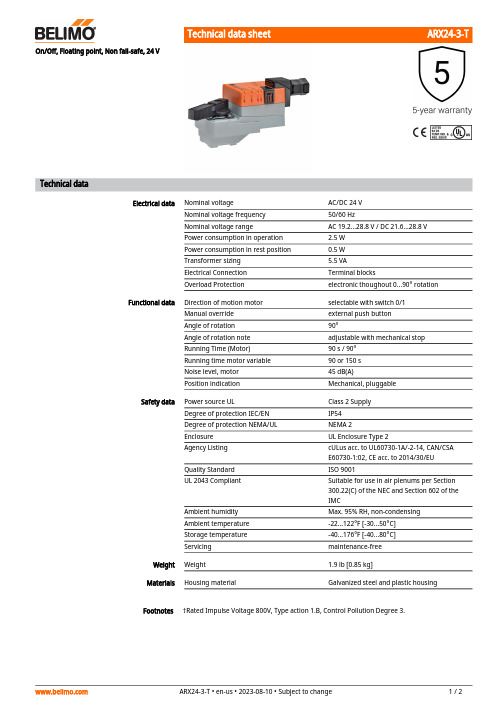
ARX24-3-TFootnotesOn/Off, Floating point, Non fail-safe, 24 VTechnical dataElectrical dataNominal voltageAC/DC 24 V Nominal voltage frequency 50/60 HzNominal voltage rangeAC 19.2...28.8 V / DC 21.6...28.8 V Power consumption in operation 2.5 W Power consumption in rest position 0.5 W Transformer sizing 5.5 VAElectrical Connection Terminal blocksOverload Protectionelectronic thoughout 0...90° rotation Functional dataDirection of motion motor selectable with switch 0/1Manual override external push button Angle of rotation 90°Angle of rotation note adjustable with mechanical stop Running Time (Motor)90 s / 90°Running time motor variable 90 or 150 s Noise level, motor 45 dB(A)Position indicationMechanical, pluggable Safety dataPower source ULClass 2 Supply Degree of protection IEC/EN IP54Degree of protection NEMA/UL NEMA 2Enclosure UL Enclosure Type 2Agency Listing cULus acc. to UL60730-1A/-2-14, CAN/CSA E60730-1:02, CE acc. to 2014/30/EU Quality Standard ISO 9001UL 2043 CompliantSuitable for use in air plenums per Section 300.22(C) of the NEC and Section 602 of the IMCAmbient humidity Max. 95% RH, non-condensing Ambient temperature -22...122°F [-30...50°C]Storage temperature -40...176°F [-40...80°C]Servicingmaintenance-free Weight Weight1.9 lb [0.85 kg]MaterialsHousing material Galvanized steel and plastic housing†Rated Impulse Voltage 800V, Type action 1.B, Control Pollution Degree 3.ARX24-3-T AccessoriesElectrical accessories Description TypeBattery backup system, for non-spring return models NSV24 USBattery, 12 V, 1.2 Ah (two required)NSV-BAT Electrical installationINSTALLATION NOTESProvide overload protection and disconnect as required.Actuators may be connected in parallel. Power consumption and input impedance must beobserved.Actuators may also be powered by DC 24 V.Actuators Hot wire must be connected to the control board common. Only connect common toneg. (-) leg of control circuits. Terminal models (-T) have no-feedback.Actuators are provided with a numbered screw terminal strip instead of a cable.Meets cULus requirements without the need of an electrical ground connection.Warning! Live electrical components!During installation, testing, servicing and troubleshooting of this product, it may be necessaryto work with live electrical components. Have a qualified licensed electrician or other individualwho has been properly trained in handling live electrical components perform these tasks.Failure to follow all electrical safety precautions when exposed to live electrical componentscould result in death or serious injury.Wiring diagramsOn/Off Floating PointFloating Point - Triac Source Floating Point - Triac Sink。
- 1、下载文档前请自行甄别文档内容的完整性,平台不提供额外的编辑、内容补充、找答案等附加服务。
- 2、"仅部分预览"的文档,不可在线预览部分如存在完整性等问题,可反馈申请退款(可完整预览的文档不适用该条件!)。
- 3、如文档侵犯您的权益,请联系客服反馈,我们会尽快为您处理(人工客服工作时间:9:00-18:30)。
s 11 11 11 11 11 11 11 11 11 10 10 10
Specifications
l Axial play
0.05 - 0.15 mm
l Max. sleeve bearing loads axial (dynamic) radial (5 mm from flange) Force for press fits (static) (static, shaft supported)
16 Mechanical time constant
ms 7
7
7
7
7
7
7
7
7
7
7
7
17 Rotor inertia
gcm2 3.92 4.15 4.2 4.18 4.08 4.07 4.01 4 3.95 3.88 3.74 3.79
18 Terminal inductance
mH 0.11 0.22 0.29 0.36 0.45 0.59 0.89 1.37 2.1 3.69 7.3 8.98
Short term operation The motor may be briefly overloaded (recurring).
10
20
30
M [mNm]
0.10
0.20
0.30
0.40
I [A] 220434 Motor with high resistance winding
220425 Motor with low resistance winding
10 Max. continuous current
mA 840 777 689 613 546 477 383 309 248 185 129 117
11 Max. continuous torque
mNm 8.19 11 11.1 11.1 10.9 10.9 10.8 10.8 10.8 10.7 10.4 10.5
Digital MR Encoder 32 CPT, 2 / 3 channels Details page 210 Digital MR Encoder 128 / 256 / 512 CPT, 2 / 3 channels Details page 211
l Options: Ball bearings in place of sleeve bearings, pigtails in place of terminals, without CLL.
1
2
3
4 I [A]
maxon Modular System
Planetary Gearhead Æ22 mm 0.5 - 2.0 Nm Details page 191
Spur Gearhead Æ38 mm 0.1 - 0.6 Nm Details page 200
Overview on page 17 - 21
8 Terminal resistance
Ohm 1.73 3.36 4.27 5.4 6.79 8.92 13.8 21.3 33 59.1 122 147
9 Max. permissible speed
rpm 6800 6800 6800 6800 6800 6800 6800 6800 6800 6800 6800 6800
140 maxon DC motor
Recommended Electronics:
LSC 30/2
page 231
MIP 10
245
Notes
ቤተ መጻሕፍቲ ባይዱ17
April 2003 edition / subject to change
14 Torque constant
mNm / A 9.75 14.1 16.1 18 20 22.9 28.3 35.1 43.4 57.5 80.9 89.7
15 Speed constant
rpm / V 979 675 593 529 478 417 338 272 220 166 118 106
12 Max. power output at nominal voltage
mW 5170 5990 4710 6630 5270 6270 5840 6720 6780 5450 4690 3880
13 Max. efficiency
% 88 88 88 88 88 88 88 88 88 88 87 87
rpm 5850 6050 5320 6330 5710 6230 6050 6500 6580 5950 5640 5080
4 Stall torque
mNm 33.9 37.9 33.9 40.1 35.3 38.5 36.9 39.6 39.5 35.1 31.9 29.2
5 Speed / torque gradient
rpm / mNm 174 161 158 158 162 162 165 165 167 170 178 175
6 No load current
mA 15 10
9
8
7
6
5
4
3
3
2
2
7 Starting current
mA 3470 2680 2110 2220 1770 1680 1310 1130 910 609 394 326
Motor Data (provisional)
1 Assigned power rating
W 6.5 6.5 6.5 6.5 6.5 6.5 6.5 6.5 6.5 6.5 6.5 6.5
2 Nominal voltage
Volt 6
9
9
12 12 15 18 24 30 36 48 48
3 No load speed
9
l Weight of motor
71 g
l Values listed in the table are nominal. For applicable tolerances see page 43. For additional details please use the maxon selection program on the enclosed CD-Rom.
45 N 440 N
l Radial play sleeve bearing
0.012 mm
l Radial play ball bearing
0.025 mm
l Ambient temperature range
-30 ... +85°C
l Max. rotor temperature
+85°C
l Number of commutator segments
RE-max 24 Æ24 mm, Precious Metal Brushes CLL, 6.5 Watt
maxon RE-max
Stock program Standard program Special program (on request!)
Order Number
M 1:1
220425 220426 220427 220428 220429 220430 220431 220432 220433 220434 220435 220437
19 Thermal resistance housing-ambient
K / W 17 17 17 17 17 17 17 17 17 17 17 17
20 Thermal resistance rotor-housing
K/W 7
7
7
7
7
7
7
7
7
7
7
7
21 Thermal time constant winding
l CLL = Capacitor Long Life
Operating Range n [rpm]
7000 6000 5000 4000 3000 2000 1000
6.5 Watt
Comments
Details on page 49
Recommended operating range
Continuous operation In observation of above listed thermal resistances (lines 19 and 20) the maximum permissible rotor temperature will be reached during continuous operation at 25°C ambient. = Thermal limit
1.0 N 2.8 N 80 N 440 N
l Max. ball bearing loads axial (dynamic) radial (5 mm from flange) Force for press fits (static) (static, shaft supported)
3.3 N 12.3 N