省电机技术手册
3MA22100 步进电机驱动器使用手册说明书

3MA22100(三相高压)细分步进驱动器使用手册Version1.0版权所有 不得翻印【使用前请仔细阅读本手册,以免损坏驱动器】宁波纳川自动化科技有限公司3MA22100步进电机驱动器使用说明 在使用本品前,请仔细阅读本使用说明书请妥善保管本说明书,以备日后参考本册外观图片仅供参考,请以实物为准安全注意事项请勿带电插拔连接线缆。
此产品非密封,请勿在内部混入镙丝、金属屑等导电性异物或可燃性异物,储存和使用时请注意防潮防湿。
驱动器为功率设备,尽量保持工作环境的散热通风。
在连上步进电机,调节好电流后使其连续工作半小时后观察步进电机是否在额定温度后方可进行后续使用,如果电机温度过高请联系制造商。
一、产品简介1.1 产品概述3MA22100是纳川科技最新推出的一款采用精密电流控制技术设计的高细分步进电机驱动器,适合驱动110-130型各种品牌的三相混合式步进电机。
由于采用了先进的抗噪声控制方法,能大幅度降低电机运转时的噪声和振动,使得步进电机运转时的噪声和平稳性趋近于伺服电机的水平。
和市场上的大多数其他细分驱动产品相比,步进电机和驱动器的发热量降幅达15-30%。
1.2 产品特点⏹高性能、低价格、超低噪声⏹电机和驱动器发热极低⏹供电电压AC110-250V⏹输出电流峰值可达8.3A(均值5.86A)⏹输入电信号TTL兼容(5V兼容)⏹静止时电流自动减半⏹可驱动三相混合式步进电机⏹高速光耦隔离信号输入,脉冲响应频率最高可达100KHz⏹抗高频干扰能力强⏹输出电流设定方便⏹有过压、欠压、过流、过热、相间短路保护功能1.2 应用领域适合各种大型自动化设备和仪器,例如:雕刻机、打标机、切割机、激光照排、绘图仪、数控机床、拿放装置等。
在用户期望低成本、小噪声、高速度的设备中效果特佳。
二、电气、机械和环境指标2.1 电气指标说明 3MA22100最小值 典型值 最大值 单位 输出电流 3.3(均值2.34)- 10(均值7.11) A 输入电源电压 110 180 250(含纹波)VAC 逻辑输入电流 7 10 16 mA 步进脉冲频率 0 - 40 KHZ 绝缘电阻500MΩ2.2 使用环境及参数冷却方式自然冷却使用环境场合 尽量避免粉尘、油雾及腐蚀性气体环境温度0℃-+50℃ 最高工作温度70℃湿度 40-90% RH9 (不能结露和有水珠)震动 5.9m/S2 Max 保存温度 -20℃-125℃ 重量约1500克2.3 机械安装图 单位:毫米2.4 加强散热方式(1)驱动器的可靠工作温度通常在65℃以内,电机的工作温度在80℃以内;(2)安装驱动器时请采用竖着侧面安装,形成较强的空气对流,必要时机内靠近驱动器出安装风扇,强制散热,保证驱动器在可靠的工作温度范围内工作。
电机使用说明书

偏航电机使用说明书本手册介绍了YEJ电磁制动三相异步电机的安装及使用方法,请仔细阅读并妥善保管,以使电机能够安全可靠有效的运行。
一.概述YEJ电磁制动三相异步电机用于驱动风力发电机偏航用齿轮箱,电机设计电压及频率为400/690V 50Hz,也可根据用户需要派生制造。
电机非驱动端安装有电磁制动器,用于电机制动,具体使用方法将在本说明书第六部分给出。
电机安装有加热带,工作电压及频率为230V 50Hz。
同时,电机还安装有温度传感器,保护温度为100℃。
二.工作条件1.海拔不超过1000m。
2.运行时环境温度:-40℃~+55℃。
3.相对湿度不超过100%。
4.空气允许含盐且含有细沙。
5.电源电压变化不超过额定值的±5%。
6.电源频率变化不超过额定值的±1%。
7.电机工作制为S3,最长连续运行时间不超过1小时。
三.运输与储存1.装卸及运输中不得拆箱,避免雨淋和剧烈震动。
2.如不立即使用,对电机的轴伸应涂防锈剂或临时性涂封材料,包装箱内需衬油毛毡纸及塑料膜,并加干燥剂。
3.存放地点应清洁,通风良好,不得有腐蚀性气体,环境温度最好不低于+3℃,避免雨淋。
四.安装和使用1.清除机体内的灰尘及轴伸的防锈层。
2.仔细检查各零部件装配是否良好,紧固件有无松动现象。
3.检查导电接触部分是否良好,如有锈斑应清除之。
4.用手轻转电机轴伸,查看转动是否灵活,并细听内部有无摩擦或碰装等杂声。
5.检查电机铭牌数据是否符合要求。
6.用500兆欧表测量绕组相间及对机壳绝缘电阻,若测得的电阻不低于表1即可使用。
低于上述值时,需将电机拆开进行干燥处理,一般情况下保持100~110℃温度烘8~10小时,干燥过程中应做好测量记录,开始每小时测一次,以后每半小时测一次,直到绝缘电阻稳定合格为止。
若无烘干装置,亦可采用通入短路电流的方法进行,此时转子应堵转,定子输入 1.5倍以下额定电流,保持发热温度70~75℃。
表17.检查接地装置是否妥善并接好地线,地线应用裸线。
维修电机技术手册
【标准名称】渔船电机修理技术要求 http://219.239.34.169/was40/detail?record=125&channelid=3849【标准号】SC/T 8042—94【标准文件】SC/T 8042—94渔船电机修理技术要求(渔船)1 主题内容与适用范围本标准规定了渔船交直流机的修理、安装、试验技术要求。
本标准适用于渔船及渔业辅助船交、直流电机的修理,其他电机可参照执行。
2 电机修理的一般规定2.1 电机修理前必须对电机做详尽的勘验,以便确定修理的范围及工程量。
2.2 检修电机必须认真填写电机修理记录单(见附录A和B)。
2.3 电机修理时使用的导电、导磁及绝缘材料的规格应类同于原电机制造材料、绝缘材料及油漆涂层应具有防霉性、化学稳定性、一定的机械强度和介电强度。
2.4 电机修理后应内外清洁无垢。
铭牌完整。
无油漆覆盖,字迹清晰,各零部件完好无缺。
螺栓、螺母应紧固无松动现象。
转子转动灵活、运转正常无异声。
轴伸径向无偏摆现象。
电刷应接触良好。
位置正确。
电机外壳及端盖应无影响机械强度的裂痕。
2.5 电机绕组更换或电机的出口引线更换后,必须在电机出线端套上永久性的标记。
电机接线应与端子标号一致,各端子的接触应紧密。
电机内部连线不得触及转动部分、转子和刷架的引出线应有完善的固定装置,并牢固无损。
3 电机主要零部件修理技术要求3.1 绕组的修理3.1.1 若确认绕组系外部因素引起的诸如部分灼焦、绝缘破坏、断路、短路,且又易于修理者,可局部包扎、烘潮喷漆。
但每台电机该类故障不得超过一处。
3.1.2 如电机绕组槽内部分绝缘破坏、断路、短路等以及槽外部分故障点每台超过一处,或虽为一处而不易检修者,一律拆除绕组重新绕制。
重新绕制的绕组,其绕线、绕组的绝缘嵌线、接头、烘潮和浸漆技术要求见本标准第5、6项。
3.1.3 对出线头绝缘损坏者,应拆去旧绝缘,换上相应绝缘等级的绝缘材料,烘潮喷漆。
3.1.4 若线圈端头或联接铜排之接合处连接不佳,应重新搪锡。
雷赛电机手册
雷赛电机使用手册一、简介雷赛电机是一种高效、稳定、可靠的电机产品,广泛应用于工业自动化领域。
本手册将为您介绍雷赛电机的使用方法、参数设置、维护保养以及故障排除等内容,帮助您更好地使用和维护电机。
二、设备安装1.安装前应仔细阅读本手册,了解电机的安装和使用要求。
2.根据电机的型号和规格,选择合适的安装位置和基础,确保电机安装稳固、可靠。
3.连接电机与电源时,应确保电源电压与电机额定电压相符,并采用适当的电缆和开关进行连接。
4.在安装过程中,应遵循电机的旋转方向要求,确保电机正常运转。
三、操作流程1.接通电源前,应检查电机是否正确安装,确保电机周围环境清洁、干燥、无杂物。
2.接通电源后,电机应正常运转,无异常声响和振动。
如有异常,应立即停机检查。
3.在操作过程中,应根据实际需求调整电机的转速和转向,以实现所需的运动方式和运动轨迹。
4.操作结束后,应关闭电机电源,并清理现场。
四、参数设置1.电机的主要参数包括电压、电流、转速、功率等,应根据实际需求进行设置。
2.在调整电机参数时,应遵循电机的工作特性和使用要求,避免超载或过载。
3.参数设置完成后,应保存并重启电机,以确保参数生效。
五、维护与保养1.定期检查电机的电源线、电缆和插头是否完好,如有破损应及时更换。
2.定期清理电机表面的灰尘和油污,保持电机清洁。
3.检查电机的轴承、齿轮等部件是否磨损严重,如有问题应及时更换。
4.在保养过程中,应遵循电机的拆装要求和注意事项,避免损坏电机或造成安全事故。
六、故障排除1.如电机出现异常声响、振动或过热等现象,应立即停机检查。
2.根据电机的故障现象,分析可能的原因并采取相应的措施进行排除。
如无法排除,应及时联系专业人员进行检查和维修。
3.在故障排除过程中,应注意安全操作,避免造成人员伤害或设备进一步损坏。
七、安全须知1.使用电机时应遵守相关安全规定和操作规程,确保人员和设备安全。
2.在操作过程中,应注意防止触电、机械伤害等安全事故的发生。
1000W 36V 锂电动机维修手册说明书

执行产品标准号:Q31/0117000520C001-2016目录第1章概述 (1)1.1原理 (1)1.2用途 (1)1.3特点 (1)第2章主要技术指标 (2)2.1技术指标 (2)2.2配件清单 (3)2.3仪器外观 (3)2.4仪器工作环境 (4)第3章仪器的基本操作 (6)3.1显示屏和按键 (6)3.2仪器安装 (7)3.3仪器的基本操作 (9)3.3.1调正空白 (9)3.3.2设置波长 (10)3.4试验前的准备 (11)第4章光度计模式 (11)4.1测试方法描述 (11)4.1.1透过率/吸光度模式 (12)4.1.2能量模式 (13)4.2打印实验报告 (13)第5章定量测量 (14)5.1创建标准曲线 (14)5.1.1根据标准样品 (14)5.1.1.1参数设置 (15)5.1.1.2测试标准样品 (16)5.1.1.3保存曲线方程文件 (21)5.1.1.4显示曲线方程/图谱 (22)5.1.2根据曲线方程系数 (22)5.1.2.1参数设置 (23)5.2编辑标准曲线 (24)5.3删除标准曲线 (25)5.4加载标准曲线 (26)5.5常用标准曲线 (27)5.6标准曲线测试 (28)第6章系统设置 (31)6.1时钟设置 (31)6.2暗电流测量 (32)6.3系统校正 (33)6.4波长修正 (34)6.5关于 (35)第7章电脑连接 (36)附录 A.故障排查 (37)附录 B.出错信息 (38)附录 C.更换钨灯 (40)附录 D.关键零件表 (41)第1章概述1.1原理分光光度法分析的原理是利用物质对不同波长光的选择吸收现象来进行物质的定性和定量分析,通过对吸收光谱的分析,判断物质的结构及化学组成。
本仪器是根据相对测量原理工作的,即选定某一溶剂(蒸馏水、空气或试样)作为参比溶液,并设定它的透射比(即透过率T)为100%,而被测试样的透射比是相对于该参比溶液而得到的。
江苏全兴电机有限公司质量手册
预防措施
45
9.1
检测设备运行检查
46
9.2
关键元器件和材料定期确认检验
47
9.3
产品例行检验和确认检验
48
9.4
认证证书和认证标志控制
49
9.5
产品包装、搬运和储存控制程序
50
9.6
认证产品的一致性
1 总则
1.1本手册的制定依据:
1.1.1 ISO9001:2008,本公司将跟踪ISO9001:2008的版本变化并及时更新。
4.1.5除以上过程外,公司对文件控制、质量记录两个具体过程也将编制程序文件进行有效控制。
4.1.6本公司质量管理体系以四大过程为基础,形成相关个具体的程序文件,并通过识别这些众多关联过程,确定这些过程的相互作用、规定过程有效运行的方法和准则、测量和分析过程的数据信息,达到确保顾客满意和实现质量管理体系的持续改进。
D.质量记录:质量活动实施的举证证明。
4.2.3文件控制
形成《文件控制程序》对下列与文件资料有关的活动进行规定:
A.使各个与质量有关场所能及时获得准确的文件的有效版本,并只使用有效版本。
B.所有文件,包括内部编制及来自外部,且无论其载体,只要与质量体系及产品质量有关,均应控制。
C.质量文件在其发布使用前,均应由指定的责任部门/人员进行审查及批准。其修改件由原审批部门/人员进行,如有更换,调阅原件档案以做参考。
形成《质量记录控制程序》对下列与质量记录有关的活动进行规定:
A.保存必要的记录,为产品满足要求且质量控制有效运行提供证据。质量记录包括来自于供应商的记录。
B.质量记录应按规定进行收集、整理、编目、立卷。各部门应合理保存质量记录,勿使其丢失和损坏。
电机控制技术手册

电机控制技术手册第一章:引言电机控制技术是现代工业中不可或缺的一部分。
它能够实现对电机系统的全面控制和管理,提高生产效率和产品质量。
本手册旨在介绍电机控制技术的基本原理和常见应用,帮助读者理解和掌握相关知识。
第二章:电机基础知识2.1 电机的工作原理电机是将电能转换为机械能的设备。
根据不同的原理和结构,电机可以分为直流电机、交流电机和步进电机等多种类型。
本节将详细介绍各种电机的工作原理和特点。
2.2 电机控制的基本原则电机控制的基本原则是根据实际需求对电机进行启动、停止、调速等操作。
常见的电机控制方法包括直接启动、星三角启动、变频调速等。
本节将详细介绍各种电机控制方法的原理和适用范围。
2.3 电机控制系统的组成电机控制系统由电源、控制器、传感器和执行器等组成。
每个组成部分都扮演着关键的角色,确保电机能够按照预定要求工作。
本节将逐一介绍各个组成部分的功能和作用。
第三章:电机控制技术的应用3.1 电动机控制系统电动机控制系统广泛应用于机械制造、能源、交通运输等领域。
本节将通过具体案例,介绍电动机控制系统在驱动各类机械设备中的应用和优势。
3.2 电机控制器的选型与调试电机控制器是电机控制系统中最重要的部分,其选择和调试对于系统的稳定性和性能至关重要。
本节将介绍如何根据实际需求选择合适的电机控制器,并对其进行调试和优化。
3.3 电机控制技术在智能制造中的应用随着工业智能化的发展,电机控制技术在智能制造中的应用越来越广泛。
本节将介绍电机控制技术在智能制造中的典型应用案例,包括自动化装配线、机器人等领域。
第四章:电机控制技术的发展趋势4.1 变频调速技术变频调速技术是当前电机控制技术的主流趋势之一。
本节将介绍变频调速技术的原理和应用优势,并展望其未来发展方向。
4.2 无感矢量控制技术无感矢量控制技术是电机控制技术领域的前沿技术。
本节将介绍无感矢量控制技术的原理和应用,并探讨其对电机控制技术的影响和未来发展方向。
UMK系列步进电机和驱动器包的技术参考手册说明书
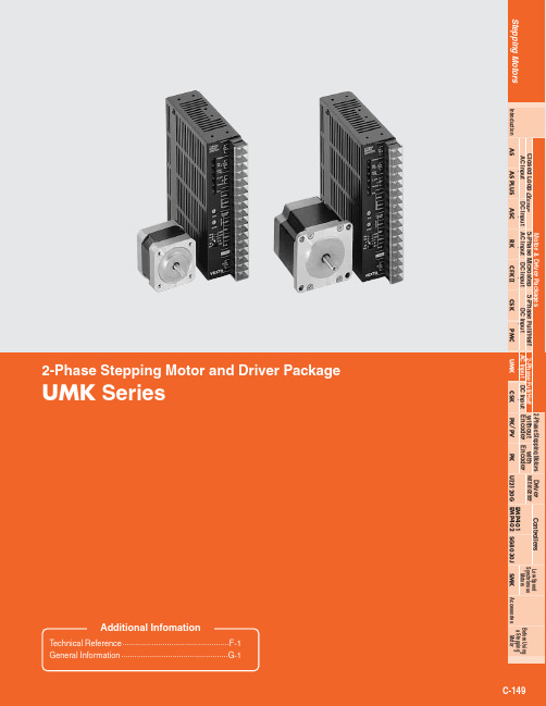
C-150Specifications/Characteristics C-1522-Phase Stepping Motor and Driver PackageUMK SeriesⅥFeaturesⅷHigh TorqueCombines a high torque PK motor with a dedicated driver.Maximum holding torque is as follows:UMK24Ⅺ: 22 oz-in (0.16 N·m)ϳ45 oz-in (0.32 N·m)UMK24ⅪM : 22 oz-in (0.16 N·m)ϳ45 oz-in (0.32 N·m)UMK26Ⅺ:55 oz-in (0.39 N·m)ϳ191 oz-in (1.35 N·m)UMK26ⅪM :55 oz-in (0.39 N·m)ϳ191 oz-in (1.35 N·m)ⅷLow Vibration and Low NoiseRaising the torque can increase vibration and audible noise.The UMK Series was designed to ensure low vibration and low noise. For a 2-phase stepping motor running at full step,rotation is achieved by continuous 1.8˚ steps. This is a type of motion that leads naturally to vibration. T o lower vibration and noise, it is important to make rotation as smooth aspossible.The UMK Series provides high torque and low vibration.ⅷHigh-Resolution TypeThe UMK Series also includes high resolution models forwhich the basic step angle (1.8˚/step) is cut in half to 0.9˚/step (for full steps).The resolution is doubled from the 200 steps per rotation for the standard models to 400 steps per rotation. Consequently,the high-resolution model can be half-stepped to obtain 800steps per rotation.C-151Dimensions C-155Common Specifications C-154Connection and Operation C-156Motor and Driver Combinations C-160AA M 662UMK Programmable Controller MotorDriverFlexible CouplingsEMP400 Controller (Sold separately)(➝Page C-254)Mounting Brackets (Accessories)(➝Page C-291)I/O Cable with Terminal Block (Accessories)(➝Page C-264)Clean Dampers (Accessories)(Not supplied)ⅥProduct Number CodeBlank: Standard Type M :High-Resolution TypeMotor Case Length2-phaseUMK SeriesMotor Frame Size 4: 1.65 in. sq. (42 mm sq.)6:2.22 in. sq. (56.4 mm sq.)U.S.A. VersionShaft Type A : Single ShaftB : Double ShaftC-152System Configuration C-151Features C-150Specifications/Characteristics C-152How to Read Specifications Table ➝Page C-9ⅥSpeed — Torque Characteristics How to Read Speed-Torque Characteristics ➝Page C-10UMK243BAUMK264BAUMK244BAUMK266BAUMK245BAUMK268BAPulse Speed [kHz]0(0)15(30)10(20)5(10)Speed [r/min]024860.40.60.81.01.21.41.60.2T o r q u e [N ·m ]C u r r e n t [A ]T o r q u e [o z -i n ]Power Input: 115 VAC Current: 2 A/Phase (2 Phases ON)2מ72)Full Step (Half Step)Pulse Speed [kHz]0(0)15(30)10(20)5(10)Speed [r/min]0012430.20.30.40.1T o r q u e [N ·m ]C u r r e n t [A ]T o r q u e [o z -i n ]Power Input: 115 VAC Current: 1.2 A/Phase (2 Phases ON) 2מ72)Full Step (Half Step)Pulse Speed [kHz]0(0)15(30)10(20)5(10)Speed [r/min]02460.40.60.81.01.20.2T o r q u e [N ·m ]C u r r e n t [A ]T o r q u e [o z -i n ]Power Input: 115 VAC Current: 2 A/Phase (2 Phases ON)2מ72)Full Step (Half Step)Pulse Speed [kHz]0(0)15(30)10(20)5(10)Speed [r/min]Full Step (Half Step)1230.100.150.200.250.300.350.05T o r q u e [N ·m ]C u r r e n t [A ]T o r q u e [o z -i n ]Power Input: 115 VAC Current: 1.2 A/Phase (2 Phases ON) 2מ72)Pulse Speed [kHz]0(0)15(30)10(20)5(10)Speed [r/min]Full Step (Half Step)2460.20.30.40.50.1T o r q u e [N ·m ]C u r r e n t [A ]T o r q u e [o z -i n ]Power Input: 115 VAC Current: 2 A/Phase (2 Phases ON)2מ72)Pulse Speed [kHz]0(0)15(30)10(20)5(10)Full Step (Half Step)Speed [r/min]01230.100.150.200.250.05T o r q u e [N ·m ]C u r r e n t [A ]T o r q u e [o z -i n ]Power Input: 115 VAC Current: 0.95 A/Phase (2 Phases ON) 2מ72)Standard Type Motor Frame Size: Ⅺ 1.65 in. (Ⅺ 42 mm), Ⅺ 2.22 in. (Ⅺ 56.4 mm)Note:The pulse input circuit responds up to approximately 20 kHz with a pluse duty of 50 %Note:The pulse input circuit responds up to approximately 20 kHz with a pluse duty of 50 %How to Read Specifications Table➝Page C-9ⅥSpeed — Torque Characteristics How to Read Speed-Torque Characteristics➝Page C-10UMK243MBA UMK264MBAUMK244MBA UMK266MBAUMK245MBA UMK268MBAPulse Speed [kHz](0)30(60)20(40)10(20)Speed [r/min]12430.40.60.81.01.21.41.60.2Torque[N·m]Current[A]Torque[oz-in]Power Input: 115 VAC Current: 2 A/Phase (2 Phases ON)2מ72)Full Step(Half Step)Pulse Speed [kHz](0)30(60)20(40)10(20)Speed [r/min]120.20.30.40.1Torque[N·m]Current[A]Torque[oz-in]Power Input: 115 VAC Current: 1.2 A/Phase (2 Phases ON)2מ72)Full Step(Half Step)Pulse Speed [kHz](0)30(60)20(40)10(20)Speed [r/min]1230.40.60.81.01.20.2Torque[N·m]Current[A]Torque[oz-in]Power Input: 115 VAC Current: 2 A/Phase (2 Phases ON)2מ72)Full Step(Half Step)Pulse Speed [kHz](0)30(60)20(40)10(20)Speed [r/min]Full Step(Half Step)0.511.50.100.150.200.250.300.350.05Torque[N·m]Current[A]Torque[oz-in]Power Input: 115 VAC Current: 1.2 A/Phase (2 Phases ON)2מ72)Pulse Speed [kHz](0)30(60)20(40)10(20)Speed [r/min]Full Step(Half Step)1230.20.30.40.50.1Torque[N·m]Current[A]Torque[oz-in]Power Input: 115 VAC Current: 2 A/Phase (2 Phases ON)2מ72)Pulse Speed [kHz](0)30(60)20(40)10(20)Full Step(Half Step)Speed [r/min]0.511.50.100.150.200.250.05Torque[N·m]Current[A]Torque[oz-in]Power Input: 115 VAC Current: 0.95 A/Phase (2 Phases ON)2מ72)High-Resolution Type Motor Frame Size: Ⅺ 1.65 in. (Ⅺ 42 mm), Ⅺ 2.22 in. (Ⅺ 56.4 mm)C-153 Dimensions C-155Common Specifications C-154Connection and Operation C-156Motor and Driver Combinations C-160C-154System Configuration C-151Features C-150Specifications/Characteristics C-152ⅥCommon SpecificationsⅥGeneral SpecificationsC-155Dimensions C-155Common Specifications C-154Connection and Operation C-156Motor and Driver Combinations C-160Unit = Upper values: lb./Lower values: NⅥDimensions Scale 1/4, Unit = inch (mm)ⅷStandard and High-Resolution Type Motors z Motor Frame Size: Ⅺ1.65 in. (Ⅺ42 mm)✽The length of machining on double shaft model is 0.591Ϯ0.010(15Ϯ0.25).x Motor Frame Size: Ⅺ2.22 in. (Ⅺ56.4 mm)●These dimensions are for double shaft models. For single shaft models, ignore the shaded areas.C-156System Configuration C-151Features C-150Specifications/Characteristics C-152ⅷDriverc UDK2109A, UDK2112A, UDK2120AWeight: 1 lb. (0.47 kg) d B087ⅷMounting Bracket A (2 pieces, included)ⅥConnection and OperationzxcPower Input TerminalszSignal Monitor Displayx Current Adjustment Switchesc Function Select SwitchesC-157Dimensions C-155Connection and Operation C-156Motor and Driver Combinations C-160ⅥConnection DiagramsControllerDriverࡗPower SupplyCan be used with a single-phase 115 VAC, 60 Hz or 100 VAC, 50/60 Hz power supply. Use a power supply that can supply sufficient input current. If power supply capacity is insufficient, a decrease in motor output can cause the following malfunctions:• Motor does not rotate properly at high-speed (insufficient torque).• Slow motor startup and stopping.Notes :• Keep the voltage Vo between 5 VDC and 24 VDC. When it is equal to 5VDC, the external resistance R 1is not necessary. When it is above 5 VDC,connect R 1to keep the current between 10 mA and 20 mA, and connect R 2to keep the current below 10 mA.• Use twisted-pair wire of AWG 24 or thicker and 6.6 feet (2 m) or less in length for the signal line.• Note that as the length of the pulse signal line increases, the maximum transmission frequency decrease.(➝Technical Reference Page F-36)• Use AWG 20 or thicker for motor lines (when extended) and power supply lines, and use AWG 18 or thicker for the wire for the grouding line.• Use spot grounding for the grounding of the driver and external controller.• Signal lines should be kept at least 3.9 inches (10 cm) away from power lines (power supply lines and motor lines). Do not bind the signal line and power line together.• Use open collector transistors (sink type) for the signal output sections of the controller.ࡗTerminalsCrimp terminals are not provided with the package.C-158System Configuration C-151Features C-150Specifications/Characteristics C-152ⅥDescription of Input/Output SignalsPulse (CW) Input and Rotation Direction (CCW)Input SignalThe characters indicate signals under the 1-pulse input mode, while the characters in parentheses indicate signals under the 2-pulse input mode.Note:• When Vo is equal to 5 VDC, the external resistance (R) is not necessary. When Vo is above 5 VDC, connect the external resistance (R) and keep the input current between 10 mA and 20 mA.1-Pulse Input Mode Pulse Signal"Pulse" signal is input to the pulse signal terminal. When the photocoupler state changes from "ON" to "OFF", the motor rotates one step. The direction of rotation is determined by the following rotation direction signal.Rotation Direction SignalThe "Rotation Direction" signal is input to the rotationdirection signal input terminal. A "photocoupler ON" signal input commands a clockwise direction rotation. A "photocoupler OFF" signal input commands a counterclockwise direction rotation.2-Pulse Input ModeCW and CCW refer to clockwise and counterclockwise direction respectively, from a reference point of facing the motor output shaft.CW Pulse SignalWhen the photocoupler state changes from "ON" to "OFF",the motor rotates one step in the clockwise direction.CCW Pulse SignalWhen the photocoupler is state changes from "ON" to "OFF", the motor rotates one step in the counterclockwise direction.ࡗPulse Waveform Characteristics(Photocoupler state corresponding to the input pulse)✽The shaded area indicates when the photocoupler is ON. The motor moves when the photocoupler state changes from ON to OFF as indicated by theࡗPulse Signal Characteristics• The pulse voltage is 4.5 to 5V in the "photocoupler ON"state, and 0 to 1V in the "photocoupler OFF" state.• Input pulse signals should have a pulse width over 2µs,pulse rise/fall time below 1µs and a pulse duty below 50%.• Keep the pulse signal at "photocoupler OFF" when no pulse is being input.• The minimum interval time when changing rotation direction is 50 s.This value varies greatly depending on the motor type,pulse frequency and load inertia. It may be necessary to increase this time interval.•In 1-pulse input mode, leave the pulse signal at rest ("photocoupler OFF") when changing rotation directions.All Windings Off (A.W.OFF) Input Signal Note:• When Vo is equal to 5 VDC, the external resistance (R) is not necessary. When Vo is above 5 VDC, connect the external resistance (R) and keep the input current between 10 mA and 20 mA.When the "All Windings Off " signal is in the "photocoupler ON" state, the current to the motor is cut off and motor torque is reduced to zero. The motor output shaft can then be rotated freely by hand.When the "All Windings Off " signal is in the "photocoupler OFF" state, the motor holding torque is proportional to the current set by the current adjustment rotary switches. During motor operation be sure to keep the signal in the "photocoupler OFF" state.This signal is used when moving the motor by external force or manual home position is desired. If this function is not needed, it is not necessary to connect this terminal.Switching the "All Windings Off " signal from "photocoupler ON" to "photocoupler OFF" does not alter the excitation sequence.When the motor shaft is manually adjusted with the "All Windings Off " signal input, the shaft will shift up to Ϯ3.6˚from the position set after the "All Windings Off " signal is released.C-159Dimensions C-155Common Specifications C-154Connection and Operation C-156Motor and Driver Combinations C-160Excitation Timing Signal (TIM.) Output SignalNote:• Keep the voltage between 5 VDC and 24 VDC.Keep the current below 10 mA.If the current exceeds 10 mA, connect external resistance (R).The "Excitation Timing" signal is output to indicate when the motor excitation (current flowing through the winding) is in the initial stage (step "0" at power up).The "Excitation Timing" signal can be used to increase the accuracy of home position detection by setting themechanical home position of your equipment (for example, a photo-sensor) to coincide with the excitation sequence initial stage (step "0").The motor excitation stage changes simultaneously with pulse input, and returns to the initial stage for each 7.2˚rotation of the motor output shaft.When the power is turned ON, the excitation sequence is reset to step "0".The TIM. LED lights when the "Excitation Timing" signal is output. While the motor is rotating, the LED will turn ON and OFF at a high speed and will appear to be continuously lit.The "Excitation Timing" signal is output simultaneously with a pulse input each time the excitation sequence returns to step "0".The excitation sequence will complete one cycle for every 7.2˚ rotation of the motor output shaft.Full Step (the switch is set to F position): Signal is output once every 4 pulses.Half Step (the switch is set to H position): Signal is output once every 8 pulses.Timing chart at full stepNotes:●When the power is turned ON, the excitation sequence is reset to STEP 0and the LED lights up.●The LED flashes quickly while the motor runs, appearing continuously lit.✽When connected as shown in the example connection, the signal will be “photocoupler ON” at step “0” .Overheat (O.HEAT) Output SignalNote:• Keep the voltage between 5 VDC and 24 VDC.Keep the current below 10 mA.If the current exceeds 10 mA, connect external resistance (R).The "Overheat" signal is output to protect the driver against burnout when its internal temperature rises abnormally high due to high ambient temperature. The O.HEA T lamp on the front panel lights up when output.When used as shown in the sample connection with the overheat output logic switch set to NO, the signal becomes "photocoupler ON". (Switch to NC to set to the "photocoupler OFF".)If the A.C.O. (Automatic Current OFF) function is set, the output current to the motor drops to zero and the motor stops automatically.When the "Overheat" signal is output, check the operating conditions (ambient temperature, driver settings) and cool the driver.The "Overheat" signal automatically releases as the internal temperature of the driver drops. The overheat signal turns "photocoupler OFF" and the O.HEA T indicator turns off.C-160Enter A (single shaft) or B (double shaft) in the box (Ⅺ) within the model numbers.ⅥTiming Chart✽1Switching time to change CW, CCW pulse (2-pulse input mode)Switching time to change direction (1-pulse input mode) 50 s is shown as a response time of circuit. Motor needs a time more than that.✽2Depends on load inertia, load torque, start frequency.✽3Never input a step pulse signal immediately after switching the "All Winding Off" signal to the photocoupler off state. The motor may not start.✽4Wait 5 seconds before cycling the power on.MotorPower InputCW Pulse Input Signal CCW Pulse Input Signal Pulse Input Signal All Windings OFF Input Signal Rotation Direction Input Signal 1-Pulse Input Mode2-Pulse Input ModeCWON ON ONON ONON。
威灵电机产品手册说明书

本手册印制于2018年12月,欲了解最新产品技术信息,请访问Welling官方网站:This manual was printed in Dec. 2018. For technical details about the latest products, please visit Welling website: PRODUCT 2019 MANUAL威灵电机产品手册Welling Shanghai R&D Center (CNAL Test Verification Center) is committed to the study on the motors with high energy efficiency, low noise and stable performance.Welling上海研发中心(CNAL测试验证中心)致力于高能效、低噪音、性能稳定电机方向的研究。
Shunde, Guangdong广东顺德Changzhou, Jiangsu江苏常州上海Shanghai安徽芜湖Wuhu, Anhui 江苏淮安Huai’an, Jiangsu 四大电机制造基地六大工厂,2018冷年产销电机1.7亿台。
其中,空调电机、洗衣机电机占市场份额分别超过30%和16%。
Four major motor manufacturing bases and six major factories, Welling achieved production and sales of 170million motors in 2018 refrigeration year , among which Air-conditioner motors and washing machine motors their market shares are 30% and 16% higher, respectively.我们的体系MarketWelling电机产品广泛应用于家用电器领域、清洁设备、泵类产品和工业自动化等领域,如各类空调、洗衣机、洗碗机、吸尘器、净水器等;Welling motor products are widely used in the fields of household appliances, cleaning equipment, pump products and industrial automation, such as air conditioners, washing machines, dishwashers, vacuum cleaners, water purifiers, etc.我们的产品应用ProductWelling于1992年创建于广东顺德,是一家专业化研发、生产、销售电机及其驱动系统的精密制造企业,为国内外客户提供系统的电机技术解决方案;Welling was founded in 1992, specializing in R&D and manufacturing of motors and their driving systems, itsproducts are widely used in the fields of household appliances, cleaning equipment, pump products and industrial automation.我们的企业Company6个现代化工厂,年产能2.2亿台6 modern factories, with an annual production capacity of 220 million unitsCOMPANYPROFILE公司简介2001年佛山市威灵电子电器公司注册成立In 2001,Welling Electronics Co.,Ltd. in Foshan was registered to be founded 2011年威灵电机技术(上海)有限公司成立2014年入选中国外贸出口先导样本企业In 2014,Selected as a China's ELI(export leading index)sample enterpriseDEVELOPMENT MILE发展里程1998年INNOVATIVETECHNOLOGIES创新科技Welling一直致力于高能效、低噪音、性能可靠的电机研究,为客户提供系统的电机技术解决方案。
电机的技术手册

电机的技术手册电机的技术手册1:概述1.1 电机的定义及作用1.2 电机的分类1.2.1 直流电机1.2.2 交流电机1.2.3 步进电机1.3 电机的基本原理1.4 电机的应用领域2:直流电机2.1 直流电机的结构和工作原理2.2 直流电机的特点和性能参数2.2.1 额定转速和额定转矩2.2.2 转速调节方式2.2.3 效率和功率因数2.3 直流电机的控制方法2.3.1 手动控制2.3.2 自动控制2.4 直流电机的维护与保养2.4.1 清洁与润滑2.4.2 定期检查与维修2.4.3 故障排除与维修常见问题3:交流电机3.1 交流电机的结构和工作原理3.2 交流电机的分类3.2.1 感应电动机3.2.2 永磁同步电动机3.2.3 刷碳电动机3.3 交流电机的特点和性能参数3.3.1 转速与转矩关系3.3.2 功率因数和效率3.4 交流电机的控制方法3.4.1 转速控制3.4.2 转向控制3.5 交流电机的维护与保养3.5.1 清洁与润滑3.5.2 定期检查与维修3.5.3 故障排除与维修常见问题4:步进电机4.1 步进电机的结构和工作原理4.2 步进电机的分类4.2.1 增量式步进电机4.2.2 绝对式步进电机4.3 步进电机的特点和性能参数4.4 步进电机的控制方法4.4.1 开环控制4.4.2 闭环控制4.5 步进电机的维护与保养4.5.1 清洁和润滑4.5.2 定期检查与维修4.5.3 故障排除与维修常见问题5:附件附件1:电机连接图附件2:电机技术参数表格附件3:电机维修保养记录表6:法律名词及注释1:电机:根据国家电力法,电机是将电能转换为机械能的设备。
7:全文结束。
湘潭电机使用维护说明书
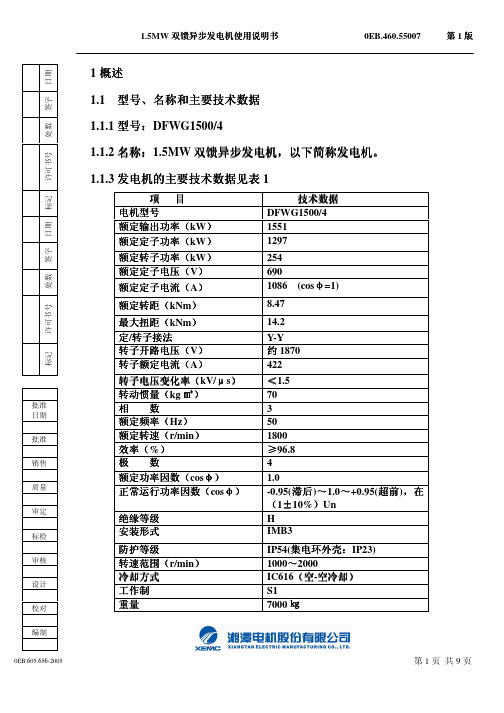
第3页 共9页
1.5MW 双馈异步发电机使用说明书
0EB.460.55007
第1版
4.2 安装
4.2.1 安装前的检查
a)检查电气连接是否符合接线图,连接是否可靠
b)用 1000V 兆欧表测量发电机定子绕组对机壳的冷态绝缘电阻不应低
于 50MΩ;
c)检查发电机转子转动不应有卡死现象和异常响声; d)检查发电机紧固件是否松动;
两轴承温度应不超过 95℃(温度计法); b)应该及时填写发电机的运行记录; c)环境空气温度低于 0℃时, 要对电机进行加热,保证轴承油脂不发
硬不至于影响电机的正常运行; d)发电机在空载及刚带负荷运行时,电机轴承可能有异响,但加负载
运行一段时间后,异响消失,此情况是由于轴承运行温度升高,轴 承油膜建立,滚珠润滑均匀,属于正常现象,不影响电机使用。 4.4 拆卸和装配 4.4.1 为确保人身设备安全,严禁自行拆装本发电机,必须由经培训的相关 专业人员进行。 4.4.2 为方便装配和不破坏整个电机的平衡,拆卸后,各零、部件间的配合处应 作相应的定位标记,重装时,这些标记应相互对准。 4.4.3 滑环和轴承拆卸和装配时,分别需要特制的拉具、压具拉、压其内圈,
6.4 轴承的维护、保养及更换 6.4.1 电机已由制造厂加注了正确牌号和正确数量的润滑脂,因此建议累计
运行 1000~1500h 后加注一次润滑脂。
6.4.2 加润滑脂时,如原有润滑脂未变质、弄脏,就不必清除,以避免轴承盖等
不必要的拆动;当必须拆开轴承盖时,须十分小心,不要弄脏润滑脂, 不要让
灰尘、潮气进入轴承室和润滑脂内。
d. 转子风叶碰壳
校正风叶
3
电机过热
绿色制造高效电机制造指南说明书

序号标准名称主要起草单位参与单位
1
T/ZZB G001-2022
《绿色制造高效电机
制造指南》
浙江金龙电机股份有限公司
浙江省标准化研究院、浙江省电机标准
化技术委员会、浙江大学电气工程学院、
浙江省机电设计研究院、浙江省电机动
力学会、台州市路桥区电机行业协会、
浙江省台州路桥机电产业创新服务综合
体、台州市标准化研究院、台州市金宇
机电有限公司、葛氏控股股份有限公司、
浙江盘毂动力科技有限公司、舟山东海
电机实业有限公司、力速电机有限公司、
恒速控股有限公司、浙江德东电机股份
有限公司、汇龙电机有限公司、冠龙电
机有限公司、浙江九洲新能源科技有限
公司、浙江奇志电机股份有限公司、浙
江翱隆电机科技有限公司、浙江沪特电
机有限公司、浙江巨奥电机制造有限公
司、方力控股股份有限公司、浙江大奕
电机股份有限公司、沪源电机有限公司、
浙江佳乐科仪股份有限公司、台州市路
桥区产品质量检验所。
Parker Hannifin 电机控制器技术手册说明书
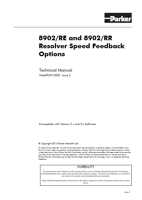
8902/RE and 8902/RR Resolver Speed Feedback OptionsTechnical ManualHA469251U002 Issue 2Compatible with Version 2.x and 3.x SoftwareCopyright 2014 Parker Hannifin Ltd.All rights strictly reserved. No part of this document may be stored in a retrieval system, or transmitted in any form or by any means to persons not employed by a Parker Hannifin Manufacturing Limited company without written permission from Parker Hannifin Manufacturing Ltd. Although every effort has been taken to ensure the accuracy of this document it may be necessary, without notice, to make amendments or correct omissions. Parker Hannifin Manufacturing Limited cannot accept responsibility for damage, injury, or expenses resulting therefrom.WARRANTYThe general terms and conditions of sale of goods and/or services of Parker Hannifin Europe Sarl, Luxembourg, Switzerland Branch, Etoy, apply to this product unless otherwise agreed. The terms and conditions are available onour website /termsandconditions/switzerland.Parker Hannifin Manufacturing Limited reserves the right to change the content and product specification withoutnotice.Cont.1WARNING!During commissioning, remove the fuses (or trip the circuit breaker) on your 3-phase supply.Make sure the power is OFF, and that it cannot be switched on accidentally whilst youare working.REFER TO YOUR MAIN PRODUCT MANUAL FOR SPECIFIC SAFETYINFORMATION ABOUT THE DEVICE YOU ARE CONTROLLING IMPORTANT:Please read this information BEFORE installing the equipment.Intended UsersThis manual is to be made available to all persons who are required to install, configure orservice equipment described herein, or any other associated operation.The information given is intended to highlight safety issues, EMC considerations, and to enablethe user to obtain maximum benefit from the equipment.Application AreaThe equipment described is intended for industrial motor speed control utilising AC induction orAC synchronous machines.PersonnelInstallation, operation and maintenance of the equipment should be carried out by qualifiedpersonnel. A qualified person is someone who is technically competent and familiar with allsafety information and established safety practices; with the installation process, operation andmaintenance of this equipment; and with all the hazards involved.SafetyAll control and signal terminals are SELV, i.e. protected by double insulation.EMCIn a domestic environment this product may cause radio interference in which case the user maybe required to take adequate counter-measures.This equipment contains electrostatic discharge (ESD) sensitive parts. Observe static controlprecautions when handling, installing and servicing this product.Cont.2Cont.3CAUTION!At any time, there may be a loss of motor control and separate/independent application measures should be taken to ensure that such loss of motor control cannot present a safety hazard.RISK ASSESSMENTUnder fault conditions, power loss or unintended operating conditions, the drive may not operate as intended. In particular:• Stored energy might not discharge to safe levels as quickly as suggested, and can still be present even though the drive appears to be switched off• The motor's direction of rotation might not be controlled• The motor speed might not be controlled • The motor might be energisedA drive is a component within a drive system that may influence its operation or effects under a fault condition. Consideration must be given to: • Stored energy• Supply disconnects• Sequencing logic• Unintended operationContentsContents PageCont.41 Description (1)•Features (1)•Part Number (1)•Used On (1)•Specifications – Resolver Interface (8902/RE and 8902/RR) (2)•Specifications – Resolver Interface (8902/RE and 8902/RR) (2)•Specifications – Emulated Encoder (8902/RR only) (2)Recommended Spare Parts (2)Installation (3)Fitting the Option (3)Wiring the System (4)•D-Type Connections (4)Approved Resolvers (6)Encoder Emulation (7)Initial Set-up (8)Configuring the 890 Drive (8)•RESOLVER Function Block (8)Motor Phasing (10)18902/RE Resolver Speed Feedback OptionDescriptionThe 8902/RE and 8902/RR Resolver Speed Feedback Options allow resolvers to be connected directly to the motor controller to provide highly accurate speed feedback measurement. In addition, the 8902/RR provides an emulated pulse encoder output.FeaturesThe Option has the following features:• Contains two differential inputs on channels Sin and Cos • Contains a carrier output signal to power the Resolver • 8902/RR contains three differential outputs, emulating a pulse encoder.Part NumberThe part number for the Resolver Speed Feedback Option is :8902/RE/00/008902/RE/00/FF (indicates a factory-fitted Option)8902/RR/00/008902/RR/00/FF (indicates a factory-fitted Option)Used OnThis Option can be used on 890 drives with the following Product Codes:890SD/.. 890SD Standalone Drive 890CD/.. 890CD Common Bus Drive890P…..Refer to the 890 Engineering Reference Manual, Appendix E for Product Code details.Note: 8902/RE may be supplied as Style1 orStyle 2 (refer Figure 1 and 2).Figure 1 - Style 1: 8902/RE Resolver SpeedFeedback OptionFigure 2 –Style 2: 8902/RR Resolver Speed Feedback Option28902/RE Resolver Speed Feedback OptionSpecifications – Resolver Interface (8902/RE and 8902/RR)Maximum Speed8902/RE:Up to 50,000RPM (with 2 pole resolver ) 8902/RR:Up to 30,000RPM (with 2 pole resolver )Carrier Output Signal 7Vrms, 8kHz Maximum Carrier Supply 70mA rms Maximum Input Voltage ±12V peak Accuracy < 5 minutesResolution Equivalent to 16 bits per electrical revolution of resolverInputsDifferential inputs, Zin ~2 k Ω Maximum input voltage : 12VpeakIsolationNoneSpecifications – Emulated Encoder (8902/RR only)Signal amplitude Compatible with RS422 and RS485 Outputs3 Differential pairs Signal nomenclatureA andB quadrature Z index pulse Number of lines per revolution 1024Isolation Outputs are isolated from drive electronicsRecommended Spare PartsWe recommend that you keep one Option as a spare to reduce down-time.38902/RE Resolver Speed Feedback OptionFigure 3 Rear ofControl Board ABBAInstallationFitting the OptionIf the Option is not factory-fitted, follow the proceduregiven below.WARNING!Disconnect all sources of power beforeattempting installation.CautionThis Option contains ESD (Electrostatic Discharge)sensitive parts. Observe static control precautions whenhandling, installing and servicing this Option.1.Undo the two screws securing Option A and Option Bto the front of the drive. If Options are not fitted,completely remove the blank covers for the Option Aand Option B slots.2.Undo the screws (A) located in the top and bottomhandles of the control board. Gently pull on the handlesto withdraw the board from the drive, supporting anyattached option boards. Note that the boards are slidingin top and bottom slots.3.Remove any other Options that are fitted to the controlboard.4.Offer up the Resolver Option through the "OPTION F"cut-out as shown opposite.5.Fit the two locating pegs of the large connector on therear edge of the option board into the locating holes onthe control board, as shown below.6.Fit the two screws and crinkle washers (C) at the rear edge of the Option.DO NOT OVERTIGHTEN.Tightening torque : 0.2Nm (28 oz-in).7.Secure with the two screws (B) to the front of the controlboard.The front panel screws (B) are self-tapping and can bequite hard to turn. This turning torque must not betransferred through the option board to the control boardconnector. To avoid this hold the option board with onehand, while tightening the front panel screws with theother. DO NOT hold the control board while tighteningthese screws.8.Refit any other Options that were removed from the controlboard.9.Replace the control board (with attached Options) into thedrive.10.Tighten the Option A and Option B screws; or importantly,fit the blank covers and secure with the screws.48902/RE Resolver Speed Feedback OptionWiring the SystemWARNING!Disconnect all sources of power before attempting installation.CautionThis Option contains ESD (Electrostatic Discharge) sensitive parts. Observe static controlprecautions when handling, installing and servicing this Option.D-Type ConnectionsNote: For correct operation, carrier, sine and cosine must be connected as specified. Poorperformance/motor behaviour may occur if these signals are left unconnected or are connected incorrectly.Take special care wiring the resolvers to the Option due to the low level of the signals. Ideally use twisted-pair, screened cable with an overall screen and a screen over each individual pair. It may be possible to use a cable with just a screen over each individual pair. The signal pairs should have characteristic impedance of 120Ω. To ensure compliance with the EMC Directive the overall cable screen should be connected to the connector body and to the cable clamp. Connect overall screen and individual screens together, on each side of the cable. Use the resolver manufacturer's recommended cable.1234567891011121314151 Sin+ input23 Cos+ input4 not connected5 not connected6 not connected78 + carrier input, reference voltage9 Sin- input10 11 Cos- input 12 not connected 13 not connected 14 not connected15 - carrier input, reference voltagenot connected not connectednot connected OPTION BOARD+ -+ -SinCos +-+-RESOLVERSin Cos +-+-Power+-BracketX30X30 Terminal:Carrier Input+-Figure 4 Wiring Diagram 8902/RE58902/RE Resolver Speed Feedback Option134567891011121314151 Sin+ input23 Cos+ input4 Index Z+ output5 Quadrature A+ output6 Quadrature B+ output78 + carrier input, reference voltage9 Sin- input 10 11 Cos- input12 Index Z- output13 Quadrature A- output 14 Quadrature B- output15 - carrier input, reference voltagenot connected not connectednot connected OPTION BOARD+ -+ -Sin Cos +-+-RESOLVERSin Cos +-+-Power+-BracketX36X36 T erminal:Carrier Input+-2+-+-+-Q u a d r a t u r e AQ u a d r a t u r e B I n d e x ZT o encoder inputFigure 5 Wiring Diagram 8902/RR68902/RE Resolver Speed Feedback Option Resolver DiagramCOSINE input : Vcos = V(S1-S3) = V(R1-R2) x TR x cosθSINE input : Vsin = V(S2-S4) = V(R1-R2) x TR x sinθWith : Vin = V(R1-R2) : carrier signal ( reference voltage )TR = transformation ratioϕ = positionApproved ResolversParker SSD Drives approve the following Resolvers for use with the 8902/RE Speed FeedbackOption.Tamagawa TS2610N71E64Tamagawa TS2620N701E11Tamagawa TS2620N861E11Tamagawa TS2640N821E64Encoder EmulationEncoder emulation creates three differential pairs, A, B and Z. These emulate a 1024 lineencoder rotating at the same speed and direction as the resolver. Clockwise rotation of theencoder shaft normally causes channel A to lead channel B, but this could reverse depending onthe resolver wiring.Initial Set-upConfiguring the 890 DriveNote:The DSE 890 Configuration Tool is Parker SSD Drives’ Windows-based blockprogramming software and is supplied with each drive.Use the DSE 890 Configuration Tool to configure the RESOLVER function block, as detailedbelow.You will require a PMAC (Permanent Magnet AC) Configuration when using DSE 890: create a"New Configuration" in DSE 890 and select "890 Permanent Magnet AC" in the dialog box.Double-click on the MOTOR CONTROL function block in the new configuration to display theRESOLVER function block.DSE 890 offers a "Motor Wizard" to quickly enter parameter information into the RESOLVERfunction block: from the menu at the top of the screen select Edit → Motor Wizard. In the pop-up dialog box you can now select the motor and resolver from the drop-down lists.Alternatively, you can enter parameter information directly into the RESOLVER function block.The parameters are described below.RESOLVER Function BlockSETUP::MOTOR CONTROL::RESOLVERThis block allows Speed Feedback to be measured using a resolver.Note:Only parameters relevant to the Resolver are described below.Parameter DescriptionsNAME Range:Resolver name/designationPOLES Range: 2 to 20Number of resolver poles. In case of multi-pair poles resolver, the resolution of the resolveroption is multiplied by the number of pair poles.RATIO Range: 0.2 to 1.0Transformation ratio of the resolverSPEED MAX Range: 0 to 231 (user units)Mechanical maximum speed supported by the resolver.ACCURACY Range: 0 to 60.0 minutesThis parameter represents the nominal accuracy of the resolver. (This information is onlyinformative and could be left unspecified).CARRIER VOLTAGE Range: 5.0 to 10.0 VrmsThis parameter represents the nominal carrier voltage for the resolver. (This information isonly informative and could be left unspecified).CURRENT Range: 0.0 to 70mA rmsThis information represents the nominal current needed to run the resolver. (This informationis only informative and could be left unspecified).INERTIA Range: 10.0 to 100000 Kgcm²This information represents the resolver rotor inertia. (This information is only informativeand could be left unspecified).Parameter DescriptionsTRIP Range: FALSE-TRUEThis information gives the resolver processing state :-TRUE : the drive has tripped. Verify the connection of the resolver.-FALSE : the system is able to run. The position and speed information are available. POSITION SET UP Range : - 180° to 180° Relative position between the position 0 degree from the resolver and the Parvexconvention for the motor phasing.Refer to "Motor Phasing" below.INIT DONE Range: FALSE-TRUEThis information gives the resolver processing init state :-TRUE : the resolver processing is running, the init state is completed and the speed and position information are normally available-FALSE : the initialisation phase is on-going. Position and speed information are not available.The initialisation phase could be viewed :-at power on,-after a trip and reset action.REVERSE CNT DIR Range: FALSE-TRUE This input allows you to reverse the counting direction of the resolver feedback.FALSE : counting direction is positive when the motor spins in a clockwise direction, looking to the front shaft of the motorTRUE : counting direction is negative when the motor spins in a clockwise direction, looking to the front shaft of the motorSPEED FILTER Range : 10.0 to 1000.0 Hz This input allows you to select the cutting frequency of the first order low pass filter applied to the resolver speed output.Motor PhasingThe control of PMAC brushless motors is allowed if the relative position between the stator andthe rotor is well known. The resolver must be set up to define the relative position between theresolver and the 3 motor phases. For the 890 drive, the convention is as follows :♦when the motor runs in a clockwise direction, looking to the front shaft of the motor, the 3successive phases are M1, M2 and M3 as shown below.♦The resolver must be adjusted in a way to give a position of 0 degrees when the M1 motorphase crosses the 0 Volt line in a rising variation. For example, a 6 pole motor associatedwith a 2 pole resolver will give the following curves:。
电机系统使用说明书
目录一、适用范围.........................................................1二、技术条件.........................................................1三、产品特点.........................................................1四、实验台总体布局.........................................................1五、主要部件说明.........................................................2六、上电操作步骤.........................................................13七、断电操作步骤.........................................................13八、注意事项.........................................................13九、简易故障维修.........................................................14本实验装置主要依据《电机学》、《电机及电力拖动》和《工厂电气控制设备》等课程实验大纲的要求,同时也参考了近几年有关院校使用的电机及拖动实验教材的要求而研制。
因此该实验装置基本能满足各有关院校电机、电气技术实验设备的新建和改造。
二、技术条件1、整机容量: 1.5kVA2、尺寸:160cm×75cm×150cm3、重量:450kg4、工作电源:~3N/380V/50Hz/3A三、产品特点a) 测量仪表采用指针式和数字式相结合,保护功能齐全。
德科电气 三相同步发电机 安装 使用 及 维 护 手 册说明书
INSTALLATION,SERVICE&MAINTENANCE MANUAL 安装使用及维护手册FOR THREE-PHASE SYNCHRONOUS GENERATOR MODELS三相同步发电机1安全措施敬请各位用户在使用前务必仔细阅读和理解本手册中有关发电机安装调试、使用和维护的内容。
正确的操作和保养才能保证设备安全、有效的运行。
很多事故的发生都是由于未按操作要求,未做好保护措施而造成的。
警示标识本手册中使用和随发电机提供的警示和警告标识的含义如下,发电机组制造商应确保警示标签位置放置正确并清晰,标签含义如下:普通警告标识,可能会导致人员伤亡、设备损坏的危险电气危险标识,可能电气原因会导致人员伤亡的直接危险通用危险标识,可能会导致人员伤亡的直接危险遵守所有警告或告诫牌上的提示。
★确保安装符合所有适用的安全标准和地方电气标准,所有安装操作要由有电工操作证的人员来实施。
★开机运行前一定要检查防护网、盖板、线盒盖等是否装到位。
★在维护和保养过程中,切断与电网或其它发电机组间的闭合回路,并在断开的开关上挂置警告牌,以免发生意外的线路闭合。
友情提示:由于本公司产品技术在不断的提高,本手册中内容在印制时都是正确的,但随时都会有改进和修正。
不正确的安装、操作和维护,私自更换零部件会导致严重的人员事故、设备损坏。
操作和维护人员必须具有电气和机械维护资格。
前言本手册的功能是为了让用户了解德科电气三相同步发电机的工作原理、发电机的设计标准及产品安装和维护步骤及要求。
缺乏应有保护或安装、使用步骤不当等都会引起设备的损坏,同时还会有可能造成人员伤害的安全事故发生。
说明书中的特别区域会用警示牌进行标记。
德科电气公司建议用户要在进行安装或使用发电机前仔细阅读并理解本手册的内容是非常有必要的。
如有疑问,请随时同我们沟通,德科电气科技有限公司的销售和技术团队愿随时提供支持,并欢迎来公司垂询。
2目录安全措施 (1)前言 (2)目录 (3)1简介 (5)1.1标准 (5)1.2发电机型号定义 (5)1.3产品序列号位置 (5)1.4铭牌 (5)2发电机的应用 (5)2.1使用环境 (5)2.2发电机的容量修正 (6)3发电机工作原理 (6)3.1自励AVR控制的发电机 (6)3.2永磁发电机(PMG)励磁AVR控制的发电机 (7)3.3AVR其它说明 (7)4发电机结构 (8)4.1定子(MAIN STATOR) (8)4.2转子(MAIN ROTOR) (8)4.3励磁系统(EXCITATION SYSTEM) (9)4.3.1励磁机定子 (9)34.3.2励磁机转子 (9)4.3.3旋转整流桥 (9)4.3.4自动电压调节器(AVR) (9)5安装 (14)5.1起吊 (14)5.2安装环境 (15)5.3安装 (15)5.3.1单轴承发电机安装 (16)5.3.2双轴承发电机安装 (16)5.4发电机旋转方向 (16)5.5接线 (17)5.5.1发电机为50Hz时不同电压的接线 (17)5.5.2发电机为60Hz时不同电压的接线 (18)5.6接地、保护 (19)6运行 (20)6.1运行前的检查 (20)6.2运行前的试验调整 (21)6.3开机与停机 (22)7维护和检修 (22)7.1一般维护 (22)7.2检修项目 (22)7.2.1绕组绝缘电阻的检测 (22)47.2.2.轴承检查 (23)7.2.3通风检查 (23)7.2.4直流电阻检查 (23)7.2.5AVR检查 (24)7.2.6同心度检查 (24)7.2.7其它检查 (24)7.3发电机的拆装 (24)7.3.1拆卸步骤 (24)7.3.2装配步骤 (25)7.3.3拆装注意事项 (25)7.4现象及排除 (25)7.5AVR故障检修 (27)8产品接收、检查及存储 (27)9发电机结构图及部件明细表 (27)10服务 (29)51简介TCU系列无刷三相同步发电机(以下简称发电机)为无刷励磁、旋转磁场结构的交流发电机。
DY3E系列三相混合式步进电机驱动器使用手册(EV1.3)
输入回路有电流时输入有效。
位置脉冲
输入方式
单脉冲方式:CP(脉冲)+DIR(方向)
脉冲宽度≥2μs;
脉冲频率:(步距角<0.300°)≤200kHz;(步距角≥0.300°)≤20kHz;
换向时,DIR(方向)信号超前CP(脉冲)信号≥10μs。
2)电机接口和电源接口
电源输入交流220V,并从L、N端并联到r、t端。
步进电机内部线圈接成星型,电机的三个引出线可任意接至U、V、W。若发现电机旋转方向错误应先关掉电源,再任意调换2个电机线的接头位置。
3)状态指示灯
黄色报警灯ALM,ALM亮时驱动器报警。4个绿灯:RDY驱动器为准备好指示灯,此灯亮时表示工作正常;A、B、C六个灯表示脉冲输入状态,开机初始状态为两个轴前一次掉电前的状态。A、B、C共有8种状态指示,使用时,可根据未加工前在程序零点时与加工后回程序零点后A、B、C的状态是否相同,来判断加工过程是否失步。
高转矩
步进电机输出转矩与注入电流成正比,高速运转时注入电流大小与驱动器功放级使用的电压成正比,目前大部分步进电机驱动器功放级。由于技术限制,所使用的电压在DC150伏以下,而DY3E步进电机驱动器功放级的电压达到DC310V,因而驱动步进电机高速运转时仍然有高转矩输出。
高可靠性
控制部分集成度高、功放级采用三菱公司的新型智能模块,整机结构紧凑、电路简练、接插件少、机外风冷散热设计可减少粉尘侵入机内,设有超温、过压、欠压、保护、报警信号输出。
公司主要产品有:GSK系列车床、铣床、加工中心数控系统,DA98、DA98A、DA98B、DA98D系列全数字式交流伺服驱动单元,DY3E系列混合式步进电机驱动器,DS3系列双轴混合式步进电机驱动器,DF3系列反应式步进电机驱动器,GSK SJT系列交流伺服电动机,CT-L数控滑台等数控设备与装置。产品全面贯彻现行的国家标准(国际标准)、行业标准以及作为完善补充的企业标准(或企业内控标准),广州数控设备有限公司拥有雄厚的技术开发力量及完善的生产及质量保障体系,以稳定可靠的产品质量满足广大用户的需求。公司健全完善的服务机制与在国内多个省市及国外设立的十几个服务办事处,可保证在24~48小时内提供快捷便利的技术支持和服务。“优异的产品、卓越的服务”成就了广州数控辉煌的今天,广数人以“打造百年企业、铸就金质品牌”作为企业的经营理念,为打造中国南方的数控产业基地、推动民族数控产业而不懈努力。
电机手册
电动车电机维修手册电动车电机简介一、外形及安装尺寸二、电气原理图三、主要技术指标最佳工作点指标{车辆设计参考点(平整路面核载全速)四、最大许可功率点指标(控制器限流值参考点)五、传动比参照(以轻型三轮车为例)七、命名标准国标关于电动车电机的命名标准如下:派生代号,用大写汉语拼音字母表示性能参数代号,用二位阿拉伯数字表示产品名称代号,用大写汉语拼音字母表示机座号,以机壳外径(mm)表示产品名称代号SYT:铁氧体永磁式直流伺服电动机SYX:稀土永磁式直流伺服电动机SXPT:铁氧体永磁式线绕盘式直流电动机SXPX:稀土永磁式线绕盘式直流电SWT:铁氧体永磁式无刷直流伺服电动机SWX:稀土永磁式无刷直流伺服电动机SN:印制绕组直流伺服电动机SR:开关磁阻电动机YX:三相异步电动机电机拆装步骤一、电机的拆卸拆卸电机之前应首先拔开电机与控制器的引线,此时一定要记录下电机引线颜色与控制器引线颜色的一一对应关系。
打开电机端盖之前应清洁作场地,以防止杂物被吸在电机内的磁钢上。
做好端盖与轮毂相对位置的标记。
注意:一定要对角松动螺钉,以免电机外壳变形。
电机转子与定子的径向间隙叫气隙(空气间隙),一般电机的气隙在0.25-0.8mm之间,当拆卸完电机排除了电机故障之后,一定要对原来的端盖记号进行装配,这样可以防止二次装配后的扫膛现象。
二、电机内齿轮的润滑如果有刷有齿轮毂电机与无刷有齿轮毂电机运行的噪音开始变大,或者更换了电机内的齿轮,应将齿轮所有齿面涂满润滑脂,一般使用3号润滑脂或厂家指定的润滑油。
电动车电机三、电机的组装在组装有刷电机之前,请检查刷握里面弹簧的弹性,检查炭刷与刷握是否有碰擦,检查炭刷在刷握里是否能达到最大行程,注意炭刷与换相器的正确定位,以免卡坏炭刷或刷握。
安装电机的时候,首先应清理电机部件表面的杂质,以免影响电机的正常运转,并且一定要将轮毂体固定结实,以免安装时由于受磁钢的强力吸引,造成部件相互撞击、损坏。
最新国内外电机设计制造新工艺新技术与检修及质量检测技术标准应用手册_第五篇
式中,频率单位为 (),转速单位用 * ! +,"。由式可以看出,当电机的极对 数和转速一定时,发出交流电动势的频率也是固定的。我国的电力系统,规定 交流电流的频率为 -’()。因此,当电机为一对极时,电机转速必定是 .’’’* !
第五编 同步电机的使用与检修技术 ・ ""! ・ ! ! ! ! ! ! ! ! ! ! ! ! ! ! ! ! ! ! ! ! ! ! ! ! ! ! ! ! ! ! ! ! ! ! ! ! ! ! ! ! ! ! ! ! ! ! ! ! ! ! ! ! ! ! !"#;电机为二对极时,电机转速必定是 $%&&’ ( !"#,依此类推。 如果作为同步电动机运行时,必须在电机的定子绕组加上三相交流电,就 会在电机里产生旋转磁场。转子的励磁绕组通入直流电后,转子好像是磁铁。 于是旋转磁场带动磁铁转动,转子的转速为 #) *&+ ,
同步电机的概述
第一节
同步电机的用途
同步电机主要用来作为发电机运行。现代社会中使用的交流电能,几乎全 由同步发电机产生: 同步电机还可作为电动机使用,对不要求调速的大功率生产机械,常用同 步电动机来驱动,同步电动机可以通过调节励磁来改善电网的功率因数。 此外,同步电机还可以作为同步补偿机使用,它实际上是一台接在交流电 网上空转的同步电动机,专门向电网发出感性或容性的无功功率,满足电网对 无功功率的要求。 近十多年来,由于电力电子技术的发展,将变频器和同步电动机联合起 来,组成了无换向器电动机,它没有直流电机的机械换向器,用电子换向来代 替,可以得到与直流电机同样的性能,而且可以做到比直流电机容量更大、电 压和转速更高,在工业上开辟了新的用途。 同步电机一般在定子上放置电枢绕组,在转子上装了磁极,磁极上套励磁 绕组(如用永久磁铁做成磁极,就不用励磁绕组了) 。当作为发电机运行时, 励磁绕组中通入直流电流,电机内部产生磁场,由原动机拖动电机的转子旋 转,磁场与定子导体之间有了相对运动,在定子绕组中就会感应交流电动势。 交流电动势的频率 ! 决定于极对数户和转子的转速 ",即 #$ %" &’
- 1、下载文档前请自行甄别文档内容的完整性,平台不提供额外的编辑、内容补充、找答案等附加服务。
- 2、"仅部分预览"的文档,不可在线预览部分如存在完整性等问题,可反馈申请退款(可完整预览的文档不适用该条件!)。
- 3、如文档侵犯您的权益,请联系客服反馈,我们会尽快为您处理(人工客服工作时间:9:00-18:30)。
省电机技术指导手册省电机技术指导手册---目录---第一部分:原理篇……………………………………………..()第二部分:问答篇……………………………………………..()第三部分:比较篇……………………………………………..()第四部分:应用篇……………………………………………..()第五部分:实例篇……………………………………………..()第六部分:电力系统术语解释………………………………..()第一部分:原理篇应用LP省电机,使供电参数调整到用电负载工作在较为理想的状态,使用电设备在功效不变的条件下,从电网索取较小的能量,也就是提高用电设备的工作效率。
那么哪些供电参数影响了用电设备的使用效率呢?1.1 调整供电电压:改革开放以来,我国的发电设备不断竣工并网发电,输配电网经过升压改造,使原来电网末端电压偏低的现象得到改善,但如此带来电网的电压普遍偏高,特别是晚间电压更高,譬如某地区有些单位晚上电压达到254伏,普遍单位接近240伏,此时用电设备在高于设备额定电压状态下运行,将会导致设备过度发热,缩短寿命,实验证明白炽灯的电源电压升高5%,寿命降低47%,荧光灯电压升高10%,寿命降低15%,而大量的电气设备(如电动机、变压器、接触器、电磁铁等)带有铁芯的电气、电压升高则会引起铁损和铜损增加。
因为电气设备在高于额定电压和电流状态下运行时,铁芯损耗与总的电压的平方成正比,铜损则与电流的平方成正比,所以形成了较大的能源浪费。
而且会降低设备的平均使用寿命。
LP省电机通过调整供电电压,降低不必要的损耗,不仅可以达到节电的目的,同时,还能保护终端设备,延长设备的平均使用寿命。
1.2 三相电源不平衡:LP省电机使用电设备在三相电源平衡、对称的状态下优质运行。
正常情况下,用电设备应工作在三相负载电流平衡(数值大小一样),三相电压对称(三相相位差互为120度)的条件下,但是事实上,由于当前单相用电设备特别多,单相设备的功率普遍较大,单相电子设备的应用也较为普遍,大功率的电子器件不断应用,使到客户端的电网质量为三相不平衡(如某商场的楼层I A为207A,I B为144A,I C为270A),由于三相电源不平衡造成零序电流过大,零点位移,由此引发三相不对称,不平衡电流可以分解为正序、负序和零序电流,其中负序电流为动力源上起增大能量消耗的作用,应予以克服。
根据LP省电机可以自动补偿部分无功电流的原理可以证明LP省电机在运行时能够起到在一定范围内调整三相电源不平衡的作用。
1.3 高次谐波:LP省电机自身不产生高次谐波,同时能抑制从电源侧侵入的高次谐波,电网上的高次谐波来源很多,大气过电压、雷击、邻近大功率设备的开停、周围使用电焊机、晶闸管设备的投运均为高次谐波形成的原因,高次谐波的组成主要是包含三次、五次谐波也就是频率为150周和250周的谐波,以及高能浪涌电压和电流形成的尖锐脉冲波,而运行设备的铁芯损耗与频率的1.5次方成正比,使用了LP省电机能够抑制高次谐波,谐波频率越高,抑止作用越强烈,实验与研究证明,高次谐波形成的损耗在整个用电量中占有相当高的比例(5%-40%),LP 省电机即可以抑制来自电源的谐波成分,又可以使用电设备所形成的谐波成分尽量减少对电网的传送,从而起到清洁电网的作用,达到省电效果。
1.4 功率因子:LP省电机能够改善负载功率因子。
由于LP省电机采用了专利技术所函盖的特殊的电气连接设计,回收无功功率,从而提高了负载功率因子(后面第三点详述)1.5 降低负载电流:使用LP省电机,降低了用电负载从电网索取的电流,一般要降低10%以上,这样既达到了省电,又达到扩容的目的,也就是在不增加主变压器容量或者不加粗配电线路电缆的前提下,加装省电机后,可以继续增加用电设备。
上述LP省电机省电的几点原因,对于不同供电电网、不同用电负载达到不同的省电效果,各点原因占省电率的百分比也有所不同。
第二部分:问答篇2.1 LP省电机是怎样一种电气设备?答:LP省电机是一只应用专利技术开发而成的特殊结构的单卷变压器。
它是一种带有铁芯和绕组的电气设备,因此它属于惰性器件,由于装置内部没有任何电子器件,具有较强的抗过电压、抗过电流能力,具有较强的抗电压突变(du/dt),抗电流突变(di/dt)能力。
由于结构简单,主机的结构只有铁芯和绕组,采用的H级绝缘,耐高温能力强,因此只要安装工艺牢靠,设备运行是可靠的,主机保用十年,实际使用年限可远超过十年。
2.2 LP省电机是否具有降压功能,幅度多大?答:LP省电机具有降压功能。
而且,对应于其三档不同的节电文件位元,降压幅度相应不同。
分别对应于1,2,3,4,5,6,檔。
2.3LP省电机与普通变压器有何区别?答:LP省电机是一种特殊的变压器(SPECIAL AUTO TRANSFORMER),它的最基本原理是电磁转换技术。
它与普通变压器的区别主要体现在绕组的缠绕方法与材质的使用。
LP省电机有特别的辅助绕组,靠吸收电网无功电流提高功率因子;LP省电机所使用的材料都是高科技的结晶,所以它可以做到无论是在外形体积、绝缘等级、抗过电流抗过电压的能力、自身的损耗等,都是普通变压器无法比拟的,另外在使用当中,LP省电机节电的同时,还能够提高设备的使用寿命与设备的稳定性,“清洁”电网系统的谐波成分。
2.4LP省电机是否具备稳压功能?答:LP省电机不是稳压器,它只是在系统供电参数发生变化时使用电电压波形趋于最佳,使电压相对平稳。
但供电电压幅值上下缓慢波动时,省电机并不能保证输出电压恒定不变。
2.5LP省电机对三相间不平衡电压进行调整的范围有多大?答:LP省电机对三相电源间不平衡电压进行调整范围为2~4%。
2.6LP省电机的抗过电压、抗过电流能力如何?答:具有较强的过负荷能力(2倍额定电流2分钟)、抗短路电流能力(100 倍定电流0.3秒);具有较强的抗电压突变(du/dt)、抗电流突变(di/dt)能力。
2.7LP省电机改善功率因子的范围有多少?答:LP省电机提高功率因子的范围在1%-6%。
2.8LP省电机运行时会给接口设备带来什么影响?答:由于其自身无干扰产生,所以不会给其它设备带来任何影响。
2.9LP省电机是否具有延时启动的功能?答:可以根据客户的需求安装延时启动的功能。
2.10 LP省电机工作电压的范围是多少?答: LP省电机工作电压的范围符合国家相关的电力设备标准之规定。
2.11 LP省电机能省电,但作为电气设备自身总有损耗,一边省电,一边耗电,不是得不偿失吗?答:作为带有铁芯、绕组的电器均有自身损耗,它的损耗包括铁芯损耗(铁损)、绕组损耗(铜损)和杂散损耗(漏磁、噪音等)。
LP省电机的铁芯采用切割铁芯,带式法缠绕,同时采用低磁损、优质合金,比普通变压器的损耗小得多;LP省电机为特殊的单卷式自耦变压器结构,这种结构变压器的铜损为普通变压器铜损的6%--10%;LP省电机由于采用了特殊技术和优质铁芯,因此它不象普通变压器产生较大的噪音,也就没有较大噪音损耗。
综上所述,LP省电机的自身损耗特别小,均为自身容量的千分之二至千分之三,而普通变压器比它大得多,譬如一台100KVA 的省电机,假定负载功率因子为0.8,省电率按15%--25%计算,省电达100KVA *0.8 *(0.15—0.25)= (12—20)KW,自身耗电为(0.2--0.3)KW,因此自身耗电可以微不足道,而一台100KVA普通变压器的损耗将达到3KW左右。
2.12 LP省电机的节电效果如何?答:LP省电机应用在以照明为主的回路,一般可达到20%以上的节电率;应用在以动力为主的回路,一般可达到10%以上的节电率。
2.13 LP省电机适用于那方面的设备?答:适用的范围较广泛,可用于照明、动力、综合负载等系统。
第三部分:比较篇做为第三代节电技术的代表, LP省电机有其独特的优势。
在此,我们通过将LP省电机与其它节电产品的进行全面比较,可以帮助你更准确地了解LP省电机。
3.1 LP省电机改善功率因子与采用补偿电容器提高功率因子有什么区别?3.1.1 采用补偿电容器提高功率因子需要专门投资设施并需定期维护和监视,及时更换已损坏的电容器,当运行电压超过额定电压10%时,补偿电容器必须退出,而LP省电机在具备省电功能的同时,又有一定的改善功率因素的功能,它没有采用对运行电压要求高的电容器,而是采用抗过电压能力较强的铁芯绕组,不受运行电压波动的限制。
3.1.2 对于集中电容器补偿的用户,当在负载端使用了LP省电机,可以减少集中补偿电容器投入运行的数量,减少投资费及日常维护费用,同时减少线路损耗,进一步达到节能降耗的效果。
3.1.3 采用电容器补偿功率因子与采用LP省电机能适当提高功率因子的原理是不一样的,采用电容器补偿是利用电容性电流与电感性电流相位相差180度的原理,可以将功率因子补偿到接近1.0,甚至到过补偿的程度,而LP省电机是靠辅助绕组回收无功电流,它一般能将功率因子提高6%左右,譬如不用LP省电机负载功率因子为0.48,而安装了LP省电机后,功率因子可以提高到0.54。
3.2 LP省电机与通用变频节电器有何区别?3.2.1 节电原理:LP省电机最基本的原理是电磁转换与补偿。
它利用特有的铁芯和线圈,在变压器中做到磁路平衡,磁场平衡,使三相负载电压趋于均衡,并且铁芯的磁滞曲线较好,抑制谐波,使输入波形与输出波形基本一致,同时利用特有的辅助绕组产生的激磁电流,吸收无功电流,达到节电目的。
变频节电器是通过电源整流、滤波和逆变,自动根据负荷运行情况调整输出电压波形,降低负载的有功功率损耗的一种电子设备。
3.2.2 组成:LP省电机是一种电气装置,无任何电子元器件,对系统无谐波污染;变频节电器是电子装置,会产生高次谐波输入电网。
3.2.3 容量:LP省电机最大容量可至3000KVA,使用面很广,在配电系统应用中选择时更能得心应手;变频节电器目前还做不到大容量,而且在应用时只对单个电机使用时,效果较好,如果针对多台电机时稳定性会经常受到考验。
3.2.4 谐波污染:LP省电机在运行中抑制高次谐波的同时,本身不产生高次谐波,而且还可以隔离用户设备的正常启停对电网的谐波污染;变频节电器只可做到适当抑制系统谐波,但其本身又会产生高次谐波输入电网,这对电网是一种较大的危害。
3.2.5 安装维护:LP省电机和配电房内任何一个电气装置无区别,所以它安装操作很方便,无需特别维护;变频节电器安装工艺要求比较高,包括它使用的连接线都需要屏蔽,防止电磁波对它的干扰,操作已经程序化之后,需要专业人员去操作和维护,费用昂贵。
3.2.6 使用寿命:LP省电机使用寿命很长,在10年以上,因为它是利用最基本的电工材料制成,所以不会因设备的更新换代而被淘汰;变频节电器相对使用寿命较短,而且因用户设备技术含量的提高及控制方式的智慧化程度提高,也会使它的相对寿命较短而逐渐淘汰。
