主卷扬机说明书
卷扬机说明书
摘要卷扬机又称绞车。
是起重垂直运输机械的重要组成部分,配合井架、桅杆、滑轮组等辅助设备,用来提升物料、安装设备等作业,由人力或机械动力驱动卷筒、卷绕绳索来完成牵引工作的装置。
垂直提升、水平或倾斜曳引重物的简单起重机械。
分手动和电动两种。
现在以电动卷扬机为主。
本次设计的5吨电动卷扬机是由电动机、连轴器、制动器、减速器、卷筒、导向滑轮、起升滑轮组、吊钩等组成。
本次设计的步骤是从钢丝绳开始入手,然后依次对卷扬机的卷筒、卷筒心轴、电动机、减速器齿轮、减速器轴、制动器、联轴器以及卷筒机的导向滑轮设计与选取。
其中卷筒、卷筒轴、卷筒毂、减速器的设计最为主要,本设计重点做了介绍,其余部分有得只是略作分析。
本次设计的卷筒机由于它结构简单、搬运安装灵活、操作方便、维护保养简单、对作业环境适应能力强等特点,可以应用于冶金起重、建筑、水利作业等方面,但是此次设计的卷筒机主要运用于用于5吨桥式吊车起升机构。
提升重物是卷扬机的一种主要功能,各类卷扬机的设计都是根据这一要求为依据的。
关键词:卷扬机,卷筒,卷筒轴,减速器AbstractAlso known the hoist another name is winch. Vertical lifting transport machinery is an important component of the tie in with the derrick, mast, pulley blocks, and auxiliary equipment, used to enhance the materials, installation of equipment operations, from human or mechanical power-driven drum, winding traction rope to complete the installation work. Vertical, horizontal or inclined simple tractor Lifting heavy objects. Two types of the hoist are manual and electric two kinds. and Now to the main electric winch. The design of the 5-ton electric hoist motor contions electromotor 、coupling、arrester、retarder、drum、boom sheave 、a system of pulleys set、hook, etc..This design of hoist is start from the wire rope, and next then turn on the winch drum, drum spindle, motor, gear reducer, speed reducer shaft, brakes, couplings and pulley drum machine-oriented design and selection. On drum, drum shaft, drum hub, most major reducer design, the design are focus introduced, and the rest is just a little something for analysis.The design of the drum machine because of its simple structure, handling the installation of a flexible, convenient operation, simple maintenance, and operating environment features such as adaptability, can be applied to lifting metallurgical, construction, operations and other water conservancy, but the design mainly applied to the drum machine for 5-ton overhead crane hoisting mechanism. Heavy winch upgrade is one of the mainfunctions of the design of various types of winches are based on based on this request.KEY WORDS: hoist;drum; drum shaft; retarder目录前言 (2)1 绪论 (4)1.1卷扬机的分类、特性及常见类型 (4)1.2 国内外卷扬机发展概况 (7)1.3 卷扬机的结构概述 (13)2 卷扬机方案设计 (21)2.1卷扬机的设计参数 (21)2.2电动机选择 (21)2.3减速器的设计计算 (23)3小车行走机构设计 (33)3.1 轨道 (33)3.2 车轮与车轮组 (33)3.3 车轮直径的计算 (34)4卷扬机主要零零部件的设计 (36)4.1 钢丝绳的选择 (36)4.2 卷筒的结构设计及尺寸确定 (40)4.3 卷筒轴的设计计算 (45)4.4 制动器,联轴器的选择 (51)5卷扬机使用时的注意事项 (53)结论 (55)致谢 (56)参考文献 (57)前言随着社会的发展,机械将会越来越取代人力,这也是机械行业飞速发展的后果,在机械的发展历史中,新机械的发明有着举足轻重的作用。
JM4F.4.520(秦冶金镜向)卷扬机说明书

四吨慢动卷扬机一、机器的用途:四吨慢动卷扬机适用于机器和大型结构及冶金设备的安装及土木建筑工程中用来起卸或拖曳重物。
二、主要技术性能:1、产品型号 JM4F.4.5202、钢丝绳额定拉力 40kN3、钢丝绳额定速度 4.5m/min4、卷筒直径 350 mm5、卷筒宽度 500mm6、总传动比 2037、钢丝绳规格6×19W+FC—15.5—17708、卷筒容绳量20m9、钢丝绳缠绕层数1层10、电动机型号 Y2-160L—8功率7.5kW转数 720r/min电压 380V11、制动器YWZ3B-250/2512、主令控制器DXZ(I=1:78)13、机器外形尺寸(长×宽×高) 1428×1340×838 mm14、机器重量(包括电气)约808kg三、 机器结构:本机器由机座、蜗轮减速机、传动齿轮、卷筒、制动器和电器等部分构成,全部机件安装在机座上。
电动机通过弹性联轴器经蜗轮减速机和一级开式园柱正齿轮带动卷筒旋转缠绕钢丝绳,钢丝绳应由卷筒下方绕出。
本机器采用液压制动器,能自动制动。
电器全部安装在电器箱内。
机器的全部动作是由按扭控制,操作简单方便。
本机带有手摇装置,电机驱动时应绝对保证摇把与减速器轴头的完全脱离。
四、 机器的操作和注意事项:1、工作前先检查重物之重量,应在机器性能规定的范围内,再检查钢丝绳及其捆扎情况。
并在减速箱内注油。
2、检查机器的固定及各部联接的牢固性,并检查电器接线及接地的正确性。
3、制动器的灵敏度可按照制动器说明书中规定的方法调整完成。
4、落下重物时为防止钢丝绳张力松懈,在卷筒上缠绕的钢丝绳应不少于三圈。
5、应定期加油或换油。
工作前应空转3~5分钟。
机器润滑范围表编号润滑部位名称部位润滑方法润滑剂润滑期限1 制动器各活动轴 8 用油壶注油 HJ—40 每班一次2 减速机蜗杆轴承 2 旋盖式油杯加油3号润滑脂每班一次3 减速机内 1 箱内换油 HL20—30 每季一次4 铜套、铜瓦处5 旋盖式油杯加油3号润滑脂每班一次5 传动齿轮齿面在齿面涂油3号润滑脂每班一次在工作面涂油3号润滑脂视需而定6 卷筒表面 1用沾油的布擦绳3号润滑脂每周一次7 钢丝绳 1天津华天传动设备有限公司产品出厂合格证明书产品名称:四吨慢速卷扬机产品型号:JM4F.4.520出厂编号:本机经检验:拉力、绳速、齿轮接触斑点,刹车下滑量、工作电压、电流及摩擦部位温度,均符合GB/T(1955—2002)《建筑卷扬机》的相关规定。
卷扬机说明书

目录前言 (2)一、传动方案的拟定及说明 (3)二、电动机的选择 (4)2.1 、选择电动机的类型 (4)2.2 、选择电动机的容量 (4)2.3 、确定电动机的转速 (4)三、计算传动装置以及动力参数 (5)3.1、传动比的计算与分配 (5)3.2、传动和动力参数计算 (5)四、蜗轮蜗杆设计计算 (6)4.1蜗杆蜗轮参数设计计算 (6)4.3蜗轮蜗杆尺寸总结 (8)五、轴的设计计算 (10)5.1 高速轴(蜗杆轴)的设计计算 (10)5.2 低速轴的设计计算 (11)六、键联接的选择及校核计算 (13)七、滚动轴承的选择及计算 (14)7.1 高速轴上轴承的选择及校核 (14)7.2 高速轴上轴承的选择及校核 (14)八、联轴器的选择 (16)8.1、电动机与高速轴之间的联轴器 (16)8.2、低速轴与卷筒之间的联轴器 (16)九、减速器箱体尺寸及结构的确定 (17)9.1 箱体尺寸的设计 (17)9.2 箱体各部件结构的设计 (18)十、参考文献 (200)前言经过在2011年6月13日-2011年7月1日为期三周的机械设计课程设计,终于完成了这项宏大的工程。
在这为期三周的设计中,使我们了解到课程设计是考察学生全面在掌握基本理论知识的重要环节,根据学院的教学环节,。
本次是设计一个卷扬机减速器,减速器是用于电动机和工作机之间的独立的闭式传动装置。
本减速器属单级蜗杆减速器(电机——联轴器——减速器——联轴器——带式运输机),在袁逸萍老师指导下独立完成的。
该课程设计内容包括:任务设计书,参数选择,传动装置总体设计,电动机的选择,运动参数计算,蜗轮蜗杆传动设计,蜗杆、蜗轮的基本尺寸设计,蜗轮轴的尺寸设计与校核,减速器箱体的结构设计,减速器其他零件的选择,减速器的润滑等和装配图A0图纸一张、零件图A3图纸4张(包括蜗杆轴与蜗轮)。
设计参数的确定和方案的选择通过查询有关资料所得。
该减速器的设计基本上符合生产设计要求,限于作者初学水平,错误及不妥之处望老师批评指正。
弗诺-手动手链卷扬机手册说明书

HAND CHAIN BLOCK FROM 250 to 10.000 kgOWNER'S MANUAL1. EC DECLARATION OF CONFORMITY :As defined by the EC directive relating VERNOUILLET to machinery 98/37/EEC.France Annex II AHerewith, we declare that the product:Complies with the following provisions applying to it:-Machinery directive 98/37/EEC.-Directive 73/23/CEE.-"EMC" Directive 89/336/EECApplied harmonized standards, in particular:-EN 60204-1,-EN 292, parts 1 and 2 (safety of the machines).National regulations, standards and specifications:-order of June 9, 1993 / circular of September 22, 1993.-decree no. 92-765, 92-766, 92-767, of July 29, 1992.-DIN 15400; DIN 15401,Quality system applied:-EN29001/ISO9001Technical standards and specifications complied with, in particular:-FEM 9.511"classification of the mechanisms".-FEM 9.661"dimensions and quality of the drive and cable lifting blockelements for mass-produced lifting devices".-EN 818"chain quality, choice criteria and technical requirements".-FEM 9.683"choice of motors".-FEM 9.755"steps to be taken to determine the operating periods for mass-produced motorized lifting mechanisms (S.W.P.)".-FEM 9.751"Motorized lifting mechanism: safety"-FEM 9.901"bases of design for the mass-produced lifting devicesfor travelling cranes equipped with mass-produced lifting devices".Bernard DELEFOSSEWARNINGThe company reserves the right to modify or improve the material described below and,in this case, to supply the illustrations or specifications which differ from this notice.2. GUARANTEE OF MANUAL CHAIN HOIST :Our equipment is guaranteed for a period of 1 year from the date of delivery for manually-operated equipment.If delivery is delayed for a reason beyond the control of the seller, the difference in date cannot be in excess of 3 months.If the utilization (installation) of the equipment is delayed, the extension of the guarantee is limited to 3 months, non-cumulative, to be requested with written agreement.The seller undertakes to remedy any operating vice resulting from a fault in the design, or implementation, of the components or the materials themselves.The guarantee does not cover wear and tear*, nor accidents resulting from a lack of regular and periodical upkeep, it does not cover deterioration due to a lack of surveillance, incorrect manipulations or poor operation of the equipment in particular overloading, pulling sideways.The guarantee does not apply each time dismantling, modification or changing of parts is carried out without our agreement or by a non-authorized agent.The guarantee only applies to original spare parts from the constructor including chains.During the guarantee period, the seller must, free of charge, replace or repair parts recognized as defective after examination by his qualified and authorized engineering department.The guarantee excludes all other payment or compensation. Under the guarantee, the repairs are in principle carried out int the workshops of the seller or his agent authorized by the constructor. When work is carried out on the material outside these workshops, the manpower costs related to the dismantling or reassembly of these parts are borne by the seller when these operations are carried out solely by his staff or his agent authorized by the constructor. The replaced parts become the property of the seller and must be returned to him at his charge.For components of special relative importance and not manufactured by the seller himself, and which carry the trademark of specialized constructors, the guarantee, which can vary depending on the constructor, is that which is issued by the latter.* The guarantee does not apply to wearing parts defined by the constructor, see the list following: Lifting chain,Lifting head,Hooks,Friction disc of brake.IMPORTANTRead these instructions carefully,they will enable you to install and use your equipment correctly,to maintain it in proper working order and to decrease any risks due to incorrect operation.The constructor will not accept liability for any accident or damage caused by misuse or operation of the equipment in a manner other than as described below.Please ensure that the following instructions are properly followed.3. DOS :GENERALRead the instruction manual carefully and follow its recommendations at all times. Only use "original parts" during repair or maintenance. Keep the instruction manual and the recommendations for use near the equipment and available to the operator and the maintenance mechanic at all times. TRANSPORT / STORAGEHandle the equipment by its structure either using the fittings provided for this purpose or in its original packaging.Store the equipment in a non-aggressive environment away from sources of dust or dampness etc. Regularly clean and protect from corrosion (oiling etc.).INSTALLATION / MAINTENANCE / SERVICINGHave the equipment installed by mechanically competent and trained personnel.Ensure that safety regulations are complied with (safety harness, evacuation of work areas, warning signs, etc.).Verify the strength of the structure to which the equipment is to be attached.Scrupulously follow the installation instructions provided in the equipment's instruction manual.The chain must be fitted in accordance with the instructions and oiled before any load is applied. Formulate an inspection programme and record details of all maintenance carried out, particularly with regard to hooks, pulley blocks, the chain, the brake, the end stops, etc.Replace any worn or suspect parts.Verify that all safety items are in good working order (brake, end stop, etc.) in accordance with the instruction manual.Regularly check the condition of the chain and hooks (joints, swivels, etc.).If any distortion or abnormal wear is observed, the parts concerned must be replaced.Keep the chain permanently clean and correctly oiled.Periodically check tightness of bolts and assembly fixings.Check that the chains are not twisted or damaged in any way.DURING USEBefore any manoeuvre ensure that the load is adequately installed and fixed to the hook. The safety clip on the hook must be correctly closed. Balance the load correctly before moving it. Avoid lifting from a single point, use appropriate accessories (slings, cross struts, etc.). Take the load's centre of gravity into account.When moving the load, make sure that it is high enough off the ground and sufficiently far away from any nearby machines to avoid collision with any obstacles along its route.Avoid tipping the load or the hook when using a gantry crab.Be aware of the safety rules to be observed during the various manoeuvres.Operate the equipment in normal conditions of use (temperature, ambient atmosphere, etc.). Equipment used outside should be adequately protected against the weather.Oil the chain regularly under no-load conditions.Inform a competent person following any dangerous or doubtful operation of the equipment (strange noise, abnormal behaviour, etc.).4. DON'TS :TRANSPORT / STORAGEDo not put the equipment on anything without suitable support otherwise parts on the underside may become damaged.INSTALLATION / MAINTENANCE / SERVICINGNever modify the equipment without the constructor's advice and authorisation.Never modify the values and adjustments of the safety devices beyond the ranges specified in the instruction manual or without the constructors approval.Never override limiting or safety equipment.DURING USEDo not allow the hook to pass over the heads of people below, whether loaded or not.Never attempt to move a load greater than the maximum safe load indicated on the equipment. Remember that accidental impacts or snagging of the load being handled with surrounding objects may provoke an overload.Never remove the safety clips on the hooks.Never jam, adjust or remove the end stops in order to increase left or right travel to more than would otherwise be possible.Do not use the equipment for extracting or unjamming purposes or for lateral pulling etc.Never use the equipment to transport people.Do not touch any moving parts.Never use the equipment if it is in bad condition (worn, bent, etc.).Do not use spare parts of unknown or doubtful origin.Never intentionally allow the load to tip over.Do not provoke violent impacts with the equipment.Do not constantly use the end stops as a means of stopping.Never use the lifting chain as a sling.Never attach a sling on the point of the hook (risk of hook being damaged and load falling).Never use the hook in a slanting position.Never twist the lifting chain (risk of pulley block turning over, etc.).Do not leave a load suspended unless absolutely necessary.Never use the equipment as an earth for welding.Do not use the equipment for a purpose or in a situation for which it is not designed.Do not use the safety devices as a means of measuring laden weight.Do not operate jerkily as this provokes deterioration of the equipment.Never pull the load sideways, bring the equipment to a position above the load before moving it. Check that the equipment corresponds with the details on thedelivery note attached to the packaging.5. BRIEF DESCRIPTION OF HOISTThe manual chain hoist for 250 to 10 000 kg is a new concept in which esthetics have been associated with reliability. It offers high security, with lower weight and less upkeep.The hoist is composed of :- a chain guide case which guides the chain, maintains it in the correct position and protects thechain wheel,- treated steel mechanisms : shafts, cogs, sprockets,- a lifting pulley- lifting and suspension hooks in treated steel alloy with safety clips,- an automatic self locking brake,- a lifting chain,- an galvanised manoeuvring chain.5.1 - GENERAL CHARACTERISTICS AND DIMENSIONSLifting chain DimensionsCap. KgFalls•×pitchWeight with 3m lifting chainHand Force A1 mm A2 mm B mm C mm D mm H mm 250 1 4x12 4 33 70 32 102 117 21 245 500 1 5x15 11 30 85 42 122 155 25 310 1000 1 6x18 12 40 93 53 138 155 30 350 1500 1 8x24 19 40 119 62 176 176 33 420 2000 2 6x18 18 40 123 63 138 155 35 480 3000 2 8x24 30 40 158 77 176 176 40 570 5000 2 9x27 40 40 180 90 200 182 48 615 6300 3 9x27 56 40 250 140 200 192 52 756 7500 3 9x27 56 40 250 140 200 192 52 756 10000 4 9x277940264 115 200 192 60 7635.2 - LIFTING CHAIN CERTIFICATEType of chainselectedChain Ø x pitch4x12 5x15 6x18 8x24 9x27 Class T T T T T Minimum breaking strain (N/mm2)900 900 900 900 900 Standard DIN 5684-8DIN 5684-8DIN 5684-8DIN 5684-8DIN 5684-8Safe load limit on 1 trace (kg) 250 500 1000 1500 2500 Breaking load (kN)20 31,36 49 73,5 105Min. totalelongationover 7 links 10% 10% 10% 10% 10% Dimensionover 5 links+ 2 diameters 68(+0.25,-0.15) 85(+0.33,-0.16) 102(0,-0.6) 136(+0.12,-0.66) 153(+0,45,-0,25) Weight per meter(kg)0,35 0,55 0,78 1,39 1,725.3 - LIFTING HOOK CERTIFICATELoad Kg Testing Load Kg Nb. of falls Breaking Load Kg Marki ngD O B Hh Lh Hv Lv A250 50011000 13S 26.5 21.2 17 20 12.1 17 10.9 40 5001000 1200016S 31.5 25 20 25.7 16 21.8 14 47.51000 2000 1 4000 19S 37.5 30 23.6 33.5 20.6 28 18.5 58 1500 3000 1 6000 21S 42.5 33.5 26.5 40 24.3 33.5 21.8 64 2000 4000 2 8000 22S 45 35.5 28 43.7 26.5 36.5 23.6 67 3000600021200024S 50 40 31.5 51.5 31.5 43.7 28 755000 10000 2 20000 26S 59 47 45 61 36 54 31 90 6300 12600 3 25200 27T - - 65 68 47 59 44 110 7500 15000 3 30000 27T - - 65 68 47 59 44 110 10000 20000 4 40000 28T - - - 77 47 64 49 -Dimensions over 5 links6. HANDLING - TRANSPORT - STORAGE (see § 3 and 4)The various models are delivered either packed in cardboard boxes, in boxes on pallets or on film wrapped pallets.7. INSTALLATION - COMMISSIONINGThe hoist you have just acquired must only be used for a maximum loadequal to the nominal load indicated on the apparatus.- Provide fixed anchoring points whenever possible.- Oil the chains copiously along their entire length and make sure they are not twisted.- Carry out several raising and lowering operations using the entire length of the chain with no load.- Grease the hook swivel joints.- Ensure that the mechanical stop is fitted at 15 cm from the end of the chain.Carry out a dynamic test before commissioning :This test consists of using the hoist with load at all working positions. Check that the hoist functions correctly and that there is no distortion. Carry out a complete manoeuvre, lifting a load corresponding to the hoist's maximum safe load multiplied by a coefficient of 1.1.8. UTILISATION (see § 3 and 4)Before lifting a load, check :- that the lifting chain is in perfect condition and properly oiled,- that the lifting chain is correctly fitted and not twisted, especially on equipment fitted with pulley blocks,- that the load is not greater than the limit marked ont he plate fitted by the Constructor,- that no overload is likely to be caused by adhesion to the ground, jamming, etc.During lifting, it is advisable :- to initially lift the load with caution to check that the slings are adequate and correctly positioned,- to not stand in a position where breakage of the chain may result in personnal injury,to limit loads to half of the nominal load capacity during periods of cold weather (-15 ° C),to stop the manoeuvre if the effort required on the chain is greater than normal as the equipment is almost certainly overloaded.9. PRECAUTIONSThe use of the hoists for horizontal or oblique traction is forbidden as the chain guides and the posi-tioning of other parts are not designed for this type of operation. Such use is particularly unsuitable for block and pulley type equipment.Since the simultaneous use of several hoists to lift the same load is a particularly dangerous manoeuvre, it should only be carried out in the presence of a specially qualified person able to accept full responsability unless the devices used have been approved by your supplier or by a representative of a Quality Control Organisation.10. MAINTENANCE (see § 3 and 4)INTERVAL TYPE OF CHECK INSPECTION / UPKEEP1 month Visual examination - External condition- Condition of mechanism- Check that the loading chain andattachments are in good condition (1)- Check the hooks are in good conditions- Check the condition of accessories- Check that there is no dust- Check the greasing1°- With a rag, oil the loading chain(oil grade SAE 80)2° - Use an oil-can to grease the headsof the hooks at the top and bottom,and also the hoist of the block (forblocks and pulleys)6 months In-depth examination - Correct operation of the brake- See that the sheave is in good condition- Change spare parts and check for wear(1) : Always keep the chain clean and free of debris. Clean as necessary with paraffin or diesel, drainand re-oil. Do not clean the chain with thinners or degreasing agents under any circumstances. 10.1 - REPLACING THE BRAKE LININGS1- Remove the three screws, chain wheel flange side2- Remove the chain wheel case3- Remove the split pin from the castellated nut4- Remove the chain from the chain wheel5- Unscrew the chain wheel6- Remove the ratchet sub-assembly and the two linings7- Remove the brake plate10.2 - CLEANING- Using a wire brush, clean :. the threaded section of the cog shaft. the brake plate. the threated bore of the chain wheel- Clean the brake plate- Change or degrease the linings10.3 - REASSEMBLY1- Refit the brake plate and completely tighten the bolts whilst exerting upward pressure on the shaft 2- Fit the first lining.3- Slightly separate the two pawls an fit the ratchet4- Ensure that the two pawls are both correctly positioned in the teeth of the ratchets5- Fit the second lining6- Bolt on the large chain wheel, machined face towards linings7- Completely tighten the bolt, lining up the split pin hole with a castellation8 - Fit the split pin and bend both ends9 - Refit the chain on the chain wheel10 - Fit the chain wheel case, use a large screwdriver to ease the fixing tabs over, line up the threetabs with the holes on the flange11 - Fit and tighten the 3 screws12 - Test the brake under load conditions11. CHECKS (see table in § 5.2)Check the condition of the chain regularly, it should be changed immediately if any of its links are cracked or deformed. Link wear must not exceed 10 % of the diameter of the steel. Dimension X depends on chain type (new chain).All checks must be carried out by a qualified person. We recommend that you number each hoist and keep a maintenance register.Setting up the chain :- Take a flexible electric wire of about 50 cm.- Insert it into the aluminium chain-guide and push until it comes out on the other side of the chain-guide. - Hook the chain onto the end of the wire on the load side.- Pull the wire to bring the chain in contact with the sheave(at the same time check its position : the soldering of thevertical links must be on the inside).- Fix the end-of-run stop ensemble correctly.12. DECOMMISSIONING - DISMANTLING - SCRAPPINGIf the equipment is decommissioned, remove the used grease for appropriate disposal before scrapping.13. INSTRUCTIONS FOR EMERGENCY SITUATIONSStop the lifting manoeuvre if the brake shows any sign of slipping and have the installation checked by the maintenance department.14. SPARE PARTS LISTRECOMMENDED SPARESItem Designation 250 kg 500 kg 1000 kg 1500 kg 2000 kg1 cover side hand wheel 52291750 52291751 52291752 52291753 52291752wheel 52291682 52291683 52291684 52291837 522916844 Handlining 52291686 52291687 52291688 52291638 522916885 Brakedisc 52291690 52291691 52291692 52291839 522916926 Ratchetseat 52303196 52303197 52303198 52303199 523031987 Brake10 Loadwheel 52291674 52291675 52291676 52291835 52291676set 52307245 52307246 52307247 52307248 52307247 pin11+12+13+14 Topguide 52303247 52303248 52303249 52303250 5230324915 Chain24 Gear side hand wheel 52291754 52291755 52291756 52291757 52291756roller 52291678 52291679 52291680 52291836 5229168027 Guide28 Stripper 52307253 52307254 52307255 52307256 52307255latch 52303200 52303201 52303202 52303203 5230320438 Safetyset 52303453 52303454 52303455 52303456 5230345529+30+31 Suspensionpinchain 52288022 820151 900545 900546 90054535 Liftingchain 52292623 52265127 52265127 52265127 5226512736 Hand52303222 wheel - - - -Return47A Lower hook assy 1 fall 52291694 52291695 52291696 52291697 -B Lower hook assy 2 falls - - - - 52291698C Lower hook assy 3 falls - - - - -D Lower hook assy 4 falls - - - - -E Upper hook assy 1 fall 52291702 52291703 52291704 52291705 -F Upper hook assy 2 falls - - - - 52291706G Upper hook assy 3 falls - - - - -H Upper hook assy 4 falls - - - - -Item Designation 3000 kg 5000 kg 6300 kg 7500 kg 10000 kg1 cover side hand wheel 52291753 52307042 52307042 52307042 52307042wheel 52291837 52307029 52307029 52307029 523070294 Handlining 52291838 52307030 52307030 52307030 523070305 Brakedisc 52291839 52307031 52307031 52307031 523070316 Ratchetseat 52303199 52307272 52307272 52307272 523072727 Brake10 Loadwheel 52291835 52307026 52307026 52307026 52307026set 52307248 52307280 52307281 52307281 52307282 pin11+12+13+14 Topguide 52303250 52307277 52307277 52307277 5230727715 Chain24 Gear side hand wheel 52291757 52307043 52307043 52307043 52307043roller 52291836 52307027 52307027 52307027 5230702727 Guide28 Stripper 52307256 52307287 52307287 52307287 52307287pinset 52303456 52307278 52307278 52307278 5230727829+30+31 Suspensionchain 900546 52298372 52298372 52298372 5229837235 Liftingchain 52265127 52265127 52265127 52265127 5226512736 Handlatch 52303205 52307273 52307274 52307274 5230727538 Safetywheel 52303223 52307276 52307276 52307276 5230727647 ReturnA Lower hook assy 1 fall - - - - -B Lower hook assy 2 falls 52291699 52307032 - - -C Lower hook assy 3 falls - - 52307033 52307033 -D Lower hook assy 4 falls - - - - 52307036E Upper hook assy 1 fall - - - - -F Upper hook assy 2 falls 52291707 52307037 - - -G Upper hook assy 3 falls - - 52307038 52307038 -H Upper hook assy 4 falls - - - - 52307040。
卷扬机说明书

卷扬机说明书(总6页)--本页仅作为文档封面,使用时请直接删除即可----内页可以根据需求调整合适字体及大小--QPQ型卷扬式啓闭机安装使用说明书国电南京自动化股份有限公司用途及特征:本系列启闭机为固定式平面闸门卷扬式启闭机,机架采用工字形结构,机加上装有起升机构。
适用于各种水利工程平面闸门的启闭,在一定的条件下,也可启闭孤形闸门。
其特征是结构紧凑,承载能力大,运行平稳可靠,安装维修方便,工程造价低。
一、主要技术参数启门力电动机起升高度制动器起升速度减速器吊距开式齿轮卷筒直径总传动比钢丝绳最大外形尺寸滑轮倍率工作电源交流380V 50HZ卷筒装置尺寸质量机架最大件尺寸质量二、安装1、安装前的检查(1)检查该启闭机各零部件是否齐全及运输存放过程中有无损伤和丢失。
(2)仔细清除零部件上灰尘,油污或铁屑等杂物,必需时应解体清洗。
2、整机安装(1)启闭机安装应根据起吊中心线找正,其纵横向中心线偏差不应≥3mm;高程偏差不应超过±5mm;水平偏差应大于1000。
(2)钢丝绳型号、长度、穿绕方式、固定螺栓数量、规格均应符合图纸要求。
钢丝绳不应有硬弯曲,纽结和砸压扁平状等缺陷,钢丝绳长度不得有接长。
表面应涂防锈油脂。
钢丝绳固定牢固可靠,当全部放下扬程后,留在卷筒上的钢丝绳每侧应≥圈数。
(3)减速器加油前,应清洗检查,减速器润滑位与油标尺的刻度应相符合。
(4)制动器的调整应灵活可靠,闸瓦退距制动轮的摆动值应符合要求。
制动轮的摩擦表面不星有油污。
(5)40T(包括40T)以上的启闭机设置负何控制器的平衡杠必须处于水平位置。
(6)电器的安装及接线应无误,所有电器保护装置(包括零位保护),负何保护等应动作灵活可靠。
三、启闭机的试动转1、启闭机试动前应进行下列检查:(1)所有电器及动力回路的接线应正确、整齐,有良好的绝缘和可靠的接地。
(2)检查所有机械部件、连接部件和各种保护装置及润滑系统,注油情况应符合要求。
JM0.7F.0301卷扬机说明书
JM0.7F.0301单筒慢速卷扬机一、按用户要求设计、制造:二、主要技术性能:1.卷扬能力:7kN2.卷扬速度:3.01m/min3.卷筒直径: 185 mm4.卷筒宽度:80mm5.总速比: i=2896. 钢丝绳:6×37+FC—9.3—17707. 最大容绳量: 10m(有效行程2m)8. 钢丝绳缠绕层数:2层9. 减速机:型号:XWEDC0.75—53—1/289(电机双出) 10. 电动机:型式YEJ802—4 (电机双出)功率 0.75kW转数 1440 r/min电压 380V11.主令控制器DXZ—4/1(1:13)12.机器外廓尺寸 918×535×48013.机器重量约140kg三、机器的结构:本机由机座、电机、减速机、卷筒、主令控制器等部分构成。
全部机件装在机座上,电动机经减速机而驱动卷筒旋转缠绕钢丝绳。
钢丝绳应由卷筒下方绕出。
自动刹车,机器的全部工作是由按扭开关控制,操作非常简单方便。
卷筒后端装有多功能行程控制器,可做上下极限限位使用。
电机后端有出轴,停电时可供手摇。
当电机驱动时必须绝对保证手轮与电机轴头的分离。
四、机器的操作和注意事项:1.工作前,先检查重物之重量应在机器性能规定的范围内,检查钢丝绳及其捆扎情况。
2.检查机器的固定及各部联接的牢固性,电器接线及接地的正确性。
3.落下重物时,防止钢丝绳张力松懈,在卷筒上保留的钢丝绳不少于三圈。
4.按要求定期加油换油,工作前应空转3~5分钟。
五、 机器润滑范围1.减速机内(箱内换油)工业极压齿轮油 70#。
2.卷筒表面(在工作表面涂油)Ⅲ号润滑油脂(视需而定)3.钢丝绳(用沾油的布擦油)Ⅲ号润滑油脂(视需而定)六、 加换油制度第一次加油运转两周后应更换新油,并将内部油污冲净。
以后可每3―6个月更换一次。
若环境温度较高或潮湿时应适当缩短换油时间。
运转中减速机体内储油量必须保持规定油面高度,不适过多或过少。
矿用卷扬机说明书参数
毕业设计(论文) 课题 5T矿用卷扬机的设计系科专业班级姓名完成日期指导老师1.前言-----------------------------------------------------------------42.现场使用条件-----------------------------------------------------63.卷扬机的具体计算与校核--------------------------------------6 3.1.1.1 钢丝绳最大静拉力--------------------------------------------------63.1.1.2钢丝绳直径的选择----------------------------------------------63.1.1.3 钢丝绳出绳速度-----------------------------------------------73.1.1.4钢丝绳在卷筒上的固定方式----------------------------------73.1.1.5钢丝绳允许偏角-------------------------------------------------83.1.1.6 容绳量----------------------------------------------------------83.1.1.7 卷筒直径-------------------------------------------------------83.1.1.8 电机的选择------------------------------------------------------8 3.1.2 卷扬机主要参数的计算与校核---------------------------------83.1.2.1钢丝绳直径d=24mm--------------------------------------------83.1.2.2卷筒底径D筒3.1.2.3卷筒宽度B------------------------------------------------------93.1.2.4卷筒上钢丝绳容量-------------------------------------------93.1.2.5卷筒结构------------------------------------------------------103.1.2.6卷筒常用材料---------------------------------103.1.2.7卷筒类型-------------------------------------10 3.1.2.8 总传动比的确定及传动比的分配------------------------------11 3.1.2.9整机效率--------------------------------------------------------------12 3.1.3有关配套件的选用与校核对----------------------------------------123.1.3.1电动机的选用--------------------------------------------12 3.1.3.2减速机的选用--------------------------------------------13 3.1.3.3高速级联轴器、制动器的选用与校核:-----------14 3.1.3.4校核低速联轴器:--------------------------------------15 3.1.4 机械强度校核-------------------------------------------------------163.1.4.1 低速级开式齿轮副设计与强度校核------------------163.1.4. 2 计算许用齿根应力------------------------------------183.1.4.3 主轴强度校核------------------------------------------193.1.4.3.1 根据弯曲强度选择主轴直径--------------------------193.1.4.3.2 轴静强度安全系数校核--------------------------------253.1.4.4 Ⅱ轴(中间传动轴)强度校核----------------------263.1.4.4.1 根据弯曲强度选折轴的直径-------------------------263.1.4.4.2轴静强安全系数校核-------------------------------------313.1.4.5 卷筒强度计算与校核--------------------------------------323.1.4.6 轴承的校核-------------------------------------------343.1.4.6.1 主轴两端轴承校核------------------------------------343.1.4.6.1.1 已知条件轴承的基本参数---------------------------343.1.4.6.1.2 齿轮端轴承校核----------------------------------------353.1.4.6.1.3 主轴非齿轮端轴承的校核----------------------------353.1.4.6.1.3 轴承B的校核-----------------------------------------353.1.4.6.2 中间传动轴轴承的校核-----------------------------------363.1.4.7轴键强度校核--------------------------------------------------383.1.4.8 钢丝绳在卷筒上固定的计算---------------------------------------39 3.1.4.9 低速级带式制动的计算与校核------------------------------------423.1.5提升机机架部分---------------------------------------------------------434.主要参考资料---------------------------------------------44前言:人类在长期的生产实践中创造了机器,并使其在不断发展形成当今各种各样的类型。
卷扬机排绳机构说明书

1 绪论1.1建筑卷扬机的简介随着微机技术在世界的改变及在电路中的智能化,PLC在电路中的运用得到了广泛的应用,而它可靠性高、能经受恶劣环境的考验、使用极方便的巨大优越性,迅速占领工业自控领域,成为工业自动控制的首选产品,与机动人、CDM/CAM 并称为工业生产自动化的三大支柱。
1.2设计方法或技术路线:1.2.1设计要求1)设计一台带排绳机构的卷扬机2)要求能提升5吨的物体1.2.2各零部件的设计1)电动机的功率计算及选用:2)减速箱的参数设计与选用:减速箱的选择主要根据齿面性能,传动比等方面进行选择。
本设计中选择硬齿面及合适的传动比减速器作为卷扬机的选型方案,其传动比需满足设计要求。
3)卷扬机滚筒及排绳机构的设计:卷扬机滚筒的选择主要包括结构设计和强度设计,强度设计主要是考虑弯曲校核、扭矩校核和寿命校核。
4)电动机控制线路的设计及卷扬机钢丝绳的选择:卷扬机绳径的选择依据是JG/T503 1—93《建筑卷扬机设计规范》4.1.1条,根据安全系数来确定的。
控制线路的设计实现三相异步电机的正、反转、快转和慢转的要求。
1.2.3拟采用的方法或技术路线1)动力及传动部分采用合适的三相异步电机,通过减速箱驱动卷扬机转动2)排绳机构设计出排绳机构,以减速箱齿轮提供的动力,驱动排绳机构往复直线运动,使得钢丝绳能在卷扬机卷筒上整齐排列3)卷扬机对卷扬机滚筒进行结构设计和强度、寿命校核4)采用继电器和手动按钮设计三相异步电机的正、反转、快转和慢转,完成控制面板的设计1.3本设计的意义随着卷扬机在工业的广泛应用,所以本设计就是为了更好地改善已往卷扬机在工业中的缺点,如:钢丝绳在工作中由于受到挤压而使其使用寿命下降,而采用排绳机构进行均匀排绳从而提高了钢丝绳的使用寿命。
同样在控制电路中,采用plc来进行控制这样能减少电路中的繁锁,跟据科学技术要从智能化和微型化进行发展。
从而改善了采用继电器来控制电路。
并增强了控制的实时性,更能保证精度要求的产品质量。
矿用卷扬机设计说明书
1 概述1.1卷扬机的应用场合卷扬机是一种起重设备,由于具有结构简单、搬运安装灵活、维护保养简单、操作方便、价格低廉和可靠性高等优点,所以被广泛应用与物料提升、水平和倾斜拽引重物、打桩、集材、冷拉钢筋、设备安装等工作中。
卷扬机除在建筑工地、设备安装等方面被广泛应用外,在冶金、矿山、水电、农业、军事、化工及交通运输等行业中亦广泛应用,如高炉料钟和物料的提升,矿井的物料提升,水平、倾斜牵引运输,矿车调度、回柱,船舶上锚链的提升等。
1.2卷扬机的主要类型1)按钢丝绳额定拉力分按钢丝绳在基准层上所能承受的最大拉力来区分为15级:5,7.5,10,12.5,16,20,25,32,50,80,120,160,200,320,500KN 。
2)按钢丝绳额定速度分● 慢速卷扬机 绳速min 15~9m v =● 中速卷扬机 绳速min 30~15m v =● 快速卷扬机 绳速min 45~30m v =● 高速卷扬机 绳速min 45m v =≥3)按卷筒数目分一台卷扬机上卷筒数目的多少,直接影响到卷扬机的结构。
卷扬机按卷筒数目可分为单筒卷扬机、双筒卷扬机和多筒卷扬机三类。
目前生产的大多数是单筒和双筒卷扬机,其卷筒都是工作卷筒,再增加的卷筒大多是辅助用卷筒,筒径相对要小些。
4)按动力源分● 手动卷扬机 用于无动力源的小型卷扬机● 电动卷扬机 大多数卷扬机多属于此类● 内燃卷扬机 用于无电源的地方● 气动卷扬机 用于不能使用电源的地方● 液压卷扬机 与其他设备配套使用而有液压源的地方5)按传动形式分● 开式齿轮传动 最早的形式。
目前用于手动卷扬机● 闭式齿轮传动 主要为快速单筒卷扬机,应用广泛6)按控制方法分●手动卷扬机●电控卷扬机●液控卷扬机●气控卷扬机●自动控制卷扬机7)按用途分●提升重物要求有一定的速度,以利于提高生产率,冰要求高的安全性,以防坠落。
●设备安装一般设备的质量都较大,则要求卷扬机具有较大的提升能力;为保证安装精度,其速度就不能太高;为防止坠落,其安全性要求更高。
卷扬机操作指导书
卷扬机操作指导书(ISO9001-2015)一、运转前的准备工作1.1安装卷扬机在临时安装时可通过机座上螺栓孔用钢丝绳固定在地锚上,固定安装时用地脚螺栓固定在混凝土基础上。
1.2调整和试运转1.检查钢丝绳与卷筒的固定是否牢固,钢丝绳排列是否整齐、紧密,各紧固件是否有松动现象,机器的安装是否牢靠、正确。
为了丝绳在卷筒上正确缠绕,钢丝绳应从卷筒的下方引出,出绳角接近水平。
卷筒轴心线到第一个导向滑轮的距离不得小于8米,钢丝绳的一端采用楔块与卷筒固定,固定时,钢丝绳缠绕在楔块槽内,然后将楔块紧紧地楔入筒槽内。
2.卷扬机安装完毕后须进行一次清洗,并按润滑要求加好各部分的润滑油。
3.根据使用说明书正确连接电线。
4.检查制动器是否工作正常。
5.进行空车试运转,正反转各15分钟。
检查机器各部分运转是否灵活可靠,减速箱外壳及轴承盖最高温度不得超过45,各紧固件不得松协,不得有漏油及异常噪音,电器部分接线必须牢固。
6.卷扬机的安装、调试和试运转应做出书面记录。
二、卷扬机的操作规程1.操作前必须由项目安全员对操作人员进行技术交底,并保存记录。
2.操作者必须是经过培训,并考试合格取得操作证者。
3.操作者可在机器旁边操作,也可在机器的附近用按钮电控操作,操作时应经历集中,注意指挥人员的信号和注视起升的物件,当被提升的物件悬挂在空中时,操作者不得离开卷扬机。
1)操作中如发现异常声响,制动器不灵,电机及轴承温度过高等异常情况时,必须停机检查。
2)工作时卷筒上的余绳量不得小于3圈。
3)操作者休息、停电或停机时间较长时,必须将电流断开,此时,如钢丝绳仍处于拉紧状态,操作者不得离开机器。
4)禁止任何人员跨越正在工作的卷扬机钢丝绳。
5)钢丝绳的最大拉力不得超过规定值。
6)在操作者所能及范围内,应装有包括刀闸开关和熔断保险的电源装置,并配锁保护,非操作人员不得擅自合闸,工作完成后或遇紧急情况时应切断电源。
4.对卷扬机的运行情况应做出书面记录。
卷扬机说明书.docx
QPQ 型卷扬式啓闭机安装使用说明书国电南京自动化股份有限公司用途及特征:本系列启闭机为固定式平面闸门卷扬式启闭机,机架采用工字形结构,机加上装有起升机构。
适用于各种水利工程平面闸门的启闭,在一定的条件下,也可启闭孤形闸门。
其特征是结构紧凑,承载能力大,运行平稳可靠,安装维修方便,工程造价低。
一、主要技术参数启门力电动机起升高度制动器起升速度减速器吊距开式齿轮卷筒直径总传动比钢丝绳最大外形尺寸滑轮倍率工作电源交流 380V 50HZ卷筒装置尺寸质量机架最大件尺寸质量二、安装1、安装前的检查(1)检查该启闭机各零部件是否齐全及运输存放过程中有无损伤和丢失。
(2)仔细清除零部件上灰尘 ,油污或铁屑等杂物 ,必需时应解体清洗。
2、整机安装(1)启闭机安装应根据起吊中心线找正,其纵横向中心线偏差不应≥ 3mm;高程偏差不应超过±5mm;水平偏差应大于 1000。
(2)钢丝绳型号、长度、穿绕方式、固定螺栓数量、规格均应符合图纸要求。
钢丝绳不应有硬弯曲,纽结和砸压扁平状等缺陷,钢丝绳长度不得有接长。
表面应涂防锈油脂。
钢丝绳固定牢固可靠,当全部放下扬程后,留在卷筒上的钢丝绳每侧应≥圈数。
(3)减速器加油前,应清洗检查,减速器润滑位与油标尺的刻度应相符合。
(4)制动器的调整应灵活可靠,闸瓦退距制动轮的摆动值应符合要求。
制动轮的摩擦表面不星有油污。
(5) 40T(包括 40T)以上的启闭机设置负何控制器的平衡杠必须处于水平位置。
(6)电器的安装及接线应无误,所有电器保护装置(包括零位保护),负何保护等应动作灵活可靠。
三、启闭机的试动转1、启闭机试动前应进行下列检查:(1)所有电器及动力回路的接线应正确、整齐,有良好的绝缘和可靠的接地。
(2)检查所有机械部件、连接部件和各种保护装置及润滑系统,注油情况应符合要求。
(3)用手转动制动轮,使卷筒旋转一圈,不得有卡阻现象。
(4)钢丝绳起端固定牢靠,在卷筒和滑轮中缠绕应无交叉现象。
主卷扬机说明书
高炉卷扬机玉溪钢厂TBZ120/150--80料车卷扬机安装维护说明书北京太富力传机器有限责任公司目次1.用途2.主要技术特性3.设备构成及注要部件性能4.安装与调试5.检修与维护6.备品备件7.其它8.附图1.卷扬机总装图2.地基布置图3.卷筒装置图1.用途本卷扬机是北京太富力公司根据玉溪钢厂高炉料车作业要求,专门设计制造的高炉上料设备。
2.主要技术性能2.1技术性能2.2电气设备主要性能参数3.设备构成本卷扬机主要由机座、电机、减速机、卷筒装置、制动器、联轴器、主令控制器装置、锁紧装置及编码器等部分构成(见卷扬机总图)。
3.1 底座装置底座直接由钢板焊接而成。
3.2 主驱动器驱动电机为一台220V交流变频调速电机,自带轴流式冷却风机IC416,其功率550W,三相380V独立电源。
带编码器。
具体内容详见电机生产厂家(使用维护说明)。
3.3 主减速机主减速机是北京太富力传动机器有限责任公司专门设计制造的减速机,具有体积小,传递扭矩大,过载能力强,安全可靠的特点,其型号为:TJYF600--30减速机,速比:i=30.3.4 卷筒装置卷筒装置是由主传动轴、滚动轴承、轴承座、连接链、卷筒及止动盘,固定钢丝绳的压板、螺栓等组成,卷筒装置静平衡后通过轴承座螺栓联接在底座上。
3.5 制动器本卷扬机配置两台YP2--2000--710x30--I/IIB--H 盘式制动器。
3.6 主令控制装置一台主令控制器安装在卷扬机主轴端,通过向电控系统发出电流信号控制料车运行位置。
4. 安装与调试4.1 安装4.1.1 准备工作:清理基础表面,检查地脚螺栓尺寸是否符合图纸要求,检查各部件是否安装到位,逐一检查部件螺栓位置是否正常、是否紧固。
4.1.2 将设备运抵安装基础位置。
沿机座周围均匀设置垫铁,其间距不大于600mm,每块垫铁长乘宽大于200X100,但每条地脚螺栓两侧和轴承中心下必须安装垫铁,机座下面每一条地脚螺栓两侧各垫一组垫铁,两组垫铁地脚中心线为75mm,每组垫铁均应焊固。
卷扬机工作业指导书

卷扬机工作业指导书1. 引言1.1 目的1.2 适用范围1.3 定义2. 卷扬机工作原理2.1 结构组成2.2 工作原理3. 安全操作规程3.1 工作场所安全3.2 卷扬机安全操作规程3.3 卷扬机作业时的安全注意事项4. 设备操作与维护4.1 设备操作程序4.1.1 启动前的准备工作4.1.2 卷扬机的启动4.1.3 卷扬机的停止4.2 设备维护保养4.2.1 检查设备是否正常4.2.2 设备的日常维护4.2.3 设备的定期检修5. 故障排除与紧急处理5.1 常见故障与排除方法5.2 紧急处理措施6. 工作质量控制6.1 工作程序6.2 工作质量要求6.3 工作记录与报表的编写7. 安全意识培训与考核7.1 培训要求7.2 考核方法8. 结束语该文档旨在为操作人员提供卷扬机工作的操作指导,以确保安全高效地进行工作。
1. 引言1.1 目的该操作指导书的目的是为了指导操作人员正确使用卷扬机,保证设备的安全运行,提高工作效率。
1.2 适用范围该操作指导书适用于所有使用卷扬机进行工作的操作人员。
1.3 定义卷扬机:一种用于举升和运输货物的设备,通过提升绳或链条,牵引货物的升降。
2. 卷扬机工作原理2.1 结构组成卷扬机由电动机、减速机、滚筒、制动器等组成。
2.2 工作原理通过电动机带动减速机转动,减速机的输出轴与滚筒安装的轴相连,通过滚筒上卷绳或链条,实现货物的升降运输。
3. 安全操作规程3.1 工作场所安全3.1.1 工作场所应保持整洁,没有杂物堆积。
3.1.2 工作场所应有良好的通风系统,以保持空气畅通。
3.1.3 工作场所应明确标识出安全通道、紧急出口等。
3.2 卷扬机安全操作规程3.2.1 操作人员应熟悉卷扬机的工作原理,遵守设备使用说明。
3.2.2 操作人员应穿戴合适的劳保用品,如安全帽、安全鞋等。
3.2.3 操作人员应清晰明确地交接班,明确责任与权限。
3.3 卷扬机作业时的安全注意事项3.3.1 确保卷扬机所举升的货物在设备的额定载荷范围内。
JM1F.0302卷扬机说明书
JM1F.0302单筒慢速卷扬机一、按用户要求设计、制造:二、主要技术性能:1.卷扬能力: 10kN2.卷扬速度:3m/min3.卷筒直径: 185 mm4.卷筒宽度:80mm5.总速比: i=3196. 钢丝绳:6×19+FC—9—18707. 最大容绳量: 15m8. 钢丝绳缠绕层数:3层9. 减速机:型号:XWEY63—1/319—1.510. 电动机:型式YEJ290L—4功率 1.5kW转数 1400 r/min电压 380V11.主令控制器DXZ—4/3(1:46)12.机器外廓尺寸 965×555×50013.机器重量约210kg三、机器的结构:本机由机座、电机、减速机、卷筒、主令控制器等部分构成。
全部机件装在机座上,电动机经减速机而驱动卷筒旋转缠绕钢丝绳。
钢丝绳应由卷筒下方绕出。
自动刹车,机器的全部工作是由按扭开关控制,操作非常简单方便。
卷筒后端装有多功能行程控制器,可做上下极限限位使用。
本机带有手摇装置,电机驱动时应绝对保证摇把与减速器轴头的完全脱离。
四、机器的操作和注意事项:1.工作前,先检查重物之重量应在机器性能规定的范围内,检查钢丝绳及其捆扎情况。
2.检查机器的固定及各部联接的牢固性,电器接线及接地的正确性。
3.落下重物时,防止钢丝绳张力松懈,在卷筒上保留的钢丝绳不少于三圈。
4.按要求定期加油换油,工作前应空转3~5分钟。
五、 机器润滑范围1.减速机内(箱内换油)工业液压齿轮油 70#。
2.卷筒表面(在工作表面涂油)Ⅲ号润滑油脂(视需而定)3.钢丝绳(用沾油的布擦油)Ⅲ号润滑油脂(视需而定)六、 加换油制度第一次加油运转两周后应更换新油,并将内部油污冲净。
以后可每3―6个月更换一次。
若环境温度较高或潮湿时应适当缩短换油时间。
运转中减速机体内储油量必须保持规定油面高度,不适过多或过少。
打开机座或法兰盘上的通气帽即可补充注油天津华天传动设备有限公司产品出厂合格证明书产品名称:一吨慢速卷扬机产品型号:JM1F.0302出厂编号:本机经检验:拉力、绳速,刹车下滑量、工作电压、电流及摩擦部位温度,均符合技术规范。
JM10型卷扬机说明书(新)-

部机
代号
名称
规格
数量
材料
备注
1
减速器
ZQ650
滚动轴承
412
2
成品
2
减速器
ZQ650
滚动轴承
7318
3
成品
3
减速器
ZQ650
滚动轴承
7526
1
成品
4
轴承座
滚动轴承
3616
1
成品
5
卷筒
JM10
滚动轴承
222
4
成品
6
联轴器
弹性圈
45/24
40
橡胶
7
卷筒
JM10
钢丝绳
6×37-28
300
成品
1、机座:用槽钢焊接而成,是安装其他机件的主体。
2、电器:(1)本机使用30千瓦电动机作为动力(型号YZR250M1-8)。
(2)使用YWZ-300型液压制动器。
( 3 )使用KT14-100凸轮控制器
(4)使用RT54-250M1-8/3电阻箱
3、减速器:采用多组变位斜齿轮组成,转运平稳,齿轮轴经过处理,以减少磨损。
e)动负荷试验是超过额定负荷10%,重复升降数次,试验后检查其机械传动,电器部分和连接部分是否正常可靠。
f)机器开动时不能进行清理或加油,不许在机器前面或重物下面站人,并注意机器的传动性能,经常保持传动部位的润滑良好。
g)操作人员在工作中,应随时注意钢丝绳在卷筒上的不良情况,并及时清除之,严禁用手去诱导钢丝绳。
a)安装卷扬机时要固定地脚螺钉或机后埋设地锚,以免工作时拖动卷扬机。
b)使用前要认真检查各部位零件及螺栓有否松动,钢丝绳紧固程度及各传动部位润滑情况等。
JM10系列卷扬机说明书
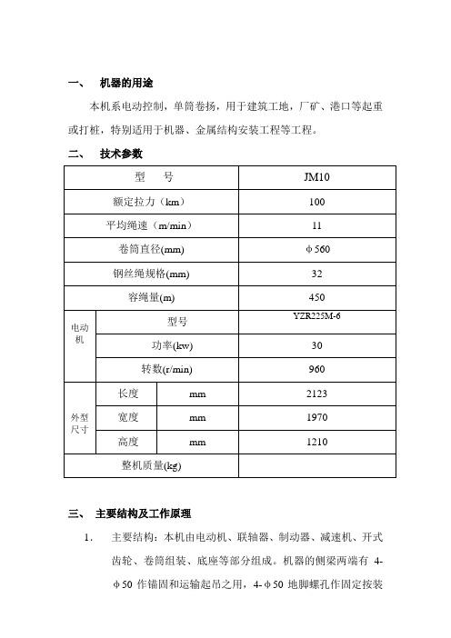
一、机器的用途本机系电动控制,单筒卷扬,用于建筑工地,厂矿、港口等起重或打桩,特别适用于机器、金属结构安装工程等工程。
二、技术参数三、主要结构及工作原理1.主要结构:本机由电动机、联轴器、制动器、减速机、开式齿轮、卷筒组装、底座等部分组成。
机器的侧梁两端有4-φ50作锚固和运输起吊之用,4-φ50地脚螺孔作固定按装用卷筒体与卷筒端盖用6个沉头螺钉连接一体,主轴贯穿其中,卷筒两端籍滑动轴承支承在主轴上,主轴固定在两边支座上,大齿轮与减速机输出轴上的小齿轮相合。
联轴器为带制动轮的弹性柱销联轴器,带制动轮的半联轴器装在减速机输入轴的锥度轴伸端,另一个半联轴器装在电机轴上。
2.工作原理:电机动力经闭式减速机及开式齿轮副减速后,带动卷筒运转。
四、机器结构的说明本卷扬机由机座(1)电动机(2)卷筒(3)联轴器(4)制动器(5)离合器(6)和减速器凸轮控制器(7)电阻器(8)等主要部分组成。
机座的侧栋两端有4个φ50孔可作锚固和动输时提吊之用,4个φ27地脚螺钓孔作固定安装之用。
卷筒体与大齿轮用6个沉头螺钉联接为一整体,主轴贯穿其中,卷筒两端藉滑动轴承支承在主轴上,主轴固定在两边支座上,大齿轮与减速器输出轴上小齿轮相啮合。
联轴器为带动轮的尼龙柱销联轴器,带有制动轮的半联轴器装在减速器输入轴的锥度轴伸端,另一个半联轴器装在电机轴上。
制动器型号YWZ400/90属于常闭式制动器。
减速器型号JZQ650-40.17-3Z,有两级斜齿轮减速,各轴均支承在滚动轴承上,减速器低速轴为改制加长轴外带支承轴轴座。
五、机器润滑范围表六、机器的安装卷扬机在临时安装时,可用机座上φ50的孔用钢绳固定在锚椿上,在固定按装时则用6个M27的地脚螺栓固定在混凝土的基础上,参看按装地基图。
为了保证钢绳在卷筒上正确缠绕,钢绳应以卷筒的下方引出,出绳应水平或接近水平,卷筒主轴到第一个导向滑轮的距离不得少于12米。
七、机器的操作要求1.开车前必须仔细检查各润滑部位,铰链和其它联接,各紧固件是否移动。
使用说明书
卷扬机使用说明在设备吊装过程中,卷扬机直接承受较大的牵力,其安装是否稳固和正确,将危及吊装安全,必须引起我们足够的重视,其安装和使用注意事项如下:1.卷扬机的额定拉力应按照滑轮组跑绳的最大拉力进行选择,选择时应注意,滑轮组跑绳的最大拉力不能大于卷扬机额定拉力的85%;2.对卷扬机的卷筒应进行容绳量校核,容绳量校核是计算卷扬机的容绳量是否大于需要卷入的钢丝绳长度(滑轮组跑绳的拉出长度);3.卷扬机除正常维护、定期检修外,每次使用前应进行检查并试运转,以保证制动系统灵活可靠,运转正常。
并与工作人员取得密切联系及建立联系信号;4.卷扬机使用时应安装在视野良好的地方,操作人员应能直视设备吊装全过程,同时又可以接受指挥信号;5.多台卷扬机同时工作时,要同一指挥,同步操作;6.卷扬机不得超负荷使用;在牵引绳上应装有测力计,用其定期地检测其拉力值;7.用调整导向轮位置的方法,使牵引钢丝绳从卷筒下方绕入卷扬机,以保证卷扬机的稳定;8.卷扬机工作时,为保证钢丝绳固定端的牢固,余留在卷筒上的钢丝绳不得少余5圈;9.应尽可能保证钢丝绳绕入卷筒的方向在卷筒的中部与卷筒轴线垂直,以保证卷扬机受力的对称性,在使用过程中不因受侧向力而发生摆头;10.卷扬机与最后一个导向轮的最小距离不得小于25倍卷筒长度,以保证当钢丝绳绕到卷筒一端时,与中心线的夹角不大于1.5°;11.卷筒上缠绕多层钢丝绳时,应保证钢丝绳始终顺序地逐层紧缠在卷筒上,从而依次排列整齐。
钢丝绳的最外一层应低于卷筒两端凸缘高度一个绳径;12.卷扬机应固定牢靠,严防倾覆和移动,受力时不得横向偏移。
绑缚卷扬机底座的固定绳索应从两侧引出,以防底座受力后移动;13.地锚埋设后应按照其使用负荷进行预拉,必要时应采取加固措施;14.安装卷扬机时要搭设防雨棚避雨。
底座用枕木垫高防潮。
在其底下垫枕木时,枕木不能伸出脚踏制动器一端的底座,以免妨碍操作;15.在使用前应全面检查卷扬机的机械装置和电气系统。
- 1、下载文档前请自行甄别文档内容的完整性,平台不提供额外的编辑、内容补充、找答案等附加服务。
- 2、"仅部分预览"的文档,不可在线预览部分如存在完整性等问题,可反馈申请退款(可完整预览的文档不适用该条件!)。
- 3、如文档侵犯您的权益,请联系客服反馈,我们会尽快为您处理(人工客服工作时间:9:00-18:30)。
高炉卷扬机
玉溪钢厂TBZ120/150--80料车卷扬机
安装维护说明书
北京太富力传机器有限责任公司
目次
1.用途
2.主要技术特性
3.设备构成及注要部件性能
4.安装与调试
5.检修与维护
6.备品备件
7.其它
8.附图
1.卷扬机总装图
2.地基布置图
3.卷筒装置图
1.用途
本卷扬机是北京太富力公司根据玉溪钢厂高炉料车作业要求,专门设计制造的高炉上料设备。
2.主要技术性能
2.1技术性能
2.2电气设备主要性能参数
3.设备构成
本卷扬机主要由机座、电机、减速机、卷筒装置、制动器、联轴器、主令控制器装置、锁紧装置及编码器等部分构成(见卷扬机总图)。
3.1 底座装置
底座直接由钢板焊接而成。
3.2 主驱动器
驱动电机为一台220V交流变频调速电机,自带轴流式冷却风机IC416,其功率550W,三相380V独立电源。
带编码器。
具体内容详见电机生产厂家(使用维护说明)。
3.3 主减速机
主减速机是北京太富力传动机器有限责任公司专门设计制造的减速机,具有体积小,传递扭矩大,过载能力强,安全可靠的特点,其型号为:TJYF600--30减速机,速比:i=30.
3.4 卷筒装置
卷筒装置是由主传动轴、滚动轴承、轴承座、连接链、卷筒及止动盘,固定钢丝绳的压板、螺栓等组成,卷筒装置静平衡后通过轴承座螺栓联接在底座上。
3.5 制动器
本卷扬机配置两台YP2--2000--710x30--I/IIB--H 盘式制动器。
3.6 主令控制装置
一台主令控制器安装在卷扬机主轴端,通过向电控系统发出电流信号控制料车运行位置。
4. 安装与调试
4.1 安装
4.1.1 准备工作:清理基础表面,检查地脚螺栓尺寸是
否符合图纸要求,检查各部件是否安装到位,逐一检查部件螺栓位置是否正常、是否紧固。
4.1.2 将设备运抵安装基础位置。
沿机座周围均匀设置
垫铁,其间距不大于600mm,每块垫铁长乘宽大于200X100,但每条地脚螺栓两侧和轴承中心下必须安装垫铁,机座下面每一条地脚螺栓两侧各垫一组垫铁,两组垫铁地脚中心线为75mm,每组垫铁均应焊固。
4.1.3 卷筒中心线应与高炉中心线找正,沿轴向水平允
差≤0.10/1000mm,垂直于轴向水平度允差≤0.15/1000.
4.2 安装后的清理与检查
4.2.1 将卷扬机上及其附近所有物件清理干净。
4.2.2 检查电动机的接线是否正常;检查电机冷却风机
接线是否正确(风机转动风向)。
4.2.3 检查减速机内是否有异物,润滑油位置是否符合
规定。
润滑油用GB5903中N320号中极压齿轮油。
4.2.4 检查卷筒两主轴承是否加足润滑脂(锂基)。
4.2.5 逐一检查各部件螺栓位置是否正常、是否紧固。
4.2.6 检查制动器、主令控制器、松绳停车装置、卷筒止动装置是否正确。
4.2.7 检查轴承座、轴承盖的安装和密封状况是否正确。
4.2.8 检查确认各部件安装正确,联接紧固后,进行二次灌浆,养护期为30天。
4.2.9 加垫部位,凡在两片或以上者均应点焊加固。
4.3 调试
4.3.1 待二次浇注在混凝土养护期完后,将地脚螺栓再次检查、紧固后,进行调试。
4.3.2 检查二次浇注后,卷扬机各部位是否留有异物并清除,拆开止动盘取下止动销,
4.2.3 检查电动机,制动器;接通电机电源,通电进行正反转式车各五分钟。
4.3.4 接通制动器电源,点动开车进行正反转制动试车各五次,检查并纠正问题。
4.3.5 分步试车后再整体试车,电动机带动减速机及卷筒无负荷正反转各二小时,其中最高速度运转不大于一小时。
4.4 穿钢丝绳
4.4.1 断电,将卷筒止动盘锁定。
4.4.2 检查压板、螺栓、螺母是否完好,数量是否正确,确认后方可穿钢丝绳。
4.4.3 将钢丝绳、压板、螺栓、螺母等按卷筒装置图所示装配,紧固。
缠绳时注意卷筒是左旋双头绳槽,螺距35,导程70,卷筒下放料车达到最大长度后应留有约三圈的安全圈数。
上升、下放绳间一圈绳间距。
4.5 带空车联动空负荷试车
4.5.1 穿上钢绳,挂上料车后,检查空负荷试车前各零件是否正常。
4.5.2 检查正常后,低速运行,试验启、制动灵活,主令控制器信号传输准确无误,松绳报警装置灵敏可靠,再按规定的速度和行程曲线图试车准确无误。
无负荷试车正反转各二小时,检查并纠正问题。
4.6 重车联动负荷试车
4.6.1 在空车无负荷按规定的速度和加速度、行程曲线图试车准确无误后,各零件运作正常,这时可按规定负荷的25%、50%、75%、100%逐级试运转。
有负荷试车前,应先做有负荷的制动器快速制动试验,经确认符合各次规定后即可。
各部件运转平稳,无冲击无不正常噪音各密封处不漏油,轴承温度不超过40°C。
正反转各二小时。
4.6.2 卷扬机安装及试车运转还必须符合GB50231--99,YB5208--85相关规定。
重负荷试车应每隔一小时全面检查各部位螺栓、销、键是否正常。
5.检修与维护
5.1 每天交接班时,必须查看钢绳、压板、及压板螺栓、螺母与卷筒的联接使用说明,必须及时更换损坏的零件。
5.2 经常查看、检听卷扬机各部位的运转是否稳定,发现有异常响声应及时处理(电机、减速机、卷筒、轴承、联轴器、主令、制动器)。
5.3 经常检查各部位联接螺栓、销、键等是否紧固,并
及时紧固。
5.4 减速机内使用的润滑油为N320中极压工业齿轮
油,润滑油应定期更换。
一般新减速机第一次用,运转15--30天后必须更换新油。
5.5 箱体内的水平油标尺处应经常查看,及时加油。
满
载试车时,轴承温升不能超过50°C,润滑油的温升不能超过40°C.
5.6 经常查看卷筒主轴的轴承运行情况,经常加润滑
油,其轴承温升不得超过35°C.
5.7 制动器使用与维护遵照制动器生产厂家《使用与维
护说你书》。
7.其它
7.1 电气操作程序《电气操作维护说明书》,电气专业提供。
7.2 卷扬机提升安全操作见《卷扬机提升安全操作规程》,用户编制。
7.3 本《高炉料车卷扬机使用维护说明书》的最终解释权为北京太富力传动机器有限责任公司。
8.附图
8.1 料车卷扬机总图
8.2 料车卷扬机地脚螺栓布置平面图
8.3 卷筒装置。
