屏蔽罩卡座 使用设计参考
屏蔽壳体设计方案
屏蔽壳体设计方案屏蔽壳体设计方案屏蔽壳体是一种能够隔绝电磁干扰,保护电子设备的外部金属外壳。
在现代电子设备中,由于信号频率越来越高,电磁干扰也越来越严重,因此屏蔽壳体的设计非常重要。
本文将为您介绍一种屏蔽壳体设计方案。
设计方案:1. 材料选择:选择高导电性能的材料作为屏蔽壳体的材料,如铝、铜等。
这样可以提高屏蔽壳体的电磁屏蔽效果,并且减少信号的反射。
2. 结构设计:采用分区结构设计,将屏蔽壳体分为多个区域,每个区域负责屏蔽一个特定的频段。
这样可以有效地降低信号交叉干扰,提高整体的屏蔽效果。
3. 电磁波吸收材料:在屏蔽壳体内部覆盖电磁波吸收材料,可以有效地吸收和消散电磁波。
这样可以进一步提高屏蔽效果,避免信号的反射和漏泄。
4. 连接件设计:选择高质量的连接件,确保连接的可靠性和稳定性。
连接件应具有良好的导电性能,以保证信号的传递和屏蔽壳体的整体性能。
5. 散热设计:屏蔽壳体内部通常会产生大量的热量,因此需要合理设计散热结构,确保设备的正常工作温度。
可以在壳体上预留散热孔或安装散热片等。
6. 外形设计:屏蔽壳体的外形设计应该符合产品的整体风格和美观性,同时要满足设备的尺寸和重量要求。
可以根据需要进行个性化设计,如特殊形状、刻字等。
7. 安全性设计:屏蔽壳体应具有良好的抗冲击、防水、防尘等性能,以保证设备的安全运行和使用寿命。
总结:屏蔽壳体的设计方案涉及多个方面,包括材料选择、结构设计、连接件、散热设计、外形设计和安全性等。
通过合理的设计和选择,可以提高屏蔽壳体的电磁屏蔽效果,保护电子设备免受电磁干扰的影响,确保设备的正常工作。
屏蔽罩设计总结范文

屏蔽罩设计总结范文一、引言屏蔽罩是一种用于阻隔电磁辐射的设备,广泛应用于电子设备、通信设备等领域。
在屏蔽罩的设计过程中,需要考虑到多个因素,包括材料选择、结构设计、加工工艺等。
本文将对屏蔽罩设计的要点进行总结。
二、材料选择1.导电性好:屏蔽罩需要能够有效地导电,将电磁辐射引导到地面。
因此,在材料选择时,应优先考虑导电性好的材料,如铜、铝等金属材料。
2.塑料屏蔽罩:当屏蔽要求不高时,塑料屏蔽罩是一种经济实用的选择。
其中,利用抗静电塑料制作屏蔽罩,不但节省成本,还能避免因静电引起的故障。
三、结构设计1.可拆卸结构:屏蔽罩往往需要进行检修和维护,因此,在设计时应考虑到方便拆卸的要求,便于操作人员进行维护。
2.接地设计:屏蔽罩需要与地面建立良好的接地,以便将电磁辐射导入地面。
因此,设计时应注重接地设计,确保屏蔽罩能够起到有效屏蔽的作用。
3.结构紧凑:为了优化空间利用率,屏蔽罩的设计应尽量紧凑,减少占地面积。
此外,结构的紧凑性还能提高屏蔽效果,减少信号的泄漏。
四、加工工艺1.数控加工:屏蔽罩的结构往往较为复杂,因此,采用数控加工工艺能够提高加工精度和效率。
2.冲压工艺:适用于较薄的金属材料制作屏蔽罩,能够实现批量生产和降低成本。
3.表面处理:屏蔽罩的表面处理可以增加其耐腐蚀性和美观性。
常用的表面处理方法包括电镀、喷涂等。
五、应用领域1.电子设备:屏蔽罩广泛应用于各类电子设备,如计算机主机、电视机、手机等。
它们能够有效地抑制电磁辐射,确保电子设备的正常工作。
2.通信设备:在通信设备中,屏蔽罩能够减少干扰,提高通信质量。
例如,手机信号的屏蔽罩能够有效阻隔外界干扰,提供更好的通信体验。
3.医疗设备:医疗设备尤其是敏感的医疗仪器,需要经过屏蔽罩的保护,以防止外界电磁辐射对其造成的干扰。
六、总结屏蔽罩作为一种能够阻隔电磁辐射的设备,在现代社会中得到了广泛的应用。
通过合理的材料选择、结构设计和加工工艺,可以实现高效的屏蔽效果。
手机PCBA屏蔽罩设计参考
⼿机PCBA屏蔽罩设计参考结构设计规则(2)屏蔽罩及其焊盘设计版本:01⽇期:2003,8,1作者:孙继群SMT 屏蔽罩是造成主板SMT 不良的最主要的因素之⼀,为了降低与其有关的制造成本增加,SMT 屏蔽罩的数量/⼤⼩/复杂程度等需要满⾜以下要求并最终得到各相关部门(硬件,⼯艺,品质,采购等)的确认。
屏蔽罩设计1.屏蔽罩设计的单边最⼤尺⼨为30mm,并要求形状尽量⽅正,避免因拐⾓引起过⼤的缝隙;2.屏蔽罩在平⾯中⼼部位要保留有⽤于真空吸附⾃动拾取的位置,该位置要求平整,⽆开孔,直径不⼩于6mm,且该中⼼要求尽量靠近屏蔽罩的⼏何中⼼,并便于识别。
3.屏蔽罩上表⾯应留有3个定位孔⽤于精确定位,定位孔要求位于对⾓或边界位置,建议直径1.2mm(孔⼤⼩尺⼨为1mm到1.5mm),且距离屏蔽罩侧壁和任⼀开孔距离不⼩于2mm(如下图)。
定位孔的建议公差不⼤于+/-0.13mm (基于屏蔽罩的壁厚)。
4.对于⾯积较⼤的屏蔽罩,其(真空吸附)⾃动拾取点距离定位孔不超过15mm,以⽅便定位识别。
5.屏蔽罩上⾯需要设计⼀些通孔以⽅便在回流焊后⽬视检查和分析被屏蔽的器件,这些孔也利于在回流炉中各器件获得更均衡的温度。
建议开孔直径1.2mm,孔间中⼼距8.0mm,屏蔽罩的设计必需经硬件,⼯艺部门确认。
6.建议屏蔽盖材料:厚度0.2mm,洋⽩铜 Cu-C7521 1/2H; 若是两件式,则屏蔽盖的屏蔽框⽤0.20mm厚的Cu-C75211/2H,屏蔽盖的顶盖⽤0.15mm厚的SUS304 。
7.屏蔽罩平⾯度⼩于0.1mm。
8.屏蔽罩侧壁不能有折弯焊脚的设计,以避免影响平整度和回流焊质量;9.屏蔽盖的⼤⼩尺⼨不能超过35mm*35mm,最⼤边长度不能超过35mm。
10.对于MTK平台和⼀般功能模块,屏蔽罩侧壁采⽤城墙式设计,缺⼝⾼度最⼤不能超过0.3mm(若表层有RF阻抗线穿过屏蔽盖,则此缺⼝⾼度为0.4mm,其他仍为0.3mm),侧壁最⾼不超过3mm,拐⾓处缝隙为0.1mm。
PCB layout设计的屏蔽罩设计规则
屏蔽罩位置及大小,形状,一般由硬件工程师来确定,画出一定的形状,然后由结构设计来画出屏蔽罩的详细的立体结构调整图.屏蔽罩的焊盘宽度一般取0.6mm----0.8mm屏蔽罩的焊盘长度一般取3---5mm,一般取5mm左右,不然太零散了.屏蔽罩的焊盘间距一般取1mm.注意,屏蔽罩的焊接脚,就是长城脚,长度可以和焊盘一般长,这里要求不高.硬件工程师,按以上方法操作,那么他就会按照元件焊盘离屏蔽罩的焊盘间隙保持在0.3mm以上,往里面塞元件.算屏蔽罩的高度时候,按最高的元件的最大公差画出元件高度就可以了,不必要留锡膏的厚度尺寸.因为钢网厚度也就才0.1mm,不贴元件,锡膏也就是0.1mm高,而贴元件后,元件还要陷到锡膏里面去呢.再说,元件的高度,基本上都按其下差做的.然后根据最高元件的顶面到屏蔽罩内表面间隙取0.2mm,这样算出屏蔽罩的高度就可以了.屏蔽罩设计的要点 (2010/04/23 09:23)目录:公司动态浏览字体:大中小屏蔽就是对两个空间区域之间进行金属的隔离,以控制电场、磁场和电磁波由一个区域对另一个区域的感应和辐射。
具体讲,就是用屏蔽体将元部件、电路、组合件、电缆或整个系统的干扰源包围起来,防止干扰电磁场向外扩散;用屏蔽体将接收电路、设备或系统包围起来,防止它们受到外界电磁场的影响。
因为屏蔽体对来自导线、电缆、元部件、电路或系统等外部的干扰电磁波和内部电磁波均起着吸收能量(涡流损耗)、反射能量(电磁波在屏蔽体上的界面反射)和抵消能量(电磁感应在屏蔽层上产生反向电磁场,可抵消部分干扰电磁波)的作用,所以屏蔽体具有减弱干扰的功能。
(1)当干扰电磁场的频率较高时,利用低电阻率的金属材料中产生的涡流,形成对外来电磁波的抵消作用,从而达到屏蔽的效果。
(2)当干扰电磁波的频率较低时,要采用高导磁率的材料,从而使磁力线限制在屏蔽体内部,防止扩散到屏蔽的空间去。
(3)在某些场合下,如果要求对高频和低频电磁场都具有良好的屏蔽效果时,往往采用不同的金属材料组成多层屏蔽体。
屏蔽盖拉深模具设计说明书
题目屏蔽盖零件拉深模具设计第一章审图由工件图可知,该工件为不带凸缘的开口对称盒形件,且中心有内孔翻边的要求,需保证外形尺寸,没有厚度不变的要求。
该工件形状满足拉深工艺性要求和内孔翻边要求,可用拉深和翻边工序同时加工完成。
材料为08F钢,料厚为1mm。
拉深精度等级为IT10第二章拉深工艺性分析2。
1对拉深件形状尺寸的要求1)拉深件形状应尽量简单、对称,尽可能一次拉深成形;2)尽量避免半敞开及非对称的空心件,应考虑设计成对称(组合)的拉深;3)在设计拉深件时,应注明必须保证外形或内形尺寸,不能同时标注内外形尺寸;带台阶的拉深件,其高度方向的尺寸标注一般应以底部为基准;4)拉深件口部尺寸公差应适当。
5)一般拉深件允许壁厚变化范围0.6t~1。
2t,若不允许存在壁厚不均现象,应注明;6)需多次拉深成形的工件,应允许其内、外壁及凸缘表面上存在压痕.7)拉深件口部应允许稍有回弹,但必须保证装配一端在公差范围之内。
2。
2 拉深件材料性能1)具有较大的硬化指数;2)具有较低的径向比例应力σr/σb峰值3)具有较小的屈强比σs/σb;4)具有较大的厚向异性指数r.2.3 拉深件的精度等级要求不宜过高主要指其横断面的尺寸精度;一般在IT13级以下,不宜高于IT11级,高于IT13级的应增加整形工序。
因为工件图精度等级为IT10,所以符合要求。
2.4 拉深件的材料由工件图可知拉伸件所用的材料为08F钢。
表2-12.5 拉深件工序安排的一般原则l)在大批量生产中,在凹、凸模壁厚强度允许的条件下,应采用落料、拉深复合工艺;2)除底部孔有可能与落料、拉深复合冲压外,凸缘部分及侧壁部分的孔、槽均需在拉深工序完成后再冲出;3)当拉深件的尺寸精度要求高或带有小的圆角半径时.应增加整形工序;4)修边工序一般安排在整形工序之后;5)修边冲孔常可复合完成.第三章拉深工艺方案的制定根据工件图和要求知,该工件只需拉深工序,可采用单工序拉深模。
关于数码电子产品结构设计规范

关于数码电⼦产品结构设计规范1基本设计注意事项:1:在外观设计前需对ID图的每个细节有详细的了解(如:每个零件在模具上是否能实现;在结构设计上是否能达到和⾃已的想法⼀致;在⼯艺上是否能做到;必须保证有⾜够的把握。
)2 : 如果ID设计很理想化时,需同ID⼯程师及时沟通,直⾄达成⼀致,(如:能不能过静电测试;跌落测试;拉⼒、扭⼒测试等等)。
3:在外观设计时要为结构设计打下基础(如:间隙、胶厚、为结构上的设计预留⾜够的空间等等)。
4:在外观设计时需考虑到ID效果,尽量接近ID图。
5:在外观设计时需考虑每个零件拆件⽅式和每个零件的位置是否正确(如:螺丝柱的位置;RF测试孔的位置及⼤⼩;LCD显⽰区域;摄像头、⽿机孔、按键、输⼊输出接⼝、MIC的位置等等)。
2基本胶厚设计:基本胶厚做到1.2mm~1.8mm左右;直板机侧⾯胶厚尽量做到1.5mm左右,为了便于⽌⼝设计和保证整机强度 (注:侧胶位与基本胶厚相接处需顺滑过渡);翻盖机和滑盖机胶厚做到1.20mm左右;装饰件胶厚需做到0.8mm以上(特殊情况除外)。
3产品外观⾯胶厚设计(⼀):⼤件产品外观胶厚设计参考要求如下:a. 最⼤胶厚值:A ≤1.8mmb. 平均胶厚值: 1.2mm≤B≤1.5mmc. 最⼩胶厚值:C≥0.7MM(⾯积不能太⼤,顺滑过渡)4产品外观⾯胶厚设计(⼆):壳体装饰件和电池盖等零件.如尺⼨较⼤,材料为:PC时,壁厚需设计到1.0mm以上.5胶位厚薄过渡设计:壳体第⼀外观⾯相应的后模偷胶位尺⼨如果超过均匀胶厚的1/3以上,需做顺滑过渡(常发⽣于扣位周围,⽌⼝处,底壳喇叭避空位,⾯壳按键避空位,电池盖电池避空位等),⾮外观⾯胶位厚度尽量不要超过1/2.6加强筋设计:为确保塑件制品的强度和刚度,⼜不致使塑件的壁增厚,⽽在塑件的适当部位设置加强筋,不仅可以避免塑件的变形,在某些情况下,加强筋还可以改善塑件成型中的塑料流动情况。
为了增加塑件的强度和刚性,宁可增加加强筋的数量,⽽不增加其壁厚。
7.屏蔽罩设计
7.屏蔽罩设计
一、概述
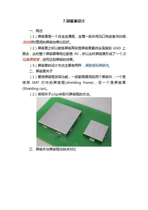
(1)屏蔽罩是一个合金金属框,金属一般采用马口铁或者洋白铜,洋白铜对高频的屏蔽效果比较好。
(2)屏蔽罩之所以能够屏蔽其实是屏蔽罩最终会连接到GND上面去,此时整个屏蔽罩等电位都是0V,所以此时屏蔽罩形成了一个法拉第屏蔽笼,进而达到屏蔽的效果。
(3)屏蔽罩的设计方式主要有两种:屏蔽框和屏蔽夹。
二、屏蔽罩夹子
(1)要使屏蔽框发挥功能,一般都需要用到两个零部件,一个是使用SMT打件的屏蔽框(shielding frame),另一个是屏蔽罩(Shielding can)。
(2)使用夹子(clip)来取代屏蔽框的方法。
三、屏蔽夹与屏蔽框优缺点对比
四、屏蔽夹方式设计屏蔽罩时的技术要求
(1)每个夹子的对屏蔽框的夹持力约为1 kgf,一般来说一个屏蔽框通常最少需要4个夹子来固定其位置。
(2)每个夹子所能承受的推力为5kgf 以上。
(3)以手机为例,大约25mm 摆放一个夹子就可以了。
(4)吃锡厚度最好在0.1mm,太厚的话怕屏蔽框与电路板的中间会出现较大的空隙,影响EMI的效果。
五、屏蔽罩的应用
(1)常常需要屏蔽的模块主要有:电源模块(PMU+DCDC+LDO)、核心模块(CPU+DDR+Flash)、WiFi以及蓝牙模块、音频模块等。
同时,在PCB设计中最好做屏蔽罩预留设计。
(2)屏蔽罩尽量设计为矩形,不要出现多边形的情况,以免加大生产难度。
PCB主板屏蔽罩如何设计效果好
目前,更有一些客户要求越来越高,开始使用一些拉伸的屏蔽罩,这对深圳屏蔽罩 厂家来说,也蔽效 果。
分享者:诚瑞丰公司
屏蔽罩的用途越来越广泛,不同的产品就有不同的要求。但确认材质与厚度是对深 圳屏蔽罩厂家的关键。普遍的材质是0.2mm和0.15mm洋白铜,也有马口铁,如果 是屏蔽架外扣屏蔽罩的二件式,一般材质是支架洋白铜,上盖不锈钢,这种二件式 的,在售后折装和维修上有很大方便。
重要一点,因屏蔽罩大多都是SMT自动贴片,所以在设计屏蔽架支架时,中心点一 定要留个吸嘴位置。曾有个客户就咨询过群哥这个别的工厂做的人才事怎么解决。 后面就直接与群哥家合作了。
深圳市诚瑞丰科技股份有限公司
主营:五金冲压件、钣金加工、冲压模具设计
PCB主板屏蔽罩如何设计效果好
无数次的接到过一些客户在设计屏蔽罩时,因为不太清楚深圳屏蔽罩厂家的模具生 产实际情况,造成一些时间的影响。也有些客户在当初做屏蔽罩图纸设计时,也有 一些模糊的问题。冲压群哥,用实际经验和您谈谈如何在屏蔽罩设计中提升工作质 量。
手机屏蔽罩开模工艺性要求精编版
屏蔽罩开模工艺性一.产品材料(供参考)产品一般采用材料洋白铜C7521R-1/2H。
㈡屏蔽罩产品结构1,四方形屏蔽罩设计时须具有防反(最好是中心对称,包装具备任意性)。
①产品在包装时产品方向易包错,②产品贴片时易贴错。
2,局部的缺口不可太小,一般最窄为0.8MM;①模具的制造周期会加长,制造陈本增加。
②模具量产时,冲子的强度较弱易损坏,备件加工周期长可能会影响到出货。
3,如下料刀口到折弯边余料较小时:Ⅰ将下料刀口开至折弯边;Ⅱ将下料刀口到折弯边余料加到大于等于0.5MM。
①材料距折弯边较少,不方便产品压料成型,产品易变形。
4,产品表面有散热孔时,建议选用∮1.0mm, ∮1.2mm, ∮1.5mm, ∮2.0mm标准。
①我司备有这些常用孔冲针的标准件,可以缩短模具制造周期。
②量产中,圆冲有损坏可以马上更换,不影响交货。
5,四方形屏蔽罩相邻两折弯边间隙不可等于本产品的料厚。
①产品冲制时,产品与产品容易扣合在一起。
②最好间隙为:0.15<H<T6,带外趴脚产品:⑴在做可靠性实验时屏蔽罩的最大受力区域加外趴脚即可。
一般受力点在最长的对角线两端。
建议①长.宽25MM以内的不需加外趴脚。
②长.宽25~35MM以内的加两个外趴脚,放在产品的对角(如左上角和右下角)。
③长.宽大于35MM加四个外趴脚,放在产品对角。
(如左上角,左下角,⑵外趴脚的长和宽尺寸在1.0~1.2MM*1.5~2.5MM①长度太长容易变形,且占用PCB板空间。
②宽度太小强度越差则容易外趴脚变形。
⑵焊锡性,在趴脚末端加工内凹的半圆形状,可以加强焊锡强度。
7,建议产品不要采用内趴脚。
①产品内趴脚强度弱,易变性,影响焊锡性。
②不方便检测产品的平面度。
③内趴脚会增加模具的工站,模具的长度增长,加大了产品生产的难度。
屏蔽罩结构设计指导
屏蔽罩结构设计指导屏蔽罩是一种用于隔离和保护电子设备免受外部电磁干扰的建筑结构。
它通常由金属材料制成,如铁、铝或铜等,具有良好的导电性和屏蔽性能。
下面是一些屏蔽罩结构设计的指导原则,以帮助您设计出高效可靠的屏蔽罩。
1. 材料选择:选择具有高导电性和良好屏蔽性能的材料非常重要。
常见的金属材料,如铁、铜和铝等,通常被广泛应用于屏蔽罩的制造。
材料的厚度也要合适,一般在0.5mm至1.5mm之间。
2.结构形式:屏蔽罩的结构形式可以是盒状、套筒状或者是各种其他形式。
选择适合实际应用的结构形式,能够更好地满足对屏蔽的要求。
3.接地设计:接地是屏蔽罩性能的关键因素之一、合理配置接地装置,确保罩体的有效接地,是防止来自外部电磁干扰的重要手段。
通过接地将电磁波的能量导入到大地中,减小对内部设备的影响。
4.导电连接:屏蔽罩的导电连接要保证电流的连续性和通畅性,以减小电阻对屏蔽效果的影响。
所选用的导电连接件要具有足够的导电性能。
5.缝隙和接缝:屏蔽罩的缝隙和接缝需要严密封闭,以防止电磁波的泄漏。
可以通过采用磁屏蔽嵌条、导电胶水等方式,对缝隙进行处理,确保屏蔽效果。
6.通风设计:考虑到设备内部的散热需求,屏蔽罩需要设计合理的通风结构。
通风口的位置和大小要进行合理安排,既能满足散热要求,又能保证足够的屏蔽效果。
7.尺寸和形状:根据实际需求,确定屏蔽罩的尺寸和形状。
尺寸要足够容纳设备,并留有一定的余量。
同时,形状也要便于安装和维修。
8.表面处理:在屏蔽罩制造完成后,进行表面处理是非常重要的。
表面要进行光滑处理,以减小电磁波的反射和散射。
9.避免电流环:在设计屏蔽罩时,应该避免电流环的产生。
电流环是指在导电件表面形成的电流路径,可以降低屏蔽效果,对设备的性能产生负面影响。
10.可拆装设计:考虑到设备的维修和更换,屏蔽罩的设计应该便于拆卸和组装。
可以采用螺栓或者卡槽等连接方式,使得罩体能够方便地拆卸和组装。
总的来说,屏蔽罩的设计需要综合考虑各个因素,以达到良好的屏蔽效果和工程可行性。
屏蔽罩知识培训培训课件
机械性能
电磁兼容性
屏蔽罩需要具备一定的机械性能,如抗拉 强度、抗压强度、耐磨性等,以确保在使 用过程中不易损坏。
屏蔽罩需要具备较好的电磁兼容性,能够 有效抑制电磁干扰,提高设备的电磁稳定 性。
屏蔽罩性能测试报告的解读与使用
01
报告解读
对屏蔽罩性能测试报告进行详细解读,了解测试结果和各项指标的具体
含义。
屏蔽罩的分类
按材质分类
金属屏蔽罩、塑料屏蔽罩、陶瓷 屏蔽罩等。
按结构分类
整体式屏蔽罩、组装式屏蔽罩等。
按应用分类
手机屏蔽罩、电脑屏蔽罩、家用电 器屏蔽罩等。
屏蔽罩的应用领域
通信领域
手机、无线电等通信设 备需要使用屏蔽罩来降
低电磁干扰和辐射。
电子设备领域
电脑、家用电器等电子 设备需要使用屏蔽罩来 提高稳定性和可靠性。
THANKS
谢谢您的观看
屏蔽罩的加工工艺
01
02
03
04
切割与拼接
根据设计图纸,使用切割工具 将材料切割成所需形状,然后
进行拼接。
焊接与铆接
对于需要连接的部位,可以采 用焊接或铆接的方式进行固定
。
表面处理
为了提高屏蔽效果和美观度, 可以对屏蔽罩表面进行镀层处
理或喷涂处理。
检测与测试
在加工完成后,应对屏蔽罩进 行检测和测试,以确保其符合
安装过程中的注意事项
按照说明书逐步安装
01
按照产品说明书逐步安装屏蔽罩,确保每个部件都正确安装,
避免出现漏装或错装的情况。
注意安全
02
在安装过程中要注意安全,避免出现意外伤害。
保持清洁
03
在安装过程中要保持屏蔽罩的清洁,避免灰尘或其他杂质进入
电磁屏蔽罩的设计-简述
Shielding Case材质介紹(二)
材料
价格 抗氧化程度 表面
裁切面 Reflow变色 吃锡性 应力分布
C7521(三菱) *****
C7521(一般) ****
SPTE
*
佳
不易氧化 不易氧化 不会 70~80% 均勻
会
佳
不易氧化 不易氧化 (超过280度变色, 70~80%
均勻
但不影响功能性)
Shielding Case核心要素
• 材质 •形式 (几乎无弹性 不会因使用而作动)Shieding Case材质介绍(一)
项次 FRAME
COVER
材料 C7521(洋白铜) _ 三菱 C7521(洋白铜) _ 一般 SPTE (马口铁) / KU360S (雾面马口铁)
ZSNH (锌锡镍合金) C2680(铜合金)
价格低
*裁切面易氧化 *易聚磁
Shielding Case型式
两件式(COVE+FRAM)
一件式
一件式(COVER+CLIP)
Shielding Case型式(一)
TYPE
COVER+FRAME (两件式)
优差比较
(Cost以COVER+CLIP为基数,
1.2
其他为相对于“大约"成本比 )
优点
估价基准项目 1.两件式 2.一件式 3.Cover+8个clip
Thank You !
差
易刮伤氧化 易氧化
不会
优
均勻
SUS
**
ZE-38
***
ZSNH
***
C2680镀雾锡 ****
优 中等
差
屏蔽室设计方案B级不锈钢网

电磁屏蔽室设计方案一、设计依据1.《军用电磁屏蔽室通用技术要求和检验方法》GJBz20219-942.《高性能屏蔽室屏蔽效能的测量方法》GB12190-90二、设计方案1、技术要求1.1屏蔽性能:参照GJBz20219-94《军用电磁屏蔽室通用技术要求和检测方法》的B级屏蔽室的技术要求设计施工。
其屏蔽效能如下:1.2采用多点接地。
2.建造规模屏蔽室尺寸分别为:L×W×H=7450×14710×2600L×W×H=3100×11496×2600L×W×H=8050×10050×2600屏蔽门的尺寸:屏蔽室设手动屏蔽门三樘,尺寸为W×H=800×1800。
3.结构设计3.1屏蔽主体结构本屏蔽室采用双层不锈钢网密封结构,钢骨架采用50×50的木龙骨。
3.2屏蔽门设计方案书- 1 -安全屏蔽门共3樘,手动锁紧,双开,净开尺寸为W×H=800×1800屏蔽门的结构形式为手动平开闸刀式屏蔽门;屏蔽门采用单刀双簧结构形式即满足屏蔽室的屏蔽性能为大于50dB(满足国军标B级),屏蔽门采用的梳形弹簧片是可拆卸式美国泰克尼特产品,具有弹性高、粘贴均匀、抗疲劳性强和导电性能好的优点。
性能稳定、使用可靠、维修方便。
4.配供电和照明系统4.1配电控制柜布置进入屏蔽室的电源从屏蔽室外配电柜引出,配电柜由甲方提供,设置屏蔽间附近,屏蔽室内的配电箱设置在室内门口附近。
屏蔽室内用电应分相处理。
4.2电源滤波器屏蔽室的所有电源均需通过电源滤波器引入到室内的配电箱。
2只电源滤波器安装在屏蔽室的顶部。
5.通风空调系统由于采用了不锈钢网作屏蔽壳体材料,屏蔽室通风换气不需要通过蜂窝状通风截止波导窗进行。
由于甲方在屏蔽室内放置两台空调,我方负责空调的过壁系统。
6.消防报警系统屏蔽室设1个感烟探头,感烟探头经屏蔽专用火警传递器引出屏蔽室接入值班室的报警控制器。
屏蔽罩多工位级进模设计
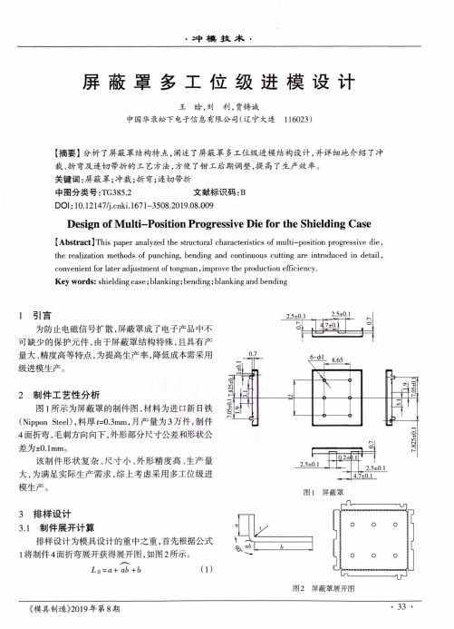
•冲棋技术・屏蔽罩多工位级进模设计王啥,刘利,贾铸诚中国华录松下电子信息有限公司(辽宁大连 116023)【摘要】分析了屏蔽罩结构特点,阐述了屏蔽罩多工位级进模结构设计,并详细地介绍了冲裁、折弯及连切带折的工艺方法,方便了钳工后期调整,提高了生产效率。
关键词:屏蔽罩;冲裁;折弯;连切带折中图分类号:TG385.2 文献标识码:BDOI :10.12147/j .cnki. 1671-350& 2019.0&009Design of Multi-Position Progressive Die for the Shielding Case[Abstract] This paper analyzed the structural characteristics of multi-position progressive die,the realization methods of punching, bending and continuous cutting are introduced in detail ,convenient for later adjustment of tongman , improve the production efficiency.Key words : shielding case ; blanking ; bending ; blanking and bending1引5为防止电磁信号扩散,屏蔽罩成了电子产品中不可缺少的保护元件,由于屏蔽罩结构特殊,且具有产 量大、精度高等特点,为提高生产率,降低成本需采用 级进模生产。
2制件工艺性分析图1所示为屏蔽罩的制件图,材料为进口新日铁(Nippon Steel ),料厚«=0.3mm,月产量为3万件,制件 4面折弯,毛刺方向向下,外形部分尺寸公差和形状公差为 ±0.1mm 。
该制件形状复杂、尺寸小、外形精度高、生产量 大,为满足实际生产需求,综上考虑采用多工位级进模生产。
屏蔽罩设计总结
屏蔽罩设计总结上海手机结构部吕有刚介绍当今复杂的电子技术引发了多种设计的挑战性,在解决EMI的同时,需要平衡其对空间,重量以及生产带来的负面影响.当制定一种解决方案时,在应用设计阶段早期介入将有助于在解决EMI的同时满足所有其它的要求.相关概念屏蔽-----阻碍静电对电子器件正常工作的影响EMI-----电磁干扰RFI------射频干涉屏蔽性能的对比屏蔽罩设计注意点屏蔽罩结构简洁,尽可能减少不必要的空洞,尽可能不要增加而外的缝隙.避免开细长孔,通风孔尽量采用圆孔并阵列排放.屏蔽和散热有矛盾时,尽可能开小孔,多开空,避免开大孔.屏蔽罩的连续型是影响结构件屏蔽效能最主要的因素,相对而言,材料本身的屏蔽性能的影响微不足道.屏蔽罩的分类⒈ 单片屏蔽罩 ⒉ 两片型屏蔽罩0.010.1110100110100100010000Frequency [MHz]W a v e l e n g t h [m ]MHz the屏蔽罩的材料屏蔽罩材料参数原材料厚度(mm)热处理电镀注释CDRS冷扎钢板0.127to2.286无热处理锡预镀铍-铜合金0.127to0.406中热处理完全可软焊pre-plated镍白铜0.102to0.305加负退火铜基合金0.152to1.524无热处理对于SMT可焊性无需电镀单片式屏蔽罩的设计屏蔽罩上开孔的设计1开孔直径为1mm≤φ≤3mm (考虑RF原因)2孔间距的设计根据加工要求确定3开孔改善散热性能以及可以使仪器通过孔直接对电子器件作测试4开孔会增加产品成本单片屏蔽罩提供六面保护,第六面是印刷电路板本身.单片屏蔽罩设计提供了经济的选择,并具有良好的屏蔽效果.其缺点是修理比较困难.两片式屏蔽罩屏蔽支架的设计长城槽的尺寸 L=3mm*H=0.5mmLIP的设计尺寸l≥1.00mm最佳为1.50mm夏新手机贴片时焊锡厚度在0.15—0.20mm,设计长城槽便于锡膏爬上屏蔽罩,防止其偏移和虚焊RUBLE转角的设计降低转角缝隙,改善屏蔽性能可以根据屏蔽支架的高度和最小缝隙来确定凸台的数量应用于转角缝隙大于2.5mm的两片式屏蔽支架和单片式屏蔽罩吸盘区域的设计要点直径为6mm为最佳(也可以设计更小,但会影响贴片速度及价格)吸盘为应位于屏蔽支架的中心位置屏蔽支架的横梁设计是便于后续的维修以及检测电子器件建议宽度为0.50mm两片式屏蔽罩的设计两片式屏蔽罩便于方便灵活低检验和修理被屏蔽罩盖住的电子元件.在修理时,可取下屏蔽罩盖子更换元件即可,而无需冒由于焊掉整个屏蔽而损坏面板和其它电子元件的危险.使得修理更快捷,容易.并且减少电路板的返修率.两片金属屏蔽罩可分为预装配和非预装配两种.在盖子上设计有大小两种凸点,当盖子和支架结合时,大凸点镶入插槽以提供定位力.小凸点与支架接触以达到良好的接地和防止发生咯吱声.装配间隙0.1mm,就是为了便于装配,防止零间隙会有干涉盖上的大凸点直径为0.8mm,高度0.35mm小凸点直径为0.6mm,高度0.25mmEZ PEEL在电路板维修率较低的情况下,一种经济的解决方案是采用EZ PEEL屏蔽罩.这种屏蔽罩的特点是,使用简单的工具将其顶部的部分剥离以达到修理元件的目的.修理完毕厚,可盖上为其特别设计的盖子.多腔屏蔽罩的设计带有多个电路组合的印刷电路板引发了独特的屏蔽罩设计.多腔屏蔽罩被分隔为几个腔体,容许用一个多腔屏蔽罩取代两个以上单个屏蔽罩.即减少了电路板的零件数,同时减少了生产时间.这样能减少库存中的部件数目,从而降低总开支.多腔屏蔽罩内部分隔成若干个腔,其分隔墙只有一个料厚.从而满足FCC,VDE,CISPR以及CE对屏蔽罩的要求.多腔屏蔽罩是两片型屏蔽罩,可分为预装配的和未预装配的.为保证平整度符合要求,在多腔屏蔽罩在被包装前,应对其100%的检测,包括中间任何一道隔墙拉伸型金属屏蔽罩随着微处理器运算速度的持续增加,由屏蔽罩中微笑缝隙造成的EMI泄漏也随着频率的增加而增加.拉伸型屏蔽罩能在更高的频率环境下提供而外的近场和远场电路的隔离(衰减),以消除因传统金属屏蔽罩转角中的缝隙而造成的泄漏.拉伸型屏蔽罩采用小的拉伸轮廓,从而保持屏蔽罩内的空间.在更高频率下需要额外的电路隔离(衰减)时的封闭转角设计屏蔽罩高度可达到6.4mm以及长度和宽度尺寸从7.6mm到50.8mm材料:马口铁,黄铜制品,不锈钢和镍白铜结合折弯方式,可以得到拉伸型多腔屏蔽罩可以与注塑件结合起来以达到一个多用的目的可做成带由EZ PEEL特征,易于撕去顶部以方便维修,并可重新密封.封装方式封装方式有托盘和载带两种方式前者的价格较低,对于屏蔽支架来说需要保证平整度一般建议采用载带的封装形式手机工艺的建议根据工艺要求转角处不能没有间隙。
屏蔽罩夹子应用设计指导

屏蔽罩夹子应用设计指导POCONS CO.,LTDSHIELD CAN CLIP ENGINEERING GUIDE 屏蔽罩夹子应用设计指导2011.03vShield Can Clip (PTC Series)[ Major Application ]Cellular Phone PMP WIBRO USB DONGLE GPS MODULE NAVIGATION HSUPA / HSDPA module MP4 PON HIPASS UMPC [ Key Features ]Efficient use of the PCB space T o increase productivity by mounting the Clip automatically Reduction in the term and the expense for the development by removing the frame Cost reduction Efficient purchase by standardization Easy repairs 2Pocons中国区代理速盈科制作vApplication exampleShield Can ClipEmbossingHOLEEmbossing Clip3Pocons中国区代理速盈科制作vAppilcation notel l l l lBig size shield can which cover whole PCB had betterseparate to 2 piece of shield can. The minimum gap size between clip and clip is 0.3mm. The clip pad keeps 0.5mm distance from PCB edge. Clip should be separated from Magnetic strip components as far as possible. When the gap size between shield Can and plastic cover is less than 0.2mm, it is perfect for drop test.Pocons中国区代理速盈科制作4vUnderfilll l l l lWhen you artwork clip at near memory chip 1) in case of sealing with “resin”, keep 0.4mm distance from IC 2) in case of no sealing, 0.15~0.2mm distance from IC is enough * Sealing with Resin, they call “ underfill” for protecting memory on drop test Pocons中国区代理速盈科制作5vClip placementCase 1) when designing PCB with 4 pcs of clip Do not place the clip at the center position. Because it is not perfect for drop test and inserting shield can by manual. Recommended placement) It is good for assembly and drop testPocons中国区代理速盈科制作6vClip placementCase 2) artwork with 6 pcs of clipCase 3) artwork with 10pcs of clip especially in RF part More clip is better for EMI shieldingPocons中国区代理速盈科制作7vClip application noteCase 4) With screw When designing PCB with big shield can, you can use clip and screw at the same timeScrew holePocons中国区代理速盈科制作8vShield Can design referenceWhen you use our clip, you’d better cut out 0.27~0.30mm height, 7mm length of can(refer to the drawing below) which is part of clip and can contactedPocons中国区代理速盈科制作9vApplication ezxample for base bandAs you can see, you can use the PCB space efficiently in base band part.Pocons中国区代理速盈科制作10vclip placement Guide considering Noise emmission ?Clip should be placed within 20mm distance not to affect the wireless sensitivity - If shield can side length is less than 20mm, then clip should be placed at center. - When you consider assembly, clip should be placed within 5mm distance from corner. - Clip should be placed at shortest distance from hot spot.Without SHIELD CAN Frame type SHIELD CANCLIPGSM850 PCS110dBuV 105dBuV93dBuV 80dBuV90dBuV 82dBuVaccording to the evaluation result, both have same shield effectiveness.Pocons中国区代理速盈科制作11vAppendixITEM SPEC- More than 3 kgfPCBMethod-ResultMax : 5.2 kgf Min : 4.2 kgf AVG : 4.6 kgfPeeling strength (Lateral force)GageClipPushFlexural Strength (Twist test)- Do not drop out (twist 1mm)GoodInsertion/Rete ntion force- Insertion force : less than 1,000g - retention force : more than 60g- measure the force after 10 cycles(inserting and pulling out) ( Can Thickness : 0.2T )-Insertion force : 420 g -retention force : 118 g Contact resistance- 100 m? Max-After inserting shield Can-Max : 34 m? Min : 26 m? AVG : 30 m? Pocons中国区代理速盈科制作12vAppendixPocons中国区代理速盈科制作13。
屏蔽罩冲压件模具设计.
毕业设计说明书题目:屏蔽罩冲压工艺及模具设计年级、专业:姓名:学号:指导教师:完成时间:摘要冲压模具在工业生产中应用广泛。
冲压模具的设计充分利用了机械压力机的功用特点,在室温的条件下对坯件进行冲压成形,生产效率提高,经济效益显著。
冲压模具的设计充分利用了机械压力机的功用特点,在室温的条件下对坯件进行冲压成形,生产效率提高,经济效益显著。
本文介绍的模具实例结构简单实用,使用方便可靠,对类似工件的大批量生产具有一定的参考作用。
在传统的工业生产中,工人生产的劳动强度大、劳动量大,严重影响生产效率的提高。
随着当今科技的发展,工业生产中模具的使用已经越来越引起人们的重视,而被大量应用到工业生产中来。
冲压模具的自动送料技术也投入到实际的生产中,冲压模具可以大大的提高劳动生产效率,减轻工人负担,具有重要的技术进步意义和经济价值。
关键词:冲压、模具、制造AbstractPunching die has been widely used in industrial production.The punching dies that utilized the f eature of the normal punch shaped the workpiece in the room temperature,and its efficiency and economic situation is excellent. The dies here discussed can be easily made,conveniently used, a nd safely operated.And it could be used as the reference in the large scale production of similar workpieces. Punching die has been widely used in industrial production.In the traditional industri al production,the worker work very hard,and there are too much work,so the efficiency is low.Wi th the development of the science and technology nowadays,the use of punching die in the indust ial production gain more attention, and be used in the industrial production more and more.Self-a cting feed technology of punching die is also used in production, punching die could increase the efficience of production and could alleviate the work burden,so it has significant meaning in technologic progress and economic value.Key word: punching、die、manufacture目录摘要 (II)第1章绪论 (1)1.1 课题来源和研究意义 (1)1.2 国内外在该方向的研究现状及分析 (1)1.3 本课题研究的主要内容 (2)1.4 本章小结 (2)第2章屏蔽罩加工工艺综合分析 (3)2.1 屏蔽罩加工工艺要求 (3)2.2 零件图分析 (3)2.3 冲压工艺性审查 (3)2.4 冲压件经济性和先进性分析 (4)2.5 工艺方案的确定 (4)2.6 本章小结 (5)第3章单模的设计 (6)3.1 冲压件的工艺分析 (6)3.1.1 冲件回弹值的计算 (6)3.2 展开尺寸及排样 (6)3.3 计算冲压力(根据工步计算冲压力) (8)3.3.1 落料力 (8)3.3.2 卸料力 (8)3.3.3 翻边力的计算 (8)3.3.4 翻边卸料力 (8)3.4 确定模具压力中心,翻边模 (8)3.5 计算凸、凹模刃口尺寸 (10)3.5.1 翻边工作部分尺寸计算 (10)3.6 凸模、凹模的结构设计 (10)3.7 模具总体设计及主要零部件设计 (13)3.7.1 模具总休装配设计 (13)3.7.2 卸料弹簧的设计计算 (14)3.7.3 模柄设计 (15)3.7.4 模架设计 (15)3.7.5 垫板设计 (15)3.7.6 凸模固定板设计 (15)3.7.7 卸料板设计 (16)3.7.8 模具的闭合高度 (16)3.8 冲压设备的选择 (16)3.8.1 公称压力的选择 (16)3.8.2 行程次数 (16)3.8.3 滑块行程(S) (17)3.8.4 模具闭合高度 (17)3.8.5 工作台面尺寸 (18)3.8.6 模柄孔尺寸 (18)3.9 模具的装配 (18)3.10 模具零件的加工 (19)3.11 本章小结 (20)结论 (21)设计心得 (23)致谢 (24)参考文献 (25)第1章绪论1.1 课题来源和研究意义本设计题目由实习单位提供,经系指导老师审核通过的。
Board level shield
常用的屏蔽罩材料
3. 尽量避免使用不锈钢作为 尽量避免使用不锈钢作为Cover 材料 这是因为Cover 必须经过清洗工序 不易控制产品的平面度 如果为 必须经过清洗工序,不易控制产品的平面度 不易控制产品的平面度.如果为 这是因为 Cover 上的弹片功能必须使用不锈钢时 应参考 上的弹片功能必须使用不锈钢时,应参考 应参考JIS-G4313 标准
屏蔽罩设计的注意事项
上若带有拉伸, 4.Cover 上若带有拉伸,应注意下列尺寸如 右图,圆角R不应小于0.5, 0.5,距直边不应 右图,圆角R不应小于0.5,距直边不应 小于1.0,高度不应大于2.0, 1.0,高度不应大于2.0,为了保持 小于1.0,高度不应大于2.0,为了保持 零件小的变形, 零件小的变形,通常在四个圆角处加上 小的工艺孔 5.长 5.长,宽,高的尺寸公差 所接触到的NOKIA 产品图里, 所接触到的NOKIA 产品图里,最小的公 差为+/ +/mm,而对于组合件来 差为+/-0.10 mm,而对于组合件来 ,+/讲,+/-0.05 mm 是要很高的生产成本 的 6.组合件 组合件Cover 6.组合件Cover 的直边形状 组合件屏蔽罩的目的在于元件的维修 和性能测试,为防止拉拔力过大,通常 和性能测试,为防止拉拔力过大, Cover的直边开些间断的 形缺口, 的直边开些间断的U 在Cover的直边开些间断的U形缺口,如 右图所示
屏蔽罩设计的注意事项
(盖) 框)
焊接城墙
框盖式组合
建议设计三个独立屏蔽罩(单盖式)
NOKIA的屏蔽罩多数为组合件 通常的组合形式有三种 一种为 的屏蔽罩多数为组合件,通常的组合形式有三种 通常的组合形式有三种:一种为
1. Dimple 形式 Dimple 形式的组合件有拉拔力的要求 力的范围为 形式的组合件有拉拔力的要求,力的范围为 力的范围为35N+/-15N,并有小 并有小 以防止Frame 在Cover 里移动 其尺寸请作为参考 如图 里移动,其尺寸请作为参考 如图: 其尺寸请作为参考,如图 的Dimple 以防止
- 1、下载文档前请自行甄别文档内容的完整性,平台不提供额外的编辑、内容补充、找答案等附加服务。
- 2、"仅部分预览"的文档,不可在线预览部分如存在完整性等问题,可反馈申请退款(可完整预览的文档不适用该条件!)。
- 3、如文档侵犯您的权益,请联系客服反馈,我们会尽快为您处理(人工客服工作时间:9:00-18:30)。
1. Big size Shield Can which is cover whole PCB had better separate 2 piece can.Distance between shield can pcb layout parallel =0.3mm
When you artwork two shield can in parallel, distance consider 0.3mm 0.9mm
0.9mm Shield can clip artwork recommend
pcb
layout
pcb
layout
0.3mm
0.3mm
2. When you artwork clip at near memory chip
1) part of sealing "resin" consider 0.4mm space
2) part of no sealing resin consider 0.15~0.2mm space
* Sealing Resin , they call "underfill"
for protecting memory on drop test
3. Position of clip
case 1)artwork 4 clip at center is no good
when you insert shield can into clip by manual
and also weak on drop test
case 2)artwork 4 clip at edge is good
when you insert shield can into clip by manual
and also stronger than case 1) on drop test
30 * 17 size
No good
case 3)artwork 4~6 clip
17 * 15 size
Good
Good
case 4)artwork 6~10 clip especially in RF part
more clip is better effect for EMI shielding
Caution)When you use clip especially in RF part for EMI shielding
you'd better cut 0.25mm can which is part of clip and can contacted
Good
24 * 22 size
case 5)With screw
When you artwork clip at whole pcb
you can use clip and screw at the same time
screw hole
35 *20 size
case 6)For example
7) About can
As you can see, you can use efficiently pcb space in base band part.
8) pcb pattern
SPEC :PTC0703B PTC0704。
