greenpro水泵说明书
水泵使用说明中英文

水泵安装、使用、维护说明书Type NG slurry PumpINST ALL TION, OPERA TION, MAINTENANCEMANUAL一、水泵的安装Pump installation水泵的安装Pump installation1、水泵安装准备工作1. The preparation work for pump installation.(1)检查水泵和电机,确知在运输和装卸过程中没有损伤。
Check the pump and motor, ensure there were no damage during the transportation and load or unload.(2)检查工具和起重机械,并检查机器的基础。
Check the tools and lifting equipment and also the basement of machine. (3)检查配套提供的压力表及表座。
Check the manometer and gauge stand of affiliated equipments2、水泵安装顺序Pump installation order(1)整套泵运抵现场时,都已装好电机;校平底座时,可不必卸下水泵和电机。
The motor have been installed when a whole set of pump arrived scene. When collate the basement, no need to demount the pump and motor.(2)在水泥基础上安装水泵时,基础平面应用水平找平,待基础水泥凝固后将泵安装在基础上,并用水平仪检查水平情况,如不平,应用垫铁调正,直到水平为止,然后通过灌浆孔由混凝土浇灌底座和地脚螺栓孔眼。
When install pump on the cement base, regulate the foundation flat by the standard. Check the condition of standard by thegradienter, if not flat, regulate it by the parallels until horizontal, use concrete to irrigate basement and foundation bolt hole by the grout hole. (3)水泥干固后,检查底座和地脚螺栓是否松动,合适后拧紧地脚螺栓的螺母,最后再检查一下整台机组的水平度,稍有不平时,可用斜铁找平。
绿环GB计量泵说明书-2014

3. 设备检查
根据装箱单检查所有设备是否完整,是否存在运输损坏。如发现货品短缺或损坏, 请立即报告承运人和您的授权销售代表或力高计量泵分销商。
4. 存储
4.1. 短期存储
泵 6 个月以下的存储为短期存储。推荐的短期存储步骤为: 1. 在干燥环境中,常温下室内存储。 2. 应操作环境的要求,可采取预防措施(如在原有包装内部加一保护膜)和外界进行隔
安装、操作和维护手册
南京绿环泵业有限公司
地址:南京下关区多伦路62号 电话:025-58833797 传真:025-58833706 网址:
目录
1. 引言 ............................................................................................................................................. 3 2. 工作原理 ..................................................................................................................................... 3
进入乐系列无线泵使用说明书

ENTERALITE INFINITY PUMPInstructions for useKey points:1. Wash your hands with antibacterial soap before handling yourfeeding tube and supplies.2. If you have more than one catheter (example: feeding tube and I.V.),always double check to make sure you are infusing your formula intothe feeding tube and not into the I.V. line.3. Use a new Infinity feeding set each day.You may save your last feeding bag and reuse it for one additional day if youhave not received your delivery yet. Please contact HomeMed 3-4 days inadvance if you think you are going to run out of feeding bags.4.In case of a pump failure or power outage, refer to page 12 forinstructions.5. Store supplies and formula in a dry, clean area.6. Do not use supplies if: the seal is broken, the package is torn, or theinside or outside of the package is wet.7. Check your formula for expiration dates. Do not use formula if theexpiration date has passed. See page 5 for instructions on howmuch formula you can add to the bag each time you fill.8. Clean your pump weekly to avoid frequent errors (see page 7).9. Keep your pump plugged into the wall as much as possible.10. Unless otherwise directed, never mix your medications in with theformula. Medicine that needs to be put in your feeding tube shouldbe given separately with a syringe.How to use the Enteralite Infinity PumpIf you view the DVD provided by Zevex on how to use the Infinity pump, you willnotice some differences in our instructions below. We have designed theseinstructions to make setting up the pump as easy as possible.Step 1: Prepare the feeding seta. Place your feeding set on a clean surface.b. Prepare your formula as shown to you by a clinician.Note: If you blenderize your formula, let the mixture stand for ten to fifteenminutes before adding to the feeding set. This will decrease the chance of an alarm due to air in the tubing.c. Open the plastic cap of the feeding set and pour the formulainto the bag. Ask your nutritionist how much formula to add tothe feeding bag at a time. Formula can spoil if it hangs in thebag too long.d. Remove the excess air from the bag by squeezing the formulato the top of the plastic rim before closing the plastic cap.e. Remove the plastic protector from the end of the feeding set.f.Hang the bag on the I.V. pole so the bottom of the bag just above the pump. Step 2: Attaching the feeding set to the pumpa. Press the tab on the front of the pump door and lift up the door.b. To load the tubing into the pump, hold the cassette so that the clear plasticportion faces toward you and the loop of tubing is to the left (Figure 1). Loop the blue tubing around the wheel of the pump and stretch it slightly to the right(Figure 2). The plastic portion should drop into place.c. Close the lid by pressing the tabin until the latch clicks into place.Figure 1Figure 2Step 3: Priming the tubing Arraya. The feeding set must be primed with formula beforeconnecting it to the feeding tube.b. Press and hold the ON/OFF button for 2 seconds. Thepump will beep and run through a short self-test.c. Press and hold the PRIME key until the formula reaches the end of the red tip onthe feeding set. (The DVD that comes with the pump shows how to manuallyprime the feeding set although we have found this to be more difficult.)Step 4: Programming the pumpa. When you turn on the pump, it should be at the RATE screen. The word “RATE”should be displayed in the lower left corner of the screen. If not, press theRATE/DOSE key until “RATE” appears. Then press the + key until the desired rate is shown on the screen. The rate is the speed at which the formula isinfused (mL/hour). This is different than dose.b. Press the RATE/DOSE key to display DOSE in the lower left corner of thescreen. It should read INF. If INF is not displayed, then press and hold the + key until INF appears on the screen. (INF will appear on the screen after the dosereaches 3000.) INF stands for “infuse” which allows the pump to deliver theentire amount of formula that was put in the bag.c. You will not be using the FEED INTERVAL function and it should always be setto NONE. Press the FEED INT key, and then press the CLEAR key. The screen will read NONE.d. The VOL/TOTAL key keeps track of how much formula has been delivered. It isnot necessary to use this key since you are not setting a dose. If your push thisbutton, you can press RATE/DOSE to return to the RATE screen.Continues on next page…Step 5: Run the pumpa. Connect the red tip of the feeding set to the patient’s feeding tube.b. Press the RUN/PAUSE key. The word run will appear in the upper right hand corner of the screen with an arcmoving around it to indicate that the pump is deliveringformula.c. When the feeding is finished, press the ON/OFF key to turn the pump off.Step 6: Rinsing the feeding setIf you need to continue your feeding, the feeding set should be rinsed out before you add more formula (the same feeding bag should be used for 24 hours).a. Before refilling the bag, disconnect the feeding set from the patient’s feeding tube and remove the tubing from the pump.b. Place some hot water in the bag, shake well and dump out (repeat if necessary).c. Place more hot water in the bag and snap the cap closed.d. Locate the droplet symbol on the blue tubing. Gently pinch the tubing right below the droplet symbol (Figure 3). This will allow the water to flow through the tubing.e. While pinching the tubing, squeeze the bag to force water through the tubing until the water runs clear.f. To continue feeding start at Step 1. If you are not going to restart the feeding right away, store the bag in an air tight container in the refrigerator.NOTE: The feeding set can also be rinsed by disconnecting the feeding set from thepatient and pouring hot water into the bag. Hold the end of the feeding set over a sink and use the PRIME key to push the water through the tubing. Repeat until the feeding set is clear. To continue feeding, start at Step 1.Figure 3Formula Hang Time∙Formula may spoil if it is left at room temperature for too long after being opened∙Different types of formula have different hang times∙Only add enough formula to the feeding bag so that it does not hang longer than recommended (see below)To figure out how much formula you can add to your bag each time you refill, usethis simple calculation:rate x maximum hang time = mL of formula you can add to the bag Example: Your pump rate is 40mL/hr and you use powdered formulawith water added (4 hour hang time).40 mL/hr x 4 hr = 160 mLThat means that you can add up to 160 mL of formula to the bag each time. ALWAYS RINSE OUT THE FEEDING BAG AND TUBING WITH WATER BEFOREADDING MORE FOMULA.Battery Information∙ Keep the pump plugged into the wall outlet when not in use to keep the battery fully charged. The pump will charge whether it is turned off or running. When the pump is plugged into the wall outlet and isrecharging, a plug icon will appear in the lower right hand corner and bars will move on the fuel gauge from E to F.∙ The pump can be fully recharged in 6 hours. When fully charged, the pump will run for 24 hours if the pump is running less than a rate of 125 mL/hour.∙ When the pump is operating on the battery, a battery icon will appear in the lower right hand corner. Each bar on the fuel gauge represents about 6 hours of battery charge.∙ When there is only one hour of charge time left, the pump will alarm LOW BATT indicating that the pump needs to be plugged into a wall outlet.∙ If the pump completely shuts down from a depleted battery, it will needto be plugged in for at least 10 minutes before turning it on again. It is recommended that the pump stay plugged in until fully recharged. If the pump is plugged in for less than 10 minutes after the battery is depleted, an error will occur. Turn off the pump to clear the alarm and allow to recharge for at least 10 minutes before turning on.Pump Cleaning Guidelines∙Turn off the pump and unplug from the outlet before cleaning∙Clean the pump at least one time per week or whenever anything is spilled on it.∙Use warm soapy (dish soap) water and a soft sponge or cloth to wipe the pump.You may use a cotton swab to gently clean the tubing pathways inside the door.∙Rinse the pump by holding it under a stream of warm water. Do not immerse the pump in water.∙Dry the pump after cleaning with a clean cloth.∙Do not use alcohol or harsh disinfectants for cleaning.∙Never use sharp objects (fingernails, pens or pencils, paper clips, or needles) to clean the pump.∙The Infinity carry packs are machine-washable. Use cold water and gentle cycle.Hang to dry.Pump Safety∙AVOID dropping or hitting the pump. If the pump is dropped, always recheck the pump to be sure it is still infusing correctly∙Electromagnetic emissions may affect the operation of the feeding pump.However, the Infinity will not be affected by most sources. Possible sources of interference include: cell phones, cordless telephones, microwave ovens,security systems etc. If an electromagnetic device is used within one yard of the Infinity, the pump may automatically shut off and loose the saved settings.Travel∙If you plan to travel for an extended period of time, please make sure you are prepared in advance with enough supplies to take with you.∙If you use a pump to give your feedings and you are traveling out of state, we may be able to provide you with a back-up pump to take with you.∙If you will be taking your feeding pump on an airplane, please call HomeMed for further instructions.Trouble Shooting GuidelinesFor all pump alarms, press the RUN/PAUSE key to silence the alarm, then identify andcorrect the problem and press the RUN/PAUSE key again to restart the pump.NO FLOW IN NO FLOW OUT1. Remove the cassette from the pump2. Clear the occlusion (kink or blockage)3. Reinsert the cassette into the pump and press run4. Before connecting to patient, verify that formula is dripping from the end5.Reconnect to patient and resume feedingTrouble shooting continues on next page…Do not press the PRIME key for NO FLOW IN or NO FLOW OUT errors - This may cause the pump to malfunction. The pump may appear to be running, but formula may not infuse. If these errors happen follow these instructions :Continues on next page…In the Event of Pump Failure or Power Outage1. Feeding with a syringe (page 13)2. Feeding with a gravity bag using hourly rate calculations (page 14-15) NOTE: Pediatric patients with small bowel feedings will not be provided with a gravity bag. Please refer to syringe feeding instructions for back-up.Syringe Feeding Method1. Wash your hands with soap and water.2. Flush feeding tube with water before the feeding.3. Prepare your formula as instructed by your HomeMed clinician.–Using a syringe, pull up ¼ of the hourly rate of formula–Slowly push into the feeding tube–Repeat the process every 15 minutes. For example, if the pump rate is 20 ml/hr, slowly administer 5 mL every 15 minutes.4. Flush the feeding tube with water after the formula has been given.If the volume is well tolerated, try giving half the volume of formula every 30 minutes. If formula is usually given at night, the syringe feedings can be given during the following day.Gravity AdministrationTHE INFINITY FEEDING SET WILL NOT RUN BY GRAVITY. PLEASE USE THE GRAVITY FEEDING SET THAT WAS SENT IN YOUR FIRST DELIVERY. (Pediatric patients with small bowel feedings should refer to syringe instructions on page 13.)Gather the following supplies:✓Gravity tube feeding bag✓Formula✓A cup of warm water✓Syringe for flushingSetting up:1. Wash your hands with soap and water.2. Flush your feeding tube with the prescribed amount of water.3. Prepare your formula as instructed by your HomeMed clinician.4. Be sure the roller clamp on the tube feeding bag is closed (roll the wheel all theway down).5. Pour 1-2 cans of formula into the feeding bag.6. Place the feeding bag above the level of your chest and stomach. Use somethingsecure such as an IV pole, hook, nail in the wall, etc.7. To prime the tubing, squeeze and release the drip chamber until the formula fills tothe line etched in the chamber. Open the roller clamp to allow the formula to flow to the end of the tubing. Close the clamp.8. Insert the end of the feeding bag into your feeding tube, unroll the roller clamp andallow formula to flow until the feeding bag is empty (refer to the chart below for rate calculations).9. Flush your feeding tube with the prescribed amount of water.Example of Gravity Bag AdministrationWith Hourly Rate CalculationsYou can control how fast your formula is administered by gravity by adjusting the roller clamp. Watch the drip chamber and time the drips according to the calculations below.Executive Officers of the University of Michigan Health SystemOra Hirsch Pescovitz, M.D., Executive Vice President for Medical Affairs; James O. Woolliscroft, M.D., Dean, U-M Medical School;Douglas Strong, Chief Executive Officer, U-M Hospitals and Health Centers; Kathleen Potempa, Dean, School of Nursing.The Regents of the University of MichiganJulia Donovan Darlow, Laurence B. Deitch, Denise Ilitch, Olivia P. Maynard, Andrea Fischer Newman,Andrew C. Richner, S. Martin Taylor, Katherine E. White, Mary Sue Coleman (ex officio).Revised: August 2009© 2009, The Regents of the University of Michigan.。
威乐水泵安装使用说明书
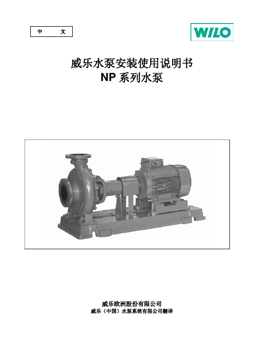
水泵和电机
转速 1450 转/分 转速 2900 转/分
63
64
63
67
65
67
66
70
68
71
70
74
71
75
72
83
73
83
74
84
75
85
76
85
77
85
80
93
80
93
80
93
82
95
83
95
85
95
86
95
86
95
86
96
5 安装 5.1 准备 5.1.1 开箱检查
水泵必须按发货单检查;任何损坏或丢失情况必须立即告知威乐公司。并检查随泵封在一起的备件或 附件的包装。 5.1.2 安装地点
2.4 操作者的安全准则 必须遵守本说明书中的预防事故发生的重要规范。 排除可能引起的电能伤害。必须遵守 VDE 规范(德国电气工程师协会规范)以及当地的电气规程。
2.5 检查和安装的安全规范 操作者有责任确保检查和安装水泵必须由有资质的、授权批准的专业人员进行。 只有在水泵停止运行时,才能进行检修。
在订购配件时,一定要给出水泵和电机所有的技术参数标注在铭牌上。
2 安全准则 此说明书中涵盖了该水泵安装及运行时必需严格遵守的安全准则。因此,安装人员和操作者在安装
和调试水泵前必需认真阅读此说明书。
安全防范部分的安全须知和后面部分中特殊安全标志表示的安全规则都必需认真遵守。在阅读中, 一定要注意安全规范,尤其是一些特殊标志的说明。 2.1 操作说明书中使用的标志说明
2.6 自行改装设备和自制备件 自行改装设备必须经过制造商同意,使用原厂备件将确保安全。使用其他零件,制造商将不承担由
TP型格兰富水泵说明书

安装在水平管里的双头水泵必须在水泵外 壳的上部分安装一个自动排气阀,参见图 5。 自动排气阀不随泵一起供应。 图5
如果液体的温度降低到环境温度以下,水泵 停机后在电机里可能出现冷凝现象。此时, 必须保证电机法兰里的排水孔打开并且向 下,参见图 6。 图6
A: 伸缩接头
B: 混凝土基座
C: 减振器 安装管道时,必须保证水泵外壳不受管道系 统外力影响。 吸水管和放水管的尺寸必须恰当,同时需要 考虑水泵的进口压力因素。 不得将水泵安装在系统的最低点以避免产 生污物沉积。 安装管道要避免气锁现象,特别是水泵进水 侧, 参见图 8。
TP, TPD
安装使用说明书
格兰富使用说明书
责任/远见/创新
一致性声明 我们格兰富公司以独立的责任声明本 声明涉及的产品 TP 和 TPD 符合与欧洲成员 国法律相关的欧洲理事会指令,内容包括: -机械(98/37/EEC) 使用标准:EN ISO 12100 -电磁兼容性(89/336/EEC) 使用标准:EN61 000-6-2 和 EN 61 000-6-3 -特定电压范围内使用的电器设备 (73/23/EEC) [95] 使用标准:EN 60 335-1 和 EN 60 335-2-51
1. 概述 本手册适用于装备有格兰富 MG 和 MMG 型 电机或者 MEZ 63 型电机的 TP 和 TPD 型水 泵。如果水泵安装了其它类型的电机,务必 要注意其电机资料可能会与本说明手册不 同。
功率等于或者大于 4 千瓦电机的水泵应采用 尼龙带和钩环起吊,见图 2。 图2
3. 应用范围 本系列水泵用于下列系统中,进行热水或冷 水循环操作。应用范围涉及家庭、单位和工 业等领域。
7.1 水泵 水泵是免维护的。 如果水泵因为长时间未用而排空,在电机支 架和联轴器之间的轴上注入几滴硅油。这可 以防止轴封面粘连。 7.2 电机 每隔一定时间,电机应该进行检查。确保电 机清洁对保证充分通风非常重要。如果水泵 安装在灰尘很多的环境里,必须定期对水泵 进行清洁和检查。 润滑油: 功率为 11 千瓦以下的电机轴承上添加的润 滑脂可以满足电机整个使用寿命内的需求, 因此不需要润滑油。 功率为 11 千瓦或者以上的电机的轴承必须 根据电机铭牌上的说明加润滑脂。 电机应采用锂基润滑脂进行润滑,润滑脂需 满足下列规格:
污水泵说明书

Flows rates up to:200m 3/hHeads up to:16m Max. immersion:10mMax. particle size:Ø 75 and 100 mm*ND of discharge:80/100 mm*Protection index:IP 68* depending on the modelN.T. N°145-17/ENG. - Ed.1/05-05SUBMERSIBLE PUMPS Lifting of polluted waterCommercial use 4 pole - 50 HzLifting of polluted water in the collective housing, tertiary and industrial sectors. Lifting of:•Wastewater and drainage water •Valve water •Sludgy water•Draining of septic tanks.61411016130200Qm /h3HmAPPLICATIONS•The combination of the two materials Cast iron + 316L Stainless Steel ensures protection against corrosion and increased reliability.•Particle size of up to 100mm.•Two types of standard installation:fixed flooded sump installation and mobile installation.•Possibility of dry well installation with the cooling sleeve’s option.•Possibility of ATEX installation, thanks to the ATEX option and ATEX accessories.•FVO-Cast iron hydraulic part + 316L stainless steel motor.-10 m detachable cable.-Vortex impeller.-Installation on base elbow with Ø 33/42 guide bars or installation on stainless steel legs for a mobile installation.-Available in a version with a cooling sleeve.-Available in an anti-deflagrating version (ATEX).• Hydraulic part -Submersible.- Axial suction under casing, horizontal discharge outlet with flanged fixing.-Intermediate chamber between the pump and the motor, filled with oil, isolated by a fluid side mechanical seal and a motor side lip seal.-A single impeller type: VORTEX.-With a particle size of 75mm for the FVO408s and 100mm for the FVO410s.• Motor-Submersible, direct starting or Y ∆.-Built-in temperature probe protecting the motor against overheating (WSK tempera-ture probe).-Direct starting up to 4 kW; star-delta star-ting beyond this level.-Speed: 1450rpm -Winding:~3; 400V -Frequency:50 Hz -Insulation class:F -Protection index:IP 68-Compliance:CE -Operation:- Continuous S1- Intermittent S3, 20 start/hr recommended-Options :ATEXCooling sleeveModelFVO 408 FVO 410Pump body EN GJL 250EN GJL 250Impeller EN GJL 250EN GJL 250ShaftAISI 420AISI 420Mechanical seal SiC/SiC SiC/SiC Motor side seal NBR NBR Motor frameAISI 316LAISI 316LSTANDARD CONSTRUCTION0048121620HmHft00481216HmHft• FVO 408Mobile installation ND 80TECHNICAL DATAND1ND2A BC D E F G H I J K L M a b c d e k H1N O T 8080200160191498122866030070185355180315200170170220141463585200409Curve Operation Max.P1P2I Speed Mains IP Cable Weight Particle Starting nr starts/h kW kW A RPM voltage m kg size FVO 408-16/2.0T41S120 2.7 2.0 6.114503~400V, 50Hz 68107075directFVO 408-17/2.4T42S120 3.4 2.4 6.714503~400V, 50Hz 68107075direct FVO 408-18/2.7T43S120 3.7 2.77.014503~400V, 50Hz 68107075direct FVO 408-19/3.2T44S120 4.5 3.28.014503~400V, 50Hz 68107075direct FVO 408-21/4.0T45S1205.34.08.914503~400V, 50Hz68107075direct• FVO 410TECHNICAL DATAND1ND2A B C D E F G H I J K L M a b c d e k H1N O T 100100220180181699125582578090195440225400260220220250152089090250450Curver Operation Max.P1P2I Speed Mains IP Cable Weight Particle Starting nr starts/hr kW kW A RPM voltage m kg size FVO 410-20/5.9T46S1207.1 5.914.214503~400V, 50Hz 681096100star-deltaFVO 410-22/7.2T47S1208.87.216.514503~400V, 50Hz 681096100star-delta FVO 410-25/8.4T48S12010.18.418.514503~400V, 50Hz681096100star-deltaMobile installation ND 1002601: Mobile installation base support2: Pipe bend3 & 4: Quick coupling5: Flexible pipe6: Lifting chain•IPAEElectronic Air Pressure Switch for clear and polluted water.-Suitable for operation in an explosive atmosphere.-Useable for draining and filling.-Complies with directive 94/9/CE (ATEX):protection against explosive atmospheres.-Remote control.-Anti-deflagrating.-Insensitive to water temperature and foam.-Acid-resistant.-Undisruptable, highly accurate to within 2cm and economical.-Power supply voltage: 220V -50Hz.-Use with YN 5000E.For an ATEX installation, use the Zener barrier (see IPAE manual for more informa-tion).a) Electrical400V – 50 Hz three-phase direct starting for the FVO 408 model400V – 50 Hz three-phase star-delta starting for the FVO 410 modelMandatory thermal protection againstovercurrents via discontactor, circuit breaker or control unit with level regulator.b) AssemblyPump in a vertical position for fixed or mobile installations.Mobile installation: discharge orificeconnected by an elbow to a flexible pipe of a diameter greater than that of the pump’s discharge.Double installation: the pumps may be twinned via manifold.Check valve and valves to preferably be fitted in the upper part of the discharge duct.Connection via flexible or rigid pipe.c) PackagingPump supplied on a pallet with electric cable H07RN-F (10 m).Screws and fixing for assembling on the base elbow set supplied with the pump.Accessories packaged separately.•Yn4000: control and protection box for 1 or 2 lifting pumps. Management of pump(s) in fixed flooded sump or dry well installations; level monitoring and protecting of motor(s) against overcurrents, overloads and dry running.Control unit order reference Intensity range Yn4100Yn4200in A 1 PUMP 2 PUMPS1.6 to 05 (Yn4105)4035801(Yn4205)40358033.7 to 12 (Yn4112)4035802(Yn4212)4035804Probe management card: 44033562 for S400 (I ≤12A).•YN5000EManagement of one or two pumps by micro-processor in flooded sump or dry well fixed installations. Level monitoring and protecting of motor(s) against overcurrents, thermaloverloads and dry running.•NIVO430Ecological, mercury-free polluted water float switch.Useable for draining and filling, withdiscontactor.Starting intensity rangeREFERENCE A YN 5110E 25212170.5 - 10direct YN 5210E 25212180.5 - 10direct YN 5109E 2521219 6.3 - 9∆Y YN 5209E 2521220 6.3 - 9∆Y YN 5111E 252122110 - 11∆Y YN 5211E 252122210 - 11∆Y YN 5116E 252122312.5 - 16∆Y YN 5216E 252122412.5 - 16∆Y YN 5120E 252122516 - 20∆Y YN 5220E 252122616 - 20∆Y YN 5132E 252122724 - 32∆Y YN 5232E 252122824 - 32∆Y YN 5142E 252122933.1 - 42∆Y YN 5242E 252123033.1 - 42∆Y YN 5155E 252123142.1 - 55∆Y YN 5255E 252123242.1 - 55∆Y YN 5171E 252123371∆Y YN 5271E 252123471∆Y53 bd de la République - Espace Lumière - Bât. 6 - 78403 Chatou Cedex FRANCE Tel: +33 (0)1 30 09 82 39 - Fax: +33 (0)1 30 09 82 34 - 。
水泵操作手册说明书

operation manual23table of contentsIntroduction 4 Using the Operators ManualProduct Identification 5 Water Pump5 EngineSafety 6 Safety Rules6 Hazard Symbols and MeaningsWater Pump Components 11 Component ChartAssembly 12 Connect Suction Hose to Pump12 Attach Suction Hose to Strainer Basket12 Connect Discharge HoseOperation 14 What is “Head”14 Move Water Pump to Safe Location15 Prime the Water Pump16 Locate Strainer Basket Into Water SourceStarting The Water Pump 17 Starting the Water PumpStopping The Water Pump 19 Stopping the Water Pump19 Drain and Flush Water Pump4Using the Operator’s manual The operating manual is an important part of your water pump and should be read thoroughly before initial use, and referred to often to make sure adequate safety and service concerns are being addressed.Reading the owner’s manual thoroughly will help avoid any personal injury or damage to your machine. By knowing how best to operate this machine you will be better positioned to show others who may also operate the unit.This manual contains information for the complete range of BE water pumps, and is placed in order starting from the safety requirements to the operating functions of your machine. You can refer back to the manual at any time to help troubleshoot any specific operating functions, so store it with the machine at all times.Attention: Read through the complete manual prior to the initial use of your water pumpintroduction5product identificationRecord Identification NumbersWater Pump If you need to contact an Authorized Dealer or Customer Service line (1-866-850-6662) for information on servicing, always provide the product model and identification numbers.You will need to locate the model and serial number for the machine and record the information in the places provided below. Date of Purchase:Dealer Name:Dealer Phone:Product Identification NumbersModel Number:Serial Number:EngineHorse Power:6you to hazards. DANGER indicates a hazard which, if not avoided, will result in death or serious injury. WARNING indicates a hazard which, if not avoided, could result in death or serious injury. CAUTION indicates a hazard which, if not avoided, might result in minor or moderate injury. NOTICE indicates a situation that could result in equipment damage.Follow safety messages to avoid or reduce the risk of injury or death.Hazard Symbols and MeaningsSave these InstructionsSafety Rules safetyThis is the safety alert symbol. It is used to alert you to potential personal injury hazards. Obey all safety messages that follow this symbol toavoid possible injury or death.7safety Running engine gives off carbon monoxide, an odorless, 8safety9safety Starter cord kickback (rapid retraction) can result in• NEVER place hands or body parts inside of running pump or hoses.10safety Excessively high operating speeds increase risk of injury and damage 11Read this operator’s manual and safety rules before operating your water pump.water pump components1. Fuel Tank Fill tank with regular unleaded fuel. Always leave room for fuel expansion.2. Priming Plug Fill pump with water here to prime pump before starting.3. Discharge Outlet Connect discharge hose here.4. Choke Lever Prepares a cold engine for starting.5. Air Cleaner Protects engine by filtering dust and debris out of intake air.6. Recoil Starter Used for starting the engine manually.7. Engine Speed Lever Used to adjust engine speed to control pump output.8. On/Off Switch Set this switch to “On” before using recoil starter. Set switch to “Off” to stop a running engine.9. Oil Drain Drain engine oil here.10. Oil Fill Check and add engine oil here.11. Suction Inlet Connect reinforced suction hose here.12. Water Drain Plug Remove to drain water from pump and flush internal components with clean water.13. Pump Chamber Be sure to fill with water before starting.14. Fuel Shutoff Valve Used to turn fuel supply on and off to engine.Item Not Shown:Strainer Basket Used to limit passage of abrasive materials into the pump.1.4.6.8.9.10.11.12.13.14.7.5.2. 3.assemblyYour water pump requires some set up and is ready for use after it has been properly serviced with the recommended oil and fuel.ewdriver.hose with an inside diameter smaller than the pump’s discharge port size.1.Slide barb cuff over hose barb. Insert rubber seal into end of barb cuff as shown earler.2.Screw hose barb assembly onto pump in clockwise rotation until hose barb assembly is tightened securely.assembly discharge port size.1.Slide barb cuff over hose barb. Insert rubber seal into 2.Screw hose barb assembly onto pump in clockwise rotation until hose barb assembly is tightened securely.14What is “Head”Head refers to the height of a column of water that can be delivered by the discharge of the pump.Suction Head is the vertical distance between the center of the pump and the surface of the liquid on the suction side of the pump. May also be referred to as “suction lift”. The atmospheric pressure of 14.7 psi at sea level limits suction head lift to less than approximately 26 feet for any pump.Discharge Head is the vertical distance between the pump’s discharge port and the point of discharge, which is the liquid surface if the hose is submerged or pumping into the bottom of a tank.Total Head is the sum of the suction head value plus the discharge head value.As water pumping height increases, pump output decreases. The length, type, and size of the suction and discharge hoses can also significantly affect pump output. It is important for the suction operation to be the shorter part of the total pumping action. This will decrease the priming time and improve pump performance by increasing the discharge head.Suction head is a maximum of 25 feet and discharge head should be a maximum of 81 feet. Total head can not be more than 106 feet as shown on next page.Move Water Pump to Safe Operating Location For best pump performance, locate the pump on a flat, level surface as close as possible to the water to be pumped. Secure water pump to avoid tipover. Use hoses that are no longer than necessary.IMPORTANT: Direct open end of discharge hose away from home, electrical devices or anything not desired to get wet.operation15Prime the Water Pump 1. Remove priming plug from top of pump.2. Fill pump with clean, clear water up to top of discharge outlet.3. Replace priming plug.operation16Locate Strainer Basket Into Water Source Place strainer basket into water to be pumped. Basket must be fully immersed.operation17Starting the Water Pump Use the following start instructions:1. Make sure unit is on a flat, level surface and pump chamber is primed.2. Turn fuel valve (1) to “On” position. The fuel valve handle will be starting the water pump18IMPORTANT: If excessive fuel is present in the air/fuel mixture causing a “flooded” condition, move choke lever to “Run” position and pull handle repeatedly until engine starts.7. Move choke lever to “Run” position a short distance at a time over several seconds in warm weather or minutes in cold weather. Let engine run smoothly before each change. Operate with choke in “Run” position.IMPORTANT: It may take a few minutes for water pump to begin pumping water.Pump output is controlled by adjusting engine speed. Moving the engine speed lever in the “Fast” direction will increase pump output, and moving the engine speed lever in the “Slow” direction will decrease pump output.starting the water pump19stopping the water pumpStopping the Water Pump 1. Move engine speed lever to “Slow” position.2. Push on/off switch to “Off” position.3. Turn fuel valve to “Off” position.Drain and Flush Water Pump 1. Disconnect and drain suction and discharge hoses.2. Remove drain plug at bottom of pump.3. Remove primer plug from top of pump and flush internal components of pump with clean water.If you need assistance with the assembly or operation of this Water Pump please call 1-866-850-6662。
潜水泵的使用方法

潜水泵的使用方法
潜水泵是一种将液体从低处抽移到高处的泵,通常用于排水、灌溉、排污等场合。
以下是潜水泵的使用方法:
1. 安装:将潜水泵放入液体中,确保泵的进水口完全浸泡在液体中,同时确保电源接头和电源线干燥。
2. 预备:接通电源前,先将泵内的空气排出,可通过泵体上的排气阀或排气孔进行排气操作。
3. 接通电源:根据潜水泵的额定电压和电流要求,将电源线插入电源插座。
4. 启动:启动潜水泵前,确保电源和电线的接触良好,没有松动或接触不良的情况。
按下启动开关或调节调速器,使泵开始工作。
5. 监控:在潜水泵运行期间,要随时关注泵的运行状态,如电流、噪音、振动等。
如发现异常情况,应立即停止泵的运行,并进行排除故障。
6. 停止:使用完毕后,按下停止开关,或将调速器调至最低档位,使潜水泵停止工作。
7. 维护:定期清洗潜水泵的进水口和泵体,防止污物堵塞。
同时检查电源线是否磨损或老化,如果有损坏应及时更换。
需要注意的是,在使用潜水泵时,应根据实际情况选择合适的型号和功率,避免超负荷运行,防止损坏设备。
另外,在操作过程中应注意电源和电器的安全,并遵守相关的安全操作规程。
成都海霖科技有限公司微型泵专用调速器产品说明书

微型泵专用调速器产品说明书文档版本13发布日期2021-03-08版权所有©成都海霖科技有限公司2018。
保留一切权利。
非经本公司书面许可,任何单位和个人不得擅自摘抄、复制本文档内容的部分或全部,并不得以任何形式传播。
商标声明商标为成都海霖科技有限公司的商标。
本文档提及的其他所有商标或注册商标,由各自的所有人拥有。
注意您购买的产品、服务或特性等应受成都海霖科技有限公司相关合同和条款的约束,本文档中描述的全部或部分产品、服务或特性可能未包含在您的购买或使用范围之内。
除非合同另有约定,成都海霖科技有限公司对本文档内容不做任何明示或默示的声明或保证。
由于产品版本升级或其他原因,本文档内容会不定期进行更新。
除非另有约定,本文档仅作为使用指导,本文档中的所有陈述、信息和建议不构成任何明示或暗示的担保。
成都海霖科技有限公司地址:成都市双流区牧华路二段杰邦孵化谷邮编:610000网址:电话:************前言摘要本文为微型泵专用调速器系列产品的相关说明,用于指导相关技术人员初步了解该产品特性。
读者对象本文档适用于负责产品研发的技术人员,您应该非常了解您产品,并对所需微型泵的相关参数、规格大小等信息有明确概念。
关键字调速功能、开放式安装、触控显示器、报警功能修改记录修改记录累积了每次文档更新的说明。
最新版本的文档包含以前所有文档版本的更新内容。
目录前言 (I)修改记录 (II)目录 (III)1产品特性 (1)1.1.调速功能 (1)1.2.开放式安装 (1)1.3.防松螺母 (1)1.4.触控显示器 (1)1.5.保护功能 (2)1.6.报警功能 (2)1.7.数字信号控制 (2)1.8.转速闭环控制 (2)1.9.状态记忆功能 (2)1.10.型号说明 (3)2使用说明 (4)2.1.工作模式说明 (4)2.2.接线与操作说明 (4)2.3.告警与处理 (6)3安装说明 (7)3.1.多功能安装说明 (7)4注意事项 (9)5三维示意图 (10)6产品外观 (11)1产品特性1.1.调速功能与泵配套,可以实现对泵电机转速的调节,从而调节泵的输出流量。
智能液体环流泵LRP 700-1000 VSD+2 产品说明书
LRP 700 – 1000 VSD+ Intelligent Liquid Ring Vacuum PumpA culture of innovationand collaborationAtlas Copco’s culture is one of innovation, continually pushing thelimits of possibility, forging and fostering new ideas and making them reality. We do not develop our products in isolation yet listen intently to our customers to develop truly game changing technologies that suit their real world needs. This customer focused approach is one of the key pillars of our innovation culture and process.New breakthroughs in proven technologyLiquid ring vacuum technology is perfectly suited to wet, humid and dirty applications across many industries. In these applications thepump will face high temperatures, extreme vapor loads and evenliquid and solid carry over from the process. Atlas Copco’s Intelligent liquid ring pumps build on this foundation and through gamechanging innovation take the next step in LRP evolution. We nowintroduce our revolutionary product, the LRP 700-1000 VSD+.The LRP VSD+ is a truly unique liquid ring vacuum pump, offering best in class performance and connectivity. It is a state-of-the-art vacuum2Cleverly engineered ina smart designAtlas Copco’s LRP 700-1000 VSD+ is unique in many ways.The core of the pump is innovative engineering andoptimised design which is then enclosed under a strongcanopy ensuring this pump is as robust as it is beautiful.This sleek look is also ergonomic - HMI, inlet, outlet andmain cable connections are all located at easy to reachpositions on top of the canopy – making this a truly plugand play product.The compact nature of the pump is also striking, havingone of the smallest footprints per unit capacity meansthat the LRP VSDperformance. This tidy unit does not sacrificefunctionality either, included in the pump are a host ofperformance optimising accessories that would normallytake up additional space, piping and installation work.The LRP VSDHaving a noise containing, IP54 rated cubicle, the LRPVSD+ significantly reduces noise pollution and is resistantto dust and water from any direction. Making it ideallysuited for tough applications and environments. Thecanopy follows a wet/dry design principle. The criticalelectronics within the pump are protected from the wetDistinctive compactdesign ~70% spacePlug and play principleInlet – Outlet and mainscable entry at the topIP54 Cubicle with NeosNEMA 4 inverter andMk5 controllerWet/dry conceptNoise containingcanopy ~ 69 dBA34Taking a proven Hick Hargreaves design that already draws on over 150 years of engineering excellence and infusing Atlas Copco innovation has resulted in one of the most intelligent and resilient pumps in the industrial vacuum market today. The LRP 700-1000 VSD + offers optimized performance through VSD + set point control and improved internal geometry. With stainless steel impeller, endplates, liquid reservoir and heat exchanger the LRP 700-1000 VSD + has a high resilience against corrosion and harsh process gases. Along with the robust nature of the pump, the design allows for ease of serviceability when required. Multiple features have been introduced with this in mind, reducing the amount of time needed to service the pump to an absolute minimum.• Horizontal serviceability, no need to position the pump vertically • No oil, no regular filter exchange • Mechanical seals – eliminate leaking gland sealing • Lantern flange arrangement – automatic alignment of the motor • Removable heat exchanger with flexible piping for continued operation • Ease of cleaning the vessel by convenient access portA heritage of reliability and resilienceVacuum DemandEnergy ConsumptionTimeVacuum DemandEnergy ConsumptionFixed speed vacuum pumpVacuum Demand Energy ConsumptionTimeVacuum DemandVSD + energy consumption5A Liquid Ring Pump in absolute harmony using twin VSDVSD for set point controlVSD for water controlOur LRP 700-1000 VSD + has not one VSD, but two! The first VSD is for the vacuum set point control to maintain and match required vacuum levels. This allows you to optimize your energy consumption by accurately maintaining the required vacuum level to suit your process. The minimum required flow is maintained by altering the motor speed as needed. With no wastage, you optimize your process efficiency and performance. LRP 700-1000 VSD + delivers exactly to the process demand and consumes only for what is required. It is the perfect vacuum arrangement.The second VSD regulates the water circulation pump optimizing water flow and maintaining stable vacuum levels throughout the operating range and pump running speeds. Coupled with the integrated inlet spray nozzles, the inverter driven circulation pump safeguards the LRP 700-1000 VSD + performance even at lower inlet pressures.A patented algorithm to balance the operation of the water pump with the speed of the main motor brings a harmony between the twin VSD. Guaranteeing that the pump is always in a state of optimal performance and bringing maximum energy efficiency for our customers.The Automatic Seizure Prevention algorithmsafeguards the LRP 700-1000 VSD + by preventing the pumping element from seizure after a prolonged period of inactivity. The result - maximized lifetime and reduced maintenance requirements.Smart monitoring andremote controllabilityElektronikon®The Atlas Copco MkV Elektronikon® controller is a standard feature of the LRP VSD+ series. Elektronikon® is a state-of-the-art monitoring system for your vacuum pumps. It is user friendly, comprehensive and powerful. It can also integrate your plant management system for full pump and therefore vacuum process control.The Elektronikon® also provides market leading feedback on the status of yourLRP 700-1000 VSD+ including pump operating status, set point control and inlet conditions to name a few. Access all of the information for everyday managementof your vacuum pump such as warning alarms, safety shutdowns andmaintenance information.ES Central ControllersAtlas Copco’s ES central controllers allow you to monitor and control multiple LRP VSD+ vacuum pumps simultaneously. Thanks to smart control, the ES gives you the most suitable product performance mix at all times. This maximizes energy savings using set-point control and by mapping equal running hours across multipleinstalled pumps, keeping servicing requirementsto a minimum. The ES controller also allowsyou to run your vacuum net within anarrow, predefined pressure band. Thisincreases the stability of the processand optimizes overall energyconsumption.E S vc o nn e ct i v it y67SMART LINK; central + are connected to pumps is enormous.Process OutletLiquid Fill Over owLiquid Fill Valve Separator Cooler Inlet Cooler Outlet CoolerGas & LiquidLiquid8An energy-efficient, reliable and robust mode of operationThe LRP VSD + series is the most energy efficient solution for applications with a high vapor load. The closed loop water circuit withintegrated heat exchanger ensures the sealant water exiting the pump discharge is collected in the seal liquid reservoir and recirculated. The gained heat load is removed by passing through the stainless-steel heat exchanger contained within the LRP 700-1000 VSD +. All water level monitoring and top-up is a fully automated standard feature of the LRP VSD +. No more worrying about whether your pump will run out of water or when, with our total recovery mode of operation you can expect improved performance, maximised energy savings and reduced water costs.9Suited for wet and humid applicationsseries is ideally suited for humid, wet andTechnical specificationsLRP 700 VSD+LRP 900 VSD+LRP 1000 VSD+ Nominal capacity Dry-m3/h (m3/h)7409401050Dry-cfm436553618Saturated-m3/h91010901140Saturated-cfm536642671 Ultimate pressure(Absolute) mbar25inch Hg0.7Nominal installed motor kW18.52637hp24.834.949.6 Footprint mm1950 x 810 x 1020(WxDxH)inch76,8 x 31,9 x 40,2Inlet/ Outlet EN1092-1/01/B1/DN100/PN10 Connection Liquid fill/ Manual drain G 1/2" BSP(F)Overflow G 1" BSP(F)6996 0066 00 © 2019, A t l a s C o p c o . A l l r i g h t s r e s e r v e d . D e s i g n s a n d s p e c i fi c a t i o n s a r e s u b j e c t t o c h a n g e w i t h o u t n o t i c e o r o b l i g a t i o n . R e a d a l l s a f e t y i n s t r u c t i o n s i n t h e m a /vacuum。
格兰富常用水泵服务手册
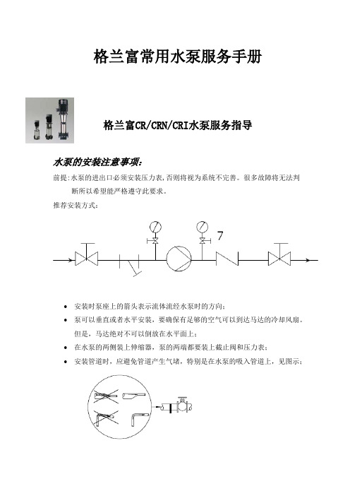
格兰富常用水泵服务手册格兰富CR/CRN/CRI水泵服务指导水泵的安装注意事项:前提:水泵的进出口必须安装压力表,否则将视为系统不完善。
很多故障将无法判断所以希望能严格遵守此要求。
推荐安装方式:•安装时泵座上的箭头表示流体流经水泵时的方向;•泵可以垂直或者水平安装,要确保有足够的空气可以到达马达的冷却风扇。
但是,马达绝对不可以倒放在水平面上;•在水泵的两侧装上伸缩器,泵的两端都要装上截止阀和压力表;•安装管道时,应避免管道产生气堵,特别是在水泵的吸入管道上,见图示;•安装时如果有下列情况,必须在水泵附近安装一个真空阀:排出管总是从泵开始向下倾斜;存在虹吸管影响的危险;有必要防止不干净的液体回流;•请在对水泵和管路进行连接之前,确认已经对管路进行了必要的清洗。
切记不能用水泵来冲洗管道,不能在水泵安装好进出管路后,再进行管路焊接等,主要是避免可疑物或焊渣等进入水泵内;•安装完后,如果不使用,用挡物盖住水泵,避免水和其他异物进入风扇及接线盒内;•如果水泵室外安装,强烈建议水泵电机安装防雨蓬;•如果水泵为变频控制,强烈建议对1.5KW 以下的电机加装LC滤波器,对于其它功率的电机,也建议加装滤波器。
在水泵未充满液体和彻底排空气之前,不要启动水泵。
水泵的调试(含注意事项):前提:确定水电已经到位!•关闭排出口的截止阀,完全打开吸入口的截止阀;•取出泵顶端的灌液塞,给水泵缓慢地灌液,灌好后重新安装回灌液塞并拧紧;•打开排气阀给水泵排气,同时稍微打开排出口的截止阀;•启动水泵并检查转向,马达的风扇上标有水泵的正确转向;•继续排气,同时把排出口侧的截止阀开的更大一些;•当排气阀流出的液体稳定后,关闭排气阀,并打排出口侧的截止阀;•调整水泵工作曲线在额定扬程和流量(参考水泵铭牌);•确认水泵运行电流和电压,保护设置最大不能超过电机额定电流;•详细记录并归档保存。
严禁闭阀运行,最小流量至少应为最大流量的10% 。
泵的铭牌上标有泵的流量和扬程水泵常见故障及排除:序号常见故障排除方案1 电机反转更换任意2相电源线的相序2 水泵有噪音a)气蚀噪音(调整出口阀门,水泵噪音会减少),出口压力表是否有抖动?如有,要排气。
泵宝中文说明书
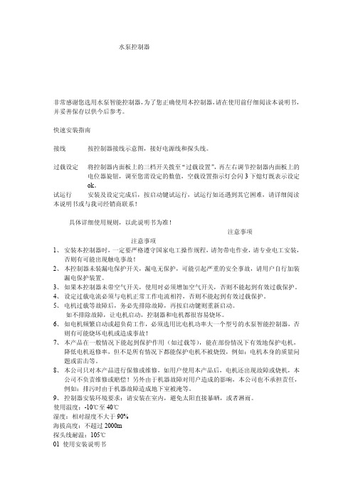
水泵控制器非常感谢您选用水泵智能控制器,为了您正确使用本控制器,请在使用前仔细阅读本说明书,并妥善保存以供今后参考。
快速安装指南接线按控制器接线示意图,接好电源线和探头线。
过载设定将控制器内面板上的三档开关拨至“过载设置”,再左右调节控制器内面板上的电位器旋钮,调至您需设定的数值,空载设置指示灯会闪3下熄灯既表示设定ok。
试运行安装及设定完成后,按启动键试运行,试运行如还遇到其它困难,请详细阅读本说明书或与我司经销商联系!具体详细使用规则,以此说明书为准!注意事项注意事项1、安装本控制器时,一定要严格遵守国家电工操作规程,请勿带电作业,请专业电工安装,否则有可能出现触电事故!2、本控制器未装漏电保护开关,漏电无保护,可能引起严重的安全事故,请用户自行加装漏电保护装置。
3、如果本控制器未带空气开关,使用时必须增加空气开关,否则不能起到有效过载保护。
4、设定过载电流必须与电机正常工作电流相符,否则不能起到有效过载保护。
5、电机过载等故障后,务必先排除故障,再按启动键则重新启动。
如不排除故障,让电机启动,控制器和电机都很容易烧坏。
6、如电机频繁启动或超负荷工作,必须选用比电机功率大一个型号的水泵智能控制器,否则有可能烧坏电机或造成事故!7、本产品在一般情况下能起到保护作用(如过载等),能在部份情况下有效地保护电机,降低电机返修率,但不是所有情况下都能保护电机不被烧毁,例如:电机本身的质量问题或雷击等。
8、本公司只对本产品进行保修或维修,如用户使用本产品后,电机还出现故障或烧机,本公司不负责维修或赔偿!另外由于机器故障对用户造成的影响,本公司也不承担责任,例如:排污时由于机器故障造成地下室被淹等。
9、控制器安装环境要求:请安装在室内,避免太阳直接暴晒,或者淋雨。
使用温度:-10℃至40℃湿度:相对湿度不大于90%海拔高度:不超过2000m探头线耐温:105℃01 使用安装说明书一、产品包装水泵智能控制器说明书探头安装螺丝及胶塞1台1本1套各3个二、产品特点♦采用数码芯片控制,集上、下液位和压力自动控制于一体♦具有自动、手动两种工作模式可供选择♦具有过载、空载、超低压等保护功能♦具有空载重启时间1~240分钟可调♦具有故障记忆功能,5次故障原因可能轻易查阅♦专利交流数码讯号检测功能,探头更耐用♦安装方面,调试简单三、主要技术参数1、静态功率小于3.5W,动态功率小于4.5W;2、出厂默认值:A.过载设定默认值为:1.5KW为8A,2..2KW为11A;B.空载设定值为00.0A,空载保护后自动恢复时间为30分钟;3、最大控制距离:500米;4、过载保护反延时特性,时间误差为±15%:过载倍数 1.2倍 1.5倍2倍3倍5倍保护时间 50秒30秒15秒6秒1秒四、安装接线指南1、将控制器固定在墙壁上,打开接线盒,按标签提示接好电源、水泵。
海利普变频器恒压供水说明书

1
其它功能
海利普变频器
散热片过热保护、反转限制、开机后直接起动、故障复归、参数锁 定 PID、一拖多等。
批示灯显示项目说明
显示项目 PA00.0 Pb00.0 c00.00 F00.00 T00.00 A000.0 00000 u000.0 u000.0 00000 L000.0
指示灯状态¤亮 HZ A R/min
200 休眠使能 0 - 1 说明: 0 禁止 1 允许
201 开始休眠判断频率 0 - 50.00 出厂值:0 说明:单泵工作时,变频器输出频率低于此参数时,经休眠启动延时后,停机
202 休眠启动延时 0 – 4min
出厂值:0
说明:单泵工作时,变频器输出频率低于开始休眠判断频率设定的值,此功能起用;
说明:0.电阻压力传感器; 1.(4 - 20ma)电流压力传感器; 2.( 0-10V)电压压力传感器;
181 传感器量程 0 – 3 出厂值: 说明:00 - 2.5 Pa 01 - 5.0 Pa 02 - 7.5 Pa 03 - 10.0 Pa
182 传感器校零 0 – 10 出厂值: 说明:对传感器量程的零位置校正
194 加泵延时时间 0 - 99 30 单位:秒 出厂值:20s
说明:系统在此设定时间到达后检测当前压力值,压力值小于设定值时完成加泵操作;
195 减泵延时时间 0 - 99 10 单位:秒 出厂值:30s
说明:系统在此设定时间到达后检测当前压力值,压力值大于设定值时完成加泵操作;
196 泵切换偏差 0 - 20%
CD240 CD241
功能 参数锁定 恢复出厂值 端子功能选择 定时运行时段选择 #1 时段起始时间 #1 时段状态选择 #2 时段起始时间 #2 时段状态选择 #3 时段起始时间 #3 时段状态选择 #4 时段起始时间 #4 时段状态选择 #5 时段起始时间 #5 时段状态选择 #6 时段起始时间 #6 时段状态选择 #7 时段起始时间 #7 时段状态选择 #8 时段起始时间 #8 时段状态选择 #9 时段起始时间 #9 时段状态选择 #10 时段起始时间 #10 时段状态选择 #11 时段起始时间 #11 时段状态选择 #12 时段起始时间 #12 时段状态选择
潜水污水泵产品说明说明书
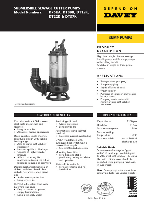
P R O D U C TD E S C R I P T I O NHigh head single channel sewage handling submersible sump pumps with cutting impeller.Available in single or three phase motors.A P P L I C AT I O N S•Sewage water pumping •Sump emptying•Septic effluent disposal •Water transfer•Pumping of light soft slurries and factory waste•Pumping waste water with stringy or long soft solids in suspensionO P E R AT I N G L I M I T S F E AT U R E S & B E N E F I T SCorrosion resistant 304 stainless steel shaft, motor shell and fasteners•Long service life•Attractive, lasting appearance Open impeller, single channel,centrifugal design with cutting leading edge•Able to pump soft solids in suspension•Less susceptible to blockage •Capable of higher heads /pressure•Able to cut string likematerials, reducing the risk of blockage in pump or pipework Double mechanical shaft seal in oil bath with hard faced silicon carbide / ceramic seal on pump side•Added motor protection •Long service lifeHO7RNF oil resistant leads with bare wire lead ends•Easy to connect to power supply terminations •Long life in dirty waterSand slinger lip seal •Added protection •Long service lifeAutomatic resetting thermal overload•Protected against overloading D75KA model fitted with automatic float switch with a present float length•Safe unattended operation Mounting base fitted •For a firm and stablepositioning during installation and operation Slide rail kits available•For easy removal and re-installationCapacities to 1100lpm Heads to24.5m Max. submergence 25m Max. operating temperature 50o CMax. soft solidsup to 80% of discharge sizeSuitable FluidsSemi-screened sewage or “grey water” of neutral pH containing up to 20% small soft solids or 1% string like solids. Some wear should be expected while pumping hard solids in suspension.Note: Cutter pumps are not suitable forsanitary products - use Grinder models.SUMP PUMPS60Hz models available.Cutter Type ‘K’ SeriesM AT E R I A L S O F C O N S T R U C T I O NPA R TM AT E R I A LImpeller Cutting tip Diffuser plate Pump casing OutletShaft seal pump sidemotor sideShaft seal elastomer Pump shaft OringsMotor shell Handle FastenersFloat & power supply leadsCast ironTungsten carbide Hardened cast iron Cast iron Cast ironSilicon carbide/ceramic Carbon/ceramic Mechanical seals in captive oil bath with oil sealNitrile rubber 304 stainless steel Nitrile rubber 304 stainless steel 304 stainless steel 304 stainless steel HO7RN-F oil resistantE L E C T R I C A L D ATAI N S TA L L AT I O N & P R I M I N GCommon to all modelsSpeed2 pole, 2850rpmInsulation class Class F IP ratingX8Electrical lead H07RNF x 10m lengthUse a rope to position and retrieve the pump. Do not lower or retrieve the pump using the power lead as this may damage the cable entry seals, causing water leaks and unsafe operation.Don’t use this product for recirculating or filtering swimming pools, spas, etc. While these pumps are built to high safety standards, they are not approved for installations where people will be in the water while they are operating.Don’t pump abrasive materials. Sand and grit in the water being pumped will accelerate wear, causing shortened pump life.Keep your pump clean, particularly in situations where lint, hair or fibrous materials may get bound around the pump shaft. Regular inspection and cleaning will extend pump life.Make room for the float switch to operate. Automatic models have a float switch to turn them on when the water level rises and turn them off again when it has been pumped down to the safe operating level of the pump. If the float switch is not free to rise and fall, correct pump operation may not be possible.Don’t run your pump dry. Non-automatic models must be switched off manually or by way of an external float/level switch when the water level is reduced to the top of the pump housing.00510152025l/min ft m g/min 0110220330FLOWTOTAL HEAD1020304050607080D I M E N S I O N SDavey Products Pty LtdMember of the GUD Holdings Ltd GroupABN 18 066 327 517Head Office and Manufacturing 6 Lakeview Drive,Scoresby, Australia 3179Ph:+61 3 9730 9222Fax:+61 3 9753 4100Website:.au Customer Service Centre Ph:1300 367 866Fax:1300 369 119E-mail:***************.au Interstate OfficesSydney - Brisbane - Adelaide Perth - TownsvilleInternational 6 Lakeview Drive,Scoresby, Australia 3179Ph:+61 3 9730 9121Fax:+61 3 9753 4248E-mail:****************.au GermanyKantstrasse 47,04275 Leipzig Ph:+49 341 301 0412Fax:+49 341 301 0413E-mail:**********************New Zealand 2 Rothwell Avenue,North Harbour, Auckland 1330Ph:+64 9 914 3680Fax:+64 9 914 3685Website: E-mail:****************.nz USADavey Pumps Inc.1005 N. Commons Drive Aurora, Illinois 60504Ph:+1 630 898 6976Fax:+1 630 851 7744Website: E-mail:******************This literature is not a complete guide to product usage. Further information is available from your Davey dealer, Davey Customer Service Centre and from the relevant product Installation and Operating Instructions. This data sheet must be read in conjunction with the relevant product Installation and Operating Instructions and all applicable statutory requirements. Product specifications may change without notice.® Davey is a registered trademark of Davey Products Pty Ltd. © Davey Products Pty Ltd 2000.DPM139-1/5K/0205/GPW supersedes DPM139/3K/0802/GPWD75KA DT08K Supply voltage 220-240V 380-415V 50Hz - Phase Single Three Output power 0.75kW 0.75kW Full load current 7.5A 1.5A Locked rotor current 22.5A 10.5A StartingCSIR DOLDT15K DT22K DT37KSupply voltage 380-415V 380-415V 380-415V 50Hz - Phase Three Three Three Output power 1.5kW 2.2kW 3.7kW Full load current 3.0A 4.5A 7.0A Locked rotor current22A 31.5A 49A Starting DOLDOL DOL。
格拜卢普公司316不锈钢浸湿泵数据手册说明书

A GORMAN-RUPP COMPANY316 Stainless Steel Submersible Pumps⏹Flows from 300 to 5,200 GPM⏹Heads to 1,400 FT⏹Horsepowers: 10 to 500 HP⏹6” – 12” motor brackets, 2 and 4 pole⏹Temperatures to 158° F (70° C)EX Series8” – 16” Curves andTechnical Manual50010001500U.S. GALLONS PER MINUTEHeadtoFeetComposite Performance CurveA GORMAN-RUPP COMPANYEX Series 8” – 16” Curves and Technical ManualA GORMAN-RUPP COMPANY| Identificación bombaMinimum well diameter in inchesDiámetro interior mínimo del pozo en pulgadasPump type (mixed-flow) Bomba tipo (semiaxial)Stainless steel executionFabricación inoxidableHydraulic size Dimensión hidráulicaNumber of stages Número de etapas Impeller size Tamaño rodetesMotor external diameter in inches Diámetro exterior de motor en pulgadasNominal power in HP Potencia nominal en CVFrequency 60Hz Frecuencia de 60HzList of parts and materials | Detalle partes y materialesCampos de utilización8EXMax. water temperatureTemperatura máx. agua bombeada2A GORMAN-RUPP COMPANY8EX1Performances at 60Hz, 2 poles | Prestaciones a 60Hz, 2 polos60HzSubmersible PumpsQ=H e a d - A l t u r aH =A GORMAN-RUPP COMPANYPerformances at 60Hz, 2 poles | Prestaciones a 60Hz, 2 polos60Hz8EX2Submersible Pumps4A GORMAN-RUPP COMPANYPerformances at 60Hz, 2 poles | Prestaciones a 60Hz, 2 polos60HzQ=H e a d - A l t u r aH =8EX3Submersible PumpsA GORMAN-RUPP COMPANYPerformances at 60Hz, 2 poles | Prestaciones a 60Hz, 2 polos60HzQ=H e a d - A l t u r aH =8EX4Submersible PumpsA GORMAN-RUPP COMPANY| Identificación bombaMinimum well diameter in inchesDiámetro interior mínimo del pozo en pulgadasPump type (mixed-flow)Bomba tipo (semiaxial)Stainless steel executionFabricación inoxidable. max. capacityCaudal máxima al B.E.P.Number of stagesNúmero de etapasImpeller sizeTamaño rodetesMotor external diameter in inchesDiámetro exterior de motor en pulgadasNominal power in HPPotencia nominal en CVFrequency 60HzFrecuencia de 60HzCampos de utilizaciónMax. water temperatureTemperatura máx. agua bombeada8EX-110-8EX-1406A GORMAN-RUPP COMPANY7Performances at 60Hz, 2 poles | Prestaciones a 60Hz, 2 polos60HzQ=H e a d - A l t u r aH =8EX-110Submersible Pumps8A GORMAN-RUPP COMPANYPerformances at 60Hz, 2 poles | Prestaciones a 60Hz, 2 polos60HzQ=H e a d - A l t u r aH =Submersible Pumps8EX-140A GORMAN-RUPP COMPANY9| Identificación bombaMinimum well diameter in inches Diámetro interior mínimo del pozo en pulgadasPump type (mixed-flow)Bomba tipo (semiaxial)Stainless steel executionFabricación inoxidableHydraulic size Dimensión hidráulicaNumber of stages Número de etapas Impeller size Tamaño rodetesMotor external diameter in inches Diámetro exterior de motor en pulgadasNominal power in HP Potencia nominal en CVFrequency 60Hz Frecuencia de 60HzList of parts and materials | Detalle partes y materialesCampos de utilización10EXMax. water temperature Temperatura máx. agua bombeada10A GORMAN-RUPP COMPANYPerformances at 60Hz, 2 poles | Prestaciones a 60Hz, 2 polos60HzEff %m H mQ=Capacity CaudalH e a d - A l t u r aH =H ftSubmersible Pumps10EX1Pump supplied with NPTF companion flange, boltsand gasketLa bomba se suministra con contrabrida, pernos y juntaA GORMAN-RUPP COMPANYPerformances at 60Hz, 2 poles | Prestaciones a 60Hz, 2 polos60HzQ=H e a d - A l t u r aH =Submersible Pumps10EX212A GORMAN-RUPP COMPANYPerformances at 60Hz, 2 poles | Prestaciones a 60Hz, 2 polos60HzQ=H e a d - A l t u r aH =Submersible Pumps10EX3A GORMAN-RUPP COMPANY| Identificación bombaMinimum well diameter in inchesDiámetro interior mínimo del pozo en pulgadasPump type (mixed-flow) Bomba tipo (semiaxial)Stainless steel executionFabricación inoxidable . max. capacity Caudal máxima al B.E.P .Number of stages Número de etapas Impeller size Tamaño rodetesMotor external diameter in inches Diámetro exterior de motor en pulgadasNominal power in HP Potencia nominal en CVFrequency 60Hz Frecuencia de 60HzCampos de utilizaciónMax. water temperatureTemperatura máx. agua bombeada10EX-30014A GORMAN-RUPP COMPANYPerformances at 60Hz, 2 poles | Prestaciones a 60Hz, 2 polos60HzQ=H e a d - A l t u r aH =10EX-300Submersible PumpsA GORMAN-RUPP COMPANYPerformance range | Campos de utilización 12”12EX16A GORMAN-RUPP COMPANYPerformances at 60Hz, 2 poles | Prestaciones a 60Hz, 2 polos60HzQ=H e a d - A l t u r aH =12EX3Submersible PumpsA GORMAN-RUPP COMPANYPerformances at 60Hz, 2 poles | Prestaciones a 60Hz, 2 polos60HzQ=H e a d - A l t u r aH =12EX4Submersible Pumps18A GORMAN-RUPP COMPANY14”Performance range | Campos de utilización14EXA GORMAN-RUPP COMPANYPerformances at 60Hz, 2 poles | Prestaciones a 60Hz, 2 polos60HzQ=H e a d - A l t u r aH =14EX-650Submersible Pumps20A GORMAN-RUPP COMPANY16”Performance range | Campos de utilización16EXPerformances at 50Hz, 2 poles | Prestaciones a 50Hz, 2 polos50HzQ=H e a d - A l t u r aH =16EX-1000Submersible PumpsA GORMAN-RUPP COMPANYARIZONA (Main Office)7706 N. 71st Ave., Glendale, AZ 85303-1703 (623) 979-3560 • Fax (623) 979-2177 (800) 966-5240FLORIDA195 E. 3rd Street, Zolfo Springs, FL 33890(863) 735-8222 • Fax (863) 735-8202(800) 994-3045MISSISSIPPI11176 Green Valley Dr., Olive Branch, MS 38654(662) 895-1110 • Fax (662) 895-5083(866) 668-4914A GORMAN-RUPP COMPANYProud member of American Petroleum Institute and these organizations:Creating Quality Pump Systems and Satisfied Customers。
翡菲科高流高性能水泵说明书
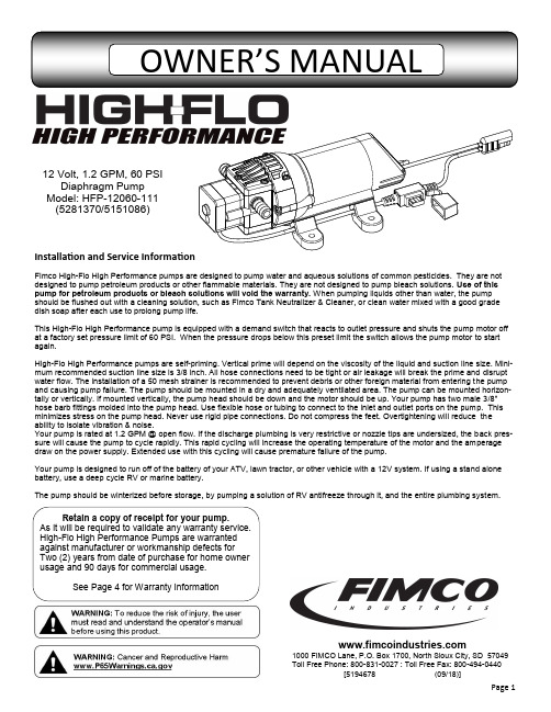
1000 FIMCO Lane, P.O. Box 1700, North Sioux City, SD 57049 Toll Free Phone: 800-831-0027 : Toll Free Fax: 800-494-0440[5194678 (09/18)]Installation and Service InformationFimco High -Flo High Performance pumps are designed to pump water and aqueous solutions of common pesticides. They are not designed to pump petroleum products or other flammable materials. They are not designed to pump bleach solutions. Use of this pump for petroleum products or bleach solutions will void the warranty. When pumping liquids other than water, the pump should be flushed out with a cleaning solution, such as Fimco Tank Neutralizer & Cleaner, or clean water mixed with a good grade dish soap after each use to prolong pump life.This High -Flo High Performance pump is equipped with a demand switch that reacts to outlet pressure and shuts the pump motor off at a factory set pressure limit of 60 PSI. When the pressure drops below this preset limit the switch allows the pump motor to start again.High -Flo High Performance pumps are self -priming. Vertical prime will depend on the viscosity of the liquid and suction line size. Mini-mum recommended suction line size is 3/8 inch. All hose connections need to be tight or air leakage will break the prime and disrupt water flow. The installation of a 50 mesh strainer is recommended to prevent debris or other foreign material from entering the pump and causing pump failure. The pump should be mounted in a dry and adequately ventilated area. The pump can be mounted horizon-tally or vertically. If mounted vertically, the pump head should be down and the motor should be up. Your pump has two male 3/8” hose barb fittings molded into the pump head. Use flexible hose or tubing to connect to the inlet and outlet ports on the pump. This minimizes stress on the pump head. Never use rigid pipe connections. Do not compress the feet. Overtightening will reduce the ability to isolate vibration & noise.sure will cause the pump to cycle rapidly. This rapid cycling will increase the operating temperature of the motor and the amperage draw on the power supply. Extended use with this cycling will cause premature failure of the pump.Your pump is designed to run off of the battery of your ATV, lawn tractor, or other vehicle with a 12V system. If using a stand alone battery, use a deep cycle RV or marine battery.The pump should be winterized before storage, by pumping a solution of RV antifreeze through it, and the entire plumbing system.12 Volt, 1.2 GPM, 60 PSIDiaphragm Pump Model: HFP -12060-111 (5281370/5151086)Retain a copy of receipt for your pump.As it will be required to validate any warranty service. High -Flo High Performance Pumps are warranted against manufacturer or workmanship defects for Two (2) years from date of purchase for home owner usage and 90 days for commercial usage.See Page 4 for Warranty InformationDO∙ Clean and rinse your pump after each use with Fimco TankNeutralizer∙ Winterize your pump or sprayer by rinsing, draining andrunning RV Antifreeze through it before storing for the winter. ∙ Use clean water for your spray mixture ∙ Store inside a building when not in use.DON’T∙ Use to pump bleach.∙ Use to pump petroleum products such as diesel fuel,gasoline or kerosene∙ Leave your pump sit with spray mixture in it for extendedperiods∙ Use dirty or unfiltered water for sprayingTroubleshooting the Pump:Motor does not run:∙ Check for loose wiring connection(s).∙ Make sure the 'ON/OFF' switch in the lead wire assemblyis in the 'ON' position. "I" is the 'ON' position and 'O' is the 'OFF' position.∙ Check for defective pressure switch. Make sure you areconnected to a good 12 volt power source. Make sure any on/off switches are in the 'on' position. Remove the cap to the pressure switch. Pull both red wires off of their terminals, and touch the two ends together. If your pump runs when you do this, your pressure switch will need to be replaced. ∙ Check the fuse.∙ Check for low voltage at the power supply.Pump does not prime:∙ Check for air leaks in supply line.∙ Check for debris in the check valve assembly. ∙ Check for defective check valve. ∙ Check for clogged strainer/filter.∙ Check for cracks in the pump housing. ∙ Check for empty product supply.Low Pressure/Low Flow:∙ Check for leaks in the discharge line. ∙ Check for restriction in the discharge line. ∙ Check for debris in nozzle orifice. ∙ Check for clogged strainer.∙ Check for proper voltage—try another 12-volt battery.Pulsating flow (surging):∙ Low flow may cause pump to surge.∙ Spray wand is adjusted for a small or fine spray pat-tern.∙ Slightly open bypass (if applicable) to overcome.∙ If needed, pressure switch may need to be adjusted—adjust a quarter turn at a time clockwise until surging stops.∙ Check for defective pressure switch. ∙ Check for leaks in the discharge line. ∙ Check for restriction in the discharge line. ∙ Check for debris in nozzle orifice. ∙ Discharge hose may be too long. ∙ Check for clogged strainer.Motor continues to run after discharge is shut off: ∙ Check for empty product supply.∙ Check for open bypass valve. (if equipped) ∙ Check for low voltage.∙ Check for leak in discharge line. ∙ Check for defective pressure switch. ∙ System has leaks.Fuse blows:∙ Excessive voltage.∙ Improper adjustment of pressure switch. ∙ Damaged or defective wiring harness. ∙ Half -moon & counterweight are sticking. ∙ Defective pressure switch.Motor runs, but no pressure:CHECK:Both the counterweight and the bearing need to spin freely and both need to spin INDEPENDENTLY of each other. If these 2 pieces are ‘stuck’ together, you will need to break them free and whether or not they are sticking, spray some good quality lubricant or something similar on them and let it soak in and this should restore most of your prime.Checking the Pressure Switch :If your motor is not running and you’ve checked the following: for loose wiring connections, fuse, the switch on the lead wire was “ON” and made sure you were connected to a fully charged battery and everything is fine, but the motor won’t run, then it’s time to check to see if the pressure switch is bad.∙ Remove the cover off the 1” square box (pressure switch) on the head ofthe pump, the cover is held on by one phillips -head screw. This will expose the two red wires.∙ With the pump connected to a good 12 volt power source and everythingon.∙ Slip the two red wires off the terminals and touch them together.If the motor runs, it means the pressure switch is bad and needs to be replaced. If it still doesn’t run, try bypassing the switch in the lead wire or using another lead wire. Even if a tester shows power to the pressure switch, it still could be the switch in the wire that is causing the problem.If still not responsive, use a voltmeter or electrical tester to make sure you are getting power to the head of the pump, as it could possibly be something in one of the wires or even the lead wire assembly may need to be replaced.Warning: It is NOT recommended to run the pump this way, as the pump will continue to run and not shut off.This could result in blown hoses when all discharges are closed. Also, this could result in premature failure of the pump completely.WarrantyLIMITED WARRANTY FOR NEW FIMCO EQUIPMENTWHO MAY USE THIS LIMITED WARRANTY. This limited warranty (the “Limited Warranty”) is provided by Fimco to the original purchaser (“you”) of the Equipment (as defined below) from Fimco or one of Fimco’s authorized dealers. This Limited Warranty does not apply to any subsequent owner or other transferee of the Equipment. THIS LIMITED WARRANTY GIVES YOU SPECIFIC LEGAL RIGHTS, AND YOU MAY ALSO HAVE OTHER RIGHTS WHICH VARY FROM STATE TO STATE.WHAT THIS LIMITED WARRANTY COVERS AND FOR HOW LONG. Fimco warrants that any new Equipment will be free from defects in material and workmanship for a period of two (2) years (homeowner), 90 days (commercial user), after delivery of the Equipment to you (the “Warranty Period”). The Warranty Period is not extended if Fimco repairs or replaces the Equipment.WHAT IS NOT COVERED BY THIS LIMITED WARRANTY. This Limited Warranty does not apply to: (1) used Equipment; (2) any Equipment that has been altered, changed, repaired or treated since its delivery to you, other than by Fimco or its authorized dealers; (3) damage or depreciation due to normal wear and tear; (4) defects or damage due to failure to follow Fimco’s operator’s manual, specifications or other written instructions, or improper storage, operation, maintenance, application or installation of parts; (5) defects or damage due to misuse, accident or neglect, “acts of God” or other events beyond Fimco’s reasonable control; (6) accessories, attachments, tools or parts that were not manufactured by Fimco, whether or not sold or operated with the Equipment; or (7) rubber parts, such as tires, hoses and grommets.HOW TO OBTAIN WARRANTY SERVICE. To obtain warranty service under this Limited Warranty, you must (1) provide written notice to Fimco of the defect during the Warranty Period and within thirty (30) days after the defect becomes apparent or the repair becomes necessary, at the following address: Fimco, 1000 FImco Lane, North Sioux City, SD 57049; and (2) make the Equipment available to Fimco or an authorized dealer within a reasonable period of time. For more information about this Limited Warranty, please call: 800-831-0027WHAT REMEDIES ARE AVAILABLE UNDER THIS LIMITED WARRANTY. If the conditions set forth above are fulfilled and the Equipment or any part thereof is found to be defective, Fimco shall, at its own cost, and at its option, either repair or replace the defective Equipment or part. Fimco will pay for shipping and handling fees to return the repaired or replacement Equipment or part to you.LIMITATION OF IMPLIED WARRANTIES AND OTHER REMEDIES. THE REMEDIES DESCRIBED ABOVE ARE YOUR SOLE AND EXCLUSIVE REMEDIES, AND FIMCO’S SOLE LIABILITY, FOR ANY BREACH OF THIS LIMITED WARRANTY. TO THE EXTENT APPLICABLE, ANY IMPLIED WARRANTIES, INCLUD-ING, WITHOUT LIMITATION, THE IMPLIED WARRANTIES OF MERCHANTABILITY AND FITNESS FOR A PARTICULAR PURPOSE, SHALL BE LIMITED IN DURATION TO THE WARRANTY PERIOD, AND THE REMEDIES AVAILABLE FOR BREACH THEREOF SHALL BE LIMITED TO THE REMEDIES AVAILABLE UNDER THIS EXPRESS LIMITED WARRANTY. SOME STATES DO NOT ALLOW LIMITATIONS ON HOW LONG AN IMPLIED WARRANTY LASTS, SO THE ABOVE LIMITATION MAY NOT APPLY TO YOU. IN NO EVENT SHALL FIMCO’S LIABILITY UNDER THIS LIMITED WARRANTY EXCEED THE ACTUAL AMOUNT PAID BY YOU FOR THE DEFECTIVE EQUIPMENT, NOR SHALL FIMCO BE LIABLE, UNDER ANY CIRCUMSTANCES, FOR ANY CONSEQUENTIAL, INCIDENTAL, SPECIAL OR PUNITIVE DAMAGES OR LOSSES, WHETHER DIRECT OR INDIRECT. SOME STATES DO NOT ALLOW THE EXCLUSION OR LIMITATION OF INCIDENTAL OR CONSEQUENTIAL DAMAGES, SO THE ABOVE LIMITATION OR EXCLUSION MAY NOT APPLY TO YOU.。
潮流北美漂浮池水泵系统操作说明及零件手册说明书
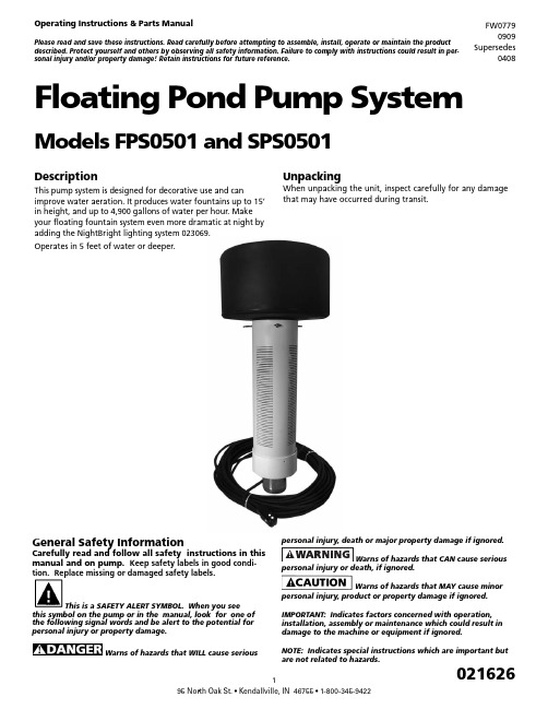
DescriptionThis pump system is designed for decorative use and canimprove water aeration. It produces water fountains up to 15’ in height, and up to 4,900 gallons of water per hour. Make your floating fountain system even more dramatic at night by adding the NightBright lighting system 023069.Operates in 5 feet of water or deeper.UnpackingWhen unpacking the unit, inspect carefully for any damage that may have occurred during transit.Floating Pond Pump SystemModels FPS0501 and SPS0501Operating Instructions & Parts ManualPlease read and save these instructions. Read carefully before attempting to assemble, install, operate or maintain the product described. Protect yourself and others by observing all safety information. Failure to comply with instructions could result in per-sonal injury and/or property damage! Retain instructions for future reference.FW07790909 Supersedes0408General Safety InformationCarefully read and follow all safety instructions in this manual and on pump. Keep safety labels in good condi-tion. Replace missing or damaged safety labels.This is a SAFETY ALERT SYMBOL. When you seethis symbol on the pump or in the manual, look for one of the following signal words and be alert to the potential for personal injury or property damage.Warns of hazards that WILL cause seriouspersonal injury or death, if ignored.Warns of hazards that MAY cause minorpersonal injury, product or property damage if ignored.IMPORTANT: Indicates factors concerned with operation, installation, assembly or maintenance which could result in damage to the machine or equipment if ignored.NOTE: Indicates special instructions which are important but are not related to hazards.Never enter the watereither wading, swimming or in a boat with thepump power on, as this may result in severecarefully. Failure to follow could result in serious bodilyinjury and/or property damage.shall be in accordance with National ElectricCode (NEC) and all applicable local codesand ordinances. A licensed electrician shouldperform installation.“NO SWIMMING” ANDOR WARNING SIGNS SHOULD BE POSTED PERSTATE AND LOCAL CODES.Please affix included warning label to powerreceptacle or junction box.100ft power cord with three prong GFI plug. –Must connect to properly grounded receptacleof grounding type. Do not remove groundpin on plug. Do not extend the cord length by splicing orTHIS UNIT, WITH THE GFI, TO A PROPERLYGROUNDED RECEPTACLE MAY RESULT INto a circuit equipped with a fuse or circuitbreaker of ample capacity.Always disconnect powersource before performing any work on ornear the motor or its connected load. If thepower disconnect point is out-of-sight, lock itin the open position and/or tag it to prevent unexpectedapplication of power. Failure to do so could result in fatalelectrical shock or bodily injury.DO NOT handle pump withwet hands or when standing in water asfatal electrical shock could occur. Disconnectmain power supply before handling systemfor any reason.from coming in contact with sharp objects,oil, grease, hot surfaces or chemicals. DONOT kink the power cable. If damagedbox, fused disconnect switch, or covers open(either partially or completely) when notbeing worked on by a competent electricianor repairman.Always use caution whenoperating electrical controls in damp areas.If possible, avoid all contact with electricalequipment during thunderstorms or extremedamp conditions.equipment in protected area to preventmechanical damage which could produce seriouselectrical shock and/or equipment failure.DO NOT use this system topump flammable liquids such as gasoline, fueloil, kerosene, etc. Failure to follow the abovewarning could result in property damage and/or personal injury.Do not pump water above 120 degreesFahrenheit.Water leaving nozzle is at high velocityand can cause bodily injury if contact is made.in swimming pool areas.!to the State of California to cause cancer and birth defects orother reproductive harm.!coming out the bottom and protected from direct rainfall.INSTALLATION INSTRUCTIONS1. Only install this system in ponds where no swimming,wading, boating or fishing is allowed while fountain isoperating. Disconnect power to pump before fishing orentering the water.2. Post appropriate warning signs per local and state codes.3. Inspect pump system for damage before installing inpond. Check that all bolts and screws are tight. Check forany bent prongs or a cracked case on the GFI.4. The unit ships with one spray nozzle attached. To changeto one of the other 2 nozzles, remove the 4 screws fromthe nozzle then replace with desired nozzle. Refer toFigures 1, 2 & 3 for spray pattern appearance. Nozzlesare marked “This side up.” Make sure the o-ring isseated in groove before installing nozzle. Tighten screwsuntil seated, approximately 10 to 12 in-lbs.5. Attach nylon anchor ropes to 3 eyebolts located at topof screen. Secure (make sure rope is tight) to weightsplaced on pond floor or stakes on pond shore. Whenusing weights to anchor the pump, place weightsapproximately 10 feet from unit. Alternately, two anchorropes placed 180 degrees apart can be used, but 3 ropeswill provide the best stability.6. Before connecting the unit to the power receptacle,check to insure there is no leakage to ground. This canbe done by using an ohm meter and setting the scale toits highest setting (i.e. Rx100K). Connect one ohmmeter lead to the unit power cord ground (round prong) and to one of the flat prongs. It should read infinite or at least 2 mega ohms. Repeat with the other prong. If reading is below 2 mega ohms on either prong contact Customer Service Help Line listed at bottom of page.7. Do Not Operate System on an Extension Cord. If no power is accessible at the pond, contract a licensed electrician to install the proper power supply in accordance with National Electric Code and all applicable local codes and ordinances.8. After installing the unit, checking ground andconnecting power to the unit, the unit can be powered up. Check operation of the GFI by pushing the “Test” button, the unit should stop. Pushing the “Reset” button should restart the unit. If pressing the “test” button does not stop the unit, immediately shut off power to unit and contact Customer Service Help Line listed at bottom of page.NOZZLE PATTERNST h is s id eu p Figure 1: Water Lily - An eye-catching combination spray. Item #2AT h i s s id eu pFigure 2: Sky Cannon - A dramatic single plume of water. Item #2BT h i s s id eu pFigure 3: Water Trumpet - A symmetrical inverted bell shape.Item #2CFigure 4: Typical InstallationINSTALLATION CHECK LIST☐ Read installation instructions and warnings ☐ Post appropriate warning signs ☐ Install desired spray nozzle ☐ Install and anchor unit in pond☐ Check insulation resistance to ground ☐ Power up unit☐ Test operation of GFI by pressing the “Test” Button.☐ File instructions for future reference REQUIRED TOOLS & SUPPLIES• #2 Phillips screwdriver • Nylon rope to anchor unit• Stakes or weights for anchoring unit• Ohm meter to check insulation resistance to groundWINTER STORAGE• Rinse unit with clean water to remove any build-up on unit.• Check unit for any damage.• Store unit in heated space in freezing climates.The pump motor is water lubricated and is factory filledwith an antifreeze solution. During operation the antifreeze may exchange, thru the filtered check valve, with the pond water. In climates where freezing may occur, the unit must be stored in a heated storage space to prevent damage to the motor.TROUBLESHOOTING GUIDE PROBLEM POSSIBLECAUSESCORRECTIVE ACTIONUnit won’t run Circuit break-er trippedReset circuit breaker GFI Tripped Reset GFINo or low spray Blockedscreen ornozzle, miss-ing or dam-aged o-ring,or incorrectlyinstallednozzleDisconnect power. Clean screenand/or nozzle. Check that o-ring isundamaged and seated in groove.Check that nozzle is installed prop-erly (nozzles are marked “This sideup”). Check depth of pond. If lessthan 5 feet deep, move to deepersection. Restart unit.GFI Trips Electricalstorm can tripGFIReset GFIShort in sys-tem Disconnect power and check cord for damage. If cord is damaged contact Customer Service Help Line listed at bottom of page for replacement.Unit spins Anchor ropeloose Check anchor rope and re-attach if necessaryItem #Qty Part No.Description16021624Screw - #10 x 3/4 Pan Head High-Low 2A1021617Nozzle - Water Lily2B1021618Nozzle - Sky Cannon2C1021619Nozzle - Water Trumpet31021622O-Ring - AS568A - 041 (3” ID x 3/18” OD) 44021628Bolt - SS 1/4-20 x 3/454021629Lockwasher - 1/4”61021707Mounting Flange71021534Float81021713Pump End91021740Motor 1/2 HP 115V104127021Locknut - SS 5/16-24111021715100 ft. power cord with GFI11A1021614GFI123021609Eye Bolt - SS 1/4-20 x 2-1/2133021623Locknut - SS 1/4--20141021608Screen151021611Screen Cap161021613Strain Relief172021625Warning DecalFlow (GPH)Spray Height(Ft.)PatternImagePatternName 490015Thissi de upIL053Thissi de upThissi de upWater Lily- 2A 330015Sky Cannon- 2B 270013WaterTrumpet - 2C15161112(A/B/C)345671710911131214811A。
清洁冷水农业用途Engine Monoset水泵产品指南说明书

PRODUCT MANUAL FORENGINE MONOSET PUMPS FOR CLEAR, COLDWATER FOR AGRICULTURAL PURPOSESACCORDING TO IS 11501:2023This Product Manual shall be used as reference material by all Regional/Branch Offices & licensees to ensure coherence of practice and transparency in operation of certification under Scheme-I of Bureau of Indian Standards (Conformity Assessment) Regulations, 2018 for various products. The document may also be used by prospective applicants desirous of obtaining BIS certification licence/certificate.BUREAU OF INDIAN STANDARDSManak Bhawan, 9, Bahadur Shah Zafar Marg,New Delhi – 110002ANNEX AList of Test Equipment Major test equipment required to test as per the Indian StandardANNEX BScheme of Inspection And Testing1. LABORATORY - A laboratory shall be maintained which shall be suitably equipped (as per the requirement given in column 2 of Table 1) and staffed, where different tests given in the specification shall be carried out in accordance with the methods given in the specification.1.1 The manufacturer shall prepare a calibration plan for the test equipments.2. TEST RECORDS – The manufacturer shall maintain test records for the tests carried out to establish conformity.3. LABELLING AND MARKING– As per the requirement of IS 11501:2023. The Standard Mark, as given in the Schedule of the licence, shall be marked on each Engine Monoset Pump provided always that the product thus marked conforms to all the requirement of the specification. In addition, the licence no. CM/L-__________ and details of BIS website shall be marked at an appropriate place on product or package as follows: “For details of BIS certification please visit .in”4. CONTROL UNIT –All pumps of same input, manufactured under essentially similar conditions, in a fortnight shall constitute a control unit.5. LEVELS OF CONTROL - The tests as indicated in column 1 of Table 1 and the levels of control in Column 3 of Table 1, shall be carried out on the whole production of the factory which is covered by this plan and appropriate records maintained in accordance with paragraph 2 above.5.1All the production which conforms to the Indian Standards and covered by the licence should be marked with Standard Mark.6. REJECTIONS –Disposal of non-conforming product shall be done in such a way so as to ensure that there is no violation of provisions of BIS Act, 2016.Note-1: Sub-contracting is permitted to a laboratory recognized by the Bureau or Government laboratories empanelled by the Bureau.Note-2: The control unit and levels of control as decided by the Bureau are only recommendatory in nature. Manufacturer may define his own Batch No./Control Unit/levels of control and implement with approval of Head (BO).4Scope of Licence5。
- 1、下载文档前请自行甄别文档内容的完整性,平台不提供额外的编辑、内容补充、找答案等附加服务。
- 2、"仅部分预览"的文档,不可在线预览部分如存在完整性等问题,可反馈申请退款(可完整预览的文档不适用该条件!)。
- 3、如文档侵犯您的权益,请联系客服反馈,我们会尽快为您处理(人工客服工作时间:9:00-18:30)。
greenpro水泵说明书
浙江威格泵业有限公司成立于2008年,是专业从事热水循环泵设计、开发、生产的制造企业,位于温岭市大溪镇,占地面积2500㎡,建筑面积9000㎡,年销售量达80万台。
公司已获得“温岭市百强企业”、“重点工业企业”、“出口优胜企业”等荣誉。
公司主要生产EA、RS、GR系列热水循环泵,产品畅销欧盟、美国、南美洲。
是以产品出口为主的外向型企业,并获得国家技术监督局颁发的生产许可。
企业拥有自营进出口权,获得CQC、CE、GS、REACH、ROHS、ERP等认。
主要生产家用型自动增压泵,所生产的屏蔽式自动增压泵、屏蔽式循环泵系列采用耐热180度漆包线、也是国内少数几家有屏蔽泵测试设备的企业,其测试性能参数值达到欧洲标准并得到CE认、屏蔽式热水循环泵年出口量在50万台,而且每年在递增、已经成为同行业中的佼佼者.......
产品特点:
超低噪音,水泵噪音的声强级低于(欧共体(EEC)机械设备标准).
屏蔽式原理,无油封、无泄漏、使用寿命长,维护简单
安装前要仔细阅读说明书,拍下前需要联系卖家,因为卖家为实体店,避免断货发货不及时给您带来不便。
水泵属于机电类产品,不能走航空运输,路途较远的地方时间会较长,推荐您选择近些的卖家去购买。
包装破损请您拒收,如签收了我们无法追究运快递输造的责任。
关于产品购买说明
1:如需开具的客户请您联系客服,普通另加5%,增值税另加8%;
2:关于运输,发货前都已经检查测试并打好包装,签收时候请确认包裹完整无破损变形(包装破损变形的请拒收);
3:关于退货换货:产品支持7天包退,退货原则为不影响卖家二次销售(不能安装使用,包装完好。
我们发货给您一台临时安装使用过的水泵您也是不同意的);
4:关于责任承担:买家自己选择的水泵型号能否达到自己要求由买家承担责任;卖家推荐型号及参数由买家确认是否可用,如果卖家发货的产品与推荐型号参数不符,卖家承担责任;
5:关于退货运费:我们已经为客户购买了运费险,一般退货都由运费险赔付,退货所产生的额外运费由责任方负担;
6:关于质保:格兰富家用水泵质保期24个月,其它品牌质保期12个月,特殊说明质保期的按说明为准;。