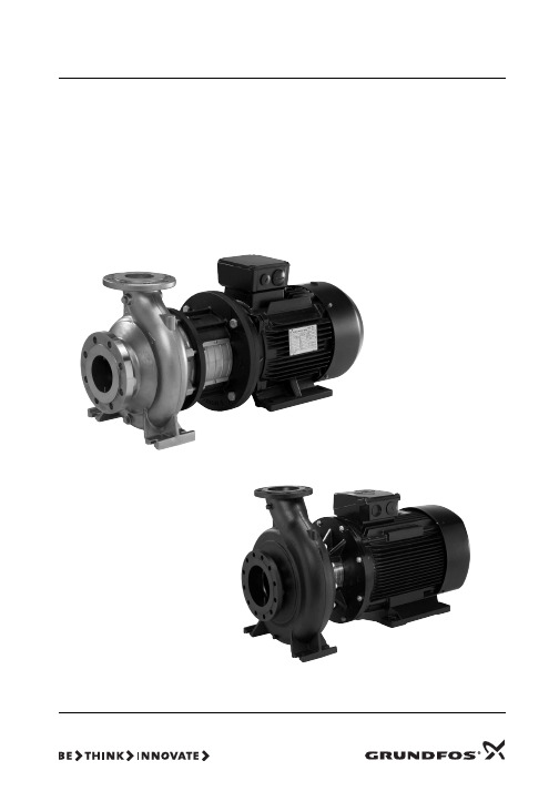
格兰富DDA计量泵使用说明书
格兰富水泵自带变频器操作说明书R操作

页
开始安装之前,务必认真阅读本安装与使用说明书,
3
特别要仔细阅读随同产品一起发运的标准水泵的安装
3
3
和使用说明,泵的安装和使用还要符合当地法规的要求。
4
4
1. 综述
4
4
格兰富的 E 泵是配有频率控制的标准单相或者三相马达的
4
水泵。
4
水泵带有内置的 PI 控制器,可以连接到外部的传感器上,能够
4
控制系统的瞬时压力、压差、温度、温差或者流量。水泵也可以设定
要使用外部的启动/停止输入。 当泵接通电源后,泵将在大约 5 秒钟内启动。
2.2.5 过电压保护 水泵本身带有内置的变阻器,对线电压之间和线-地电压
间的过电压进行保护。
5
2.3 其它连接
图8
图 7、图 8、图 9 所示为外部无源触点的接线端子,这些端
子用于连接启动/停止和数字功能、外部设定值信号、传感器信
IEC364 的规定,这种电源开关的每一极的触点距离至 少为 3mm。 2.2.2 触电保护—间接接触
2.2.6 电源电压 3×380-415V±10%,50/60Hz,PE 泵的铭牌上标出了电源的电压和频率,请确保马达适用于
所提供的电源。 水泵接线盒内的电线应尽可能地短,但地线除外。当无意
间拉断电缆时,地线应是最后被拉掉的,因此地线必须保证有足 够的长度。
所用标准:EN292 — 电磁兼容性(89/336/EEC)
所用标准:EN61 800-3 — 在一定电压范围内使用的电气设备(73/23/EEC)
所用标准:EN 60 335-1 和 EN 60 335-2-51. Bjerringbro , 2001 年 1 月 1 日
格兰富高压水泵说明书
重量: 见包装箱上的标签。
警告 泵配电机4 kw以上配有吊装环,但此吊装环不能用来 起吊整个泵。 见图4。 应使用尼龙带和扣环或吊钩来吊装水泵,如图1到3所示。
图 3 不带电机水泵的正确吊装
TM05 3309 1112
TM03 3972 1306
TM03 3973 1306
96145329
青铜/黄铜
1.4301/1.4308
C EN-GJL-250
EN-GJL-200
青铜/黄铜
1.4401/1.4408
D EN-GJL-250
青铜 CuSn10
青铜/黄铜
1.4401/1.4408
E EN-GJL-250
EN-GJL-200
EN-GJL-250
9. 法兰受力与力矩
10. 电气连接 10.1 电机保护 10.2 变频器操作
11. 试运行和启动 11.1 概述 11.2 试运行 11.3 启动注水 11.4 检查旋转方向 11.5 启动 11.6 轴封磨合期 11.7 起动与停止次数 11.8 监控设备的参考读数
12. 12.1 12.2 12.3 12.4
2
Model B 96126252 P2 0612 0001
3
Q 23.4 m3/h H 22.6 m n 2900 min-1 p/t 16/120 bar/°CMAX 0(, 0.70 Șp 68.8 % 6
4
Made in Hungary
5
78
9
图 5 NB 泵铭牌示例
图例
位置号
1 2 3 4 5 6 7 8 9
Standards used: EN 809:1998 + A1:2009. — ATEX Directive (94/9/EC).
格兰富水泵自带变频器操作说明书 R100操作
13
13
13
13
14 有关安装详情,请参见标准水泵的安装与使用说明
15
15
16
16
16
16
16
16
16
16
17
17
2.1 电气连接—单相泵 注:用户或者安装人员要保证水泵得以按照现行有效的国际和当 地标准安装正确的接地和保护,所有工作必须由有资格的电气人 员来进行。
实际的电源电路连接参见图 3
图3
综述 双头泵 安装 电气连接—单相泵 电源开关 触电保护—间接触点 附加保护 马达保护 过电压保护 供电电压 泵的启动/停止 电气连接—三相泵 电源开关 触电保护—间接触点 附加保护 马达保护 过电压保护 电源电压 泵的启动/停止 其它连接 信号电缆 泵的设定 工厂设定 通过控制面板进行设定 设定值设定 设定为最大工作曲线 设定为最小工作曲线 泵的启动/停止 通过 R100 进行设定 运行菜单 设定值的设定 运行模式设定 故障指示 警报记录 状态菜单 实际设定值显示 运行模式显示 实际值显示 实际速度显示 输入功率和功耗显示 运行时间显示 安装菜单 选择控制模式 控制器的设定 选定外部设定值信号 选择故障、运行和待命信号继电器 锁定水泵上的按钮 水泵编码 选择数字输入功能 传感器设定 设定最小和最大工作曲线 外部强制控制信号 启动/停止输入 数字输入 外部设定值信号 总线信号 设定的优先级 指示灯和信号继电器 绝缘测量 技术数据—单相泵 电源电压 漏电电流 输入/输出 技术数据—三相泵 电源电压 漏电电流 输入/输出 其它技术数据 废物处理
2.1.3 附加保护 如果水泵所连接的电力系统带有附加的对地漏电断路器保
护,则该断路器必须用以下符号进行标记。
2.1.7 泵的启动/停止 由电源执行的启动和停止次数每小时不得超过 4 次。 如果需要更多的启动和停止次数,则启动/停止水泵时,需
计量泵操作说明书1
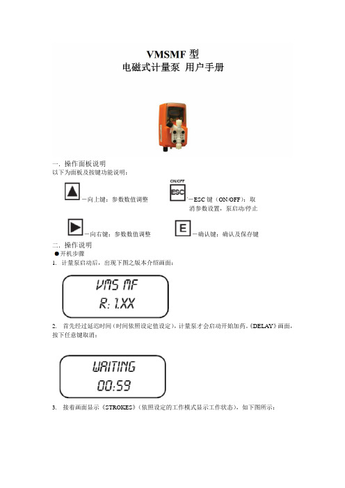
以下为面板及按键功能说明:消参数设置,泵启动/停止二.操作说明1.计量泵启动后,出现下图之版本介绍画面:2. 首先经过延迟时间(时间依照设定值设定),计量泵才会启动开始加药。
《DELAY》画面,按下任意键取消:3. 接着画面显示《STROKES》(依照设定的工作模式显示工作状态),如下图所示:启动/停止计量泵《ESC》键有两个功能,一是取消及放弃参数设置功能;二是作为计量泵的启动/关闭功能。
计量泵于《OFF》状态时,无法进入功能设置页面进行参数设置,如下图所示,按住《ESC》键(约3秒钟)启动计量泵;任何时间或任何设置页面按住《ESC》键(约3秒)可停止计量泵。
(OFF-停止,ON-启动)动作模式设置MODE-PROG[1]VMS MF型计量泵可工作于七种不同模式,分别为:CONSTANT/定量式、DIVIDE/脉冲分配式、MULTIPL Y/脉冲乘算式、PPM/百分比浓度控制式、BATCH/批量式、VOLT/电压控制式、mA/电流控制式。
我们的计量泵都是脉冲输出信号所以只需设置两个参数就可以实现计量泵的加药动作。
MULTIPLY/脉冲乘算式-MOD[03]接收脉冲水表或其他脉冲讯号来源,计量泵以倍数进行加药动作。
倍数最小值为1,错误的数值计量泵将不会储存。
若觉得加药太慢可以适当的增加倍数。
按《向上/向右》键修改参数值,按《E》键储存设置,按《ESC》键放弃修改或离开。
同时设置《DELAY TIME》(讯号周期时间),计量泵将自动把动作间隔平均分散于下一个脉冲讯号之前,请参考初始设置说明《DELAY-SET[05]》。
设置SETUP-PROG[2]除了动作模式设置之外,另外有参数需进行设置,由《MODE-PROG[2]》选单进入。
TIMEOUT/脉冲间隔时间-SET[05]此设置仅对《MULTIPL Y》(脉冲乘算式)动作模式有效。
当计量泵接收到水表的讯号后就开始动作,动作时间为第一个脉冲至下一个脉冲的时间段。
格兰富卧式水泵安装和操作说明书
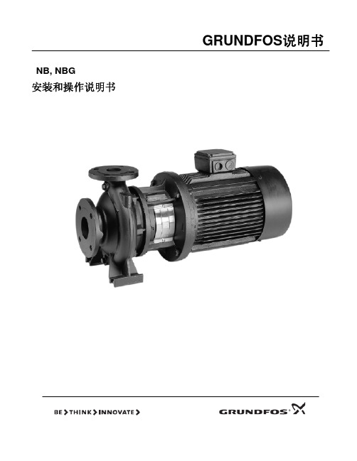
GRUNDFOS说明书NB, NBG安装和操作说明书目录页1. 一般信息 22. 交付和吊装 22.1 交付 22.2 吊装 23. 型号标示说明 33.1 NB 型 3 3.2 NBG 型 3 3.3 叶轮直径 5 3.4 泵的工作液体54. 技术数据 54.1 环境温度 54.2 液体温度 54.3 工作压力 5 4.4 最低入口压力 5 4.5 最高入口压力 54.6 最小流量 5 4.7 最大流量 54.8 电气数据 54.9 重量 54.10 噪音等级 5 4.11 泵的转速与材料尺寸的关系 55. 不含电机的泵 65.1 不带支脚的电机 65.2 带支脚的电机 86. 安装 10 6.1 安装前的准备 106.2 泵的位置 10 6.3 连接 106.4 基础 116.5 阻尼减振 11 6.5.1 软连接 12 6.5.2 阻尼减振器 12 6.6 直接连接管路 126.7 管路安装 126.8 旁路 12 6.9 测量仪器 137. 法兰受力与扭矩 138. 电气连接 14 8.1 电机保护 14 8.2 变频器的操作 14 9. 启动 149.1 一般信息 149.2 排气 14 9.3 检查转动方向 159.4 启动 15 9.5 起动/停车 1510. 维护 1510.1 泵 15 10.2 轴的机械密封 1510.3 电机 15 10.4 润滑 15 10.4.1 轴承润滑脂 15 11. 停泵期间的霜冻保护 15 12. 服务 1512.1 维修用成套备件 15 13. 最小入口压力的计算 1614. 故障检查表 1715. 处理 18在开始安装之前,应该仔细阅览设备的安装与工作说明书。
设备的安装与使用,也应该与本条例一致,并遵从良好的操作规范。
1. 一般信息泵的名称和型号标注在泵的铭牌上。
泵装有格兰富的MG 型或MMG 型电机。
如果泵所配的电机是 格兰富 以外的其他类型,请注意电机数据是否与本手册中所列数据有差异。
格兰富 Medium UPM 泵产品说明书
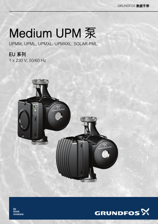
GRUNDFOS 数据手册Medium UPM泵UPMM, UPML, UPMXL, UPMXXL, SOLAR PMLEU系列1 x 230 V, 50/60 Hz目录2Medium UPM?1.概述3Medium UPM泵 - EU系列. . . . . . . . . . . . . . . . . . . . . . . . . . . . . . . . . . . . . . . . . . . . . . . . . . . . . . . . . . . . . . . . . . . . . . . 3应用 . . . . . . . . . . . . . . . . . . . . . . . . . . . . . . . . . . . . . . . . . . . . . . . . . . . . . . . . . . . . . . . . . . . . . . . . . . . . . . . . . . . . . . . . 3安全指导. . . . . . . . . . . . . . . . . . . . . . . . . . . . . . . . . . . . . . . . . . . . . . . . . . . . . . . . . . . . . . . . . . . . . . . . . . . . . . . . . . . . . 52.特点与优点6特点 . . . . . . . . . . . . . . . . . . . . . . . . . . . . . . . . . . . . . . . . . . . . . . . . . . . . . . . . . . . . . . . . . . . . . . . . . . . . . . . . . . . . . . . . 6优点 . . . . . . . . . . . . . . . . . . . . . . . . . . . . . . . . . . . . . . . . . . . . . . . . . . . . . . . . . . . . . . . . . . . . . . . . . . . . . . . . . . . . . . . . 6 ERP,生态设计规范. . . . . . . . . . . . . . . . . . . . . . . . . . . . . . . . . . . . . . . . . . . . . . . . . . . . . . . . . . . . . . . . . . . . . . . . . . . . 6标识 . . . . . . . . . . . . . . . . . . . . . . . . . . . . . . . . . . . . . . . . . . . . . . . . . . . . . . . . . . . . . . . . . . . . . . . . . . . . . . . . . . . . . . . . 73.性能概览84.产品范围95.控制模式和信号10控制原理. . . . . . . . . . . . . . . . . . . . . . . . . . . . . . . . . . . . . . . . . . . . . . . . . . . . . . . . . . . . . . . . . . . . . . . . . . . . . . . . . . . . 106.控制模式、用户界面和设置13供暖系统中的泵控制. . . . . . . . . . . . . . . . . . . . . . . . . . . . . . . . . . . . . . . . . . . . . . . . . . . . . . . . . . . . . . . . . . . . . . . . . . . 13控制模式说明. . . . . . . . . . . . . . . . . . . . . . . . . . . . . . . . . . . . . . . . . . . . . . . . . . . . . . . . . . . . . . . . . . . . . . . . . . . . . . . . 13用户界面. . . . . . . . . . . . . . . . . . . . . . . . . . . . . . . . . . . . . . . . . . . . . . . . . . . . . . . . . . . . . . . . . . . . . . . . . . . . . . . . . . . . 18 7.技术描述19爆炸图 . . . . . . . . . . . . . . . . . . . . . . . . . . . . . . . . . . . . . . . . . . . . . . . . . . . . . . . . . . . . . . . . . . . . . . . . . . . . . . . . . . . . . 19剖面观 . . . . . . . . . . . . . . . . . . . . . . . . . . . . . . . . . . . . . . . . . . . . . . . . . . . . . . . . . . . . . . . . . . . . . . . . . . . . . . . . . . . . . 20材料规格. . . . . . . . . . . . . . . . . . . . . . . . . . . . . . . . . . . . . . . . . . . . . . . . . . . . . . . . . . . . . . . . . . . . . . . . . . . . . . . . . . . . 20部件说明. . . . . . . . . . . . . . . . . . . . . . . . . . . . . . . . . . . . . . . . . . . . . . . . . . . . . . . . . . . . . . . . . . . . . . . . . . . . . . . . . . . . 21 8.安装尺寸23泵送液体. . . . . . . . . . . . . . . . . . . . . . . . . . . . . . . . . . . . . . . . . . . . . . . . . . . . . . . . . . . . . . . . . . . . . . . . . . . . . . . . . . . . 23机械安装. . . . . . . . . . . . . . . . . . . . . . . . . . . . . . . . . . . . . . . . . . . . . . . . . . . . . . . . . . . . . . . . . . . . . . . . . . . . . . . . . . . . 24电气安装. . . . . . . . . . . . . . . . . . . . . . . . . . . . . . . . . . . . . . . . . . . . . . . . . . . . . . . . . . . . . . . . . . . . . . . . . . . . . . . . . . . . 26 9.启动3110.维修3211.产品处置3412.性能曲线35曲线条件. . . . . . . . . . . . . . . . . . . . . . . . . . . . . . . . . . . . . . . . . . . . . . . . . . . . . . . . . . . . . . . . . . . . . . . . . . . . . . . . . . . . 3513.数据表3614.附件4515.批准和认证46EC产品合格声明书 . . . . . . . . . . . . . . . . . . . . . . . . . . . . . . . . . . . . . . . . . . . . . . . . . . . . . . . . . . . . . . . . . . . . . . . . . . . 46 VDE证书 . . . . . . . . . . . . . . . . . . . . . . . . . . . . . . . . . . . . . . . . . . . . . . . . . . . . . . . . . . . . . . . . . . . . . . . . . . . . . . . . . . . 47对某些不能使用的化学物质,格兰富提供产品化学符合声明. . . . . . . . . . . . . . . . . . . . . . . . . . . . . . . . . . . . . . . . . . . . 47 REACH法规(EC 1907/2006). . . . . . . . . . . . . . . . . . . . . . . . . . . . . . . . . . . . . . . . . . . . . . . . . . . . . . . . . . . . . . . . . . 47有关REACH、RoHS和其他相关化学品法规以及格兰富产品化学品合规性计划的客户信息. . . . . . . . . . . . . . . . . . . . 47 WEEE指令2012/19/EU. . . . . . . . . . . . . . . . . . . . . . . . . . . . . . . . . . . . . . . . . . . . . . . . . . . . . . . . . . . . . . . . . . . . . . . . 48 16.缩写493不同的管路可以安装不同版本的Medium UPM循环泵。
格兰富说明书
开电源,以启动或停用水泵。 ·图 B:显示通过外部转接接触,连接或断
开电源,以启动或停用水泵。
5.2 带继电器模块的双头水泵 水泵具有在三种速度下工作的过载保护装 置,因此水泵可直接与主电源连接。 水泵在工厂设置时就具有在工作水泵和备用 水泵之间切换的功能。每 24 小时切换一次。 本说明书末尾的图 C 到 E 显示了可能的连接 和在不同操作方法下的选择开关的设置。 ·图 C:交替操作 ·图 D:备用操作,水泵 1 作为工作水泵,
水泵操作时要求的最小入口压力见 118 页。 声压标准
水泵声压应低于 70dB(A)
输入与输出 标准模块
热控过载开关 (接线头 T1/T2)
电压:250V AC 电流:
Cosϕ =1.0:2.5A Cosϕ =0.6:1.6A
继电器模块
启动/停止输入 (接线头 7 和 8)
操作/故障指示输出 (接线头 1 到 3)
泵,另一个持续作为备用水泵。
3. 单水泵操作:水泵可以互相独立操作。
5
4. 安装
水泵的安装位置必须避免人员意 外接触水泵炽热的表面。
安装水泵时,凸缘带有卵圆形螺栓孔的 UPS (D)32-xx, 40-xx, 50-xx, 60-xx 型水泵及其 垫片需按图 3 操作:
图3 安装
双头水泵接线盒的可能位置见图 6。
60Hz 3x200-230V 50/60Hz
备用保险丝
最大 10A 封闭等级
IP 44 环境温度
0℃~40℃ 相对空气湿度
最大 95% 液体温度
连续:-10℃~+120℃ 短期可达+140℃
格兰富水泵技术资料GB安装使用说明书
GB 安装使用说明书
合格声明
我们格兰富公司对本声明唯一负责任, 本声明涉及的 Hydro2000 E 产品符合欧洲经济共同体(EEC:European Economic Community)成员国的规定,该成员国相似法律作如下规定: — 机械制造(89/392/EEC)
所用标准:EN292 — 电磁兼容(89/336/EEC)
8. 维 护
8.1 增压设备的维护 8.1.1 泵 8.1.2 电机轴承 8.1.3 霜冻保护 8.2 Control 2000 E 的维护
9. 运行和故障指示 10. 故障查找表 11. 技术数据
11.1 水力数据 11.2 工作条件 11.3 声压级 11.4 电气数据
12. 术语汇编 13. 显示概观
⎯ 缩减运行
⎯ 设定点的两点开关控制
⎯ 设定点的三点开关控制
⎯ 可替换的设定点
⎯ 消防运行
⎯ 可关闭其中的个别水泵
对泵和系统的监控功能
⎯ 实际值的最小、最大限制
⎯ 预压力
⎯ 电机的防护
⎯ 总线通讯
显示和读数功能
⎯ 2X24 特性液晶显示
⎯ 运行显示的绿色指示灯和故障指示的红色指示
灯
⎯ 运行及故障时的无源转换接触器 时钟功能 格兰富总线通讯
5
2.1 格兰富 Hydro 2000 E
5
2.2 格兰富 Control 2000 E
6
2.2.1 Hydro 2000 E 增压设备举例
7
3. 功能
8
3.1 控制功能及设置
8
3.1.1 监控功能
8
3.1.2 PFU2000 RAM 设置
8
格兰富水泵使用说明
GRUNDFOS说明书CR, CRN SF 32, 45, 64和90型号A使用说明中文 (CN)2中文 (CN) 使用说明中文版本。
目录页1. 本文献中所用符号2. 概述零件的位置编号(数字),请参见章节9.扩展视图 中的图纸;工具的位置编号(字母),请参见章节5.维修工具。
电子元件的维修工作须由格兰富或经格兰富授权的维修站进行。
拆解水泵之前•如果隔离阀已安装,关闭隔离阀,并确保不能被意外打开。
•开始维修产品之前,让产品和泵送液体冷却下来。
•留意泵的重心以免泵发生倾倒。
使用长型泵时尤其需要注意这一点。
•断开电机的电源。
组装水泵之前•清洗并检查所有零件 。
•用新零件替换损坏零件。
•定购必要的维护件。
•垫片和O型圈应更换。
组装过程中•按照章节4.扭矩与润滑剂 所述给螺丝和螺母加润滑并拧紧。
装配完毕后•如果模拟或数字输入、继电器输出或CIM模块已从功能模块上拆下,维修后必须检查与外部装置的通信。
回收处理必须按如下规定处理该产品或其部件:– 使用当地的公共和个人废物处理设施。
– 如果当地没有公立或私立废品回收设施,请联系最近的格兰富公司或者维修站。
1.本文献中所用符号22.概述23.型号33.1铭牌33.2型号43.3轴封代码54.扭矩与润滑剂65.维修工具75.1专用工具75.2标准工具85.3扭矩扳手柄86.拆解与组装96.1概述96.2更换电机96.3更换电机座106.4更换联轴器106.5更换轴封106.6更换泵头116.7更换腔体126.8腔体组件的拆卸136.9腔体组件的装配147.腔体和叶轮的装配顺序157.1CRN 32 SF 157.2CRN 45 SF 167.3CRN 64 SF 177.4CRN 90 SF 188.位置199.扩展视图20警告维修之前,仔细阅读维修说明。
安装和维修必须遵守当地规章制度并符合公认的良好操作习惯。
请遵守产品安装和操作说明书中的安全说明。
警告不执行这些安全须知可能会引起人身伤害。
GRUNDFOS泵安装和使用说明书

说明书GRUNDFOS CRE, CRIE, CRNE, SPKE, MTRE, CME安装和使用说明书Other languages/qr/i/98358864中文 (CN)2中文 (CN) 安装和使用说明书中文版本目录页1.本文献中所用符号32.定义与缩略词43.概述44.概述44.1出厂时未装传感器的泵44.2出厂配备压力传感器的泵44.3设置54.4无线电通信54.5电池55.接收产品55.1运输产品55.2检查产品56.机械安装56.1搬运产品56.2安装66.3电缆引入66.4带电缆夹压盖66.5确保电机冷却66.6室外安装66.7排水孔67.电气安装77.1防止触电、间接接触77.2电缆要求77.3主电源77.4附加保护97.5连接端子97.6信号电缆147.7总线连接电缆148.运行条件158.1最大启动和停止次数158.2环境温度158.3安装高度158.4湿度158.5电机冷却159.用户界面1510.标准控制面板1610.1设定值设置1611.高级控制面板1811.1首页屏幕1911.2启动向导1911.3高级控制面板菜单概述2012.Grundfos GO 2312.1通信2312.2格兰富GO菜单概述2413.R100远程控制2713.1R100菜单概述2714.功能说明2914.1"Setpoint"2914.2"Operating mode"2914.3"Set manual speed"2914.4"控制模式"2914.5"Analog inputs"3414.6"Pt100/1000 inputs"3514.7"Digital inputs"3514.8"Digital inputs/outputs"3714.9"信号继电器"1和2 ("Relay outputs")3814.10"Analog output"3814.11"控制器" ("Controller settings")4014.12"Operating range"4114.13"External setpoint function"4114.14"Predefined setpoints"4414.15"Limit-exceeded function"4514.16"LiqTec" ("LiqTec function")4614.17"停机功能" ("Low-flow stop function")4614.18"Pipe filling function"4814.19"脉冲流量计" ("Pulse flowmeter setup")4914.20"Ramps"4914.21"Standstill heating"4914.22Motor bearing monitoring 4914.23"维护"5014.24"编号" ("Pump number")5014.25"无线电通信" ("Enable/disable radio comm.")5014.26"Language"5014.27"日期和时间" ("Set date and time")5114.28"单元配置" ("Units")5114.29"产品按键" ("Enable/disable settings")5114.30"Delete history"5114.31"Define Home display"5214.32"Display settings"5214.33"储存设置" ("Store actual settings")5214.34"调用设置" ("Recall stored settings")5214.35"水泵名称"5214.36"连接代码"5314.37"Run start-up guide"5314.38"Alarm log"5314.39"Warning log"5414.40"Assist"5414.41"Assisted pump setup"5414.42"Setup, analog input"5414.43"Setting of date and time"5514.44"多泵设置" ("Setup of multi-pump system")5514.45Description of control mode 5814.46Assisted fault advice 5815.总线信号5816.设置的优先权5917.Grundfos Eye 6018.信号继电器6119.安装一个通信接口模块6220.功能模块的识别6421.控制面板的识别6422.改变控制面板位置65中文 (C N )31. 本文献中所用符号23.维修产品6623.1电机6623.2泵6624.清洁产品6625.工厂设置6726.兆欧表测量6927.技术数据,单相电机6927.1供电电压6927.2漏电电流6928.技术数据,三相电机6928.1供电电压6928.2漏电流(AC)6929.输入/输出7030.其他技术数据7130.1声压级7231.废弃产品72开始安装前,请先阅读本文件。
格兰富水泵技术资料GB安装使用说明书
置可通过 PFU2000 中的 DIP 开关改变。 “控制参数表”中列有 PFU2000 EPROM 默
认值和 PFU2000RAM 设置。每改变一个设置,应 更新此表的内容。
PFU2000 EPROM 设置不能用于连续运行,运 行增压设备最好采用 PFU 2000 RAM 设置。
例: 格兰富 Hydro 2000 MES 一台带 MGE 电机的泵,两台电源 控制的泵和一个隔膜罐。
一台泵运行。
一台带 MGE 电机的半型泵运行。
一台带 MGE 电机的泵运行。
三台泵运行。
带有 MGE 电机的一台半型泵和一台 全型泵运行。
一台带 MGE 电机的泵运行,二台 由电源控制的泵运行。
格兰富 Hydro 2000 ME 通过连续不断 调节所连接水泵的速度,从而使系统 保持恒压。 通过增加或减少水泵的所需数量,以 及运行时泵的平行控制,系统的曲线 可以调整到需求值。泵的转换是自动 的,取决于负载,时间和故障信息。
7. 监控功能
7.1 故障概述 7.2 泵和相关电机的故障
7.2.1 通讯故障
7.2.2 电机过热 7.3 分区相关故障 7.3.1 传感器故障 7.3.2 缺水 7.3.3 实际值的最大限制 7.3.4 实际值的最小限制 7.3.5 分区内的任何可能故障 7.3.6 任何电机中的故障 7.4 系统相关故障 7.4.1 电压下降
程约持续 1 分钟,PMU2000 将显示“接受” (“Slave”) 详情参见 3.1 控制功能及设置。
图5 PMU 2000 的前盖板
8
3.1.3 闭式回路控制 闭式回路控制器(带传感器反馈信号的控制
格蓝富水泵说明书
不要用水泵电缆提取水泵
安装位置保证水泵吸口不被泥巴,污物等堵塞
安装前,清除水池杂物,防止吸入水泵
建议水泵安装于固定平台上
水泵不要以水管吊装的形式安装
4.3设置液位开关
对水泵带浮球开关的型号,水泵的启动停止可以调节浮球开关的电缆长度来实现
电缆越长,液位范围越大
最大调节电缆长度为35厘米,控制水位45厘米
噪声,震动,低于欧盟标准
2安全
必需有培训过的人员安装此设备
3电气连接
注意:根据当地规定,水泵作为配件使用,或其它使用时必需附带电缆10米
电机连接必需符合当地标准
水泵必需安装单独电源开关,如果水泵安装远离电源箱,需加装停止控制装置。
运行电压频率标注在产品铭牌,必需确认电源电压及频率符合设备要求。
注意
作为预防,水泵必需接地,正式安装必须装漏电保护装置,漏电电流不超过30毫安
排水不畅
叶轮安装有误
液位太低
水泵有空气
液位浮球卡
8报废处理
报废此产品或部件必需符合下列规定
1利用当地公众或私人提供的废弃物收集服务
2万一没有废弃物收集服务机构或无法处理金属,请将本产品送至最近的格蓝富公司或车间。
格蓝富水泵说明书
适应条款声明
机械(98/37/EC)
使用标准:EN ISO 12100
电磁兼容(89/336/EEC)
使用标准:EN 61000-6-2和EN 61000-6-3
设计电气设备电压极限(73/23/EEC)(95)
使用标准:EN 60335-11994和60335-241 1996
型号AP12AP 35AP50
20度--------4500工作小时
智能加药泵DDA安装和使用说明书
Meie, Grundfos, deklareerime enda ainuvastutusel, et tooted DDA, DDC ja DDE, mille kohta käesolev juhend käib, on vastavuses EÜ Nõukogu direktiividega EMÜ liikmesriikide seaduste ühitamise kohta, mis käsitlevad: – Masinate ohutus (2006/42/EC).
* Ainult toodete jaoks mille tööpinge on suurem kui > 50 VAC või suurem kui > 75 VDC.
Käesolev EL-i vastavusdeklaratsioon kehtib ainult siis, kui see avaldatakse Grundfosi paigaldus- ja kasutusjuhendi osana.
* Pouze pro výrobky s provozním napětím > 50 VAC nebo > 75 VDC.
Toto ES prohlášení o shodě je platné pouze tehdy, pokud je zveřejněno jako součást instalačních a provozních návodů Grundfos.
DE: EG-Konformitätserklärung
Wir, Grundfos, erklären in alleiniger Verantwortung, dass die Produkte DDA, DDC und DDE, auf die sich diese Erklärung bezieht, mit den folgenden Richtlinien des Rates zur Angleichung der Rechtsvorschriften der EU-Mitgliedsstaaten übereinstimmen: – Maschinenrichtlinie (2006/42/EG).
格兰富DMX系列隔膜计量泵产品说明(中文版)

4
4. 一般信息
4.1 应用
DMX 226 型泵适用于流体、非研磨性及非易燃性介质的计量;泵送 介质应严格符合本手册中对介质的特性要求。
警告 将本泵应用于其他目的;或是在未经准许的周围环境 内和工作条件下运行,均被视为不合理应用,是不允 许的。 格兰富安度实公司对任何由于不正确使用而造 成的损坏不承担责任。
警告 只有合格的工作人员才能执行电气接线工作 ! 只有获格兰富安度实公司授权的人士才能打开泵的外 壳!
5.7 未经许可的改装和零配件生产
对泵的改装或进行改动必须事先获得制造商的许可。 获制造商授权 的原装零配件和附件可以安全使用。 使用其他的零配件会对使用后 果造成法律责任问题。
5.8 不恰当的操作方法
AT6
伺服电机 , 1 x 230 V, 50/60 Hz 供电 , 4-20 mA 控制 , EEx d II BT 4
AT7
伺服电机 , 1 x 115 V, 50/60 Hz 供电 , 4-20 mA 控制 , EEx d II BT 4
AT8
伺服电机 , 1 x 230 V, 50/60 Hz 供电 , 1 k Ω 电位计控制
4.2 保修
根据我公司销售和供货通用条款来执行的保修政策只有在以下前提 下才生效 : • 泵的操作和运行符合本手册之规定。 • 泵未经拆卸或其他不正确处理。 • 修理工作是由经授权的资格人员完成。 • 使用原装零件进行修理。
5. 安全
在泵的安装、操作和检修过程中必须遵守本手册中规定的一般安全 说明。 因此在泵的安装和启动之前,安装工程师和其他相关的资格 人员 / 操作员必须先仔细阅读本手册,且本手册必须在安装现场任 何时间均可方便地拿到。 不但本 “ 安全” 章节中的一般安全须知必须得到执行,而且在其他 章节中提到的专门的安全须知也同样必须得到执行。
格兰富高压泵安装及使用说明书
9
9. 防霜 冰冻期内停用的水泵,要将内部的水排空,
以免冻裂。 取下泵基座上的排水塞,以便松开泵头上的
排气螺塞,给泵进行排水。 注意排气孔的方向,小心确保溢出 的水不要伤及人员,也不对水泵或 者其他部件造成损坏。 在热水应用场合,特别要小心以免 存在受热水烫伤的危险。
直到水泵再次投入使用时,才上紧排气螺栓 和装上排水塞。 CR,CRI,CRN 1 至 5, CRI,CRN 8 和 16:
在装回排水塞之前,拧出旁通阀上的螺栓, 参见图 7。
通过拧紧旁通阀上较大的连接螺母,装好排 污塞。
10. 服务 警告:如果泵是用来泵送有毒有害的液体,则水 泵应标明为“已受污染”。
如果要求格兰富进行维修,则在把泵送回维 修之前,必须将所泵送的液体等的详细情况告知 格兰富。否则格兰富将会拒绝接收送来维修的水 泵。
CR,CRI,CRN
安装及使用说明
合格声明
我们格兰富公司对本声明负全部责任, 本声明涉及的 CR,CRI,CRN 产品符合近似 EEC 成员国 法律的以下理事会准则: — 机械制造(98/37/EEC)
所用标准:EN292 — 电磁兼容性(89/336/EEC)
所用标准:EN50 081-1 及 EN50 082-2 — 在一定电压范围内使用的电气设备的设计(73/23/EEC)
图4 CR, CRN 32,45,64,90:
4.4 最小进口压力 图5
例: 图 1 表明,当水泵安装在海拔 3500 米的高
度时,P2 必会降到 88% ,在 70℃的环境下,P2 将会降到额定输出的 78%。 4.2 液体温度
参见 12 页的图 A,该图给出了液体温度和 最大允许工作压力之间的关系。 注:这一最大允许工作压力和液体温度范围之间 的关系仅适用于水泵。 4.3 轴封的最大允许工作压力和液体温度。 图2 CR, CRI, CRN 1,3,5
格兰富水泵数据手册 - DIT-M, DIT-L, DIT-IR Photometer for wa

GRUNDFOS DATA BOOKLETDIT-M, DIT-L, DIT-IRPhotometer for water analysisTable of contents 2DIT-M, DIT-L, DIT-IR 1.General data3DIT-M photometer3DIT-L photometer3DIT-IR infrared interface module42.Functions5Photometric measuring principle5DIT-M photometer6DIT-L photometer6DIT-IR infrared interface module63.Technical data7DIT-M photometer7DIT-L photometer74.Product selection8DIT-M photometer8DIT-L photometer8DIT-IR infrared interface module85.Accessories9Reagents9Verification Standard for DIT-M11Reference Standard for DIT-L11Spare parts for DIT-M11Spare parts for DIT-L116.Further product information12WebCAPS12WinCAPS13GO CAPS14G en e r a l d a t a3DIT-M, DIT-L, DIT-IR11. General dataDIT-M photometerFig. 1DIT-M photometerThe DIT photometer is a measuring device combining the mobility of a portable photometer with thecharacteristics of a laboratory photometer. The high level of accuracy of the Grundfos reagents and the user-friendly nature of the photometer guarantee rapid and reliable analysis of up to 14 parameters in water treatment applications.DIT-M operates with six interference filters and uses six long-life LEDs as a light source. No moving parts are involved. Measurement takes place in atransparent measurement chamber. Tablet reagents with a durability of up to 5 or 10 years are er calibration is made via software, so the photometer can be used as testing aid.DIT-M can save up to 1000 data sets. An infrared interface permits the transfer of measured data to a computer or a printer (RS-232) via the optional infrared interface module DIT-IR.ApplicationMeasuring amplifiers and measuring systems, such as Conex DIA or DIP, can be calibrated with the DIT-M photometer. Fields of application:•drinking water treatment•swimming pool and bathing water treatment •industrial water treatment.Scope of delivery• 1 photometer in a plastic case • 4 batteries (AA/LR6)• 1 manual (installation and operating instructions)• 1 Certificate of Compliance• 3 round vials with cap and gasket, ∅24 mm • 1 cleaning brush • 1 plastic stirring rod • 1 plastic syringe, 5 ml.DIT-L photometerFig. 2DIT-L photometerThe DIT-L compact photometer is designed for quick determination of the concentration of chlorine, chlorine dioxide or ozone as well as the pH in water. High operating convenience, ergonomic design, compact dimensions and safe handling make this device indispensable for water analysis.DIT-L operates with two interference filters and uses two long-life LEDs as a light source. No moving parts are involved. Measurement takes place in atransparent measurement chamber. Tablet reagents with a durability of up to 5 or 10 years are er calibration is made via software, so the photometer can be used as testing aid.DIT-L has an internal ring memory for 16 data sets. An infrared interface permits the transfer of measured data to a computer or a printer (RS-232) via the optional infrared interface module DIT-IR.ApplicationMeasuring amplifiers and measuring systems, such as Conex DIA or DIP, can be calibrated with the DIT-L photometer. Fields of application:•drinking water treatment•swimming pool and bathing water treatment.Scope of delivery• 1 photometer in a plastic case • 4 batteries (AAA/LR03)• 1 manual (installation and operating instructions)• 1 Certificate of Compliance• 3 round vials with cap and gasket, ∅24 mm • 1 cleaning brush • 1 plastic stirring rod• 1 Starter kit (100 tablets each: DPD No. 1, DPD No. 3, Glycine, Phenolred Photometer).T M 04 8186 4010T M 04 8187 4010General data4DIT-M, DIT-L, DIT-IR1DIT-IR infrared interface moduleFig. 3DIT-IR interface moduleThe data measured by a DIT-M or a DIT-L photometer can be transmitted via infrared to the DIT-IR interface module. A serial printer or a PC with USB port can be connected, according to the user's choice. A CD-ROM with data logging software is supplied to provide easy data transfer to a PC. Scope of delivery• 1 DIT-IR in a plastic case • 4 batteries (AA/LR6)• 1 USB cable• 1 screwdriver with clip• 1 manual (installation and operating instructions)• 1 Certificate of Compliance •CD-ROM.T M 04 8188 4010Fig. 4Photometric measuring principle5Functions 6DIT-M, DIT-L, DIT-IR2DIT-M photometerLanguage optionsThe DIT-M photometer is extremely easy to handle thanks to the multilingual plain-text operator prompting. The user can select the languages English, German, French, Spanish, Italian, Portuguese, or Polish.Operation modeTwo operation modes can be selected:•In normal mode, all steps of the analysis are displayed in detail with hints and notes for theuntrained user.•The expert mode for the proficient user shows short text in order to save time.User method listWhen switched on as delivered, the photometer displays a scroll list of all available methods. The user can adapt this method list to his own requirements. This permits quick access to favoured methods.Zero settingZero setting is saved until the photometer is switched off. If several analyses are made with the same water sample and identical conditions, it is not necessary to carry out zero setting before every single analysis. Zero setting can be carried out at any time. Automatic switch-offThe photometer switches off automatically 20 minutes after a key was last pressed. In the last 30 seconds before switching off, an acoustic alarm is emitted. During that time, switching off can be prevented by pressing a key.As long as the photometer is working (e.g. during countdown), the automatic switch-off is inactive. When the photometer has finished working, the20minutes waiting period for automatic switch-off starts again.Data transfer to a PCThe DIT-IR module is available as an option for the transfer of present or saved data to a PC.DIT-L photometerOperating languageThe operator prompting of the DIT-L photometer is language-independent.Scroll memoryThe sequence of the different methods is predetermined. When the photometer is switched on, the method which was last selected before switch-off is displayed automatically. This permits quick access to favoured methods.Countdown functionFor methods including a reaction period, a countdown function can be activated.Zero settingZero setting is saved until the photometer is switched off. If several analyses are made with the same water sample and identical conditions, it is not necessary to carry out zero setting before every single analysis. Zero setting can be carried out at any time. Automatic switch-offThe photometer switches off automatically ten minutes after a key was last pressed. As long as the photometer is working (e.g. during countdown), the automatic switch-off is inactive.Data transfer to a PCThe DIT-IR module is available as an option for the transfer of present or saved data to a PC.DIT-IR infrared interface moduleThe DIT-IR infrared interface module receives measured data from a DIT-M or DIT-L photometer and transfers them to one of two interfaces:•USB•RS-232 (serial). All ASCII printers with a serial interface can be used.Both interfaces can be connected when switching on the DIT-IR module. The user can switch from one interface to the other using the "Select" key. A LED indicates the availability of the selected interface. When switched on, DIT-IR activates the last selected interface.T e c h n i c a l d a t a7DIT-M, DIT-L, DIT-IR33. Technical dataDIT-M photometerGeneral technical dataMeasured parametersTo ensure the specified accuracy of the photometer, always use the reagent systems supplied by Grundfos.DIT-L photometerGeneral technical dataMeasured parametersTo ensure the specified accuracy of the photometer, always use the reagent systems supplied by Grundfos.DisplayGraphical displayOptics6 LEDs, interference filters (IP),photosensor, transparent measurement chamber.Wavelength ranges:λ1 = 530 nm (IF ∆λ = 5 nm)λ2 = 560 nm (IF ∆λ = 5 nm)λ3 = 610 nm (IF ∆λ = 6 nm)λ4 = 430 nm (IF ∆λ = 5 nm)λ5 = 580 nm (IF ∆λ = 5 nm)λ6 = 660 nm (IF ∆λ = 5 nm)Wavelength accuracy ± 1 nmPhotometric accuracy2 % FS (Full Scale,T = 20-25 °C), measuredwith standard solutionsPhotometric resolution 0.005 AOperationAcid and solvent-resistant touch-sensitivekeypad with acoustic signal Power supply4 batteries (AA/LR6);battery life: approx. 3500 testsAuto Off20 min. after last function, 30 secondsbefore an acoustic signal is emittedStorage capacity Approx. 1000 data setsInterfaceData transfer via DIT-IR infrared interfacemoduleTime Real-time clock and dateCalibrationFactory and user calibration. Reset tofactory calibration is possible.Dimensions Approx. 210 x 95 x 45 mm (L x W x H)Dimensions (packed)440 x 305 x 145 mm (L x W x H)Weight (photometer)Approx. 450 g (batteries included)Weight (packed)2220 gOperating conditions5-40 °C, relative humidity: 0-90 %(non-condensing)Permissible storagetemperature-20 to +70 °CLanguage optionsEnglish, German, French, Spanish, Italian,Portuguese, PolishProtection class IP67ParameterMeasuring range Aluminium 0.01 - 0.3 mg/l Bromine 0.05 - 13 mg/l Chlorine0.01 - 6 mg/l Chlorine dioxide0.02 - 11 mg/l Chlorine dioxide analysis 0.01 - 6 mg/l Chloride 0.5 - 25 mg/l Chlorite0.01 - 6 mg/l Cyanuric acid 2 - 160 mg/l Iron 0.02 - 1 mg/l Fluoride 0.05 - 2 mg/l Manganese 0.02 - 4 mg/l Ozone 0.02 - 2 mg/l Phosphate0.05 - 4 mg/l Hydrogen peroxide 0.03 - 3 mg/l pH value6.5 - 8.4 (phenol red)Acid demand KS 4.30.1 - 4 mmol/lDisplayLCD, backlit when a key is pressedOptics2 LEDs, interference filters (IP),photosensor, transparent measurement chamber.Wavelength ranges:λ1 = 530 nm (IF ∆λ = 5 nm)λ2 = 560 nm (IF ∆λ = 5 nm)Wavelength accuracy ± 1 nmPhotometric accuracy3 % FS (Full scale, T = 20-25 °C), measuredwith standard solutionsPhotometric resolution 0.01 AOperationAcid and solvent-resistant touch-sensitivekeypadPower supply4 batteries (AAA/LR03);battery life: approx. 5000 testsAuto Off 10 min. after last function Storage capacity Approx. 16 data setsInterfaceData transfer via DIT-IR infrared interfacemoduleTime Real-time clock and dateCalibrationFactory and user calibration. Reset tofactory calibration is possible.Dimensions Approx. 155 x 75 x 35 mm (L x W x H)Dimensions (packed)155 x 75 x 35 mm (L x W x H)Weight (photometer)Approx. 260 g (batteries included)Weight (packed)1860 gOperating conditions5-40 °C, relative humidity: 30-90 %(non-condensing)Permissible storagetemperature -20 to +70 °CProtection class IP67ParameterMeasuring range Chlorine0.01 - 6 mg/l Chlorine dioxide0.02 - 11 mg/l Chlorine dioxide analysis 0.01 - 6 mg/l Chlorite 0.01 - 6 mg/l Ozone 0.02 - 2 mg/l pH value6.5 - 8.4 pHProduct selection8DIT-M, DIT-L, DIT-IR44. Product selectionDIT-M photometerDIT-L photometerDIT-IR infrared interface moduleDesignationProduct No.DIT-M photometer with case 95727742supplied with:4 batteries (AA/LR6)1 manual (installation and operating instructions)1 Certificate of Compliance3 round vials with cap and gasket, ∅24 mm 1 cleaning brush 1 plastic stirring rod 1 plastic syringe,5 ml.DesignationProduct No.DIT-L photometer with case 95727743supplied with:4 batteries (AAA/LR03)1 manual (installation and operating instructions)1 Certificate of Compliance3 round vials with cap and gasket, ∅24 mm 1 cleaning brush 1 plastic stirring rod 1 Starter kit(100 tablets each: DPD No. 1, DPD No. 3, Glycine, Phenolred Photometer).DesignationProduct No.DIT-IR infrared interface module with case 95727744supplied with:4 batteries (AA/LR6)1 manual (installation and operating instructions)1 Certificate of Compliance 1 USB cable1 screwdriver with clip 1 CD-ROM.A c c e s s o r i e s9DIT-M, DIT-L, DIT-IR55. AccessoriesReagentsFig. 5Tablet reagentsReagents for DIT-MT M 04 8191 4010Analysis Measuring range Tolerance Differentiation R e s o l u t i o nA n a l y s e s p e r P UDescriptionProduct numberAluminium 0.01 - 0.3 mg/l Al ± 0.04 mg/l 0.01250Combi packAluminium No. 1/No. 2250 tablets each95727755Bromine 0.05 - 13 mg/l Br in mg/l:0 - 2.25: ± 0.09> 2.25 - 4.5: ± 0.18> 4.5 - 6.75: ± 0.41> 6.75 - 9: ± 0.56> 9 - 13: ± 0.790.01100DPD No. 1 tablets 95727761Chlorine, free (high Ca)0.01 - 6 mg/l Cl 2in mg/l:0 - 1: ± 0.04> 1 - 2: ± 0.08> 2 - 3: ± 0.18> 3 - 4: ± 0.25> 4 - 6: ± 0.35Free Cl 20.01250DPD No. 1 tablets95727747Free Cl 2 (high Ca)0.01250DPD No. 1 High Calcium tablets95727748Chlorine, totalTotal Cl 2, free and combined differentiated 0.01250DPD No. 1 tablets orDPD No. 1 High Calcium tablets95727747957277480.01250DPD No. 3 tablets 95727750Chlorine, total Total Cl 2, not differentiated0.01250DPD No. 4 tablets 95727751Chlorine dioxide0.02 - 11 mg/l ClO 2in mg/l:0 - 1.9: ± 0.08> 1.9 - 3.8: ± 0.15> 3.8 - 5.7: ± 0.34> 5.7 - 7.6: ± 0.48> 7.6 - 11: ± 0.67Cl 2 and ClO 2differentiated 0.01250DPD No. 1 tablets 957277470.01250DPD No. 3 tablets 957277500.01250Glycine tablets 95727752Chlorine dioxideClO 2 in the absence of Cl 20.01250DPD No. 1 tablets 95727747Chlorine dioxide analysis*0.01 - 6 mg/l ClO 2, Cl 2in mg/l:0 - 1: ± 0.04*> 1 - 2: ± 0.08*> 2 - 3: ± 0.18*> 3 - 4: ± 0.25*> 4 - 6: ± 0.35*Chlorine dioxide, chlorite, freechlorine, combined chlorine0.01250DPD No. 1 tablets 957277470.01250DPD No. 3 tablets 957277500.01250Glycine tablets957277520.01100DPD Acidifying tablets 980327510.01100DPD Neutralising tablets 98032752Chloride0.5 - 25 mg/l (Cl -)in mg/l:0.5 - 10: ± 2.5> 10 - 25: ± 30.1250Combi pack Chloride T 1/T 2250 tablets each 95727754Cyanuric acid 2 - 160 mg/l CyAin mg/l:0 - 50: ± 10> 50 - 100: ± 15> 100 - 160: ± 201100CyA-TEST tablets 95727760Iron 0.02 - 1 mg/l Fe ± 0.04 mg/l0.01100Iron LR tablets 95727756Fluoride0.05 - 2 mg/l F -in mg/l:0 - 1: ± 0.14> 1 - 2: ± 0.40.01100SPADNS reagent 957277570.01100Fluoride standard 95727758Manganese0.2 - 4 mg/l Mn± 0.2 mg/l0.01100Combi packManganese LR 1/LR 2100 tablets each 95727759Ozone0.02 - 2 mg/l O 3Like chlorine, with factor 0.677O 3 in the presenceof Cl 20.01250DPD No. 1 tablets 957277470.01250DPD No. 3 tablets 957277500.01250Glycine tablets 95727752OzoneO 3 in the absence of Cl 20.01250DPD No. 1 tablets 957277470.01250DPD No. 3 tablets95727750Accessories10DIT-M, DIT-L, DIT-IR5LR = low range; PU = packing unit*The measurements are performed with method "chlorine" and differentiation "free", because the photometer doesn’t supply a specific method for thedetermination of these parameters. The values of tolerance apply to the individual measurement. For calculation with multiple values, be aware of error propagation.Reagents for DIT-LPU = packing unit*The measurements are performed with method "chlorine", because the photometer doesn’t supply a specific method for the determination of theseparameters. The values of tolerance apply to the individual measurement. For calculation with multiple values, be aware of error propagation.Phosphate 0.05 - 4 mg/l PO4± 0.4 mg/l 0.01100Combi packPhosphate No. 1 LR/No. 2 LR, 100 tablets each 95727764pH value 6.5 - 8.4 pH ± 0.10.01250Phenol red Photometer tablets95727753Acid demand K (S 4.3)0.1 - 4 mmol/l ± 0.4 mmol /l 0.01100Alka-M-Photometer tablets 95727763Hydrogen peroxide0.03 - 3 mg/lLike chlorine, with factor 0.50.01100Hydrogen peroxide LR tablets95727762AnalysisMeasuring rangeToleranceDifferentiationR e s o l u t i o nA n a l y s e s p e r P UDescriptionProduct numberAnalysisMeasuring rangeToleranceDifferentiationR e s o l u t i o nA n a l y s e s p e r P UDescriptionProduct number Chlorine, free0.01 - 6 mg/l Cl 2in mg/l:0 - 1: ± 0.05> 1 - 2: ± 0.1> 2 - 3: ± 0.2> 3 - 4: ± 0.3> 4 - 6: ± 0.4Free Cl 20.01250DPD No. 1 tablets95727747Chlorine, free (high Ca)Free Cl 2 (high Ca)0.01250DPD No. 1 High Calcium tablets95727748Chlorine, totalTotal Cl 2, free and combined differentiated 0.01250DPD No. 1 tablets orDPD No. 1 High Calcium tablets95727747957277480.01250DPD No. 3 tablets 95727750Chlorine, total Total Cl 2, not differentiated0.01250DPD No. 4 tablets 95727751Chlorine dioxide0.02 - 11 mg/l ClO 2in mg/l:0 - 1.9: ± 0.08> 1.9 - 3.8: ± 0.15> 3.8 - 5.7: ± 0.34> 5.7 - 7.6: ± 0.48> 7.6 - 11: ± 0.67ClO 2 in the absence of Cl 20.01250DPD No. 1 tablets 95727747Chlorine dioxideClO 2 in the presence of Cl 20.01250DPD No. 3 tablets 957277500.01250Glycine tablets95727752Chlorine dioxide analysis*0.01 - 6 mg/l ClO 2, Cl 2in mg/l:0 - 1: ± 0.05*> 1 - 2: ± 0.1*> 2 - 3: ± 0.2*> 3 - 4: ± 0.3*> 4 - 6: ± 0.4*Chlorine dioxide, chlorite, freechlorine, combined chlorine0.01250DPD No. 1 tablets 957277470.01250DPD No. 3 tablets 957277500.01250Glycine tablets957277520.01100DPD Acidifying tablets 980327510.01100DPD Neutralising tablets 98032752Ozone0.02 - 2 mg/l O 3Like chlorine, with factor 0.677O 3 in the absence of Cl 20.01250DPD No. 1 tablets 957277470.01250DPD No. 3 tablets 95727750OzoneO 3 in the presenceof Cl 20.01250Glycine tablets 957277520.01250DPD No. 3 tablets 957277500.01250Glycine tablets95727752pH, photometric6.5 - 8.4 pH± 0.10.01250Phenol red Photometer tablets95727753A cc es s o r i e s11DIT-M, DIT-L, DIT-IR5Verification Standard for DIT-MStable colour solutions for checking the absorption depending on the wavelength. The case contains one standard colour solution (one vial) for each wavelength as well as one standard for zero setting.Fig. 6Case with Verification Standard solutionsReference Standard for DIT-LStable colour solutions for checking measured values that are specific to the device and method. The case contains one 1 mg/l and one 4 mg/l chlorine standard as well as one standard for zero setting.Fig. 7Case with Reference Standard solutionsSpare parts for DIT-MSpare parts for DIT-LT M 04 8245 4510Description Product No Verification Standard95727746T M 04 8246 4510Description Product No Reference Standard95727745DesignationQuantity Product No Round vial, ∅24 mm, with cap and gasketPack of 595727768Pack of 1295727769Plastic stirring rod, length 13 cm 1 piece 95727771Brush, length 11 cm 1 piece 95727772Plastic syringe, 5 ml1 piece95727773DesignationQuantity Product No Round vial, ∅24 mm, with cap and gasketPack of 595727768Pack of 1295727769Plastic stirring rod, length 13 cm 1 piece 95727771Brush, length 11 cm1 piece95727772ServiceThis section contains an easy-to-use interactive servicecatalogue. Here you can find and identify service parts of bothexisting and discontinued Grundfos pumps.Furthermore, the section contains service videos showing youhow to replace service parts.12WinCAPSFig. 8WinCAPS DVD WinCAPS is a Win dows-based C omputer A idedP roduct S election program containing detailed information on more than 220,000 Grundfos products in more than 30 languages.The program contains the same features and functions as WebCAPS, but is an ideal solution if no internet connection is available.WinCAPS is available on DVD and updated once a year.13Further product information 14DIT-M, DIT-L, DIT-IR6GO CAPSMobile solution for professionals on the GO!CAPS functionality on the mobileworkplace.Subject to alterations.15/ilfrtir.ilrrrtirll.r,/frr/ilfrrrtrtirrtiit,lfrt,fr 95729316 0413。
格兰富水泵使用说明
GRUNDFOS说明书CR, CRN SF 32, 45, 64和90型号A使用说明中文 (CN)2中文 (CN) 使用说明中文版本。
目录页1. 本文献中所用符号2. 概述零件的位置编号(数字),请参见章节9.扩展视图 中的图纸;工具的位置编号(字母),请参见章节5.维修工具。
电子元件的维修工作须由格兰富或经格兰富授权的维修站进行。
拆解水泵之前•如果隔离阀已安装,关闭隔离阀,并确保不能被意外打开。
•开始维修产品之前,让产品和泵送液体冷却下来。
•留意泵的重心以免泵发生倾倒。
使用长型泵时尤其需要注意这一点。
•断开电机的电源。
组装水泵之前•清洗并检查所有零件 。
•用新零件替换损坏零件。
•定购必要的维护件。
•垫片和O型圈应更换。
组装过程中•按照章节4.扭矩与润滑剂 所述给螺丝和螺母加润滑并拧紧。
装配完毕后•如果模拟或数字输入、继电器输出或CIM模块已从功能模块上拆下,维修后必须检查与外部装置的通信。
回收处理必须按如下规定处理该产品或其部件:– 使用当地的公共和个人废物处理设施。
– 如果当地没有公立或私立废品回收设施,请联系最近的格兰富公司或者维修站。
1.本文献中所用符号22.概述23.型号33.1铭牌33.2型号43.3轴封代码54.扭矩与润滑剂65.维修工具75.1专用工具75.2标准工具85.3扭矩扳手柄86.拆解与组装96.1概述96.2更换电机96.3更换电机座106.4更换联轴器106.5更换轴封106.6更换泵头116.7更换腔体126.8腔体组件的拆卸136.9腔体组件的装配147.腔体和叶轮的装配顺序157.1CRN 32 SF 157.2CRN 45 SF 167.3CRN 64 SF 177.4CRN 90 SF 188.位置199.扩展视图20警告维修之前,仔细阅读维修说明。
安装和维修必须遵守当地规章制度并符合公认的良好操作习惯。
请遵守产品安装和操作说明书中的安全说明。
警告不执行这些安全须知可能会引起人身伤害。
- 1、下载文档前请自行甄别文档内容的完整性,平台不提供额外的编辑、内容补充、找答案等附加服务。
- 2、"仅部分预览"的文档,不可在线预览部分如存在完整性等问题,可反馈申请退款(可完整预览的文档不适用该条件!)。
- 3、如文档侵犯您的权益,请联系客服反馈,我们会尽快为您处理(人工客服工作时间:9:00-18:30)。
格兰富DDA计量泵使用说明书
计量泵是用来计量液体的容积式计量泵,又称连续式计量泵。
具有体积小、重量轻、无振动、可方便地输送液体等特点。
DDA计量泵系列主要包括:压力控制型计量泵、计量容器型计量泵、容积调节型计量泵。
格兰富计量泵主要用于石油工业、机械工业等需要精确计量的领域。
格兰富计量泵适用于蒸汽压力为0.4-10 MPa,石油压力为1.2-1.6 MPa,热水压力为0.9-0.9 MPa计量泵属于无级调节型计量泵。
• 1.在使用前应检查泵体,发现异常现象,必须停机并排除故障。
使用前必须按泵铭牌上的铭牌所示进行安装,应按泵的工作原理及安装尺寸进行。
安装时应注意连接处应加密封垫,防止泄漏。
泵内部严禁使用明火。
安装时必须保证管道的畅通和泵体的密封面朝上,以免污染和损坏电机及泵的密封件损坏。
在安装时应注意:将泵放置在水平位置不能倾斜,以免影响液体排出。
泵周围要有足够的空间,防止杂物进入而损坏电机和泵体。
并应保持泵内清洁。
• 2.泵应装在有照明的地方,保证泵内不受其他物质或液体的影响。
要保持管道畅通,有堵塞物要及时清除。
如管路阻塞时,应在堵塞物消失后再接通电源,以防管道内的气体或液体进入泵内污染工作件。
若管路堵塞严重,可以把管内的杂物清理干净。
泵安装好后,必须经常注意是否有异常声响和异常漏电现象,如有异常必须马上停机检查或更换密封件。
严禁将易燃易爆物品和腐蚀性物品放入泵内或带出泵外的同时进入其它部位。
• 3.调节电机功率或转速时宜先打开气源出口阀门,再向泵体内注入流量较大的液体。
当系统流量大于泵的额定流量时,按泵体铭牌所示参数调整电机功率或转速,直至泵能达到额定电流。
调整过程中不得有任何机械噪音和振动。
调节完后应将出气口重新打开将泵内的液体排出。
检查真空度,用气压表测量真空度,必要时应调整进气口的进、出口阀门或减压阀。
计量泵安装时,应注意将进、出口阀门关闭或打开,并防止吸入空气造成损坏。
检查与调节的时间和速度必须在仪表指示正常的时间范围内或设定合理的转速范围内进行。
• 4.安装计量泵应注意在运输、装卸和安装过程中不可损坏计量泵,若损坏应及时更换。
计量泵使用前应先清洁润滑部位,安装轴承、泵轴等,定期加注润滑油,确保计量泵正常使用。
严禁随意拆卸或任意调整计量泵的运行参数,以免造成不必要的损失,并保持计量泵的正常运行。
每次使用前应对其进行仔细检查、清理,保持传动部位清洁干燥。
严禁安装在有振动的场合。
安装计量泵须使泵轴垂直于工作轴位置并在工作面上垫上垫片用于固定(可在泵轴与活塞间垫上垫片);在没有润滑情况下按要求安装计量泵;定期检查冷却风扇、温度传感器等,发现问题及时维修和更换;注意在工作中不得转动和碰撞泵;不得强行关闭阀门或开启泵盖和管道;防止堵塞管道使计量泵达到规定压力时发生故障;计量泵启动前必须按规定检查是否有异常响声或电机内部有无异常噪声)等计量泵自吸性能良好。