欧姆龙Mems流量传感器选型
Omron光电传感器选型指南说明书

HUMAN MACHINEINTERFACESENERGYMANAGEMENTSOLUTIONSFA COMPONENTSMACHINE VISIONSYSTEMSUV CURINGSYSTEMSCX-400CY-100EX-10EX-20EX-30EX-40CX-440EQ-30EQ-500MQ-WRXRT-610Hardly affected by colorThe color or size of the object does not affect its sensingperformance.Hardly affected by backgroundThe sensor does not detectthe background beyond theset distance since it is ofdistance adjustable type.RobustIts robust enclosure is made of die-cast zinc alloy.High-speed response time: 1 msIt can be used on a high speed assembly line.BASIC PERFORMANCEWaterproof IP67 (IEC)The equipment on which the sensor is mounted can bewashed without any problem.ENVIRONMENTAL RESISTANCENote: H owever, take care that if it is exposed to water splashesduring operation. It may detect a water drop itself.Insusceptible to dustThe sensing performanceis less affected by dust asit does not depend on theincident light intensity.has a specular surface.Adjustable Range Reflective Photoelectric SensorRX-LS200344FIBER SENSORSLASER SENSORS PHOTO-ELECTRIC SENSORS AREA SENSORS SAFETY LIGHT CURTAINS /SAFETY COMPONENTS PRESSURE / FLOW SENSORS INDUCTIVE PROXIMITY SENSORS PARTICULAR USE SENSORS SENSOR OPTIONS SIMPLE WIRE-SAVING UNITS WIRE-SAVING SYSTEMSMEASURE-MENT SENSORS STATIC CONTROL DEVICES LASER MARKERS PLC HUMAN MACHINE INTERFACES ENERGY MANAGEMENT SOLUTIONS FACOMPONENTS MACHINE VISION SYSTEMSUVCURINGSYSTEMSEX-Z CX-400CY-100EX-10 EX-20EX-30EX-40CX-440EQ-30EQ-500RX RT-6105 m cable length type5 m 16.404 ft cable length type (standard: 3 m 9.843 ft ) is also available for NPN output type.Model No.: RX-LS200-C5Accessory• MS-RX-1 (Sensor mounting bracket)Narrow-view slit mask• OS-RXL-□Protective tubeTwo M4 (length 16 mm 0.630 in )hexagon-socket-head bolts are attached.056 222 38 18*********************SEN TRONIC AG345Adjustable Range Reflective Photoelectric Sensor RX-LS200FIBERSENSORSLASERSENSORSPHOTO-ELECTRICSENSORSAREASENSORSSAFETY LIGHTCURTAINS /SAFETYCOMPONENTSPRESSURE /FLOWSENSORSINDUCTIVEPROXIMITYSENSORSPARTICULARUSESENSORSSENSOROPTIONSSIMPLEWIRE-SAVINGUNITSWIRE-SAVINGSYSTEMSMEASURE-MENTSENSORSSTATICCONTROLDEVICESLASERMARKERSPLCHUMANMACHINEINTERFACESENERGYMANAGEMENTSOLUTIONSFACOMPONENTSMACHINEVISIONSYSTEMSUVCURINGSYSTEMSEX-ZCX-400CY-100EX-10EX-20EX-30EX-40CX-440EQ-30EQ-500RXRT-610I/O circuit diagram Wiring diagramSymbols … D : Reverse supply polarity protection diodeZ D : Surge absorption zener diodeTr : NPN output transistor±10 %RX-LS200NPN output type 056 222 38 18*********************SEN TRONICAGAdjustable Range Reflective Photoelectric SensorRX-LS200346FIBER SENSORS LASER SENSORS PHOTO-ELECTRIC SENSORSAREA SENSORS SAFETY LIGHT CURTAINS /SAFETY COMPONENTS PRESSURE / FLOW SENSORS INDUCTIVE PROXIMITY SENSORS PARTICULAR USE SENSORS SENSOR OPTIONS SIMPLE WIRE-SAVING UNITS WIRE-SAVING SYSTEMSMEASURE-MENT SENSORS STATIC CONTROL DEVICES LASER MARKERS PLC HUMAN MACHINE INTERFACES ENERGY MANAGEMENT SOLUTIONS FACOMPONENTS MACHINE VISION SYSTEMS UVCURINGSYSTEMSEX-Z CX-400CY-100EX-10EX-20EX-30EX-40CX-440EQ-30EQ-500RX RT-610I/O circuit diagramWiring diagramNote: T he output does not incorporate a short-circuit protection circuit.Do not connect it directly to a power supply or a capacitive load.Symbols … D : Reverse supply polarity protection diodeZ D : Surge absorption zener diode Tr : PNP output transistorto 24 V DCSensing fields• Setting distance: 200 mm 7.874 in (Horizontal)• Setting distance: 200 mm 7.874 in (Vertical)• Setting distance: 150 mm 5.906 in (Horizontal)• Setting distance: 150 mm 5.906 in (Vertical)• Setting distance: 150 mm 5.906 in with slit mask (Vertical)• Setting distance: 150 mm 5.906 in with slit mask(Horizontal)0.3940.394Left Center in )S e t t i n g d i s t a n c e L (m m i n Up Center Operating point ℓ (mm in )0.3940.394S e t t i n g d i s t a n c e L (m m in Left Center in)0.1570.157S e t t i n g d i s t a n c e L (m mi nUp Center in )0.1570.157S e t t i n g d i s t a n c e L(m m i nLeft Center Operating point ℓ (mm in )0.1570.157S e t t i n g d i s t a n c e L (m m i nUp Operating point ℓ (mm in )0.1570.157S e t t i n g d i s t a n c e L (m m i nCorrelation between sensing object size and sensing range0.787 1.575 2.362 3.1503.937 in , 7.874 in , each, with white non-glossy 1.969 × 1.969 in ).side length a (mm in )S e n s i n g r a n g e L (m m i n D i s t a n c e L (m m i n RX-LS200-P PNP output type056 222 38 18*********************SEN TRONIC AG347Adjustable Range Reflective Photoelectric Sensor RX-LS200FIBERSENSORSLASERSENSORSPHOTO-ELECTRICSENSORSAREASENSORSSAFETY LIGHTCURTAINS /SAFETYCOMPONENTSPRESSURE /FLOWSENSORSINDUCTIVEPROXIMITYSENSORSPARTICULARUSESENSORSSENSOROPTIONSSIMPLEWIRE-SAVINGUNITSWIRE-SAVINGSYSTEMSMEASURE-MENTSENSORSSTATICCONTROLDEVICESLASERMARKERSPLCHUMANMACHINEINTERFACESENERGYMANAGEMENTSOLUTIONSFACOMPONENTSMACHINEVISIONSYSTEMSUVCURINGSYSTEMSEX-ZCX-400CY-100EX-10EX-20EX-30EX-40CX-440EQ-30EQ-500RXRT-610Correlation between material (50 × 50 mm 1.969 × 1.969 in) and sensing range200 mm 7.874 in100 mm 3.937 in50 mm 1.969 inWhitenon-glossypaperPlywoodCardboardCeramiccircuitboardGraynon-glossypaper(Lightness:3)BlackrubbeMirrorThese bars indicate the sensing rangewith respective objects when thedistance adjuster is set at the sensingrange of 200 mm 7.874 in, 100 mm3.937 in and 50 mm 1.969 in long,each, with white non-glossy paper.(GreenmaskedsurfaceGlassepoxyprintedcircuitboardSensingrangeL(mminWiring• The output of RX-LS200-P does not incorporate a short-circuit protection circuit. Do not connect it directly to apower supply or a capacitive load.Others• Do not use during the initial transient time (50 ms) afterthe power supply is switched on.Mounting• The tightening torque should be 1.17 N·m or less.• Care must be taken regarding the sensor mountingdirection with respect to the object’s direction of movement.Do not make the sensordetect an object in thisdirection because it maycause unstable operation.Sensing object Sensing object Sensing objectintersection of the “ ”mark on the lens faceand the “ ” line.• When detecting a specular object (aluminum or copperfoil) or an object having a glossy surface or coating,please take care that there are cases when the objectmay not be detected due to a small change in angle,wrinkles on the object surface, etc.• When a specular body is present below the sensor, usethe sensor by tilting it slightly upwards to avoid wrongoperation.Use conditions to comply with CE Marking• Following work must be done in case of using thisproduct as a CE marking (European standard EMCDirective) conforming product.Ensure that the shield is connected to 0 V or the actualground.• In case of connecting a sensor to power supply 0 V by usinga shield (piping, etc.)• In case of grounding by using a shield (piping, etc.)Note: The shield (piping, etc.) must be insulated.• If a specular body is present in the background, wrongoperation may be caused due to a small change in theangle of the background body. In that case, install thesensor at an inclination and confirm the operation withthe actual sensing object.• Do not install the sensor at a distance of less than 50 mm1.969 in from the object because the sensing is unstablein this range.Correct Correct Incorrect056 222 38 18*********************SEN TRONICAGAdjustable Range Reflective Photoelectric SensorRX-LS200348FIBER SENSORS LASER SENSORS PHOTO-ELECTRIC SENSORS AREA SENSORSSAFETY LIGHT CURTAINS /SAFETY COMPONENTS PRESSURE / FLOW SENSORSINDUCTIVE PROXIMITY SENSORS PARTICULAR USE SENSORSSENSOR OPTIONS SIMPLE WIRE-SAVING UNITS WIRE-SAVING SYSTEMSMEASURE-MENT SENSORS STATIC CONTROL DEVICES LASER MARKERS PLC HUMAN MACHINE INTERFACES ENERGY MANAGEMENT SOLUTIONS FACOMPONENTS MACHINE VISION SYSTEMSUVCURINGSYSTEMSEX-Z CX-400CY-100EX-10 EX-20EX-30EX-40CX-440EQ-30EQ-500RX RT-610Distance adjustmentSensorRX-LS200 RX-LS200-PProtective tube (Optional)PT-RX500 PT-RX1000MS-RX-1Sensor mounting bracket (Accessory)Assembly dimensions• Follow only steps 1 and 2 respectively. Since the sensing point may change depending on the sensing object, be sure to check the operation with the actual sensing object.<When a sensing object is approaching / moving away from the sensor><When a sensing object moves horizontally to the sensor>) hexagon-socket-AdjustersAdjusting procedure056 222 38 18*********************SEN TRONIC AG。
流量传感器选型说明

流量传感器选型说明流量传感器选型说明AMTT-0100FGCCIDCS含义为:SBL系列智能流量传感器,公称通径100mm,连接方式为法兰管道式,介质为气体,法兰公称压力1.6Mpa,温度为常温,4~20mA电流输出,隔爆型,壳体为碳钢,传感器材质为不锈钢。
【流量传感器型号说明】AMTT-□□□□□□□□□□□□┈┈┈┈┈┈┈┈┈┈┈┈┈┈┈┈││││││││└传感器材质:S-不锈钢H-哈C合金T-钛E-其他材质│││││││└─壳体材质:C-碳钢S-不锈钢F-衬氟T-特殊材料││││││└──防爆标识:A-本安型D-隔爆型│││││└───输出形式:I-4~20mA P-脉冲H-HART输出R-485输出│││││K-开关量││││└────介质温度:C-常温型(-30~80℃) Z-中温型(80~300℃)││││G-高温型(300~450℃) D-低温型(-200~60℃)│││└─────压力等级:C-1.6MPa E-2.5MPa F-4.0MPa H-6.3MPa K-15MPa ││└──────介质类型:G-气体L-液体S-蒸汽│└───────连接方式:F-法兰管道式C-插入式D-对夹式│U-在线拆装式L-管锥螺纹式 E-其他└─────────公称通径(mm)得能流量传感器AMTT系列流量计是在传统流量厂家的基础上,随着新型传感器、微电子技术的发展研制开发成的新型电容力感应式流量计,它既有孔板、涡街等流量计无可动部件的特点,同时又具有很高的灵敏度、与容积式流量计相媲美的准确度,量程范围宽。
概述产品名称:AMTT-流量传感器口径:DN15~DN3000mm (甚至更大)公称压力:0.01~42MPa工况温度:-196~+500℃精度:±0.2~±1.5%FS量程比:1:15(甚至更大)壳体:碳钢;不锈钢(或按用户要求提供)(衬氟)供电方式:内置3.6VDC锂电池(两年换一次);外供24VDC(可选)输出信号:4~20mA二线制;脉冲0~1000HZ;RS232/RS485(或按用户要求协商提供)原理特点1、整台仪表结构坚固无可动部件,插入式结构,拆卸方便;2、可选用多种防腐及耐高低温材质(如哈氏合金,钛等);3、整机可做成全密封无死角(焊接形式),无任何泄漏点,可耐42MPa 高压;4、仪表内设自检程序,故障现象一目了然;5、传感器不与被测介质接触,不存在零部件磨损,使用安全可靠;6、可就地采用干式标定方法,即采用砝码挂重法。
Omron欧姆龙选型样本手册说明书相关信息之数字光纤传感器 色彩感知型E3X-DAC-S
70
E32-D11R/E32-D12R/
E32-D15XR/
42
E32-DC200BR(B4R)
E32-D14LR
11
E32-D15YR/E32-D15ZR
10
E32-D211/E32-DC200E/E32-D22/
E32-D25X/
20
E32-DC200F(F4)
E32-D24
8.8
E32-D25Y/E32-D25Z
ܝ ⬉
数字光纤传感器 色彩感知型
Ӵ ᛳ
E3X-DAC-S
఼
相关信息 技术指南(技术篇) ........... 380
技术指南(操作篇) ........... 414
光纤单元 E32系列 ..................... 16
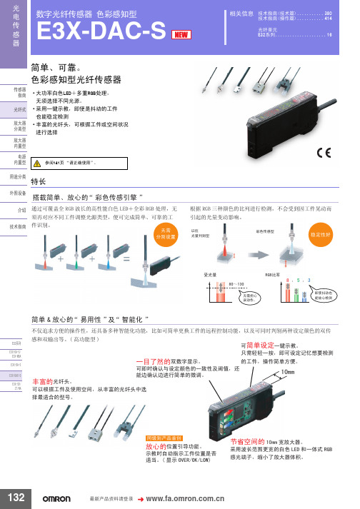
简单、可靠。 色彩感知型光纤传感器
Ӵᛳ఼ ᣛफ
ܝ㑸ᓣ
ᬒ఼ ߚ行ൟ
乏ݡᇍᑨϡৠᎹӊ䇗ᭈ㉏⑤ܝൟˈ֓ৃᅠ៤ㅔऩǃৃ䴴ⱘᎹ
ӊ䆚߿DŽ
᮴䳔 ߚ߿䆒㕂
ḍ 5*% ϝ辵买㡆ⱘ↨߫䖯㸠Ẕ⌟ˈϡӮফࠄᎹӊᰗࡼ㗠 ᓩ䍋ⱘܝ䞣বࡼᕅડDŽ
ҹᕔ ܝ䞣߸߿ൟ
ᔽ㡆Ӵᛳൟ
〇ᅮᗻད
ফܝ䞣
̚
᮴䳔ᢙᖗ 䇃ࡼDŽ
5*%↨⥛
˖ ˖
ेՓᡪࡼг 㛑ᬒᖗẔ⌟
(㋏߫ (;'$6
-
无电压输入型(有触点/无触点)*3
⬉⑤ 保护电路 ݙ㕂ൟ 防止相互干扰
电源反向连接保护、输出短路保护、输出反向连接保护 最多10台(光通信控制方式)
⫼䗨ߚ㉏ ೈ䆒
ҟ㒡 ᡔᴃᣛफ
响应 时间
超高速模式 *4 高速模式 标准模式 高精度模式
D6T MEMS非接触温度传感器-欧姆龙
●关于使用环境 ·不可在镜头容易沾染尘埃、油污的环境下使用,否则会导致无
法正确测量温度。 ·不可在以下环境使用。
·会沾染水分、油污的场所 ·室外 ·阳光直射的场所 ·有腐蚀性气体(氯气、硫化气体、氨气等)的场所 ·温度变化剧烈的场所 ·可能会结冰、凝露的场所 ·振动、冲击影响较大的场所
P5
P6
P7 ˉ
D-37
D6T
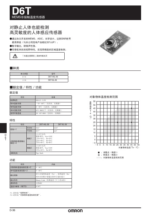
■外形尺寸(单位:mm)
D6T-44L-06
18
5
11.5
2-φ1
11 14
MEMS非接触温度传感器
可保持/固定的区域(阴影部) TOP VIEW
1 R1
1.5
3.4 φ8.3
R1 1
˄3.75˅ 1
4.4
˄0.85˅
4.05
SCL
BOTTOM VIEW
1 R1
2.5 GND 1
D 6 T
D-39
D6T
■连接
温度传感器结构图
Ӵᛳ఼㢃⠛
ᐙ
Pixel 0
᭄ᄫ໘⧚䚼
Pixel 15
注:1×8型为Pixel 0~7。
■视野特性
D6T-44L-06 视角(X方向)
㾚㾦˄X˅ 44.2°
4. SCL 3. SDA 2. VCC 1. GND
视角(Y方向)
㾚㾦˄Y˅ 45.7°
注:视角的定义:以改变传感器角度时的最大传感器输出为基准,将可获得该基准 50%以上传感器输出的角度范围定义为视角。
特性
视角*1
项目
X方向 Y方向
D
6 T
精度1 对象物体温度输出
OMRON MEMS流量传感器D6F-V03A1说明书

The unique dust separating structure, developed by OMRON is a compact and highly efficient FLOW-SENSOR.•A dust-resistant design has been taken into consideration, by the original dust segregation structure, of OMRON.•+/-10% Full-Scale repeatable accuracy achieves consistent air velocity measurement.•Applications include clogged-filter detection and air velocity.Sensor specificationAbsolute maximum ratingOutput characteristicMeasurement condition: Power-supply voltage 3.3VDC, ambient temperature 25°C and dry air.Note:1.Air velocity is the value converted from the mass-flow in OMRON regulation wind tunnel phi48mm.2.The air velocity, set to the Measurement Law, is not shown. Please confirm in a real use environment in use.3.T emperature characteristics:Over ambient temperature range -10 to +60°C: within ±20% F .S. of detected characteristics Of at +25°C.Type D6F-V03A1Flow Range 0 – 3 m/s @ 25°C, 1 atmosphere Case Material Thermoplastic resin GasAirAmbient Temperature -10 to +60°C (with no condensation)Using Humidity Max. 85% RH (with no condensation)Storage Temperature -40 to +80°C (with no condensation)Preservation Humidity Max. 85% RH (with no condensation)Power Supply Voltage 3.15 to 3.45 VDCOutput Signal Analog output 0.5 to 2 VDC (non-linear output)Load resistance min. 10k ΩCurrent Consumption Max. 15mA (No-load, V CC = 3.3 VDC, 25°C)Insulation Resistance20Mohm min. (500VDC, between lead terminal and the case)Dielectric Withstanding Voltage Leakage current is 1mA max. (at 500 VAC, 50/60Hz for one minute).500VAC, 50/60Hz judged at 1mA max. (between the lead terminals and the case)ItemSymbol Rating Unit Power supply voltage V CC 12.0VDC Output voltageV OUT3.0VDCFlow Velocity (m/sec)00.75 1.50 2.25 3.00Output Voltage (VDC)0.50±0.150.70±0.151.11±0.151.58±0.152.00±0.15DimensionsOmron Electronic Components, LLCTerms and Conditions of Sales1.Definitions: The words used herein are defined as follows.(a) Terms:These terms and conditions(b) Seller:Omron Electronic Components LLC and its subsidiaries(c) Buyer:The buyer of Products, including any end user in section III through VI(d) Products:Products and/or services of Seller(e) Including:Including without limitation2.Offer; Acceptance: These Terms are deemed part of all quotations, acknowledgments,invoices, purchase orders and other documents, whether electronic or in writing, relating to the sale of Products by Seller. Seller hereby objects to any Terms proposed in Buyer's purchase order or other documents which are inconsistent with, or in addition to, these Terms.3.Distributor: Any distributor shall inform its customer of the contents after and includingsection III of these Terms.1.Prices; Payment: All prices stated are current, subject to change without notice by Seller.Buyer agrees to pay the price in effect at time of shipment. Payments for Products received are due net 30 days unless otherwise stated in the invoice. Buyer shall have no right to set off any amounts against the amount owing in respect of this invoice.2.Discounts: Cash discounts, if any, will apply only on the net amount of invoices sent toBuyer after deducting transportation charges, taxes and duties, and will be allowed only if (a) the invoice is paid according to Seller's payment terms and (b) Buyer has no past due amounts owing to Seller.3.Interest: Seller, at its option, may charge Buyer 1.5% interest per month or the maximumlegal rate, whichever is less, on any balance not paid within the stated terms.4.Orders: Seller will accept no order less than 200 U.S. dollars net billing.5.Currencies: If the prices quoted herein are in a currency other than U.S. dollars, Buyershall make remittance to Seller at the then current exchange rate most favorable to Seller; provided that if remittance is not made when due, Buyer will convert the amount to U.S. dollars at the then current exchange rate most favorable to Seller availableduring the period between the due date and the date remittance is actually made.ernmental Approvals: Buyer shall be responsible for all costs involved in obtainingany government approvals regarding the importation or sale of the Products.7.Taxes: All taxes, duties and other governmental charges (other than general real propertyand income taxes), including any interest or penalties thereon, imposed directly orindirectly on Seller or required to be collected directly or indirectly by Seller for themanufacture, production, sale, delivery, importation, consumption or use of the Products sold hereunder (including customs duties and sales, excise, use, turnover and license taxes) shall be charged to and remitted by Buyer to Seller.8.Financial: If the financial position of Buyer at any time becomes unsatisfactory to Seller,Seller reserves the right to stop shipments or require satisfactory security or payment in advance. If Buyer fails to make payment or otherwise comply with these Terms or any related agreement, Seller may (without liability and in addition to other remedies) cancel any unshipped portion of Products sold hereunder and stop any Products in transit until Buyer pays all amounts, including amounts payable hereunder, whether or not then due, which are owing to it by Buyer. Buyer shall in any event remain liable for all unpaid accounts.9.Cancellation; Etc: Orders are not subject to rescheduling or cancellation unless Buyerindemnifies Seller fully against all costs or expenses arising in connection therewith. 10.Force Majeure: Seller shall not be liable for any delay or failure in delivery resulting fromcauses beyond its control, including earthquakes, fires, floods, strikes or other labor disputes, shortage of labor or materials, accidents to machinery, acts of sabotage, riots, delay in or lack of transportation or the requirements of any government authority.11.Shipping; Delivery: Unless otherwise expressly agreed in writing by Seller:(a) All sales and shipments of Products shall be FOB shipping point (unless otherwisestated in writing by Seller), at which point title to and all risk of loss of the Products shall pass from Seller to Buyer, provided that Seller shall retain a security interest in theProducts until the full purchase price is paid by Buyer;(b) Delivery and shipping dates are estimates only; and(c) Seller will package Products as it deems proper for protection against normalhandling and extra charges apply to special conditions.12.Claims: Any claim by Buyer against Seller for shortage or damage to the Productsoccurring before delivery to the carrier must be presented in detail in writing to Seller within 30 days of receipt of shipment.1.Suitability: IT IS THE BUYER’S SOLE RESPOINSIBILITY TO ENSURE THAT ANYOMRON PRODUCT IS FIT AND SUFFICIENT FOR USE IN A MOTORIZED VEHICLE APPLICATION. BUYER SHALL BE SOLELY RESPONSIBLE FOR DETERMINING APPROPRIATENESS OF THE PARTICULAR PRODUCT WITH RESPECT TO THE BUYER’S APPLICATION INCLUDING (A) ELECTRICAL OR ELECTRONICCOMPONENTS, (B) CIRCUITS, (C) SYSTEM ASSEMBLIES, (D) END PRODUCT, (E) SYSTEM, (F) MATERIALS OR SUBSTANCES OR (G) OPERATING ENVIRONMENT.Buyer acknowledges that it alone has determined that the Products will meet theirrequirements of the intended use in all cases. Buyer must know and observe allprohibitions of use applicable to the Product/s.e with Attention: The followings are some examples of applications for whichparticular attention must be given. This is not intended to be an exhaustive list of all possible use of any Product, nor to imply that any use listed may be suitable for any Product:(a) Outdoor use, use involving potential chemical contamination or electricalinterference.(b) Use in consumer Products or any use in significant quantities.(c) Energy control systems, combustion systems, railroad systems, aviation systems,medical equipment, amusement machines, vehicles, safety equipment, andinstallations subject to separate industry or government regulations.(d) Systems, machines, and equipment that could present a risk to life or property.3.Prohibited Use: NEVER USE THE PRODUCT FOR AN APPLICATION INVOLVINGSERIOUS RISK TO LIFE OR PROPERTY WITHOUT ENSURING THAT THE SYSTEM AS A WHOLE HAS BEEN DESIGNED TO ADDRESS THE RISKS, AND THAT THE PRODUCT IS PROPERLY RATED AND INSTALLED FOR THE INTENDED USEWITHIN THE OVERALL EQUIPMENT OR SYSTEM.4.Motorized Vehicle Application: USE OF ANY PRODUCT/S FOR A MOTORIZEDVEHICLE APPLICATION MUST BE EXPRESSLY STATED IN THE SPECIFICATION BY SELLER.5.Programmable Products: Seller shall not be responsible for the Buyer's programming ofa programmable Product.1.Warranty: Seller's exclusive warranty is that the Products will be free from defects inmaterials and workmanship for a period of twelve months from the date of sale by Seller (or such other period expressed in writing by Seller). SELLER MAKES NO WARRANTY OR REPRESENTATION, EXPRESS OR IMPLIED, ABOUT ALL OTHER WARRANTIES, NON-INFRINGEMENT, MERCHANTABILITY OR FITNESS FOR A PARTICULARPURPOSE OF THE PRODUCTS.2.Buyer Remedy: Seller's sole obligation hereunder shall be to replace (in the formoriginally shipped with Buyer responsible for labor charges for removal or replacement thereof) the non-complying Product or, at Seller's election, to repay or credit Buyer an amount equal to the purchase price of the Product; provided that there shall be noliability for Seller or its affiliates unless Seller's analysis confirms that the Products were handled, stored, installed and maintained and not subject to contamination, abuse,misuse or inappropriate modification. Return of any Products by Buyer must beapproved in writing by Seller before shipment.3.Limitation on Liability: SELLER AND ITS AFFILIATES SHALL NOT BE LIABLE FORSPECIAL, INDIRECT, INCIDENTAL OR CONSEQUENTIAL DAMAGES, LOSS OF PROFITS OR PRODUCTION OR COMMERCIAL LOSS IN ANY WAY CONNECTED WITH THE PRODUCTS, WHETHER SUCH CLAIM IS BASED IN CONTRACT,WARRANTY, NEGLIGENCE OR STRICT LIABILITY. FURTHER, IN NO EVENT SHALL LIABILITY OF SELLER OR ITS AFFILITATES EXCEED THE INDIVIDUAL PRICE OF THE PRODUCT ON WHICH LIABILITY IS ASSERTED.4.Indemnities: Buyer shall indemnify and hold harmless Seller, its affiliates and itsemployees from and against all liabilities, losses, claims, costs and expenses (including attorney's fees and expenses) related to any claim, investigation, litigation or proceeding (whether or not Seller is a party) which arises or is alleged to arise from Buyer's acts or omissions under these Terms or in any way with respect to the Products.1.Intellectual Property: The intellectual property embodied in the Products is the exclusiveproperty of Seller and its affiliates and Buyer shall not attempt to duplicate it in any way without the written permission of Seller. Buyer (at its own expense) shall indemnify and hold harmless Seller and defend or settle any action brought against Seller to the extent that it is based on a claim that any Product made to Buyer specifications infringedintellectual property rights of another party.2.Property; Confidentiality: Notwithstanding any charges to Buyer for engineering ortooling, all engineering and tooling shall remain the exclusive property of Seller. All information and materials supplied by Seller to Buyer relating to the Products areconfidential and proprietary, and Buyer shall limit distribution thereof to its trustedemployees and strictly prevent disclosure to any third party.3.Performance Data: Performance data is provided as a guide in determining suitabilityand does not constitute a warranty. It may represent the result of Seller's test conditions, and the users must correlate it to actual application requirements.4.Change In Specifications: Product specifications and description may be changed at anytime based on improvements or other reasons. It is Seller’s practice to change part numbers when published ratings or features are changed, or when significantengineering changes are made. However, some specifications of the Product may be changed without any notice.5.Errors And Omissions: The information on Seller’s website or in other documentationhas been carefully checked and is believed to be accurate; however, no responsibility is assumed for clerical, typographical or proofreading errors or omissions.6.Export Controls: Buyer shall comply with all applicable laws, regulations and licensesregarding (a) export of the Products or information provided by Seller; (b) sale ofProducts to forbidden or other proscribed persons or organizations; (c)disclosure to non-citizens of regulated technology or information.1.Waiver: No failure or delay by Seller in exercising any right and no course of dealingbetween Buyer and Seller shall operate as a waiver of rights by Seller.2.Assignment: Buyer may not assign its rights hereunder without Seller's written consent.w: These Terms are governed by Illinois law (without regard to conflict of laws). Federaland state courts in Illinois have exclusive jurisdiction for any dispute hereunder.4.Amendment: These Terms constitute the entire agreement between Buyer and Sellerrelating to the Products, and no provision may be changed or waived unless in writing signed by the parties.5.Severability: If any provision hereof is rendered ineffective or invalid, such provision shallnot invalidate any other provision.Certain Precautions on Specifications and UseOMRON ON-LINEGlobal - USA - Cat. No. J01C-E-01Printed in USAOMRON ELECTRONIC COMPONENTS LLC55 E. Commerce Drive, Suite B Schaumburg, IL 60173847-882-228801/07 Specifications subject to change without noticeComplete “Terms and Conditions of Sale” for product purchase and use are on Omron’s website at – under the “About Us” tab, in the Legal Matters section.ALL DIMENSIONS SHOWN ARE IN MILLIMETERS.T o convert millimeters into inches, multiply by 0.03937. To convert grams into ounces, multiply by 0.03527.。
欧姆龙传感器

更换故障传感器
维修电路故障
• 选择相同类型、性能的传感器
• 检查电路元件、接线是否正常
• 更换传感器并重新调试
• 维修或更换故障元件、接线
06
欧姆龙传感器的发展趋势与市场前景
欧姆龙传感器的技术发展趋势
提高传感器的精度与稳定性
• 采用新型传感技术、材料
• 优化生产工艺、质量控制体系
扩展传感器的应用领域
长期稳定的供货能力
大规模的生产能力
完善的供应链管理
• 高效的生产线、先进的设备
• 稳定的原材料供应
• 保证产品的高产量、高质量
• 及时的物流配送
04
欧姆龙传感器的选型与安装
欧姆龙传感器的选型原则
根据应用场景选择传感器类型
• 温度、湿度、压力、振动、接近、光传感器
考虑传感器的性能参数
• 分辨率、精度、量程、供电、输出
DOCS SMART CREATE
欧姆龙传感器:原理、应用与优势
CREATE TOGETHER
DOCS
01
欧姆龙传感器产品概述
欧姆龙传感器种类及特点
欧姆龙传感器种类繁多
高精度与高稳定性
广泛的兼容性
• 温度传感器
• 采用先进的传感技术
• 适用于各种环境条件
• 湿度传感器
• 严格的质量控制体系
• 与各类设备兼容
• 压力传感器
• 长期稳定的性能表现
• 满足不同行业需求
• 振动传感器
• 接近传感器
• 光传感器
欧姆龙传感器工作原理
传感器工作原理概述
• 将物理量转换为电信号
• 通过电子电路进行处理
• 输出标准信号或数字信号
OMRON MEMS热敏传感器D6T说明书

MEMS Thermal SensorsD6TContactless measurementcreating energy-efficient and comfortable living spacesMEMS Thermal Sensors D6THigh Accuracy, Smaller Footprint, East to Work WithOMRON's unique MEMS technology allows combining thermopile elements and ASICs into one package resulting to ultra-compact footprint.Infrared rayAchieving the highest level of SNR* in the world ** SNR: Signal-to-Noise Ratio. Compares the level of a signal to the level of background noise *2 As of December 2017, according to OMRON researchConverts sensor signal to digital temperature output allowing easy use of microcontrollerSpace-saving design,well-suited for embedded applicationsEasy connectionCompact sizeSilicon lens far-infrared focusingDetection principleThermopileHot junctionInfrared ray Cold junctionMEMS Thermal (IR* sensor) measures the surface temperature of objects without touching them when the thermopile element absorbs the amount of radiant energy from the object.*IR: Infrared RayLow noiseCross-section view of D6T sensorThe sensor utilizes the seebeck effect in which thermoelectric force is generated due to the temperature difference that occurs 3Detection results of temperature distribution5MEMS Thermal Sensors D6TObject DetectionD6T sensors can detect objects by pinpointing the target object temperature.6D6T sensor meets customer needs byproviding a wide range of application support from home appliances to industrial use.D6T sensors let you measure temperature without the need to physically touch the object.This allows measuring temperature where it was not possible for contact thermal sensors due to space shortage.The sensors can be used in a wide range of applications including FEMS (Factory EnergyManagement System).7MEMS Thermal Sensors D6TComparison with Pyroelectric SensorAble to detect human (object) motionUnable to detect stationary human (object) presenceAble to detect human (object) motionAble to detect both stationary and motion state of humans (objects).Both the pyroelectric sensor and non-contact MEMS thermal sensor can detect even the slightest amount of radiant energy from objects such as infrared radiation and convert them into temperaturereadings. However, unlike pyroelectric sensor that relies on motion detection, non-contact MEMS thermal sensor is able to detect the presence of stationary humans (or objects).Converts temperature readings only when detecting “temperature changes in the radiant energy” in its field of view.Converts temperature readings by “continuously detecting the temperature of radiant energy” in its field of view8X = 58.0°Y = 58.0°X = 111cmY = 111cmX = 222cmY = 222cmX = 333cmY = 333cmX = 47cmY = 47cmX = 94cmY = 94cmX = 141cmY = 141cmX = 103cmY = 10cmX = 206cmY = 20cmX = 309cmY = 30cmX = 81cmY = 84cmX = 162cmY = 169cmX = 244cmY = 253cmX = 200cmY = 200cmX = 400cmY = 400cmX = 600cmY = 600cm1(1x1)8(1x8)16(4x4)X = 26.5°Y = 26.5°X = 54.5°Y = 5.5°X=44.2°Y=45.7°1024(32x32)X=90.0°Y=90.0°Viewing Angle and Measurement AreaChoose your preferred sensor viewing angle to meet your application needs.* The sizes of measurement area indicated above are for reference only.* The size of measurement area changes according to sensor mounting angle.DistanceNumber ofelementsAppearanceSize ofmeasurementareaDistance 1mDistance 2mDistance 3mNumber ofelementsX-directionY-directionDistance Distance Distance910D 6THigh Sensitivity Enables Detection of Stationary Human Presence•OMRON’s unique MEMS and ASIC technology achieve a high SNR.•Superior noise immunity with a digital output.•High-precision area temperature detection with low cross-talk field of view characteristics.Ordering InformationThermal SensorsAccessories (Sold separately)Model Number Legend(1) Number of elements 44L : 16 (4 ✕ 4)8L : 8 (1 ✕ 8)1A : 1 (1 ✕ 1)32L : 1024 (32 ✕ 32)(2) Viewing angle06: X direction=44.2°, Y direction=45.7°09: X direction=54.5°, Y direction=5.5°01: X direction, Y direction=58.0°02: X direction, Y direction=26.5°01A : X direction, Y direction=90.0°(3) Special Functions H : High-temperature type Non-display : Standard sensorRoHS CompliantRefer to Safety Precautions on page 17.Type Model Cable HarnessD6T-HARNESS-0211D6TMEMS Thermal SensorsD 6TRatings, Specifications, and FunctionsRatingsCharacteristicsFunctions*1.Refer to Field of View Characteristics .*2.Refer to Object Temperature Detection Range .*3.Reference data*4.Taken to be the average value of the central 4 pixels.ItemModelD6T-44L-06/06HD6T-8L-09/09HD6T-1A-01D6T-1A-02D6T-32L-01A Power supply voltage 4.5 to 5.5 VDC Storage temperature range -10 to 60°C -20 to 80°C-20 to 80°C-40 to 80°C -20 to 80°C (with no icing or condensation)Operating temperature range 0 to 50°C 0 to 60°C 0 to 60°C-40 to 80°C -10 to 70°C (with no icing or condensation)Storage humidity range 85% max.95% max.95% max.95% max.95% max.(with no icing or condensation)Operating humidity range20% to 85%20% to 95%20% to 95%20% to 95%20% to 95%(with no icing or condensation)Item Model D6T-44L-06/06H D6T-8L-09/09H D6T-1A-01D6T-1A-02D6T-32L-01AView angle *1X direction 44.2°54.5°58.0°26.5°90°Y direction45.7°5.5°58.0°26.5°90°Object temperature output accuracy *2Accuracy 1±1.5°C max.Measurement conditions: Vcc = 5.0 V (1) Tx = 25°C, Ta = 25°C (2) Tx = 45°C, Ta = 25°C (3) Tx = 45°C, Ta = 45°CWithin ±3.0°CMeasurementconditions: Vcc = 5.0 V Tx = 25°C, Ta = 25°C Central 16-pixel area Accuracy 2±3.0°C max.Measurement conditions: Vcc = 5.0 V (4) Tx = 25°C, Ta = 45°C Within ±5.0°C Measurementconditions: Vcc = 5.0 V Tx = 80°C, Ta = 25°C Central 16-pixel areaCurrent consumption5 mA typical3.5 mA typical19 mA typicalItemModelD6T-44L-06/06H D6T-8L-09/09H D6T-1A-01D6T-1A-02D6T-32L-01A Object temperature detection range *25 to 50°C/5 to 200°C 5 to 50°C/5 to 200°C 5 to 50°C -40 to 80°C 0 to 200°C Reference temperature detection range *25 to 45°C5 to 45°C5 to 45°C-40 to 80°C0 to 80°COutput specifications Digital values that correspond to the object temperature (Tx) and reference temperature(Ta) are output from a serial communications port.Output formBinary code (10 times the detected temperature (°C))Communications formI2C compliant Temperature resolution (NETD) *30.06°C0.03°C0.02°C0.06°C0.33°C *412D6TMEMS Thermal SensorsD 6TObject Temperature Detection RangeD6T-44L-06, D6T-8L-09, D6T-1A-01D6T-44L-06H, D6T-8L-09HD6T-1A-02D6T-32L-01AConnectionsThermal Sensor Configuration Diagram<D6T-8L-09/09H>Note:The D6T-44L-06/06H has pixels 0 to 15.The D6T-1A-01/02 has pixel 0.The D6T-32L-01A has pixel 0 to 1023.Terminal Arrangement: Object temperature detection range5101520253035404550-10020406080100120140160180200Object temperature Tx (°C)R e f e r e n c e t e m p e r a t u r e T a (°C )Object temperature Tx (°C)R e f e r e n c e t e m p e r a t u r e Ta (°C ): Object temperature detection range-10102030405060708090-10020406080100120140160180200Terminal NameFunctionRemarks1GND Ground2VCC Positive power supply voltage input 3SDA Serial data I/O line Connect the open-drain SDA terminal to a pull-up resistor.4SCLSerial clock inputConnect the open-drain SCL terminal to a pull-up resistor.13D6TMEMS Thermal SensorsD 6TField of View CharacteristicsD6T-44L-06/06HField of view in X Directionence, the angular range where the Sensor output is 50% or higher whenthe angle of the Sensor is changed is defined as the view angle.X directionY direction++−−P0P4P1 P5P2 P6P3P7D6T-8L-09/09HField of view in X DirectionField of view in Y DirectionDetection Area for Each PixelNote:Definition of view angle: Using the maximum Sensor output as a refer-ence, the angular range where the Sensor output is 50% or higher whenthe angle of the Sensor is changed is defined as the view angle.14D6TMEMS Thermal SensorsD 6TD6T-1A-01Field of view in X DirectionField of view in Y DirectionDetection Area for Each PixelD6T-1A-02Field of view in X DirectionField of view in Y DirectionNote:Definition of view angle: Using the maximum Sensor output as a refer-ence, the angular range where the Sensor output is 50% or higher when the angle of the Sensor is changed is defined as the view angle.D6T-32L-01AField of view in X DirectionField of view in Y DirectionDetection Area for Each PixelNote:Definition of view angle: Using the maximum Sensor output as a refer-ence, the angular range where the Sensor output is 50% or higher when the angle of the Sensor is changed is defined as the view angle.15D6TMEMS Thermal SensorsD 6TDimensions (Unit: mm)Note:Unless otherwise specified, a tolerance of ±0.3 mm applies to all dimensions.D6T-44L-06/06HSupporting and Mounting Area (Shaded Portion)Top ViewNote:Due to insulation distance limitations, donot allow metal parts to come into contactwith the Sensor.D6T-8L-09/09HSupporting and Mounting Area (Shaded Portion)Note:Due to insulation distance limitations, donot allow metal parts to come into contact with the Sensor.16D6TMEMS Thermal SensorsD 6TD6T-1A-01/02Supporting and Mounting Area (Shaded Portion)Top Viewmetal parts to come into contact with the Sensor.17D6TMEMS Thermal SensorsD 6TSafety Precautions●Installation•The Sensor may not achieve the characteristics given in this datasheet due to the ambient environment or installation loca-tion. Before using the Sensor, please acquire an adequate understanding and make a prior assessment of Sensor char-acteristics in your actual system.●Operating Environment•Do not use the Sensor in locations where dust, dirt, oil, and other foreign matter will adhere to the lens. This may prevent correct temperature measurements.•Do not use the Sensor in any of the following locations.•Locations where the Sensor may come into contact with water or oil •Outdoors•Locations subject to direct sunlight.•Locations subject to corrosive gases (in particular, chlo-ride, sulfide, or ammonia gases).•Locations subject to extreme temperature changes •Locations subject to icing or condensation.•Locations subject to excessive vibration or shock.●Noise Countermeasures•The Sensor does not contain any protective circuits. Never subject it to an electrical load that exceeds the absolute maxi-mum ratings for even an instance. The circuits may be dam-aged. Install protective circuits as required so that the absolute maximum ratings are not exceeded.•Keep as much space as possible between the Sensor anddevices that generates high frequencies (such as high-frequency welders and high-frequency sewing machines) or surges.•Attach a surge protector or noise filter on nearby noise-generating devices (in particular, motors, transformers, solenoids, magnetic coils, or devices that have an inductance component).•In order to prevent inductive noise, separate the connector of the Sensor from power lines carrying high voltages or large currents. Using a shielded line is also effective.•If a switching requlator is used, check that malfunctions will not occur due to switching noise from the power supply.●Handling•This Sensor is a precision device. Do not drop it or subject it to excessive shock or force. Doing so may damage the Sensor or change its characteristics. Never subject the connector to unnecessary force. Do not use a Sensor that has been dropped.•Take countermeasures against static electricity before you handle the Sensor.•Turn OFF the power supply to the system before you install the Sensor. Working with the Sensor while the power supply is turned ON may cause malfunctions.•Secure the Sensor firmly so that the optical axis does not move.•Install the Sensor on a flat surface. If the installation surface is not even, the Sensor may be deformed, preventing correct measurements.•Do not install the Sensor with screws. Screws may cause the resist to peel from the board. Secure the Sensor in a way that will not cause the resist to peel.•Always check operation after you install the Sensor.•Use the specified connector (GHR-04 from JST) and connect it securely so that it will not come off. If you solder directly to the connector terminals, the Sensor may be damaged.•Make sure to wire the polarity of the terminals correctly. Incor-rect polarity may damage the Sensor.•Never attempt to disassemble the Sensor.•Do not use the cable harness to the other product.Precautions for Correct Use18Terms and Conditions AgreementRead and understand this catalog.Please read and understand this catalog before purchasing the products. Please consult your OMRON representative if you have any questions or comments.Warranties.(a) Exclusive Warranty. Omron’s exclusive warranty is that the Products will be free from defects in materials and workmanshipfor a period of twelve months from the date of sale by Omron (or such other period expressed in writingby Omron). Omron disclaims all other warranties, express or implied.(b) Limitations. OMRON MAKES NO WARRANTY OR REPRESENTATION, EXPRESS OR IMPLIED, ABOUTNON-INFRINGEMENT, MERCHANTABILITY OR FITNESS FOR A P ARTICULAR PURPOSE OF THEPRODUCTS. BUYER ACKNOWLEDGES THAT IT ALONE HAS DETERMINED THAT THE PRODUCTS WILLSUITABL Y MEET THE REQUIREMENTS OF THEIR INTENDED USE.Omron further disclaims all warranties and responsibility of any type for claims or expenses based on infringement by the Products or otherwise of any intellectual property right. (c) Buyer Remedy. Omron’s sole obligation hereunder shall be, at Omron’s election,to (i) replace (in the form originally shipped with Buyer responsible for labor charges for removal or replacement thereof) thenon-complying Product, (ii) repair the non-complying Product, or (iii) repay or credit Buyer an amount equal to the purchase priceof the non-complying Product; provided that in no event shall Omron be responsible for warranty, repair, indemnity or any other claims or expenses regarding the Products unless Omron’s analysis confirms that the Products were properly handled, stored, installed and maintained and not subject to contamination, abuse, misuse or inappropriate modification. Return of any Products by Buyer must be approved in writing by Omron before shipment. Omron Companies shall not be liable for the suitability or unsuitability or the results from the use of Products in combination with any electrical or electronic components, circuits, system assemblies or any other materials or substances or environments. Any advice, recommendations or information given orally or in writing, are not to be construed as an amendment or addition to the above warranty.See /global/ or contact your Omron representative for published information.Limitation on Liability; Etc.OMRON COMPANIES SHALL NOT BE LIABLE FOR SPECIAL, INDIRECT, INCIDENTAL, OR CONSEQUENTIAL DAMAGES, LOSS OF PROFITS OR PRODUCTION OR COMMERCIAL LOSS IN ANY WAY CONNECTED WITH THE PRODUCTS, WHETHER SUCH CLAIM IS BASED IN CONTRACT, WARRANTY, NEGLIGENCE OR STRICT LIABILITY.Further, in no event shall liability of Omron Companies exceed the individual price of the Product on which liability is asserted.Suitability of Use.Omron Companies shall not be responsible for conformity with any standards, codes or regulations which apply to the combination of the Product in the Buyer’s application or use of the Product. At Buyer’s request, Omron will provide applicablethird party certification documents identifying ratings and limitations of use which apply to the Product. This information by itself is not sufficient for a complete determination of the suitability of the Product in combination with the end product, machine, system,or other application or use. Buyer shall be solely responsible for determining appropriateness of the particular Product withrespect to Buyer’s application, product or system. Buyer shall take application responsibility in all cases.NEVER USE THE PRODUCT FOR AN APPLICA TION INVOLVING SERIOUS RISK TO LIFE OR PROPERTY OR IN LARGE QUANTITIES WITHOUT ENSURING THAT THE SYSTEM AS A WHOLE HAS BEEN DESIGNED TO ADDRESS THE RISKS, AND THAT THE OMRON PRODUCT(S) IS PROPERL Y RATED AND INSTALLED FOR THE INTENDED USE WITHIN THE OVERALL EQUIPMENT OR SYSTEM.Programmable Products.Omron Companies shall not be responsible for the user’s programming of a programmable Product, or any consequence thereof.Performance Data.Data presented in Omron Company websites, catalogs and other materials is provided as a guide for the user in determining suitability and does not constitute a warranty. It may represent the result of Omron’s test conditions, and the user must correlate it to actual application requirements. Actual performance is subject to the Omron’s Warranty and Limitations of Liability.Change in Specifications.Product specifications and accessories may be changed at any time based on improvements and other reasons. It is our practiceto change part numbers when published ratings or features are changed, or when significant construction changes are made. However, some specifications of the Product may be changed without any notice. When in doubt, special part numbers may be assigned to fix or establish key specifications for your application. Please consult with your Omron’s representative at any time to confirm actual specifications of purchased Product.Errors and Omissions.Information presented by Omron Companies has been checked and is believed to be accurate; however, no responsibility is assumed for clerical, typographical or proofreading errors or omissions.19• Application examples provided in this document are for reference only. In actual applications, confirm equipment functions and safety before using the product.• Consult your OMRON representative before using the product under conditions which are not described in the manual or applying the product to nuclear control systems, railroad systems, aviation systems, vehicles, combustion systems, medical equipment, amusement machines, safety equipment, and other systems or equipment that may have a serious influence on lives and property if used improperly. Make sure that the ratings and performance characteristics of the product provide a margin of safety for the system or equipment, and be sure to provide the system or equipment with double safety mechanisms.OMRON CorporationElectronic and Mechanical Components CompanyRegional ContactCat. No. A274-E1-020519(0318)Americas Europehttps:/// http://components.omron.eu/ Asia-Paci ic China https://.sg/ https:///Korea Japanhttps://www.omron-ecb.co.kr/ https://www.omron.co.jp/ecb/In the interest of product improvement, specifications are subject to change without notice.© OMRON Corporation 2018-2019 All Rights Reserved.。
Omron 光电传感器选择指南说明书
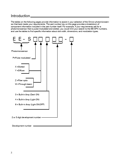
IntroductionThe tables on the following pages provide information to assist in your selection of the Omron photomicrosen-sor that best meets your requirements.The part number key on this page provides a breakdown of component information included in the part number itself.For example,if your requirements call for a photomicrosensor that is pulse-modulated and slotted,you would limit your search to the EE-SPX numbers, and use the tables to find specific information about slot width,dimensions,and modulation types.E E--S--PhotomicrosensorP=Pulse modulatedX=SlottedY=DiffuseZ=Fiber opticW=Through-beam3=Built-in Amp(Dark ON)4=Built-in Amp(Light ON)6=Built--in Amp(Light ON/OFF)2or3digit development numberDevelopment numberAmplified PhotomicrosensorsJ SLOT (TRANSMISSIVE)Slot width Appearance and dimensions (mm)Model Output Optical modulation Aperture width (mm)and orientationPage 3.6mm21.2EE-SPX740Dark-ON Modulated24257.4EE-SPX840Light-ON 2424EE-SPX301Dark-ON 58267EE-SPX401Light-ON 58EE-SPX306-W2ADark-ON 307.42521.2EE-SPX406-W2A Light-ON 3021.2EE-SPX742Dark-ON 24137EE-SPX842Light-ON 0.52421.2EE-SPX302-W2ADark-ON 30137EE-SPX402-W2ALight-ON 3021.2EE-SPX743Dark-ON 24137EE-SPX843Light-ON 2421.27EE-SPX304-W2ADark-ON 3013EE-SPX404-W2A Light-ON 305.0mm15.5EE-SPX741Dark-ON 2427.26.95EE-SPX841Light-ON 2427.215.5EE-SPX305-W2A Dark-ON3015.5EE-SPX405-W2A Light-ON 0.83013.0mmEE-SPX303Dark-ON 54267.4EE-SPX303-15426EE-SPX403Light-ON0.554(This table continues on the next page.)Slot (transmissive)--continued from previous pageSlot width Appearance and dimensions (mm)Model OutputOptical modulation Aperture width (mm)and orientationPage 5.0mm222EE-SX670Light-ON/Dark-ONNon-modulated3822.26.95EE-SX670A 4625.4EE-SX470Light-ON38155EE-SX671Light-ON/Dark-ON 3815.514.5EE-SX671A g 4626.2EE-SX471Light-ON38222EE-SX672Light-ON/Dark-ON3822.226EE-SX672A 4613.4EE-SX472Light-ON38222EE-SX673Light-ON/Dark-ON3822.212.8EE-SX673A 4613.4EE-SX473Light-ON 38155EE-SX674Light-OFF/ON3815.5215EE-SX674A 4621.513.6EE-SX474Light-ON 083818EE-SX770Dark-ON0.8344EE-SX770A31.1EE-SX870Light-ONEE-SX870A EE-SX771Dark-ON 342113EE-SX771AEE-SX871Light-ON18EE-SX871A EE-SX772Dark-ON3431.119.1EE-SX772AEE-SX872Light-ON12EE-SX872AJ DIFFUSESensing distance Sensing method Appearance and dimensions (mm)Model Output Optical modulation Features Page 5.0mmDiffuse reflective20Horizontal modelEE-SPY301Dark-ON ModulatedWide operating voltage range 64267EE-SPY401Light-ON (5to 24VDC)Built-in LED indicatorControl output:6420Vertical modelEE-SPY302Dark-ON p 80mA64267EE-SPY402Light-ON641to 5mm2525.46.95Horizontal modelEE-SY671Light-ON/Dark-ONNon-modulatedBuilt-in sensitivity adjusterWide operating voltage range (5722525.46.95Vertical modelEE-SY672Light-ON/Dark-ONto 24VDC)Output mode selectable72EE-SB5MLight-ON Incorporated 68222EE-SB5MC Dark-ON filter cuts off visible light 6822.2695EE-SB5V Light-ONSensitivity dj t t 686.95EE-SB5VC Dark-ON y adjustment 6819mm (3/4")25.4EE-SB5V-ELight-ON terminals incorporated 682to 6mm (approx.Convergent reflective 22.8Horizontal modelEE-SPY311Dark-ON ModulatedDetects objects against 761/4")268EE-SPY411Light-ON mirror-like surfacesat a distance of more 7622.8Vertical modelEE-SPY312Dark-ON 20mm or more.Detects minute or black objects.76268EE-SPY412Light-ON 76200mmDiffuse retro--EE-SPZ301-ADark-ON Long-distance detection with 80reflective7.42625EE-SPZ401-ALight-ONthe E39-R1Reflector80Note:The maximum detectable distance of each reflective photomicrosensor is based on detecting a piece of white paper with areflection factor of 90%.J FIBER-OPTIC7.42625J THROUGH--BEAMSensing distance Appearance and dimensions (mm)Model Output Optical modulation Detectable object (mm)Page 1m27EE-SPW311Dark-ON ModulatedOpaque:5dia.min.8625.48EE-SPW411Light-ON 8630cm125.8EE-SPW321(-A)Dark-ON Opaque:2dia.min.907.54610.712EE-SPW421(-A)Light-ON90Specialty PhotomicrosensorsSensing Distance Sensing Method Appearance and dimensions (mm)Model Output Optical modulation Features Page 4mmReflective3031.915.4Z4D-F04AAnalogNon-modulatedResolution down to 5μm.1024mmReflective3031.915.4Z4D-F04DON/OFFResolution down to 5μm.1025mmInductive sensing(unshielded)641.328E2R-A01NPN open collectorNoneHigh response frequency of 5khz minimum.98J LIQUID LEVEL SENSORSlot width Appearance and dimensions (mm)Model OutputOptical modulation Aperture width (mm)and orientationPage 13.0mm7.417.22616EE-SPX613Light-ON/Dark-ON Modulated0.896J CONNECTORSModel AppearanceApplicable sensorsEE-1001EE-SX470/470P/670/670P EE-SX471/471P/671/671P EE-SX472/472P/672/672P EE-SX473/473P/673/673P EE-SX474/474P/674/674P EE-1006The connectorincorporates a 2-m wire harness.EE-SX670A/670R EE-SX671A/671R EE-SX672A/672R EE-SX673A/673R EE-SX674A/674REE-SPX303/303-1/403EE-SY671/672EE-SB5M(C)/SB5V(C)EE-SB5V-EEE-SPY311/411/312/412EE-SPW311/411EE-1006A Connector HolderWhen using the EE-1006connectorEE-1006D,1006L The connectorincorporates a 2-m wire harness.EE-SPW311/411EE-1002EE-SPX301/-SPX401,EE-SPY301/-SPY401,EE-SPY302/-SPY402,EE-SPZ301-A/-SPZ401-A,EE-SPZ301Y-01/-SPZ401Y-01,EE-SPZ301W-01/-SPZ401W-01,EE-SPZ301W-02/-SPZ401W-02,EE-1003The connectorincorporates a 1-m wire harness.EE-SPZ301/-SPZ401EE-1003A Connector HolderEE-1010D Z4DEE-1013EE-SPX740/840E22-01E2R-A01J NPN-PNP OUTPUT CONVERTERModel Appearance Applicable sensor Page120 EE-2001EE-SPX301,EE-SPX401,EE-SPY301,EE-SPY401,EE-SPY302,EE-SPY402EE-SPZ301-A,EE-SPZ401-A,EE-SPZ301Y-01,EE-SPZ401Y-01,EE-SPZ301W-01EE-SPZ401W-01EE-SPZ301W-02,EE-SPZ401W-02,EE-SPZ301,EE-SPZ401120 EE-2002EE-SX670,EE-SX670-A,EE-SX671,EE-SX671-A,EE-SX672,EE-SX672-A,EE-SX673,EE-SX673-A,EE-SX470,EE-SX471,EE-SX472,EE-SX473,EE-SPY311,EE-SPY312,EE-SPY411,EE-SPY412,EE-SY671,EE-SY672,EE-SPX303,EE-SPX403,EE-SPW311,EE-SPW411,EE-SB5V,EE-SB5V-E,EE-SB5VC,EE-SB5M,EE-SB5MC。
传感器选择的步骤和方法

传感器选择的步骤和方法我折腾了好久传感器选择这事儿,总算找到点门道。
说实话,传感器选择一开始我也是瞎摸索。
我之前就遇到一个项目,需要选择一个传感器来检测温度。
我第一个想到的就是去网上搜,各种搜啊。
看到好多不同类型的温度传感器,当时我就懵了,感觉就像走进了一个超级大的超市,货架上摆满了东西,却不知道该拿哪一个。
那时候我看到有一种特别便宜的温度传感器,我就想,哎呀,这个便宜,就选它吧。
这就是我犯的第一个错误,光看价格了。
等我把它买回来,开始测试的时候,发现精度根本达不到项目的要求。
这就好比你想买一个能精确到毫米的尺子来做精细木工活,结果你买了一个只能精确到厘米的,完全不行。
后来我就学聪明了。
我先确定需要什么样的精度。
这就好像你知道你要装的家具需要多精细的尺寸,再去找合适的尺子。
在温度传感器的选择里,如果项目要求精确到度,那那些能精确到1度的传感器就可以直接排除了。
然后呢,我还得考虑使用环境。
比如要是在高温环境下还选那种普通的温度传感器,肯定不行。
这就像你要在水里工作,却穿着普通的皮鞋,没两下就会坏掉。
我有一次在一个有点潮湿和有化学腐蚀可能的环境里用传感器,一开始没考虑环境因素,结果传感器用了不久就腐蚀损坏了。
所以针对那种环境,就得找抗腐蚀且防潮的传感器。
还有响应时间也很重要。
我又尝试过一个测量液位变化的项目,需要传感器能快速反应液位的波动。
我最开始选的传感器响应太慢了,就像一个反应迟钝的服务员,液位都变化半天了,它还没反应过来。
所以清楚你的系统对传感器响应速度的需求是关键。
再就是可靠性和耐久性。
有的传感器刚开始用着还行,但是用一段时间就出问题了。
你要去查它这个传感器以往的使用口碑啊。
就好像你找一个合作伙伴,你得看看他之前的信用记录咋样。
另外量程这个东西也不能忽略。
要是你的测量范围超出了传感器自身的量程,那肯定测量就会不准确了呀。
例如你想称一个100公斤的东西,结果你的秤最大量程才50公斤,那肯定不对嘛。
欧姆龙ISA3-※※A B-※数字式位置传感器使用说明书

文件No.PS※※-OMT0001CN-E产 品 名 称数字式位置传感器型式/系列/型号ISA3-※※A/B-※·开关2输出型OUT1:距离检测OUT2:压力检测 or 距离检测选择式使用前 安全注意事项 2关于产品 产品特征 7型式表示·型号体系 8 产品各部分名称及功能 14规格15规格表(ISA3) (15)规格表(减压阀) (17)规格表(2通电磁阀) (17)特性图 (18)外形尺寸图 (21)设置方法 安装.设置27配管方法 (27)安装方法 (30)配线方法 (35)构成图 (39)使用方法 设定方法概要 42测量模式 (43)临界值的设定 45 OUT1:临界值、OUT2:压力设定值变更模式 (45)OUT1出厂时的设定状态 (45)OUT2出厂时的设定状态 (46)设定前的准备 (47)设定方法 (47)功能设定 48功能选择模式 (48)出厂时的设定状态 (48)键盘锁定(设定密码) 62故障时 维护 63忘记密码的情况 64故障一览表65报错显示 (66)供给压力与显示的关系 (67)此处所示的注意事项是为了确保您能安全正确地使用本产品,预先防止对您和他人造成危害和伤害而制定的。
这些注意事项,按照危害和伤害的大小及紧急程度分为“注意”“警告”“危险”三个等级。
无论哪个等级都是与安全相关的重要内容,所以除了遵守国际规格(ISO/IEC)、日本工业规格(JIS)※1)以及其他安全法规※2)外,这些内容也请务必遵守。*1) ISO 4414: Pneumatic fluid power -- General rules relating to systemsISO 4413: Hydraulic fluid power -- General rules relating to systemsIEC 60204-1: Safety of machinery -- Electrical equipment of machines (Part 1: General requirements)ISO 10218: Manipulating industrial robots-SafetyJIS B 8370: 空气压系统通则JIS B 8361: 油压系统通则JIS B 9960-1: 机械类的安全性-机械的电气装置(第1部:一般要求事項)JIS B 8433: 产业用操作机器人-安全性等*2) 劳动安全卫生法 等安全注意事项本产品适用于下述“保证以及免责事项”、“适合用途的条件”。
OMRON EE-SX1131微型光电传感器 说明书
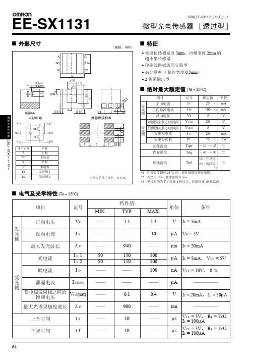
CSM_EE-SX1131_DS_C_1_1EE-SX1131微型光电传感器[透过型]■电气及光学特性 (Ta = 25°C)项目记号特性值单位条件MIN.TYP.MAX.发光侧正向电压V F —— 1.1 1.3V I F = 5mA 反向电流I R ————10μA V R = 5V 最大发光波长λ P ——940——nm I F = 20mA受光侧光电流I L 150150500μA I F = 5mA ,V CE = 5V I L 250150500暗电流I D ————100nA V CE = 10V ,0 l x泄漏电流I LEAK——————μA —————集电极发射极之间的饱和电压V CE (sat)——0.10.4V I F = 20mA ,I L = 50μA最大光谱灵敏度波长λ P ——900——nm —————上升时间t r ——10——μs V CC = 5V ,R L = 1k ΩI L = 100μA下降时间t f——10——μsV CC = 5V ,R L = 1k ΩI L = 100μA■外形尺寸(单位:mm )■特征•实现传感器宽度 5mm 、凹槽宽度 2mm 的超小型传感器•印刷线路板表面实装型•高分辨率(狭片宽度 0.3mm )•2 频道输出型■绝对最大额定值 (T a = 25°C)项目记号额定值单位发光侧正向电流I F 25mA 正向脉冲电流I FP 100mA 反向电压V R 5V 受光侧集电极发射极之间的电压V CEO 20V 发射极集电极之间的电压V ECO 5V 集电极电流I C 20mA 集电极损耗P C 75mW 动作温度Topr -30~+85℃保存温度Tstg -40~+90℃焊接温度Tsol350(手工焊接)255(回流焊接)℃*1环境温度超过 25℃ 时,请参阅温度额定值图。
*2占空比 1%、脉冲宽度 0.1ms*3焊接时间为手工焊接 3 秒以内、回流焊接 10 秒以内*1*2*1*3EE-SX1131微型光电传感器E E S X 1131-■额定值·特性曲线图 3.光电流—正向电流特性 (TYP .)图 4.光电流—集电极发射极之间的电压特性 (TYP .)图 5.相对光电流—环境温度特性 (TYP .)图 6.暗电流—环境温度特性 (TYP .)图 7.应答时间—负载电阻特性 (TYP .)图 8.检测位置特性 (TYP .)图 9.检测位置特性 (TYP .)图 10.应答时间测定回路131●编带尺寸(单位:mm)●编带形式●数量2,000 个 / 卷EE-SX1131微型光电传感器EE S X 1131-■实际安装时须注意●回流焊接(1)建议使用以下规格的锡膏。
SENSIRION CMOSens EM1 气体质量流量计 数据手册
1.1 气体流量特性
图 2 显示了实际气体流量与对应的 CMOSens® EcoLineEM1 质量流量计 200 ln/min 型 的数字输出量曲线。
250 EM1 output [ln/min] 200 150 100 50 0 0 50 100 150 Mass Flow [ln/min] 200 250
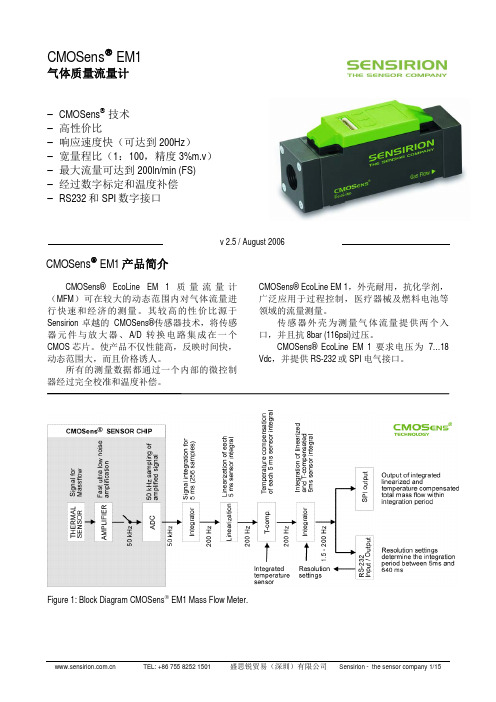
CMOSens EM1 产品简介
CMOSens® EcoLine EM 1 质 量 流 量 计 ( MFM )可在较大的动态范围内对气体流量进 行快速和经济的测量。其较高的性价比源于 Sensirion 卓越的 CMOSens®传感器技术,将传感 器 元 件 与 放 大 器 、 A/D 转 换 电 路 集 成 在 一 个 CMOS 芯片。使产品不仅性能高,反映时间快, 动态范围大,而且价格诱人。 所有的测量数据都通过一个内部的微控制 器经过完全校准和温度补偿。 CMOSens® EcoLine EM 1,外壳耐用,抗化学剂, 广泛应用于过程控制,医疗器械及燃料电池等 领域的流量测量。 传感器外壳为测量气体流量提供两个入 口,并且抗 8bar (116psi)过压。 CMOSens® EcoLine EM 1 要求电压为 7…18 Vdc,并提供 RS-232 或 SPI 电气接口。
单位 °C / °F K K
VDC
最大操作压力 爆破压力 漏率 材料 接触材料
cm / incห้องสมุดไป่ตู้ cm / inch cm / inch g inch bar / psi bar / psi mbar l/s He
1 2 3 4 5
包括偏移,非线性,磁滞 如需要还有更高的精度,可咨询 占满量程(Full Scale)的百分比(FS)
表 3: CMOSens® Ecoline 质量流量计在不同流量水平和积分时间的分辨率(EM 1_V). 流量水平 流量水平 200 ln/min 50 ln/min < 5 ln/min 流量积分时间 13 ln/min 4.0 ln/min 1.0 ln/min 5 ms 3.5 ln/min 1.0 ln/min 0.25 ln/min 20 ms 0.9 ln/min 0.3 ln/min 0.06 ln/min 80 ms 0.11 ln/min 0.03 ln/min 0.0143 ln/min 640 ms 读数频率 200 Hz 读数频率 50 Hz 读数频率 12.5 Hz 读数频率 1.56 Hz
欧姆龙 SMART Sensor Series CMOS 型激光位移传感器 说明书

采用欧姆龙独有HSDR-CMOS (High Speed and Dynamic Range )图像传感器及激光能量的无差异调整算法。
无论金属还是电路板、橡胶、透明体,对于任何颜色及表面状态均可稳定测量。
另外,发射光束也采用线型光束,并对相应的独有受光镜头进行了优化设计。
因此,即使工件处于移动状态,也能实现稳定测量。
超简单设置凭借新的“智能调节”功能,无需依靠使用者的技能,只需一个按钮就能获得实现稳定测量所需的最佳设置。
另外,采用基于测量工件种类、表面状态而选择的3种调节方法,能更加准确地进行设置。
无需操作手册的简单设置智能调节01-8-6-4--2-1-0.8-0.6-0.4-0.200.20.40.60.81246810001-8-6--4-2-1-0.8-0.6-0.4-0.200.20.40.60.81246810-40-30-20-10010203040-400-300-200-1000100200300400CMOS 图像传感器射光元件稳定测量任何颜色、材质的工件使用以往产品检测不同材质时的直线性使用ZX2检测不同材质时的直线性白色陶瓷SUS304镜面加工SUS304拉丝(直交)SUS304拉丝(平行)黑色橡胶距离(mm )距离(mm )直线性(% F S )直线性(% F S )稳定测量移动中的工件工件移动时以往产品的分辨率工件移动时ZX2的分辨率SUS304拉丝(平行)静止状态移动状态误差约400μm误差约7μm工件静止状态移动状态工件测量误差(μm )测量误差(μm )激光能量无差异调整反射率较高的浅色工件…使用低能量激光!反射率较低的深色工件…使用高能量激光!受光元件CMOS 图像传感器3种可选调节方法超稳定测量不受变化的影响动态测量范围100万倍的CMOS环境恶劣时也能放心测量保护结构IP67&机器人电缆单项智能调节确保稳定检测1种工件长按按钮1秒钟,实现最佳设置Scene.11种工件时多重智能调节确保稳定检测多种工件针对各工件长按按钮3秒钟,实现最佳设置Scene.2多种工件混存时动态智能调节确保所有部位均能稳定检测长按按钮5秒钟连续调节,实现最佳设置Scene.3工件的表面不稳定时外形尺寸本机两侧连接器电缆ZX2-XC1R 型ZX2-XC4R 型ZX2-XC9R 型ZX2-XC20R 型传感器探头ZX2-LD50型/ZX2-LD50L 型ZX2-LD100型/ZX2-LD100L 型放大器单元ZX2-LDA11型/ZX2-LDA41型演算单元ZX2-CAL 型CAD 数据29.828.9L 放大器单元连接器(母 6极)传感器探头连接器(公 6极)乙烯绝缘圆形电缆 φ4.7*L 长度如下。
欧姆龙光电传感器选型指南说明书
SELECTION GUIDE According to EN 954-1** The given information is indicative and synthetic; it is compulsory to refer to the complete EN 954 standard for a correct risk and safety type evaluation.TYPE2TYPE41515UNSHIELDEDCABLESSHIELDED CABLESAPPLICATIONSO P E R A T I N G P R O T E C T I O N P O I N TACCESSORIESC O N N E C T O R C A B L E SS E 2-335S F 2-330POWER SUPPLY 24 Vdc 24 Vdc RESOLUTION 35 mm 30 mm OPERATING RANGE 0.2 ... 15 m 0.2 ... 15 m CONTROLLED HEIGHT 150 ... 1650 mm 150 ... 1500 mm RESPONSE TIME 15 ... 32 ms 24 ms max.OUTPUT 2 transistor PNP2 transistor PNPCONNECTION Rx:M12 8-poles; Tx:M12 4-polesRx:M12 5-poles; Tx:M12 4-polesDIMENSIONS 35 x 40 mm31 x 32 mm DEVICE FUNCTIONSTestTestManual/auto reset selection Manual reset Total/partial Muting selection Automatic resetOverrideCERTIFICATIONSAutomatic packaging machinesAutomated assembly lines Automatic working machines Automatic machines for packing and packaging Automatic warehousing and materials handling Automated assembly lines (pick and place)Textile, ceramic, wood and leather industryAccording to IEC 61496-1/ IEC 61496-2C V s e r i e sC S s e r i e sM12 axial and radial connector cables with 3, 4, 8 poles Cable lengths: 3, 5, 10, 15, 25 m Cable material: PVCThe use of shielded cables is compulsory for the safety devices of the SE2and SE4 series, suggested for the Sx -SS T2/ST4M12 axial and radial connector cables with 3, 4, 5 polesCable lengths: 3, 5, 7, 10 m Cable material: PVCM12 4-poles non-cabled connectors are availableAPPLICATIONSO P ER AT IN G P R O T E C T I O N P O I N TS E 4-330S E 4-335POWER SUPPLY24 Vdc 24 Vdc 24 Vdc 24 Vdc RESOLUTION 14 mm 20 mm 30 mm 35 mm OPERATING RANGE 0.2 ... 6 m 0.2 ... 6 m 0.2 ... 15 m 0.2 ... 15 m CONTROLLED HEIGHT 150 ... 900 mm 150 ... 1650 mm 150 ... 1650 mm 150 ... 1650 mm RESPONSE TIME 18 ... 39 ms 16 ... 39 ms 15 ... 32 ms 15 ... 32 ms OUTPUT 2 transistor PNP2 transistor PNP2 transistor PNP2 transistor PNPCONNECTION Rx:M12 8-poles; Tx:M12 4-polesRx:M12 8-poles; Tx:M12 4-polesRx:M12 8-poles; Tx:M12 4-polesRx:M12 8-poles; Tx:M12 4-polesDIMENSIONS 35 x 40 mm 35 x 40 mm 35 x 40 mm 35 x 40 mm DEVICE FUNCTIONSTestTestTestTestManual/auto reset selection Manual/auto reset selection Manual/auto reset selection Manual/auto reset selection Total/partial Muting selectionTotal/partial Muting selectionTotal/partial Muting selectionTotal/partial Muting selectionOverrideOverride Override OverrideCERTIFICATIONSOTHER FUNCTIONS S E 4-114S E 4-220Benders and cuttersMetal, plastic and leather working machinesPresses and punching machinesMetal forming, milling and drilling machinesAccording to IEC 61496-1/IEC 61496-2Presses and punching machinesBenders and cutters Metal working machines COLUMN AND FLOOR STANDSACCESSORIESC O L U M N A ND F L O O R S T A N D S / P R O TE C T I V E S T A N D SPROTECTIVE STANDSS E -S S s e r i e sS E -P P s e r i e sTo be used with the SE2, SE4, SF2safety light curtains series and SE -DD M deviating mirror series Available in different heights:800, 1000 and 1200 mm with 30 x 30 mm profile dimensions1500 and 1800 mm with 45 x 45 mm profile dimensionsGround fixing plate dimensions: 240 x 240 mmTo be used with the SE2, SE4and SF2 safety light curtains series Available in different heights ranging from 273 mm to 1743 mmPRESENCE CONTROL PROTECTION: TYPE 2APPLICATIONSPR ES EN C E C O N T R O L P R O T E C T I O NS F 2-550S F 2-990POWER SUPPLY 24 Vdc 24 Vdc RESOLUTION 50 mm 90 mm OPERATING RANGE 0.2 ... 15 m 0.2 ... 15 m CONTROLLED HEIGHT 300 ... 1500 mm 300 ... 1500 mm RESPONSE TIME 24 ms max.24 ms max.OUTPUT 2 transistor PNP2 transistor PNPCONNECTION Rx:M12 5-poles; Tx:M12 4-polesRx:M12 5-poles; Tx:M12 4-polesDIMENSIONS 31 x 32 mm 31 x 32 mm DEVICE FUNCTIONS TestTestAutomatic resetAutomatic resetCERTIFICATIONSStorage and stacking areasWorking areas Robot areas Robot areas Transfer areas Palletising areasStorage and stacking areasAccording to IEC 61496-1/ IEC 61496-2(pending)(pending)ACCESSORIESF I X I NG B R A C K E T S / S A F E T Y R E L A Y SFIXING BRACKETSSAFETY RELAYSS T s e r i e sS E -S S R 2 s e r i e sThe fixing brackets are supplied together with the safety light curtains of the SE2, SE4 and SF2 seriesStandard fixing brackets (4 pcs kit) are available for the SE2and SE4safety light curtains, as well as orientable, anti-vibration supports and anti-scratch fixing brackets for the SF2 seriesT ype 4 safety relays - safety contacts: 3 NO 1 NCT o be used with the SE2, SE4and SF2safety light curtain seriesPRELIMINARYPRELIMINARYAPPLICATIONSA C C E S S P R O T E C T I O NSB -B B WS-T T 2+Sx -SS T2POWER SUPPLY 24 Vdc24 Vdc N° BEAMS2-3-4up to 2OPERATING RANGE 0.5 ... 50 mup to 50 m CONTROLLED HEIGHT500-800-900-1200 mm 500 mm RESPONSE TIME 14 ms22 ms max.OUTPUT 2 transistor PNP2 relayCONNECTION Rx:M12 8-poles; Tx:M12 4-polesDIMENSIONS 35 x 40 mmDEVICE FUNCTIONSTestTestManual/auto reset selection Manual resetTotal/partial Muting selection OverrideS E 2-P PCERTIFICATIONSAccording to IEC 61496-1/ IEC 61496-2Automatic warehousesRobots Transfer areasPalletisers / depalletisers Automatic warehousesAccess control, working areas and robotsConveyorsSAFETY SENSORS3-pole shielded cable S5/S10-ST2M12 connector – S5/S10/S30-ST2Terminal block – S30-ST2SB-BWS-T2 control unitS5-ST2 M18 plastic safety sensors S10-ST2 M18 metal safety sensors S30-ST2 maxi safety sensorsACCESSORIESD E V I A T I N G M I R R O R S / L A S E R P O I N T E RDEVIATING MIRRORSLASER POINTERS E -D D M s e r i e sS E -L L P s e r i e sT o be used with safety light curtains of the SE2, SE4, SF2series and Sx -S S T2/ST4monobeam safety photosensor seriesAvailable in different heights ranging from 150 mm to 1800 mm Deviating mirrors dimensions: 124 mm width, 6 mm depthTo be used with SE2and SE4 safety light curtain seriesACCESSORIESMUTIN G D E V I C E S /T E S T P I E C E S APPLICATIONSA C C E S S P R O T E C T I O NS E 4-P PSB -B B WS -T T 4+Sx -S S T4POWER SUPPLY 24 Vdc 24 Vdc 24 Vdc N° BEAMS2-3-42-3-42-3-4OPERATING RANGE 0.5 ... 25 m4 ... 50 mup to 50 m CONTROLLED HEIGHT 500-800-900-1200 mm 500-800-900-1200 mm RESPONSE TIME 14 ms14 ms32 ms max.OUTPUT 2 transistor PNP2 transistor PNP2 relayCONNECTION Rx:M12 8-poles; Tx:M12 4-polesRx:M12 8-poles; Tx:M12 4-polesDIMENSIONS 35 x 40 mm 35 x 40 mm DEVICE FUNCTIONSTestTestTestManual/auto reset selection Manual/auto reset selection Manual/auto reset selection Total/partial Muting selection Total/partial Muting selection Total/partial Muting selection OverrideOverrideDouble Muting/OverrideS E 4-Q QCERTIFICATIONSAccording to IEC 61496-1/ IEC 61496-2Assembly robotised linesPalletisers Conveyors Palletisers / depalletisers Automatic warehousesAccess control, working areas and robotsConveyorsSAFETY SENSORS3-pole shielded cable S5/S10-ST4M12 connector – S5/S10/S30/SL5-ST4T erminal block – S30-ST4SB-BWS-T4 control unitS5-ST4 M18 plastic safety sensors S10-ST4 M18 metal safety sensorsSL5-ST4 laser M18plastic safety sensors S30-ST4 maxi safety sensorsMUTING DEVICESTEST PIECESL M S s e r i e sMuting lamps: standard, tower modular, with horizontal and vertical mountingMuting sensors: DATASENSOR non-safety sensors can be used (refer to relative documentation)T P s e r i e sVersions with 14, 20, 30 and 35 mm diameterOTHER FUNCTIONSDATASENSOR SpA is the Italian leading company in the production and sales of optoelectronic devices for detection, safety, measurement and inspection for industrial automation. The range includes complementary products, such as temperature controllers and ultrasonic sensors. The DATASENSOR worldwide presence is guaranteed by the subsidiaries in France, Germany, Spain and UK, as well as a widespread network of local distributors, including selected Qualified Automation Partners (QAPs). Thanks to its unique technology of the product and production process, DATASENSOR can boast an active partnership with the main companies operating in the world of automation.T h e w o r l d w i d e d i s t r i b u t i o n n e t w o r k i s o n -l i n e :w w w .d a t a s e n s o r .c omDATASENSOR SpAvia Lavino 265, 40050 Monte San Pietro, BO - Italy Tel. +39 051/6765611 • Fax +39 051/6759324 •e-mail:*******************DATASENSOR FRANCE Tel. +33 (0)4/72476180Fax +33 (0)4/72470721 e-mail:******************DATASENSOR GmbH Tel. +49 (0)8104/89060Fax +49 (0)8104/890699e-mail:******************。
流量传感器的选择标准要点

流量传感器的选择标准在检测和自动控制系统中,传感器的作用相当于人的五官。
显然,自动化的程度越高,系统对传感器的依赖性也就越大,传感器对系统的功能起着决定性的作用。
因此,国外都将传感器列为尖端技术,尤其在美、日等发达国家,传感器技术更是倍受重视。
更有专家感叹:“征服了传感器,就几乎等于征服了科学技术。
” 传感器的重要性现代信息技术的三大基础是信息的采集、传输和处理技术,即传感器技术、通讯技术和计算机技术,它们分别构成了信息技术系统的“感觉”、“神经”和“大脑”。
信息采集系统的首要部件是传感器,且置于系统的最前端。
仅此而言,传感器也称得上尖端技术。
传感器的选择标准即使对于同种类的被测量物体来说,也可选用各种各样的传感器。
为了选择适合于测量目的的传感器,有必要定出选择的标准。
虽然应该考虑的事项很多,但是,不一定要满足所有事项的要求,随着使用目的的不同,侧重点也会不一样。
例如,需要长时间以及连续使用传感器时,就必须要选择经时变化等时间方面长期稳定性的传感器,而对机械加工或化学分析等时间比较短的工序来说,则要求使用灵敏度和动特性较好的传感器。
此外,还需要考虑与使用传感器有关的事项,以及购买传感器时需要注意的事项等等。
需要注意的事项大致列举如下:与测量条件有关的事项● 测量的目的。
● 被测量的选择● 测量范围● 超标准过大的输入信号的产生次数(产生频度)● 输入信号的频带宽度● 精度要求● 测量所需要的时间与传感器性能有关的事项● 精度● 稳定性● 响应速度● 模拟量与数学量● 输出量及其数量级● 对被物体产生的负载效应● 校正周期● 超标准过大的输入信号保护与使用条件有关的事项● 设置场所● 环境条件(温度、湿度、振动)● 测量时间● 与显示器之间的距离● 与其它设备的连接● 所需功率与购买和维修有关的事项● 价格● 交货日期● 服务与维修制度● 零配件的储备● 保修时间以上是选择传感器时的需要的有关注意事项。
流量传感器的正确选择要点

流量传感器的正确选择有人对美国现场千余台的流量传感器进行了调查,发现其中60%的选择方法不太合适,又大约有一半以上在安装和布局上的问题。
而流量传感器的影响因素比较多,原理有十余种,类型也不少于200种。
那么如何正确选择呢?其实并非易事。
但归纳起来,正确选择流量传感器取决于六个因素:传感器技术参数、流动的状态、流体特性、经济性、、安装、环境。
传感器技术参数总量、流量总量(单位为M3或KG),多用于贸易核算,准确度居于首位。
流量(瞬时量单位为M3/H,KG/H),多用于流程工业,是控制系统的信息源头,重复性是首位。
连续,开关一般流量传感器的输出为连续量,而开关量可用于简单的二位式控制或设备保护,要求可靠性良好。
准确度准确度不仅取决传感器本身,还取决于校验系统,是外加特性。
要说明在什么流量范围内的准确度,如果用于控制系统,还应考虑与整个系统准确度相匹配。
注意:厂家注明的误差是%FS(上限);还是%RD (测值)。
重复性重复性是指环境条件介质参数不变时,对某一流量值多次测量的一致性,是传感器本身的特征。
在流程工业控制系统中,重复性往往比准确度还重要。
不少厂家把重复性误导为准确度,准确度应包括重复性与标定装置的流量不确定度。
量程比在一定准确度范围内,最大与最小流量之比。
差压式流量传感器,从传感器本身可以有较大量程比,但受二次表制约,一般只有3:1。
压力损失流量传感器(除电磁、超声)都有检测件(如孔板、涡轮等),以及强制改变流向(如弯头、科氏)都将产生不可恢复压力损失,它将额外增加输送的动力,才能维持正常运,有些数额很大,在提倡节能的今天应引起重视。
输出信号一般为标准的模拟信号(0~10V,4~20MA等)已不能适应系统发展要求。
通讯要求数字信号,ROSEMOUNT推出了HART协议,RS232/RS485转换器,RS232限于2KM以内,RS485可达10KM。
响应时间输出信号随流量参数变化反应的时间,对控制系统来说,越短越好;对脉动流,则希望有较慢的输出响应。
OMRON D6F-05N7 -02L7 -30A7 MEMS流量传感器 说明书
1:Vcc 2:Vout 3:GND
D6F-30A7-000
流量 L/min(Normal) 输出电压 V 0 1.00 ±0.12 6 2.11 ±0.12 12 3.12 ±0.12 18 3.91 ±0.12 24 4.53 ±0.12 30 5.00 ±0.12
测量条件:电源电压DC12±0.1V、环境温度25±5℃、环境湿度35~75%RH
D6F-05N7/-02L7/-30A7
MEMS流量传感器
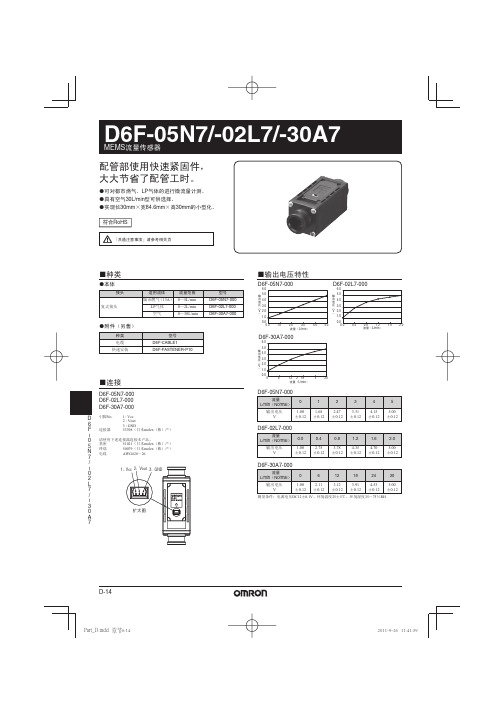
配管部使用快速紧固件, 大大节省了配管工时。
●可对都市燃气、LP气体的进行微流量计测。 ●具有空气30L/min型可供选择。 ●实现长30mm×宽84.6mm×高30mm的小型化。 符合RoHS
「共通注意事项」请参考相关页
■种类
●本体
接头 复式接头 适用流体 LP气体 空气 流量范围 0~2L/min 0~30L/min 型号 D6F-05N7-000 D6F-02L7-000 D6F-30A7-000 城市燃气 (13A) 0~5L/min
引脚No. 1 : Vcc 2 : Vout 3 : GND 53398(日本molex(株)产)
D6F-05N7-000
流量 L/min(Normal) 输出电压 V 0 1.00 ±0.12 1 1.68 ±0.12 2 2.47 ±0.12 3 3.31 ±0.12 4 4.15 ±0.12 5 5.00 ±0.12
MEMS流量传感器
D6F-30A7-000 0~30L/min 空气
2.19kPa
传感器外壁与导线端子间 20MΩ以上(DC500V绝缘电阻) 传感器外壁与导线端子间 AC500V 50/60Hz以上 1分钟(漏电流1mA以下) 72g
- 1、下载文档前请自行甄别文档内容的完整性,平台不提供额外的编辑、内容补充、找答案等附加服务。
- 2、"仅部分预览"的文档,不可在线预览部分如存在完整性等问题,可反馈申请退款(可完整预览的文档不适用该条件!)。
- 3、如文档侵犯您的权益,请联系客服反馈,我们会尽快为您处理(人工客服工作时间:9:00-18:30)。
小型、高精度、耐环境性能卓越的差压传感器
● ±3%RD 的高精度。
● 具备直线补偿、温度补偿功能。
● 数字输出(I2C 通信)。
● 高流量阻抗减少旁路配置的影响。
■种类
符合
RoHS
*1. 适用流体以外的气体种类请向本公司营业人员咨询。
*2. 不含灰尘、油污、油雾等物质的干燥空气*3. 标准大气压(1013.25 hPa)时的压力
■输出电压特性
D6F-PH0025AD1
D6F-PH5050AD3
D6F-PH0505AD3
Ꮒय़˄Pa ˅7000060000500004000030000
2000010000
䕧ߎ5010015020025007000060000500004000030000
2000010000
0ˉ300ˉ100100300500
ˉ500
Ꮒय़ Pa
䕧ߎ7000060000500004000030000
2000010000
0ˉ30ˉ10
103050
ˉ50
Ꮒय़˄Pa ˅
䕧ߎ测量条件:电源电压 DC3.3±0.1V 、环境温度 25±5℃、环境湿度 35~75%RH 差压转换公式:
Dp =(Op -1024)/60000×250Dp :差压Op :输出测量条件:电源电压 DC3.3±0.1V 、环境温度 25±5℃、环境湿度 35~75%RH 差压转换公式:Dp =(Op -1024)/60000×100-50Dp :差压Op :输出
注. 气体密度的变化会影响传感器输出。
大气压的变动按下列公式得到补偿。
Dpeff =Dp ×
(Pstd/Pamb)Dpeff :有效差压Dp :输出差压
Pstd :标准气压(1013.25hPa)Pamb :实际环境下的气压(hPa)
测量条件:电源电压 DC3.3±0.1V 、环境温度 25±5℃、环境湿度 35~75%RH 差压转换公式:Dp =(Op -1024)/60000×100-50Dp :差压Op :输出
D 6F ıP H
压力与流量的关系
■额定值/性能
*1. 标准大气压(1013.25 hPa)时的压力
*2. 不含灰尘、油污、油雾等物质的干燥空气
*3. D6F-PH 基于热对流原理。
测量差压需以空气流通为前提。
流量与差压之间的典型关系即如下所示的特性。
注. 零点精度和满量程精度为独立的误差,并非同时满足。
6040200ˉ20ˉ40
0ˉ300ˉ100100300500
ˉ500
Ꮒय़ Pa
⌕䞣 mL/min
D 6F ıP H
D 6 F ıP
H
■请正确使用
D6F以常规机器中的使用为目的而制造。
尤其是在用于下列对安全性有要求的用途时,应采取失效安全设计、冗余设计并实施定期检查等,在确保系统与设备整体的安全性的前提下使用。
· 以人体保护为目的的安全装置
· 运输设备的控制(行驶停止用途等)
· 航空航天设备
· 核能设备等
不可将D6F
用于其动作直接关乎人命的用途。
应在设备电源切断的状态下进行传感器的设置。
如果在电源接通的状态下进行作业,可能会造成触电和误动作等。
使用注意事项
●关于流体和配管安装、传感器安装
〈共通〉
(1) 应使用清洁的流体。
灰、雾可能会导致特性变化和故障,应
在配管上游侧设置滤网、油雾分离器。
(D6F-W□A1、D6F-V、D6F-P、D6F-PH除外)
(2) 适用流体以外的可燃性气体(氢气等)、腐蚀性气体(氯气、
硫、酸、碱等)是导致故障的原因,请勿使用。
(3) 对于适用流体以外的流体,不属于性能保证范围。
(4) 配管内异物混入是导致故障的原因,从包装袋内取出后,应
防止异物进入配管内。
(5) 配管安装时,注意使流体沿本体上标示的箭头的方向流入。
配管错误的状态下无法正确测量。
(6) 配管建议采取水平的安装方向。
安装方向不水平时,可能会
出现±1%F.S.以上的误差。
(D6F-03A3除外)
(7) 传感器应安装在平面上。
未正确安装时,可能会导致故障或
无法正确测量。
(8) 传感器安装后务必实施动作确认。
(9) 请勿使传感器掉落或对罩盖等进行分解。
〈D6F-PH0025AD1/-PH0505AD3/-PH5050AD3〉
(1) 根据周围环境和安装位置,可能会有尘埃等异物进入传感器
并附着在内部,导致流路部分或全部堵塞。
从而可能会导致传感器无法发挥前述特性,因此采用时应对此有充分的理解,在通过贵公司实际设备进行事前评估的基础上使用。
(2) 配管安装时,请使流体从高压侧流向低压侧。
(3) 安装传感器时,请使用M1.8平头螺丝或具有同等直径的自攻
螺丝,紧固扭矩请设置为0.36N·m以下。
(4) 传感器的输出会受到配管长度的影响。
最长800mm的配管(内径4mm)的误差为1%以下。
(5) 关于连接
·配线时不可搞错端子的极性,否则会导致故障。
·请勿使用DIP焊接(流动焊接)。
·请将产品固定在基板上后进行焊接。
· 焊接条件请使用电烙铁,并设置为加压100gf以下、温度350℃、时间5秒。
(6) 关于使用
· 本产品为精密设备,掉落或受到过度冲击、受力可能会造成故障或特性变化,应避免使其掉落、分解罩盖等或对端子部施加过大的力。
请勿使用掉落过的产品。
·本产品请在得到管理的静电放电保护区域内进行使用。
●关于使用环境
不可在以下环境使用。
·直接承受加热设备的辐射热的场所
·会沾染水分、油污的场所
·阳光直射的场所
·温度变化剧烈的场所
·可能会结冰、凝露的场所
·振动、冲击影响较大的场所
●关于噪声对策
可能会无法正确测量噪声。
使用时请采取以下措施。
· 应尽可能设置在远离产生较强高频的设备(高频焊接器、高频缝纫机等)和产生浪涌电流的机器的地方。
· 应在产生噪声的周边设备(特别是电机、变压器、螺线管、励磁线圈等具有电感成分的物体)上采取浪涌电流吸收器或噪声过滤器等噪声对策措施。
(将配管或导管分离设置、使用屏蔽线等方法也有屏蔽噪声的效果。
)
●关于电源
· 应在确认端子名称与极性的基础上正确配线。
错误配线会导致内部的部件发生故障。
· 使用市售的开关式稳压器时,应对FG(框架接地端子)和G(接地端子)进行接地。
关于RoHS指令
停止使用6种RoHS限制物质的产品(包括工序内以及电路板上搭载的电子部件)的包装上标示有RoHS标志。
※由于供应商的原因,已经作为符合RoHS的零部件如被判断为不符合RoHS 的产品等时,不得已会将标志取消。
●RoHS符合判断基准
RoHS指令6种物质的符合判断使用以下基准。
(RoHS指令适用豁免项目除外)
·铅:1000ppm以下·六价铬:1000ppm以下
·汞:1000ppm以下·PBB :1000ppm以下
·镉:100ppm以下·PBDE :1000ppm以下
D 6 F ıP H。