爱华aiwa-NSX-990操作手册121
KN-990短波电台操作说明书(V3版)
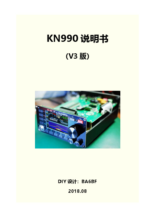
KN990说明书(V3版)DIY设计:BA6BF2018.08目录一、前后面板介绍 (1)二、开关机 (2)三、界面简介 (2)四、工作频率(VFO) (2)五、调制模式 (3)六、菜单 (3)6.1. 界面 (4)6.2. 表选择 (4)6.3. 调制模式 (4)6.4. 上下边带 (4)6.5. 旋钮功能 (4)6.6. VFO/存储模式 (5)6.7. 免提 (5)6.8. BK-IN (5)6.9. 高放 (5)6.10. 自动天调 (6)6.11. 增量 (6)6.12. 异频 (6)七、副屏 (6)八、CAT 计算机辅助控制系统 (10)九、USB (11)十、系统设置 (11)10.1. 发射设置 (11)10.2. 电报 (12)10.3. 调频 (13)10.4. 系统 (13)10.5. 红白机 (15)10.6. 语言 (16)10.7. 关于 (16)十一、固件升级 (16)十二、截图 (22)十三、VFO范围限制 (22)KN990简介:KN990是BA6BF于2018年6月开发推出的一款采用中频DSP技术的短波全段全模式收发信机,4吋彩色液晶屏、全中文菜单,并带实时频谱显示(频谱刷新率达到30帧/秒,已远优于很多商业电台)。
其基本技术指标和广受好评的KN850类似,并因为采用了数字中频技术得到了一些不太一样的操作体验。
又因自带游戏模拟器,能让HAM们在CQ之余娱乐一把经典老游戏,因此还被HAM们戏称为业余收发信机中最好的游戏机。
KN990主要参数:频率范围:接收: 0.1~30MHz发射: 业余短波波段工作模式:SSB/CW/AM/FM/DIGITAL接收灵敏度:0.2uV最小频率步进:10Hz工作电压:12~15V DC电流参数:接收0.4A发射4A @Max整机尺寸: 160X80X220(mm)[不包括突出物]发射功率:额定15瓦调制方式:全部模式均数字调制及解调杂散抑制度:≥45dBc载波抑制:≥45dBc选择性:全部模式带宽均连续可调(最小带宽调整步进为10Hz)KN990说明书(V3版)一、前后面板介绍注意:U盘只有插在USB2口时才能正常工作二、开关机1. 开机:接通电源,点击电源键即可2. 关机:按住电源键,保持1秒左右即可关机3. 注意:开机之后对电台所有设置的修改,只会在长按电源键关机时保存,如果直接切断电源,那么断电前的修改都不会保存(录音是实时保存的,是个例外)三、界面简介1. 界面左边4个按钮称为“菜单”,分别对应前面板4个实体“菜单键”2. 界面下半部分称为“副屏”3. 副屏下方显示5个“副屏按钮”,分别对应前面板5个实体“副屏按钮”四、工作频率(VFO)1. 修改VFO:转动主旋钮,VFO范围:0-150M2. 修改步进:点击电源键并转动主旋钮3. 修改步进时可以直接在VFOA和VFOB之间切换4. 默认状态下,VFOA既是接收频率也是发射频率,当启用“异频”时,VFOA是接收频率,VFOB是发射频率五、调制模式1. 一共有SSB,CW,AM,FM,WFM五种调制模式2. 切换调制模式:点击菜单“调制模式切换”3. 切换边带:点击菜单按钮“上下边带”4. 边带设置有3种类型:上边带:强制上边带下边带:强制下边带自动:VFO<10M时下边带,VFO>=10M时上边带六、菜单菜单一共3页,使用前面板的DIS键切换6.1. 界面循环切换副屏,副屏会下文详细说明6.2. 表选择接收表有两个:“信号强度”和“音量表”发射表也是两个:“发射功率”和“驻波比”只有在发射时才能切换发射表!6.3. 调制模式循环切换SSB,CW,AM,FM,WFM五种调制模式其中SSB和CW会在不同边带时显示USB,LSB,CW,CWR6.4. 上下边带循环切换“上边带”,“下边带”,“自动”6.5. 旋钮功能指定前面板“多功能旋钮”当前正在设置哪个参数不使用:多功能旋钮不设置任何参数发射功率:1~15W发射功率发报速度:CW模式时自动键的发报速度,4~60wpm带宽:接收带宽,不同调制模式有不同的带宽范围,甚至是带宽不可调偏移:接收偏移,不同调制模式有不同的偏移范围,甚至是偏移不可调增量:下文会详细介绍,增量范围-9.99kHz~+9.99kHzVOX灵敏:免提(VOX)功能的灵敏度,1%~100%FM灵敏:FM静噪灵敏度,1%~100%WFM灵敏:WFM静噪灵敏度,1%~100%6.6. VFO/存储模式循环切换VFO模式,存储模式VFO模式:有2套工作参数(VFOA,VFOB),包括频率,调制模式,接收带宽,接收偏移,这些参数随时可以修改,关机时都会自动保存存储模式:有99套工作参数(MEMO1~MEMO99),包括频率,调制模式,接收带宽,接收偏移,这些参数随时可以修改,但是仅在存储列表界面使用“保存”按钮才可以保存存储模式相当于“收藏夹”功能,帮助用户记录一些喜欢的频点和它的调制模式用户甚至可以给存储的频道设置名称6.7. 免提也叫VOX,开启后将会根据音频输入的声音大小来自动进入发射状态,VOX的灵敏度和发射延迟均可以调整(下文会介绍)6.8. BK-INCW发射延迟默认为关闭状态,开启后将会关闭CW的发射延迟6.9. 高放将接收信号放大100倍6.10. 自动天调需配合KT系列自动天调使用点击后将会以当前VFO,CW模式,3W发射功率开始发射并通知自动天调开始工作自动天调完成调整后自动关闭发射6.11. 增量增量分为接收增量和发射增量两种接收增量和传统电台的“RIT”功能类似发射增量和传统电台的“⊿TX”功能类似此功能主要在发现对面电台频率不准确时使用接收增量和发射增量不可同时开启接收增量开启时,实际接收频率=VFO+增量值,发射频率不变发射增量开启时,实际发射频率=VFO+增量值,接收频率不变增量值范围:-9.99kHz~+9.99kHz6.12. 异频也叫Split,开启后VFOA将作为接收频率,VFOB将作为发射频率异频功能可以使接收和发射工作在完全不同的频段上,而增量只有±9.99k的偏移范围七、副屏1. 切换副屏:点击菜单“界面”2. 每个副屏都有对应的5个副屏按钮,大多为当前副屏相关的操作上:VFO模式时切换波段,存储模式时切换存储频道下:和"上"键功能相同,切换方向相反显示方式:大瀑布/小瀑布切换中心红色竖线表示当前VFO位置相邻两根竖线间隔为10kHz竖线上方会显示该处频率(精确到10kHz),当该处频率>=100M时不显示信号高度会自动适应屏幕高度,以避免强信号溢出屏幕范围,或者弱信号难以观察,所以频谱显示的高度并不代表绝对信号强度,而是当前频谱范围内所有信号的相对信号强度上:VFO模式时切换波段,存储模式时切换存储频道下:和"上"键功能相同,切换方向相反相邻竖线间隔为1kHz设置带宽:进入编辑带宽模式,主旋钮调整带宽,再次点击退出编辑带宽模式偏移:进入编辑偏移模式,主旋钮调整偏移,再次点击退出编辑偏移模式恢复默认:将当前滤波器参数恢复到默认参数发射/接收:切换发射滤波器和接收滤波器形状:切换带通图形显示的形状,分为锐利和柔和两种带宽和偏移的步进均为10Hz所有调制模式的滤波器参数都是独立的,互不影响所有调制模式的发射和接收滤波器也是独立的,互不影响不同调制模式会有不同的带通图形带通图形中白色竖线表示VFO位置,黑色竖线表示带通中心带通图形下方的白色数字表示带通范围的左右边界频率,黄色数字表示带通中心频率特别注意:SSB模式中发射偏移默认为300Hz,设置太低的话发射时会有载波泄漏的情况上:VFO模式时切换波段,存储模式时切换存储频道下:和"上"键功能相同,切换方向相反解码功能目前仅支持CW解码,需要使用CW模式(边带无关)界面上方显示点画信息,下方显示解码字符解码正确率依赖稳定的信号强度,标准的发报手法上:切换存储频道下:和"上"键功能相同,切换方向相反保存:将当前工作频率,调制模式,接收带宽,接收偏移,存储到当前选中的频道中清空:将当前选中的频道清除设置名称:进入编辑频道名称模式,大旋钮修改字符,上下键移动光标,再次点击退出编辑频道名称模式菜单“VFO/存储模式”可以切换到存储模式,此时将使用当前频道信息做为工作参数(包括工作频率,调制模式,接收带宽,接收偏移)最多可以保存99个频道只有当副屏停留在存储列表时,才可以切换到空白的频道上,当副屏在频谱界面并且当前处于存储模式时,点击上下键只会在非空白的频道中循环切换未设置名称的频道会显示MEMO+n,否则显示设置的名称操作:在发射模式/播放模式/录音模式中循环切换T1:发射模式->发射T1录音内容进行循环发射(发射时本机喇叭不会播放录音内容);播放模式->本机喇叭循环播放T1录音内容,但是不会发射;录音模式->清空旧的录音并准备开始新的录音,手咪的PTT键被按住时才会录音,当PTT键松开时录音会暂停T2:和T1功能相同,但是操作的是T2录音间隔:发射模式和播放模式的循环间隔,在发射模式中,只有发射录音时机器才会处于发射状态,在间隔时间里,机器处于接收状态,会正常解调声音最多支持T1和T2两条录音,每条录音最多可以录约15.977秒界面会以图形方式显示录音预览,线条的高矮表示声音的大小上:向上移动光标下:向下移动光标确定:进入选择的项目或开始编辑值,绝大部分编辑都是使用大旋钮调整值,上下键移动光标(如果光标可以移动的话)返回:返回上一层所有设置选项的解释会在下文详细说明八、CAT 计算机辅助控制系统KN990的CAT协议与Yaesu FT817兼容也就是说支持FT817的CAT软件都可以用来操作KN990,例如“Ham Radio Deluxe”接口:机器背部的方口USB(USB-B型,打印机USB口)波特率:38400九、USBKN990目前支持U盘,键盘,游戏手柄,三种USB设备机器背部提供了两个可以同时工作的USB口,但是注意U盘只有插在USB2时才能正常工作,其他设备两个口都支持当插入的USB设备被正常识别后界面会显示图标当插入的USB设备没有正常识别时会显示如下图标目前USB驱动并不太稳定,可能会出现有时能识别有时不能识别的情况,如果反复插拔依然不识别的话可以重启一下机器,一般都能解决十、系统设置系统设置有多级菜单,每个选项的名称后面带有“>”符号的表示这里是进入下一级菜单的入口,例如:10.1. 发射设置发射功率:1~15W,步进1W练习模式(不发射):开启此选项后除了自动天调以外,其他任何情况都不会发射,此选项和电报设置中的练习模式是联动的(相当于同一个选项,在两个菜单都有显示)免提灵敏度:也称为VOX灵敏度,开启免提时生效,此选项控制多大的输入音量可以触发免提发射关闭发射延迟:此选项同时控制免提和电报在发射完毕后等待多久关闭发射,此选项和电报设置中的关闭发射延迟是联动的(相当于同一个选项,在两个菜单都有显示)高驻波保护模式:关断模式->当驻波大于等于阈值时关闭发射,同时关闭自动天调和免提;降功率模式->当驻波大于阈值时开始逐渐降低实际发射功率,当驻波-阈值大于1后,实际发射功率降低到3W并不再继续降低高驻波保护阈值:控制触发高驻波保护的阀门值10.2. 电报键模式:手键->单键发报,按下时发射侧音,放开停止;自动键->双键发报,点键按下连续发点,画键按下连续发画,自动产生标准点画间隔;KN990的自动键模式和FT817相同,属于压一键模式练习模式(不发射):开启此选项后除了自动天调以外,其他任何情况都不会发射,此选项和发射设置中的练习模式是联动的(相当于同一个选项,在两个菜单都有显示)发报速度:自动键的发报速度,4~60wpm,步进1wpm侧音音调:同时控制发射时的本地侧音音调,和接收时的侧音音调,300~1200Hz,步进50Hz侧音音量:控制发射时的本地侧音音量,0%~100%双键反转:对调自动键的点画按键选择:电子键->使用机器背面的电键插口发报;话筒键->使用话筒的加减键发报关闭发射延迟:此选项同时控制免提和电报在发射完毕后等待多久关闭发射,此选项和发射设置中的关闭发射延迟是联动的(相当于同一个选项,在两个菜单都有显示)10.3. 调频FM静噪灵敏度:1%~100%,控制FM模式时信号强度低于多少时开始静音WFM静噪灵敏度:1%~100%,控制WFM模式时信号强度低于多少时开始静音10.4. 系统时间日期:进入时间日期设置菜单,这个菜单很好理解就不做说明了,注意:设置的时间和时区是本地时间本地时区,UTC时间将根据设置的本地时区计算配置:导出到U盘:将本机所有的用户配置和出厂前的校准参数导出到U盘根目录“config.rtf”文件,请所有用户务必在收到机器后导出一次配置并且将配置文件妥善保留起来,让机器在出现一些不可预知的意外情况后可以自行恢复到出厂状态(这种情况几乎不可能出现,但是留个保险总是好的)从U盘导入:U盘根目录“config.rtf”文件并将其中的所有配置应用到本机,请不要导入其他机器的配置,因为配置里包含的出厂前的校准参数,每台机器都是不一样的恢复出厂:恢复所有用户配置到出厂状态,出厂前的校准参数不会恢复注意:仅支持FAT或FAT32格式的U盘,如果您的U盘不是这个格式(比如NTFS),使用Windows将U盘格式化到FAT32格式即可U盘只有在插入机器背面的USB2口才能正常使用,如果插在USB1口,可以识别为U盘,但是不能读写文件频率校准:如果您认为本机的工作频率不准确,可以在这里进行校准,校准范围±10kHz,上下键控制步进,大旋钮调整值机器名:修改主界面正上方显示的机器名,此名称同样会显示在开机画面中开机画面:炫酷的黑客帝国字符雨开机画面,可以选择完整/简洁/关闭3种方式关机画面:模拟老电视的关机效果,可以选择开启/关闭2种方式电源电压调整:如果您认为机器显示的电源电压并不准确,可以在这里用大旋钮输入您测量到的实际电压,然后按确定键即可升级:升级固件用,下文将详细说明10.5. 红白机超级玛丽:点击确定进入超级玛丽游戏魂斗罗:点击确定进入魂斗罗游戏键盘设置:设置USB键盘的游戏键位手柄设置:设置USB手柄的游戏键位目前仅支持两个内置的红白机游戏,未来会支持从U盘自由导入游戏目前只有键盘可以实现双人同时游戏,手柄仅支持单人KN990支持标准USB接口的HID协议手柄,如果您不确定应该选择哪一款,可以直接选购下面链接中的手柄:https:///item.htm?id=39333429326&spm=a1z09.2.0.0.59cb2e8 dqNTkGu&_u=735ehb1816b10.6. 语言语言:切换显示语言,支持简体中文和英语两种10.7. 关于版本号:本机固件的版本号硬件:BA6BF,硬件作者软件:Droid Zhang,软件作者说明书:显示本说明书的二维码,扫一扫就可以看到本说明了更新日志:显示更新日志的二维码,扫一扫就可以看到所有版本的更新内容了十一、固件升级准备工作:1. 准备一台可以上网的Windows系统的电脑2. 下载升级工具“KN990升级工具”网页下载/kn/kn990/KN990升级工具V2.exe QQ群共享下载:群号1243210523. 准备一条方口USB线(USB-B型,打印机USB线)4.准备一个U盘升级步骤:1. 电台进入设置->系统设置->配置->导出到U盘因为升级固件会强制恢复出厂一次,所以为了避免以前的设置丢失,必须手动导出配置2. 运行升级工具并等待自动获取到最新版本3. 使用方口USB线连接电台和电脑,并选择好串口号如果找不到电台的串口号,可以在Windows的设备管理器里检查一下是否是因为没有安装CH340驱动,驱动程序在群文件里有很多用户上传了,可以都试一下如果一切正常的话,升级工具界面上会显示绿色方形4. 电台进入设置->系统设置->升级此时升级工具界面就可以获取到电台的本机版本号了5 .点击升级工具的“开始升级”按钮,稍等片刻,升级工具和电台的进度条都开始走动6.升级完成后电台自动重启并强制恢复出厂,进入设置->系统设置->配置->从U盘导入,升级完成升级失败:如果因为断电,USB接触不良,电脑死机等意外情况导致升级过程中断,那么电台将无法正常开机(变砖),也无法按照上面的步骤重新开始升级,此时请按照如下步骤救机:1. 切断电台电源,强制关机2. 关闭升级工具重新打开3. 插上电台电源,使用方口USB线连接电台和电脑4. 按住电台前面板下方副屏按钮的右边最后一个键不放(下图,蓝圈所示),同时快速的点击一下电源键(注意是快速点击,不要按住,也不要按太久)此时电台会强制进入一个引导程序,并且界面显示如下:5. 升级工具选择串口号6. 如果串口号选择好之后读取到了电台固件版本且显示了绿色方形表示连接成功,然后点击开始升级即可,如果没有正常读取到电台固件,请回到步骤1重新开始7. 开始升级后耐心等待进度条走完即可注意:正常的升级过程无论发生什么意外都可以使用上面的步骤救机,永不变砖,所以请放行升级,不用担心十二、截图KN990提供界面截图功能1. 将U盘插入机器背面USB2口2.将USB键盘插入机器背面USB1口3. 按键盘PrtSc键(这个键一般在F12的右边)4. 截图需要几秒钟时间,期间电台界面会暂停刷新,截图完成后界面恢复刷新,并提示“完成”,截图文件保存在U盘根目录“kn990.bmp”注意:目前截到的图是上下颠倒的,可以使用Windows自带的画图工具全选(Ctrl+A)再垂直翻转一下即可使用,截图的颜色和电台的实际显示颜色会有色差十三、VFO范围限制KN990默认VFO范围为0~150M,为了一些特殊需求,提供了一个隐藏开关可以将VFO范围限制到3~30M1. 将VFO频率调整为12.345.672. 按住电源键关机3. 按电源键开机4. 此时VFO范围已变成3~30M如果想恢复到之前的VFO范围,再次执行以上步骤即可附录:KN990面板尺寸最新说明书固件更新日志。
胜利仪器 VICTOR 9000A蓝牙版高低压钳形电流表 说明书

目录注意 (1)一.简介 (2)二.电气符号 (2)三.主要技术参数 (2)四.技术规格 (3)五.结构 (4)六.液晶显示 (5)1.液晶显示屏 (5)2.特殊符号说明 (5)3.显示示例 (5)七.操作方法 (6)(一)检测仪操作 (6)1.开关机 (6)2.通常测试 (7)3.PEAK测试 (8)4.蓝牙测试 (9)5.数据保持 (9)6.数据存储 (9)7.数据查阅 (9)8.数据清除 (9)(二)蓝牙软件操作 (10)1.软件介绍 (10)2.APP软件安装 (10)3.软件使用 (10)4.软件卸载 (11)九.装箱单 (11)注意感谢您购买了本公司的VICTOR9000A蓝牙版高低压钳形电流表,为了更好地使用本产品,请一定:——详细阅读本用户手册,操作者必须完全理解手册说明并能熟练操作本仪表后才能进行现场测试。
——严格遵守本手册所列出的安全规则及注意事项。
◆任何情况下,使用本仪表应特别注意安全,尤其测量超过AC100V及以上电压线路的时候。
◆若被测线路电压超过600V必须连接绝缘杆使用。
◆由于高压线路很危险,操作者必须经严格培训并获得国家相关高压操作认证才能使用本仪表进行现场测试。
◆严禁用本仪表测试电压超过110kV的裸导线或汇流母线。
◆注意本仪表面板及背板的标贴文字及符号。
◆请勿于高温潮湿,有结露的场所及日光直射下长时间放置和存放仪表。
◆更换电池,请注意电池极性,长时间不用本仪表,请取出电池。
◆拆卸、维修本仪表,必须由有授权资格的人员操作。
◆若本仪表的钳头及其他部件有损伤,请禁止使用。
◆避免冲击钳头,定期保养本仪表,不能用腐蚀剂或粗糙物清洁,须用软布(如眼镜布),沾清洁防锈除湿类的润滑剂(如WD-40),轻轻擦拭仪表钳头即可。
◆由于本仪表原因,继续使用会带来危险时,应立即停止使用,并马上封存,◆◆操作。
◆建议本仪表每年至少进行一次绝缘强度测试(AC110kV/rms5节绝缘杆完全连接,两端之间)。
AIWA CSD快速手册
AIWA CSD-ES50手提音响使用指南(快速上手)
特奥淘宝店
1、注意事项
◆请确认所用市电为正常范围
◆如用电池,忽略上步骤
◆如果本机从室外带至室内(冷处至温暖处),可能会造成部件结露现象,请稍等片刻◆机器顶部为CD舱,打开后,可见到激光头,此部件为敏感易损部件,勿触。
2、操作步骤
2.1 开机
将电源线从机器背部电池仓中取出,一端接机器(插口也在背部),一端接220V交流电插座
此时,手提音响处于待机/卡带播放,状态,如果要放卡带,按下相应按键,即可播放。
2.2 CD收听
如下图所示,轻按顶部CD舱盖右前部(有防滑触点),舱门即可弹起,将所要播放CD碟放入后,重新关上CD舱盖。
将下图所示FUNCTION波段,拨至CD档(即最右端),可以看到,液晶显示,CD碟开始读取,会显示出总曲目等相关信息,此时可以按PLAY等微触键进行操作
最左侧为耳机插孔,用来独享音乐。
2.3 收音机
FUNCTION波段,拨至RADIO档(即中间),右侧有BAND波段开关可以选择电台波段,MW为中波,SW为短波,FM为调频,选择相应波段,(SW,FM收听,需要将拉杆天线抽出),调节TURNING,选出相应电台欣赏。
2.4 磁带收听
将FUNCTION波段,拨至TAPE档,可对各仓卡带进行对应操作。
注:音响断开市电前,最好将波段拨至TAPE档(待机状态)。
2.5 音效及其他按键
FM STEREO 指示:当收听调频节目为立体声信号时,此灯亮起
下面黑色按键,可供用户选择各种音效,如增加低音,增加环绕效果。
感谢选择特奥淘宝店
祝:一切顺利
Ups专家。
L9901智能电力参数综合测试仪操作手册

L9901智能电力参数综合测试仪操作手册12L9901智能电力参数综合测试仪使用说明书要新占保定市力兴电子设备有限公司重要提示:1、仪器在不使用的情况下,请及时关闭电源!2、充电电池属于消耗部件,应注意维护,在使用时充电电池有效容量会随时间逐渐降低,从而使有效使用时间缩短,为了尽量提高电池寿命,请注意以下维护措施:●如果长期不使用仪器,请定期进行充电,电池应至少每月充电一次;●严禁亏电使用,亏电将严重缩短电池寿命,甚至使电池报废,当仪器欠电时,应马上关闭电源,进行充电。
避免因电池放电时间过长而导致电池失效。
3、指示灯说明:功能灯:输出过流时,功能灯亮红色并闪烁;电流输出过程中严重欠电时,功能灯亮蓝色。
充电灯:充电过程中亮红色;充电完成后亮绿色。
目录一、概述 (3)二、主要功能与特点 (3)三、主要技术指标 (4)四、面板及各键功能介绍 (4)五、变压器容量、空载、负载、零序阻抗测试及菜单操作方法 (5)六、注意事项 (21)七、售后服务 (21)八、附录 (22)一、概述:L9901智能电力参数综合测试仪,是专用于配电电力变压器容量测量、变压器空载及短路损耗测量的仪器。
该仪器电路设计精巧,思路独特,仪器内部采用先进的六路同步交流采样及数字信号处理技术,成功的解决了低功率因数测量及多路信号在市电条件下同步测量和计算的难题。
线电压采集引入角度,而非传统的乘固定系数,从而能够真实反映变压器试品的真实电压。
同时仪器测量引入了必要的校正(如: 电压校正、电流校正、温度校正、频率校正)。
从而使其性能优越,功能强大,体积小,重量轻,操作简单方便,数据准确可靠,可完全取代传统仪表的测试方法,可显示并记录用户关心的所有测量数据,可作为现场高精度交流指示仪表使用。
使用该仪器可大大提高工作效率,减轻劳动强度。
二、主要功能与特点:1. 容量的测量:仪器内置可充电电池,仪器本身可输出三相正弦波逆变电源,无需任何外部电源可实现配电变压器容量的测量和型号的判断,同时显示变压器阻抗电压和折算到额定温度、额定电流下的负载损耗。
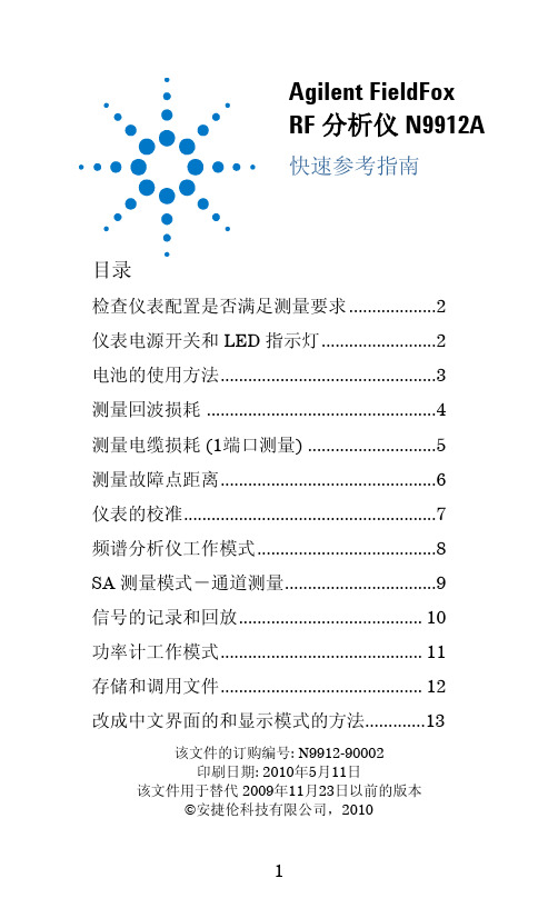
Agilent FieldFox RF 分析仪 N9912A 快速参考指南
仪表电源开关和 LED 指示灯
按下仪表面板上的电源开关即可打开 N9912A,指示 N9912A 电源已打开的发光二极管会变为绿色,仪表的启 动时间大约为 60 秒。 如果想让仪表工作在 待机 状态(对电池的电量消耗很低), 只需要短促地按一下电源开关即可,LED 指示灯的颜色变 为琥珀色,并很慢地闪烁。在开机时,只要再短促地按下 电源开关,仪表即可回到原先的设定状态。 如果要把仪表彻底关机(对电池电量的消耗极低),需要 长久按住电源开关,持续到仪表彻底关机为止(大概为 4 秒钟)。仪表彻底关机后,LED 指示灯也随机关闭。
7
频谱分析仪(SA)工作模式
频谱分析仪工作模式不需要对仪表进行校准。 检查测量结果是否被压缩的方法: 1. 使用一个游标,并把该游标放在信号的峰值处,记录 此时峰值信号功率的大小。 2. 把内置射频衰减器的衰减量增加 5 dB。 如果测量到的信号的功率没有变化,那么就证明没有 压缩现象出现,这表明被测信号是在测量接收机的线 性区域内。 如果测量到的信号的功率因为衰减量提高 5 dB 而增 大了,那么就证明确实有压缩现象存在。然后把衰减 量设置到再继续增加衰减量将不会产生被测量到的信 号的功率会继续提高的现象的值 。 设定射频衰减值 1. 按 Preset 键,然后选择 Preset 2. 按 Mode 键,然后选择 SA 3. 按 Scale/Amptd 键,然后选择 RF Atten Auto 表示对射频信号的衰减量是由仪表自动设置的, 调节 N9912A 的参考电平就会自动调节衰减量。 Man 表示对射频信号的衰减量是靠手动来调节的。 在 SA 测量模式下可以显示四种类型的测量轨迹 对 N9912A SA 测量模式的设置适用于所有轨迹的显示 1. 按 Trace 6 键,然后通过 Trace 1,2,3,4 选择要显 示的测量轨迹 2. 然后用 State 选择轨迹的类型
990-0375G 12 2006 BroadBand PowerShield 用户手册说明书

990-0375G 12/2006BroadBandPowerShield ®User ManualChapter 1 General InformationThe PowerShield® provides a power source for broadband telephony and other DC applications. SafetyThis Safety Guide contains important instructions that should be followed during installation and maintenance of the APC equipment and batteries. It is intended for APC customers who setup, install, relocate, or maintain APC equipment.Changes and modifications to this unit not expressly approved by APC could void the warranty.Failure to observe these warnings may result in serious injury, death or damage to the equipment.Electrical Warnings Do not work alone under hazardous conditions.Servicing this equipment may require working with protective covers removed and utility power connected. Use extreme caution during these procedures. Check that the power cord(s), plug(s), and sockets are in good condition. Replacement of fuses or other parts must be with identical types and ratings. Substitution of nonidentical parts may cause safety and fire hazards.Battery Warnings Danger of explosion if battery is incorrectly connected or replaced. Use only APC replacement batteries.1SpecificationsModel Number Input OutputMaxSignalVoltageMaxSignalCurrentBattery typeSame for All ModelsCP15U48 100-240V 50-60Hz 1.0A 48V15W30V 5mA CP24U12 100-240V 50-60Hz 1.0A 12V24W30V 5mACP40U48 100-240V 50-60Hz 1.5A 48V40W 30V 5mA12V 7.2AHrSpill-Proof,Maintenance-Free,Sealed Lead AcidEnvironmental SpecificationsOperating Temperature 32º F to 113º F (0º C to 45º C)Operating Humidity 0 to 95% noncondensing within enclosureMax Operating Elevation 10,000 ft (3,000 m)Max Storage Elevation 50,000 ft (15,000 m)Storage Temperature -5º F to 113º F (-15º C to 45º C)Physical SpecificationsCharacteristic Specification Height x Width x DepthUPSUPS carton 7.5 x 9.5 x 3 in (19 x 24 x 7.6 cm) 13.5 x 13.5 x 4.5 in (34 x 34 x 11 cm)WeightUPSUPS with package materials 7.5 lbs (3 kg) 9 lbs (4 kg)UnpackingInspect the unit upon receipt. Notify the shipping carrier or product supplier if there is damage.The packaging is recyclable; save it for reuse or dispose of it properly.Check the package contents. The package contains the enclosure, the battery (to be installed), onepower cord, one seven-pin output connector, and product documentation.23Chapter 2 InstallationEnclosure InstallationInstall the UPS in a protected area that is free of excessive dust and has adequate airflow. Do not operate the power supply where the temperature and humidity are outside thespecified limits. Refer to Specifications in this manual.Install the UPS inside a building in a protected area that is free of excessive dust and has adequate airflow.Use screws that are appropriate for the weight of this unit and the mounting surface material. Refer to Specifications in this manual.Step 1Step 2Step 3Battery Cover Release Tabs4Battery InstallationBattery ReplacementThis UPS has an easy to replace, hot-swappable battery. Replacement is a safe procedure, isolated from electrical hazards. You may leave the UPS and connected equipment on for this procedure. Replace the spent battery with replacement battery RBC40. See your dealer or refer to the APC Web site, for information on replacement battery modules. To replace the battery module refer to Battery Installation, above.Once the battery is disconnected, the connected equipment is not protected from power outages.Be sure to deliver spent batteries to a recycling facility found on the Used Battery Return Facilities list included with the unit.Step 2Step 3Step 1Red CableBlack CablePositive TerminalBattery Cover Release TabsNegative Terminal5Chapter 3 OperationConnect Equipment and PowerThe UPS battery charges when it is connected to utility power. The battery charges fully during the first eight hours of normal operation.Do not expect full battery run capability during this initial charge period.1. Connect equipment to the UPS communication signals via the seven-pin connector (included), oruse an APC custom data cable, (must be ordered separately). 2. Plug the UPS power cord into the utility power cord inlet and then into the wall outlet.NOTE: DO NOT overload the wall outlet or circuit. Utility Power Cord InletCold StartCommunication Signals6Status IndicatorsUPS Front ViewGreen indicates the UPS is on utility power. Yellow indicates the UPS is on battery power.Green indicates DC output power is provided by the battery or utility power. Red indicates that the battery is not connected or the battery needs to be replaced. Refer to the Battery Replacement section.Communication SignalsThe PowerShield communication signals are isolated from its internal circuitry via open collector opto-coupled transistors. The connection labeled “Signal Return” is a common return point for all communication signals. In the typical application, the attached equipment digital ground connects to Signal Return, and pull-up resistors turn the open collector signals into logic levels.+Voltage output Voltage output Signal return.Low when operating from utility line. Open when operating from battery.Low when battery is charged. Open when battery fails the Self Test. Low when battery is present. Open when battery is missing.Low when battery is near full charge capacity. Open when operating from a battery with < 20% capacity.Cold StartUse the cold start feature to apply power to the UPS and connected equipment when the UPS is off and there is no utility power. The battery must be charged for the cold start feature to work. To utilize the cold start feature, use a small pointed object to press the recessed cold start button.Status Indicators78Chapter 4 Service, Contact and Warranty InformationServiceAPC makes every effort to ensure parts and equipment arrive in working condition. Occasionally, it may be necessary to return parts or equipment that are not in working condition. If the UPS requires service, follow these steps:1. Contact APC Customer Support through the APC Web site, .Note the product model number, the serial number, and the date purchased. If you call APC Customer Support, a technician will ask you to describe the problem and try to solve it over the phone. If this is not possible the technician will issue a Returned Material Authorization Number (RMA#).If the product is under warranty, repairs are free. If not, there is a repair charge.Procedures for servicing or returning products may vary internationally. Refer to the APC Web site. Select the appropriate country from the country selection field. Select Support from the tab at the top of the web page.2. Pack the product in its original packaging.Pack the unit properly to avoid damage in transit. Never use Styrofoam beads for packaging. Damage sustained in transit is not covered under warranty.3. Mark the RMA# on the outside of the package.4.Return the unit by insured, prepaid carrier to the address given to you by Customer Support.Always DISCONNECT THE BATTERY before shipping in compliance with U.S. Department of Transportation (DOT) regulations.How to Contact APCRefer to the APC Web site, .9Limited WarrantyAmerican Power Conversion (APC) warrants its products to be free from defects in materials and workmanship for a period oftwo years from the date of purchase. Its obligation under this warranty is limited to repairing or replacing, at its own soleoption, any such defective products. To obtain service under warranty you must obtain a Returned Material Authorization(RMA) number from customer support. Products must be returned with transportation charges prepaid and must beaccompanied by a brief description of the problem encountered and proof of date and place of purchase. This warranty doesnot apply to equipment that has been damaged by accident, negligence, or misapplication or has been altered or modified inany way. This warranty applies only to the original purchaser who must have properly registered the product within 10 days ofpurchase.EXCEPT AS PROVIDED HEREIN, AMERICAN POWER CONVERSION MAKES NO WARRANTIES, EXPRESSED ORIMPLIED, INCLUDING WARRANTIES OF MERCHANTABILITY AND FITNESS FOR A PARTICULAR PURPOSE.Some states do not permit limitation or exclusion of implied warranties; therefore, the aforesaid limitation(s) or exclusion(s)may not apply to the purchaser.EXCEPT AS PROVIDED ABOVE, IN NO EVENT WILL APC BE LIABLE FOR DIRECT, INDIRECT, SPECIAL,INCIDENTAL, OR CONSEQUENTIAL DAMAGES ARISING OUT OF THE USE OF THIS PRODUCT, EVEN IFADVISED OF THE POSSIBILITY OF SUCH DAMAGE. Specifically, APC is not liable for any costs, such as lost profits orrevenue, loss of equipment, loss of use of equipment, loss of software, loss of data, costs of substitutes, claims by third parties,or otherwise.Regulatory ApprovalThis equipment has been tested and found to comply with the limits for a Class A digital device, pursuant to part 15 of theFCC Rules. These limits are designed to provide reasonable protection against harmful interference when the equipment isoperated in a commercial environment. This equipment generates, uses, and can radiate radio frequency energy and, if notinstalled and used in accordance with the instruction manual, may cause harmful interference to radio communications.Operation of this equipment in a residential area is likely to cause harmful interference in which case the user will be requiredto correct the interference at his/her own expense.Shielded signal cables must be used with this product to ensure compliance with the Class A FCC limits.Entire contents copyright 2005 by American Power Conversion Corporation. All rights reserved. Reproduction in whole or inpart without permission is prohibited.APC, the APC logo, and PowerShield are registered trademarks of American Power Conversion Corporation. All othertrademarks are the property of their respective owners.10。
新疆蓝洋制冷设备有限公司NA990使用说明书

NA990使用说明书(v1.1)主要功能及技术指标主要技术指标:☞制冷控制:温度显示、温度控制、压缩机开机延时保护、温控探头异常告警、温控探头故障时可以按设定的开停比定期运行。
单制热,单制冷,冷暖自动切换。
☞双温区探头:探头自动识别纠错,高可靠性。
当其中一个探头损坏或温度漂移时,自动转换为第二个探头应急工作。
同时告警,提醒用户更换探头。
☞冷风机控制:风机延时启动(温度和时间双重控制)、风机延时关闭。
可设置成“受控模式”和“自由模式”两种运行模式。
☞冷凝风机控制:根据吸气温度值控制冷凝风机的启停。
☞电磁阀控制:电磁阀的启停随压缩机提前或滞后,使系统压力平衡。
☞化霜控制:定时化霜、化霜结束条件为温度和时间双重控制、化霜滴水、手动化霜。
☞电流显示:通过专用的互感线圈检测分别检测压缩机和分机电流(三相或单相值)。
☞高低压压力保护:通过压力传感器,高于高压压力或低于低压压力,显示告警代码,保护电路动作,断开负载。
☞过载保护:当三相电流平均值超过设定的过载电流时,保护电路动作,断开负载。
☞缺相保护:当三相电电流严重不平衡或缺相时,保护电路动作,断开负载。
☞相序保护:当三相电相序错误时,保护电路动作,断开负载。
☞脱扣保护:当交流接触器粘连的时候,断开空气开关,切断主电源,实现双重保护。
☞远程监控:可通过远程监控平台,实现数据的显示、参数的设置、故障的告警。
并对数据进行分析和机组运行情况进行诊断,实现故障的预警功能。
温度显示范围: -50~125︒C(显示单位在-9.9~99.9︒C之间为 0.1︒C,其它温度范围为1︒C) 温度设定范围: -45~120︒C(设置步长在-9.9~99.9︒C之间为 0.1︒C,其它温度范围为1︒C) 压力设定范围:高压-1~34bar;低压-1~15bar电流显示范围: 0~80A,精度±1%电源电压: AC 220V±10% 50Hz使用环境:温度-10℃~50℃,湿度≤85%,无凝露。
SRI990操作使用手册
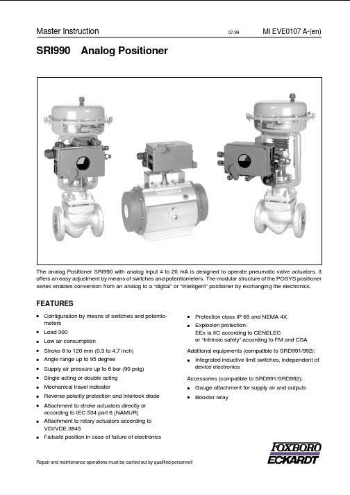
SRI990Analog PositionerThe analog Positioner SRI990with analog input4to20mA is designed to operate pneumatic valve actuators.It offers an easy adjustment by means of switches and potentiometers.The modular structure of the POSYS positioner series enables conversion from an analog to a“digital”or“intelligent”positioner by exchanging the electronics. FEATURES·Configuration by means of switches and potentio-meters·Load300·Low air consumption·Stroke8to120mm(0.3to4.7inch)·Angle range up to95degree·Supply air pressure up to6bar(90psig)·Single acting or double acting ·Mechanical travel indicator·Reverse polarity protection and interlock diode ·Attachment to stroke actuators directly or according to IEC534part6(NAMUR)·Attachment to rotary actuators according to VDI/VDE3845·Failsafe position in case of failure of electronics ·Protection class IP65and NEMA4X ·Explosion protection:EEx ia IIC according to CENELECor“Intrinsic safety”according to FM and CSA Additional equipments(compatible to SRD991/992):·Integrated inductive limit switches,independent of device electronicsAccessories(compatible to SRD991/SRD992):·Gauge attachment for supply air and outputs ·BoosterrelayMaster Instruction07.99MI EVE0107A-(en) Repair and maintenance operations must be carried out by qualified personnel!TABLE OF CONTENTSCHAP:CONTENT PAGE1METHOD OF OPERATION (3)1.1General (3)1.2Block diagram (3)1.3Operation (3)1.4Safety Requirements (4)2LABELS (5)3DESIGN (6)3.1Pneumatic accessories (7)4MOUNTING TO LINEAR ACTUATORS..8 4.1NAMUR Mounting(left hand) (8)4.2NAMUR Mounting(right hand) (10)4.3Direct Mounting (12)5MOUNTING TO ROTARY ACTUATORS.14 6PNEUMATIC CONNECTIONS (16)7ELECTRICAL CONNECTION (17)8START-UP (18)8.1General (18)Setting of-8.2-Direction of rotation of feedback shaft (19)8.3-Input Signal Range (20)Split Range (20)8.4-Gain(G) (21)8.5-Zero(ZERO)and Span(S) (21)8.6-Damping(D) (21)8.7-Travel indicator (21)8.8Air reducing throttles (22)8.9Basic adjustment of electronics (22)8.10Pneumatic test.....................22CHAP:CONTENT PAGE 9DECOMMISSIONING (22)10TROUBLE-SHOOTING GUIDE (23)11MAINTENANCE (24)11.1General (24)11.2Supply filter replacement (24)11.3Removal of the electronics unit (24)11.3.1Conversion of positioner (24)11.4Replacement of mechanical andpneumatic units (25)11.4.1Amplifier replacement (25)11.4.2Preamplifier replacement (25)11.4.3IP-module replacement (25)11.4.4Feedback unit replacement (25)12OPTION“Limit switch” (26)APPENDIX13SYSTEM CONFIGURATION (27)DIMENSIONS (28)2SRI990MI EVE0107A-(en)1METHOD OF OPERATION1.1GeneralThe intelligent positioner SRD9911and the pneumatic ac-tuator2form a control loop with the setpoint value w(from master controller or control system),the output pressure y and the position x of the actuator on valve3.The positioner can be attached to both linear actuators and rotary actuators.Actuators with spring force are controlled by a single acting positioner.Actuators without spring force are controlled by a double acting positioner.The positioner can be operated by means of switches and potentiometers.1.2Block diagram1.3OperationThe supply of the electronics unit is diverted from the cur-rent signal4to20mA at the input.The current value is measured and is suited in input circuit 9to the desired input range(control action or split range) via switches S4-S7.In circuit10the signal is provided with an adjustable time constant settable via potentiometer P5.The resulting internal signal is guided to the analog control circuit11,the gain of which is adjustable via potentiometer P4.The output of the control circuit drives the electro-mechanic converter(IP module)12,which controls the analog single acting or double acting pneumatic amplifier 14through the preampifier13.The output of the amplifier 14is the output pressure y(y1,y2)to the actuator.The pneumatic amplifiers are supplied with supply air Ps 1.4to 6bar(20to90psig).For the supply air,we recommend the FOXBORO ECKARDT FRS923filter regulator.The position x of the actuator is measured by the position sensor(conductive plastic potentiometer)15.The desired direction of rotation is set in17via switches S1and S2. The SPAN is suited to the stroke/rotation angle range via potentiometer P2,while ZERO is set in19via potentio-meter P3.With switch S3potentiometer P1provides an internal zero adjustment in18carried out by the manufac-turer(service function).The resulting feedback signal is guided to control circuit11.The IP module receives its maximum drive current via switch S8enabling checking of the funktion of the pneuma-tic unit.The position x of the actuator is independently displayed at the mechanical travel indicator16.The mechanical limit switch22(optional)enables indepen-dent alarm signals.MI EVE0107A-(en)SRI99031.4Safety requirementsAccident preventionThis device complies with regulations for the prevention of accidents Power-Driven Work Aids(VGB5)of1st October1985.In option“limit switch”do not touch control vane during operation-danger of injuries!Electrical safetyThis instrument satisfies the conditions for safety class III, overvoltage category I according to EN61010-1orIEC1010-1.Any work on electrical parts must be done by qualified per-sonnel if any supply is connected to the instrument.The instrument must be used for its designated purpose and connected in accordance with its connection diagram (see pages17and27).Locally applicable installation regulations for electrical equipment must be observed,e.g.in the Federal Republic of Germany DIN VDE0100resp.DIN VDE0800.The instrument contains no built-in fuses.The instrument must be operated with safety extra low voltage SELV or SELV-E.Safety precautions taken in the instrument may be render-ed ineffectual if the instrument is not operated in accord-ance with the Master Instructions.Limitation of power supplies for fire protection must be ob-served due to EN61010-1,appendix F or IEC1010-1.Explosion protection(Only if ordered)Technical data for explosion protection see Product Specifi-cations Sheet PSS EVE0107A-(en).For installations located in explosive atmospheres,all rele-vant national regulations and installation conditions must be observed,e.g.in the Federal Republic of Germany ElexV and DIN VDE0165.Attention:When repairing explosion-protected equipment,observe the national regulations.Repairs involving parts must be manufacturer’s original parts.The following applies to the Federal Republic of Germany: Repairs involving parts required for explosion protection must either be carried out by the manufacturer or by autho-rized personnel and confirmed by certificate.EMC and CEFor notes regarding Electromagnetic compatibility EMC and CE labels see Product Specifications Sheet PSS EVE0107 A-(en).In order to ensure EMC protection,the electronic board has to be screwed to the housing.4SRI990MI EVE0107A-(en)2LABELSC Additional label for option “Limit switches”DImprinted references regarding to settingsSRI990[Device specification,Model Code ]SER.No [Serial number ]ECEP [Number for special engineered version ]Measurement point label (Example)Directly fixed or attachedoption “Limit switches”(Example)MI EVE0107A-(en)SRI9905Nameplate A (Example)Without Ex-protectionNameplate A (Example)Classified intr.safe by CENELEC Type of protection “EEx ia ”3DESIGN6SRI990MI EVE0107A-(en)1a Adapter1/2"-14NPT(see accessories)1b Cable gland PG13.52Plug,interchangeable by Pos.13Screw terminals11+12for input(w)I–to measure input current(see also item23)4Ground connection5Female thread1/4-18NPT for output I(y1)6Female thread1/4-18NPT for air supply(s)7Female thread1/4-18NPT for output II(y2)8Direct connection hole for output I(y1)9Feedback shaft10Connection manifold for mounting to linear actuators 11Connection base for mounting to rotary actuators 12Travel indicator17Air reducing throttle*for output I18Air reducing throttle*for output II19Shaft for limit switch connection20Cover with window to1221Air vent,dust and water protected22Nameplate23Connections for current measurement,2mm dia.(integrated in side of terminals)26Arrow points to flat of feedback shaft at angle0°27Ball valve for protection class NEMA4X*Service only3.1Pneumatic AccessoriesWhen mounting,check the proper seating of the O-rings and bolt on the accessories with the two M8bolts.Unused outputs are closed by means of plastic plugs.MI EVE0107A-(en)SRI99073x1/4-18 NPT3x1/4-18 NPTL x B x H =100 x 30 x 45 mmL x B x H =83 x 20 x 25 mmL x B x H =121 x 39 x 81 mmL x B x H =110,5 x 39 x 81 mm4MOUNTING TO LINEAR ACTUTAORS4.1NAMUR Mounting -left hand -Applicable to actuators with cast yoke or pillar yoke acc.to NAMUR (DIN IEC 534-6).Mounting the positioner with pneumatic connections on theleft side and electrical connections on the lower right side.Attachment of the positioner to the actuator is made to the left using the mounting bracket and feedback lever for a NAMUR mount.Use:attachment kit EBZG -H for a cast yoke,or attachment kit EBZG -K for a pillar yoke.·The side outputs I (orI and II,see page 6)are used.The rear output I is closed bymeans of a lock screw 522588013.Pneumatic connections:Do not use Teflon tape for seal-ant.The fine fibres could disturb the function of the e only Loctite ®#243for sealant 1).Screw-type glands for electrical connections are positioned on the lower or right side.Any unused threaded holes are closed by plugs.When putting on the housing cover note that the air vent should face-down (see photo above).4.1.1Preparation of the positionerRotate the shaft stub of shaft 9so that the flat on the shaft stub is perpendicular to the arrow 26on the housing (detail see page 13).Fasten the feedback lever A to the shaft by means of spring washer and nut M8.1)Apply only to male thread4.1.2Preparation of the actuatorScrew the and lock it A carrier screw on It consists of a stud S ,which is screwed into the coupling piece K (with 3mm Allen key)and locked with a lock nut M6.The threaded sleeve H is screwed onto it and locked with a lock nut M6.Make sure that the bolt is adjusted to the right length!Fasten the mounting bracket to the left side of the yoke.For a cast yoke use a screw M8x 30,for a pillar yoke use two U-bolts and two nuts.4.1.3Mounting of the positionerFasten the positioner to the mounting bracket using two spring washers and two screws M8x 80.Note,the carrier bolt B is in the slot of the feedback lever A and the compensating spring F touches the carrier bolt.Fig.:Feedback leverFor optimum utilization of the positioner operating range,it is recommended that the arrangement is adjusted accor-ding to the following procedure before fixing.At an actuator position in the middle of travel range,the feedback lever po-sition should be perpendicular to the actuator stem and the angle range should be between 10°...+10°and 30°...+30°.Procedure:Set the actuator to the middle of its travel range by supply-ing it with an independent pressure.Fasten the mounting bracket so that carrier bolt and the mark on mounting bracket are about the same distance from the valve body.Fasten the positioner to the mounting bracket so that a suitable angle range is selected.It is recommended that the pneumatic and electrical con-nections are made after adjusting the position.8SRI990MI EVE0107A-(en)MI EVE0107A-(en)SRI99094.2NAMUR Mounting -right hand -Right-hand mounting is done if for instance left-hand moun-ting is not possible for structural reasons.Applicable to actuators with cast yoke or pillar yoke acc.to NAMUR (DIN IEC 534-6).Mounting the positioner with pneumatic connections on theright side and electrical connections on the left side.Attachment of the positioner to the actuator is made to the right using the mounting bracket and feedback lever for a NAMUR e:attachment kit EBZG -H for a cast yoke,or attachment kit EBZG -K for a pillar yoke.·The side outputs I (or I and II,see page6)are used.The rear output I is closed by means of a lock screw 522588013.Pneumatic connections:Do not use Teflon tape for seal-ant.The fine fibres coulddisturb the function of the e only Loctite ®#243for sealant 1).Screw-type glands for electrical connections are positioned on the left side.Any unused threaded holes are closed by plugs.When putting on the housing cover note that the air vent should face-down (see photo above).4.2.1Preparation of the positionerRotate the shaft stub of shaft 9so that the flat on the shaft stub is perpendicular to the arrow 26on the housing (detail see page 13).Fasten the feedback lever A to the shaft by means of spring washer and nut M8.1)Apply only to male thread4.2.2Preparation of the actuatorScrew the and lock it coupling It consists of a stud S ,which is screwed into the coupling piece K (with 3mm Allen key)and locked with a lock nut M6.The threaded sleeve H is screwed onto it and locked with a lock nut M6.Make sure that the bolt is adjusted to the right length!Fasten the mounting bracket to the left side of the yoke.For a cast yoke use a screw M8x 30,for a pillar yoke use two U-bolts and two nuts.4.1.3Mounting of the positionerFasten the positioner to the mounting bracket using two spring washers and two screws M8x 80.Note,the carrier bolt B is in the slot of the feedback lever A and the compensating spring F touches the carrier bolt.Fig.:Feedback leverFor optimum utilization of the positioner operating range,it is recommended that the arrangement is adjusted accor-ding to the following procedure before fixing.At an actuator position in the middle of travel range,the feedback lever position should be perpendicular to the actuator stem and the angle range should be between 10°...+10°and 30°...+30°.Procedure:Set the actuator to the middle of its travel range by supply-ing it with an independent pressure.Fasten the mounting bracket so that carrier bolt and the mark on mounting bracket are about the same distance from the valve body.Fasten the positioner to the mounting bracket so that a suitable angle range is selected.It is recommended that the pneumatic and electrical con-nections are made after adjusting the position.10SRI990MI EVE0107A-(en)A B4.3Direct MountingActuators with appropriately prepared yoke (PA200,PA350)enable mounting of the SRD991direcly to the actuator yoke.The attachment of the positioner is accomplished by bolting it directly to the actuator yoke using the feedback lever for a direct mount (with attachment kit EBZG -D).The rear output I and the side outputs I and II are used as follows (see page 6):·Actuator single acting,spring force closes:The rear output I is used (remove lock screw in hole D ).The side output I is closed by means of a lock screw 522588013.·Actuator single acting,spring force opens:The side output I is used.The rear output I is closed by means of a lock screw.·Actuator double acting:The rear output I and the side output II is used.The side output I is closed by means of a lock screw.Pneumatic connections:Do not use Teflon tape for sealant.The fine fibres could disturb the function of the e only Loctite ®#243for sealant 1).Screw-type glands for electrical connections are positioned on the side.Any idle female threads are closed by means of plugs.When putting on the housing cover note that the air vent should face-down (see photo above).1)Apply only to male thread.4.3.1Preparation of the positionerRotate the shaft stub of shaft 9so that the flat on the shaft stub is perpendicular to the arrow 26on the housing (detail see page 13).Fasten the feedback lever A to the shaft by means of spring washer and nut M8.4.3.2Preparation of the actuatorScrew in the carrier bolt B on the coupling piece K on the drive spindle S at the lower left and lock it by means of a nut M6.R4.3.3Mounting of the positionerFasten the positioner to the upper part of the yoke using 2spring washers and 2screws M8x 80,as shown above.The rear output I of positioner has contact to the air duct R in the yoke.Attention:Note the correct position of the O-ring on the yoke for the rear connection I!Note,the carrier bolt B is in the slot of the feedback lever A and the compensating spring F touches the carrier bolt.Fig.:Feedback leverA BFM6BKS4.3.4Mounting dimensions–direct mounting–5MOUNTING TO ROTARY ACTUATORS5.1Type of mountApplicable to rotary actuators that meet the VDI/VDE3845 standard for mounting.Installation position of positioner: Mount the positioner so that the pneumatic connections are in the same direction as the longitudinal drive axis of the actuator as shown in the photograph below.Attention:The feedback shaft9of the SRD has no me-chanical stop,therefore may spin round.The permissible rotation angle range is between+50and–50degrees around the arrow at the housing concerning the flat area of the feedback shaft(also see detail page13bottom).Since a rotary actuator has a rotary angle of about90degrees the mounting as described in the following must be carried out very precise.Attachment of the positioner to the actuator is made by using the rotary adaptor kit EBZG-R.·Either the side outputs I(or I and II)are used and the rear output I is closed by means of the lock screw522588013.Pneumatic connections:Do not use Teflon tape for seal-ant.The fine fibres could disturb the function of the SRD. Use only Loctite®#243for sealant1).Screw-type glands for electrical connections are used as needed.Any unused threaded holes are closed by plugs. Caution!Prevent accumulation of water in the instrument in this mounting position by sealing cable entry against water.Provide a continuous supply of dry instrument air.1)Apply only to male thread.2)Failsafe position:Defined position in case of failure of input signal 5.1.1Preparation of positionerValve must be in failsafe position2)and the direction of rota-tion of the actuator drive shaft must be known.These items are extremely important for proper functioning.These items can be checked as follows in case they are not clear: In the single-acting actuator the force of the installedsprings closes.The pressure-less actuator is in failsafe position.Through manually feeding compressed air itcan be seen whether the actuator drive shaft rotates to the left or to the right.In the powerless SRD is y1pressureless.In the double-acting actuator without spring reset both air chambers are basically equal.Failsafe position can be either“open”or“close”.Therefore,indication of the fail-safe position has to be determined by engineering.Then the direction of rotation may be determined bymanual feeding of compressed air.In the powerlessSRD is y1pressureless and y2under pressure.Bolt2is screwed into actuator drive shaft1for subsequent centering of the rotary adaptor3.The attachment console is mounted to the stroke actuator(see photo). Attachment diagram for bracket5.1.2Preparation of the actuatorFirst the rotary adaptor is being prepared:For attachment to a counter-clockwise or left turning ac-tuator secure the stud screw 4in the threaded hole “L ”of the rotary adaptor;hole “R ”remains open.See Fig.27.For attachment to a clockwise or right turning actuator secure the stud screw 4in the threaded hole “R ”of the rotary adaptor;hole “L ”remains open.See Fig.28.Now place the rotary adaptor 3with two washers 5on the feedback shaft 9of the positioner against the stop.Note :When the product temperature rises,the drive shaft 1be-comes longer.Therefore,the rotary adaptor 3must be mounted so that approx.1mm (0.04in.)of clearance re-sults between the drive shaft 1and the rotary adaptor 3.This is achieved by placing an appropriate number of washers 5on the feedback shaft stub 9before attaching the rotary adaptor.Two washers should result in a clearan-ce of 1mm.SRIFigure 27:Mounting if actuator is rotating to the leftNow screw and tighten the bolt in the coupling against the flat part of the feedback shaft(do not screw against thread!).Finally turn the feedback shaft in such a way that the arrow of the coupling points to the arrow of the SRI housing.Beginning and end positions of the actuator drive shaft 1and feedback shaft 9are marked in figure 27(left-rotating actuator)and in figure 28(right-rotating actuator)by arrows for the respective direction of rotation.The feedback shaft is now in the normal positioncorresponding to the failsafe position of the actuator.No shifting of feedback shaft anymore!5.1.3Mounting of positionerSRI and actuator are in failsafe position.Attach the SRI on the console in such a way that the catch of coupling 3is guided into the groove of shaft e bolt 2to center and align the positioner to the actuator.Be careful not to shift shafts 1and 9and that both shafts are exactly flush.Fasten the positioner to the bracket by means of 4lock wa-shers and 4screws M6x 12SRIFigure 28:Mounting if actuator is rotating to the rightFollowing alignment and mounting of the positioner to the valve,pneumatic tubing has to be provided.The connection illustrations depend on the respective ver-sion.Explanation of abbreviatons:sSupply airy1-d Output 1for direct mounting,depressurized atcurrentless electronics.When using this output y1has to be closed by means of hex.screw.y1Output 1,depressurized at currentless electronics.When using this output,y1-d has to be closed by means of sealing screw and O-ring.y2Output 2for double-acting actuator.Full pressure at currentless electronics.Closed at single-acting actuator.n1Hex.screw with NPT thread n2Sealing screw with O-ringsy1sy1s y2The safety requirements on page4must be observed! Unused cable glands should be closed off.Guide cable through gland1.The gland is suitable for cable diameters of6to12mm(0.24to0.47in).Observe the tightness of the cable entry.Provide electrical connection of input line at screw terminals 3marked11+and12.The terminals are suitable for wire cross-sections of0.3to2.5mm2(22-14AWG).Note:When connecting shielded cable connect the cable shield only to the system!Do not connect the cable shield to the SRI!40)Connection to terminals(pos.3+,3–):11+Input w+12–Input w–The input current can be measured at tip jacks23+and23-(integrated in terminals,underneath the screws).The tipjacks fit plugs with a diameter of2mm(0.08in)In order to improve EMV protection by integration into localgrounding the internal and external grounding conductconnection4is available.GW Binary output ext.supplied8START-UP 8.1GeneralFirst of all,the nameplate should be checked,especially with respect to references to Ex/non-Ex,input signal, single/double acting.Before starting the positioner the SRI has to be mounted to the actuator;an input signal4to20mA or split range have to be available.The supply air connection must have suf-ficient capacity and pressure of1.4to6bar(20to90psig) and should not exceed the maximum operating pressure of the actuator.The SRI990can be adjusted by means of switches and potentiometers when the housing cover is opened.At initial start-up various adjustments have to be set.The following procedure is recommended:·Setting of direction of rotation of feedback lever(chap-ter8.2)·Setting of input signal rangee.g.4to20mA or split range(chapter8.3)·Setting of gain(chapter8.4)·Setting of zero and span(chapter8.5)·Setting of damping(time constant,chapter8.6)·The position indicator12is attached to the desired posi-tion after selection of the transmission at indicator shaft (chapter8.7)·The air capacity throttles at the pneumatic output (screws17and18underneath of the SERVICE ope-nings)are factory-set to the operating value and are nor-mally not reset(exception see chapter8.8).·When attaching the housing cover make sure that the venting opening points to the bottom.1)Adjustment of electronic board(in workshop,see page23)Settings via switches and potentiometersFor the setting of the SRI990and the adjustment of various parameters8dip switches and5potentiometers are avail-able.See electronics imprint as follows:·Zero point(ZERO):P3·Span(S):P2·Gain(G):P4·Damping(D):P5·Electronics alignment:P11)Single-threaded potentiometers with limited rotation angle to set gain(G)and damping(D)are available,where the actual position is indicated by an arrow.To set zero point(ZERO),span(S)and the electronics alignment1)multiple-threaded potentiometers(approx.30rotations)without ro-tation limitation are used.The switches are for the setting of:·Direction of rotation of feedback lever(switches1,2)·Electronics adjustment(switch3)1)·Signal range(switches4,5,6and7)·Pneumatic test(switch8)The switchnumbers(1through8)are imprinted on the electronics.The possible switch position(“I”and“II”)are imprinted below switch8.The switch positions are defined as follows:“I”:“II”:8.2Setting of direction of rotationof feedback shaftIf the actuator moves from starting to end position,the di-rection of rotation of the feedback shaft is to the right or lefthand,depending on the mounting method of the positioner selected and on the configuration of the actuator(spring closes/opens/double-acting).For proper functioning this direction of rotation must be set at positioner(via switches1+2).The direction of rotation is defined as direction of rotation of the feedback shaft from the starting to the end position look-ing at the positioner from the front.See following illustration (shown is:left hand mounting,spring closes,direction ofDirection of rotation of feedback shaft of a single-actingDirection of rotation of feedback shaft of the double-actingactuator is a.o.determined by the mounting side and thetubing of the pneumatic outputs to the actuator.It has to beconsidered that in a powerless SRI990the output y1willbecome pressureless and y2contains air supply pressure.The direction of rotation of the feedback shaft is set viaswitches1+2;see the following illustration.L:left-hand rotating feedback shaft switch1+2on“I”R:right-hand rotating feedback shaftt:switch1+2on“II”Remarks:If the direction of rotation is not in the right man-ner,the actuator moves to the end position with full force,and the positioner cannot be controlled.DefinitionsStroke,stroke range of the membrane actuator is defined for rotary actuator as angle,angle rang e..0%position is the mechanical impact at actually closed valve(caution if using handwheel and mechanically adjustable stroke limitation!)100%position is the mechanical impact at actually open valve.8.3Setting of Input Signal RangeThe following input signal ranges can be set for the SRI990The switch positions for the setting of various signal ranges are imprinted on the electronics.See illustration.For 4to 20mA the switches 4to 7are set to position “I ”(as shown).This concludes the setting of the input signal range!Split RangeIf several positioners are operated at one current loop in se-quence with the standard signal 4to 20mA,individual valve positions may be allocated to each device,which also may overlap if necessary.This function is useful if an additional control range is de-manded which cannot be covered by one valve only.A valve of smaller nominal size can be applied overtaking the smallest quantities;a parallel mounted valve of bigger no-minal size takes on the larger quantities.Example:Setting the signal range to 12to 20mAIt is recommended to shut off current of the positioner prior to resetting of the input signal range (turn-off input signal).The switches 4and 5are set to position “I ”and switches 6and 7to position “II ”.The individual switch positions are shown in the following illustration.Split range,subdivision of input signal rangeExample:At low current,only the smaller valve positions;from approx.50%the large valve is added420mAm A12mA。
YAMAHA-SPX990效果器中文使用操作说明
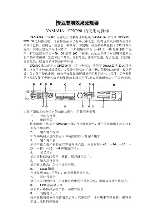
专业音响效果处理器YAMAHA SPX990 的使用与操作YAMAHA SPX990专业综合效果处理器是继YAMAHA 公司在SPX900、SPX100之后推出的,尽管推出至今已有四五年光景,同时也在众多的专业音响系统(包括一些剧场、夜总会、歌舞厅)中使用,该效果器共提供了280种效果程序,其中预置程序为1-80个,用户使用程序为1-99个,00是第100个程序,扩展记忆程序为-99,00是第100个程序,此处还包括了对混响和前期反射声的真实模拟,延迟和回声效果,调制效果,处理声效果,复合效果,门混响,音调效果,以及可循环的采样程序等。
SPX990在功能上比SPX900又上了一个档次,采用了20bitA/D和D/A转换器,增加了多种前后级效果,以及带有记忆的扩展卡槽,简捷的功能键,数据轮等,虽简化了操作步骤,但由于液晶显示屏所显示的数据有林林种种,又全都是英文缩写,使不少操作者感到使用起来极为不便,难以正确调整其中的各种参数,为此下面就具体介绍它的功能与操作,供使用者参考:一、控制与连接1、电源开关按此键可打开/关闭SPX990电源,当电源打开后,显示屏将调出上次关机时的程序和参数。
2、输入电平控制内/外部旋钮分别控制左/右声道的模拟信号输入电平。
3、输入电平表立体声输入电平表将左右声道分成八段,分别对应-42,-36,-30,-24,-18,-12,-6和削波灯指示。
4、记忆指示显示选择记忆的类型:预置,用户或记忆卡。
5、输入选择指示显示输入状态:立体声或单声道。
6、MIDI指示当接收到MIDI信号时,此显示器将被点亮。
7、程序号显示显示当前的程序号,在选择过程中程序号将闪亮,调出或存储后将常亮。
8、LCD液晶显示器液晶显示器将显示程序名,参数等信息。
9、功能键(上/下)用来直接调出或按照普通方法调出效果程序,还可用来存储操作,编辑液晶屏上选择的参数值。
10、数据调节轮用来调节程序号或参数值。
990说明书

* 设定后测定的数据将会被存入内部记忆库。
* 进行数据演算(参考⑹数据演算)时,请在测量之前先设定数据记忆。如果在测量完毕之后
再设定数据记忆的话,测得的数据将无法进行数据演算(统计)。
⑶按
键 将光标移动到 删除 ,按
键,则最新测量的数据将被删除。
⑷ 如果不需要对数据存储, 按
键选择 数据存储解除 ,
3.各部位名称
〈主机〉
背面
吊链孔
显示屏
蜂鸣器
电池盖
探头支架 探头支架
探头 V型块
3/16
〈标准配置〉
基体
(铁基体\铝基体)
标准片
〈可选附件〉
5# 电池
便携袋
说明书
标准片
专用台架 打印机 LW-990 VZ-330
打印机连线 连线
电脑软件
VZC-53
RS232C-USB LDL-02
4.显示屏说明
电量提示
键后则无任何变更
⑸ 数据演算
此功能可以进行最大值、最小值、标准偏差、平均值的表示以及计算范围的设定。
进行数据演算时,请在测定前将基体设置为数据存储(参照⑷数据存储)
⑴ 按照设定方法中⑴⑵的操作顺序进行。
⑵ 利用
键将光标滚动至数据范围内的数值上再按
数据演算
键, 按
键填入测量次数N值。
数据演算号码
按 键后,显示演算数据的总数,再按 键后显示
键移动至返回 。 按
键数据则不会被删除
又返回至测量画面。
⑶ 数据存储
设定是否将测定的数据放入记忆库。
⑴ 按照设定方法中⑴⑵的操作顺序进行。
数据存储
⑵ 将测定数据放入记忆库时,按
键
Amatrol 移动电动机故障诊断学习系统(990-MC1F)说明书

Portable WorkstaƟon
Amatrol’s Portable Motor Control Troubleshoo ng Learning System (990-MC1F) features standard industry components like a 3-phase AC squirrel cage motor and uses 3-phase AC for power and 24 VDC for control all packed within a space-saving, portable product. These real-world components will prepare learners for work opportuni es in industries where motor control is used in applica ons like conveyor control and driving large u lity pumps. The 990-MC1F also uses FaultPro, Amatrol’s unique electronic fault inser on, to teach motor control troubleshoo ng skills, such as control relay, reversing contactor, limit switch, and pushbu on troubleshoo ng.
Mobile, Durable - Use Anywhere!
The 990-MC1 is set within a durable ABS plas c case featuring wheels and a handle so that moving this world-class trainer from one des na on to another is safe and easy. Another advantage of the 990-MC1 is the minimal set-up me. Once the case’s cover is removed, the trainer sits upright on the training surface.
爱华XR-H220MD音响维修手册

BASIC TAPE MECHANISM : TN-591SW-143MD / CD STEREO SYSTEMXR-H220MD XR-H235MD XR-H236MD XR-H238MD S/M Code No. 09-997-413-6N1D D D DSERVICE MANUALD A T ABASIC CD MECHANISM : 4ZG-1 Z3RNSMDJM BASIC MD MECHANISM : ZZG-7 DMMODEL CODE : 8ZNB9-9133(CX-SNH220MD SM)8ZNB9-9293(CX-SNH235MD STM)8ZNB9-9233(CX-SNH236MD SM)8ZNB9-9333(CX-SNH238MD SM)8ZNSK-9237(SX-SNH220 SAN)8ZNSL-9597(SX-SNS115 STAN)8ZNSL-9437(SX-SNS115 SAN)8ZNSK-9437(SX-SNH220 S2N)SYSTEMXR-H220MD CASSIVER CX-SNH220MD SPEAKER SX-SNH220 SAN XR-H235MD CX-SNH235MD XR-H236MD CX-SNH236MD SX-SNS115 SAN XR-H238MDCX-SNH238MDSX-SNH220 S2NSX-SNS115 STANTABLE OF CONTENTS SPECIFICATIONS (3) (4)5 DISASSEMBLY INSTRUCTIONS........................................................................................................6-8 ELECTRICAL MAIN PARTS LIST.....................................................................................................9-13 TRANSISTOR ILLUSTRATION (14)BLOCK DIAGRAM-1 (MAIN)...........................................................................................................15, 16 BLOCK DIAGRAM-2 (MD)..............................................................................................................17, 18 WIRING-1 (MAIN)...........................................................................................................................19, 20 SCHEMATIC DIAGRAM-1 (MAIN)..................................................................................................21, 22 WIRING-2 (FRONT)........................................................................................................................23, 24 SCHEMATIC DIAGRAM-2 (FRONT)..............................................................................................25, 26 WIRING-3 (MD)...............................................................................................................................27, 28 SCHEMATIC DIAGRAM-3 (MD).....................................................................................................29, 30 WIRING-4 (INTERFACE)................................................................................................................31, 32 SCHEMATIC DIAGRAM-4 (INTERFACE)......................................................................................33, 34 WIRING-5 (MECHANISM)..............................................................................................................35, 36 WIRING-6 (PT).. (37)TEST MODE....................................................................................................................................38-41 ELECTRICAL ADJUSTMENT/PRACTICAL SERVICE FIGURE.....................................................42-47 IC DESCRIPTION............................................................................................................................48-55 IC BLOCK DIAGRAM.......................................................................................................................56-59 FL GRID ASSIGNMENT/ANODE CONNECTION..........................................................................60, 61 MECHANICAL PARTS LIST 1/1.. (62)MECHANICAL EXPLODED VIEW 1/1............................................................................................63, 64 TAPE MECHANISM EXPLODED VIEW 1/1...................................................................................65, 66 TAPE MECHANISM PARTS LIST 1/1.. (67)MD MECHANISM EXPLODED VIEW 1/4 (68)MD MECHANISM PARTS LIST 1/4 (69)MD MECHANISM EXPLODED VIEW 2/4 (70)MD MECHANISM PARTS LIST 2/4 (70)MD MECHANISM EXPLODED VIEW 3/4 (71)MD MECHANISM PARTS LIST 3/4 (72)MD MECHANISM EXPLODED VIEW 4/4 (73)MD MECHANISM PARTS LIST 4/4 (74)SPEAKER DISASSEMBLY INSTRUCTIONS (75)SPEAKER PARTS LIST 1/1 (76)ACCESSORIES/PACKAGE LIST (77)2SPECIFICATIONS•••34!!56DISASSEMBLY INSTRUCTIONSAAB CCAB78DESCRIPTIONNO.NO.IC87-017-888-080 1A IC,NJM4558MD87-A20-870-010 1A IC,GP1F37R87-A20-971-040 1A C-IC,SN74LV14APW87-A20-707-010 2B C-IC,CXA2523AR87-A20-708-010 2D C-IC,CXD2652AR87-A20-709-040 1H C-IC,BD7910FV87-ZG9-607-010 2M C-IC,CXP81952M-523R87-ZG9-606-040 2M C-IC,MN41V4400SJ-0887-A20-755-080 1B C-IC,AK93C45AF87-A20-710-040 1B C-IC,S-8110AMP87-A20-711-040 1E C-IC,BA5970FP87-A20-712-040 1B C-IC,BA6417F87-A21-110-040 2A C-IC,AK4519VF87-017-853-040 1B IC,NJM2100V87-A20-797-040 1B C-IC,NJU7221U3087-A20-798-040 1B C-IC,NJU7221U3587-A20-714-040 1B C-IC,NJM2370U3387-017-889-010 1A IC,NJM4558LD87-A20-715-010 1C IC,M62439SP87-070-127-110 1C IC,LC72131 D87-A20-716-010 1E IC,TA2040AP87-A20-913-010 1D IC,LA1837NL87-A21-103-040 1E C-IC,MM1454XFBE87-A20-914-010 1B IC,SPS-442-1-F8Z-NB9-601-010 1M C-IC,LC876564V TRANSISTOR89-213-750-010 1A TR,2SB1375 (25W)87-A30-076-080 0E C-TR,2SC3052F87-A30-071-080 0E C-TR,RT1N 144C87-A30-075-080 0E C-TR,2SA1235F87-026-225-080 1A FET,2SJ106GR87-A30-072-080 0E C-TR,RT1P 144C87-A30-074-080 0E C-TR,RT1P 141C87-A30-087-080 0E C-FET,2SK215887-026-423-080 0E C-TR RN230589-115-884-080 0E CHIP -TRANSISTER 2SA1588Y 89-341-164-080 0E CHIP-TRANSISTOR,2SC4116 Y 87-026-412-080 0E C-TR RN130589-213-702-010 1A TR,2SB1370 (1.8W)87-026-610-080 0E TR,KTC3198GR87-A30-196-080 0E TR,2SC4115SRS87-026-609-080 0E TR,KTA1266GR87-026-269-080 0E TR,DTA114ES87-026-219-080 0E TR,DTA144ES (0.3W)87-A30-256-010 1A TR,2SD193387-A30-255-010 1A TR,2SB134287-A30-047-080 0E TR,CSD655E87-A30-091-080 1E FET,2SJ46087-A30-090-080 0E FET,2SK254187-026-218-080 0E TR,DTC144ES (0.2W)87-026-214-080 0E TR,DTA114YS (0.3W)89-305-352-380 0E TR,2SC535(B/C)87-026-210-080 0E CHIP-TR,DTC144EK87-A30-198-080 0E TR,KTC3199GRDIODE87-A40-304-080 0E ZENER,DZ6.2M87-A40-313-080 0E C-DIODE,MC 284087-A40-469-080 0E C-DIODE,HSM2838CTR87-A40-468-080 0E C-DIODE,HSM2836CTR87-A40-299-080 0E ZENER,DZ5.1M87-001-166-080 0E DIODE,1SS30187-A40-412-040 0E C-DIODE,SB05-05CP87-A40-393-090 0E DIODE,1N5402GW(F20)87-A40-336-080 0E ZENER,MTZJ27D T-7287-020-465-080 0E DIODE,1SS133 (110MA)87-A40-345-080 0E ZENER,MTZJ10C87-070-274-080 0E DIODE,1N4003 SEM87-A40-466-080 0E ZENER,MTZJ2.7A87-017-931-080 0E ZENER,MTZJ5.6B87-A40-509-080 0E ZENER,MTZJ6.8C87-A40-270-080 0E C-DIODE,MC283887-A40-269-080 0E C-DIODE,MC2836MAIN C.BC101 87-016-495-090 1B CAP,E 3300-25 SMGC104 87-A10-011-090 2A CAP,E 2200-25 SMGC105 87-018-127-080 0E CAP, CER 470P-50VC106 87-010-260-080 0E CAP, ELECT 47-25VC107 87-010-384-080 0E CAP, ELECT 100-25VC108 87-010-381-080 0E CAP, ELECT 330-16VC111 87-010-247-080 0E CAP, ELECT 100-50VC112 87-010-263-080 0E CAP, ELECT 100-10VC113 87-010-403-080 0E CAP, ELECT 3.3-50VC114 87-010-374-080 0E CAP, ELECT 47-10VC115 87-A11-007-080 0E CAP,M 0.047-50 J DEC116 87-A11-007-080 0E CAP,M 0.047-50 J DEC122 87-010-384-080 0E CAP, ELECT 100-25VC123 87-010-384-080 0E CAP, ELECT 100-25VC124 87-A11-132-080 0E CAP,TC U 0.01-50 K BC130 87-018-131-080 0E CAP, CER 1000P-50VC152 87-010-409-080 1A CAP,E 220-50 SMEC207 87-010-544-080 0E CAP, ELECT 0.1-50VC208 87-010-544-080 0E CAP, ELECT 0.1-50VC209 87-018-133-080 0E CAPACITOR,CER 4700P-16V C210 87-018-133-080 0E CAPACITOR,CER 4700P-16V C211 87-010-403-080 0E CAP, ELECT 3.3-50VC212 87-010-403-080 0E CAP, ELECT 3.3-50VC213 87-010-260-080 0E CAP, ELECT 47-25VC214 87-010-260-080 0E CAP, ELECT 47-25VC217 87-A11-008-080 0E CAP,M 0.056-50 J DEC218 87-A11-008-080 0E CAP,M 0.056-50 J DEC219 87-010-544-080 0E CAP, ELECT 0.1-50VC220 87-010-544-080 0E CAP, ELECT 0.1-50VC229 87-018-123-080 0E CAP, CER 220P-50VC230 87-018-123-080 0E CAP, CER 220P-50VC235 87-018-209-080 0E CAP, CER 0.1-50VC236 87-018-209-080 0E CAP, CER 0.1-50VC237 87-018-134-080 0E CAPACITOR,TC-U 0.01-16 C301 87-018-131-080 0E CAP, CER 1000P-50VC302 87-018-131-080 0E CAP, CER 1000P-50VC303 87-018-195-080 0E CAP, CER 1200P-16VC304 87-018-195-080 0E CAP, CER 1200P-16VC307 87-010-263-080 0E CAP, ELECT 100-10VC308 87-010-263-080 0E CAP, ELECT 100-10VC311 87-A10-773-080 0E CAP,M 0.10-50 JC312 87-A10-773-080 0E CAP,M 0.10-50 JC315 87-010-374-080 0E CAP, ELECT 47-10VC317 87-010-546-080 0E CAP, ELECT 0.33-50VC318 87-010-546-080 0E CAP, ELECT 0.33-50VC323 87-018-209-080 0E CAP, CER 0.1-50VC325 87-018-209-080 0E CAP, CER 0.1-50VC326 87-018-209-080 0E CAP, CER 0.1-50VC360 87-010-401-080 0E CAP, ELECT 1-50VC361 87-010-374-080 0E CAP, ELECT 47-10VC399 87-018-127-080 0E CAP, CER 470P-50VC401 87-010-401-080 0E CAP, ELECT 1-50VC402 87-010-401-080 0E CAP, ELECT 1-50VC403 87-018-118-080 0E CAP,TC-U 82P-50 BC404 87-018-118-080 0E CAP,TC-U 82P-50 BC411 87-010-405-080 0E CAP, ELECT 10-50VC412 87-010-405-080 0E CAP, ELECT 10-50VC452 87-010-382-080 0E CAP, ELECT 22-25VC458 87-018-131-080 0E CAP, CER 1000P-50VC459 87-018-128-080 0E CAP, CERA-SOL SS 560P910REF. NO PART NO.KANRI DESCRIPTION NO.REF. NO PART NO.KANRI DESCRIPTION NO.C461 87-018-126-080 0E CAP,TC-U 390P-50 B C462 87-018-126-080 0E CAP,TC-U 390P-50 B C601 87-018-195-080 0E CAP, CER 1200P-16V C602 87-018-195-080 0E CAP, CER 1200P-16V C611 87-010-545-080 0E CAP, ELECT 0.22-50V C612 87-010-545-080 0E CAP, ELECT 0.22-50V C613 87-010-545-080 0E CAP, ELECT 0.22-50V C614 87-010-545-080 0E CAP, ELECT 0.22-50V C615 87-018-104-080 0E CAP,TC-U 10P-50 SL C616 87-010-260-080 0E CAP, ELECT 47-25V C617 87-010-260-080 0E CAP, ELECT 47-25V C701 87-010-404-080 0E CAP, ELECT 4.7-50V C702 87-018-134-080 0E CAPACITOR,TC-U 0.01-16 C703 87-018-134-080 0E CAPACITOR,TC-U 0.01-16 C704 87-018-131-080 0E CAP, CER 1000P-50V C705 87-018-131-080 0E CAP, CER 1000P-50V C706 87-018-131-080 0E CAP, CER 1000P-50V C707 87-010-112-080 0E CAP, ELECT 100-16V C708 87-A11-144-080 0E CAP,TC U 0.1-50 K B C709 87-010-248-080 0E CAP, ELECT 220-10V C710 87-010-112-080 0E CAP, ELECT 100-16V C712 87-018-149-080 0E CAP,TC-U 15P-50 CH C713 87-018-149-080 0E CAP,TC-U 15P-50 CH C714 87-010-112-080 0E CAP, ELECT 100-16V C715 87-018-119-080 0E CAP, CER 100P-50V C731 87-010-545-080 0E CAP, ELECT 0.22-50V C732 87-010-404-080 0E CAP, ELECT 4.7-50V C733 87-010-545-080 0E CAP, ELECT 0.22-50V C734 87-010-545-080 0E CAP, ELECT 0.22-50V C735 87-018-132-080 0E CAP, CER 2200P-16V C736 87-018-132-080 0E CAP, CER 2200P-16V C737 87-018-134-080 0E CAPACITOR,TC-U 0.01-16 C738 87-010-260-080 0E CAP, ELECT 47-25V C740 87-018-127-080 0E CAP, CER 470P-50V C741 87-010-404-080 0E CAP, ELECT 4.7-50V C742 87-010-400-080 0E CAP, ELECT 0.47-50V C743 87-010-101-080 0E CAP, ELECT 220-16C746 87-018-134-080 0E CAPACITOR,TC-U 0.01-16 C747 87-A11-144-080 0E CAP,TC U 0.1-50 K B C751 87-018-134-080 0E CAPACITOR,TC-U 0.01-16 C752 87-018-143-080 0E CAP,TC-U 4.7P-50 CH C753 87-010-408-080 0E CAP, ELECT 47-50V C755 87-A11-144-080 0E CAP,TC U 0.1-50 K B C757 87-018-134-080 0E CAPACITOR,TC-U 0.01-16 C758 87-010-112-080 0E CAP, ELECT 100-16V C759 87-018-134-080 0E CAPACITOR,TC-U 0.01-16 C761 87-010-404-080 0E CAP, ELECT 4.7-50V C762 87-010-400-080 0E CAP, ELECT 0.47-50V C763 87-010-401-080 0E CAP, ELECT 1-50V C764 87-010-401-080 0E CAP, ELECT 1-50V C765 87-018-115-080 0E CAP, CER 47P-50V C766 87-010-407-080 0E CAP, ELECT 33-50V C768 87-018-208-080 0E CAP 0.047-50FC769 87-010-403-080 0E CAP, ELECT 3.3-50V C770 87-018-134-080 0E CAPACITOR,TC-U 0.01-16 C771 87-010-406-080 0E CAP, ELECT 22-50 C773 87-018-130-080 0E CAP, CER 820P-50V C774 87-010-405-080 0E CAP, ELECT 10-50VC776 87-018-134-080 0E CAPACITOR,TC-U 0.01-16 C781 87-018-195-080 0E CAP, CER 1200P-16V C782 87-018-195-080 0E CAP, CER 1200P-16V C783 87-018-199-080 0E CAP, CER 3300P C784 87-018-199-080 0E CAP, CER 3300P C785 87-010-405-080 0E CAP, ELECT 10-50V C786 87-010-405-080 0E CAP, ELECT 10-50V C787 87-018-195-080 0E CAP, CER 1200P-16V C788 87-018-195-080 0E CAP, CER 1200P-16V C789 87-010-403-080 0E CAP, ELECT 3.3-50V C790 87-010-403-080 0E CAP, ELECT 3.3-50V C804 87-018-134-080 0E CAPACITOR,TC-U 0.01-16C805 87-010-401-040 0E CAP,E 1-50 SMEC807 87-A11-144-080 0E CAP,TC U 0.1-50 K B C808 87-018-134-080 0E CAPACITOR,TC-U 0.01-16 C809 87-018-134-080 0E CAPACITOR,TC-U 0.01-16 C810 87-018-134-080 0E CAPACITOR,TC-U 0.01-16 C811 87-018-134-080 0E CAPACITOR,TC-U 0.01-16 C812 87-010-408-080 0E CAP, ELECT 47-50V C813 87-018-131-080 0E CAP, CER 1000P-50V C901 87-018-209-080 0E CAP, CER 0.1-50V C943 87-A11-144-080 0E CAP,TC U 0.1-50 K B C944 87-018-104-080 0E CAP,TC-U 10P-50 SL CF801 87-008-261-010 1A FILTER, SFE10.7MA5-A CF802 87-008-261-010 1A FILTER, SFE10.7MA5-A CN301 87-A60-620-010 0E CONN,3P V 2MM JMT CN351 87-A60-625-010 0E CONN,8P V 2MM JMTCN601 87-099-719-010 1B CONN,30P TYK-B(X) CN603 87-099-014-010 0E CONN,12P 6216 V CN605 84-ZG1-647-010 0E CONN ASSY,2P FFE801 A8-6ZA-192-030 2Y 6ZA-1 FEJNMJ201 87-A60-602-010 1A JACK,DIA6.3 BLK ST W/SW TC J202 87-A60-238-010 1A TERMINAL,SP 4P (MSC) J206 87-A60-641-010 1A JACK,PIN 4P R/W/B JALCO J601 87-A60-881-010 0E JACK,PIN 2P MSP 242V05 PBSN J801 87-A60-202-010 1A TERMINAL,ANT 4P MSP-154V-02 L201 87-003-383-010 1A COIL,1UH-SL202 87-003-383-010 1A COIL,1UH-SL451 87-007-342-010 0E COIL,OSC 85K BIAS L701 87-005-847-080 0E COIL,2.2UH(CECS) L771 87-A50-266-010 1A COIL,FM DET-2N(TOK) L772 87-A90-053-010 1C FLTR,PCFMT-060(TOK) L801 87-005-847-080 0E COIL,2.2UH(CECS) L981 8Z-NFA-664-010 2M COIL,AMPACK 4L(TOK) R249 87-A00-258-080 0E RES,M/F 0.22-1W J R250 87-A00-258-080 0E RES,M/F 0.22-1W J RY101 87-A90-464-010 1C RELAY, DG12D2-O(M) T1 87-A60-317-010 0E TERMINAL, 1P MSC T2 87-A60-317-010 0E TERMINAL, 1P MSC W101 83-NE2-618-110 1B F-CABEL,5P-2.5 WH102 87-A90-459-010 0E HLDR,WIRE 2.5-5PX701 87-A70-061-010 1A VIB,XTAL 4.500MHZ CSA-309 X731 87-030-394-010 1B VIB,CER CSA3.6MGF228FRONT C.BC9 87-010-322-080 0E C-CAP,S 100P-50 CH C10 87-012-156-080 0E C-CAP,S 220P-50 CH C11 87-012-140-080 0E C-CAP,S 470P-50 CH C14 87-012-140-080 0E C-CAP,S 470P-50 CH C101 87-010-194-080 0E CAP, CHIP 0.047 C124 87-010-196-080 0E CHIP CAPACITOR,0.1-25 C251 87-010-075-040 0E CAP,E 10-16 5L C252 87-012-157-080 0E C-CAP,S 330P-50 CH C253 87-010-196-080 0E CHIP CAPACITOR,0.1-25 C701 87-010-384-040 0E CAP,E 100-25 SME C801 87-010-112-040 0E CAP,E 100-16 C802 87-010-260-040 0E CAP,E 47-25 SME C803 87-010-197-080 0E CAP, CHIP 0.01 DM C804 87-010-197-080 0E CAP, CHIP 0.01 DM C805 87-A11-144-080 0E CAP,TC U 0.1-50 K B C806 87-010-401-040 0E CAP,E 1-50 SME C807 87-010-402-040 0E CAP,E 2.2-50 SME C808 87-010-402-040 0E CAP,E 2.2-50 SME C809 87-010-405-040 0E CAP,E 10-50C810 87-010-805-080 0E C-CAP,S 1-16 Z F C851 87-010-322-080 0E C-CAP,S 100P-50 CH C852 87-010-322-080 0E C-CAP,S 100P-50 CH C853 87-010-322-080 0E C-CAP,S 100P-50 CH C901 87-010-555-040 0E CAP,E 100-10 GASC902 87-010-196-080 0E CHIP CAPACITOR,0.1-2511REF. NO PART NO.KANRI DESCRIPTIONNO.REF. NO PART NO.KANRI DESCRIPTION NO.C903 87-010-494-040 0E CAP,E 1-50 GASC904 87-010-196-080 0E CHIP CAPACITOR,0.1-25 C905 87-012-155-080 0E C-CAP 180P-50CH C906 87-010-312-080 0E C-CAP,S 15P-50 CH C907 87-010-322-080 0E C-CAP,S 100P-50 CH C908 87-012-156-080 0E C-CAP,S 220P-50 CH C909 87-012-156-080 0E C-CAP,S 220P-50 CH C910 87-010-197-080 0E CAP, CHIP 0.01 DM C911 87-A10-189-040 0E CAP,E 220-10 C912 87-010-194-080 0E CAP, CHIP 0.047 C914 87-010-196-080 0E CHIP CAPACITOR,0.1-25 C915 87-010-404-040 0E CAP,E 4.7-50 SME C916 87-010-404-040 0E CAP,E 4.7-50 SMEC917 87-010-196-080 0E CHIP CAPACITOR,0.1-25 C918 87-010-190-080 0E S CHIP F 0.01 C919 87-010-190-080 0E S CHIP F 0.01 C920 87-010-197-080 0E CAP, CHIP 0.01 DM C921 87-010-408-040 0E CAP,E 47-50 SME C922 87-010-194-080 0E CAP, CHIP 0.047 C923 87-010-197-080 0E CAP, CHIP 0.01 DM C924 87-010-075-040 0E CAP,E 10-16 5LC925 87-010-196-080 0E CHIP CAPACITOR,0.1-25 C926 87-010-194-080 0E CAP, CHIP 0.047 C927 87-010-194-080 0E CAP, CHIP 0.047 CN101 87-099-720-010 1B CONN,30P TYK-B(P) CN151 87-099-015-010 0E CONN,13P 6216V CN701 87-A60-674-010 0E CONN,10P H 2MM JMT CN801 87-099-195-010 0E CONN,7P 6216 V FL901 8Z-NB9-602-010 2B FL,11-BT-172GNK L331 87-A50-333-010 0E COIL,OSC 9.43MHZLED606 87-A40-619-080 0E LED,SLR-56PT-TE7-W GRN S201 87-A90-535-010 1B SW,RTRY EC16B24304S202 87-A90-950-010 1B SW,RTRY EC12E12504 ENCORDER S301 87-A91-024-080 0E SW,TACT KSH0611BT S302 87-A91-024-080 0E SW,TACT KSH0611BT S303 87-A91-024-080 0E SW,TACT KSH0611BT S304 87-A91-024-080 0E SW,TACT KSH0611BT S305 87-A91-024-080 0E SW,TACT KSH0611BT S306 87-A91-024-080 0E SW,TACT KSH0611BT S307 87-A91-024-080 0E SW,TACT KSH0611BT S308 87-A91-024-080 0E SW,TACT KSH0611BT S309 87-A91-024-080 0E SW,TACT KSH0611BT S310 87-A91-024-080 0E SW,TACT KSH0611BT S311 87-A91-024-080 0E SW,TACT KSH0611BT S312 87-A91-024-080 0E SW,TACT KSH0611BT S313 87-A91-024-080 0E SW,TACT KSH0611BT S314 87-A91-024-080 0E SW,TACT KSH0611BT S315 87-A91-024-080 0E SW,TACT KSH0611BT S316 87-A91-024-080 0E SW,TACT KSH0611BT S317 87-A91-024-080 0E SW,TACT KSH0611BT S318 87-A91-024-080 0E SW,TACT KSH0611BT S323 87-A91-024-080 0E SW,TACT KSH0611BT S324 87-A91-024-080 0E SW,TACT KSH0611BT S325 87-A91-024-080 0E SW,TACT KSH0611BT S326 87-A91-024-080 0E SW,TACT KSH0611BT S327 87-A91-024-080 0E SW,TACT KSH0611BT S328 87-A91-024-080 0E SW,TACT KSH0611BT S329 87-A91-024-080 0E SW,TACT KSH0611BT S330 87-A91-024-080 0E SW,TACT KSH0611BT S331 87-A91-024-080 0E SW,TACT KSH0611BT S332 87-A91-024-080 0E SW,TACT KSH0611BT S333 87-A91-024-080 0E SW,TACT KSH0611BT SFR701 87-A90-556-080 0E SFR,2.2K H HOKU AC1 C.B! 87-033-213-080 0E CLAMP, FUSE !F101 87-035-190-010 1A FUSE, 2ATAC2 C.B!PR101 87-026-681-080 0E PROTECTOR,5A 491SERIES 60V !PR102 87-026-681-080 0E PROTECTOR,5A 491SERIES 60V !PT101 8Z-NB9-605-010 2M PT,D ZNB-9WH101 87-A90-459-010 0E HLDR,WIRE 2.5-5P INTERFACE C.BC101 87-010-196-080 0E CHIP CAPACITOR,0.1-25 C102 87-010-101-080 0E CAP, ELECT 220-16 C104 87-010-370-040 0E CAP,E 330-6.3 SME C105 87-010-380-080 0E CAP, ELECT 47-16V C106 87-010-101-080 0E CAP, ELECT 220-16 C201 87-010-402-080 0E CAP, ELECT 2.2-50V C202 87-010-402-080 0E CAP, ELECT 2.2-50V C203 87-012-156-080 0E C-CAP,S 220P-50 CH C204 87-012-156-080 0E C-CAP,S 220P-50 CH C205 87-010-180-080 0E C-CER 1500PC206 87-010-180-080 0E C-CER 1500PC207 87-010-404-080 0E CAP, ELECT 4.7-50V C208 87-010-404-080 0E CAP, ELECT 4.7-50V C251 87-010-408-080 0E CAP, ELECT 47-50V C252 87-010-196-080 0E CHIP CAPACITOR,0.1-25 C401 87-010-178-080 0E CHIP CAP 1000P C402 87-010-178-080 0E CHIP CAP 1000PC403 87-010-196-080 0E CHIP CAPACITOR,0.1-25 C404 87-010-196-080 0E CHIP CAPACITOR,0.1-25 C411 87-012-140-080 0E CAP 470PC421 87-010-196-080 0E CHIP CAPACITOR,0.1-25 CON901 87-A60-056-010 0E CONN,12P V 9604S-12C CON902 87-A60-060-010 0E CONN,07P V 9604S-07C CON903 87-009-030-010 0E CONNECTOR 2P PH M CON904 87-A60-061-010 0E CONN,06P V 9604S-06C CON905 87-A60-423-010 0E CONN,14P V TOC-B CON906 87-A60-422-010 0E CONN,8P V TOC-B R405 87-A50-189-080 0E C-COIL,S BLM21B272S MD C.BC100 87-016-296-080 1A C-CAP,TN 22-4SV(A) C101 87-016-296-080 1A C-CAP,TN 22-4SV(A) C102 87-012-286-080 0E CAP, U 0.01-25 C103 87-010-787-080 0E CAP, U 0.022-25 C104 87-010-662-080 0E C-CAP,E 22-6.3 C105 87-010-831-080 0E C-CAP,U,0.1-16F C106 87-016-462-080 0E C-CAP,S 1-16 F C107 87-012-195-080 0E C-CAP,U 100P-50CH C108 87-012-274-080 0E CHIP CAP,U 1000P-50B C109 87-016-436-080 1B C-CAP,TN 47-4(B2)C111 87-016-296-080 1A C-CAP,TN 22-4SV(A) C112 87-012-286-080 0E CAP, U 0.01-25 C113 87-012-284-080 0E CAP, U 6800P-50C114 87-010-828-080 0E CHIP CAPACITOR,U 0.033-25F C115 87-A10-369-080 0E C-CAP,S 0.47-16 K B C116 87-012-282-080 0E CAP, U 4700P-50 C117 87-016-462-080 0E C-CAP,S 1-16 F C118 87-012-282-080 0E CAP, U 4700P-50 C119 87-016-491-080 0E C-CAP,S 0.22-16 FZ C120 87-010-787-080 0E CAP, U 0.022-25 C121 87-012-286-080 0E CAP, U 0.01-25 C122 87-010-829-080 0E CAP, U 0.047-16 C123 87-012-286-080 0E CAP, U 0.01-25 C124 87-010-662-080 0E C-CAP,E 22-6.3 C125 87-010-662-080 0E C-CAP,E 22-6.3 C126 87-010-831-080 0E C-CAP,U,0.1-16F C201 87-010-831-080 0E C-CAP,U,0.1-16F C202 87-010-831-080 0E C-CAP,U,0.1-16F C203 87-010-785-080 0E C-CAP,U0.015-25BK C204 87-016-461-080 0E C-CAP,S 0.47-16F12REF. NO PART NO.KANRI DESCRIPTION NO.REF. NO PART NO.KANRI DESCRIPTION NO.C205 87-010-831-080 0E C-CAP,U,0.1-16F C206 87-012-270-080 0E CAP, U 470P-50 C207 87-016-461-080 0E C-CAP,S 0.47-16F C208 87-012-286-080 0E CAP, U 0.01-25 C209 87-010-831-080 0E C-CAP,U,0.1-16F C210 87-012-172-080 0E CAPACITOR CHIP U 10P CH C211 87-012-172-080 0E CAPACITOR CHIP U 10P CH C212 87-012-195-080 0E C-CAP,U 100P-50CH C213 87-010-662-080 0E C-CAP,E 22-6.3C214 87-012-274-080 0E CHIP CAP,U 1000P-50B C217 87-012-188-080 0E C-CAP,U 47P-50 CHC218 87-012-172-080 0E CAPACITOR CHIP U 10P CH C219 87-016-296-080 1A C-CAP,TN 22-4SV(A) C220 87-010-662-080 0E C-CAP,E 22-6.3 C221 87-010-831-080 0E C-CAP,U,0.1-16F C222 87-016-444-080 1B C-CAP,TN 47-10 F95E C223 87-010-831-080 0E C-CAP,U,0.1-16FC224 87-A10-685-080 0E C-CAP,S 470P-100 J CH C225 87-010-831-080 0E C-CAP,U,0.1-16F C226 87-010-831-080 0E C-CAP,U,0.1-16F C227 87-012-274-080 0E CHIP CAP,U 1000P-50B C228 87-012-274-080 0E CHIP CAP,U 1000P-50B C229 87-012-274-080 0E CHIP CAP,U 1000P-50B C232 87-012-274-080 0E CHIP CAP,U 1000P-50B C233 87-012-274-080 0E CHIP CAP,U 1000P-50B C236 87-010-831-080 0E C-CAP,U,0.1-16F C300 87-010-831-080 0E C-CAP,U,0.1-16F C301 87-010-831-080 0E C-CAP,U,0.1-16F C302 87-010-831-080 0E C-CAP,U,0.1-16F C305 87-016-462-080 0E C-CAP,S 1-16 F C307 87-010-831-080 0E C-CAP,U,0.1-16F C308 87-010-831-080 0E C-CAP,U,0.1-16F C311 87-010-662-080 0E C-CAP,E 22-6.3 C312 87-012-195-080 0E C-CAP,U 100P-50CH C321 87-012-274-080 0E CHIP CAP,U 1000P-50B C322 87-012-274-080 0E CHIP CAP,U 1000P-50B C323 87-012-274-080 0E CHIP CAP,U 1000P-50B C324 87-012-274-080 0E CHIP CAP,U 1000P-50B C325 87-012-274-080 0E CHIP CAP,U 1000P-50B C400 87-010-831-080 0E C-CAP,U,0.1-16F C401 87-010-831-080 0E C-CAP,U,0.1-16F C402 87-010-831-080 0E C-CAP,U,0.1-16F C403 87-010-831-080 0E C-CAP,U,0.1-16F C404 87-010-831-080 0E C-CAP,U,0.1-16F C405 87-010-661-080 0E C-CAP,E 10-16 C406 87-010-779-080 0E C-CAP,E 100-6.3 C407 87-012-197-080 0E C-CAP,U 150P-50 CH C408 87-012-197-080 0E C-CAP,U 150P-50 CH C411 87-012-271-080 0E CAP, U 560P-50 C412 87-012-271-080 0E CAP, U 560P-50 C413 87-012-197-080 0E C-CAP,U 150P-50 CH C414 87-012-197-080 0E C-CAP,U 150P-50 CH C417 87-012-268-080 0E C-CAP,U 330P-50 B C418 87-012-268-080 0E C-CAP,U 330P-50 B C423 87-012-286-080 0E CAP, U 0.01-25 C424 87-012-286-080 0E CAP, U 0.01-25 C429 87-012-286-080 0E CAP, U 0.01-25 C430 87-012-286-080 0E CAP, U 0.01-25 C431 87-010-779-080 0E C-CAP,E 100-6.3 C434 87-010-831-080 0E C-CAP,U,0.1-16F C501 87-010-831-080 0E C-CAP,U,0.1-16F C502 87-010-831-080 0E C-CAP,U,0.1-16F C503 87-010-662-080 0E C-CAP,E 22-6.3 C504 87-010-831-080 0E C-CAP,U,0.1-16F C505 87-010-662-080 0E C-CAP,E 22-6.3 C506 87-010-831-080 0E C-CAP,U,0.1-16F C507 87-010-661-080 0E C-CAP,E 10-16 C508 87-010-831-080 0E C-CAP,U,0.1-16F C509 87-010-662-080 0E C-CAP,E 22-6.3 C510 87-010-831-080 0E C-CAP,U,0.1-16FC511 87-010-661-080 0E C-CAP,E 10-16 C513 87-010-661-080 0E C-CAP,E 10-16 C514 87-010-661-080 0E C-CAP,E 10-16 C515 87-012-337-080 0E C-CAP,U 56P-50 CH C516 87-012-337-080 0E C-CAP,U 56P-50 CH C517 87-012-278-080 0E C-CAP,U 2200P-50 B C518 87-012-278-080 0E C-CAP,U 2200P-50 B C519 87-010-831-080 0E C-CAP,U,0.1-16F C520 87-010-661-080 0E C-CAP,E 10-16 C521 87-010-831-080 0E C-CAP,U,0.1-16F C522 87-010-661-080 0E C-CAP,E 10-16 C523 87-010-662-080 0E C-CAP,E 22-6.3 C524 87-010-662-080 0E C-CAP,E 22-6.3C525 87-012-274-080 0E CHIP CAP,U 1000P-50B C526 87-012-274-080 0E CHIP CAP,U 1000P-50B C527 87-010-661-080 0E C-CAP,E 10-16 C528 87-010-661-080 0E C-CAP,E 10-16 C530 87-010-831-080 0E C-CAP,U,0.1-16F C531 87-010-831-080 0E C-CAP,U,0.1-16F C600 87-010-662-080 0E C-CAP,E 22-6.3 C601 87-010-779-080 0E C-CAP,E 100-6.3 C602 87-010-779-080 0E C-CAP,E 100-6.3 C603 87-010-662-080 0E C-CAP,E 22-6.3 C604 87-010-779-080 0E C-CAP,E 100-6.3 C605 87-012-286-080 0E CAP, U 0.01-25 C607 87-010-831-080 0E C-CAP,U,0.1-16F C608 87-010-831-080 0E C-CAP,U,0.1-16F CN400 87-A60-027-080 1B C-CONN,8P H WHTCN401 87-A60-062-010 0E CONN,05P V 9604S-05C FB501 87-A90-828-080 0E C-F-BEAD, BK1608LM182 L100 87-A50-117-080 0E C-COIL,10UHLQH3C L101 87-A50-012-080 0E C-COIL,100UH LQH3C L102 87-A50-117-080 0E C-COIL,10UHLQH3C L103 87-A50-117-080 0E C-COIL,10UHLQH3C L201 87-A50-117-080 0E C-COIL,10UHLQH3C L202 87-A50-117-080 0E C-COIL,10UHLQH3C L203 87-A50-116-080 0E C-COIL,4.7UHLQH3C L301 87-A50-117-080 0E C-COIL,10UHLQH3C L501 87-A50-116-080 0E C-COIL,4.7UHLQH3C L502 87-A50-116-080 0E C-COIL,4.7UHLQH3C L503 87-A50-116-080 0E C-COIL,4.7UHLQH3C L504 87-005-774-080 0E C-COIL,4BLH L505 87-005-774-080 0E C-COIL,4BLHL611 87-A50-163-080 1A C-COIL,ZBFS5101-PT L612 87-005-512-080 0E C-COIL,BLM21A05 L613 87-005-512-080 0E C-COIL,BLM21A05 L614 87-A50-163-080 1A C-COIL,ZBFS5101-PT L615 87-A90-034-080 1A C-FLTR,EMI BLM41P750 L616 87-A50-163-080 1A C-COIL,ZBFS5101-PT R423 87-025-564-080 0E C-RES,U M/F 47K D R424 87-025-564-080 0E C-RES,U M/F 47K D R425 87-022-583-080 0E C-RES,U M/F 12K D R426 87-022-583-080 0E C-RES,U M/F 12K D LOAD C.BM450 87-A90-672-010 1D MOT,M25E-4SW451 87-A90-673-010 0E SW,MICRO ESE11SH1C SW452 87-A90-117-010 1A SW,PUSH 1-1-1 MPU103MECHA C.BSW400 87-A90-611-010 1B SW,PUSH 3-2-2 MPU20300MLB0 SW401 87-A90-612-010 1A SW,PUSH 2-1-1 MPU10371MLB1HEAD FLEX C.BPH S6-201-070-260 2P P,HEAD P-5044BD-24F SW9 S6-403-020-040 1C SLIDE SWITCH R663167WIRING-6 (PT)38TEST MODE < CD >39TEST MODE < MD >401234567841ELECTRICAL ADJUSTMENTR.P.E HEAD42PRACTICAL SERVICE FIGURE⁄⁄⁄⁄3333⁄⁄⁄⁄3333IC, LC876564VIC DESCRIPTION1MNT0O 2MNT1O 3MNT2O 4MNT3O 5SWDT I 6SCLK I 7XLAT I 8SRDT O 9SENS O 10XRST I 11SQSY O 12DQSY O 13RECP I 14XINT O 15TX I 16OSCI I 17OSCO O 18XTSL I 19NC —20DV SS —21DIN I 22DOUT O 23ADDT I 24DADT O 25LRCK O 26XBCK O 27FS256O 28DV DD —29A03O 30A02O 31A01O 32A00O 33A10O 34A04O 35A05O 36A06O 37A07O 38A08OIC, CXD2652AR39A11O 40DV SS —41XOE O 42XCAS O 43A09O 44XRAS O 45XWE O 46D1I/O 47D0I/O 48D2I/O 49D3I/O 50MVCI I 51ASYO O 52ASYI I 53AV DD —54BIAS I 55RFI I 56AVss —57PDO O 58PCO O 59FILI I 60FILO O 61CLTV I 62PEAK I 63BOTM I 64ABCD I 65FE I 66AUX1I 67VC I 68ADIO O 69AV DD —70ADRT I 71ADRB I 72AV SS —73SE I 74TE I 75AUX2I 76DCHG I 77APC I 78ADFGII/O79F0CNT O 80XLRF O 81CKRF O 82DTRF O 83APCREF O 84LDDR O 85TRDR O 86TFDR O 87DV DD —88FFDR O 89FRDR O 90FS4O 91SRDR O 92SFDR O 93SPRD O 94SPFD O 95FGIN I 96TEST1I 97TEST2I 98TEST3I 99DV SS —100EFMOOI/OIC, CXP81952IC BLOCK DIAGRAM IC, CXA2523ARIC, BD7910FV3TADJEQADJ VREF FOCNT XSTBY VCC XLATSCLK SWDTTEMP R TEMP 1GNDPEAK RF RF AGC AGC I COMPO COMPP ADDC OPO OPN RFO MORFI MORFO IJABCDEFP DA P CA P C R E FV CB O T MA B C DA D F GA D A G CA D I NA D F MW B L A D JC S L E DF EA U XS ET EIC, BA5970FPIC, TA2040APIC, AK4519VFIC, M62439SPIC, LC72131DIC, BA6417FIC, LA1837NLIC, MM1454XFBERIN PNR B/Q DET QF6ROUT LOUT GNDFL (11-BT-172GNK) GRID ASSIGNMENT/ANODE CONNECTIONDESCRIPTIONBasic color symbol Color Basic color symbol Color Basic color symbol ColorB BlackC CreamD OrangeG Green H Gray L BlueLT Transparent Blue N Gold P PinkR Red S Silver ST Titan SilverT Brown V Violet W WhiteWT Transparent White Y Yellow YT Transparent Yellow LM Metallic Blue LL Light Blue GT Transparent Green LD Dark Blue DT Transparent OrangeCOLOR NAME TABLE2 8Z-NB9-006-010 1B BOX,CASS 1<220SM,235STM>2 8Z-NB9-036-010 1B BOX,CASS 1 H235<236SM>2 8Z-NB9-042-010 1B BOX,CASS 1 H238<238SM>3 82-NF7-218-010 0E SPR-T,CASS4 8Z-NB9-012-010 1B WINDOW,CASS 2 D5 8Z-NB9-007-010 1B BOX,CASS 2<220SM,235STM>5 8Z-NB9-037-010 1B BOX,CASS 2 H235<236SM>5 8Z-NB9-043-010 1B BOX,CASS 2 H238<238SM>6 8Z-NB9-009-010 1F PANEL,MD7 87-NBG-207-010 0E SPR-T,FLAP NBG8 8Z-NB9-010-010 0E PLATE,FLAP9 8Z-NB9-013-010 1C WINDOW,DISPLAY D10 82-NE6-067-010 0E BADGE,AIWA 30N11 8Z-NB9-008-010 1B PANEL,TRAY<220SM,235STM>11 8Z-NB9-038-010 1B PANEL,TRAY H235<236SM>11 8Z-NB9-044-010 1B PANEL,TRAY H238<238SM>12 8Z-NB9-032-010 1A KNOB,RTRY JOG13 8Z-NB9-030-010 0E REFLECTOR,MD14 81-532-080-010 1A LABEL, CASS. COMPT15 8Z-NB9-031-010 1A KNOB,RTRY VOL16 8Z-NB9-024-010 1B KEY,MD ENTER17 8Z-NB9-025-010 1A KEY,MD REC18 8Z-NB9-023-010 1B KEY,CD19 8Z-NB9-021-010 1B KEY,POWER20 8Z-NB9-026-010 1A KEY,MD EJECT21 8Z-NB9-022-010 1A KEY,T-BASS22 86-NFZ-231-010 1A DMPR,7023 8Z-NB9-028-010 1B KEY,CASS 1<220SM,235STM>23 8Z-NB9-039-010 1B KEY,CASS 1 H235<236SM>23 8Z-NB9-045-010 1B KEY,CASS 1 H238<238SM>24 8Z-NB9-040-010 1A KEY,CASS 2 H235<236SM>24 8Z-NB9-046-010 1A KEY,CASS 2 H238<238SM>24 8Z-NB9-034-010 1A KEY,CASS 2 REV<220SM,235STM>25 8Z-NB9-001-010 2A CABI,FR D<220SM>25 8Z-NB9-047-010 2A CABI,FR H236<235STM>25 8Z-NB9-041-010 2A CABI,FR H238<238SM>26 88-SU1-201-110 1A GUIDE,FL27 88-913-271-110 1A FF-CABLE, 13P 1.2528 88-907-251-110 1A FF-CABLE, 7P 1.2529 8Z-NB9-017-010 1C PANEL,LEFT V-230 8Z-NFA-005-110 1C PANEL,TOP31 88-906-171-110 0E FF-CABLE,6P 1.2532 87-NB7-615-010 1A CONN ASSY,2P SHIELDPH/PH32 83-NE2-618-110 1B F-CABEL,5P-2.533 88-912-151-110 1A FF-CABLE, 12P 1.2534 87-NF4-221-010 0E HLDR,CABLE35 8Z-NB8-240-010 0E COVER, PL36 8Z-NB9-018-010 1C PANEL,RIGHT V-237 87-085-184-010 0E BUSHING, AC CORD (D)! 38 87-050-098-010 1B AC CODE ASSY,D39 8Z-NB9-052-010 1D CABI,REAR SM<220SM>39 8Z-NB9-056-010 1D CABI,REAR SM H236<235STM>39 8Z-NB9-057-010 1D CABI,REAR SM H238<238SM>39 8Z-NB9-055-010 1D CABI,REAR STM H235<236SM>40 84-ZG1-245-210 0E CAP,OPTICALA 87-067-703-010 0E TAPPING SCREW, BVT2+3-10B 87-NF4-224-010 0E S-SCREW,IT3B+3-8 CUC 87-067-688-010 0E BVTT+3-6D 87-723-096-410 0E QT2+3-10W/O SLOT BLE 87-078-191-010 0E S-SCREW IT+4-10F 87-721-097-410 0E QT2+3-12 GLD。
aiwa + ar1201 + cordless vacuum + user 说明书

Cordless Vacuum | AR1201Important Safety InstructionsPlease do not use device near any form of heat sources.Please use accessories specified and provided by the manufacturer.Please refer all servicing to qualified personnel should there be any form of damage to the device. Keep this user manual for future reference/ troubleshooting.Please heed ALL safety cautions.1.2.3.4.5.SAFETY CAUTIONSUnboxingKeep device AWAY from fire and heat sources at all times.Do NOT attempt to disassemble or alter the device.Do NOT expose the device to excessive heat. (Direct sunlight e.g.).Do NOT immerse/ expose device to any form of fluids. Product label is located at the bottom of the product.Keep hair, loose clothing or any body parts away from any openings / moving parts.Turn off all controls before unplugging the device.Unplug from power outlet when not in use and before servicing.Do not use without dust bag and/or filter in place.Do not attempt to suck up anything that is burning. (Cigarettes, hot ashes etc. )1.2.3.4.5.6.7.8.9.10.Handle - motor assembly Main tube Floor brush/ NozzleAdapterDevice OverviewDevice Assembly* Please refrain from using any damaged components. Contact your local authorisedaiwa distributor/customer service. *Attach floor brush to main tube.Attach main tube to motor-handle assembly.Handle Power buttonSpeed variation switchTube release buttonMain tubeBattery compartment Dust cupDust cup release buttonDust cup filter Dust cupSuction - Floor brushDevice AssemblyORWall mount charger assemblyDust cup installationAttach floor brush to motor - handle assembly.Insert power cord into opening of the power cord holder as shown.Install power cord holder on the main mount.Install complete wall mount on wall.Click!Device Walkthrough - Power ON / OFFDevice Walkthrough - Suction mode variationDevice Walkthrough - Battery & Charging* LED lights will illuminate upon device being turned on. *Press to variate between 2 available suction modes(High speed / Quiet Mode).Press to start up.Connect charging cable to any power source and the AR1201 as shown.(Connect directly/ via wall mount)Charging time - Approx. 4 - 5 Hours Run time - Approx. 40 Minutes*Charging indicator light lights up red (0%-50% Charge)**Charging indicator light lights up orange (50%-90% Charge)**Charging indicator light lights up green (90%-100%% Charge)**Battery discharge - Low discharge (Green), High discharge (Orange)*Cleaning & maintenance - Waste RemovalCleaning & maintenance - Washing the dust cup & filterTroubleshootingRemove filter fromdust cup.Wash dust cup with a soft sponge/ brush and warm water.Wash filter withwarm water.Remove dust cup via dust cup release button.Release waste via waste releasemechanism as shown.*For optimal performance always empty dust cup container after each use.**Air dry dust cup filter before reinstallation.*The vacuum could not be turned on.Ensure device is charged.The vacuum is weaker.1. Ensure filter is cleaned and there is no obstructions present near the intake & throughout the vacuum suction pipe.2. Ensure device is charged.TroubleshootingCustomer serviceDevice specificationsThere is a leakage of waste.1. Ensure dust cup is empty.2. The dust cup might not be installed properly. Re-install dust cup filter.It is recommended to replace the dust cup filter every three (3) months (subjected to usage frequency) to ensure peak performance of the unit.For more product information please visit .Contact your local authorised dealer/ customer service. Refer to the warranty label provided in the box.Limited WarrantyPlease refer to the warranty label provided in the box.Note: Disassembling device voids warranty. Note: Liquid submersion voids warranty.Model - AR1201Rated total power consumption - 120W Rated current/ voltage - 500mA/ 26.5V Battery - Li-on 2200mAh Charging time - 4-5 Hours Pressure - ≥ 9.0kpa or 5.0kpaNoise level - 68 dB Size - 425*100*150mm Dust cup capacity - 300ml Weight ≈ net: 2.3kg, Gross: 3.7kg無線吸塵器使用說明書Instruction Manual在使用本產品之前,請務必先仔細閱讀說明書。