Altronic空燃比控制系统资料
空燃比控制器
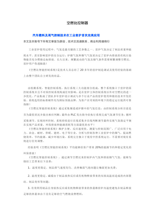
空燃比控制器汽车燃料及尾气控制技术在工业窑炉首次完美应用本文及本账号下所有文章皆为原创,技术交流请联系,商业利用请绕行工业窑炉使用过程中,气氛是最关键的工艺参数之一。
窑炉气氛决定了制品质量和能耗水平,甚至影响窑炉的安全运行;炉膛气氛和烟气气氛更决定了窑炉内排放的有机污染物能否充分燃烧达标排放。
长久以来,频繁波动的气氛及烟气条件需要频繁调整空燃比,窑炉用户伤透脑筋!《空燃比智能控制系统》是技术人员总结了20多年的窑炉制造调试及使用经验的基础上由整个团队自主研发的结晶。
由检测系统,智能控制系统,执行系统三大功能部分组成,整个系统独立于窑炉的原控制系统并且不对原控制系统构成任何影响,是在窑炉主体控制系统以外对空燃比的进一步优化。
产品集成了团队多年窑炉设计调试与多个行业产品的窑炉使用和烧结技术开发经验。
系统选用的标准硬件均为国际顶级品牌,为客户在苛刻的环境下的稳定运行提供可靠保障!《空燃比智能控制系统》通过采集烟道或炉膛中的气氛信息;由控制系统分析目前是否为最优状况并做出相应判断;最终由PLC发出指令给执行系统完成气氛调节任务;循环采集调节,实现闭环控制。
系统持续进行在线采集并在线判断调节最终实现气氛稳定平衡在实现产品质量、环保排放和能源消耗等方面最优的水平!《空燃比智能控制系统》维护方便、反应速度快、测量与控制范围广,广泛应用于电力、冶金、耐材、供暖、建材、电子等行业,分析与控制各种工业窑炉中的烟气,提高燃烧效率,节约能源,减少环境污染。
系统完全独立于现有中控系统运行,不需要对现有系统进行任何调整。
经验表明《空燃比智能控制系统》平均能够给客户带来20%的能源节约和稳定优化的环保排放!《空燃比智能控制系统》,通过调节空燃比来控制炉内气氛和排放烟气气氛,能够为烧结工艺带来以下改善:1,温度更稳定,制品排气速度均匀,改善釉面气泡问题让釉面更加光滑;2,温度更稳定,减缓由于制品放热反应或有机物释放带来的局部高温而造成的内部裂纹、制品变形等问题;3,有效利用制品自身放热反应或有机物释放带来的热量维持炉内温度避免在制品释放足够的热量却由于没有足够的空气燃烧浪费燃料;4,让制品释放的有机污染物在炉内有效燃烧,降低后续环保系统的运行压力,最终改善环保排放;5,在排放端应用则可以保证烟气的含氧量确保最终排放不会由于缺氧而导致污染物未充分燃烧而超标。
空燃比传感器监测
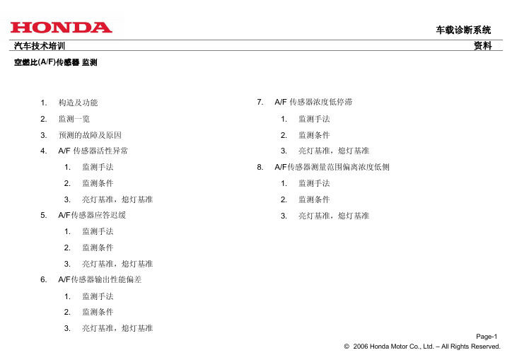
发动机油中的金属添加剂 劣质燃料中的不纯物 重复加热,冷却 重复加热,冷却 重复加热,冷却
保护器堵塞
油添加物,碳氧化所造成 的保护器的变形
加热器不升温 信号线绝缘下降 传感器偏离
重复加热,冷却 线束表皮破损 冲击,紧固转矩
各线的断线短路
配线线束,连接器,传感 器等的机械损伤
根本原因
指定外的发动机油添加剂 指定外的劣质燃料 老化,A/F异常,水分的混入 老化,A/F异常 老化,A/F异常
项目
1
发动机转速
2
发动机水温
3
吸入空气温度
4
速度
5
发动机负荷变化
6
反馈状态
检测范围
3250rpm以下 68.8℃以上 -25℃以上 41 km/h以上
应无剧烈的负荷变动 反馈中
车载诊断系统 资料
6-3.亮灯,熄灯条件 亮灯条件 2D/C检测: 在某一D/C被判定为故障时,临时DTC被存储,当下一个D/C之后的监测条件成立后被判定为故障 时,具有DTC,MIL点灯。
V6车型之例
传感器输出(mA)
倾斜大
正常范围
0
倾斜小
理论空燃比 减速断油时
浓度高
浓度低
排气气体中的氧气浓度(A/F)
Page-11 © 2006 Honda Motor Co., Ltd. – All Rights Reserved.
汽车技术培训
空燃比(A/F)传感器 监测
6-2. 监测条件 以06年雅阁机型为例,被设定为在暖机后的常速巡航行驶状态的减速时进行检测。 常速巡航行驶10秒左右后减速5秒左右检测结束,1D/C进行一次。
五线制A/F传感器
故障代 码 Bank1
燃气发动机空燃比控制系统的设计
燃气机空燃比控制系统的设计1 前言公司自主研发的燃气机气源多为来自煤矿井下的各种浓度瓦斯气,瓦斯气的浓度、压力、温度等参数会随时间发生变化,即使在保持燃气混合器中燃气阀开度不变的条件下,进入发动机的瓦斯气总量也会发生变化,导致空燃比变化。
同时,在燃气机运行时,不同的运行状态(起机、怠速、满负荷等)下所要求的空燃比也不尽相同,需要及时精确地控制空燃比。
因此空燃比控制成为气体机最关键的技术。
2 空燃比控制系统总体方案2.1 空燃比控制系统的作用空燃比控制系统能够根据燃气机混合气中瓦斯浓度的变化自动调节燃气阀和空气阀的开度,从而调节瓦斯气和空气的进气量,使燃气机空燃比在燃气浓度、压力或温度发生变化时,仍然能够保持在理想范围内,实现燃气发动机最佳空燃比控制,保证发动机稳定运行。
避免了因空燃比变化导致的发动机功率不稳、转速不稳、进气管回火和排气管放炮等现象的发生。
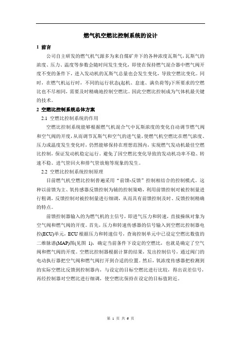
2.2 空燃比控制系统控制原理目前燃气机空燃比控制普遍采用“前馈-反馈”控制相结合的控制模式。
这种以前馈为主、氧传感器反馈控制为辅的控制策略,利用前馈控制对被控制量进行粗调,反馈控制对被控制量进行细调,从而具有前馈控制及时、反馈控制精确的特点。
前馈控制器输入的为燃气机的主信号,即进气压力和转速,直接操纵对象为空气阀和燃气阀的开度。
首先,压力和转速传感器的信号输入到空燃比控制器电控(ECU)单元,ECU根据压力和转速信号,查询控制单元中已设定空燃比数值的二维脉谱(MAP)图(见图1),确定当前条件下设定的空燃比,也就是确定了空气阀和燃气阀的开度。
空燃比控制器根据计算的结果,发出控制信号,通过阀门的电动执行器把空气阀和燃气阀打开到合适的位置。
然后,氧浓度传感器把检测到的实际空燃比反馈到控制器内,与设定的目标空燃比进行比较,得出误差信号,再经控制器对空燃比进行细调,使空燃比保持在设定的目标值附近。
图12.3 系统结构示意图3.1 空燃比控制器及系统软件燃气机的工作条件要求空燃比控制系统必须具有可靠性高、抗干扰强、响应速度快和精度高等特点,同时各种信息的采集也必须准确可靠,因此公司选择的控制器及软件为WOODWARD公司的EGS-TRIM系列。
空燃比反馈控制系统(OS)资料
5、学习空燃比控制
(1)学习空燃比变 化,不断修正调节空燃比,微调喷油量,进一步 提高空燃比的控制精度。
(2)学习空燃比控制修正范围
一般闭环控制空燃比修正系数为0.80-1.20或1.251.75,在故障诊断仪里显示为±20%或±25%。如果 修正值超出修正范围时,不再修正调节。
(1)喷油器漏油造成混合气过浓。 (2)喷油器堵塞造成混合气过稀。 (3)点火系统缺火或火花塞能量不足造成混合气 (HC和新鲜空气)直接进入三元催化器燃烧,使 得发动机动力性、经济性、排放性下降。 (4)气门正时不对,造成混合气直接进入三元催 化器燃烧。 (5)空气流量计后漏气造成NO2过多。 (6)空气流量计故障造成进气量计量不准。 (7)进气温度传感器或水温传感器故障。 (8)燃油压力调节器失效。
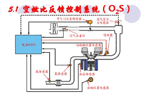
ZrO2陶瓷对氧离子浓度特别敏感,在内外有氧离 子浓度差时,氧离子由高浓度向低浓度扩散时形 成电池。
2、氧化锆式氧传感器的结构
主要由锆管、电极、保护管等组成。
3、氧化锆式氧传感器的工作原理
氧化锆式氧传感器工作原理图
工作原理:
发动机的排气气流从锆管表面的陶瓷层渗入,与 负极接触,内部的正极与大气接触。温度较高时, O2发生电离形成氧离子。若陶瓷层内(大气)、 外(废气)侧氧离子存在浓度差时,使得陶瓷体 内侧(正极)的氧离子向外侧(负极)扩散,锆 管元件形成了一个微电池,扩散的结果造成锆管 正、负极间产生电势差。 浓度差越大,电势差越大。
注意点
通过安装在排气管上的氧传感器送来的 反馈信号,对理论空燃比进行反馈控制。
3、氧传感器对喷油量的控制与修正
(1)前氧传感器对空燃比进行反馈控制。 (2)后氧传感器用于检测三元催化转换器的催化 效率。
燃气发电机组

中国在燃气发电机组唯一授权代理商, 负责在中国的发电机组和零配件的全权 销售。
三、瓦克夏燃气机组介绍
➢ 工程案例
现有珠海、海口等地垃圾 填埋厂准备使用瓦克夏燃气 发电机组,将于今年年底投 产运行。
三、瓦克夏燃气机组介绍
➢ 国外技术培训及个人工程师授权
我公司先后派技术工程师去泰国、美国 等培训基地进行培训学习,能单独进行机 组初次试车以及售后维护保养服务。
高斯科尔SFGLD560燃气机
国产燃气机
六、各种燃气机组比较
➢ 国产燃气机和国外燃气机技术参数和性能比较
六、各种燃气机组比较
➢ 国产燃气机和国外燃气机技术参数和性能比较
六、各种燃气机组比较
➢ 国产燃气机和国外燃气机技术参数和性能比较
国内目前燃气机的设计基本是在原有的柴油机的设计上进行修改,主要是新 增加火花塞点火系统,更改压缩比,和部分相关零件。生产设备都采用原有的柴油 机生产线,所以产品都带有柴油机的特性。采用V12气缸190mm×210mm,排 量达到71.5升但由于转速低,导致输出功率低,体积庞大,运动件过重,使得机组 整体效率低,机油消耗过高。由于燃气机热负荷高,气体带有一定的腐蚀性,很多 有关零件的材料要求高,零件的热处理和化学处理工艺复杂,导致原有的柴油机零 件的材料和工艺都不适应燃气机的要求。所以国产燃气机的大修期短,零件有效工 作时间不长,更换频繁,运行成本高。严重的影响在线率,年平均在线时间短,一 般只有65%左右。 在机组控制系统上,国产机500kw机组都是采用传统得柴油机控制方法。由 于沼气特别是垃圾填埋沼气是一种很不稳定的气源,工作过程中CH4 的含量,气体 总流量,压力都处于一定范围的波动,没有有效的控制能力,就无法使机组正常运 行。电压、频率、相位的波动都可能导致并网的失败,影响发电输出总量,产出低。
2.8-空燃比闭环控制
第31页,共56页。
3)闭环控制时λ的变化过程
当氧传感器输出电压越过450mV左右的门槛值跃升或跃降时, ECU确认混合气成分发生了越过λ=1的改变。此时应通过λ修正系 数调整喷油量,使混合气成分回头往λ=1方向发展。当然,最好 是一步调整到混合气λ=1并保持下去。
第24页,共56页。
片式宽带氧传感器是Nerst浓度电池(传感电池)和用于氧离子输送 的泵电池的一种结合,所以它不仅能判定λ大于1还是小于1,而且能在 稀的和浓的区域测定λ的具体数值。每个传感器要单独进行标定。
这种传感器要求专门的电子控制装置,不仅要求用于产生传 感器制 传感器温度的电子控制装置。
这段时间称为死时间,由以下四部分组成:
1. 混合气从喷油器到气缸的流动时间;
2. 发动机一个工作循环从进气到排气所经历的时间; 3. 燃烧过的气体从气缸到氧传感器的流动时间;
4. 氧传感器的响应时间。
其中主要是混合气和燃烧气体的流动时间。
第30页,共56页。
死时间的长短取决于发动机的负荷与转速。 例如怠速时根据氧传感器与发动机的距离长短,
加热的管式氧传感器可以安装在离发动机相对较远的地点, 因而长期全负荷运行时氧传感器也不会因过热而出问题。
加热的管式氧传感器始终具有最佳的工作温度,可 实现较低的和稳定的废气排放。
第20页,共56页。
4)片式氧传感器
前述的两种氧传感器的传感元件都是管状的(传感陶瓷管)。在此基础上开 发出了加热元件集成于片状传感元件的氧传感器。
这层加固层防止了铂催化层 遭受废气中沉积物的腐蚀和 侵蚀,确保了传感器的长期 稳定性。
第10页,共56页。
Altronic CD200系列数字容量放电引火系统说明书

CD20012–24 VDC POWERED IGNITION SYSTEMSn Universal, low-cost, microprocessor-based industrialsystems for 1- to 16-cylinder enginesn Programmable configuration to select the feature setappropriate to the application— Timing curves vs. RPM or analog signal — Selectable spark energy— Individual cylinder timing adjustment — Adjustable overspeed tripn Comprehensive diagnostics for troubleshooting n Windows ™-based terminal program for configurationand monitoringn Modbus RTU communications and monitoringn CSA-certified for Class I, Division 2, Groups C and D, T4when used with shielded versions of harnesses and coilsn Patented technology: U.S. Patent No. 5,623,209The Altronic CD200 Series are high energy, digital, capacitor-discharge ignition systems designed for use on 1- to 16-cylinder industrial gas engines. Available in unshielded (70 Series) and shielded (80, 90 Series), these DC-powered systems eliminate maintenance-intensive mechanical distributor ignition systems. With no moving parts, they employ microprocessor technologyto provide high-end control features and operational flexibility across the range of suitable applications.All CD200 units process angular position input signals from a magnetic pickup which senses drilled reference holes orprotrusions on a steel disc. Series 90 also supports the use of a Hall-effect pickup with a magnet disc allowing it to be used as a replacement for the Altronic DISN series. These provide accurate and consistent ignition timing referenced directly to the engine’s crankshaft or camshaft. Use of high energy, capacitor-discharge (C.D.) technology, proven in hundreds of thousands of natural gas engine applications worldwide, provides maximum engine performance and can often extend usable spark plug life by three to five times compared to an inductive ignition system.A Windows ™-based terminal program gives users access to the entire range of CD200 features, including adjustable output en-ergy, automatic timing adjustment curves (based on RPM or an analog control input such as a load sensor), and the overspeed setpoint. Using this approach, the user can implement those specific features required for a particular application. This software package also displays the system primary and secondary discharge diagnostics. For simple use in the field, these same diagnostics are available to the local opera-tor via a flashing LED on theunit. Remote communications and monitoring via Modbus-RTU are also standard.CERTIFIEDCLASS I, DIVISION 2,GROUPS C and D, T4when used with shielded80 Series (shielded)90 Series (shielded)70 Series (unshielded)Form CD200 8-17 ©2017 Altronic, LLC712 Trumbull Avenue, Girard, Ohio 44420(330) 545-9768 / Fax: (330) 545-3231Email:****************************SpecificationsNo. of cylinders ......................1-16Power required .......................12Vdc, 3.5Amp, 24Vdc, 2Amp Max. voltage output ................40kVSpark duration .......................300-600 microsec.Timing adjustment:Manual (8-pos. switch) er-selectable increments RPM range .........................25 to 2,500RPM Analog input range ..............4-20mA or 0-5Vdc Overall max. timing range .....25° of retard Overspeed setpoint range ........25 to 2,500RPM Output switch rating ...............0.5Amp, 32Vdc munications .....................Modbus RTU (RS-485)DimensionsCD200 COMPONENTS。
Altronic空燃比控制系统资料
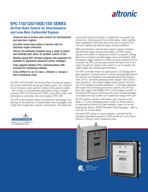
Altronic, LLC – A Member of the HOERBIGER GroupEPC-110/120/100E/150 SERIESAir/Fuel Ratio Control for Stoichiometric and Lean-Burn Carbureted EnginesnUniversal line of air/fuel ratio controls for stoichiometric and lean-burn enginesnAccurate closed-loop control of air/fuel ratio for minimum engine emissionsnPrecise full-authority actuation using a range of piston and butterfly-style valves for positive control of fuel nModbus-based EPC terminal program and expanded I/O available to implement advanced control strategies nFully supports Modbus RTU communications with included PC monitoring softwarenCSA-certified for use in Class I, Division 2, Groups C and D hazardous areasThe EPC-110/120/100E/150 Air/Fuel Ratio Controls are applica-ble to most carbureted natural gas-fueled engines. This universal line of emission control systems includes three specific models – two of them for stoichiometric applications using a catalytic converter (EPC-110/120 and EPC-100E), and a third model used exclusively on carbureted, lean-burn engines (EPC-150).The EPC control systems utilize microprocessor technology, thus allowing for the execution of sophisticated control strategies, and a high-level of application-specific customization. This advancedcontrol and setup functionality is coupled with a complete line of precision, industry-proven fuel control valves. Taken together, these capabilities collectively assure the user of long-term air/fuel ratio stability and reduced engine exhaust emissions. While stoichiometric and lean-burn engines require fundamen-tally different oxygen sensing technologies, all EPC systems operate on the basis of closed-loop control to a setpoint utilizing data from an exhaust-mounted oxygen sensor as feedback. With the exhaust oxygen setpoint for lowest emissions entered into the controller, the EPC unit precisely controls the flow of fuel to the engine through the stepper motor valve(s) so as to maintain the target oxygen level during engine operation.The EPC controllers feature an alphanumeric LCD display which gives operators continual access to critical operating data without the need for non-hazardous area approved hand-held program-mers or PC’s. Controller operating mode, stepper motor control valve position(s), and exhaust oxygen sensor value(s) are just a few of the display-accessible parameters. To facilitate integration with supervisory monitoring and control systems, the EPC sys-tems fully support the ModBus RTU communications protocol. A full-featured PC-based monitoring and control software package is included with each system at no additional charge to the user.All EPC systems operate on DC-power, with a typical current draw of 1-3 amps (depending upon model). In remote areas or on applications without DC-power available, power can be pro-vided by the Altronic 24VDC Alternator Power Packages – refer to form ALT for further details.The entire EPC family of control products is certified by theCanadian Standards Association (CSA) as safe for use in Class I, Division 2, Group C and D hazardous areas.CERTIFIEDCLASS I, DIVISION 2,GROUPS C and DAltronic Gas Control Valvesn For use with Altronic EPC-100E, EPC-110/120 and EPC-150 Air/Fuel Ratio Control Systems and suitable for other gas control applicationsn“Universal” valve designs are suitable for use on in-line or V-style, naturally-aspirated or carbureted, and stoichiometric or lean-burn natural gas enginen Sophisticated digital linear actuator used in all valve models for precise, repeatable controlnComplete, self-contained air/fuel ratio control/ monitoring system for rich-burn engines– EPC-110 is housed in a NEMA-4X weather-proof fiber glass enclosure for direct mounting – EPC-120 is functionally identical to the EPC-110, but is housed in a panel-mount enclosuren Assures maximum efficiency for 3-way catalytic converters n Single and dual-channel models for control of in-line or V-type engines– single channel can be used on V engines with one pressure regulator/carburetorn Built-in engine and catalyst temperature monitoring/ protectionThe Altronic EPC-110/120 is designed to be used with a 3-way catalytic converter on rich-burn, carbureted, natural gas engines as a means of reducing engine exhaust emissions. Based upon the EPC-100 — used on thousands of gas engines worldwide — this unique system offers effective control of the engine air/fuel ratio as well as engine and catalyst temperature monitoring. A rugged, weather-proof enclosure eliminates the need for mount-ing inside a separate control panel.The EPC-110/120 offers easy installation, maximum applica-tion flexibility, ease of operation, and air/fuel ratio stability. The control approach of the EPC-110/120 assures engine operation at the optimum lambda (exhaust oxygen) setpoint determined to be the point of maximum catalytic converter efficiency and mini-mum engine emissions. Once determined (through an analysis of the engine exhaust), it is entered into the EPC-110/120 as the control setpoint. Using a sensor in the exhaust stream to sense the O2 content, the unit begins to adjust the flow of fuel to meet the proper exhaust oxygen setpoint(s) for minimum emissions. The full-authority fuel control valve(s), mounted in the fuel line between the carburetor and the final cut regulator, assures pre-cise, repeatable control of the air/fuel ratio without resorting to the potentially dangerous strategy of adding fuel to the air intake of the engine.Monitoring and protecting the engine and catalyst from high temperature-related damage or out-of-compliance operation is a key function of the EPC-110/120 system. Critical temperatures are monitored against user-adjustable setpoints using type K thermocouples.Setpoints are tied to one of two normally-closed switch outputs for integration with a safety shutdown panel or supervisory control system. The ERROR ALARM OUTPUT is tripped for all setpoint violations associated with rich/lean control limits, oxygen sensor issues, and other values related to the control functionality. All catalyst temperature setpoint violations (pre-, post-, and differential) prompt the CATALYST TEMPERATURE OUTPUT to trip.EPC-110/120 Self-Contained Air/Fuel Ratio Control and Monitoring System for Carbureted,Stoichiometric EnginesEPC-110/120 SYSTEM DIAGRAMnDesigned to optimize the performance of 3-way catalyticconvertersn User-customizable control of target lambda setpoint(s) and controller gain adjustment, and access to additional alarm, shutdown, and emissions compliance diagnostics n Ideal for applications exhibiting ambient, load, or other operational variationsn Universal model available for control of in-line or V-type, naturally-aspirated or turbocharged enginesn Full-authority fuel control eliminates hazardous direct gas admission into the air intake of the enginen Uses inputs and outputs in EPC-100 units beginning with serial number 5713The most full-featured of the EPC series, this highly-capable system is unique in its capacity for customization and precision control of the air/fuel ratio, particularly on engines with highly dynamic ambient and/or operational conditions. The EPC-100E combines a proven control approach with the ability to tailor both the lambda setpoint and responsiveness to any excursions in the monitored air/fuel ratio.The effective, closed-loop control approach in the EPC-100 and the simplicity of installation and setup have made it the control of choice for many users worldwide. In recent years, however, many users have found it necessary or helpful to apply new air/fuel ratio control capabilities as part of a larger effort to secure more consistent or even further reduced exhaust emission levels across a range of operating conditions.The EPC-100E offers advanced, user-customizable controlparameters for the dynamic adjustment of the target O 2 setpoints and controller gains, as well as a means of inhibiting automatic control on the basis of satisfying an external parameter such as load or a post-catalyst O 2 setpoint. This is accomplished through the use of a proprietary, high-level Windows™-based software package. In the example at left, the EPC-100E target O 2 setpoint is dynamically adjusted versus load (in this case derived through an input transducer monitoring air manifold pressure). The user retains the simplicity and familiarity of the EPC-100 system if no enhanced setpoint or gain adjustment control is required, but can easily invoke such functionality if necessary. These enhanced features and capabilities are accessible only via the EPC-100E Terminal Program, their operation and configuration is essentially hidden from the user and resistant to tampering or unauthorized adjustmentEPC-100E Advanced Air/Fuel Ratio Control Systemfor Carbureted, Stoichiometric EnginesEPC-100E SYSTEM DIAGRAMEPC-110/120/100E/150 11-10 ©2010 Altronic, LLCnDesigned on the highly successful EPC-100 control platformn Applicable to both single and dual regulator, lean-burn engine configurationsn Utilizes a durable and cost-effective lean-burn oxygen sensor for positive, closed loop air/fuel ratio control n Full-authority fuel control eliminates maintenance-intensive I/Ps and direct gas admission into the air intake n Reduces engine “lug” conditions and provides accurate air/fuel ratio control at lighter engine loadsThe EPC-150 is designed for use on all in-line or V-style, lean-burn, carbureted natural gas-fueled engines. Suitable applications include the highly popular Caterpillar 3400 and 3500-series engines, Waukesha VHP-class lean-burn engines, and most Cummins and Superior models. This innovative control offers reliable, precise, and positive air/fuel ratio control, while maintaining installation and operational simplicity. It alsoincorporates a number of advanced operating features to address engine conditions specific to lean-burn operation.The EPC-150 is a closed-loop air/fuel ratio controller designed to precisely adjust fuel delivery to meet and maintain a user-entered exhaust oxygen setpoint. The exhaust oxygen level is continuously monitored by a proven and reliable, yet moderate cost lean-burn oxygen sensor. During system setup, an exhaust gas analyzer is used to determine the oxygen level at whichengine-out emissions are at their lowest, with the corresponding setpoint entered into the EPC-150 system as the control setpoint. Thus, as load and other parameters change on the engine, the EPC-150 will maintain the air/fuel ratio to meet the desired exhaust oxygen level, maintaining “in-compliance” engine performance.A number of features unique to the EPC-150 optimize the controller’s ability to manage fuel-delivery and control issues specific to lean-burn engines. The EPC-150 incorporates a unique control protocol designed to limit “lug” conditions whereby a lightly loaded lean-burn engine becomes incapable of generating sufficient turbo boost to meet the speed setpoint established by the governor. This control approach, which monitors intake air pressure both before and after the throttle plate, enables the controller to automatically offset the oxygen setpoint for richer operation and ultimately increased turbo boost pressures. With the engine operating more smoothly and achieving the necessary RPM, automatic control at the desired oxygen setpoint is then restored. As with all other EPC-150operating parameters, the point at which such an offset would be made, and its value, is fully adjustable from the keypad of the control unit or remotely using the integral RS-485 ModBus RTU communications system.EPC-150 Air/Fuel Ratio Control for Carbureted, Lean-Burn EnginesEPC-150 SYSTEM DIAGRAMCONTROLLEREPC-110-1EPC-120-1EPC-110-2EPC-120-2EPC-100E EPC-150INPUTSOxygen SensorThermocouples (Type K) Pressure SensorAnalog Voltage (0-5 V.)12––24––44–4224–OUTPUTS Fuel Valves Alarm11212121POWER REQUIREMENT 10-30 Vdc 1 Amp 10-30 Vdc 1 Amp24 Vdc 3 AmpsMOUNTING BackPanelDISPLAY Alphanumeric 2x16TEMPERATURE -40°F to +185°F / -40°C to +70°C COMMUNICATIONSModBus RTU Protocol (RS-485)Ordering InformationAFR Controller, 1-channel, back mount, stoichiometric ...........................EPC-110-1AFR Controller, 2-channel, back mount, stoichiometric ...........................EPC-110-2AFR Controller, 1-channel, panel mount, stoichiometric ..........................EPC-120-1AFR Controller, 2-channel, panel mount, stoichiometric ..........................EPC-120-2AFR Controller, 2-channel, panel mount, stoichiometric ..........................EPC-100E AFR Controller, 2-channel, panel mount, lean burn .................................EPC-150Control Valve, 1.5” NPT, below 250 HP ..............................................690154-2Control Valve, 1.5” NPT, 250-1,000 HP .............................................690154-1Butterfly Valve, 2.0” NPT, 500-1,500 HP .............................................690220-1Butterfly Valve, 2.5” NPT, 750-2,000 HP .............................................690225-1Butterfly Valve, 3.0” NPT, 1,000-3,000 HP ..........................................690230-1Accessories Kit, EPC-100E/110/120, 25 ft. cables .................................691310-1Accessories Kit, EPC-100E/110/120, 50 ft. cables .................................691310-2Accessories Kit, EPC-150, 25 ft. cables .................................................691315-1Accessories Kit, EPC-150, 50 ft. cables .................................................691315-2NOTE: Order one Accessory Kit per carburetor. One Type K thermocouple required per carburetor (not supplied in kit).691310-1 ACCESSORIES KIT Oxygen Sensor 610621Cable Assembly, Control Valve, 25 ft. .....................................................693005-1Cable Assembly, O 2 Sensor, 25 ft. ..........................................................693006-1691310-2 ACCESSORIES KITOxygen Sensor ......................................................................................610621 Cable Assembly, Control Valve, 50 ft. .....................................................693005-2Cable Assembly, O 2 Sensor, 50 ft. ..........................................................693006-2691315-1 ACCESSORIES KIT Oxygen Sensor 610813Oxygen Sensor Converter .......................................................................691207-1Pressure Sensor (qty. 2) ........................................................................691204-50Cable Assembly, Control Valve, 25 ft. .....................................................693005-1Cable Assembly, Pressure Sensor, 25 ft. (qty. 2) .....................................693008-25Cable Assembly, O 2 Sensor, 25 ft. ..........................................................693009-1691315-2 ACCESSORIES KIT Oxygen Sensor 610813Oxygen Sensor Converter .......................................................................691207-1Pressure Sensor (qty. 2) ........................................................................691204-50Cable Assembly, Control Valve, 50 ft. .....................................................693005-2Cable Assembly, Pressure Sensor, 50 ft. (qty. 2) .....................................693008-50Cable Assembly, O 2 Sensor, 50 ft. ..........................................................693009-2SpecificationsAltronic, LLC712 Trumbull Avenue, Girard, Ohio 44420Phone (330) 545-9768 FAX (330) 545-9005EPC-120/100E/150 DimensionsEPC-110 Dimensions。
燃气发动机空燃比控制系统研究与开发
山东理工大学硕士学位论文燃气发动机空燃比控制系统研究与开发RESEARCH AND DEVELOPMENT ON AIR-FUEL RATIOCONTROL SYSTEM OF GAS ENGINE研究生: 李 光 举 指导教师: 高 松 教 授申请学位门类级别: 工 学 硕 士 学科专业名称: 载运工具运用工程研究方向: 内燃机性能优化与控制论文完成日期: 2008年4月30日单位代码:10433 学 号:Y0502063密 级:分类号:U464独 创 性 声 明本人声明所呈交的论文是我个人在导师指导下进行的研究工作及取得的研究成果。
尽我所知,除了文中特别加以标注和致谢的地方外,论文中不包含其他人已经发表或撰写过的研究成果,也不包含为获得山东理工大学或其它教育机构的学位或证书而使用过的材料。
与我一同工作的同志对本研究所做的任何贡献均已在论文中作了明确的说明并表示了谢意。
研究生签名:时间:年月日关于论文使用授权的说明本人完全了解山东理工大学有关保留、使用学位论文的规定,即:学校有权保留送交论文的复印件和磁盘,允许论文被查阅和借阅;学校可以用不同方式在不同媒体上发表、传播学位论文的全部或部分内容,可以采用影印、缩印或扫描等复制手段保存、汇编学位论文。
研究生签名:时间:年月日导师签名:时间:年月日本页已使用福昕阅读器进行编辑。
福昕软件(C)2005-2010,版权所有,仅供试用。
山东理工大学硕士学位论文摘要摘 要本文首先分析了燃气发动机及其空燃比控制技术的发展背景和意义,介绍了燃气发动机及其空燃比控制技术的发展现状,针对燃气发动机空燃比控制方面存在的问题,提出了本文的主要研究内容。
论文研究了8300型气体发动机及煤层气的特点,提出了基于CMAC神经网络和PID并行控制的燃气发动机空燃比控制系统的总体设计方案,并通过Simulink仿真分析,证明了该方案的可行性。
文中详细介绍了硬件的设计方案及其工作原理,包括可编程控制器(PLC)及其扩展模块的选型、传感器的选择、步进电机及驱动器的选择、信号采集与处理电路、步进电机驱动电路、键盘电路、报警电路、显示电路及电源电路等;同时详细介绍了软件的设计及实现方法,包括主程序、初始化子程序、数据采集模块、高速计数器(HSC)子程序、脉冲串(PTO)子程序、显示模块、报警模块、按键操作模块及空燃比控制模块等。
丰田诊断技术空燃比控制原理PPT学习教案

取决于净化流入量
净化率 密度?
100+【短期燃油修正】+【长期燃油修正】 100
【Short FT】:+10%
参考
【Long FT】:+35%
基于行驶条件计算增加45%喷油量, 否则空燃比将不在14.7:1,
第26页/共66页
27
反馈(MAF 偏移)
如果总的燃油修正为+45%
基本喷油量 × 各种补偿系数 × 反馈补偿 - 净化值
etc
取决于反馈
取决于净化流入 量
净化率 密度?
下一个课题
100+【短期燃油修正】+【长期燃油修正】 100
第25页/共66页
26
反馈(MAF 偏移)
喷油量计算公式
基本喷油量 × 各种补偿系数 × 反馈补偿 - 净化值
取决于进气质量 MAF PIM
取决于工况 THW THA
etc
取决于反馈
如果每个传感器都输出正确值,空燃比应为14.7:1
第4页/共66页
5
反馈(SFT & LFT)
如何将空燃比保持在理论空燃比?
进气量为 _XX_升
基本喷油量基于进 气质量和各种补偿
影响反馈值
空燃比太浓/稀
如果反馈值指示浓/稀,传感器输出可能不正确
第5页/共66页
6
反馈(SFT & LFT)
喷油量计算公式
OL Fault 不正常 因为系统故障而停止控制
第19页/共66页
P112&31
20
反馈的相关数据流-A/F & O2
空燃比传感器和氧传感器的工作温度
传感器
A/F传感器 氧传感器
活化温度 (氧化锆)
750℃ 400℃
Altronic 控制系统 - 霍伯格集团成员说明书
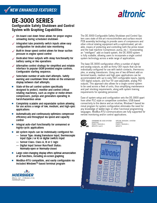
Altronic, LLC – A Member of the HOERBIGER GroupnState-of-the-art control system specificallydesigned to protect, monitor and control critical rotating machinery, such as engine or motor-driven compressors, pumps and generators operating in harsh/hazardous areasnCompletely scalable and expandable system allowing for use across a range of low, medium, and high-spec applicationsnAutomatically and continuously optimizes compressor efficiency and throughput via speed and capacity controlnIntegral auto-start functionality for unmanned or highly-cyclic applicationsnAll system inputs can be individually configured for: — Sensor Type: Analog transducer input, thermocouple input (type J or K) or digital (switch) input — Sensor Class: Class A, B or C logic— Digital Input Sensor Run/Fault Status: Normally-open or Normally-closednLarge color-changing display offers optimal annunciation of all functions, including on-screen graphingnModBus-RTU compatible, and easily configurable via included Windows TM -based terminal programThe DE-3000 Configurable Safety Shutdown and Control Sys-tem uses state-of-the-art microcontrollers and surface-mount PCB assembly technology to provide users of compressors and other critical rotating equipment with a sophisticated, yet reli-able, means of protecting and controlling both the prime mover and the load machine (compressor, pump, etc.). Incorporating an “intelligent” add-on board system, the DE-3000 system is fully scalable, allowing users to incorporate a single control system technology across a wide range of applications.The base DE-3000 configuration offers a number of digital and analog outputs, as well as thirty (30) inputs that can be individually configured for use with switch contacts, thermocou-ples, or analog transducers. Using one of two different add-on terminal boards, medium and high-spec applications can be accommodated with up to sixty (60) configurable inputs, twenty (20) digital outputs, and four (4) user-adjustable, analog PID outputs. This approach also allows for a single control system to be used across a fleet of units, thus simplifying maintenance and part stocking requirements, along with system training requirements for operating personnel.Ease of system setup and configuration sets the DE-3000 apart from other PLC-style or competitive controllers. USB-based connectivity to the device and an intuitive, Windows TM -based ter-minal program for system configuration eliminates the need for any knowledge of ladder-logic or other functional programming languages. ModBus-RTU communications are fully supported for remote monitoring and/or control applications.STANDARD DE-3000 SYSTEM CERTIFIEDCLASS I, DIVISION 2,GROUPS C and DSPECIAL DIVISION 1 SYSTEM CERTIFIEDCLASS I, DIVISION 1,GROUP D✓ On-board cool down timer allows for proper engineunloading during scheduled shutdown✓ Integrated lube proximity switch inputs allow easyconfiguration for dedicated lube monitoring ✓ Built-in linear speed control allows for linear suction pressure vs engine speed control ✓ Dedicated timer outputs with delay functionality for battery saving or like operations✓ Alternative control strategy for simplified and reliableinterface to popular OEM-provided engine controls. Configurable starting sequence.✓ Selectable number of auto-start attempts. Safetywarning and countdown timer visible on the enhanced display between start attempts.DE-3000 SERIESConfigurable Safety Shutdown and Control System with Graphing CapabilitiesDE-3000 Description and OperationThe innovative, CSA-certified DE-3000 control system compre-hensively starts, protects, monitors, and controls critical rotat-ing equipment such as reciprocating engines, compressors, and pumps. This scalable and expandable microprocessor-based system includes a Display Module, Power Supply Module and Ter-minal Module(s). Each device is typically mounted in an associ-ated control panel, with the Display Module installed for simple operator access, and the Power Supply and Terminal Module(s) DIN-rail mounted in the rear of the enclosure.System OverviewDisplay Module — System operating and appli-cation performance information such as enginespeed, monitored pressures and temperatures,and the nature of detected alarms and shut-downs is available via a robust, sixteen position,sealed-membrane keypad and 128 x 64-pixelgraphics display with multi-color backlighting.The backlight colors will change according to thecondition of the engine. The backlight colors areas follows for the given engine conditions:RED: FAULT / STOPGREEN: RU NNINGY ELLOW: TIMERS ACTIVEP U RPLE:TEST MODEThe display also has a graphing feature insteadof a bar graph. Each analog channel (includingspeed) may be viewed. The graphing screen isupdated every minute (which allows the user tosee 90 minutes of past data on the screen) andshows the most recent data to the left of thescreen. The last data is shown on the far righthand side of the screen. The graphing featurewill allow the user to view trending on the pan-el. System configuration information is storedin non-volatile memory as are the associated system datalogs. Power Supply Module — In addition to conditioning and routing the 12-24 VDC input power, the DE-3000 Power Supply Module also carries up to four (4) industry-standard, 0.6 inch, plug-in digital output modules. These optically-isolated, solid-state devices—including several Altronic-manufactured models—are typically used for on/off control of on-engine processes such as starting motors, fuel, and ignition firing.Terminal Module(s) — All system digital and analog inputsand control outputs are routed through the DE-3000 Terminal Module. Unique to the DE-3000, all system inputs are indi-vidually configurable for use as discrete (switch) inputs, thermocouple inputs (J or K), or as analog trans-ducer inputs. The base Terminal Module can beexpanded substantially through the useof one of two Expansion Modules.System OperationThe scalable and expandable nature of the DE-3000 allows it to be used on the simplest safety-shutdown-oriented applications, on mid-range applications with minimal or moderate auto-start or capacity control requirements, and on highly-complex units where a significant number of points must be monitored and functions controlled simultaneously.Safety-Shutdown Functions — At its core, the DE-3000 is an annunciator which directly monitors parameters such as tempera-tures, pressures, speeds, and vibration levels against a set of pre-set alarm and shutdown thresholds. Once detected, the DE-3000 will take the necessary actions (as configured by the user) to alert the operator and/or shutdown the engine by interrupting the flow of fuel and disabling the ignition system.Control Functions — Full auto-start capabilities, including crank-disconnect, are available in the DE-3000. On-board 4-20mA PID control outputs (up to four) and digital outputs (up to 20) offer a range of sophisticated capacity control options.In a typical operation, the DE-3000 starts and warms-up the engine/compressor, raises it to load-carrying speed, and then automatically applies the loadby actuating compressor slidevalves or other capacity controldevices. Should the controlsetpoint not be met at the min-imum load-carrying speed, thecompressor speed is automati-cally raised in an effort to meetthe desired process pressuresetpoint. This control strategyis governed by a number ofuser-adjustable load and speedlimits which can inhibit theapplication of additional load beyond what is deemed to be safe, can force the system to shed load, and can shut the engine/com-pressor down in the event that a maximum speed is exceeded. DE Series Data Logging and CommunicationsThe DE Series products are designed to operate in a communica-tion environment. The serial communications interfaces provide the user access to critical data, both locally and from remote locations, allowing predictive scheduled maintenance and/or dispatch of repair personnel with the correct parts. DE units can also initiate a call-out in the event of a fault. ModBus and ASCII protocols are supported.At the core of the DE Series communications functions are the data logs. These snapshots of data are taken at user-defined intervals and are a compilation of the analog values being moni-tored by the DE, plus unit speed, status, and complete information on the first fault that caused a system shutdown (identity, value, date, time). Using the Terminal Program, data log information can be downloaded locally to a portable PC or communicated remotely via telephone, satellite or radio. An integral data analysis/trend-ing package that is included with the DE Terminal Software candisplay and graph this data for inspection and analysis.NOTE: All inputs are configurable for discrete, analog or thermocouple input.Special DE-3000 System for Use in Class I, Division 1, Group D Hazardous AreasA special DE-3000 System has been developed for use in hazardous operating areas demanding Class I, Divi-sion 1, Group D certification. Using special DE-3000 Terminal Modules and a system Power Supply Module mounted with an integral barrier in an explosion-proof enclosure, this unique system is suitable for new applications requiring this higher level of hazardous area protection. It is also designed for a simple retrofit installation as a replacement for obsolete controlsystems, or where additional monitoring and/or control functionality is required without downgrading the haz-ardous area rating of the package.System ConfigurationThe intuitive Terminal Software program operates on a “fill-in-the-blanks” basis whereby the application is not programmed, but configured. Using an application template as a guide, and connecting to a Windows™-based PC via USB connection, the operator selects the appropriate operating parameters and setpoints for each input channel, defines the performance of the digital and analog control outputs, configures the eleven (11) service meters, and establishes the frequency of system datalog sampling and recording. This approach puts application configuration and adjustment into the hands of an educated user by eliminating any complex ladder-logic based programming and revision in the field.Form DE-3000 10-12 ©2012 Altronic, LLC712 Trumbull Avenue, Girard, Ohio 44420(330) 545-9768 / Fax: (330) 545-3231Email:***********************************General SpecificationsCOMMUNICATIONS PORTS ...............1 RS-232, 2 RS-485, USB DISPLAY ............................128 x 64-pixel, alphanumeric, backlit SCAN RATE ..........................................................3 per second AMBIENT TEMPERATURE .....–40°C to +85°C (–40°F to +185°F)POWER REQUIRED ...........12 to 24 Vdc, 15 watts max. (Std. DE)POWER REQUIRED ...........12 Vdc, 15 watts max. (DIV 1 System)HAZARDOUS AREA CERTIFICATIONStandard DE-3000 System: Class I, Division 2, Groups C and D Special Division 1-Certified System: Class I, Division 1, Group DTo OrderDISPLAY MODULEDE-3000 System .......................................................................DE-3000Division 1 DE-3000 System ...............................................DE-3000-DIV1POWER SUPPLY MODULEAll Standard DE Systems ...........................................................691122-1Division 1 DE-3000 System (incl. Ex. Box) .................................691350-1TERMINAL MODULEDE-3000 System (Standard) First Terminal Module (30 input) .........................................691171-1 Second Terminal Module (15 input) .....................................691175-2 Second Terminal Module (30 input) ....................................691171-2DE-3000 System (Division 1) First Terminal Module (30 input) .........................................691171-3 First Terminal Module (15 input) .........................................691175-3CABLE ASSEMBLIESDisplay to Terminal Module (DB-25) ..........................................693115-1Power Supply to Terminal Module (DB-25) ..................................693115-1 (Standard DE-3000 Systems Only)Power Supply to Terminal Module ...............................................693135-1 (Div. 1 Certified DE-3000 System Only)Display Module RS-232 Port (DB-9) ..........................................693116-1Expansion cable for optional added Terminal modules ..................693133-1*Use only if Power Supply and Terminal Modules are mounted separately.OUTPUT RELAY MODULES (common to all DE systems)C.D. Fuel Valve/Ignition ...............................................................6911245-48 Vdc, 5.0 A. ........................................................................6911255-60 Vdc, 2.0 A. ........................................................................6910565-200 Vdc, 0.67 A. ....................................................................69106624-280 Vac, 2.0 A. .. (691065)Available Altronic TransducersPRESSURE TRANSDUCERS0-15 psia ........................................................................691204-150-50 psia ........................................................................691204-500-100 psia .....................................................................691204-1000-300 psia .....................................................................691204-3000-500 psia .....................................................................691204-5000-100 psig/0-680 Kpa ......................................................691201-1000-300 psig/0-2040 Kpa ...................................................691201-3000-500 psig/0-3400 Kpa ...................................................691201-5000-1000 psig/0-6800 Kpa..................................................691201-10000-2000 psig/0-136 bar ....................................................691201-20000-5000 psig/0-340 bar ....................................................691201-5000TEMPERATURE TRANSDUCERSRange: +5°F to 350°F / –15°C to 176°C (±3°F / ±2°C) 1.75" length ...................................................................691202-300 5.75" length ...................................................................691203-300Range: –40°F to 450°F / –40°C to 232°C (±6°F / ±4°C) 1.75" length ...................................................................691212-450 5.75" length ...................................................................691213-450TRANSDUCER CABLES5 ft. length .............................................................................693008-525 ft. length ..........................................................................693008-2550 ft. length .........................................................................693008-50。
Altronic DISN 800点火系统
Altronic DISN 800点火系统1 概述1.1 Altronic DISN 800点火系统包含以下部分:1.DISN 800 点火单元2.霍尔效应传感器3.磁电盘4.输出电缆线束5.传感器电缆组件6.时间控制电缆组件7.点火线圈1.2 The DISN 800 系列单元可以通过应用开关来选择多达8种的工作模式。
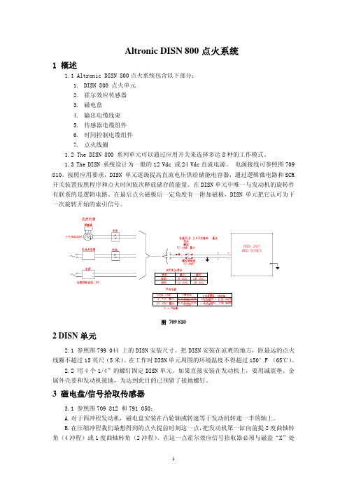
1.3 The DISN 系统设计为一般的12 Vdc 或24 Vdc直流电源。
电源接线可参照图709 810。
按照应用要求,DISN 单元逐级提高直流电压供给储能电容器,通过逻辑微电路和SCR2.1 参照图799 044 上的DISN安装尺寸。
把DISN安装在凉爽的地方,距最远的点火线圈不超过15英尺(5米)。
在工作时DISN单元周围的环境温度不得超过150°F (65℃)。
2.2 用4个1/4”的螺钉固定DISN单元。
如果直接安装在发动机上,要用减震垫。
金属外壳要和发动机接地,为达到此目的已预留了接地螺钉。
3 磁电盘/信号拾取传感器3.1 参照图709 812 和791 050:A.对于四冲程发动机,磁电盘安装在凸轮轴或转速等于发动机转速一半的轴上。
B.在压缩冲程我们最想得到的点火提前时刻这一点,把发动机第一缸向前提2度曲轴转角(4冲程)或1度曲轴转角(2冲程)。
在这一点霍尔效应信号拾取器必须与磁盘“X”处边缘成一直线。
当装上磁电盘时,必须注意它的旋转方向。
注意:对于特定发动机,当磁盘和传感器安装好后,不同于第一缸的其他缸也可正常使用。
对于特定发动机,当磁盘和传感器安装好后,必须提供一个较大的点火提前角。
C.把霍尔效应信号拾取器安装在固定的刚性支架上,保证间隙不超过0.040” (1mm)。
信号拾取器的正面也必须与磁盘的旋转中心在一直线。
见图 709 812。
3.2将传感器电缆插进点火单元的6针插座,将3针插头插入霍尔效应传感器。
图 709 8124 点火线圈4.1使用 Altronic 点火线圈。
- 1、下载文档前请自行甄别文档内容的完整性,平台不提供额外的编辑、内容补充、找答案等附加服务。
- 2、"仅部分预览"的文档,不可在线预览部分如存在完整性等问题,可反馈申请退款(可完整预览的文档不适用该条件!)。
- 3、如文档侵犯您的权益,请联系客服反馈,我们会尽快为您处理(人工客服工作时间:9:00-18:30)。
Altronic, LLC – A Member of the HOERBIGER GroupEPC-110/120/100E/150 SERIESAir/Fuel Ratio Control for Stoichiometric and Lean-Burn Carbureted EnginesnUniversal line of air/fuel ratio controls for stoichiometric and lean-burn enginesnAccurate closed-loop control of air/fuel ratio for minimum engine emissionsnPrecise full-authority actuation using a range of piston and butterfly-style valves for positive control of fuel nModbus-based EPC terminal program and expanded I/O available to implement advanced control strategies nFully supports Modbus RTU communications with included PC monitoring softwarenCSA-certified for use in Class I, Division 2, Groups C and D hazardous areasThe EPC-110/120/100E/150 Air/Fuel Ratio Controls are applica-ble to most carbureted natural gas-fueled engines. This universal line of emission control systems includes three specific models – two of them for stoichiometric applications using a catalytic converter (EPC-110/120 and EPC-100E), and a third model used exclusively on carbureted, lean-burn engines (EPC-150).The EPC control systems utilize microprocessor technology, thus allowing for the execution of sophisticated control strategies, and a high-level of application-specific customization. This advancedcontrol and setup functionality is coupled with a complete line of precision, industry-proven fuel control valves. Taken together, these capabilities collectively assure the user of long-term air/fuel ratio stability and reduced engine exhaust emissions. While stoichiometric and lean-burn engines require fundamen-tally different oxygen sensing technologies, all EPC systems operate on the basis of closed-loop control to a setpoint utilizing data from an exhaust-mounted oxygen sensor as feedback. With the exhaust oxygen setpoint for lowest emissions entered into the controller, the EPC unit precisely controls the flow of fuel to the engine through the stepper motor valve(s) so as to maintain the target oxygen level during engine operation.The EPC controllers feature an alphanumeric LCD display which gives operators continual access to critical operating data without the need for non-hazardous area approved hand-held program-mers or PC’s. Controller operating mode, stepper motor control valve position(s), and exhaust oxygen sensor value(s) are just a few of the display-accessible parameters. To facilitate integration with supervisory monitoring and control systems, the EPC sys-tems fully support the ModBus RTU communications protocol. A full-featured PC-based monitoring and control software package is included with each system at no additional charge to the user.All EPC systems operate on DC-power, with a typical current draw of 1-3 amps (depending upon model). In remote areas or on applications without DC-power available, power can be pro-vided by the Altronic 24VDC Alternator Power Packages – refer to form ALT for further details.The entire EPC family of control products is certified by theCanadian Standards Association (CSA) as safe for use in Class I, Division 2, Group C and D hazardous areas.CERTIFIEDCLASS I, DIVISION 2,GROUPS C and DAltronic Gas Control Valvesn For use with Altronic EPC-100E, EPC-110/120 and EPC-150 Air/Fuel Ratio Control Systems and suitable for other gas control applicationsn“Universal” valve designs are suitable for use on in-line or V-style, naturally-aspirated or carbureted, and stoichiometric or lean-burn natural gas enginen Sophisticated digital linear actuator used in all valve models for precise, repeatable controlnComplete, self-contained air/fuel ratio control/ monitoring system for rich-burn engines– EPC-110 is housed in a NEMA-4X weather-proof fiber glass enclosure for direct mounting – EPC-120 is functionally identical to the EPC-110, but is housed in a panel-mount enclosuren Assures maximum efficiency for 3-way catalytic converters n Single and dual-channel models for control of in-line or V-type engines– single channel can be used on V engines with one pressure regulator/carburetorn Built-in engine and catalyst temperature monitoring/ protectionThe Altronic EPC-110/120 is designed to be used with a 3-way catalytic converter on rich-burn, carbureted, natural gas engines as a means of reducing engine exhaust emissions. Based upon the EPC-100 — used on thousands of gas engines worldwide — this unique system offers effective control of the engine air/fuel ratio as well as engine and catalyst temperature monitoring. A rugged, weather-proof enclosure eliminates the need for mount-ing inside a separate control panel.The EPC-110/120 offers easy installation, maximum applica-tion flexibility, ease of operation, and air/fuel ratio stability. The control approach of the EPC-110/120 assures engine operation at the optimum lambda (exhaust oxygen) setpoint determined to be the point of maximum catalytic converter efficiency and mini-mum engine emissions. Once determined (through an analysis of the engine exhaust), it is entered into the EPC-110/120 as the control setpoint. Using a sensor in the exhaust stream to sense the O2 content, the unit begins to adjust the flow of fuel to meet the proper exhaust oxygen setpoint(s) for minimum emissions. The full-authority fuel control valve(s), mounted in the fuel line between the carburetor and the final cut regulator, assures pre-cise, repeatable control of the air/fuel ratio without resorting to the potentially dangerous strategy of adding fuel to the air intake of the engine.Monitoring and protecting the engine and catalyst from high temperature-related damage or out-of-compliance operation is a key function of the EPC-110/120 system. Critical temperatures are monitored against user-adjustable setpoints using type K thermocouples.Setpoints are tied to one of two normally-closed switch outputs for integration with a safety shutdown panel or supervisory control system. The ERROR ALARM OUTPUT is tripped for all setpoint violations associated with rich/lean control limits, oxygen sensor issues, and other values related to the control functionality. All catalyst temperature setpoint violations (pre-, post-, and differential) prompt the CATALYST TEMPERATURE OUTPUT to trip.EPC-110/120 Self-Contained Air/Fuel Ratio Control and Monitoring System for Carbureted,Stoichiometric EnginesEPC-110/120 SYSTEM DIAGRAMnDesigned to optimize the performance of 3-way catalyticconvertersn User-customizable control of target lambda setpoint(s) and controller gain adjustment, and access to additional alarm, shutdown, and emissions compliance diagnostics n Ideal for applications exhibiting ambient, load, or other operational variationsn Universal model available for control of in-line or V-type, naturally-aspirated or turbocharged enginesn Full-authority fuel control eliminates hazardous direct gas admission into the air intake of the enginen Uses inputs and outputs in EPC-100 units beginning with serial number 5713The most full-featured of the EPC series, this highly-capable system is unique in its capacity for customization and precision control of the air/fuel ratio, particularly on engines with highly dynamic ambient and/or operational conditions. The EPC-100E combines a proven control approach with the ability to tailor both the lambda setpoint and responsiveness to any excursions in the monitored air/fuel ratio.The effective, closed-loop control approach in the EPC-100 and the simplicity of installation and setup have made it the control of choice for many users worldwide. In recent years, however, many users have found it necessary or helpful to apply new air/fuel ratio control capabilities as part of a larger effort to secure more consistent or even further reduced exhaust emission levels across a range of operating conditions.The EPC-100E offers advanced, user-customizable controlparameters for the dynamic adjustment of the target O 2 setpoints and controller gains, as well as a means of inhibiting automatic control on the basis of satisfying an external parameter such as load or a post-catalyst O 2 setpoint. This is accomplished through the use of a proprietary, high-level Windows™-based software package. In the example at left, the EPC-100E target O 2 setpoint is dynamically adjusted versus load (in this case derived through an input transducer monitoring air manifold pressure). The user retains the simplicity and familiarity of the EPC-100 system if no enhanced setpoint or gain adjustment control is required, but can easily invoke such functionality if necessary. These enhanced features and capabilities are accessible only via the EPC-100E Terminal Program, their operation and configuration is essentially hidden from the user and resistant to tampering or unauthorized adjustmentEPC-100E Advanced Air/Fuel Ratio Control Systemfor Carbureted, Stoichiometric EnginesEPC-100E SYSTEM DIAGRAMEPC-110/120/100E/150 11-10 ©2010 Altronic, LLCnDesigned on the highly successful EPC-100 control platformn Applicable to both single and dual regulator, lean-burn engine configurationsn Utilizes a durable and cost-effective lean-burn oxygen sensor for positive, closed loop air/fuel ratio control n Full-authority fuel control eliminates maintenance-intensive I/Ps and direct gas admission into the air intake n Reduces engine “lug” conditions and provides accurate air/fuel ratio control at lighter engine loadsThe EPC-150 is designed for use on all in-line or V-style, lean-burn, carbureted natural gas-fueled engines. Suitable applications include the highly popular Caterpillar 3400 and 3500-series engines, Waukesha VHP-class lean-burn engines, and most Cummins and Superior models. This innovative control offers reliable, precise, and positive air/fuel ratio control, while maintaining installation and operational simplicity. It alsoincorporates a number of advanced operating features to address engine conditions specific to lean-burn operation.The EPC-150 is a closed-loop air/fuel ratio controller designed to precisely adjust fuel delivery to meet and maintain a user-entered exhaust oxygen setpoint. The exhaust oxygen level is continuously monitored by a proven and reliable, yet moderate cost lean-burn oxygen sensor. During system setup, an exhaust gas analyzer is used to determine the oxygen level at whichengine-out emissions are at their lowest, with the corresponding setpoint entered into the EPC-150 system as the control setpoint. Thus, as load and other parameters change on the engine, the EPC-150 will maintain the air/fuel ratio to meet the desired exhaust oxygen level, maintaining “in-compliance” engine performance.A number of features unique to the EPC-150 optimize the controller’s ability to manage fuel-delivery and control issues specific to lean-burn engines. The EPC-150 incorporates a unique control protocol designed to limit “lug” conditions whereby a lightly loaded lean-burn engine becomes incapable of generating sufficient turbo boost to meet the speed setpoint established by the governor. This control approach, which monitors intake air pressure both before and after the throttle plate, enables the controller to automatically offset the oxygen setpoint for richer operation and ultimately increased turbo boost pressures. With the engine operating more smoothly and achieving the necessary RPM, automatic control at the desired oxygen setpoint is then restored. As with all other EPC-150operating parameters, the point at which such an offset would be made, and its value, is fully adjustable from the keypad of the control unit or remotely using the integral RS-485 ModBus RTU communications system.EPC-150 Air/Fuel Ratio Control for Carbureted, Lean-Burn EnginesEPC-150 SYSTEM DIAGRAMCONTROLLEREPC-110-1EPC-120-1EPC-110-2EPC-120-2EPC-100E EPC-150INPUTSOxygen SensorThermocouples (Type K) Pressure SensorAnalog Voltage (0-5 V.)12––24––44–4224–OUTPUTS Fuel Valves Alarm11212121POWER REQUIREMENT 10-30 Vdc 1 Amp 10-30 Vdc 1 Amp24 Vdc 3 AmpsMOUNTING BackPanelDISPLAY Alphanumeric 2x16TEMPERATURE -40°F to +185°F / -40°C to +70°C COMMUNICATIONSModBus RTU Protocol (RS-485)Ordering InformationAFR Controller, 1-channel, back mount, stoichiometric ...........................EPC-110-1AFR Controller, 2-channel, back mount, stoichiometric ...........................EPC-110-2AFR Controller, 1-channel, panel mount, stoichiometric ..........................EPC-120-1AFR Controller, 2-channel, panel mount, stoichiometric ..........................EPC-120-2AFR Controller, 2-channel, panel mount, stoichiometric ..........................EPC-100E AFR Controller, 2-channel, panel mount, lean burn .................................EPC-150Control Valve, 1.5” NPT, below 250 HP ..............................................690154-2Control Valve, 1.5” NPT, 250-1,000 HP .............................................690154-1Butterfly Valve, 2.0” NPT, 500-1,500 HP .............................................690220-1Butterfly Valve, 2.5” NPT, 750-2,000 HP .............................................690225-1Butterfly Valve, 3.0” NPT, 1,000-3,000 HP ..........................................690230-1Accessories Kit, EPC-100E/110/120, 25 ft. cables .................................691310-1Accessories Kit, EPC-100E/110/120, 50 ft. cables .................................691310-2Accessories Kit, EPC-150, 25 ft. cables .................................................691315-1Accessories Kit, EPC-150, 50 ft. cables .................................................691315-2NOTE: Order one Accessory Kit per carburetor. One Type K thermocouple required per carburetor (not supplied in kit).691310-1 ACCESSORIES KIT Oxygen Sensor 610621Cable Assembly, Control Valve, 25 ft. .....................................................693005-1Cable Assembly, O 2 Sensor, 25 ft. ..........................................................693006-1691310-2 ACCESSORIES KITOxygen Sensor ......................................................................................610621 Cable Assembly, Control Valve, 50 ft. .....................................................693005-2Cable Assembly, O 2 Sensor, 50 ft. ..........................................................693006-2691315-1 ACCESSORIES KIT Oxygen Sensor 610813Oxygen Sensor Converter .......................................................................691207-1Pressure Sensor (qty. 2) ........................................................................691204-50Cable Assembly, Control Valve, 25 ft. .....................................................693005-1Cable Assembly, Pressure Sensor, 25 ft. (qty. 2) .....................................693008-25Cable Assembly, O 2 Sensor, 25 ft. ..........................................................693009-1691315-2 ACCESSORIES KIT Oxygen Sensor 610813Oxygen Sensor Converter .......................................................................691207-1Pressure Sensor (qty. 2) ........................................................................691204-50Cable Assembly, Control Valve, 50 ft. .....................................................693005-2Cable Assembly, Pressure Sensor, 50 ft. (qty. 2) .....................................693008-50Cable Assembly, O 2 Sensor, 50 ft. ..........................................................693009-2SpecificationsAltronic, LLC712 Trumbull Avenue, Girard, Ohio 44420Phone (330) 545-9768 FAX (330) 545-9005EPC-120/100E/150 DimensionsEPC-110 Dimensions。
