KB-1B开发板使用说明V3.0
芯驿 ax7z010b 开发板 用户手册说明书
文档版本控制目录文档版本控制 (2)一、开发板简介 (6)二、AC7Z010核心板 (8)(一)简介 (8)(二)ZYNQ芯片 (9)(三)DDR3 DRAM (11)(四)QSPI Flash (14)(五)时钟配置 (16)(六)电源 (17)(七)结构图 (18)(八)连接器管脚定义 (19)三、扩展板 (23)(一)简介 (23)(二)CAN通信接口 (24)(三)485通信接口 (24)(四)千兆以太网接口 (25)(五)USB2.0 Host接口 (27)(六)USB转串口 (28)(七)AD输入接口 (29)(八)HDMI输出接口 (30)(九)MIPI摄像头接口(仅AX7Z020使用) (32)(十)SD卡槽 (33)(十一)EEPROM (34)(十二)实时时钟 (34)(十三)温度传感器 (35)(十四)JTAG接口 (36)(十五)用户LED灯 (36)(十六)用户按键 (37)(十七)扩展口 (38)(十八)供电电源 (40)(十九)底板结构图 (41)芯驿电子科技(上海)有限公司 基于XILINX ZYNQ7000开发平台的开发板(型号: AX7Z010B )2022款正式发布了,为了让您对此开发平台可以快速了解,我们编写了此用户手册。
这款ZYNQ7000 FPGA 开发平台采用核心板加扩展板的模式,方便用户对核心板的二次开发利用。
核心板使用XILINX 的Zynq7000 SOC 芯片的解决方案,它采用ARM+FPGA SOC 技术将双核ARM Cortex-A9 和FPGA 可编程逻辑集成在一颗芯片上。
另外核心板上含有2片共512MB 高速DDR3 SDRAM 芯片和1片256Mb 的QSPI FLASH 芯片。
在底板设计上我们为用户扩展了丰富的外围接口,比如2路CAN 通信接口,2路485通信接口,2路XADC 输入接口, 1路千兆以太网接口,1路USB2.0 HOST 接口,1路HDMI输出接口,Uart 通信接口,SD 卡座,40针扩展接口等等。
AC7021B 开发板 用户手册说明书
文档版本控制目录文档版本控制 (2)(一)简介 (4)(二)ZYNQ芯片 (5)(三)DDR3 DRAM (7)(四)QSPI Flash (11)(五)eMMC Flash (12)(六)时钟配置 (14)(七)USB转串口 (15)(八)LED灯 (16)(九)复位按键 (18)(十)JTAG接口 (18)(十一)拨码开关配置 (19)(十二)电源 (20)(十三)结构图 (21)(十四)连接器管脚定义 (22)(一) 简介AC7021B(核心板型号,下同)核心板,ZYNQ 芯片是基于XILINX 公司的ZYNQ7000系列的XC7Z020-2CLG484I 。
ZYNQ 芯片的PS 系统集成了两个ARM Cortex™-A9处理器,AMBA®互连,内部存储器,外部存储器接口和外设。
ZYNQ 芯片的FPGA 内部含有丰富的可编程逻辑单元,DSP 和内部RAM 。
这款核心板使用了2片SK Hynix 公司的H5TQ4G63AFR-PBI 这款DDR3芯片,每片DDR 的容量为4Gbit ;2片DDR 芯片组合成32bit 的数据总线宽度,ZYNQ 和DDR3之间的读写数据时钟频率高达533Mhz ;这样的配置,可以满足系统的高带宽的数据处理的需求。
为了和底板连接,这款核心板的4个板对板连接器扩展出了PS 端的USB 接口,千兆以太网接口,SD 卡接口及其它剩余的MIO 口。
以及PL 端的BANK13, BANK33, BAN34和BANK35的几乎所有IO 口(198个),其中BANK33和BANK34的IO 的电平可以通过更换核心板上的LDO 芯片来修改,满足用户不用电平接口的要求。
对于需要大量IO 的用户,此核心板将是不错的选择。
而且IO连接部分,ZYNQ 芯片到接口之间走线做了等长和差分处理,并且核心板尺寸仅为60*60(mm ),对于二次开发来说,非常适合。
AC7021B 核心板正面图AC7021B 核心板背面图(二) ZYNQ 芯片开发板使用的是Xilinx 公司的Zynq7000系列的芯片,型号为XC7Z020-2CLG484I 。
开发板使用说明书
开发板使用说明书(, 2006-07-01)TCP/IP 1 开发板的环境建立和测试 (3)1.1 开发环境的连线步骤 (3)1.1.1 电源连接 (3)1.1.2 网线连接 (3)1.1.3 串口延长线 (4)1.2 开发环境的配置步骤 (4)1.2.1 设置IP (4)1.2.2 运行sockettest程序 (5)1.2.3 关闭防火墙 (6)1.3 开启网络监听程序 (7)1.4 开发板板开启步骤 (8)1.5 开发板板实验结果 (8)1.5.1 向PC机连接和发送数据 (8)1.5 2 Ping测试 (8)1.5.3 PC机发起连接测试 (9)1.5.4 查看Sniffer监听结果 (9)1.5.5 测试速度的方法 (10)2 出现问题时的测试步骤及程序 (10)2.1 测试单片机是否工作 (10)2.2 测试单片机串口是否工作正常 (10)2.3 测试8019和单片机的连接无误 (11)2.4 网络数据包发送测试 (11)2.5 内存测试 (11)开发板在发送给用户之前都已经调试通过,只要连接正确就可以实现TCP/IP 连接。
本文档帮助用户完成环境的搭建与进行测试。
1 开发板的环境建立和测试1.1 开发环境的连线步骤1.1.1 电源连接开发板需要5V 的直流电源。
将其插头连接到开发板的电源插座(图中○1)。
注意保证插头中心为正极,外面为负极。
1.1.2 网线连接将网线连接到电路板上的网线插座RJ45接头(图中○2)。
注意如果是和PC 机直接连接的网线,应该用交叉线(或者称为直连线);否则用一般的网线即可。
请保证网线能够连接TCP/IP 123TCP/IP到PC 。
1.1.3 串口延长线用串口延长线(一端为针、一段为孔的串口线),将开发板的串口(图中○3)连接到计算机的串口。
的默认程序不会在串口输出信息(为了使得程序运行速度更快),但是串口可以用于调试。
1.2 开发环境的配置步骤1.2.1 设置IP开发板默认程序将开发板的IP 设置如下: IP 地址 192.168.2.13子网掩码 255.255.255.0PC 机IP 192.168.2.14为了使得开发板和PC 机能够正常连接,必须保证PC 机和开发板处于一个子网中。
黑金动力II代用户手册v3.0

FPGA黑金开发板用户手册v3.0黑金动力社区 修订历史说明:本文档是针对黑金动力Ⅱ开发板的用户手册,Ⅰ版硬件和Ⅱ版硬件的差别请参考文档末尾附录B的“硬件特殊说明”.官方网站发布的教程主要针对新版开发板.- 2 -FPGA黑金开发板用户手册学习建议本产品教程专注于NIOS Ⅱ嵌入式开发,主要由C语言开发,因此,打好C语言的基础很重要,在此推荐一本《C程序设计语言》(第2版),英文名为《The C Programming Language》(Second Edition),该书是由C语言的设计者Brian W.Kernighan和Dennis M.Ritchie编写的一部介绍标准C语言及其程序设计方法的权威性经典著作。
全面、系统地讲述了C语言的各个特性及程序设计的基本方法,包括基本概念,类型和表达式、控制流、函数与程序结构、指针与数组、结构、输入与输出、UNIX系统接口、标准库等内容。
当然,结合《NIOS Ⅱ那些事儿》也是一个不错的选择,本教程紧密结合黑金开发板,由简入深,循序渐进,针对各个模块进行实例分析教学.- 3 -黑金动力社区目录Chapter 1 主要器件及特性 ............................................................................ - 5 - Chapter 2 开关,按键与数码管 ....................................................................... - 8 - Chapter 3 点阵型液晶显示器(LCD)........................................................... - 11 - Chapter 4 VGA接口 ..................................................................................... - 15 - Chapter 5 PS/2 鼠标键盘接口................................................................... - 19 - Chapter 6 RS-232 串行接口 ...................................................................... - 22 - Chapter 7 USB接口及芯片 ......................................................................... - 24 - Chapter 8 LAN接口与芯片......................................................................... - 27 - Chapter 9 RTC时钟芯片.............................................................................. - 30 - Chapter 10 高速同步SDRAM ................................................................... - 31 - Chapter 11 扩展板接口 ............................................................................... - 33 - Chapter 12 JTAG/AS下载与调试接口...................................................... - 35 - 附录A ................................................................................................................ - 37 - 附录B ................................................................................................................ - 41 - 附录C ................................................................................................................ - 42 -- 4 -FPGA黑金开发板用户手册Chapter 1 主要器件及特性本手册中描述了”黑金动力”系列开发板的设计原理和使用方法,作为开发板的配套说明材料.这套开发板主要是面向FPGA的初级,中级开发人员,或者对FPGA感兴趣的爱好者,偏向个人用户.这套开发板采用核心板与扩展板分离的方式,简单实用,扩展性好,特别适合爱好者的快速入门和开发人员的产品开发验证,也适合做更深入的IC前端设计.在这套开发板上,一切皆有可能.同时,这套开发板也提供了一个SOPC平台,可以实现嵌入式的软核,如NIOSII,Open RISC等,为嵌入式电子产品的设计开发提供了又一种选择.主要元器件介绍Altera Cyclone Ⅱ系列FPGA核心板配置的FPGA芯片是Cyclone Ⅱ系列的EP2C8Q208C更详细可到:/literature/lit-cyc2.jsp下载官方手册- 5 -黑金动力社区 - 6 -● 64Mbit 的SDRAM核心板同时配备了高达64Mbit 的SDRAM,对于运行NIOS Ⅱ的软核提供了有力的保障,这款芯片的时钟频率有143MHz,实验证明,NIOS Ⅱ可以稳定地运行120MHz,速度还是相当快的. ● 16Mbit 的配置芯片核心板还配备了16Mbit 的配置芯片,不仅可以储存配置信息,同时可以实现NIOS Ⅱ软件程序存储.● 20MHz 的有源晶振20M 的有源晶振为整个系统提供了时钟源泉.● ENC28J60网口芯片实现开发板与以太网之间的通信实验. ● USB 2.0高速数据接口采用应用广泛,性能稳定的CH376芯片,实现了开发板USB 接口的扩展,便于与计算机进行高速数据通信. ● 板载128*64的点阵LCD采用ST7565P 控制芯片,内置DC/DC 电路,可以通过串行,并行进行通信. ● 实时时钟芯片(RTC)配置DS1302芯片,增加了主电源/后背电源双电源引脚,同时提供了对后背电源进行涓细电流充电的能力. ● EEPROM配置24LC04芯片,24LC04是512*8bit 的EEPROM,支持IIC 接口. ● PS/2鼠标,键盘接口标准的鼠标,键盘接口,支持3.3V 和5V 设备,可以 用来验证PS/2接口协议. ● 9针RS-232串口实现与计算机的数据通信,辅助调试. ● VGA 接口标准VGA 接口,可直接与显示器连接,用于验证VGA 时序. ● 5个独立按键可以与液晶配合,实现完美的人机界面.FPGA黑金开发板用户手册开发板示意图核心板扩展板- 7 -黑金动力社区 Chapter 2 开关,按键与数码管按键在绝大多数电子电气设备中都存在身影,可以说,如果说显示屏是人与机器之间沟通的窗户的话,按键就是沟通的桥梁,通过按键,可以方便快捷地对机器进行操作控制.在黑金开发板中,我们设置了5个按键,分别为上,下,左,右,确认,用户可以自行设定按键的功能.电源开关电源接口及开关位于核心板左上方,如图其中F1为限流1.1A的F110保险管,在电源的保护上起到了很大的作用按键核心板上的复位电路- 8 -FPGA黑金开发板用户手册该复位电路可以实现对开发板的初始化作用,防止程序陷入死循环.扩展板上的按键扩展板上搭配有5个按键,可以满足大多数场合的设计需要,采用低电平闭合电路.按键开关管脚映射表LEDs在核心板上设置了4个LED,可以作为测试使用,电路如图- 9 -黑金动力社区LED管脚映射表数码管在扩展板上设有6位独立共阳数码管,实验证明数码管在诸多设计开发中起到了不可代替的作用.数码管的电路如图该电路图为第一位数码管的电路,其他的电路与之类似.其中,每个数码管都通过一个9012三极管放大电流,保证其亮度均匀.数码管管脚映射表- 10 -Chapter 3 点阵型液晶显示器(LCD)在扩展板的右方包括了一块128*64像素的液晶显示器,带有少见的白色背光.常见的LCD模块有LCM(玻璃),背光,PCB板,三种之中LCM(玻璃)模块必不可少,有无背光,有无PCB用户可以根据需要自行选择.点阵的LCD模块按驱动控制器的集成方式分成两种:COB和COG,COG是将驱动控制芯片集成到了玻璃里面,用户只需在电路板上加上无法集成的电阻电容即可实现对LCD的控制;而COB则需要将驱动芯片焊接在LCD 模块后面的PCB板上.黑金开发板上提供的LCD使用的是COG液晶,它将驱动控制IC集成到了LCM上,这样就省去了PCB底板,节省了很大的空间.该LCD的驱动芯片为ST7565P,支持三种接口方式,通常采用串行时序方式,接口简单,使用方便.LCD的原理图LCD的管脚映射表LCD参数注意:该LCD的显存存在8(page)*8+1行,即65行,s0-s131列,即132列,与标准的128*64液晶有的差异,该LCD的最后一行(page8的D0)和最后三列(ADC为正常时,s129,s130,s131;ADC为反向时,s0,s1,s2)是不能显示的,而显存上其他数据与LCD 上的点一一对应,具体如下图红圈所示显示屏上的每个点都对应控制器片内显示缓存RAM中的一个位,显示屏上的64*128个点分别对应显示RAM的8个Page,每个Page有128 Byte的空间对应,如图所示用户如果要点亮LCD屏幕上的某一个点时,实际上就是对该点所对应的显示RAM 区中的某一个位进行置1操作;所以就要确定该点所在的行地址,列地址.由上图可以看出,液晶的行地址实际上就是Page的信息,每个Page应有8行;而列地址表示该点的横坐标,在屏上为从左到右排列,Page中的一个Byte对应的是一列(8行,即8个点),一共128列.可以根据这样的关系在程序中控制LCD屏幕的显示.在LCD上显示字符,不管是中文还是英文,都需要字库的支持,在有些LCD模块中,已经将字库烧写在芯片当中,这样的字库有优点也有缺点.优点是操作简单,而缺点是不灵活,显示效果不好,扩展性差,而且性价比不高.黑金开发板所选用的COG屏幕是不带字库的.Chapter 4VGA接口VGA(Video Graphics Array)接口,也叫D-Sub接口,是显示卡上输出模拟信号的接口,显卡所处理的信息最终都要输出到显示屏上显示,显卡的输出接口就是电脑与显示屏之间桥梁,它负责向显示器输出相应的图像信号.CRT显示器因为设计制造上的原因,只能接受模拟信号,这就需要显卡能够输入模拟信号,于是就有了VGA接口.虽然液晶显示器可以直接接接收数字信号,但是为了兼容性,大多数液晶显示器也配备了VGA接口模块.VGA是IBM在1987年随PS/2机一起推出的一种视频传输标准,具有分辨率高,显示速率快,颜色丰富等优点,在彩色显示器领域得到了广泛的应用.目前VGA技术的应用还主要基亍VGA显示卡的计算机,笔记本等设备.根据分辨率不同,VGA分为VGA (640x480),SVGA(800x600),XGA(1024x768),SXGA(1280x1024)等.虽然说VGA的标准对于现在的个人计算机市场十分过时,但是VGA仍然是所有制造商所支持的最低标准,例如不管所有厂商的显卡,在不安装自己驱动的情况下,都是支持VGA 标准显示的.VGA接口是一种D型接口(D-SUB),上面共有15个针孔,分成三排,每排五个,如图所示.VGA引脚定义引脚1,2,3分别为红绿蓝三基色模拟电压,为0~0.714V peak-peak(峰-峰值),0V代表无色,0.714V代表满色.一些非标准显示器使用的是1Vpp的满色电平.HSYNC与VSYNC分别为行数据同步与帧数据同步,为TTL电平.黑金开发板的扩展板上配备了一个VGA接口,其电路为VGA管脚映射表VGA的时序介绍VGA的时序如图所示,它分为行数据时序和帧数据时序行数据时序为显示一行数据的时序,由上图可看出,显示一行数据需要处理两件事情:第一,产生行同步HSYNC.不难看出HSYNC是一个脉冲信号,该信号周期为:e=a+b+c+d,低电平时间为a.其中a,b,c,d均为时间信号,这些信号根据需要显示的分辨率的不同而不同.第二,产生显示的数据(DATA)信号,此信号为模拟信号,当在显示有效数据(Active Video)内,DATA信号为0~0.714Vpp的模拟电压(R,G,B),根据分辨率的不同,DATA的采样率,点数也不同.帧数据时序与行数据时序类似,是显示一个屏数据的时序.只是这里的基本单位为每行数据,而行数据里面的最基本单位为每个点.下表列出常用分辨率及时间参数Chapter 5 PS/2鼠标键盘接口PS/2 原是“Personal System 2”的意思,“个人系统2”,是IBM公司在上个世纪80年代推出的一种个人电脑。
定制最简linux和根文件系统(平台龙芯1B开发板)

定制最简linux和根文件系统(平台龙芯1B开发板)版本历史1. 前言 (5)1.1. 开发板版本号 (7)1.2. 工具链版本号 (8)1.3. 参考文档及其版本号 (8)1.4. 目标 (9)2. 搭建开发环境 (9)3. 制作根文件系统 (11)3.1. 配置 (11)3.1.1. 拷贝源码,并解压 (11)3.1.2. 配置选项简述 (12)3.2. 编译 (13)3.3. 构建根文件系统 (15)3.3.1. 建立系统根目录 (15)3.3.2. 建立设备文件 (16)3.3.3. 建立系统配置文件 (16)4. 编译linux (22)4.1. 配置 (23)4.1.1. 首先拷贝源码,并解压 (23)4.1.2. 不安装Ncurses (24)4.1.3. 没有拷贝.config (24)4.1.4. 不用修改Makefile (25)4.1.5. 配置选项简述 (26)4.2. 编译 (30)5. 启动运行linux (31)5.1. 拷贝vmlinux到tftp服务器目录下 . 315.2. 设置PMON的ip地址 (31)5.3. 下载内核 (32)5.4. 启动linux (33)1.前言很高心拿到了龙芯1B开发板。
然后仔细的看了开发板光盘里的《1B开发板用户手册.pdf》。
里面写得非常详细,并且都附有截图,很明了。
从最开始装虚拟机到编译linux,制作根文件系统等等,连虚拟机软件和Ubuntu系统镜像都有。
可以说这套开发板考虑得非常周到。
然后我就参照《1B开发板用户手册.pdf》编译了linux,制作了根文件系统,最后终于跑起来,进入了shell。
这里谈谈我的感想用户手册更像一个工具书就拿根文件系统来说吧。
Cramfs,Jffs2,Yaffs2的制作步骤都有,这表示该手册很全面,但是如果是一个初学者的话,给的选择太多不一定是好事。
这也是我想写这篇文档的原因。
我想linux 的配置尽量简单(除了串口驱动以外,其它的比如,网卡,声卡,触屏等都暂时不需要),根文件系统也尽量简单(手册中的已经很简单了,后面我们就参照手册),另外为了再简单一点我把根文件系统也选择内存文件系统,内核只下载到内存而不烧写到flash,同时PMON参数也不修改。
黑金 AX7020 开发板 用户手册说明书

文档版本控制版权申明:本手册版权归属芯驿电子公司(上海)有限公司所有, 并保留一切权力。
非经本公司(书面形式),同意,任何单位及个人不得擅自摘录或修改本手册部分或全部内容,违者我们将追究其法律责任。
感谢您购买黑金开发板,在使用产品之前,请仔细地阅读该手册并且确保知道如何正确使用该产品,不合理的操作可能会损坏开发板,使用过程中随时参考该手册以确保正确使用。
此手册不断更新中,建议您使用时下载最新版本。
软件版本:本手册使用Xilinx官方提供的Vivado版本,请从Xilinx网站下载正确的版本和使用我们提供的软件版本安装。
黑金官网:黑金动力社区:黑金官方淘宝店:联系方式:************目录一、简介 (6)二、结构尺寸 (8)三、电源 (8)四、Z YNQ7000 (10)1)JTAG接口 (12)2)FPGA供电系统 (13)3)ZYNQ启动配置 (14)五、时钟配置 (14)5.1PS系统时钟源 (14)5.2PL系统时钟源 (15)六、P S端的外设 (16)6.1QSPI F LASH (16)6.2DDR3DRAM (17)6.3千兆以太网接口 (21)6.4USB2.0 (24)6.5USB转串口 (25)6.6SD卡槽 (27)6.7PS PMOD连接器 (28)6.8用户LED (29)6.9用户按键 (30)七、P L端的外设 (31)7.1HDMI接口 (31)7.2EEPROM24LC04 (33)7.3实时时钟DS1302 (34)7.4扩展口J10 (36)7.5扩展口J11 (38)7.6用户LED (41)7.7用户按键 (42)黑金基于XILINX ZYNQ7000开发平台的开发板2016款正式发布了,型号为:AX7020 。
此款开发平台是XILINX 的Zynq7000 SOC 芯片的解决方案。
它采用ARM+FPGA SOC 技术将双核ARM Cortex-A9 和FPGA可编程逻辑集成在一颗芯片上。
ARMFLY STM32F103ZE-EK 开发板 说明书
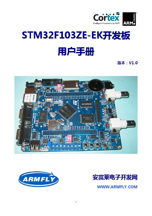
S T M32F103Z E-E K开发板用户手册版本:V1.0安富莱电子开发网W W W.A R M F L Y.C O M1.产品规格简介STM32F103ZE-EK开发板以STM32F103ZET6(LQFP144)为核心。
STM32F103ZE 是ST(意法半导体)公司推出的ARM Crotex-M3产品线中功能最强大的一款CPU。
片内集成512kB Flash、64kB RAM、1个USB、1个CAN、 8个定时器、5个USART、3个ADC、2个DAC、3个SPI、2个I2C、2个I2S、1个SDIO、112个GPIO、FSMC总线(支持NOR,NAND,SRAM)。
CPU主频72MHz,广泛适用于各种应用场合。
本开发板具备丰富的硬件资源,配套的试验例程均提供源代码,文档齐备,非常适合于学习和项目评估。
硬件资源■ 8M晶振作为MCU的时钟,32768晶振用于RTC ■ 1M字节SRAM,16M字节NOR Flash,128M字节NADN Flash■ 2M字节串行Flash,256字节串行EEPROM■ 1个SD/MMC卡座■ 1个CAN2.0A/B接口■ 2个RS232串口■ 1个RS485接口■ 1个USB2.0全速DEVICE接口■ 1个USB2.0全速HOST接口■ 1个100M/10M以太网接口■ I2S音频DAC(24bit,96kHz),1个立体声耳机插座,1个扬声器■ 3.0寸TFT真彩触摸LCD(WQVGA,400x240)■ 1个5向摇杆,1个Reset按钮、1个wakeup按钮、1个自定义按钮 ■ 4个自定义LED,1个电源LED,1个音频LED ■ 1个CR1220电池座■ 1个精密可调电阻连接到ADC输入■ 所有的GPIO引到2.54mm间距焊盘■ 1个DAC引出端子,1个PWM引出端子■ 标准2.54mm间距JTAG插座■ 2个BNC输入端子,集成双通道示波器电路,具备AC/DC切换、输入增益切换开关■ 3种供电方式:USB电缆、外接5V电源、JTAG 调试接口(J-LINK仿真器)■ 1个电源开关,上下电时无需拔插电缆■ 3种启动方式:用户Flash、系统存储器、SRAM ■ 用拨码开关取代跳线帽,避免跳线帽丢失■ 板子规格:14cm x 12cm软件资源■ 提供100多个试验例程■ 提供uCOS_II+ucGUI例程和文档■ 即将展开USB虚拟示波器项目源码■ 即将移植ucLinux (硬件资源已满足要求) ■ 更多的软件资源将在发布标配清单■STM32F103ZE-EK开发板1块■ 3.0寸TFT触摸显示模块1块■1根串口线、1根网线、1根USB电缆■资料光盘1张可选的配件:■60M示波器探头1对■USB转串口线1根2.快速入门2.1.注意事项(1)外接电源必须是5.0V 的直流电源,插头有极性,内正外负。
奋斗开发板V3.1入门手册

硬件篇:
奋斗版 STM32 开发板 V3.1 板,可选配奋斗嵌入式开发工作室的 2.4 寸(240X320)TFT 显示器、3 寸(240X400)TFT 显示器,4.3 寸(480X272)TFT 显示器及 7 寸(800X480)显 示方案。外接电源都是 5V,在学习过程中,可以用所配的 USB 线通过电脑给板子提供电源。 但也有可能由于一些电脑的 USB 供电能力太弱,提供不了足够的电流,此时就需要外接 5V 电源给板子供电了,否则会造成板子工作不正常的现象。V3 板可以通过电源插座提供 5V 接 口。 请配合原理图及硬件手册来了解奋斗 STM32 开发板的详细资源。
奋斗嵌入式开发工作室
奋斗版 STM32 开发板文档
奋斗开发板配 4.3 寸 TFT 显示器: 该模块是奋斗版 STM32 开发板 V3 及 MINI 板的配套模块,采用 STM32 的 FSMC 接口模式。
SSD1963 作为控制驱动器,显示速度更快。4.3 寸屏, 分辨率 480X272, 64K 色,数据接 口 16 位, 背光驱动采用白光驱动器提供背光用的横流源, 使背光更加均匀,背光明暗控 制采用 TTL 电平或者 PWM 模式控制。屏上带电阻式触摸屏, 模块板上带 SPI 控制方式的触 摸屏控制电路。
ESP-S3-32S-Kit 规格书说明书
ESP-S3-32S-Kit规格书版本V1.0.0版权©2022文件履历表版本日期制定/修订内容制定核准V1.0.02022.02.09首次制定陈聪徐宏目录1.产品概述 (4)1.1.特性 (5)2.主要参数 (5)2.1.静电要求 (6)2.2.电气特性 (7)2.3.WiFi射频性能 (7)2.4.BLE射频性能 (8)2.5.功耗 (9)3.外观尺寸 (10)4.指示灯及按键说明 (11)5.管脚定义 (12)6.原理图 (15)7.产品相关型号 (16)8.产品包装信息 (17)9.联系我们 (17)免责申明和版权公告 (18)注意 (18)1.产品概述ESP-S3-32S-Kit开发板是安信可针对ESP-S3-32S模组而设计的一款核心开发板,该开发板延续了NodeMCU开发板的经典设计,引出全部I/O至两侧的排针,开发者可以根据自己的需求连接外设。
使用面包板进行开发和调试时,两侧的2.54mm间距排针可以使操作更加简单方便。
开发板主控芯片为ESP32-S3芯片,ESP32-S3芯片具有行业领先的低功耗性能和射频性能,支持WiFi IEEE802.11b/g/n协议和Bluetooth5.0。
该芯片搭载Xtensa-R32位LX7双核处理器,工作频率高达240MHz。
支持二次开发,无需使用其它微控制器或处理器。
芯片内置512KB SRAM,384KB ROM,16KB RTC SRAM。
芯片支持多种低功耗工作状态,能够满足各种应用场景的功耗需求。
芯片所特有的精细时钟门控功能、动态电压时钟频率调节功能、射频输出功率可调节功能等特性,可以实现通信距离、通信速率和功耗之间的最佳平衡。
图1主控芯片架构图1.1.特性⏹支持WiFi802.11b/g/n,1T1R模式数据速率高达150Mbps⏹支持Bluetooth5.0,Bluetooth mesh,速率支持:125Kbps,500Kbps,1Mbps,2Mbps⏹Xtensa-R32位LX7双核处理器,支持高达240MHz的时钟频率,拥有512KB SRAM,384KB ROM,16KB RTC SRAM⏹支持UART/GPIO/ADC/PWM/I2C/I2S/SPI/LCD/DVP/RMT/SDIO/USB OTG/USBSerial/MCPWM/DMA控制器/TWAI控制器接口,温度传感器、脉冲计数器、电容式传感器GPIO⏹集成WiFi MAC/BB/RF/PA/LNA/蓝牙⏹支持多种休眠模式,深度睡眠电流小于8uA⏹串口速率最高可达5Mbps⏹支持STA/AP/STA+AP模式和混杂模式⏹支持安卓、IOS的Smart Config(APP)/AirKiss(微信)一键配网⏹支持串口本地升级和远程固件升级(FOTA)⏹通用AT指令可快速上手⏹支持二次开发,集成了Windows、Linux开发环境⏹关于Flash:ESP-S3-32S模组默认内置8MByte Flash2.主要参数表1主要参数说明开发板型号ESP-S3-32S-Kit适合模组ESP-S3-32S封装DIP-42(2.54mm间距标准排针)尺寸61*25.5*12.9(±0.2)mm天线形式板载天线工作温度-40℃~85℃存储环境-40℃~125℃,<90%RH供电范围供电电压5V,电流大于500mA支持接口UART/I2C/PWM/ADC/GPIO/SPI/I2SIO口数量37个GPIO(包括TX0\RX0及USB_D-\USB_D+)串口速率支持110~4608000bps,默认115200bps蓝牙BLE5.0,不支持传统蓝牙安全性WEP/WPA-PSK/WPA2-PSKSPI Flash8MByte(默认)可选配4/16MByte2.1.静电要求ESP-S3-32S-Kit开发板是静电敏感设备,在搬运时需要采取特殊预防措施。
【ST-Link V2使用教程 V3.0】2015年1月21日
ST-LINK使用教程V3.01ST-LINK V2驱动安装(必看) (2)2ST-LINK V2与STM32 (6)2.1STM32软件安装 (6)2.2ST-Link连接STM32(JTAG模式) (11)2.3在ST-LINK Utility软件下载(JTAG模式) (12)2.4在Keil软件下载和调试(JTAG模式) (25)2.5ST-Link连接STM32(SWD模式) (33)2.6在STM32ST-LINK Utility软件下载(SWD模式) (37)2.7在Keil软件下载和调试(SWD模式) (37)3ST-LINK V2与STM8 (45)3.1STM8软件安装 (45)3.2ST-Link V2连接STM8 (56)3.3STM8在ST Visual Programmer软件下载 (62)3.4STM8在ST Visual Develop软件仿真下载 (72)1ST-LINK V2驱动安装(必看)首先安装驱动,不要急于其它的操作。
ST-Link V2光盘资料下载:/stm321STM32神舟系列资料下载2015→2.各种仿真器资料(JLINK_ULINK2等)→ST-LINK2光盘资料.rar打开ST-Link V2光盘资料,找到ST-Link驱动,根据自己的电脑操作系统选对应驱动安装,XP电脑系统请安装:“ST-LINKV2USB driver1.04for Windows7,Vista and XP.zip”。
Windows7或Windows8请安装:“ST-LINKV2USB driver1.0for Windows7and Windows8,32 and64bits.zip”这里以XP系统驱动讲解,解压安装:双击安装“st-link_v2_usbdriver.exe”点击“Next”下一步点击“Next”下一步点击“Install”下一步ST-Link驱动安装完成,点击“Finish”完成。
ESP32-PICO-V3-02 技术规格书说明书
ESP32PICOV302技术规格书版本1.0乐鑫信息科技版权©2021关于本文档本文档为用户提供ESP32-PICO-V3-02的技术规格信息。
文档版本请至乐鑫官网https:///zh-hans/support/download/documents下载最新版本文档。
修订历史请至文档最后页查看修订历史。
文档变更通知用户可以通过乐鑫官网订阅页面/zh-hans/subscribe订阅技术文档变更的电子邮件通知。
您需要更新订阅以接收有关新产品的文档通知。
证书下载用户可以通过乐鑫官网证书下载页面/zh-hans/certificates下载产品证书。
1产品概述1.1特性MCU•内置ESP32芯片,Xtensa®双核32位LX6微处理器,支持高达240MHz的时钟频率•448KB ROM•520KB SRAM•16KB RTC SRAMWiFi•802.11b/g/n•802.11n数据速率高达150Mbps•支持A-MPDU和A-MSDU聚合•支持0.4µs保护间隔•工作信道中心频率范围:2412~2484MHz蓝牙®•蓝牙V4.2BR/EDR和蓝牙LE标准•Class-1、class-2和class-3发射器•AFH•CVSD和SBC硬件•SiP接口:ADC、DAC、触摸传感器、SD/SDIO/MMC主机控制器、SPI、SDIO/SPI从机控制器、EMAC、电机PWM、LED PWM、UART、I2C、I2S、红外遥控、GPIO、脉冲计数器、TWAI®(兼容ISO11898-1,即CAN规范2.0)•40MHz晶振•8MB SPI flash•2MB SPI PSRAM•工作电压/供电电压:3.0~3.6V•建议工作温度范围:–40~85°C•封装尺寸:(7×7×1.11)mm1.2描述ESP32-PICO-V3-02是一款基于ESP32(ECO V3)的系统级封装(SiP)产品,可提供完整的Wi-Fi和蓝牙®功能,集成1个8MB串行外围设备接口(SPI)flash和1个2MB串行外设接口PSRAM。
龙芯 1B 开发学习套件 用户手册说明书

1、电源和开关 ..............................................................................................................................7 2、ADC和DAC .................................................................................................................................7 3、串口和 485...............................................................................................................................8 4、Debug调试接口 .......................................................................................................................8 5、CAN接口....................................................................................................................................8 6、DC插座 ......................................................................................................................................9 7、LCD 接口................................................................................................................................10 第二章 LoongIDE集成开发环境 ...............................................................................................................11 第一节 系统安装 ................................................................................................................................11 1、运行环境 ................................................................................................................................11 2、LoongIDE安装.......................................................................................................................11 3、GNU 工具链............................................................................................................................12 4、注意事项 ................................................................................................................................13 第二节 串口控制台 ............................................................................................................................13 第三节 常见问题 ................................................................................................................................14 1、LxLink驱动安装 ...................................................................................................................14 2、引导程序PMON........................................................................................................................15 第四节 编程前准备 ............................................................................................................................16 1、设置默认工作区 ....................................................................................................................16 2、工具链配置 ............................................................................................................................16 3、主机IP地址 ............................................................................................................................17 第三章 设备驱动与编程参考.....................................................................................................................18 第一节 创建项目框架.........................................................................................................................18 1、项目向导 ................................................................................................................................18 2、项目目录与文件 ....................................................................................................................19 第二节 配置BSP..................................................................................................................................20 1、片上设备使用列表 ................................................................................................................20 2、SPI0 总线上的从设备...........................................................................................................21
EFM8BB3-SLSTK2022A 蜂鸟微控制器开发板使用指南说明书

UG125: EFM8BB3-SLSTK2022A User's GuideThe EFM8BB3-SLSTK2022A is an excellent starting point to get familiar with the EFM8 Busy Bee microcontrollers.The kit contains sensors and peripherals demonstrating some of the MCU's many capa-bilities. The kit can also serve as a starting point for application development.The kit includes the following:KEY FEATURES•EFM8BB31F64G MCU with 64 KB Flash and 4 KB RAM.•20-pin expansion header.•Power sources include USB and CR2032battery.•2 user buttons, 1 tri-color LED.•8-direction joystick.•Ultra low power 128x128 pixel Memory-LCD.•EFM8BB3 Busy Bee Starter Kit Board • 1 x CR2032 battery•Getting Started card • 1 x mini USB cableGetting Started 1. Getting StartedFor information on getting started with the EFM8BB3-SLSTK2022A kit, including links to documentation and other resources, visit the kit product page.HardwareTo set up the hardware for the EFM8BB3-SLSTK2022A kit:1.Provide power to the board by connecting the USB connector to the PC using the provided USB cable.2.Move the switch to the Advanced Energy Monitor (AEM) position.Figure 1.1. Hardware SetupSoftwareThe first step to get started with your new EFM8BB3-SLSTK2022A is to go to /simplicity.The Simplicity Studio software package contains all the tools, drivers, software examples and documentation needed to use the EFM8BB3 Starter Kit. The board comes pre-loaded with a default application, Space Invaders, to interact with while the software down-loads.After downloading the latest version of Simplicity Studio:1.Select the J-Link adapter for the kit under [Devices].2.Click one of the demos available under [Getting Started]>[Demos] or click the [Getting Started]>[Demos]>[View All] to view theentire list of available demos.3.Click the [Space Invaders] demo and click [Start] to download and run the demo.Additional demos showcasing the various features of the EFM8 are also available in Simplicity Studio.Kit Block Diagram 2. Kit Block DiagramAn overview of the EFM8BB3 Starter Kit is shown in the figure below.EFM8BB3MicrocontrollerCDAJoystickFigure 2.1. Kit Block Diagram3. Kit Hardware LayoutThe layout of the EFM8BB3 Starter Kit is shown below. Kit USBConnectorCR2032Battery HolderPower Source SelectUser PushButtons User LEDEFM8 Reset ButtonEFM8BB3 MCUExpansionHeaderJoystick128x128 PixelDirectDebug ConnectorDebug IN/OUTConnectorReferenceBoard Connector Figure 3.1. EFM8BB3-SLSTK2022A Hardware LayoutThe EFM8 device on the kit is connected to several peripherals. The table below shows all of the external connections to the MCU.Table 3.1. Kit MCU ConnectionsPower Supply and Reset 4. Power Supply and Reset4.1 MCU Power SelectionThe Busy Bee MCU on the EFM8BB3-SLSTK2022A is designed to be powered by three different sources:•Through the on-board debugger.•By a 3 V battery.•By an externally supplied power source.Selecting the power source is done with the slide switch in the lower left corner of the board. The figure shows how the different power sources can be selected with the slide switch.Figure 4.1. EFM8BB3-SLSTK2022A Power SwitchWith the switch in the AEM position, an on-board low noise LDO with a fixed output voltage of 3.3 V is used to power the MCU. This LDO is powered from the "J-Link" USB cable.With the switch in the BAT position, the device may be powered from either a 20 mm coin cell battery (in the CR2032 socket) or an external power supply (connected to the VMCU and GND pins on the expansion header).4.2 MCU ResetThe EFM8 MCU can be reset by a few different sources:•The RESET button.•An external debugger by pulling the RSTb pin low.5. PeripheralsThe starter kit has a set of peripherals that showcase some of the features of the EFM8 Busy Bee microcontroller.Be aware that most EFM8 I/O routed to peripherals are also routed to the breakout pads. This must be taken into consideration when using the breakout pads for your application.5.1 Push Buttons and LEDsThe kit has two user push buttons. They are connected to the EFM8, and are debounced by RC filters with a time constant of 1 ms. The buttons are connected to pins P0.2 and P0.3.In addition to the two push buttons, the kit also features a tri-color LED that is controlled by EFM8 GPIO. The LED is connected to pins P1.4, P1.5, and P1.6 in an active-low configuration.Figure 5.1. Buttons/LEDs5.2 JoystickThe kit has an analog joystick with 8 measureable positions. This joystick is connected to the EFM8 on the P1.7 pin and uses different resistor values to create voltages measurable by the ADC0.Figure 5.2. JoystickTable 5.1. Joystick Resistor Combinations5.3 Memory LCD-TFT DisplayA 1.28-inch SHARP Memory LCD-TFT has been added to the board to enable interactive applications to be developed. The display has a high resolution of 128 by 128 pixels and consumes very little power. It is a reflective monochrome display, so each pixel can only be light or dark, and no backlight is needed in normal daylight conditions.The display interface consists of a SPI-compatible serial interface and some extra control signals. Data are sent to the display one line (128 bits) at a time.The Memory LCD-TFT display is shared with the kit Board Controller, allowing the Board Controller application to display useful infor-mation when the user application is not using the display. The EFM8 MCU always controls ownership of the display using the EFM_DISP_ENABLE signal:•0: The Board Controller has control of the display.•1: The user application (EFM8) has control of the display.Data are clocked in on EFM_DISP_MOSI (P1.0) when EFM_DISP_CS (P2.6) is high, and the clock is sent on EFM_DISP_SCLK (P0.6). The maximum supported clock speed is 1 MHz.Refer to the display application information for details on driving the display:/1-28-inch-memory-lcd.html8Figure 5.3. 128x128 Pixel Memory LCD6. Connectors6.1 Breakout PadsMany of the EFM8's pins are routed out to "breakout pads" at the top and bottom edges of the kit. A 2.54 mm pitch pin header can be soldered in for easy access to these pins. Most I/O pins are available, with the exception of pins used to drive the LCD.Note: Some of the breakout pads are shared by on-board EFM peripherals. The schematic must be consulted to make sure that it is acceptable to use a shared pin in your application.Figure 6.1. Breakout Pads and Expansion Header6.2 Expansion HeaderOn the right hand side of the board an angled 20-pin expansion header is provided to allow connection of peripherals or plugin boards. The connecter contains a number of I/O pins that can be used with most of the Busy Bee's features. Additionally, the VMCU, 3V3 and 5V power rails are also exported.The figure below shows the pin assignment of the expansion header. With the exception of a few pins, most of the expansion header's pins are the same as those on the EFM32 Gecko or EFM32 Tiny Gecko starter kits.Figure 6.2. Expansion HeaderSome of the chip peripheral functions that are available on the expansion header are listed in the table below.Table 6.1. Some Peripheral Functions Available on Expansion HeaderNote: This table only sums up some of the alternate functions available on the expansion header. Consult the EFM8BB31F64G data sheet for a complete list of alternate functions.6.3 Debug ConnectorThis connector is used for Debug In and Debug Out (see chapter on Debugging).Figure 6.3. Debug ConnectorTable 6.2. Debug Connector Pinout6.4 Direct Debug ConnectorThis connector (J103) is used for directly debugging the EFM8 using an external debug adapter (see chapter on Debugging). This is especially useful for debugging the MCU on the STK board when the part is battery powered or powered by an external supply.Figure 6.4. Direct Debug ConnectorTable 6.3. Direct Debug Connector Pinout6.5 Reference BoardThe top right corner of the board includes a 20-pin reference board connector. The connecter contains some I/O pins that can be used with some of the EFM8 Busy Bee's features. Additionally, the 3V3 and 5V power rails are also exported.The figure below shows the pin assignment of the reference board header.Figure 6.5. Reference Board HeaderAdvanced Energy Monitor 7. Advanced Energy Monitor7.1 UsageThe AEM data is collected by the board controller and can be displayed by the energyAware Profiler, available through Simplicity Stu-dio. By using the energyAware Profiler, current consumption and voltage can be measured in realtime.7.2 Theory of OperationTo accurately measure current ranging from 0.1 µA to 50 mA (114 dB dynamic range), a current sense amplifier is utilized together with a dual gain stage. The current sense amplifier measures the voltage drop over a small series resistor, and the gain stage further ampli-fies this voltage with two different gain settings to obtain two current ranges. The transition between these two ranges occurs around 250 µA. Digital filtering and averaging is done within the Board Controller before the samples are exported to the Energy Profiler appli-cation.During startup of the kit, an automatic calibration of the AEM is performed. This calibration compensates for the offset error in the sense amplifiers.Figure 7.1. Advanced Energy Monitor7.3 Accuracy and PerformanceThe AEM is capable of measuring currents in the range of 0.1 µA to 47 mA. For currents above 250 µA, the AEM is accurate within 0.1 mA. When measuring currents below 250 µA, the accuracy increases to 1 µA. Although the absolute accuracy is 1 µA in the sub 250µA range, the AEM is able to detect changes in the current consumption as small as 100 nA. The AEM produces 6250 current samples per second.Board Controller 8. Board ControllerThe kit contains a board controller that is responsible for performing various board-level tasks, such as handling the debugger and the Advanced Energy Monitor. An interface is provided between the EFM8 and the board controller in the form of a UART connection. The connection is enabled by setting the EFM_BC_EN (P2.2) line high, and using the lines EFM_BC_TX (P0.4) and EFM_BC_RX (P0.5) for communicating.The BC enable signal connects the EFM8 to the board controller:•0: EFM8 UART pins are isolated from the Board Controller.•1: EFM8 UART pins are connected to the Board Controller (default upon reset).Note: The board controller is only available when USB power is connected.Debugging 9. DebuggingThe EFM8BB3-SLSTK2022A contains an integrated debugger, which can be used to download code and debug the Busy Bee EFM8 MCU. In addition to programming the MCU on the kit, the debugger can also be used to program and debug external Silicon Labs EFM8 devices.9.1 Debug ModesProgramming external devices is done by connecting to a target board through the provided Debug IN/OUT Connector, and by setting the debug mode to [Out]. The same connector can also be used to connect an external debugger to the EFM8 MCU on the kit by set-ting the debug mode to [In]. A summary of the different supported debug modes is given in the following table.Table 9.1. Debug ModesSelecting the active debug mode is done with a drop-down menu in the Kit Manager tool, which is available through Simplicity Studio. When using the debug adapter in the [Out] mode, the end device must be manually detected before debugging and programming. To do this:1.Right-click on the kit from the Simplicity Studio launch screen and select [Select Target Part...].2.If needed, select the appropriate [Target Interface] for the external device. For example, EFM8 devices will use the [C2] selection.3.In the same dialog, click the [Detect Target] button.4.Click [OK] to close the dialog. The external target can now be debugged and programmed.9.2 Debugging during Battery OperationWhen the EFM8 is powered by battery and the J-Link USB is still connected, the on-board debug functionality is available. If the USB power is disconnected, the Debug In mode will stop working.To enable debugging when the USB cable is removed, connect an external debugger to the MCU Debug Header in the top right corner of the EFM8BB3-SLSTK2022A instead of the Debug IN/OUT Connector. This header is connected directly to the EFM8's debug inter-face. The pinout of this header is shown in the Connectors chapter.10. Kit Configuration and UpgradesThe kit configuration dialog in Simplicity Studio allows you to change the J-Link adapter debug mode, upgrade its firmware, and change other configuration settings. To download Simplicity Studio, go to /simplicity .In the main window of the Simplicity Studio's Launcher perspective, the debug mode and firmware version of the selected J-Link adapt-er are shown. Click the [Change] link next to any of them to open the kit configuration dialog.Figure 10.1. Simplicity Studio Kit InformationFigure 10.2. Kit Configuration Dialog10.1 Firmware UpgradesUpgrading the kit firmware is done through Simplicity Studio. Simplicity Studio will automatically check for new updates on startup.You can also use the kit configuration dialog for manual upgrades. Click the [Browse ] button in the [Update Adapter ] section to select the correct file ending in .emz . Then, click the [Install Package ] button.Kit Configuration and UpgradesSchematics, Assembly Drawings, and BOM 11. Schematics, Assembly Drawings, and BOMThe schematics, assembly drawings, and bill of materials (BOM) for the EFM8BB3 Starter Kit board are available through Simplicity Studio when the kit documentation package has been installed.11.1 Board Revision History•A00 — Initial prototype revision.•A01 — Cleaned up the signal generator circuit and updated silk print.•A02 — Updated EFM8BB3 device revision and adjusted the reset switch.•A03 — Changed D801 to “not mounted”. Changed X900 to KDS DSX321G.•A04 — Updated EFM8BB3 device revision.•A05 — Updated EFM8BB3 device revision. Updated end-of-life blue LED.A00 Revision BoardsThere are no known issues with the A00 boards.A01 Revision BoardsThere are no known issues with the A01 boards.A02 Revision BoardsThere are no known issues with the A02 boards.A03 Revision BoardsThere are no known issues with the A03 boards.A04 Revision BoardsThere are no known issues with the A04 boards.A05 Revision BoardsThere are no known issues with the A05 boards.Revision History 12. Revision HistoryRevision 0.7September, 2020•Updated 11.1 Board Revision History for Rev A05•Updated the AEM section.Revision 0.6February, 2019•Updated 11.1 Board Revision History for Rev A04Revision 0.5April, 2018•Updated 6.1 Breakout Pads with the correct pin numbers for J101 and J102.•Updated 11.1 Board Revision History for Rev A03.Revision 0.4January, 2018•Updated 6.2 Expansion Header with the correct pin label for EXP13.Revision 0.3June, 2016•Updated screenshots and instructions for Simplicity Studio v4.•Added 11.1 Board Revision History.•Added the UG125 document reference.•Added a note to 6.3 Debug Connector that VTARGET is required.•Added the reference for the direct debug connector to 6.4 Direct Debug Connector.•Added a note about high loading on the DISP CLK signal.Revision 0.2September, 2015•Updated board pictures.Revision 0.1June, 2015•Initial revision.IoT Portfolio/IoTSW/HW/simplicityQuality/qualitySupport & Community/communitySilicon Laboratories Inc.400 West Cesar Chavez Austin, TX 78701USADisclaimerSilicon Labs intends to provide customers with the latest, accurate, and in-depth documentation of all peripherals and modules available for system and software implementers using or intending to use the Silicon Labs products. Characterization data, available modules and peripherals, memory sizes and memory addresses refer to each specific device, and “Typical” parameters provided can and do vary in different applications. Application examples described herein are for illustrative purposes only. Silicon Labs reserves the right to make changes without further notice to the product information, specifications, and descriptions herein, and does not give warranties as to the accuracy or completeness of the included information. Without prior notification, Silicon Labs may update product firmware during the manufacturing process for security or reliability reasons. Such changes will not alter the specifications or the performance of the product. Silicon Labs shall have no liability for the consequences of use of the information supplied in this document. This document does not imply or expressly grant any license to design or fabricate any integrated circuits. The products are not designed or authorized to be used within any FDA Class III devices, applications for which FDA premarket approval is required, or Life Support Systems without the specific written consent of Silicon Labs. A “Life Support System” is any product or system intended to support or sustain life and/or health, which, if it fails, can be reasonably expected to result in significant personal injury or death. Silicon Labs products are not designed or authorized for military applications. Silicon Labs products shall under no circumstances be used in weapons of mass destruction including (but not limited to) nuclear, biological or chemical weapons, ormissiles capable of delivering such weapons. Silicon Labs disclaims all express and implied warranties and shall not be responsible or liable for any injuries or damages related to use of a Silicon Labs product in such unauthorized applications.Trademark InformationSilicon Laboratories Inc.®, Silicon Laboratories®, Silicon Labs®, SiLabs® and the Silicon Labs logo®, Bluegiga®, Bluegiga Logo®, ClockBuilder®, CMEMS®, DSPLL®, EFM®, EFM32®, EFR, Ember®, Energy Micro, Energy Micro logo and combinations thereof, “the world’s most energy friendly microcontrollers”, Ember®, EZLink®, EZRadio®, EZRadioPRO®, Gecko®, Gecko OS, Gecko OS Studio, ISOmodem®, Precision32®, ProSLIC®, Simplicity Studio®, SiPHY®, Telegesis, the Telegesis Logo®, USBXpress®, Zentri, the Zentri logo and Zentri DMS, Z-Wave®, and others are trademarks or registered trademarks of Silicon Labs. ARM, CORTEX, Cortex-M3 and THUMB are trademarks or registered trademarks of ARM Holdings. Keil is a registered trademark of ARM Limited. Wi-Fi is a registered trademark of the Wi-Fi Alliance. All other products or brand names mentioned herein are trademarks of their respective holders.。
KB-1B开发板使用说明V3.0

MSP430F149 开发板使用说明2011年01月第一章新手入门1.1 MSP430F149 学习板特点:选用16 位超低功耗单片机MSP430F149,采用子母双板分离设计,MCU 子板与集成外设母板通过插针座连接,使用灵活方便。
Ø一个 RTC实时时钟+纽扣电池Ø一个继电器输出Ø一个红外接收器Ø一个EEPROM (AT24C08)Ø一个单路输出 8-Bit数模转换器(DAC)Ø一个 4×4的矩阵式键盘Ø一个 4×1的独立式按键(与4×4的矩阵式键盘复用)Ø一个标准的 RS232接口Ø一个标准的RS485接口Ø一个含8个LED的流水灯电路ØMCU 的全部IO都用插针引出,便于二次开发基本单元测试程序包括以下几个部分:一、基础实验1、入门试验:LED 闪烁2、时钟实验:设置MCLK、ACLK、SMCLK3、低功耗实验:设置低功耗模式4、IO 端口试验:IO 端口寄存器设置5、定时器:看门狗定时器、TimerA 寄存器设置6、比较器:比较器A 寄存器7、Flash:flash 读写8、异步通信:异步通信寄存器设置9、ADC:ADC12 寄存器设置二、开发板模块程序【44个】1、LED 流水灯实验(1)LED1:检测开发板(2)LED2:普通IO 控制闪烁(3)LED3:PWM 信号控制闪烁2、蜂鸣器实验(1)蜂鸣器1:单频音(步进变音调)(2)蜂鸣器2:奏乐(祝你平安)3、数码管实验(1)数码管1(显示12345678)(2)数码管2(动态显示0~F)(3)数码管3(流动光圈)(4)数码管4(来回光标)4、4×1 独立按键实验(1)4×1 键盘1:扫描数码管显示(2)4×1 键盘4:控制蜂鸣器5、4×4 矩阵键盘实验(1)4×4 键盘1:行列扫描数码管显示(2)4×4 键盘2:行列扫描1602 液晶显示6、1602 液晶实验(1)1602 液晶1:动态字符显示(2)1602 液晶2:静态字符显示(3)1602 液晶3:内部时钟显示7、3.3V-5V 电平转换实验(1)电平转换1:输出5V 方波8、RS232 接口实验(1)RS232 接口1:MCU 发送数据PC 机显示(2)RS232 接口2:按键控制MCU 发送数据PC 机显示(3)RS232 接口3:PC 机发送数据MCU 液晶显示(4)RS232 接口4:MCU 回发接收到的PC 机数据9、RS485 接口实验(1)RS485 接口1:发送程序10、PS2 接口实验(1)PS2 接口1:PS2 控制1602 显示11、12-Bit 高精度温度传感器实验(1)温度传感器1:DS18B20 在数码管显示(2)温度传感器2:DS18B20 在液晶显示12、RTC 实时时钟实验(1)实时时钟1:DS1302 测试(2)实时时钟2:DS1302 电子钟13、2k Bit EEPROM 实验(1)EEPROM1:AT24C02 测试(2)EEPROM2:读出数据通过串口在PC 机显示14、12-Bit 模数转换器(ADC)接口实验(1)模数转换器2:ADC 在1602 液晶在显示(2)模数转换器3:ADC 通过串口在PC 机显示15、8-Bit 数模转换器(DAC)实验(1)数模转换器1:DAC 控制LED(2)数模转换器2:DAC 输出电压,ADC 采样转换并在液晶上显示16、12864 液晶实验(与12864 液晶配套)(1)12864 液晶并口1:字符显示(2)12864 液晶并口2:汉字显示(3)12864 液晶并口3:图形显示(4)12864 液晶并口4:综合演示(5)12864 液晶串口5:字符显示(6)12864 液晶串口6:汉字显示(7)12864 液晶串口7:图形显示(8)12864 液晶串口8:综合演示17、继电器实验(1)接口控制继电器,继电器动作,指示灯闪烁18、HS0038红外接口实验(1)红外遥控解码实验,在数码管上显示三、开发板综合程序【5 个】1、键盘综合实验(1)4×4 键盘+蜂鸣器+LED+PC 机显示(2)PS2 键盘+UART+PC 机显示2、温度时间综合实验(1)DS18B20 + DS1302 + 16023、DA综合实验(1)DAC + UART4、SSCOM综合实验(1)PC发送接收字符第三章板上资源详解本章详细介绍了MSP430F149 学习板上各个功能模块的硬件电路原理、使用方法和注意事项,使用前请仔细阅读。
STM32F107网络互联开发板V3.0硬件使用手册
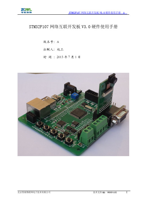
北京智嵌物联网电子技术有限公司技术支持QQ:498034132ISTM32F107网络互联开发板V3.0硬件使用手册版本号:A拟制人:赵工时间:2013年7月1日目录1本文档编写目的 (1)2硬件接口说明 (1)3核心硬件电路说明 (2)3.1电源电路 (2)3.2按键与LED电路 (3)3.3JTAG下载电路 (4)3.4外扩存储电路 (5)3.5RS232通讯电路 (5)3.6RS485通讯电路 (6)3.7CAN通讯电路 (6)3.8USB电路 (6)3.9DS18B20电路 (7)3.10以太网接口电路 (7)3.112.4G无线接口 (8)4使用注意事项 (9)1本文档编写目的本使用手册是针对STM32F107网络互联开发板V2.2的硬件而编写的,包括硬件接口说明、核心硬件电路说明、使用注意事项等内容。
2硬件接口说明该开发板的硬件结构如图1所示:图1硬件结构框图开发板实物接口如图2所示:图2开发板硬件接口(注意:DS18B20的安装方向!有什么疑问及时与我们技术联系。
)DS18B20安装方式3核心硬件电路说明3.1电源电路开发板供电方式有两种:5V电源适配器供电和USB供电。
(1)5V适配器供电直接将5V适配器插在J6上即可为板子供电,电路如图3所示:图35V适配器供电接口电路(2)USB供电将MINI USB插在J10上,并将J2用跳线短接。
电路参考图11。
(3)5V转3.3V电路不论板子采用哪种供电方式,最终会将该5V电源转为3.3V为系统供电。
5V转3.3V电路如图4所示:图45V转3.3V电路由上图可以看出,D6为5V电源指示灯,R11为限流电阻,为增加灯的亮度可以取2.2K。
5V电源经过10uf电容C138滤波后进入SPX1117-3.3,该芯片是稳压芯片,输出3.3V,再经过10UF电容C3滤波后供后级电路使用。
3.2按键与LED电路开发板扩展了4个按键和4个LED指示灯。
红牛V3用户手册

, 、 、 , █ 1个5向摇杆 向摇杆, 1个 Reset 按钮 按钮、 1个 wakeup 按钮 按钮、 1个 Tamper 按键 按键, 1个自定义按钮 ,1个电源 LED ,1个 USB 通信指示 LED █ 4个自定义 LED LED, LED, 电池座 █ 1个 CR1220 CR1220电池座 █ 一路可调电位器输入模拟信号 (方便连接 ST-LINK ,JLINK , █ 标准 ARM JTAG 20 PIN 仿真接口座 仿真接口座( ST-LINK, JLINK, ULINK2 等主流仿真器 ) ULINK2等主流仿真器 等主流仿真器) █ 2个 BNC 输入端子,集成双通道示波器电路 █ 1个电源开关,上下电时无需拔插电缆 、系统存储器、 SRAM █ 3种启动方式:用户 Flash Flash、系统存储器、 、系统存储器、SRAM █ 所有 IO 口均引出,方便接外部电路做实验 █ 工业级四层板设计,抗干扰超强 : 160mm ×120mm █ PCB 尺寸 尺寸: 160mm×
电路及接口说明
由于空间有限标注未能一一说明每个接口和 IC 的定义和功能,需详细接口 定义资料请参考电路原理图。
1.1 Power supply(电源供给)
红牛开发板采用外部5V电源输入 ● 5V DC 电源适配器连接到power 。
2.2 Boot option(启动选项)
红牛开发板可以采用以下启动方式: ● Embedded user Flash (默认) ● System memory with boot loader for ISP ● Embedded SRAM for debugging
红牛开发板 V3 红牛开发板V3
用户手册
11 CopyRight@20 CopyRight@2011
紫光电子纸模块B用户手册说明书
2.9inch e-Paper Module (B)User ManualVersion Data DescriptionV1.0 2017.05.17 First EditionV2.0 2018.12.05 Notes【Notes】⚫Please read this manual before you use the e-Paper. Damage caused by wrong operations is not within the scope of the warranty⚫This manual shows you how to use the e-paper with the demo codes we provide. ⚫The e-paper described in this manual is Module/HAT version. (Raw panel should work with driver board)⚫All specification supplied herein are subject to change without notice at any time.Types Description (4)Notes (5)Overview (7)Specification (7)Interfaces (8)Working Principle (9)4-wire SPI (9)Demo codes (11)Download (11)Raspberry Pi (12)Hardware connection (12)Copy examples to Raspberry Pi (12)Libraries Installation (13)Running demo codes (15)Expected result (16)Arduino (17)Hardware connection (17)Running examples (17)Expected result (18)STM32 (19)Hardware connection (19)Running example (19)Expected result (19)Codes Description (20)Version (20)C codes (20)Python codes (24)Image Data Array (26)Generally, there are two versions for every type of e-paper, one is raw panel, and another is Module/HAT version.Raw panel should work with driver board, if you are the first time to use Waveshare e-Paper, we recommend you the Module/HAT version or purchase a driver board separately.Module/HAT version has PCB which integrates driver circuit. You can connect 8Pin connector to MCU directly.Raw Panel (2.9inch e-Paper B):Module Version (2.9inch e-Paper Module B):1.For those e-Paper which support partial refresh, you cannot use partial refresh allthe time. A full refresh should be done to clear screen after several times(partial refresh), otherwise, e-Paper will be damaged and cannot fixed.2.Three-color e-Paper is normal to be a little “color” . You can refresh it to whiteand keep it upward for storage.3.The e-Paper cannot be powered on for long time, you must set e-Paper to sleepmode or power off when it needn’t refresh, otherwise, e-Paper keeps in high voltage status for long time, which will damage e-Paper and cannot be fixed.4.We suggest you update e-Paper once every 24 hours or at least 10 days1toupdate again. Otherwise, ghost of the last content may cannot be cleared.5.e-Paper ignores the data sent when it is in sleep mode, you need to initialize it forproperly refreshing.6.You can adjust border color by controlling 0x3C register. In some of demo codes,you can adjust Border Waveform Control or VCOM AND DATA INERTVAL SETTING registers.7.If you find that the image data you made cannot be properly displayed on e-Paper, please check the size of image, or change its width and height and tryagain.1For details of operating requirement, please refer to datasheet8.The e-Paper cannot refresh directly under sunlight2. The refresh steps should bedone indoor9.For raw panel, its working voltage is 3.3V, note that when you designed you owndriver board, level convert circuit is required if the working voltage of your board is 5V. Module/HAT version can support 5V voltage if the Module you buy is the new version which has been integrated convert circuit.10.The FPC of the panel is fragile, please make sure that your bend it in correct way.11.The glass raw panel is fragile, please do not falling, crashing or pressing hard.12.We recommend you test the e-Paper with our demo code when you first timereceive it.2e-Paper don’t have UV film, cannot work under sunlight directly⚫This is an E-Ink display module, 2.9inch, 296x128 resolution, with embedded controller, communicating via SPI interface, support Red, black and white three color.⚫Due to the advantages like ultra-low power consumption, wide viewing angle, clear display without electricity, it is an ideal choice for applications such as shelf label, industrial instrument, and so on.⚫We provide demo codes for you (Arduino, Raspberry Pi and STM32) SPECIFICATION⚫Operating Voltage: 3.3V/5V3⚫Wo rking Temperature: 0~50°C⚫Interface: 3-wire SPI/4-wire SPI⚫Dimension:◼PCB: 89.5mm × 38mm◼Raw Panel: 79.0mm × 36.7mm⚫Display area: 66.89mm × 29.05mm⚫Dot pitch: 0.138 × 0.138⚫Resolution: 296 × 128⚫Display color: Red, Black, White⚫Refresh time4:3The voltage of every pins should be same 3.3V or 5V4These are experimental data; actual data may be different according to working situation◼Full refresh: 15s⚫Consumption5:◼Refresh consumption: 26.4mW(typ.)◼Standby consumption: <0.017mW⚫V iewing angle: >170°INTERFACESVCC :3.3V/5VGND :GNDDIN :SPI MOSI pinCLK :SPI SCK pinCS :SPI chip selection, low activeDC :Data/Command Selection(High: Data; Low: Command)RST :Reset(Low active)BUSY :Busy(Low active)5These are experimental data; actual data may be different according to working situationThis product is an E-paper device adopting the image display technology of Microencapsulated Electrophoretic Display, MED. The initial approach is to create tiny spheres, in which the charged color pigments are suspending in the transparent oil and would move depending on the electronic charge. The E-paper screen display patterns by reflecting the ambient light, so it has no background light requirement. Under sunshine, the E-paper screen still has high visibility with a wide viewing angle of 180 degree. It is the ideal choice for E-reading.4-WIRE SPIDifferent from the traditional SPI protocol6, the data line from the slave to the master is hidden since the device only has display requirement.⚫CS is slave chip select, when CS is low, the chip is enabled.6You can search online for more information about traditional SPI protocol⚫DC is data/command control pin, when DC = 0, write command, when DC = 1, write data.⚫SCLK is the SPI communication clock.⚫SDIN is the data line from the master to the slave in SPI communication.SPI communication has data transfer timing, which is combined by CPHA and CPOL. 1.CPOL determines the level of the serial synchronous clock at idle state. WhenCPOL = 0, the level is Low. However, CPOL has little effect to the transmission. 2.CPHA determines whether data is collected at the first clock edge or at the secondclock edge of serial synchronous clock; when CPHL = 0, data is collected at the first clock edge.⚫There are 4 SPI communication modes. SPI0 is commonly used, in which CPHL = 0, CPOL = 0.As you can see from the figure above, data transmission starts at the first falling edge of SCLK, and 8 bits of data are transferred in one clock cycle. In here, SPI0 is in used, and data is transferred by bits, MSB.DOWNLOADPlease visit Waveshare Wiki, search with key words “2.9inch e-Paper module. Download the demo code from wiki,Extract it and you can get these folders:Arduino7: Demo code for Arduino UNO;RaspberryPi: Demo codes for Raspberry Pi. (BCM2835, wiringPi and python) STM32: Demo code for STM32, control board is STM32F103ZET67If you use other Arduino board, you should check if it is compatible with Arduino Uno, or modification is required.RASPBERRY PIThere are four examples for Raspberry Pi, bcm2835, wiringPi, python2 and python3. HARDWARE CONNECTIONCOPY EXAMPLES TO RASPBERRY PI1.Insert SD card which has Raspbian installed to your PC2.Copy RaspberryPi extracted to root directory (BOOT) of SD card3.Power on your Raspberry Pi and open Terminal, you can find that the examples arelisted in boot directory4.Copy the RaspberryPi folder to /home/pi and change its execute permission.LIBRARIES INSTALLATIONTo use demo codes, libraries should be installed first.BCM2835 LIBRARYDownload link of the bcm2835 library: /mikem/bcm2835/ Download the library and copy it to raspberry pi without extracting. Open terminal of raspberry pi and install:Note: xx is version of the library you download. For example, if the version is bcm2835-1.52, you should complete the command to: sudo tar zxvf bcm2835-1.52.tar.gzWIRINGPI LIBRARYOpen Terminal and install wiringPi with commands below:PYTHON2 LIBRARYOpen Terminal and execute commands to install:PYTHON3 LIBRARYOpen Terminal and install library with commands:If you get the error while installing Pillow: ImportError: libopenjp2.so.7: cannot open shared object file: No such file or directory. Please install libopenjp2-7-dev with the command: sudo apt-get install libopenjp2-7-dev then try again.RUNNING DEMO CODESEnter folder of examplesRunning bcm2835 example:Running wiringPi example:Running python2 example:Running python3 example:EXPECTED RESULTAfter running example:1)The screen is refresh to white2)Display a picture3)Draw circles and lines, text is displayedYou can press ctrl and c at the same time to stop code.ARDUINONote: If the driver board you bought is e-Paper shield, you can use the demo codes provided for e-Paper shield separately which can be downloaded in corresponding wiki.HARDWARE CONNECTIONIf you use other Arduino board instead of Arduino UNO, you should check if its interfaces are compatible with UNO.RUNNING EXAMPLES1.Make sure you have installed Arduino IDE in your PC2.Open Arduino project3.Select correct Board and Portpile and upload to Arduino boardEXPECTED RESULTUNO PLUS has only 2k flash for global variables, cannot support a full image buffer. Therefore only picture display function is provided for Arduino example。
FPGA开发板 使用说明书

目录第一章 综述 (1)其次章 系统模块 (1)第三章 软件的介绍 (10)第四章 USB 电缆的安装与运用 (27)第一章 综述THSOPC-3型FPGA开发板是依据现代电子发展的方向,集EDA和SOPC系统开发为一体的综合性试验开发板,除了满意高校专、本科生和探讨生的SOPC教学试验开发之外,也是电子设计和电子项目开发的志向工具。
一、好用范围:●自主创新应用开发;●单片机与FPGA联合开发;●IC设计硬件仿真;●科研项目硬件验证与开发;●高速高档自主学问产权电子产品开发;●毕业设计平台;●探讨生课题开发;●电子设计竞赛培训;●现代DSP开发应用;●针对各类CPU IP核的片上系统开发;●DSP Biulder系统设计。
二、硬件配置:THSOPC-3型FPGA开发板基于Altera Cyclone II 器件的嵌入式系统开发供应了一个很好的硬件平台,它可以为开发人员供应以下资源:●支持+5V 电源适配器干脆输入或者USB接口供电,5V、3.3V、1.2V混合电压源;●FPGACycloneII FPGA EP2C8,40万门,2个锁相环;●isp单片机AT89S8253。
isp单片机AT89S8253及开发编程工具,MCS51兼容,12KB isp可编程Flash ROM,2KB ispEEPROM,都是10万次烧写周期;2.7-5.5V工作电压;0-24MHz工作时钟;可编程看门狗;增加型SPI串口,9个中断源等。
此单片机可与FPGA联合开发,特别符合实现当今电子设计竞赛项目的功能与指标实现;●EPM3032 CPLD;● 4 Mbits 的EPCS4 配置芯片;●512KB高速SRAM;●20MHz 高精度时钟源(可倍频到300MHz);● 4 个用户自定义按键;●8 个用户自定义开关;●8 个用户自定义LED;● 2 个七段码LED;●标准AS 编程接口和JTAG调试接口;●两个标准2.54mm扩展接口,供用户自由扩展;●RS-232 DB9串行接口;●PS/2键盘接口;●VGA 接口;●4X4键盘;●液晶显示屏20字X4行;●USB-Blaster 编程器,可对FPGA 通过JTAG 口编程、调试、测试;单片机编程ByterBlasreMV 编程器;●光盘:配套子程序库、资料、编程软件、试验指导书。
- 1、下载文档前请自行甄别文档内容的完整性,平台不提供额外的编辑、内容补充、找答案等附加服务。
- 2、"仅部分预览"的文档,不可在线预览部分如存在完整性等问题,可反馈申请退款(可完整预览的文档不适用该条件!)。
- 3、如文档侵犯您的权益,请联系客服反馈,我们会尽快为您处理(人工客服工作时间:9:00-18:30)。
MSP430F149 开发板使用说明2011年01月第一章新手入门1.1 MSP430F149 学习板特点:选用16 位超低功耗单片机MSP430F149,采用子母双板分离设计,MCU 子板与集成外设母板通过插针座连接,使用灵活方便。
Ø一个 RTC实时时钟+纽扣电池Ø一个继电器输出Ø一个红外接收器Ø一个EEPROM (AT24C08)Ø一个单路输出 8-Bit数模转换器(DAC)Ø一个 4×4的矩阵式键盘Ø一个 4×1的独立式按键(与4×4的矩阵式键盘复用)Ø一个标准的 RS232接口Ø一个标准的RS485接口Ø一个含8个LED的流水灯电路ØMCU 的全部IO都用插针引出,便于二次开发基本单元测试程序包括以下几个部分:一、基础实验1、入门试验:LED 闪烁2、时钟实验:设置MCLK、ACLK、SMCLK3、低功耗实验:设置低功耗模式4、IO 端口试验:IO 端口寄存器设置5、定时器:看门狗定时器、TimerA 寄存器设置6、比较器:比较器A 寄存器7、Flash:flash 读写8、异步通信:异步通信寄存器设置9、ADC:ADC12 寄存器设置二、开发板模块程序【44个】1、LED 流水灯实验(1)LED1:检测开发板(2)LED2:普通IO 控制闪烁(3)LED3:PWM 信号控制闪烁2、蜂鸣器实验(1)蜂鸣器1:单频音(步进变音调)(2)蜂鸣器2:奏乐(祝你平安)3、数码管实验(1)数码管1(显示12345678)(2)数码管2(动态显示0~F)(3)数码管3(流动光圈)(4)数码管4(来回光标)4、4×1 独立按键实验(1)4×1 键盘1:扫描数码管显示(2)4×1 键盘4:控制蜂鸣器5、4×4 矩阵键盘实验(1)4×4 键盘1:行列扫描数码管显示(2)4×4 键盘2:行列扫描1602 液晶显示6、1602 液晶实验(1)1602 液晶1:动态字符显示(2)1602 液晶2:静态字符显示(3)1602 液晶3:内部时钟显示7、3.3V-5V 电平转换实验(1)电平转换1:输出5V 方波8、RS232 接口实验(1)RS232 接口1:MCU 发送数据PC 机显示(2)RS232 接口2:按键控制MCU 发送数据PC 机显示(3)RS232 接口3:PC 机发送数据MCU 液晶显示(4)RS232 接口4:MCU 回发接收到的PC 机数据9、RS485 接口实验(1)RS485 接口1:发送程序10、PS2 接口实验(1)PS2 接口1:PS2 控制1602 显示11、12-Bit 高精度温度传感器实验(1)温度传感器1:DS18B20 在数码管显示(2)温度传感器2:DS18B20 在液晶显示12、RTC 实时时钟实验(1)实时时钟1:DS1302 测试(2)实时时钟2:DS1302 电子钟13、2k Bit EEPROM 实验(1)EEPROM1:AT24C02 测试(2)EEPROM2:读出数据通过串口在PC 机显示14、12-Bit 模数转换器(ADC)接口实验(1)模数转换器2:ADC 在1602 液晶在显示(2)模数转换器3:ADC 通过串口在PC 机显示15、8-Bit 数模转换器(DAC)实验(1)数模转换器1:DAC 控制LED(2)数模转换器2:DAC 输出电压,ADC 采样转换并在液晶上显示16、12864 液晶实验(与12864 液晶配套)(1)12864 液晶并口1:字符显示(2)12864 液晶并口2:汉字显示(3)12864 液晶并口3:图形显示(4)12864 液晶并口4:综合演示(5)12864 液晶串口5:字符显示(6)12864 液晶串口6:汉字显示(7)12864 液晶串口7:图形显示(8)12864 液晶串口8:综合演示17、继电器实验(1)接口控制继电器,继电器动作,指示灯闪烁18、HS0038红外接口实验(1)红外遥控解码实验,在数码管上显示三、开发板综合程序【5 个】1、键盘综合实验(1)4×4 键盘+蜂鸣器+LED+PC 机显示(2)PS2 键盘+UART+PC 机显示2、温度时间综合实验(1)DS18B20 + DS1302 + 16023、DA综合实验(1)DAC + UART4、SSCOM综合实验(1)PC发送接收字符第三章板上资源详解本章详细介绍了MSP430F149 学习板上各个功能模块的硬件电路原理、使用方法和注意事项,使用前请仔细阅读。
在本章的介绍中并没有具体给出每个芯片的操作方法和读写时序图,请阅读每个小节最后的“推荐阅读”中指定的PDF 文档来获得有关器件的详细使用信息。
首先介绍控制开发板大部分功能的7位拨码开关,从左到右依次为1→7分别是:JDQ(继电器)、SN74LVC(3.3V→5V电平转换)、LCD(液晶)、SMG(数码管)、KEY(键盘)、BUZZER(蜂鸣器)、LED(流水灯)。
拨码开关控制着这几部分模块的供电,如果将拨码开关相应的位拨至OFF上,则该部分功能电路将断电3.1 RS232 接口电路MAX3232 是一款3.0V~5.5V 供电、低功率的RS232 收发器,支持高达1Mbps 的通信速率,仅需要五个0.1uF 的电容作为外部元件即能工作。
MCU 与MAX3232 连接关系示意图如图3.1 所示。
图 3.1 MCU 与MAX3232 的连接图MSP430F149 片内集成了两个UART 端口,这里使用了它的UART0 端口,MCU 通过UTXD0(P3.4)向PC 机发送数据,通过URXD0(P3.5)接收来自PC 机的数据。
在TX 线和RX 线上分别有一个红色LED,当MCU 通过MAX3232 与PC 机通信时,两个LED 会根据通信线上电平的变化而闪烁,指示通信的进行。
如果不用作UART 通信,则当P3.4 和P3.5 用于通用输入输出端口时,P3.4 和P3.5 连接的标号为D9 和D10 的两个LED 可以作为通用LED 使用。
推荐阅读:MAX3232.pdf3.2 RS485 接口电路MAX3485 内部集成了一个三态的平衡驱动器和一个差分接收器,专为基于总线传输的多点数据通信而设计。
它的制造标准完全符合ANSI TIA/EIA-485-A 规范的要求,MAX3485 的驱动器输出能力最大达±60mA,具有过热保护电路,同时具有正负电流限制;接收器的最小输入阻抗为12KΩ,接收灵敏度±200mV,是一款性能优良的工作在半双工模式的RS485 收发器。
MCU 与MAX3485 的连接关系示意图如图 3.2 所示。
图 3.2 MCU 与MAX3485 的连接图在上图中,将MAX3485 的RE引脚与DE 引脚连接在一起,通过MCU的P3.3 端口可以直接控制收发模式。
当P3.3 输出高电平时,MAX3485 处于发送数据模式;当P3.3 输出低电平时,MAX3485 处于接收数据模式。
这里使用MSP430F149 内部的UART1 端口来实现RS485 串行通信,MCU 通过UTXD1(P3.6)向RS485 总线发送数据,通过URXD1(P3.7)接收来自RS485 总线的数据。
注意:MCU 在发送数据前必须先设置P3.3 端口输出高电平,让MAX3485 处于发送数据模式,然后才能通过UTXD1(P3.6)向总线发送数据;同理,MCU 在接收数据前必须先设置P3.3 端口输出低电平,让MAX3485 处于接收数据模式,然后才能通过URXD1(P3.7)接收总线上的数据。
推荐阅读:MAX3485.pdf3.3 EEPROM 电路AT24C08 是Atmel公司出品的一款高性能EEPROM芯片,它采用两线串行接口(I2C)简化了与MCU的连接,工作电压 2.7V~5.5V,存储容量 8K字节,支持 100 万次的擦写,数据能有效保持 100 年。
MCU与AT24C08 的连接关系示意图如图 3.3 所示。
图 3.3 MCU 与AT24C02 的连接图MCU的通用输入输出(GPIO)端口P1.2、P1.3 与AT24C08 的SCL、SDA端口相连接构成I2C总线,因为MSP430F149 内部没有专用的I2C接口电路,所以只能用IO端口来模拟I2C时序从而实现对EEPROM的读写操作。
从图 3.3 中我们可以看到EEPROM地址选择端口A0~A2 都外接低电平,所以进行I2C通信时,EEPROM的从机地址是唯一的,即A0~A2 所对应的地址控制位均为 0。
因为AT24C0X(X=1,2,4,8,16)系列芯片的管脚是兼容的,所以用户也可以自行更换其他型号的芯片,无需改动任何硬件结构,只需注意器件地址和存储空间寻址模式的变化,相应地修改软件程序即可。
使用此模块电路时无需设置跳线,直接应用即可。
推荐阅读:AT24C0X.pdf3.4 实时时钟电路DS1302 能够计算秒、分、时、日、周、月、年,自动补偿 2100 年之前的闰年日期;2.0V~5.5V 的供电电压,三线制的串行通信接口,且内置 31 字节的可由电池维持数据的静态 RAM,用户可自由使用。
DS1302 的最大特色是支持双电源供电,VCC2 连接主电源,VCC1 连接备用电池。
当 VCC2 的电压高于 VCC1 时,芯片从 VCC2 处获得能量并且可以通过涓流充电的方式对VCC1 连接的电池进行充电;当 VCC2 的电源断开连接时,芯片内部自动切换到从 VCC1 处取电,从而保证即使在系统板掉电的情况下,DS1302 仍能进行正确计时功能且保存在 RAM 中的数据不丢失。
MCU 与 DS1302 的连接示意图如图 3.4 所示。
图 3.4 MCU 与DS1302 的连接图MCU 通过其GPIO 的P2.5、P2.6、P2.7 端口与DS1302 的SCLK、I/O、RST 三个引脚连接,通过这个三个IO 就可以执行对DS1302 的全部操作了。
DS1302 的第 1 管脚接到了系统板的 3.3V 电源上,作为芯片的主电源;第8 管脚连接了一个CR2032 型纽扣电池的正极,为芯片提供系统板掉电后的能量。
推荐阅读:DS1302.pdf3.5 DAC 电路DAC5571 是一款低功耗、单通道、8-Bit分辨率的缓冲型电压输出数模转换器。
上电复位以后,它固定输出 0V电压;2.7V~5.5V的宽供电电压,通过I2C 接口与MCU连接、支持高达 3.4Mbps的通信速率,输出快速更新速率188KSPS。
