Xilinx CORDIC算法(非常经典)
Cordic算法说明与实现设计(word文档良心出品)

Cordic 算法说明———— 王聪颖假设调制信号为()m t ,则其经FM 调制后的表达式为:0()cos(())tc f S t t K md ωττ=+⎰ 式(1)其中c ω为载波信号,f K 为常量。
因此,()m t 构成了()S t 信号的部分相位分量,而FM 解调过程就是将()m t 从()S t 的相位中提取出来,这里就可以通过Cordic 算法计算出()S t 信号的相位。
一、算法介绍在本次设计中,为了实现FM 的解调,主要对比了三种算法的实现方法:查表法和Cordic 算法的两种不同实现方法。
下面一一进行介绍:1)查表法:此方法其依据是当[0,/4]θπ∈时,tan [0,1]θ∈且单调递增,这样就可以在[0,/4]θπ∈内建立一个tan θ与θ相对应的表,根据tan θ计算出当前的相位值,同时,利用三角函数关系,将[0,2]π分成大小为/4π的8个部分,并将它们映射至[0,/4]π内从而准确求解。
2)Cordic 算法:其核心是笛卡尔坐标平面旋转,即在xy 坐标平面上将点11(,)x y 旋转θ角度到点22(,)x y 的标准方法如下所示:211211cos sin sin cos x x y y x y θθθθ=-⎫⎬=+⎭式(2)图1 平面坐标旋转示意图将式(2)中的cos θ提取出来,在增加一角度累加方程,即可得到Cordic 算法方程组。
(1)()()(1)()()(1)()()tan tan i i i j i i i j i i i j x x d y y y d y z z d θθθ+++⎫=-⎪=+⎬⎪=-⎭式(3) 在式(3)中,j d 的值为1或-1。
在这里出现两种方法实现Cordic 算法以求的相位:1)取02*45i θ-=,2)取t a n 2iθ-=。
第一种方式暂且称为Cordic 角度法,第二种方式我们暂且称之为Cordic 正切法。
二、算法的比较及实现三种通过计算相位来进行FM解调的算法有其不同的特点:查表法:其思路简单,只需要利用输入的正弦和余弦值求得其映射在0~45度间的正切值,然后进行查表最终获得相位值。
CORDIC算法原理及实现

图4.1 圆坐标系旋转
CORDIC算法原理 --圆坐标系旋转原理
上面的方程组同样可写成矩阵向量形式:
x2 cos y sin 2 sin x1 y cos 1
例如一个90o相移为:
x2 0 1 x1 - y1 y 1 0 y x 1 1 2
x (i 1) x (i ) y (i ) di 2 i y (i 1) y (i ) x (i ) d i 2 i z (i 1) z (i ) d i e (i )
1
z
(0)
通过设定x(0)=1和z(0)=0来计算tan-1y(0)。向量模式 中,判决算子di 满足下面条件:
d i sign ( x (i ) y (i ) )
因此 我们输入x(0)和y(0)(z(0)=0),并通过迭代使y(0) 取值趋近于0。
CORDIC算法原理 --向量模式
CORDIC算法原理 --圆坐标系旋转原理
前面所示的伪旋转现在可以表示为(对每次迭代):
x (i 1) x (i ) d i (2 i y (i ) )
(4.7) 在这里引入第三个方程,被称为角度累加器,用来在 每次迭代过程中追踪累加的旋转角度: z (i 1) z (i ) d i (i ) (4.8) 这里:di=±1。符号di是一个判决算子,用于确定旋转的方向。 上述三个方程式为圆周坐标系中用于角度旋转的CORDIC算法的 表达式。在本章的后续部分中我们还将看到CORDIC算法被用于其 它的坐标系,通过使用这些坐标系可以执行更大范围的函数计算。
CORDIC算法原理 --圆坐标系旋转原理
CORDIC算法在FPGA中的实现
微 处 理 机M I CROPROCESS ORS・大规模集成电路设计、制造与应用・C ORD I C 算法在FPG A 中的实现王智霞,王广生(北京工业大学电控学院,北京100022) 摘 要:CORD I C 算法是在许多角度计算方面有着广泛应用的经典算法,通过考虑FPG A 的结构、精度局限和速度要求,采用流水线技术(p i peline ),在FPG A 上用CORD I C 算法实现了对于大吞吐量数据的向量倾角的计算,并对实际应用中内部步骤寄存器精度的选取给出了较为详细的方法。
关键词:坐标旋转数字计算;FPG A;流水线中图分类号:T N4 文献标识码:B 文章编号:1002-2279(2007)01-0004-04FP GA B a sed R ea li za ti o n o f CO RD I C A l go rithmWANG Zhi -xia,WANG Guang -sheng(B eijing university of technology,B eijing 100022,China ) Abstract:CORD I C algorithm is a classic algorith m with many app licati ons .Considering the archi 2tecture,p recisi on and s peed of FPG A ,the p i peline technol ogy is used in computing large number of vect or angle values .This article p r ovides the way of confir m the wide of inner p r ocessing register .Key words:CORD I C;FPG A;Pi peline1 引 言FPG A 以其灵活性和使用方便在现今的数字领域已经得到了广泛的应用。
CORDIC算法
Tools
• Aldec Active-HDL, Synplify Pro, Xilinx ISE (Windows Platform) • Cadence – Verilog-XL & Simvision • Synopsys Design Analyzer (Unix Platform)
Why CORDIC ?
How to evaluate trigonometric functions?
• • • Table lookup Polynomial approximations CORDIC
Compared to other approaches, CORDIC is a clear winner when :
FPGA(3s200ft256) Results
Sequential Parallel Pipeline LUT Gate Count Path Delay 597 5833 9.7 864 10371 867 14536 9.7
ASIC (TSMC) Results
Sequential Parallel Pipeline Parallel – SD Adder 9138 39019 62937 356015 22.9m 3mW W 28.3 9.7 27.4m W 7.82
Example
r = 10 , digit set [0,9] 5 7 8 2 4 + 6 2 9 3 8 11 9 17 5 12 11 9 16 5 12 0 0 1 0 0 2 11 10 16 5 14 9 9 18 16 16
[0,18] [0,16] [0,2] [0,16]
cordic算法及其FPGA硬件实现 毕业论文

第一
1.1 CORDIC
1.1.1 CORDIC
CORDIC(Coordinate Rotational Digital Computer-坐标旋转数字计算机)算法最早由J.Volder等人于1959年在美国航空控制系统的设计中提出,他的基本思想是:通过坐标轴旋转得出一个二维的函数关系式,对初始角度进行数值线性逼近,把初始角度的旋转转化成一系列基本角度逐次旋转完成,然后运用递推原理,得出一组递推公式,把每次递推得到的角度加进去,转换成一组三维的函数关系式,进一步推导,最终用圆周模型、线性模型、双曲线模型实现了加减乘除、三角函数、双曲线三角函数、平方根,指数、对数等函数的运算。20年后,随着VLSI的产生和迅速发展,CORDIC算法开始被重视,并得到了广泛的应用。原始算法描述的是二维的旋转,它被应用于数字信号处理(如:傅里叶变换、数字滤波器)、计算机图像处理和机器人技术等领域。
由于CORDIC算法本身具有众多的优点,目前,已经应用于很多领域,例如:8087数学协处理器、HP-35计算器、天气预报、雷达信号处理、三维图像处理、嵌入式系统以及移动通信、数控振荡器、数字下变频器及数字鉴别器等;此外,它还应用于许多数字信号处理问题,如:快速傅里叶变换、离散余弦变换、小波变换、数字滤波器、离散Hartley以及求解线性系统。Altera公司和Xilinx公司13还推出了CORDIC算法实现的IP核,可以按照实际需求直接调用。
在数字信号处理中,高速高精度的三角函数发生器有着广泛的应用,在通常情况下,计算三角函数、反三角函数、双曲线函数和其它超越函数有效的方法有:ROM查找表法、多项式近似法(主要是利用泰勒级数近似)、CORDIC法。
改进型高速高精度CORDIC算法及其在DDFS中的应用

改进型高速高精度CORDIC算法及其在DDFS中的应用史方显;曾立;陈昱;王淼;占丰【摘要】提出了一种新的选择迭代式高速高精度CORDIC(COrdinate Rotation Digital Computer)算法.基于表驱动法缩小目标旋转角度,通过改进的基本角度选择方法旁路不必要的迭代;并以移位和减法实现幅度校正,减小硬件资源消耗.设定角度误差小于10-5rad时,迭代次数减小至7次以下.在DDFS(Direct Digital Frequency Synthesizer)的应用中,利用区间压缩技术在Xilinx的FPGA中实现20位定点小数电路设计.仿真及实测结果表明,该算法幅度误差小于2×10⁻⁵,输出延时不大于43.5ns,同时硬件资源消耗不增加.%A novel optional-iteration high speed and high precision CORDIC algorithm is proposed in this paper.First the rotation is conducted with a corresponding angle based on table-driven method.Then the algorithm bypasses unnecessary iterations using a new basic angle choosing technique.And the correction is achieved by shift and subtraction to reduce hardware consumption.Calculation and simulation indicate that the new algorithm can reduce the iteration number to less than 7 when the phase error is smaller than 10-5 rad.In the application of DDFS,20 fractional binary bits design is implemented in Xilinx FPGA with range reduction method.This design can reduce amplitude error to smaller than 2 x 10⁻⁵ for sine and cosine,cut the output delay down to 43.5ns in circuit test,and no hardware consumption increase.【期刊名称】《电子学报》【年(卷),期】2017(045)002【总页数】6页(P446-451)【关键词】坐标旋转数字计算机;直接数字频率合成器;表驱动;现场可编程门阵列【作者】史方显;曾立;陈昱;王淼;占丰【作者单位】北京航空航天大学宇航学院,北京100191;北京航空航天大学宇航学院,北京100191;北京航空航天大学宇航学院,北京100191;北京航空航天大学宇航学院,北京100191;山东航天电子技术研究所,山东烟台264000【正文语种】中文【中图分类】TN431.2直接数字频率合成技术(DDFS)属于第三代频率合成技术,由Tierney J在1971年首先提出[1].传统的DDFS基于查找表(LUT)技术,其主要结构包括相位累加器、查找表、DAC和低通滤波器.累加器在时钟的上升沿对频率控制字进行累加,将结果作为地址在查找表中读出正余弦值,通过DAC后进行低通滤波.在满足Nyquist采样定律的情况下,增大频率控制字可增大合成的频率.这种方法具有快速转换、高频率分辨率、低相位噪声和相位连续等优点[2].但由于有限字长的截断误差,基于查找表的DDFS必须在精度和面积、速度之间折衷.坐标旋转数字计算机(CORDIC)可通过移位和加减计算平方根、正余弦、模长与相位以及坐标变换,易于在FPGA等VLSI 器件中实现,广泛应用于FFT、矩阵分解和DDFS[3].CORDIC算法最早由Volder J E在1959年提出[4],圆周坐标下的CORDIC算法的核心思想是通过一系列的基本角度{θi=arctan2-i}的加减逐渐逼近输入角度,并对结果进行校正,i依次递增.其基本公式为其中x、y为旋转向量端点的横坐标值和纵坐标值.由式(1)可知旋转的过程中剩余未旋转角度zi的绝对值不断趋近于0,δi∈{-1,1}用以指示zi的正负,当δi=-1时逆时针旋转,δi=1时顺时针旋转.设旋转前后的向量长度分别为Ri和Ri+1,则有[4]即每次旋转后向量长度增加,为确保其端点仍在单位圆上,应对式(1)计算结果进行校正,且第i次旋转的校正系数为提高运算速度的主要方法有减小迭代次数、降低关键路径延时等,如文献[5]提出了改进型的并行CORDIC,但其精度只能达到10-4量级.文献[6]在资源利用率上有一定优势,但迭代过程依赖于时钟信号,导致延时较长.传统的CORDIC算法中的i是单调递增的,在|zi|较小的情况下仍可能进行较大角度旋转,致使迭代次数较大.文献[7]等提出了可调整基本角度系数的基4混合CORDIC,但判断系数所用的选择方程比较复杂,硬件资源消耗较大.针对传统算法的这些缺点,本文提出一种新的选择迭代式CORDIC算法,以相对简单的方式跳过不必要的旋转,在减小迭代次数的同时确保硬件资源消耗不增加.3.1 算法说明将[0,π/4]等分为长度为I的区间,第m个区间起点为αm,正余弦值{sinαm}和{cosαm}以及基本角度{θi}均存储在查找表中,其中0≤m≤⎣π/4I」且m为正整数,tanθi=2-i.输入角度φ首先通过由{αm}组成的比较阵列,根据比较结果返回m 的值,查表得x0=cosαm、y0=sinαm做为旋转的起点,此时已经旋转至φ的附近,故实际旋转的目标角度为φ-αm,且满足φ-αm≤φ.后续迭代均采用与zi绝对值最相近的基本角度θi,此时|θi-|zi||取最小值.i在增大的过程中跳过某些值,以此加速|zi|→0的过程,将迭代次数减小至最低.当i→∞时zi→0,此时的xi和yi为cosφ和sinφ的精确值,但实际的迭代次数是有限的,假设迭代次数为N.浮点数格式下忽略舍入误差,CORDIC的精度是由角度误差Δφ确定的.取相同的角度误差Δφ引起的正弦逼近误差为正弦的2阶导数为-sinx,∀x∈(0,π/4]其2阶导数小于0,Φyerr(φ)单调递减,由此可得最大误差出现在Φyerr(0)=sin(Δφ),同理可得∀x∈(0,π/4]余弦函数的最大逼近误差为Φxerr(π/4)= cos(π/4)-cos(π/4+Δφ).设精度要求为误差上限不大于f,且sin(Δφ)> cos(π/4)-cos(π/4+Δφ),由此可确定迭代终止的条件为max(θi)取不大于φ-αm的最大基本角度即可,同时取min(θi)≤Δφ以满足精度要求.3.2 求迭代次数上限由文献[8]可知,对于b位二进制小数下的CORDIC,当i ≥(b-log23)/3时,令θi=arctan2-i≈2-i不影响计算精度.由于实际旋转的目标角度较小,本文选取的i范围满足上述要求.若e满足则迭代次数的首次加1必定发生在[X+2-e,X+2-e+1]区间内,X为基本角度的线性组合.[0,2-e]范围内迭代次数为由0增大到1,[2-e,2-e+1]范围内迭代次数由1增加到2,[2-e+2+2-e,2-e+2+2-e+1]范围内迭代次数由2增大到3.根据规律提出以下假设:当N≥3时,迭代次数由N-1增大到N发生在以下区间上.以归纳法证明.当N=3时已证明成立,假设当N=s(s≥3)时仍成立,且区间A上的最大迭代次数为s.图1中则迭代次数由s-1增大到s发生在区间[L,M]中.由于4H、2H和H均为基本角度{θi≈2-i}中的元素,故角度2H、4H和角度H一样,可由一次旋转得到;且区间B、D长度与A相同,故除第一次旋转外,区间B、D上的剩余旋转与A相同,即区间B、D上的最大迭代次数为s.区间C、D上的迭代关于4H对称,所选基本角度相同,只是δi不同,因此区间C上的最大迭代次数仍为s. 最大迭代次数由s增大到s+1发生在区间[P,Q]上,此时相对于区间[L,M]多了一次旋转4H,且P、Q满足即N=s+1时假设仍成立,故对于N≥3假设均成立.在选定{θi}的情况下,最大迭代次数和区间长度正相关,当满足如下不等式时最大迭代次数为N-1.若将[0,π/4]等分为15个区间,此时αm+1-αm=π/60rad,精度要求在10-6数量级可得Δφ≈10-5rad,据此取5≤i≤18,根据式(6)得出e=15.由式(10)可得此时最大迭代次数为7,当φ-αm单调递增时,最早出现在区间内.3.3 MATLAB仿真验证在MATLAB中对本文提出改进型CORDIC算法和传统的CORDIC算法进行迭代,每隔10-6rad取一个点,可遍历{θi}在[0,π/4]内所有组合结果,并在角度误差不大于Δφ的情况下完成对[0,π/4]内任一角度的迭代.由图2可得本文提出的CORDIC算法迭代次数不超过7次,大部分集中在6次及以下,和式(10)得出的结果相同;传统的CORDIC算法最大迭代次数为16,且N大多集中在10次及以上.图2的下半部分给出了根据计算结果画出的余弦曲线和正弦误差,其幅值误差最大值为9.955×10-6.文献[7]提出的高基混合CORDIC算法达到n位精度需要的迭代次数为「3n/8+1⎣,误差为10-6量级时需要迭代大于9次,误差小于2×10-5时需要迭代大于8次;文献[6]的迭代分三级共24次.故本文提出的CORDIC算法在迭代次数上明显优于文献[6]和[7].MATLAB的计算是基于单精度浮点数,而在FPGA中进行浮点数的运算需要消耗大量的硬件资源;使用定点数会带来额外的舍入误差及其累积和传递,且定点数的乘法消耗的资源也较多.因此需要进行误差计算并重新考虑校正的方法.以下的分析均基于小数位宽为b的定点数.4.1 移位/减法进行校正校正因子{ki}是i的离散单调增函数,当i ≥5时满足0.999512076087079≤ki<1.设其二进制值为其中aj∈{0,1},传统的校正可表示为其中(xi)j表示xi右移j位的结果.由于满足条件的ki非常接近1,故aj=1的个数远大于aj=0的个数,进行乘法校正时部分积数目较大,耗费较多资源的同时也带来很大的延时[9];同理,若以移位/加法进行校正需要加法器的个数接近b.本文采用移位/减法的方式进行校正,取2-l≈1-ki,当满足1≤l<b时将待校正的xi右移l位得(xi)l,xi= xi- (xi)l为校正后的结果;yi同理.若l ≥b则(xi)l视为0,即ki≈1,可不进行校正,此时只需要1个减法器.由表1可知这种近似带来的误差很小.4.2 误差的计算式(12)表示校正后的第n+1次迭代,0≤n≤N-1.设本次迭代所选基本角度为θi,tanθi=2-i,此时校正因子为ki.算法最终计算结果的误差由3部分组成:(1)有限位宽带来的舍入误差Δx0、Δy0及其累积和传递的结果ΔxN、ΔyN;(2)以1-2-l近似ki带来的误差Δki;(3)迭代终止时Δφ带来的逼近误差.在矩阵模式下可表示为由多元函数的系统误差公式可得[10]其中Δxn为n次迭代舍入误差的累积值.同理可得根据文献[11]给出的公式,再考虑校正因子的误差可得舍入误差传递后的上限为其中其行列式的值满足且由式(14)~(18)得迭代最终误差如式(20)所示,将相应数值代入得其最大值不超过2×10-5.4.3 FPGA仿真与实测图3详细描述了本文提出的改进型CORDIC算法运算框图.在复位信号无效的情况下,累加器在时钟上升沿对频率控制字从-π开始进行累加,为保证相位的连续性,当累加结果溢出时将结果减去2π,累加器的输出送至区间压缩模块.将[-π,π]等分为8个区间,按照映射函数将[0,π/4]之外的角度压缩至[0,π/4][12].迭代完成后根据输入角度所在区间和三角函数的变换公式进行输出变换,结果输出到DAC.图4为Modelsim仿真所得输入角度(test-theta)、所在区间(interval)和正弦(sinvalue)余弦(cosvalue)波形,从图中可以看到相位的线性增加和溢出后减去2π再累加,interval信号的变化指示了输入角度所处区间,最后输出两路正交的正余弦信号.为完整表示[-π,π]内的角度,累加器进行运算时使用的是24位数据,包括1位符号位、3位整数位和20位小数位;压缩后的弧度制整数位为0,采用22位数据,包括1位符号位、1位整数位和20位小数位.将Modelsim仿真的数据导出,在Matlab中计算出20位定点小数下的误差如图5所示.由图5可得,误差的变化具有周期性,这是因为第二步旋转的起始角度φ-αm是周期变化的,最大误差均发生在迭代次数最多时,此时Δx0、Δy0累积和传递达到最大.由于Φyerr单调递减,Φxerr单调递增,故正弦的最大误差总体在减小,余弦的最大误差总体在增大,但两者的最大幅度均不超过2×10-5,符合计算结果.在[0,π/4]内φ相同时Δφ对余弦引起的误差总是小于正弦,故余弦函数的误差总体上小于正弦误差. 本设计电路的实现采用VHDL语言描述,FPGA型号为Xilinx公司Virtex5系列XC5VLX30,图6为实际输出波形.表2列出了本文设计与文献[5]和文献[6]的主要性能的对比,其中输出延时为FPGA实测数据.由于减小了迭代次数,本文提出的CORDIC算法精度最高,输出延时基本达到并行CORDIC算法的水平,运算速度比多级迭代的文献[6]有较大提高;且硬件资源消耗和文献[5]相比有所减少.本文提出的改进型CORDIC算法从以下两个方面减小迭代次数:(1)基于表驱动法一次旋转至输入角度附近,减小目标旋转角度的大小;(2)选取和剩余未旋转角度绝对值最相近的基本角度进行迭代,加速z→0的过程.迭代次数的减小降低了输出延迟,提高了速度;同时降低了舍入误差的传递和累积,提高了正余弦幅度精度.并通过移位/减法实现幅度校正,减少校正时加法器的使用数量,控制总的资源消耗.计算和实测结果表明,在硬件消耗未增加的情况下,本文提出的CORDIC算法在迭代次数、精度和速度等方面优于传统设计.史方显(通信作者) 男,1992年10月出生于安徽淮南.北京航空航天大学硕士研究生,研究方向为VHDL数字VLSI设计及FPGA在航天电子系统中的应用.E-mail:******************.cn曾立男,1976年8月出生于湖南邵阳.清华大学博士,北京航空航天大学副教授,研究方向为为空间环境仪器科学与工程.E-mail:**************.cn【相关文献】[1]Tierney J,Rader C M,Gold B.A digital frequency synthesizer[J].IEEE Transactions on Audio and Electroacoustics,1971,19(1):48-57.[2]Yang W,Hao M.A direct digital frequency synthesizer based on CORDIC algorithm implemented with FPGA[A].Proceedings of the 5th International Conference onASIC[C].Beijing,China:IEEE,2003.2:832-835.[3]Han W,Yousi Z,Xiaokang L.A parallel double-step CORDIC algorithm for digital down converter[A].2009 7th Annual Communication Networks and Services Research Conference (CNSR)[C].Moncton,BC,Canada:IEEE,2009.257-261.[4]Volder J E.The CORDIC trigonometric computing technique[J].IRE Transactions on Electronic Computers,1959,Ec-8(3):330-334.[5]祁艳杰,刘章发.基于Parallel-CORDIC的高精度高速度直接数字频率合成器的FPGA实现[J].电子学报,2014,42(7):1392-1397. QI Yan-jie,LIU Zhang-fa.FPGA implementation of high speed and high precision direct digital frequency synthesizer based on parallel-CORDIC[J].Acta Electronica Sinica,2014,42(7):1392-1397.(in Chinese)[6]Xin R,Zhang X,Li H,et al.An area optimized direct digital frequency synthesizer based on improved hybrid CORDIC algorithm[A].3rd International Workshop on Signal Design and Its Applications in Communications[C].Chengdu,China:IEEE,2007.243-246.[7]Shukla R,Ray K C.Low latency hybrid CORDIC algorithm[J].IEEE Transactions on Computers,2014,63(12):3066-3078.[8]Chuang T P,Huang C C,Hsiao S F.Design of a CORDIC-based SIN/COS intellectual property (IP) using predictable sign bits[A].Proceedings of the 27th European Solid-State Circuits Conference[C].Villach,Austria:IEEE,2001.277-280.[9]Han L,Ko S B.High-speed parallel decimal multiplication with redundant internal encodings[J].IEEE Transactions on Computers,2013,62(5):956-968.[10]Fei Yetai.Error Theory and Data Processing[M].Beijing:Higher Education Press,2010.66-74.(in Chinese)[11]Hu Y H.The quantization effects of the CORDIC algorithm[J].IEEE Transactions on Signal Processing,1992,40(4):834-844.[12]Maharatna K,Banerjee S,Grass E,et al.Modified virtually scaling-free adaptive CORDIC rotator algorithm and architecture[J].IEEE Transactions on Circuits and Systems for Video Technology,2005,15(11):1463-1474.。
CORDIC算法的优化及硬件实现

CORDIC算法的优化及硬件实现【摘要】本文介绍了CORDIC算法的基本原理并分析了其优化的方法,在QUARTUS9.0平台上基本实现了其功能,有效的降低了资源的消耗并提升了工作频率。
【关键词】CORDIC优化;FPGA;仿真CORDIC算法全称为坐标旋转数字计算机,它是由J.V older于1959年提出,cordic的运用大大降低了常用函数如sin,cos,sinh,cosh等在硬件上实现的难度,它主要是将复杂的函数在硬件上通过加减和移位运算递归计算出函数值,由于以上特性使得这一算法特变适合在FPGA上实现。
1.CORDIC算法基本原理CORDIC算法主要是在一个平面上某一向量(x1,y1)经过旋转角后得到新的向量(x2,y2),如图1所示。
根据变换规则二者有如下关系:2.传统CORDIC算法的局限性及优化CORDIC算法在FPGA中主要通过流水线来实现,通常要将提前算出作为的输入预先存储到ROM中,随着流水线级数的增加ROM表的容量成指数增长增加了系统的资源消耗,CORDIC每次运算都要经过多次迭代随着迭代次数的增加计算速度受到很大的影响,一个结果往往要经过多个时钟周期才能得到,此外传统的CORDIC算法的角度范围受到很大的约束,旋转的最大的角度范围为-99.88≤≤99.88无法达到0≤≤360必须对输入的角度预先进行处理才能使其达到收敛针对以上情况采取优化反正切函数表来减少迭代次数,简化校正因子等可以解决资源和速度的缺陷,对于角度的收敛问题采用分象限法如表1。
对于一个15级流水线可以通过以上的方法减少到12次迭代减少了3级流水线,并且减少了ROM的使用量提高了运行效率。
3.CORDIC算法硬件的实现由于CORDIC算法主要通过加减以及移位来实现,说以特别适合在FPGA 上实现,在这里我采用Altera公司的Cyclon2器件组中的EP2C5Q208C8整个实现过程都是在Quartus9.0中完成图2为系统的整体架构。
211018260_高精度低时延CORDIC算法
现代电子技术Modern Electronics Technique2023年4月1日第46卷第7期Apr.2023Vol.46No.70引言现代数字通信系统对傅里叶变换、三角函数、双曲函数等运算的高性能硬件实现结构的需求日益迫切[1⁃2]。
CORDIC (Coordinate Rotation Digital Computer )算法是一种规则化算法,它能够只通过移位与加减操作实现上述运算[3⁃4],其具有可移植性强、电路结构简单的特点,适用于现场可编程门阵列、专用集成电路等设计场合,因而受到众多科研单位的广泛研究,是当前重要的研究热点之一[5⁃6]。
随着数字集成化电路对CORDIC 算法的性能要求不断提高,国内外众多学者对其进行了相应的改进与优高精度低时延CORDIC 算法揭灿,朱晓宇,赵霁(中国电子科技集团第五十八研究所,江苏无锡214000)摘要:针对目前流水线型坐标旋转数字计算机(CORDIC )算法存在输出精度较低、输出时延较长的问题,提出一种基于移位相加结构的CORDIC 算法。
此算法首先对[0,π4)内的输入角度采用角度二极化重编码技术,将角度二进制编码转化为1和-1编码,然后使用移位相加结构替代查找表,同时通过合并迭代结构合并旋转迭代,减少迭代单元级数和迭代次数,降低硬件资源的消耗,建立小容量正余弦值ROM 表,降低接近于π2时部分输入角度的运算误差,最后结合角度区间映射手段保证算法运算范围覆盖整个圆周[0,2π)。
在Xilinx 公司KC705评估套件上进行算法验证与仿真,结果表明:在输出位宽都设定为16位的条件下,运算结果的绝对误差和相对误差相比流水线型CORDIC 算法分别降低了46.7%,83.5%,该算法只需6个时钟周期即可输出计算结果,输出时延减少了60.0%。
设计的CORDIC 算法具有输出精度高、输出时延短的优势,适用于实时、高精度的现代通信系统。
关键词:坐标旋转数字计算机;角度二极化重编码;移位相加;合并迭代;角度区间映射;数字信号处理中图分类号:TN492⁃34;TN914.3文献标识码:A文章编号:1004⁃373X (2023)07⁃0171⁃05CORDIC algorithm with high accuracy and low delayJIE Can ,ZHU Xiaoyu ,ZHAO Ji(The 58th Research Institute of China Electronics Technology Group Corporation ,Wuxi 214000,China )Abstract :A coordinate rotation digital computer (CORDIC )algorithm based on shift addition structure is proposed in this paper because the problems that the current pipelined CORDIC algorithm suffers low output accuracy and long output delay.The angle dipolarization recoding technology is used first in the new algorithm for the input angle in [0,π4)to convert the angle binary encoding into 1and -1encoding ,and then a shift⁃add structure is used instead of a lookup table ,while merging rotation iterations by merging iterative structures to reduce the number of iteration unit levels ,iterations and the consumption of hardware resources.Moreover ,a small ⁃capacity sine and cosine value ROM table is established in the proposed algorithm toreduce the calculation error of some input angles while it is close to π2.The angular interval mapping method is combined toensure that the calculation range of the algorithm covers the entire circumference [0,2π).Verification and simulation of thealgorithm were performed on the Xilinx KC705evaluation kit.The results show that when the output bit width is set to 16bits ,the absolute and relative errors of the operation results are reduced respectively by 46.7%and 83.5%compared with the pipelined CORDIC algorithm.The algorithm can output the calculation resultin only 6clock cycles ,and the output delay isreduced by 60.0%.The proposed CORDIC algorithm has the advantages of high output accuracy and short output delay.It is suitable for modernreal⁃time communication systems with high precision.Keywords :CORDIC ;angle bipolarization recoding ;shiftaddition ;merge iteration ;anglesection mapping ;digital signalprocessingDOI :10.16652/j.issn.1004⁃373x.2023.07.031引用格式:揭灿,朱晓宇,赵霁.高精度低时延CORDIC 算法[J].现代电子技术,2023,46(7):171⁃175.收稿日期:2022⁃08⁃19修回日期:2022⁃08⁃31171现代电子技术2023年第46卷化。
cordic算法原理与实现

CORDIC算法原理与实现引言概述在计算机科学和数学领域,CORDIC(Coordinate Rotation Digital Computer)算法是一种用于计算旋转和坐标转换的迭代算法。
由Jack E. Volder于1959年提出,CORDIC算法以其高效、简单的特性在数字信号处理、图形学和通信等领域得到了广泛应用。
本文将深入探讨CORDIC算法的原理和实现,揭示其在现代计算中的重要性。
正文内容1. CORDIC算法的基本原理1.1 旋转向量的基本概念CORDIC算法的核心思想是通过迭代旋转一个向量,使其逐步趋近于目标向量。
这里,向量旋转可以通过一系列坐标变换和旋转操作来完成。
在CORDIC中,旋转角度通常是一个固定的、预先设定的角度,如45度或30度。
1.2 坐标旋转的迭代过程CORDIC算法通过一系列迭代步骤,逐渐调整向量的坐标,使其最终趋近于目标向量。
每一步迭代都包括一个旋转和坐标调整操作,通过这种方式,算法能够在有限次迭代后收敛到所需的结果。
1.3 旋转因子的选择与优化CORDIC算法中,旋转因子的选择对算法的性能有着重要影响。
通过合理选择旋转因子,可以使得迭代过程更快速、更精确。
优化旋转因子的选择是CORDIC算法在不同应用中取得高性能的关键。
1.4 旋转模式与运算精度CORDIC算法支持不同的旋转模式,包括旋转、缩放和坐标转换等。
在应用中,需要根据具体问题选择合适的旋转模式。
此外,算法的运算精度也受到迭代次数的影响,需要权衡计算速度和精度。
1.5 硬件实现与软件实现CORDIC算法可以通过硬件电路实现,也可以通过软件编程实现。
硬件实现通常能够提供更高的运算速度,而软件实现更加灵活,适用于不同的计算平台。
选择合适的实现方式取决于具体应用的要求和硬件资源的可用性。
2. CORDIC算法的应用领域2.1 数字信号处理在数字信号处理领域,CORDIC算法常被用于计算旋转和相位调制等操作。
CORDIC算法数字瞬时测频的FPGA设计与实现

CORDIC算法数字瞬时测频的FPGA设计与实现摘要数字瞬时测频(DIFM)技术是现代电子战中的关键技术之一,要求在极短的时间内完成对输入信号频率的测量。
瞬时测频的基本思路是将频率信息转化为相位信息,再把相位信息转化为幅度信息,通过对幅度信息量化编码,从而完成对频率的测量。
本文提出了基于数字下变频、CORDIC算法相位测量以及相位推算法的数字瞬时测频方法以及在FPGA中的实现,对单频信号该方法具有测频精度高、瞬时性好的优点,特别适合现代电子战接收机数字瞬时测频的需求。
关键词数字下变频;CORDIC算法;数字瞬时测频;FPGA0 引言现代电子战环境下,雷达、通信信号非常密集,在同一个时间内会有多个信号出现,且频率覆盖范围广,为实现对这些同时信号的全概率覆盖,侦察接收机一般采用模拟和数字信道化技术,将一组固定通带滤波器输出的数字信号进行快速、宽频带、全概率的粗测频,然后再对各通道中被检测出的信号进行相对窄带、高精度的精测频[1]。
信号经过信道化处理后,如果子信道的带宽取得比较窄,则每个信道输出一个信号的概率比较大,此时可以采用一些时域测频算法进行测频,如相位推算法、瞬时自相关法、曲线拟合法和过零检测法等方法。
其中相位推算法具有运算量小、速度快、精度高、利用很少采样点就可以实现频率的估计,特别适合实时处理的场合,因此是DIFM精测频的比较好的方法。
本文提出了基于数字下变频的数字正交化、CORDIC算法的相位测量的相位推算法数字瞬时测频方及其在FPGA中的工程实现,该方法适用于信道化后的单频信号的高精度、快速频率测量,在窄脉冲的情况下也可以获得比较好的测量精度,同时该方法也适用于线性调频信号的调频参数测量。
1 CORDIC算法数字瞬时测频基本原理CORDIC算法数字瞬时测频实现的功能框图如图1所示,该模块包括一下几个主要组成部分:射频前端、ADC采样、数字下变频、CORDIC算法相位测量、相位推算法频率测量以及脉冲描述字产生等几个组成部分。
基于CORDIC算法的数控振荡器的FPGA设计

基于CORDIC算法的数控振荡器的FPGA设计数控振荡器在数字信号处理中有着广泛的应用。
本文研究并实现了基于CORDIC 算法的流水线型数控振荡器。
仿真和验证结果表明,该方法较之查找表法精度高,且结构简单、耗费资源少,非常易于FPGA实现。
引言由于具有频率精度高、转换时间短、频谱纯度高以及频率相位易编程等特点,数控振荡器(NCO)被广泛应用于软件无线电数字上、下变频以及各种频率和相位数字调制解调系统中。
NCO传统的实现方法主要有查表法、多项式展开法或近似法,但这些方法在速度、精度、资源方面难以兼顾。
而采用CORDIC算法来实现超函数时,则无需使用乘法器,它只需要一个最小的查找表(LUT),利用简单的移位和相加运算,即可产生高精度的正余弦波形,尤其适合于FPGA的实现。
数控振荡器原理NCO的目标是产生频率可变的正、余弦波样本,(n=0,1,2...)。
式中,fLO 为本地振荡频率, fS为输入信号的采样频率。
如图1 所示,NCO主要包括3个模块:1. 相位累加器对输入频率控制字M不断累加,得到以该频率字为步进的数字相位。
2. 相位相加器将相位寄存器中的数字相位与相位控制字相加,得到偏移后的当前相位。
设系统的时钟频率为fc,频率控制字为M,相位寄存器位数为N,则数控振荡器输出信号频率为。
根据Nyquist抽样定理,fs最大值为1/2fc,而在实际设计中,一般不应大于时钟频率的1/4。
其频率分辨率为,根据此式,在系统时钟频率不变的情况下,相位寄存器位数N越大,产生信号的频率分辨率越高。
图1 数字控制振荡器结构图3. 函数发生模块,对当前相位进行对应幅度转换后,可以输出任意函数的波形。
函数发生模块最直接的实现方法是只读存储器查找表(ROM LUT)法,将正、余弦波形的抽样存放在ROM中,并通过一个DAC周期地进行输出,从而产生输出波形。
如输出信号幅度位数为a,相位地址位数n所需查找表的大小为a×2n。
一种处理器Cordic迭代运算方法及电路的制作方法
一种处理器Cordic迭代运算方法及电路的制作方法专利名称:一种处理器Cordic迭代运算方法及电路的制作方法技术领域:本发明涉及一种处理器Cordic (Coordinate Rotation Digital Computer,标旋转数字计算方法)迭代运算电路,尤其是基于Cordic算法的浮点运算协处理器。
背景技术:本设计中的Cordic迭代运算装置用于浮点协处理器,浮点处理器因为需要支持的函数种类繁多,包括算术运算、三角函数运算、指数运算等等,同时为了统一上述运算的算法而节省硬件资源,因此采用Cordic算法来实现所有函数的运算。
Cordic算法由J. E Voider开发并命名为Coordinate Rotation Digital Computer,并且通过由圆周旋转扩展到直角和双曲坐标来完善了乘除、对数和指数的运算。
Cordic算法提供了一种统一的方式来实现各种基本函数,因此在计算机及通信等领域得到了广泛的应用。
图1为Cordic算法示意图。
Cordic算法包括三种坐标系,如果在直角坐标系下的向量O^Ytl)按照图1所示的方向旋转角度θ得到向量Oc1,Y1),那么二个坐标的关系可以表示为X1 = X0*cos θ- Y0*sin θY1 = Y0*cos θ+ X0^sin θ经过变换也可以表示为 X1 = cos θ * (X0 - Y0*tan θ ) Y1 = cos θ * (Y0 + X0*tan θ )并且,如果我们去除cos θ的影响,可以得到伪旋转方程式 X1 = X0 - Y0*tan θ Y1 = Y0 + X0^tan θ为了利于二进制硬件电路的实现,我们让tan θ= 2人并且,我们定义屯表示旋转的方向,角度累加器Z用于追踪迭代旋转中的角度叠加。
那么上述公式中的运算就可以用移位的方式来实现,如下所示X1 = cos θ * (X0 - φ*Υ0*2力 Y1 = cos θ * (Y0 + 屯《0*2力 Z1 = Z0 - Cli* θ iCordic还可以使用其它坐标系来进行角度旋转,一般应用比较广泛的是线性坐标系和双曲线坐标系。
FPGA算法学习(1)--Cordic(Verilog实现)
FPGA算法学习(1)--Cordic(Verilog实现)上两篇博⽂、做了理论分析和实现,但是所⽤到的变量依然是浮点型,⽽cordic真正的⽤处是基于FPGA等只能处理定点的平台。
只需将满⾜精度的浮点数,放⼤2^n倍,取整,再进⾏处理。
1. 旋转模式假设要通过FPGA计算极坐标(55.6767°,1)的直⾓坐标。
⾸先,⾓度值为浮点数,需要进⾏放⼤处理,放⼤10000倍。
则预设的旋转⾓度同样要放⼤10000倍。
实现伪旋转(忽略模长补偿因⼦)的代码如下所⽰,注意,因为是整型运算,起始旋转时x放⼤了215,放⼤倍数决定计算精度,满⾜需求即可。
最后得到的x,y在缩⼩215,即得到伪旋转后的x,y。
最后进⾏模长波长运算(因为是浮点,同样需要放⼤)。
#include <stdio.h>#include <stdlib.h>int cordic_c(int a,int r);int x = 32768, y = 0; //以X轴为旋转起始点,放⼤倍数2^15int main(viod){int remain = cordic_c(556767,1); //极坐标值(极⾓,极径)printf("旋转⾓度误差:%d, 直⾓坐标:x = %d, y = %d\n",remain,x,y);return 0;}int cordic_c(int a,int r){const int theta[] = {450000,265651,140362,71250,35763,17899,8952,4476,2238,1119,560,280,140,70,35,17,9,4,2,1}; //旋转⾓度int i = 0;int x_temp = 0, y_temp = 0;int angle_new = 0; //旋转后终⽌⾓度int angle_remain = a; //旋转后,剩余⾓度char detection; //旋转⽅向for( i=0; i<20;i++){if(angle_remain > 0){angle_new = angle_new + theta[i];angle_remain = a - angle_new;x_temp = (x - (y >>i));y_temp = (y + (x >> i));x = x_temp;y = y_temp;detection = '+';}else{angle_new = angle_new - theta[i];angle_remain = a - angle_new;x_temp = (x + (y>>i));y_temp = (y - (x>>i));x = x_temp;y = y_temp;detection = '-';}printf(" x = %-8d, y = %-8d, 旋转次数 = %-8d 旋转⾓度 = %-12d 旋转⽅向:%-8c 终点⾓度 = %-8d\n", x,y,i+1, theta[i],detection,angle_new);}x = r*x;y = r*y;return angle_remain;}完整的FPGA实现过程,包含预处理和后处理,⽀持{-π,π}的⾓度,采⽤流⽔线⽅式实现,Verilog完整代码如下,注意在移位过程中要⽤算术移位(>>>),才能保证带符号的数正确移位:/****************************************************///预处理module Cordic_Pre(clk,rst_n,phi,phi_pre,quadrant_flag);/****************************************************/input clk;input rst_n;input signed [23:0] phi;output signed [23:0] phi_pre; //预处理后的⾓度值output [1:0] quadrant_flag; //象限标记/****************************************************/parameter ANGLE_P90 = 24'sd90_0000, //输⼊⾓度范围{-pi,pi},⾓度值放⼤了10000倍ANGLE_N90 = -24'sd90_0000,ANGLE_0 = 24'sd00_0000;/****************************************************/reg signed [23:0] phi_pre_r;reg [1:0] quadrant_flag_r;/****************************************************/always @(posedge clk or negedge rst_n)beginif(rst_n == 1'b0)beginphi_pre_r <= 24'sd0;quadrant_flag_r <= 2'b00;endelse if(phi >= ANGLE_0 && phi <= ANGLE_P90) //第⼀象限beginphi_pre_r <= phi;quadrant_flag_r <= 2'b01;endelse if(phi > ANGLE_P90 ) //第⼆象限beginphi_pre_r <= phi - ANGLE_P90;quadrant_flag_r <= 2'b10;endelse if(phi < ANGLE_0 && phi >= ANGLE_N90) //第四象限beginphi_pre_r <= phi;quadrant_flag_r <= 2'b00;endelsebegin //第三象限phi_pre_r <= phi - ANGLE_N90;quadrant_flag_r <= 2'b11;endend/****************************************************/assign phi_pre = phi_pre_r;assign quadrant_flag = quadrant_flag_r;/****************************************************/endmodule我的设计要求精度较⾼,所以采⽤20次旋转,旋转过程的代码如下:/****************************************************/module Cordic_Rotate(clk,rst_n,phi_pre,quadrant_flag,ret_x,ret_y,quadrant);/****************************************************/input clk;input rst_n;input signed [23:0] phi_pre;input [1:0] quadrant_flag;output signed [16:0] ret_x;output signed [16:0] ret_y;output [1:0] quadrant;/****************************************************/parameter X_ORIGN = 17'sd32768; //旋转时x的起始⼤⼩,根据精度要求⽽定。
cordic算法详解

CORDICThe calculus courses provide us with tools to compute the values of trigonometric functions,for example,via series expansions, polynomial,and rational function approximations.However,these implementations tend to require multiplication and division operations that make them expensive in hardware.In contrast,CORDIC(COrdinate Rotation Digital Computer)algorithms need only adders,shifters and comparators for computing a wide range of elementary functions.The method is especially efficient whenfixed point implementations of signal processing algorithms on hardware are considered.For example,CORDIC is extremely popular in hardware accelerators and also in SIMD(Single-Instruction Multiple Data)realizations.Furthermore,almost all function calculators employ CORDIC. Intel processors used CORDIC for trigonometric functions till80486.CORDIC is a good choice for hardware solutions such as FPGA in which cost(gate count)minimization is more important than throughput maximization.In software implementations CORDIC enables most of the code and data be shared between routines for trigonometric and hyperbolic functions,helping to conserve memory.CORDIC algorithm is often used to implement rotations needed in modulators and demodulators.CORDIC algorithm was introduced in1959by Volder for implementing a real-time navigation computer for aeronautical appli-cations.The algorithm was initially formulated for computing the values of trigonometric functions.In early1970s the CORDIC techniques were extended to exponential,logarithm,forward and inverse circular and hyperbolic functions,ratios and square roots(Walther1971).Its concepts have also been developed to include calculation of the Discrete Fourier Transform(Despain 1974).More recently(Bajard et al1994)efficient hardware technique known as BKM for computing complex exponentials and trigonometric functions was proposed and has since been very widely applied.13.1CORDIC Fundamentals:Vector RotationIn this section,we consider computation of vector rotation illustrated in Fig.1,which maps vector(x,y)to(x′,y′)according to the equationsx′=x cosφ−y sinφ(1)y′=y cosφ+x sinφwhereφis a rotation angle.Note that four multiplications and two additions are needed to compute x′and y′provided that the values of cosφand sinφare available.1If this is not the case,we might consider computing them digitally by series expansion, which is obviously complex.Figure1:Rotation of vector(x,y)vector byφdegrees.3.1.1Concatenation of rotationsAs afirst step towards the CORDIC implementation,we note that ifφ=φa+φb,we mayfirst map(x,y)to(x′′,y′′)using the angleφa,and then map(x′′,y′′)to(x′,y′)using the angleφb.So,it is possible to concatenate mappings for angles φi,(i=0,...,N−1)in order to evaluate the mapping forφ= N−1i=0φi.In the following,we will denote with(x i,y i)and(x i+1,y i+1)the input and output to the rotation byφi:x i+1=x i cosφi−y i sinφi(2)y i+1=y i cosφi+x i sinφi3.1.2Applying arithmetic shift and additionTo proceed,let us assume that−π/2<φi<π/ing tanφ=sinφ/cosφ,equation(2)can be rewritten asx i+1=cosφi(x i−y i tanφi)(3)y i+1=cosφi(y i+x i tanφi)which suggests the computational structure shown in Fig.2.Note that cosφi=cos(−φi)and tanφi=−tan(−φi),so the mapping for a negative angle−φi is the same as forφi except the change of signs in the terms involving the tangent. Multiplication by a power of two corresponds to the arithmetic shift operation,which is cheap to implement.The main idea of the CORDIC algorithm is that multiplication by tanφi can be based on shifting,whentanφi=±2−i,i∈{0,1,2,...}.Under this condition,(3)becomesx i+1=cosφi(x i−d i·y i·2−i)y i+1=cosφi(y i+d i·x i·2−i)(4)3Figure2:Organizing computations of the transform.For some specific anglesφi,multiplication by tanφi can be replaced by an arithmetic shift and some sign manipulation.where d i=+1,ifφi>0,and d i=−1,ifφi<0.Thus,substituting d i=−1for d i=+1corresponds to swapping of signs of the second terms within parentheses,that is,subtraction becomes addition and vice versa.3.1.3Gain compensationHowever,(4)contains still multiplications by cosφi,and if several rotations were concatenated,we would have lots of multipli-cations.To solve the problem,wefirst notice thatφi=arctan(2−i),i∈{0,1,2,...}and√cosφi=cos(arctan(2−i))=1/√Then we divide both sides of(4)by cosφi=1/√1+2−2i.Now,the right hand sides contain just the the shift-and-addition parts of computation,and we get x i+1 and y i+1amplified by the gain a i.To see,how to compensate for the gain,let us multiply by a constant A i both sides in(5),and let A i+1=a i A i.As a result,we get recursive equationsx i+1·A i+1=x i A i−d i·y i A i·2−iy i+1·A i+1=y i A i+d i·x i A i·2−i.(6) These equations give the output of a chain of blocks,where just the shift-add parts of the rotations are computed,and multiplications by cosφi are neglected.After N such steps,we must multiply the results by1/A N to get x N and y N.The value of the gain A N can be calculated usingA N=N−1 i=0√Table1:The gain values tabulated till iteration9.Iteration i Iteration i0516273849component might not be needed as d i’s can be precomputed and tabulated.In the table below we have precalculated thefirst six entries of an arctan(2−i)look-up table.Table2:Precalculated thefirst six entries of an arctan(2−i).Iteration i arctan(2−i)[deg]0.7854126.570.245037.130.06245 1.793.2Using the CORDIC algorithmThe CORDIC algorithm is usually employed in two ways with the number of iterations isfixed in the beginning:1.rotate an input vector by given angle and output the resulting vector2.rotate the given input vector onto the x axis and output the require rotation angle73.2.1Example:Rotating an input vectorLet us initialize z i with the value of the desired rotation angle and then start the iterations of the algorithm using the following equationsx i+1·a i=x i−d i·y i·2−iy i+1·a i=y i+d i·x i·2−iz i+1=z i−d i·arctan(2−i)whered i= −1if z i<0+1otherwiseThe following is an example on rotating an input vector by30degreesFor the reasons of simplicity we initially calculate the resulting angle at four bits of precision(for some reason this expression is used in literature although the relationship between the angle and2−i is a non-linear one).Initially,we let z0=30and start iterating the angle calculations.Notice that this gives us the values of d(direction)needed in calculating the vector coordinates at each iteration.i d i z i+1[deg][deg]0+130.00−45.00=−15.00−15.0026.570.500/0.10002+111.57−14.04=−2.47−2.477.130.125/0.00104......We assume(x0,y0)=(1,0),and notice that z0=30is greater or equal to0,so d0=1,and getx1=x0−d0·y0·2−0=1y1=y0+d0·x0·2−0=1z1=z0−d0·arctan(2−0)=−15degreesNow z1=−15<0,so d1=−1,and the next iteration becomesx2=x1−d1·y1·2−1=1.5y2=y1+d1·x1·2−1=1.5z2=z1−d1·arctan(2−1)=11.57degreesFor convenience,in this example the outcomes of the calculations are presented decimal to avoid the additional understanding effort from binary-to-decimel conversions.In reality,everything should be done in binary arithmetics.As the angle z2is now positive,d2=1.Thenx3=x2−d2·y2·2−2=1.375y3=y2+d2·x2·2−2=0.875z3=z2−d2·arctan(2−2)=−2.47degreesThe angle z3is negative,so d3=−1.We getx4=x3−d3·y3·2−3=1.484y4=y3+d3·x3·2−3=0.703z4=z3−d3·arctan(2−3)=4.66degreesFinally,we perform(a rough)gain correction to obtain0.6073·x4=0.9010.6073·y4=0.4269We can repeat the above calculation in binary representation in which the multiplications by2−i become respective arithmetic shifts to the right.3.3Angle/radius calculation using rotatorThe rotator algorithm can be modified to compute the polar coordinates of the Cartesian coordinates2.The idea is to determine rotationφfor which y′=0in(1).Let us denote the unknown radius with r and the unknown angle withα.When y′=0,φmust be−α,and thereforex′=x cosφ−y sinφ=(r cosα)cos(−α)−(r sinα)sin(−α)=r,so after rotation x′will give the unknown radius(see Fig.4).3.3.1Determining rotation directionsLogic for determining the rotation direction d i must be based on checking the value of y i.Let us assume that the point(x i,y i) lies in the I or IV quadrant,that is,x i≥0.We note that if y i<0we should rotate counterclockwise,and if y i>0,we should rotate clockwise.Let z i correspond to the sum of rotations in clockwise direction,that is,it will converge toα.Then,we have the angle accumulation formulaz i+1=z i−d i·arctan(2−i)(10) with the decision rule(11)d i= −1if y i A i>0+1otherwise.Figure4:Rectangular to polar transform problem:determine the transform,which maps(x,y)to a point on x-axis.3.3.2Extending the range of x coordinateTo use the algorithm for negative x,we must perform an initial rotation which gives x0≥0.One approach is just to consider the sign of ly,if y≥0and we rotate by−π/2,then x0=−y sin(−π/2)=y≥0.On the other hand,if y≤0and we rotate byπ/2,then x0=−y≥0.d init= −1if y>0+1otherwise.(12) and the initial values arex0=−d init·y y0=d init·x z0=−d init·π/2(13)With this initialization,the result z N will converge toαin the range[−π,π].113.3.3The algorithmTo summarize,the rotator transform defined in(1)can be solved with the following steps:ing(12)and(13),compute the initial values of x0=x0A0,y0=y0A0and z0.2.Iterate N times(i=0,...,N−1):(a)Determine the rotation direction d i using(11).(b)Compute x i+1A i+1and y i+1A i+1using shift-add arithmetic based on(6).(c)Update the sum of angles,z i+1,using(10).pensate for the gain A N in the result to obtain x N,which corresponds to the radius coordinate r.z N gives the anglecoordinateα.Example2.Let(x,y)=(3,4).As y>0,d init=−1.First iterations of the algorithm are shown in Fig.5.As A5=1.6457, x5after gives quite accurately the radius r=i y i A i d i[deg][deg]0−3.00+1+7.00+45.0026.572−2.50+1+8.13+57.537.134+0.39−1+8.23+53.98Figure5:CORDIC iterations for mapping(3,4)to polar coordinates.3.4Implementation aspectsAn important notice:in particular the inverse trigonometric function calculations using the simpliest CORDIC algorithms may in some cases suffer from numerical precision problems.Consult the literature for techniques that avoid the problems.They are only slightly more complicated.The benefits of CORDIC algorithms are usually best achived in hardware and SIMD implementations.A rule of thumb in scalar software implementations is that if a hardware multiplier is available,it should be used.Then the trigonometric functions can be conveniently and efficiently computed via series expansions.Notice,however,that in many cases the CORDIC algorithms may converge faster!Many practical CORDIC implementations are based on bit serial binary arithmetics,because bit parallel operations and iterative implementations require a versatile arithmetic shifter(barrel shifter).A pipelined multistage realization may then be an attractive alternative as such an approach also provides a higher throughput.There are several possible optimizations available with CORDIC implementations.For instance,the rotation angles may be13known beforehand.This is the case when rotators are parts in DCT transform computations.Then we dont need to accumulate the angles,and we only need to know the sequence of directions d i.Furthermore,if the sign of the direction may get values-1,0,1,the number of iterations can be reduced.Figure6:A sketch of CORDIC hardware in which the iteration loops have been rolled open.143.4.1Historical noteVolder wasnt thefirst one to invent the CORDIC algorithm.Henry Briggs(1561-1630)in his book Arithmetica Logaritmica in 1624(!),described similar methods to calculate tables of logarithms(btw,invented by Neper,1550-1617).In his start of studies in1977Olli spent a fortune on a programmable HP calculator,and he was astonished to read from the manual that the algorithm for computing the logarithms etc.was based on a method devised by Briggs more than350year earlier.If you are interested you canfind a partial English translation of Arithmetica Logaritmica at /his-tory/Miscellaneous/Briggs/index.html3.5CORDIC example in binary formIn the following we present the earlier example in a binary form progressing through the solution step by step.For the purpose of demonstration we will use s9.5fixed point number format recognizing that this selection may not yield the most precise results.However,this enables us to see some of the difficulties in maintaining the precision.3.5.1ScalingStarting from the easiest element,the scale factor to compensate for CORDIC algorithm gain when the number of iterations is infinite is approximately0.6073.As this scale factor may be needed to correct for thefinal results of CORDIC viax=0.6073·x iy=0.6073·y i15we notice that it would be convenient to be able to implement the multiplication with arithmetic shifts and adds.We immediately see that0.6073·x≈0.5·x+0.125·x−0.015625·x=0.6093·xHere the error due to scaling is approximately0.33%if the number of iterations is infinite.That can be implemented as the following combination of shifts and adds(ashr(x,n)is arithmetic shift right of x by n bits and, ashl(x,n)is arithmetic shift left of x by n bits):0.6073·x≈ashr(x,1)+ashr(x,3)−ashr(x,6)Now,if x=1that is expressed as0001.00000in binary s9.5format,we get0.6073·x≈0000.10000+0000.00100+0000.00000=0000.10100=0.625The error is2.9%,10times the one with our decimal experiment!Another alternative that results in a better precision with s9.5format is0.6073·x≈ashr[(ashl(x,2)+x−ashr(x,3)),3]=ashr[0100.00000+0001.00000+1111.11100,3]=ashr[0100.11100,3]=0000.10011=0.59375The error is2.2%is now smaller,but still a sizable one.In practical implementations we simply connect the signal lines in a manner that corresponds to each shift.3.5.2Using the CORDIC iterations for vector rotationOur task is to rotate an input vector by30degrees.So,first z0=30=0.523rad=0000.10001.What are the errors in this case?16i d i z i+1rad/s9.5rad/s9.50+10000.10001−0000.11001=0111.110000000.011110.500/0.10002+10000.001000.125/0.00104......=0.25=−14.33degrees32We may recall that in our decimal arithmetics solution the result for the angle in thefirst iteration was−15degrees.However, there is nothing to worry,the error is just a characteristic of binary arithmetics.When designing a CORDIC implementation we need to pay careful attention to the precision of the solution.In theory,each iteration gives one more bit of precision,but the tabulated atan(2−i)values set the limit for the number of iterations.When the number of iterations increases,the more precision is needed for the atan(2−i)to determine the direction of rotations. At this point it is also good to remember that the location of the decimal point is only an agreement.As a reminder of the reality,we do not mark it in the binary words in the formulas.17Now z1=111111000<0,so d1=−1,and the next iteration becomesx2=x1−d1·y1·2−1=000100000+ahsr(000100000,1)=1.5y2=y1+d1·x1·2−1=000100000+ahsr(000010000,1)=0.5z2=z1−d1·arctan(2−1)=000000111==7。
基于FPGA的Cordic算法实现的设计与验证
基于FPGA的Cordic算法实现的设计与验证CORDIC(Coordinate RotationDigita1Computer)算法即坐标旋转数字计算方法,是J?KVO1/r1于1959年首次提出,主要用Q⅝函数、双曲线、指数、对数的计算。
该算法通过基本的加和移位运算代替乘法运算,使得矢量的旋转和定向的计算不再需要三角函数、乘法、开方、反三角、指数等函数。
本文是基于FPGA实现Cordic算法的设计与验证,使用Veri1og HD1设计,初步可实现正弦、余弦、反正切函数的实现。
将复杂的运算转化成FPGA擅长的加减法和乘法,而乘法运算可以用移位运算代替。
CordiC算法有两种模式,旋转模式和向量模式。
可以在圆坐标系、线性坐标系、双曲线坐标系使用。
本文线初步实现在圆坐标系下的两种模式的算法实现。
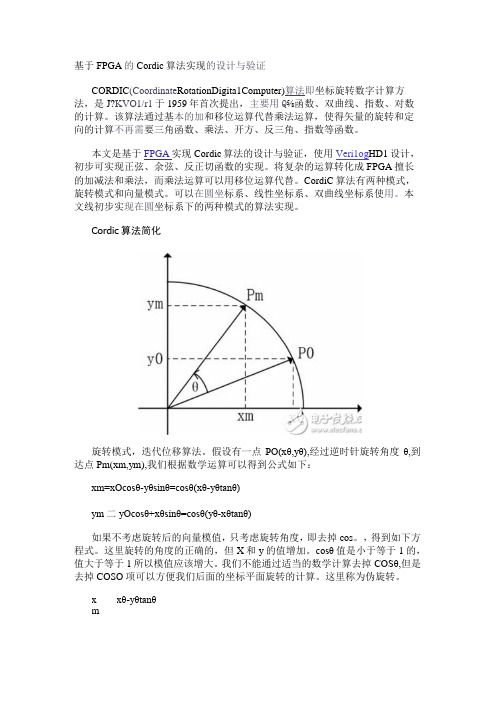
Cordic算法简化旋转模式,迭代位移算法。
假设有一点PO(xθ,yθ),经过逆时针旋转角度θ,到达点Pm(xm,ym),我们根据数学运算可以得到公式如下:xm=xOcosθ-yθsinθ=cosθ(xθ-yθtanθ)ym二yOcosθ+xθsinθ=cosθ(yθ-xθtanθ)如果不考虑旋转后的向量模值,只考虑旋转角度,即去掉cos。
,得到如下方程式。
这里旋转的角度的正确的,但X和y的值增加。
cosθ值是小于等于1的,值大于等于1所以模值应该增大。
我们不能通过适当的数学计算去掉COSθ,但是去掉COSO项可以方便我们后面的坐标平面旋转的计算。
这里称为伪旋转。
xθ-yθtanθxmym-yθ-xθtanθCordic的方法核心就是伪旋转,将旋转角θ细化成若干个大小固定的角度θi,规定满足tanBi=2^-i,通过一系列的迭代旋转,每次旋转θi,i为迭代次数,规定ΣBi的范围即旋转角度θ的范围为[-99.7,99.7]。
如果θ的大于这个范围则可通过三角运算操作转化到该范围的角度。
我们通过事先将所有每次旋转的角度计算出来,由于每次旋转的角度是固定的,所以经过i次旋转的EOi可能会超过O,所以就必须设置一个方向值di,如果旋转角度之和己经小于θ,则di为1下次旋转继续为顺时针旋转,如果旋转角度之和大于。
cordic算法详解

cordic算法详解转载自小一休哥的文章:/qq_39210023/article/details/77456031 目前,学习与开发FPGA的程序员们大多使用的是Verilog HDL语言(以下简称为Verilog),关于Verilog的诸多优点一休哥就不多介绍了,在此,我们将重点放在Verilog的运算操作上。
我们都知道,在Verilog中,运算一般分为逻辑运算(与或非等)与算术运算(加减乘除等)。
而在一开始学习Verilog 时,老司机一定会提醒我们,“切记,千万别用‘/’除、‘%’取模(有的也叫取余)和‘**’幂。
”这话说的不无道理,因为这三个运算是不可综合的。
但,需清楚理解的是,不可综合的具体意思为不能综合为简单的模块,当我们在程序中调用了这些运算时,‘/’除和‘%’取模在Quartus软件中是可以综合的,因此可以正常调用运行,但是会消耗一些逻辑资源,而且会产生延时,即这两个运算的处理时间会很长,可能会大于时序控制时钟的单周期时间。
此时呢,我们会建议你调用IP核来实现运算操作,虽然这样也会消耗许多逻辑资源,但产生的延时相对较小满足了你基本的需求。
问题好像迎刃而解了,可是仔细一想,除了这些运算,我们还剩下什么?对呀,三角函数,反三角函数,对数函数,指数函数呢,这些函数我们在高中就学习了的呀,难道在FPGA中就没有用武之地吗?有人会说,查找表呗,首先将某个运算的所有可能的输入与输出对一一罗列出来,然后放进Rom中,然后根据输入查表得到输出。
这个方法虽然有效的避免了延时问题,却是一个十分消耗资源的方法,不适合资源紧张的设计。
那么,就真的没有办法了吗?答案就是咱们今天的标题了,CORDIC,而且CORDIC是一个比较全能的算法,通过这一原理,我们可以实现三角函数,反三角函数,对数函数,指数函数等多种运算。
接下来,一休哥就带领大家来学习CORDIC的原理吧。
(题外话:请相信一休哥,本文不会让你感到太多痛苦~)本文将分三个小部分来展开介绍:1、CORDIC的基本原理介绍2、CORDIC的具体操作流程介绍3、CORDIC的旋转模式——Verilog仿真本文涉及到的全部资料链接:链接:/s/1gfrJzMj 密码:x92u一、CORDIC的基本原理介绍CORDIC算法是一个“化繁为简”的算法,将许多复杂的运算转化为一种“仅需要移位和加法”的迭代操作。
FPGA_ASIC-利用CORDIC算法在FPGA中实现可参数化的FFT
Yin
- X in
- X in - Yin
XOR
XOR
X
Y
图二 π / 4 预转的结构图
实现的电路图如图(二)所示,可以看到实现 π / 4 预旋转消耗的资源很少。经过 π / 4 旋转后的向量都被集中在[-π /4,+π /4]内,进行下一旋转的θn 的只需要从θn = arctan(1/4) 开始。节省了θn =atctan(+∞ )= π /2 和θn = atctan(1/2)=π /4 两次旋转。
据写入 FPGA 用 DMA 方式消耗
地址产生模块
控制模块
2048×10ns = 20.48us
。采用双缓冲的结构来
图六 可参数化的 FFT 计算模块的整体结构
实现 FFT 计算和数据 写入的并行处理。把
RAM 模块平均分成 2 个部分。当第 1 部分做计算时,可以向第 2 部分写入下次需要计算的
2048 个点。写完第 2 部分后,对第 2 部分内的数据启动 FFT 计算,同时开始向第 1 部分的
16 点 FFT 计算 模块
触发器组 ROM 模块
触发器组
输出 数据
输出 数据
单元来实现。RAM 采 用 32 位宽数据总线深 度为 4098,一个时钟 可以完成对一个数据 的读或写操作。需要 2048 个时钟才能把需 要计算的 2048 点全部 写入 RAM 内,时钟周
期为10ns ,为了把数
触发器组
2.3 CORDIC 循环结构 从对 CORDIC 基本计算单元的设计分析看出,基本计算单元结构整齐,便于循环结构
或者流水线结构实现。循环结构占用资源少,速度慢。流水线结构速度快,占用资源多。这
里采用循环结构实现 CORDIC 乘法器。其结构图如图三所示。
Xilinx CORDIC算法(非常经典)

) )
+ di ( 2 x
其中判决算子 di 决定旋转的方向是顺时针还是逆时针。di 的值取决于下面将要讨论的 操作模式 。 这里我们引入了名为 角度累加器 的第三个等式, 用于追踪每次迭代中旋转的角度的叠加 : z
(i + 1)
= z
(i)
– di θ
(i)
上述三个方程式为圆周坐标系中用于角度旋转的 CORDIC 算法的表达式。 在本章的后续部分中我们还将看到 CORDIC 算法被用于其它的坐标系,通过使用这些坐标系可以执行更大范围的函数计算。
很显然,每次旋转的方向都影响到最终要旋转的累积角度。在 – 99.7 ≤ θ ≤ 99.7 的范围内的任意角度都可以旋 i –i 转。 满足法则的所有角度的总和 tan θ = 2 为 99.7。 对于该范围之外的角度, 可使用三角恒等式转化成该范 围内的角度。 当然,角分辨率的数据位数与最终的精度有关。
Notes:
Top
关于 CORDIC 算法的细节问题,可参见下面的材料 : [1] R. Andraka. A survey of CORDIC algorithms for FPGA based computers. /cordic.htm [2] The CORDIC Algorithms. /ee/class/ee621/Lectures/L22.PDF [3] CORDIC Tutorial. /~geezer/embed/cordic.htm [4] M. J. Irwin. Computer Arithmetic. /~cg575/lectures/cse575-cordic.pdf
Notes:
Top
在 xy 坐标平面中 :
Pseudo-Rotation
- 1、下载文档前请自行甄别文档内容的完整性,平台不提供额外的编辑、内容补充、找答案等附加服务。
- 2、"仅部分预览"的文档,不可在线预览部分如存在完整性等问题,可反馈申请退款(可完整预览的文档不适用该条件!)。
- 3、如文档侵犯您的权益,请联系客服反馈,我们会尽快为您处理(人工客服工作时间:9:00-18:30)。
CORIDC 技术并不是什么新鲜的东西。事实上它可以追溯到 1957 年由 J. Volder 发表的一篇文章。在上个世纪 五十年代, 在大型实际的计算机中的实行移位相加受到了当时技术上的限制, 所以使用 CORDIC 变得非常必 要。到了七十年代,Hewlett Packard 和其他公司出产了手持计算器 , 许多计算器使用一个内部 CORDIC 单元来 计算所有的三角函数 ( 了解这件事的人们一定还记得,那时求一个角度的正切值需要延迟大约 1 秒中 )。 二十世纪八十年代,随着高速度乘法器与带有大存储量的通用处理器的出现, CORDIC 算法变得无关紧要了。 然而在二十一世纪的今天, 对于 FPGA 来说, CORDIC 一定是在 DSP 应用中 ( 诸如 多输入多输出 (MIMO), 波束形成以及其他自适应系统 ) 计算三角函数的备选技术。
August 2007, Version 3.8/21/07 For Academic Use Only. All Rights Reserved
Notes:
Top
关于 CORDIC 算法的细节问题,可参见下面的材料 : [1] R. Andraka. A survey of CORDIC algorithms for FPGA based computers. /cordic.htm [2] The CORDIC Algorithms. /ee/class/ee621/Lectures/L22.PDF [3] CORDIC Tutorial. /~geezer/embed/cordic.htm [4] M. J. Irwin. Computer Arithmetic. /~cg575/lectures/cse575-cordic.pdf
FPGAs for DSP
CORDIC 算法
4
Return
Return
DSPedia Home
Version 3.10/30/07
DSP Notes Menu
For Academic Use Only in Accordance with Licence-to-Use, see readme.pdf
2 + y2 = x1 1
2 + y2 x2 2
Developed by:
CORDIC 方法
i
Top
4.4
• CORDIC 方法的核心是 ( 伪 ) 旋转角度 θ ,其中 tan θ = 2-i。故方程为 : ˆ = x – y tan θ = x – y 2 –i x 2 1 1 1 1
–i ˆ y 2 = y 1 + x 1 tan θ = y 1 + x 1 2
i 1 2 3 4 5 6 7 8 9 10 11 12 13 tanθ 1 0.5 0.25 0.125 0.0625 0.03125 0.015625 0.0078125 0.00390625 0.001953125 0.000976563 0.000488281 0.000244141 Angle, θ 45.0000000000 26.5650511771 14.0362434679 7.1250163489 3.5763343750 1.7899106082 0.8951737102 0.4476141709 0.2238105004 0.1119056771 0.0559528919 0.0279764526 0.0139882271 cosθ 0.707106781 0.894427191 0.9701425 0.992277877 0.998052578 0.999512076 0.999877952 0.999969484 0.999992371 0.999998093 0.999999523 0.999999881 0.99999997
) )
+ di ( 2 x
其中判决算子 di 决定旋转的方向是顺时针还是逆时针。di 的值取决于下面将要讨论的 操作模式 。 这里我们引入了名为 角度累加器 的第三个等式, 用于追踪每次迭代中旋转的角度的叠加 : z
(i + 1)
= z
(i)
– di θ
(i)
上述三个方程式为圆周坐标系中用于角度旋转的 CORDIC 算法的表达式。 在本章的后续部分中我们还将看到 CORDIC 算法被用于其它的坐标系,通过使用这些坐标系可以执行更大范围的函数计算。
Top
4.3
即旋转的角度是正确的,但是 x 与 y 的值增加 cos–1 θ 倍 ( 由于 cos–1 θ > 1,所以模值变大。 • 注意我们 并不能 通过适当的数学方法去除 cos θ 项 , 然而随后我们发现 去除 cos θ 项可以简化坐标平面旋转的计算操作。
August 2007, Version 3.8/21/07 For Academic Use Only. All Rights Reserved
Developed by:
笛卡尔坐标平面旋转
x 2 = x 1 cos θ – y 1 sin θ y 2 = x 1 sin θ + y 1 cos θ
Top
4.2
• 在 xy 坐标平面上将点 ( ( x 1, y 1 ) 旋转 θ 角度到点 ( x 2, y 2 ) 的标准方法如 下所示 :
y2
Developed by:
移位 - 加法算法
(i + 1) (i + 1) (i) (i) –i ( i )
Top
4.6
• 因此 , 原始的算法现在已经被减化为使用向量的伪旋转来表示的迭代 移 位 - 相加 算法 : x y = (x = (y – di ( 2 y ) ) + di ( 2 x ) )
Notes:
Top
在 xy 坐标平面中 :
Pseudo-Rotation
ˆ ,x ˆ (x 1 2) ˆ R
2 + y2 x R 1 1 ˆ = -----------R = --------------------cos θ cos θ
(x2, y2)
Rotation
θ
(x1, y1)
R
R =
因此经过伪旋转之后,向量 R 的模值将增加 1 ⁄ cos θ 倍。 向量旋转了正确的角度 , 但模值出现错误。
(i + 1)
= z
(i)
– di θ ( i )
(Angle Accumulator)
角度的累加,与
where d i = +/- 1
• 符号 di 是一个判决算子,用于确定旋转的方向。
di的值由旋转的方向来决 定,刚好tana是一个奇 函数,tana=-tan(-a),cos (a)是一个偶函数,所以 角度的累加,当为逆时 针的时候,di为1,反时 针的di为-1,而角度a无 需变为-a,还是用 tana,cosa就可以了
Developed by:
角度累加器
•· 前面所示的伪旋转现在可以表示为 (对每次迭代) : x y
(i + 1) (i + 1)
Top
4.5
= x = y
(i) (i)
– di ( 2 y ) + di ( 2 x )
–i ( i )
–i ( i )
坐标值的累加
• 在这里我们引入第三个方程,被称为角度累加器,用来在每次迭代过程 中追踪累加的旋转角度 : z
THIS SLIDE IS BLANK
简介
如何在 FPGA 上执行这些运算 ? 可以使用查找表 , 或是迭代法
Top
4.1
• 目前的 FPGA 具有 许多 乘法器和加法器。 然而各种各样的通信技术和 矩阵算法则需要三角函数、平方根等的运算。
• 本节介绍了 CORDIC 算法 ; 这是一个 “ 移位相加 ” 算法 , 允许计算不同的 三角函数 , 例如 : • • • x2 + y2 cos θ, tan θ, sin θ 包括除法和对数函数在内的其它函数。
i 0 1 2 3 4
θ
i
(Degrees)
i –i tan θ = 2 1 0.5 0.25 0.125 0.0625
45.0 26.555051177... 14.036243467... 7.125016348... 3.576334374...
August 2007, Version 3.8/21/07 For Academic Use Only. All Rights Reserved
y1
θ x2 x1
• 这被称为是平面旋转、 向量旋转或者线性 ( 矩阵 ) 代数中的 Givens 旋 转。
August 2007, Version 3.8/21/07 For Academic Use Only. All Rights Reserved
Notes:
Top
上面的方程组同样可写成矩阵向量形式 :
很显然,每次旋转的方向都影响到最终要旋转的累积角度。在 – 99.7 ≤ θ ≤ 99.7 的范围内的任意角度都可以旋 i –i 转。 满足法则的所有角度的总和 tan θ = 2 为 99.7。 对于该范围之外的角度, 可使用三角恒等式转化成该范 围内的角度。 当然,角分辨率的数据位数与最终的精度有关。
Notes:
Top
在这里,我们把变换改成了迭代算法。我们将各种可能的旋转角度加以限制,使得对任意角度 θ 的旋转能够通 (i) –i 过一系列连续小角度的旋转迭代 i 来完成。 旋转角度遵循法则 : tan θ = 2 , 遵循这样的法则,乘以正切项变 成了移位操作。 前几次迭代的形式为 : 第 1 次迭代 : 旋转 45o; 第 2 次迭代 : 旋转 26.6o, 第 3 次迭代 : 旋转 14o 等。
• 下面的表格指出用于 CORDIC 算法中每个迭代 (i) 的旋转角度 (精确到 9 位小数 ):