Specification
SPECIFICATIONS 产品说明书

SPEC19-08 10/15)Outlet: 1-1/4” tube outlet for 1-1/4” slip joint connectionACCESS PANELSHeavy-gauge steel with vandal-resistant screws. Provides access for easy hook-up of all plumbing connections. SUGGESTED SPECIFICATIONSUnit shall include powder-coated finish with vandal-resistant pushbutton actuation, vandal-resistant bubbler with integral hood guard, and contour-formed rounded basin to reduce splash and prevent standing water. Fountain shall comply with ANSI 117:1 and ADA for visual and motion disabilities. The manufacturer shall certify the unit to meet the requirements of NSF/ANSI 61, and the Safe Drinking Water Act.Outdoor TubularModel LK4410FRK is shown.2222 Camden Court Oak Brook, IL In keeping with our policy of continuing product improvement, Elkay reserves the right to change specification without notice. Please visit for the most current version.ModelColor OptionADA CompliantNSF/ANSI 61CertifiedLK4410FRK*(Refer to Finish Color Options)••* Select color option to complete model number. Example: LK4410FRK EVG Beige Black Blue Brown Evergreen GrayOrange Purple Terracotta Red White YellowN o w Av a i l a bl ei n12Co l o r s !Each 4410 FR consists of 2 cartons of the following:• Fountain• Single Freeze-Resistant Valve System - 97243CThis specification describes an Elkay product with design, quality and functional benefits to the user. When making a comparison of other producer’s offerings, be certain these features are not overlooked.FINISH COLOR OPTIONS – Choose color option to complete your model number, add as suffix example: LK4410FRK EVGMatte finish: Evergreen = EVG Gloss finish: Beige = BGE Gray = GRY Terracotta = TER Black = BLK Orange = ORN White = WHT Blue = BLU Purple = PUR Yellow = YLWBrown = BRN Red = REDOPTIONS• Hose Bib (Locking) - LK4471LHB * (Choose color option to complete your model number)• Hose Bib (Non-Locking) - LK4470NLHB* (Choose coloroption to complete your model number)• Direct Bury Kit - 97890CPrinted in the U.S.A.Page 2MODEL LK4410FRK Outdoor TubularFreeze-Resistant FountainOPERATING PRESSURES:Supply water 20 – 105 psi maximumMOUNTING INSTRUCTIONS and PLUMBING INSTRUCTIONSSite and drainage excavation is required for fountain installation. Refer to owner’s manual for site preparation details. Provide solid, well-drained surface to mount pedestal fountain (concrete pad recommended) with adequate support (300 lb. load minimum). (6) 3/8” minimum fasteners (not included) should be attached securely to mounting surface in order to secure fountain, (Refer to rough-in diagram), and be sure to allow an opening for the freeze-resistant valve in the ground as shown in the diagram below). Refer to local codes for any additional requirements.Locate and install plumbing through ground as required. Assemble fountain to prepared site and mounting pad.NOTE: Fountain is not furnished with service valve.Position pedestal over plumbing and secure base to fasteners. Remove access panels and connect supply and water lines. Turn on water supply and check for leaks. Refer to owner’s manual for detailed instructions.Reassemble access panels to pedestal. Trap and service stop not included.2222 Camden Court Oak Brook, IL 。
外贸常用英语 foreign trade English

外贸中常用英语外贸Foreign Trade,1.(specification, particulars)包括质量(quality),价格(price),以及包装方式(packing method),包装材料(packing materials)quality质量,quantity数量)2.客户购买(purchase),下采购订单(place the order),(purchase order,PO)。
供应商vendor。
PO#,ORDERED RFOM,BILL TOSHIP TOSHIP DATETERMS OF PRICETERMS OF PAYMENT以及产品数量ITEMS, DESCRIPTION, QUANTITY, UNIT PRICE,TOTAL PRICE仓库warehouse。
库存inventory。
纸PAPER RP=permanent, RR=removable卷roll纸箱carton,内盒inner carton/box,外箱master carton。
唛头(shipping mark):净重:net weight 毛重gross weight 警示性标志warning mark 标签label 条码barcode 原产地country of origin印刷printing检验inspection3.QASigned sample签样Inspection report4.集装箱containerLoading containerWarehouse 仓库5.Import 进口export 出口Forwarder 货代Shipping documents 运输单据Enclosed/attachment 附件PI=Proforma InvoiceSales contract 销售合同Commercial invoicePacking listPort of loadingPort of dischargeBL 提单报关单bill of entryCertificate of Origin 原产地证ETD=estimated time of departure ETA=estimated time of arrival 6.FinancialTelegraphic transfer 电汇T/T Compensation赔偿Month:JanuaryFebruaryMarchAprilMayJuneJulyAugustSeptemberOctoberNovemberDecemberWeek:SundayMondayTuesdayWednesdayThursdayFridaySaturday。
PM300-Specification

Specification correct at 1st January 2013. Piezotest reserves the right to change specifications without notice when necessary.PiezoMeter System PM300 Technical SpecificationHigh Precision,Piezoelectric d 33 Testing System Measuring d 33 in four ranges, capacitance and tan dPiezoelectric Testsd 33 – Very High Range d 33 range: 100 to 10,000 pC/N Accuracy: ± 2% ± 1 pC/N Loading: 1.0uF d 33 - High Ranged 33 range: 10 to 1000 pC/N Accuracy: ± 2% ± 1 pC/N Loading: 1.0uF d 33 - Low Ranged 33 range: 1 to 100 pC/N Accuracy: ± 2% ± 0.1 pC/N Loading: 1.0uF d 33 – Very Low Range d 33 range: 0 to 10 pC/NAccuracy: ± 2% ± 0.01 pC/N Loading: 0.1uF d 31 & d 15Adapters are available for various sample geometries, and supplied separately. PolaritySample polarity is indicated for all ranges. Test FrequencyFrequency Range: 30 Hz to 300 Hz Setting: steps of: 1 Hz Accuracy: ± 0.1 HzCalibration is at 110 Hz. Other frequencies may be used to tune away from system resonances with large samples. Force amplitudeTesting is by an oscillatory force, variable by user setting between 0.05 to 0.50 N.Static force of approximately 10 N used to grip the sample. This may be different for force head units with non-standard suspension (see section on ‘Sample Size’ below).Dielectric TestsCapacitanceCapacitance range: 10 pF to 0.1 mF Accuracy (< 100pF): ± 2% ± 0.1 pF Accuracy (> 100pF): ± 2% ± 1 pF Test frequency: 1 kHzTan dTan d range: 0.0000 to 0.2000 Accuracy: ± 2% ± 0.0001General OperationResponse Timed 33 Only: 5s to 1% of final reading C and tan d: 2s to 1% of final reading d 33, C and tan d: 10s to 1% of final reading Sample SizeMaximum dimensions:50 mm in polarisation direction.68 mm perpendicular (i.e. maximum diameter of a symmetrically supported disc is 136 mm) Maximum sample mass:1 Kg with standard suspension.Different suspension mechanisms can be provided to special order for more massive samples or very thin or soft samples. CalibrationThe system is supplied fully calibrated and tested. d 33 calibration may be checked using the reference sample provided. In normal use, recalibration is recommended annually. Calibration may be carried out to customer reference using the remote interface. Data StorageThe standard PM300 will store up to 100 measurements. All results are numbered and stored along with the test frequency and the measurement range in use.Data is retained when the PiezoMeter is switched off.Stand-Alone Operation40 character by 4 line alphanumeric liquid crystal display showing sample number, d 33, test frequency and operation mode. Simple keypad to control all PiezoMeter functions for stand-alone operation.Printing facility when used directly with standard PC printer, providing tabulated output and statistical analysis. Remote OperationThe PiezoMeter may be controlled by a computer, equipped with Windows 98, 2000, XP or Vista. A free serial port is required. All PiezoMeter functions may be controlled. Remote control software for Windows, supplied separately, also allows real-time calculation of e T 33, g 33 and g 31 using sample dimensions supplied by the user. Remote InterfaceIndustry standard RS-232C interface, configured as data terminal equipment (DTE) using 9 pin D-connector.RS-232 parameters: 9600 baud, 1 stop bit, no parity. Connection is by a standard PC serial file transfer cable (supplied).Printer InterfaceIndustry standard parallel printer interface, using 25 pin D-connector, configured as for a standard PC. Connection is by a standard PC printer cable (supplied). Power supply220-240V a.c. 50-60Hz 0.5A or 100-120V a.c. 50-60Hz 1A (Specify with order). Temperature LimitsStorage: 0°C to 50°C Operating: 10°C to 40°C System calibrated: 25°C Physical dimensionsElectronics unit: 350 x 250 x 100 mm Force unit: 145 x 150 x 175 mm. Total Unpacked Weight: Approx. 13 kg Total Packed Weight: Approx. 19 kgFor more details, or to arrange a demonstration, contact :-European Union:Unit 204, 2 Old Brompton RoadLondon SW7 3DQ UNITED KINGDOMTel: +44 (0)20 7748 2248 Fax: +44 (0)20 7748 2249e-mail: sales@Asia Pacific & Global:10 Anson Road#31-10 International Plaza(S) 088834 SINGAPORETel: +65 6224 9005 Fax: +65 6224 9945e-mail: sales@OTESTPIEZ。
Chapter 7 Specification Choosing A Functional Form
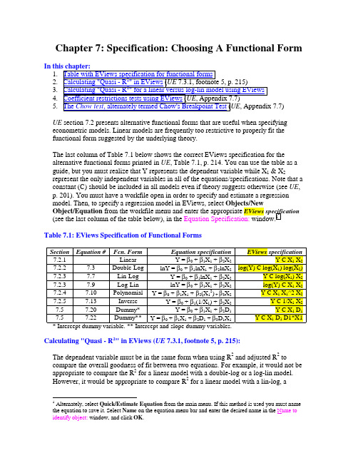
Chapter 7: Specification: Choosing A Functional Form1.2.3.4.5.UE section 7.2 presents alternative functional forms that are useful when specifying econometric models. Linear models are frequently too restrictive to properly fit thefunctional form suggested by the underlying theory.The last column of Table 7.1 below shows the correct EViews specification for thealternative functional forms printed in UE, Table 7.1, p. 214. You can use the table as a guide, but you must realize that Y represents the dependent variable while X1 & X2represent the only independent variables in all of the equations/specifications. Note that a constant (C) should be included in all models even if theory suggests otherwise (see UE, p. 201). You must have a workfile open in order to specify and estimate a regression model. Then, to specify a regression model in EViews, select Objects/NewObject/Equation from the workfile menu and enter the appropriate EViews specification (see the last column of the table below), in the Equation Specification: window.1Table 7.1: EViews Specification of Functional FormsSection Equation # Fcn. Form Equation specification EViews specification7.2.1 ---- Linear Y = β0 + β1X1 + β2X2Y C X1 X27.2.2 7.3 Double-Log lnY = β0 + β1lnX1 + β2lnX2log(Y) C log(X1) log(X2)7.2.3 7.7 Lin-Log Y = β0 + β1lnX1 + β2X2Y C log(X1) X27.2.3 7.9 Log-Lin lnY = β0 + β1X1 + β2X2log(Y) C X1 X27.2.4 7.10 PolynomialY = β0 + β1X1 + β2(X12) + β3X2Y C X1 X1^2 X27.2.5 7.13 Inverse Y = β0 + β1(1/X1) + β2X2Y C 1/X1 X27.5 7.20 Dummy* Y = β0 + β1X1 + β2D1Y C X1 D17.5 7.22 Dummy**Y = β0 + β1X1 + β2D1 + β3D1X1Y C X1 D1 D1*X1 * Intercept dummy variable. ** Intercept and slope dummy variables.Calculating "Quasi - R2" in EViews (UE 7.3.1, footnote 5, p. 215):The dependent variable must be in the same form when using R2 and adjusted R2 to compare the overall goodness of fit between two equations. For example, it would not be appropriate to compare the R2 for a linear model with a double-log or a log-lin model.However, it would be appropriate to compare R2 for a linear model with a lin-log, a1 Alternately, select Quick/Estimate Equation from the main menu. If this method is used you must namethe equation to save it. Select Name on the equation menu bar and enter the desired name in the Name to identify object: window, and click OK.polynomial, or an inverse functional form model. Likewise, it would be appropriate to compare R2 for double-log and log-lin functional form models. In order to demonstrate the process, the car acceleration data introduced in UE, Exercise 16, p. 234, will be used to demonstrate the process of calculating the quasi-R2. The steps below show how tocompare the goodness of fit for models using S (the number of seconds it takes a car to accelerate from 0 to 60 miles per hour) as the dependent variable versus using the natural log of S as the dependent variable. In both models, the independent variables are thesame as the original model printed at the top of UE, p. 236.Calculating "Quasi - R2" for a linear versus a log-lin model using EViews:Step 1. Open the EViews workfile named Cars7.wk1.Step 2. Select Objects/New Object/Equation on the workfile menu bar, enter S C T E P H in the Equation Specification: window, and click OK.Step 3. Select Name on the equation menu bar, write linear in the Name to identify object: window, and click OK. Minimize the equation object named linear.Step 4. Select Objects/New Object/Equation on the workfile menu bar, enter log(S) C T E PH in the Equation Specification: window (i.e., the log-lin functional form), and clickOK.Step 5. Select Name on the equation menu bar, write loglin in the Name to identify object: window, and click OK.Step 6. Select Forecast on the equation menu bar, select S in the Forecast of:2 window, enter SF in the Forecast name: window, uncheck the two boxes in the Output: window (the only objective here is to create a forecast series, not a forecast evaluation), and click OK.A new series named SF appears in the workfile window.Steps 7, 8 & 9 calculate the quasi-R2 for this regression (UE 7.3.1, footnote 5, p. 215). Step 7. Minimize the equation window, select Genr on the workfile menu bar, type numerator=(S-SF)^2 in the Enter equation: window, and click OK (this step generates the un-summed variable in the numerator of the quasi-R2 equation).Step 8. Select Genr on the workfile menu bar, type denominator=(S-@mean(S))^2 in the Enter equation: window, and click OK (this step generates the un-summed variable in the denominator of the quasi-R2 equation).Step 9. To calculate the quasi-R2, type the following equation in the command window and press Enter: scalar quasir2=1-(@sum(numerator)/@sum(denominator)). A new variable named quasir2 will appear in the workfile window. Double click on it and the value for the quasi-R2 will be displayed in the lower left of the screen (0.783958974). The quasi-R2 calculated in Step 9 (i.e., 0.78) is in-between the R2 from the linear model estimated in Step 2 (i.e., 0.71) and the R2 from the log-lin model estimated in Step 5 (i.e., 0.81).2 The Forecast procedure in EViews gives you the option of forecasting the transformed dependentvariable (i.e., LOG(S) in this case) or the original variable (i.e., S in this case). Select S, since thecomputation of quasi-R2 requires converting of LOG(S) to S by taking the anti-log of the dependentvariable (this can also be done by using the EViews command @exp(LOG(S)).Coefficient restrictions tests using EViews (UE, Appendix 7.7):The F-test can be used to test a wide range of hypothesis concerning regressioncoefficients. For example, suppose that the claim was made that when a car has a manual transmission it increases its acceleration speed (i.e., decreases the number of seconds it takes to accelerate from 0 to 60 miles per hour) just as much as adding 100 horsepower to the car. Translating this into the language of UE, Equation 7.28, p. 235, this means that the absolute value of the coefficient on T i is 100 times larger than the absolute value of the coefficient on H i. Just looking at the size of the estimated coefficients, it appears that you can easily reject the hypothesis because the absolute value of the coefficient on T i is only about 41.5 times larger than the absolute value of the coefficient on H i (divide the coefficient on T i by the coefficient on H i). However, these coefficients are just estimates.Follow these steps to carry out an F-test for the null hypothesis that the absolute value of the coefficient on T i is 100 times larger than the absolute value of the coefficient on H i. : Step 1. Open the EViews workfile named Cars7.wk1.Step 2. Select Objects/New Object/Equation on the workfile menu bar, enter S C T E P H in the Equation Specification: window, and click OK.Step 3. Select Name on the equation menu bar, write EQ01 in the Name to identify object: window, and click OK.Step 4. Select View/Coefficients Tests/Wald-Coefficient Restrictions … on the equation menu bar, enter -C(2)=-100*C(5) in the Coefficients separated by commas: window, and click OK to reveal the following output:3Wald Test:Equation: EQ01Null Hypothesis: -C(2)=-100*C(5)Probability 0.124472F-statistic 2.485049Probability 0.114933Chi-square 2.485049The null hypothesis is -C(2)=-100*C(5), since variable T is the second coefficient and variable H is the fifth coefficient in the EViews Estimation Output from Step 2. The F-statistic compares the residual sum of squares computed with and without the restrictions imposed. If the restrictions are valid, there should be little difference in the two residual sum-of-squares and the F-value should be small. Based on the Wald Test: results table, the null hypothesis cannot be rejected at the 5% level of significance. The calculated F-statistic of 2.49 is less than the critical F-value of 4.14. The critical F-value can be found in UE, Table B-2, p. 609 for 1 degree of freedom in the numerator and 33 (interpolate between the 30 and 40) degrees of freedom in the denominator or EViews can calculate3 The coefficients should be referred to as C(1), C(2), and so on (do not use series names). Multiplecoefficient restrictions must be separated by commas and the restrictions should be expressed as equations involving estimated coefficients and constants. The coefficients should be referred to as C(1), C(2), and so on (do not use series names).its value.4 The reported probability is the marginal significance level of the F-test. Itsupports this result in that rejecting the null hypothesis would be wrong less than 12.44% of the time.The Chi-square statistic is equal to the F-statistic times the number of restrictions under test. In this example, there is only one restriction and so the two test statistics areidentical with the p-values of both statistics indicating that we cannot reject the nullhypothesis, that the absolute value of the coefficient on T i is 100 times larger than theabsolute value of the coefficient on H i, at the 10% significance level. The 10%significance critical value for the χ2 test can be found in UE, Table B-8, p. 619 to be 2.71.The Chow test, alternately termed Chow's Breakpoint Test (UE, Appendix 7.7): Chow's Breakpoint Test divides the data into two sub-samples.5 It then estimates thesame equation for each sub-sample separately, to see whether there are significantdifferences in the estimated equations. A significant difference indicates a structuralchange in the relationship.Follow these steps to apply the Chow breakpoint test, as described in UE, pp. 241-242, to determine whether there was a structural change in the demand for chicken in 1976:Step 1. Open the EViews workfile named Chick6.wf1.Step 2. Select Objects/New Object/Equation on the workfile menu bar, enter Y C PC PB YD in the Equation Specification: window, and click OK.Step 3. Select Name on the equation menu bar, write EQ01 in the Name to identify object: window, and click OK.Step 4. Select View/Stability Tests/Chow Breakpoint Test… on the equation menu bar, enter 1976 in the Enter one date (observation) for the Forecast Test or one or more dates for the Breakpoint Test: window, and click OK to reveal the following output:Chow Breakpoint Test: 1976F-statistic 4.542962 Probability 0.004498Log likelihood ratio 17.98027 Probability 0.001245EViews reports two test statistics for the Chow breakpoint test. The F-statistic is based on the comparison of the restricted and unrestricted sum of squared residuals. EViewscalculates the F-statistic using the formula printed in UE, Equation 7.36, p. 242. In this4 To have EViews calculate the 5% critical F-value for this problem, type the following equation in thecommand window =@qfdist(0.95,1,eq01.@regobs-eq01.@ncoefs), press Enter and view the followingvalue on the status bar in the lower left of the screen . For the 10% critical F-value type =@qfdist(0.90,1,eq01.@regobs-eq01.@ncoefs) in the command window, and press Enter and view the following value on the status bar in the lower left of the screen .5 One major drawback of the breakpoint test is that each sub-sample requires at least as many observationsas the number of estimated parameters. This may be a problem if, for example, you want to test forstructural change between wartime and peacetime where there are only a few observations in the wartime sample.case, the calculated F-statistic of 4.54 exceeds the critical F-value of 2.63 for the 5% level of significance so the null hypothesis of no structural change can be rejected. The critical F-value can be found in UE, Table B-2, p. 609 for 4 degrees of freedom in the numerator and 36 (interpolate between the 30 and 40) degrees of freedom in the denominator or EViews can calculate its value.6 The reported probability is the marginal significance level of the F-test. It supports this result in that rejecting the null hypothesis would be wrong less than 0.4498% of the time.The log likelihood ratio statistic is based on the comparison of the restricted and unrestricted maximum of the log likelihood function. The LR test statistic has an asymptotic χ2 distribution with degrees of freedom equal to (m-1)*(k+1) under the null hypothesis of no structural change, where m is the number of sub-samples and k is the number of independent variables in the model (i.e., m = 2 in this case because one breakpoint is selected and k = 3). The calculated value for LR test statistic of 17.98 exceeds of 9.49 for the 5% level of significance and 13.28 for the 1% level of significance so the null hypothesis of no structural change can be rejected.7 The reported probability is the marginal significance level of the χ2 test. It supports this result in that rejecting the null hypothesis would be wrong less than 0.1245% of the time.6 To have EViews calculate the 5% critical F-value for this problem, type the following equation in the command window =@qfdist(0.95,eq01.@ncoef,eq01.@regobs-2*eq01.@ncoef), press Enter and view the following value on the status bar in the lower left of the screen .7The critical value for the χ2 test can be found in UE, Table B-8, p. 619.。
SPECIFICATION COMPLIANCE FORM
Incubator
Incubator: Automatic for use in neonatal intensive care unit, microprocessor controlled, with double wall hood, with digital servo/air control, dimension for hood: approx. 108.5x64x91.5cm of the mainbody, dimension for cabinet: 112.5x66.5x73cm, dimension for mattress: 63.5x35.5cm, mattress tilting angle: 0 to 12 detress, aperture for tubes 4, combined silent window rotation and closing system, transfer handle and 4 swivelling castors, DM 125mm, control mode: air/skin/oxygen, indication range of oxygen concentration: 0%RH-99%RH, control range of oxygen conc. 20%RH-60RH, monitor console platform to fit vital monitor or pulse oximeter, power consumption: 700VA, electric supply: 220/240V+/-10%, strarting temperature 25 degree celsius, warm up time<35 min, measurment accuracy +/-0.1DC, sound level <55Db, air filter 0.5mcm, air filter capacity 99%, oxygen inlet with automatic safety device limiting the oxygen flow to 35%, adjustable hygrometer 40~80%, skin temperature display range 22-45DC, skin temperature control range 34~38DC, air temperature display 5~40DC, air temperature control 20~39DC, humidity control display 30-90DC, possible technical monitoring via PC through communication plug, sound and flash alarm, with 1 spare skin probe, 1 communication cable to connect with PC, 2 IV poles
CTD中 怎样写 JUSTIFICATION OF SPECIFICATION

CTD 中怎样写JUSTIFICATION OF SPECIFICATION(质量标准合理性)的讨论*最近做一个只有部颁标准的产品的CTD,做到JUSTIFICATION OF SPECIFICATION部分,狂晕啊,EP,USP甚至ChP中都没有收载这个产品,这种情况下,这一部分内容怎么做?请大家发表高见.对于这种情况,一般来说,一方面你应当要和采用你们原产品作为原料的制剂厂家联系,因为他们的质量标准应当要和他们的采购标准一致,而他们所制订的质量标准必须是通过实验数据证明要能保证其制剂的质量。
另一方面,你可以参考相关的ICH指导原则。
Justification of Specification (S.4.5)质量标准的合理性说明(第S.4.5章)Justification for the proposed drug substance specifications should be provided. The justification should be based on relevant development data (S.2.6), information on impurities (S.3.2), standards in an official compendium, batch analyses data (S.4.1), stability studies (S.7), toxicology data, and any other relevant data. The discussion in this section should unify data and information that are located in other sections of the application, either by reference or in summary. When justifying the specification, an applicant should consider data from (1) drug substance batches used in evaluating clinical efficacy and safety, bioavailability, and/or bioequivalence, (2) primary stability batches, and(3) relevant development and process validation batches, when available. If multiple drug substance manufacturing sites or processes are planned, it can be valuable to consider data from these sites and processes in establishing the tests and acceptance criteria. This is particularly true when there is limited initial experience with the manufacture of the drug substance at any particular site or by any particular method. Justification for an in-process test that is used in lieu of a drug substance test should be included in S.2.4.应当要提供拟定原料药质量标准的合理性说明。
Test Specification考试规范

• According to the regulation, the test specification includes the testing theoretical construct and related specific skills. And it has the clear and concise expression of the testing content. So it helps the teachers make exam questions in line with the test validity and make the testing content representative and targication and Overall Design
• The problems in designing a test: In order to reduce the task of marking examination papers, we use lots of objective question types. • The imbalance of testing items: Maybe the exam intends to test the skills of listening, speaking, reading and writing, but in fact, the exam lacks the testing item of speaking.
• Examples: The assessment of construct validity firstly focus on the the elaboration of the ability structure: Whether the definition of the ability is based on the theory? Is the definition is clear? Do the testing skills belong to the ability category? Whether the test meets the what the test specification requires the construct validity? whether the testing content is representive and appropriate?
国际化项目中Specification(技术规格书)的知识要点及应用
2 技术规格 书的内容和与 图纸的关
“ 图纸 就 是工 程 师 的语言 ” ,设 计 师利 用 图纸作 为载 体 来传 达他 的设计 意 图和 思 路 ,对 整 个工 程 有着 举 足轻 重 的 作用 。 如果 将 整个 工 程 比喻成 一 个 人 ,图 纸就 是 身体 , 它撑 起 了工 程 的全 部质 量 ,而 技 术规 格 书就 是血 液 ,赋 予
的 理 论 研 究 、现 状 分析 , 并 结 合 在 国 际 化 项 目 中 的 实践 经 验 ,论 述 了我 国设 计 师应 当 掌 握 的 关 于 技 术 规 格 书 的 一 些 知
识要点 ,为顺利承接 国际化运作模 式的项 目打下基础。 关键词 :国外设计项 目 国际化运作模式 技术规格书 知识要点 编制 中图分 类号 :T U 2 0 1 文献标识码:B 文章编号:1 0 0 4 — 1 0 0 1 ( 2 0 1 4 ) 0 5 — 0 6 0 8 — 0 3
了整 个工 程 鲜 活 的生命 。 图纸 的主要 任 务是 形 象地 表 现 出 各 个 设计 元 素 的 大 小 、形 式 、位 置 和 互 相 的 关 系等 等 信
书进行估算。第三是采购部门 ,可以根据技术规格书上规
定 的材 料和 设 备进 行 采购 。 第 四是 监理 人 员 ,技 术 规格 书 作者简介 :周静瑜 ( 1 9 7 3 一),女 ,硕士 ,高级工程师 。 通讯地址 :上海市石门二路2 5 8 号8 楼 ( 2 0 0 0 4 1 )。
人 把 技 术规 格 书 当作标 书 ,认 为技术 规 格 书就 是业 主 给 分
息。 而技 术 规格 书 所包 含 的 内容 却是 各 种材 料 、 系统 、设
备 、现场 和 非现 场 的安 装 工 艺等 等 的质 量控 制 ,具 体 有 :
冲压小知识
TEEP=冲床嫁动率,SPM=模具正常生产中的速度,OUT=几列几支(几出几). 3.冲程=模高=冲床在下死点时的模具高度. 4.REV=文件版次. 5.PITCH=送料长度. 6.SENSOR=检知器距离 7.送料TIMING=送料放松时间. 8.PART NUMBER=P/N=料号. 9.LOT NUMBER=L/N=批号. 10.PERCENT PER MILLION=PPM=百万分之一. 11.SPECIFICATION=SPEC=规格. 12.STATISTICAL PROCESS CONTROL=SPC=统计制程管制. 13.TERMINAL=端子. 14.PIECES=PCS=个(根,块).
TEEP=冲床嫁动率,SPM=模具正常生产中的速度,OUT=几列几支(几出几). 3.冲程=模高=冲床在下死点时的模具高度. 4.REV=文件版次. 5.PITCH=送料长度. 6.SENSOR=检知器距离 7.送料TIMING=送料放松时间. 8.PART NUMBER=P/N=料号. 9.LOT NUMBER=L/N=批号. 10.PERCENT PER MILLION=PPM=百万分之一. 11.SPECIFICATION=SPEC=规格. 12.STATISTICAL PROCESS CONTROL=SPC=统计制程管制. 13.TERMINAL=端子. 14.PIECES=PCS=个(根,块).
TEEP=冲床嫁动率,SPM=模具正常生产中的速度,OUT=几列几支(几出几). 3.冲程=模高=冲床在下死点时的模具高度. 4.REV=文件版次. 5.PITCH=送料长度. 6.SENSOR=检知器距离 7.送料TIMING=送料放松时间. 8.PART NUMBER=P/N=料号. 9.LOT NUMBER=L/N=批号. 10.PERCENT PER MILLION=PPM=百万分之一. 11.SPECIFICATION=SPEC=规格. 12.STATISTICAL PROCESS CONTROL=SPC=统计制程管制. 13.TERMINAL=端子. 14.PIECES=PCS=个(根,块).
specification

• Environmental considerations and requirements • Quality control requirements, acceptance sampling, inspections(安全检查), acceptance criteria (验收标准) • Person, office, or agency responsible for enforcement of the specification. • Completion and delivery. • Provisions for rejection, rehearing (复查), corrective measures
Sometimes the term specification is used in connection with a data sheet (or spec sheet). A data sheet describes the technical characteristics of an item or product. It can be published by a manufacturer to help people choose products or to help use the products. A data sheet is not a technical specification as described in this article.
Guidance and content
• Descriptive title, number, identifier, etc. of the specification • Date of last effective revision and revision designation • A logo or trademark to indicate the document copyright, ownership and origin • Table of Contents (TOC), if the document is long • Person, office, or agency responsible for questions on the specification, updates, and deviations. • The significance, scope or importance of the specification and its intended use.
Product Specification 产 品 规 格 书
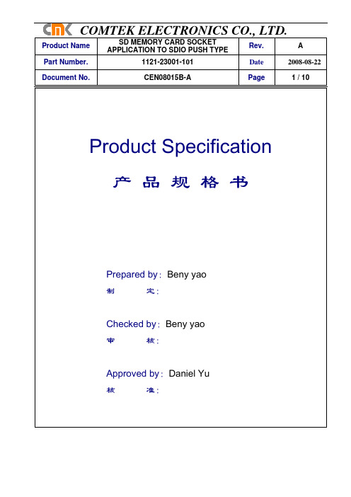
Part Number.1121-23001-101 Date2008-08-22 Document No.CEN08015B-A Page 1 / 10Product Specification产品规格书Prepared by:Beny yao制定:Checked by:Beny yao审核:Approved by:Daniel Yu核准:Part Number.1121-23001-101 Date2008-08-22 Document No.CEN08015B-A Page 2 / 101. SCOPE(适用范围) (3)2. REFERENCE DOCUMENTS(参考文件) (3)3. FEATURE & DIMENSIONS (特征及尺寸) (3)3.1. PRODUCT DIMENSION(产品尺寸) (3)3.2. PCB/PANEL LAYOUT (印刷电路板布局) (3)3.3. MATERIAL(材料) (4)3.4. MECHANICAL & ELECTRICAL CHARACTERISTIC (机械及电气特性) (4)3.5. PACKAGING(包装) (4)3.6. MARKING(标识) (4)3.7 TRANSPORTATION(运输) (4)3.8 STORAGE(存贮) (4)4. ENVIRONMENTAL(环境要求) (5)4.1. SOLDERABILITY(可焊性) (5)4.2. RESISTANCE TO SOLDER HEAT(耐焊接热) (5)4.2.1. Wave Soldering (波峰焊) (5)4.2.1.1. Preheat(预热) (5)4.2.1.2. Soldering(焊接) (5)4.2.1.3. Cool Down (冷却) (5)4.2.2. INFRARED REFLOW(红外线回流焊).............................................................. . (5)4.2.2.1. Preheat(预热)........................................................................................ . (5)4.2.2.2. Soldering(焊接)...................................................................................... . (5)4.2.2.3. Cool Down (冷却).................................................................................... .. (5)4.3. CLEANING (清洗) (5)5. PERFORMANCE AND TEST DESCRIPTION (性能及测试) (6)5.1. REQUIREMENT(要求) (6)5.2. TEST CONDITION(测试条件) (6)5.3. SAMPLE SELECTION(样品选择) (6)5.4. TEST SEQUENCE(测试顺序) (6)6. QUALITY ASSURANCE PROVISIONS (品质保证) (6)TABLE I:PERFORMANCE REQUIREMENTS .......................................7~8 TABLE II:PRODUCT QUALIFICATION TEST SEQUENCE (9)TABLE III:REFLOW SOLDERING PROFILE (10)Part Number.1121-23001-101 Date2008-08-22 Document No.CEN08015B-A Page 3 / 10PRODUCT SPECIFICATION1. SCOPE(适用范围)This product specification defines the product performance and the test methods to ascertain theperformance of the SD CARD., which is designed and manufactured by CMK本产品规格书规定了由旭竑电子设计生产的 SD CARD连接器产品的特性及测试方法.2. REFERENCE DOCUMENTS(参考文件)MIL-STD-1344A Test method for electrical connector (电子连接器测试方法)MIL-STD-202F Test method for electrical components (电子零件测试方法)EIA364 Test method for electrical components (电子零件测试方法)JIS C 0051 Test method for electrical components (电子零件测试方法)MIL-G-45204C Specification for gold plating (镀金规格)IEC-512-3 IEC standard for current carrying capacity tests(IEC电流测试标准)QQ-N-290A Specification for nickel plating (镀镍规格)MIL-P-81728A Specification for tin/lead plating (镀锡铅规格)MIL-T-10727B Specification for tin plating (镀锡规格)UL498 UL standard for safety of attachment plug and receptacle(UL安规要求标准)EN/ISO5961 Determination of total lead & cadmium content ( 总铅和总镉含量测定)EN1122 Determination of total lead & cadmium content ( 总铅和总镉含量测定)EN13346 Determination of heavy metals content ( 重金属含量测定)EPA3052 Determination of total lead & cadmium content ( 总铅和总镉含量测定)3. FEATURE & DIMENSIONS (特征及尺寸)3.1. PRODUCT DIMENSION (产品尺寸)These connectors shall have the dimensions as shown in customer drawing。
标准文献(standard,specification,rules)

标准文献(standard,specification,rules)标准:国家标准GB3935.1-83对标准的定义为:为重复性事物和概念所作的统一规定。
它以科学、技术和实践经验的综合成果为基础,经有关方面协商一致,由主管机关批准,以特定形式发布,作为共同遵守的准则和依据标准文献:一般是由技术标准、管理标准及其他具有标准性质的类似文件所组成的特种科技文献体系。
有广义和狭义之分。
构成标准文献的三个条件:1)标准是经过有关方面的共同努力所取得的成果,它是集体劳动的结晶2)标准必须经过一个公认的权威机构或授权单位的批准认可3)标准必须随着科学技术的发展而更新换代,即不断进行补充、修订或废止标准文献的特点:•数量庞大,发展迅速•指令性、指导性兼有•自成体系,独立完成•种类繁多,重复交叉•更新迅速,修订频繁标准文献的分类:按使用范围划分:国际标准:如国际标准化组织(ISO)标准、国际电工委员会(IEC)标准区域标准:如全欧标准(EN)国家标准:如我国国家标准(GB)、美国国家标准(ANSI)行业标准:如美国石油学会标准(API)企业标准:如美国波音飞机公司标准(BAC)按内容划分:基础标准(即标准的标准)、原材料标准、环保标准、安全卫生标准等按成熟程度划分:法定标准:具有法律性质的必须遵守的标准推荐标准:是制订和分布标准的机构建议优先遵循的标准试行标准:指内容不够成熟,尚有待在使用实践中进一步修订、完善的标准标准文献的作用:1)通过标准文献可了解各国经济政策、技术政策、生产水平、资源状况和标准水平2)在科研、工程设计、工业生产、企业管理、技术转让、商品流通中,采用标准化的概念、术语、符号、公式、量值、频率等有助于克服技术交流的障碍3)国内外先进的标准可供推广研究、改进新产品、提高新工艺和技术水平依据4)是鉴定工程质量、校验产品、控制指标和统一试验方法的技术依据5)可以简化设计、缩短时间、节省人力、减少不必要的试验、计算,能够保证质量、减少成本6)进口设备可按标准文献进行装备、维修配制某些零件7)有利于企业或生产机构经营管理活动的统一化、制度化、科学化和文明化国内标准及其检索概况:1956年开始制订标准;1978年5月国家标准总局成立,9月中国标准化协会加入ISO组织标准等级(分四级):国家标准:必须在国家范围内统一和实施的标准,由国家标准化管理委员会主管行业标准:指行业的标准化主管部门发布的在某一行业范围内统一和实施的标准地方标准:指在没有国家标准和国家标准不能满足需要的情况下依据某地区的特殊情况在该地区范围内统一的标准企业标准:由企业或上级有关机构批准发布的标准。
Abstraction vs.Specification

用部分代替整体,汉译时不宜直译出具体概念,应
该进行概括归纳,表达出其指代的整体意思。
Example
As a consequence of this example in the family……
(Life in a Violin Case)
由于家中已有这样的前车之鉴……
It is comforting to know that some very old and very simple ways of getting from one place to another still
like a sport: your eagerness and knowledge and quickness
make you a good reader. (The Pleasure of Reading)
阅读是心智的乐事,颇有点儿像运动:心情热切、知识丰富、
思维敏捷才能造就一个好的读者。
Example
Example
Man for the field and woman for the hearth; Man for the sword and woman for the needle she. Man with the head and woman with the heart:
男人耕作女持家; 男上战场女纺纱。
work.
(The Ancient and the Modern) 发觉一些非常古老简单的方法经历变迁依然管用,多么让人高兴呀。
Example
Man for the field and woman for the hearth;
男人适于农耕,女人适于家务;
Man for the sword and woman for the needle .
1.Generalspecification基本

2.1Electrical characteristics 电气性能 Item 项目
2.1.1 Contact Resistance 接触电阻
2.1.2 Insulation Resistance 绝缘电阻
2.1.3 Withstand Voltage 耐电压
Test condition 测试条件
Push force:(Operation force)X2。 测定时的负荷:操作方向动作力基准值的 2 倍 Measurement tool: Contact resistance meter 测定器:微电流接触电阻计(1kHz,20mV,5~50mA) DC 250V(Between terminals) frame for 1 minute. 不相接的两端子间、端子与塑胶间施加 DC250V 电压,持 续 1 分钟测量 AC 250V (Between terminals) frame for 1 minute. 不相接的两端子间、端子与塑胶间施加 AC250V 电压,持 续 1 分钟测量
GoodTimor
东莞市佳汶塑胶电子有限公司
WRITTEN BY
CHECKED BY
APPROVED BY
共6页 第1页
2.2 Mechanical Characteristics 机械性能
Item 项目
Test condition 测试条件
Performance 规格
2.2.1
Operations Force 动作力
2.2.6
Solderbility 可焊性
GoodTimor
东莞市佳汶塑胶电子有限公司
After sprated flux 涂上助焊剂后 temperature:245±5℃ 温度:245±5℃ Soldering time:3±0.5sec 焊接时间:3±0.5 秒
ASTM Specification A 312
SPECIFICATION FOR SEAMLESS AND WELDED AUSTENITIC STAINLESS STEEL PIPESSA-312/SA-312M(Identical to ASTM Specification A312/A312M-95b except forclarified heat treatment requirements in5.2.2.)1.Scope1.1This specification covers seamless and straight-seam welded austenitic steel pipe intended for high-temperature and general corrosive service.NOTE1—When the impact test criterion for a low-temperature service would be15ft·lbf[20J]energy absorption or15mils[0.38 mm]lateral expansion,some of the austenitic stainless steel grades covered by this specification are accepted by certain pressure vesselor piping codes without the necessity of making the actual test.For example,Grades TP304,TP304L,and TP347are accepted by the ASME Pressure Vessel Code,Section VIII Division1,and by the Chemical Plant and Refinery Piping Code,ANSI B31.3,for serviceat temperatures as low as−425°F[−250°C]without qualification by impact tests.Other AISI stainless steel grades are usually acceptedfor service temperatures as low as−325°F[−200°C]without impact testing.Impact testing may,under certain circumstances,be required.For example,materials with chromium or nickel content outside the AISI ranges,and for material with carbon content exceeding0.10%,are required to be impact tested under the rules of ASME SectionVIII Division1when service temperatures are lower than−50°F[−45°C].1.2Grades TP304H,TP309H,TP309HCb,TP310H,TP310HCb,TP316H,TP321H,TP347H,and TP348Hare modifications of Grades TP304,TP309Cb,TP309S,TP310Cb,TP310S,TP316,TP321,TP347,and TP348, and are intended for high-temperature service.1.3Optional supplementary requirements are providedfor pipe where a greater degree of testing is desired. These supplementary requirements call for additional tests to be made and,when desired,one or more of these may be specified in the order.1.4Table X1.1lists the dimensions of welded and seamless stainless steel pipe as shown in ANSI B36.19. Pipe having other dimensions may be furnished provided such pipe complies with all other requirements of this specification.4771.5Grades TP321and TP321H have lower strength requirements for pipe manufactured by the seamless process in nominal wall thicknesses greater than3⁄8in.[9.5mm].1.6The values stated in either inch-pound units or SI units are to be regarded separately as standard. Within the text,the SI units are shown in brackets.The values stated in each system are not exact equivalents; therefore,each system must be used independently of the bining values from the two systems may result in nonconformance with the specification.The inch-pound units shall apply unless the“M”designation of this specification is specified in the order.NOTE2—The dimensionless designator NPS(nominal pipe size) has been substituted in this standard for such traditional terms as “nominal diameter,”“size,”and“nominal size.”2.Referenced Documents2.1ASTM Standards:A262Practices for Detecting Susceptibility to Intergran-ular Attack in Austenitic Stainless SteelsA370Test Methods and Definitions for Mechanical Test-ing of Steel ProductsA450/A450M Specification for General Requirements for Carbon,Ferritic Alloy,and Austenitic Alloy Steel TubesA530/A530M Specification for General Requirements for Specialized Carbon and Alloy Steel PipeE112Test Methods for Determining the Average Grain SizeE213Practice for Ultrasonic Examination of Metal Pipe and TubingSA-312/SA-312M1998SECTION IIE381Method of Macroetch Testing,Steel Bars,Billets, Blooms,and ForgingsE426Practice for Electromagnetic(Eddy-Current)Ex-amination of Seamless and Welded Tubular Products, Austenitic Stainless Steel,and Similar AlloysE527Practice for Numbering Metals and Alloys(UNS) 2.2ANSI Standards:B1.20.1Pipe Threads,General PurposeB36.10Welded and Seamless Wrought Steel PipeB36.19Stainless Steel Pipe2.3AWS Standard:A5.9Corrosion-Resisting Chromium and Chromium-Nickel Steel Welding Rods and Electrodes2.4Other Standard:SAE J1086Practice for Numbering Metals and Alloys (UNS)2.5Other Standard:SNT-TC-1A Personnel Qualification and Certification in Nondestructive Testing3.Ordering Information3.1Orders for material to this specification should include the following,as required,to describe the desired material adequately:3.1.1Quantity(feet,centimeters,or number of lengths),3.1.2Name of material(austenitic steel pipe),3.1.3Process(seamless or welded),3.1.4Grade(Table1),3.1.5Size(NPS or outside diameter and schedule number or average wall thickness),3.1.6Length(specific or random)(Section10),3.1.7Endfinish(Section on Ends of SpecificationA530/A530M),3.1.8Optional requirements(Section7),3.1.9Test report required(Certification Section of Specification A530/A530M),3.1.10Specification number,and3.1.11Special requirements or any supplementary requirements selected,or both.4784.General Requirements4.1Material furnished under this specification shall conform to the applicable requirements of the current edition of Specification A530/A530M unless otherwise provided herein.5.Materials and Manufacture5.1Manufacture:5.1.1The pipe shall be made by the seamless or an automatic welding process,with no addition offiller metal in the welding operation.5.1.2“Welded pipe NPS14and smaller shall havea single longitudinal weld.Welded pipe of a size larger than NPS14may be produced by forming and welding two longitudinal sections offlat stock when approved by the purchaser.All weld tests,examinations,inspections, or treatments are to be performed on each weld seam.”5.1.3At the manufacturer’s option,pipe may be either hotfinished or coldfinished.5.1.4The pipe shall be free of scale and contaminating iron particles.Pickling,blasting or surfacefinishing is not mandatory when pipe is bright annealed.The purchaser may request that a passivating treatment be applied.5.2Heat Treatment:5.2.1All pipe shall be furnished in the heat-treated condition in accordance with the requirements of Table 2.The heat-treatment procedure,except for“H”grades, S30815,S31272,S31254,S32654,N08367,and N08904 shall consist of heating the pipe to a minimum tempera-ture of1900°F[1040°C]and quenching in water or rapidly cooling by other means.5.2.2All H grades shall be furnished in the solution-treated condition.For H grades,separate solution heat treatments are required for solution annealing;in-process heat treatments are not permitted as a substitute for the separate solution annealing treatments.A solution anneal-ing temperature above1950°F[1065°C]may impair the resistance to intergranular corrosion after subsequent ex-posure to sensitizing conditions in TP309HCb, TP310HCb,TP321,TP321H,TP347,TP347H,TP348, and TP348H.When specified by the purchaser,a lower temperature stabilization or re-solution anneal shall be used subsequent to the initial high temperature solution anneal(see Supplementary Requirement S6).PART A—FERROUS MATERIAL SPECIFICATIONS SA-312/SA-312M5.3Grain Size:5.3.1The grain size of Grade UNS S32615,as determined in accordance with Test Methods E112, shall be No.3orfiner.5.3.2The grain size of TP309H,TP309HCb,TP310H and TP310HCb,as determined in accordance with Test Methods E112,shall be No.6or coarser.5.3.3The grain size of TP321H,as determinedin accordance with Test Methods E112,shall be No.7or coarser.6.Chemical Composition6.1The steel shall conform to the requirements asto chemical composition prescribed in Table1.7.Product Analysis7.1At the request of the purchaser,an analysis of one billet or one length offlat-rolled stock from each heat,or two pipes from each lot shall be made by the manufacturer.A lot of pipe shall consist of the following number of lengths of the same size and wall thickness from any one heat of steel:NPS Designator Lengths of Pipe in LotUnder2400or fraction thereof2to5200or fraction thereof6and over100or fraction thereof7.2The results of these analyses shall be reportedto the purchaser or the purchaser’s representative,and shall conform to the requirements specified in Section6. 7.3If the analysis of one of the tests specified in 7.1does not conform to the requirements specified in Section6,an analysis of each billet or pipe from the same heat or lot may be made,and all billets or pipe conforming to the requirements shall be accepted.8.Tensile Requirements8.1The tensile properties of the material shall con-form to the requirements prescribed in Table3.9.Mechanical Tests and Grain SizeDeterminations Required9.1Transverse or Longitudinal Tension Test—One tension test shall be made on a specimen for lots of479not more than100pipes.Tension tests shall be made on specimens from two tubes for lots of more than 100pipes.NOTE3—The term“lot,”for mechanical tests,applies to all pipe of the same diameter and wall thickness(or schedule)which are produced from the same heat of steel and subjected to the same finishing treatment:(1)in a continuous heat-treatment furnace,or (2)in a batch-type heat-treatment furnace,equipped with recording pyrometers and automatically controlled within a50°F[30°C]range, the larger of:(a)Each200ft[60m]or fraction thereof or,(b) That pipe heat treated in the same batch furnace charge.9.2Flattening Test—For material heat treated ina batch-type furnace,flattening tests shall be made on 5%of the pipe from each heat-treated lot.For material heat treated by the continuous process,this test shall be made on a sufficient number of pipe to constitute 5%of the lot,but in no case less than two lengths of pipe.9.2.1For welded pipe a transverse-guided face bend test of the weld may be conducted instead of a flattening test in accordance with the method outlined in the steel tubular product supplement of Test Methods and Definitions A370.The ductility of the weld shall be considered acceptable when there is no evidence of cracks in the weld or between the weld and the base metal after bending.Test specimens from5%of the lot shall be taken from the pipe or test plates of the same material as the pipe,the test plates being attached to the end of the cylinder and welded as a prolongation of the pipe longitudinal seam.9.3Hydrostatic Test—Each length offinished pipe shall be subjected to the hydrostatic test in accordance with Specification A530/A530M,unless specifically exempted under the provisions of9.4and9.5.9.4For pipe whose dimensions equal or exceed NPS 10,the purchaser with the agreement of the manufacturer may waive the hydrostatic test requirement when in lieu of such test the purchaser performs a system test. Each length of pipe furnished without the completed manufacturer’s hydrostatic test shall include with the mandatory markings the letters“NH.”9.5Nondestructive Examination:9.5.1As an alternative to the hydrostatic test,and when specified by the purchaser,each pipe shall be examined with a nondestructive test in accordance with Practice E213,or E426.Unless specifically called out by the purchaser,the selection of the nondestructive electric test will be at the option of the manufacturer. The range of pipe sizes that may be examined by each method shall be subject to the limitations in the scope of the respective practices.SA-312/SA-312M1998SECTION II9.5.2The following information is for the benefitof the user of this specification.9.5.2.1The reference standards defined in9.5.2.2 through9.5.2.5are convenient standards for calibrationof nondestructive testing equipment.The dimensionsof these standards should not be construed as the minimum size imperfection detectable by such equipment.9.5.2.2The ultrasonic testing(UT)can be per-formed to detect both longitudinally and circumferen-tially oriented defects.It should be recognized that different techniques should be employed to detect differ-ently oriented imperfections.The examination may not detect short,deep defects.9.5.2.3The eddy-current testing(ET)referencedin this specification,(Practice E426),has the capabilityof detecting significant discontinuities,especially the short abrupt type.9.5.2.4A purchaser interested in ascertainingthe nature(type,size,location,and orientation)of discontinuities that can be detected in the specific application of these examinations should discuss this with the manufacturer of the tubular product.9.5.3Time of Examination:9.5.3.1Nondestructive testing for specification acceptance shall be performed after all mechanical processing,heat treatments,and straightening opera-tions.This requirement does not preclude additional testing at earlier stages in the processing.9.5.4Surface Condition:9.5.4.1All surfaces shall be free of scale,dirt, grease,paint,or other foreign material that could inter-fere with interpretation of test results.The methods used for cleaning and preparing the surfaces for exami-nation shall not be detrimental to the base metal orthe surfacefinish.9.5.4.2Excessive surface roughness or deep scratches can produce signals that interfere with the test.9.5.5Extent of Examination:9.5.5.1The relative motion of the pipe and the transducer(s),coil(s),or sensor(s)shall be such thatthe entire pipe surface is scanned,except as in9.5.5.2.9.5.5.2The existence of end effects is recog-nized,and the extent of such effects shall be determinedby the manufacturer,and,if requested,shall be reportedto the purchaser.Other nondestructive tests may be480applied to the end areas,subject to agreement between the purchaser and the manufacturer.9.5.6Operator Qualifications:9.5.6.1The test unit operator shall be certified in accordance with SNT-TC-1A,or an equivalent recog-nized and documented standard.9.5.7Test Conditions:9.5.7.1For eddy-current testing,the excitation coil frequency shall be chosen to ensure adequate penetration yet provide good signal-to-noise-ratio.9.5.7.2The maximum eddy-current coil fre-quency used shall be as follows:On specified walls up to0.050in.-100KHz maxOn specified walls up to0.150in.-50KHz maxOn specified walls up to0.150in.-10KHz max9.5.7.3Ultrasonic-For examination by the ultra-sonic method,the minimum nominal transducer fre-quency shall be2.00MHz and the maximum nominal transducer size shall be1.5in.(a)If the equipment contains a reject noticefilter setting,this shall remain off during calibration and testing unless linearity can be demonstrated at that setting.9.5.8Reference Standards:9.5.8.1Reference standards of convenient length shall be prepared from a length of pipe of the same grade,size(NPS,or outside diameter and schedule or wall thickness),surfacefinish and heat treatment condi-tion as the pipe to be examined.9.5.8.2For Ultrasonic Testing,the reference ID and OD notches shall be any one of the three common notch shapes shown in Practice E213,at the option of the manufacturer.The depth of each notch shall not exceed121⁄2%of the specified nominal wall thickness of the pipe or0.004in.,whichever is greater.The width of the notch shall not exceed twice the depth. Notches shall be placed on both the OD and ID surfaces.9.5.8.3For Eddy-Current Testing,the reference standard shall contain,at the option of the manufacturer, any one of the following discontinuities:(a)Drilled Hole—The reference standard shall contain three or more holes,equally spaced circumferen-tially around the pipe and longitudinally separated by a sufficient distance to allow distinct identification of the signal from each hole.The holes shall be drilled radially and completely through the pipe wall,with care being taken to avoid distortion of the pipe whilePART A—FERROUS MATERIAL SPECIFICATIONS SA-312/SA-312Mdrilling.one hole shall be drilled in the weld,if visible. Alternately,the producer of welded pipe may chooseto drill one hole in the weld and run the calibration standard through the test coils three times with the weld turned at120deg.on each pass.The hole diameter shall vary with NPS as follows:NPS Designator Hole Diameter1⁄20.039in.(1mm)above1⁄2to1-1⁄40.055in.(1.4mm)above1-1⁄4to20.071in.(1.8mm)above2to50.087in.(2.2mm)above50.106in.(2.7mm)(b)Transverse Tangential Notch-Using a round toolorfile with a1⁄4in.(6.4mm)diameter,a notch shallbefiled or milled tangential to the surface and transverseto the longitudinal axis of the pipe.Said notch shall have a depth not exceeding12-1⁄2%of the specified nominal wall thickness of the pipe or0.004in.[0.102 mm],whichever is greater.(c)Longitudinal Notch-A notch0.031in.or less in width shall be machined in a radial plane parallel tothe tube axis on the outside surface of the pipe,to have a depth not exceeding12-1⁄2%of the specified wall thickness of the pipe or0.004in.,whichever is greater.The length of the notch shall be compatible with the testing method.9.5.8.4More or smaller reference discontinuities,or both,may be used by agreement between the pur-chaser and the manufacturer.9.5.9Standardization Procedure:9.5.9.1The test apparatus shall be standardizedat the beginning and end of each series of pipes ofthe same size(NPS or diameter and schedule or wall thickness),Grade and heat treatment condition,and at intervals not exceeding4h.More frequent standardiza-tion may be performed at the manufacturer’s optionor may be required upon agreement between the pur-chaser and the manufacturer.9.5.9.2The test apparatus shall also be standard-ized after any change in test system settings,changeof operator,equipment repair,or interruption due to power loss,process shutdown or when a problem is suspected.9.5.9.3The reference standard shall be passed through the test apparatus at the same speed and test system settings as the pipe to be tested.9.5.9.4The signal-to-noise ratio for the reference standard shall be2-1⁄2to1or greater.Extraneous signals caused by identifiable causes such as dings, scratches,dents,straightener marks,etc.,shall not be481considered noise.The rejection amplitude shall be ad-justed to be at least50%of full scale of the readout display.9.5.9.5If upon any standardization,the rejection amplitude has decreased by29%(3dB)of peak height from the last standardization,the pipe since the last calibration shall be rejected.The test system settings may be changed,or the transducer(s),coil(s)or sensor(s) adjusted,and the unit restandardized,but all pipe tested since the last acceptable standardization must be retested for acceptance.9.5.10Evaluation of Imperfections:9.5.10.1Pipes producing a signal equal to or greater than the lowest signal produced by the reference standard(s)shall be identified and separated from the acceptable pipes.The area producing the signal may be reexamined.9.5.10.2Such pipes shall be rejected if the test signal was produced by imperfections that cannot be identified or was produced by crack or crack-like imper-fections.These pipes may be repaired per Sections11 and12.To be accepted,a repaired pipe must pass the same non-destructive test by which it was rejected,and it must meet the minimum wall thickness requirements of this specification.9.5.10.3If the test signals were produced by visual imperfections such as:(a)Scratches;(b)Surface roughness;(c)Dings;(d)Straightener marks;(e)Cutting chips;(f)Steel die stamps;(g)Stop marks,or;(h)Pipe reducer ripple.The pipe may be accepted based on visual examina-tion provided the imperfection is less than0.004in.[0.1mm]or12-1⁄2%of the specified wall thickness (whichever is greater).9.5.10.4Rejected pipe may be reconditioned and retested providing the wall thickness is not decreased to less than that required by this or the product specifica-tion.The outside diameter at the point of grinding may be reduced by the amount so removed.To be accepted, retested pipe shall meet the test requirement.9.5.10.5If the imperfection is explored to the extent that it can be identified as non-rejectable,the pipe may be accepted without further test providingSA-312/SA-312M1998SECTION IIthe imperfection does not encroach on the minimum wall thickness.9.6Grain Size—Grain size determinations on gradesTP309H,TP309HCb,TP310H,TP310HCb,and UNSS32615shall be made on the same number of tubesas prescribed for theflattening test.10.Lengths10.1Pipe lengths shall be in accordance with the following regular practice:10.1.1Unless otherwise agreed upon,all sizes from NPS1⁄8to and including NPS8are available in a length upto24ft[Note4]with the permissible range of15to24ft [Note4].Short lengths are acceptable and the number and minimum length shall be agreed upon between the manu-facturer and the purchaser.NOTE4—This value(s)applies when the inch-pound designationof this specification is the basis of purchase.When the“M”designationof this specification is the basis of purchase,the corresponding metric value(s)shall be agreed upon between the manufacturer and the purchaser.10.1.2If definite cut lengths are desired,the lengths required shall be specified in the order.No pipe shallbe under the specified length and not more than1⁄4in. [6mm]over that specified.10.1.3No jointers are permitted unless otherwise specified.11.Workmanship,Finish,and Appearance11.1Thefinished pipes shall be reasonably straight and shall have a workmanlikefinish.Imperfections maybe removed by grinding,provided the wall thicknessesare not decreased to less than that permitted in Section8of Specification A530/A530M.12.Repair by Welding12.1For welded pipe whose diameter equals or exceeds NPS6,and whose nominal wall thickness equals or exceeds0.200,weld repairs made with the addition of compatiblefiller metal may be made tothe weld seam with the same procedures specified for plate defects in the section on Repair by Welding of Specification A530/A530M.12.2Weld repairs of the weld seam shall not exceed 20%of the seam length.48212.3Weld repairs shall be made only with the gas tungsten-arc welding process using the same classifica-tion of barefiller rod qualified to the most current AWS Specification A5.9as the grade of stainless steel pipe being repaired and as shown in Table4.12.4Pipes that have had weld seam repairs with filler metal shall be uniquely identified and shall be so stated and identified on the certificate of tests. 13.Certification13.1In addition to the information required by Specification A530/A530M,the certification shall state whether or not the material was hydrostatically tested.If the material was nondestructively tested,the certification shall so state and shall show which standard practice was followed and what reference discontinuities were used.14.Marking14.1In addition to the marking specified in Specifica-tion A530/A530M,the marking shall include the NPS(nominal pipe size)and schedule,heat numbering and NH when hydrotesting is not performed and ET when eddy-current testing is performed or UT when ultrasonic testing is performed.The marking shall also include the manufacturer’s private identifying mark,the marking requirement of9.4,if applicable,and whether seamless or welded.For Grades TP304H,TP316H, TP321H,TP347H,TP348H,and S30815,the marking shall also include the heat number and heat-treatment lot identification.If specified in the purchase order,the marking for pipe larger than NPS4shall include the weight.ernment Procurement15.1Scale Free Pipe for Government Procurement:15.1.1When specified in the contract or order, the following requirements shall be considered in the inquiry,contract or order,for agencies of the U.S. Government where scale free pipe or tube is required. These requirements shall take precedence if there is a conflict between these requirements and the product specifications.15.1.2The requirements of Specification A530/A 530M for pipe and Specification A450/A450M for tubes shall be applicable when pipe or tube is ordered to this specification.PART A—FERROUS MATERIAL SPECIFICATIONS SA-312/SA-312M15.1.3Pipe and tube shall be one of the following grades as specified herein:Grade UNS DesignationTP304S30400TP304L S30403TP304N S30451TP316S31600TP316L S31603TP316N S31651TP317S31700TP317L S31703TP321S32100TP347S3470015.1.4Part Number:Example:ASTM A312/A312M Pipe304NPS12 SCH40S SMLSSpecification Number.......................ASTM A312Pipe.....................................PGrade (304)NPS (12)Wall.....................................0.375SMLS OR WELDED.......................SML15.1.4.1Specification Number.......................ASTM A312Tube.....................................TGrade (304)Outside Diameter...........................0.250Wall.....................................0.035SMLS OR WELDED.......................WLD48315.1.5Ordering Information—Orders for material under this specification shall include the following in addition to the requirements of Section3:15.1.5.1Pipe or tube,15.1.5.2Part number,15.1.5.3Ultrasonic inspection,if required,15.1.5.4If shear wave test is to be conducted in two opposite circumferential directions,15.1.5.5Intergranular corrosion test,and15.1.5.6Level of preservation and packing re-quired.16.Keywords16.1austenitic stainless steel;seamless steel pipe; stainless steel pipe;steel pipe;welded steel pipe.SA-312/SA-312M1998SECTION IIT A B L E 1C H E M I C A L R E Q U I R E M E N T SC o m p o s i t i o n ,%U N S C a r b o n ,M a n g a n e s e C o l u m b i u m D e s i g n a t i o n m a x m a x P h o s p h o r u s ,S u l f u r ,p l u s T a n t a l u m ,N i t r o g e n G r a d e[N o t e (1)][N o t e (2)][N o t e (2)]m a x m a xS i l i c o n N i c k e l C h r o m i u m M o l y b d e n u m T i t a n i u m T a n t a l u m m a x [N o t e (3)]V a n a d i u mC o p p e r C e r i u m B o r o n A l u m i n u mT P 304S 304000.082.000.0400.0300.75m a x 8.00–11.018.0–20.0........................T P 304H S 304090.04–0.102.000.0400.0300.75m a x 8.00–11.018.0–20.0........................T P 304L S 304030.0352.000.0400.0300.75m a x 8.00–13.018.0–20.0........................[N o t e (5)]T P 304N S 304510.082.000.0400.0300.75m a x 8.00–11.018.0–20.0............0.10–0.16.........T P 304L N S 304530.0352.000.0400.0300.75m a x 8.00–11.018.0–20.0............0.10–0.16.........T P 309C b S 309400.082.000.0450.0300.75m a x 12.0–16.022.0–24.00.75m a x ...10×C ............m i n ,1.10m a x T P 309H S 309090.04–0.102.000.0400.0300.75m a x 12.0–15.022.0–24.0.....................T P 309H C b S 309410.04–0.102.000.0450.0300.75m a x 12.0–16.022.0–24.00.75m a x ...10×C .........m i n ,1.10m a x T P 309S S 309080.082.000.0450.0300.75m a x 12.0–15.022.0–24.00.75m a x ..................T P 310C b S 310400.082.000.0450.0300.75m a x 19.0–22.024.0–26.00.75m a x ...10×C ............m i n ,1.10m a x T P 310H S 310090.04–0.102.000.0400.0300.75m a x 19.0–22.024.0–26.0.....................T P 310H C b S 310410.04–0.102.000.0450.0300.75m a x 19.0–22.024.0–26.00.75m a x ...10×C .........m i n ,1.10m a x T P 310SS 310080.082.000.0450.0300.75m a x 19.0–22.024.0–26.00.75m a x ..................S 312720.08–0121.5–2.000.0300.0150.3–0.714.0–16.014.0–16.01.0–1.40.3–0.60.004–0.008T P 316S 316000.082.000.0400.0300.75m a x 11.0–14.016.0–18.02.00–3.00.....................[N o t e (4)]T P 316H S 316090.04–0.102.000.0400.0300.75m a x 11.0–14.016.0–18.02.00–3.00.....................[N o t e (4)]T P 316L S 316030.0352.000.0400.0300.75m a x 10.0–15.016.0–18.02.00–3.00.....................[N o t e (5)]T P 316N S 316510.082.000.0400.0300.75m a x 11.0–14.016.0–18.02.00–3.000.10–0.16.........[N o t e (4)]T P 316L N S 316530.0352.000.0400.0300.75m a x 11.0–14.016.0–18.02.00–3.00.........0.10–0.16.........[N o t e (4)]T P 317S 317000.082.000.0400.0300.75m a x 11.0–14.018.0–20.03.00–4.00.....................T P 317L S 317030.0352.000.0400.0300.75m a x 11.0–15.018.0–20.03.00–4.00.....................T P 321S 321000.082.000.0400.0300.75m a x 9.00–13.017.0–20.0...[N o t e (6)]..................T P 321H S 321090.04–0.102.000.0400.0300.75m a x 9.00–13.017.0–20.0...[N o t e (7)]..................T P 347S 347000.082.000.0400.0300.75m a x 9.00–13.017.0–20.0......[N o t e (8)]...............T P 347H S 347090.04–0.102.000.0400.0300.75m a x 9.00–13.017.0–20.0......[N o t e (9)]...............T P 347L N S 347510.005–2.000.0400.0300.75m a x 9.00–13.017.0–20.0......0.2–0.5...0.06–0.10...............0.020[N o t e (11)]T P 348S 348000.082.000.0400.0300.75m a x 9.00–13.017.0–20.0......[N o t e (8)]0.10............T P 348H S 348090.04–0.102.000.0400.0300.75m a x 9.00–13.017.0–20.0......[N o t e (9)]0.10............484。
specification

1.0 DESCRIPTIONThis work shall consist of the construction of all structures or parts of structures to be composed of Portland cement concrete pipe culverts. Concrete cast using blended cement such as Portland cement with ground granulated blastfurnace slag and /or pulverized fuel ash shall also be classified under this work. The work shall be carried out all in accordance with this Specification and the lines, levels, grades, dimensions and cross-sections shown on the Drawings.The Contractor to submit a list of supplies from whom he wishes to purchase the materials necessary for the execution of works, sampling, submission of test certificates,etc.2.0 MATERIALSCementThe cement to be used throughout the work shall be Portland cement obtained from an approved manufacturer. The source of supply of cement for concrete in the guide way structures to be kept constant for each structure. Single source of cement for use in concrete for the same visible structural unit (for instance, single pier, single portal or single viaduct span) is required to avoid variation in concrete color tone. The cement shall be described under one of the following headings:(a) Ordinary Portland CementThe cement shall comply with MS 522.(b) Rapid Hardening Portland CementThe cement shall comply with MS 522.(c) Moderate Sulphate Resisting Portland CementThe cement shall comply with MS 1037 or BS 4027.(d) Sulphate Resisting Portland CementThe cement shall comply with MS1037 or BS 4027.(e) Portland Slag Cement/Portland Blastfurnace CementThe cement shall comply with MS 1389 or BS 146.。
- 1、下载文档前请自行甄别文档内容的完整性,平台不提供额外的编辑、内容补充、找答案等附加服务。
- 2、"仅部分预览"的文档,不可在线预览部分如存在完整性等问题,可反馈申请退款(可完整预览的文档不适用该条件!)。
- 3、如文档侵犯您的权益,请联系客服反馈,我们会尽快为您处理(人工客服工作时间:9:00-18:30)。
remove the metal chips;
完成品通过机器人竖直放置在料箱里
9
工艺/Process
Finished goods is vertically placed in box by robot
锯切精度 ±0.1mm
10
工艺/Process
Sawing accuracy ±0.1mm
加工直径 φ60mm 厚度 1.5mm 材料,循环时间<=30 秒;
日本三菱 1.5kw Japan Mitsubishis 1.5kw
台湾东元 Taiwan DONGYUAN 台湾威纶通 7 寸(中英文) Taiwan Weiluntong 1 inches (Chinese -
English interface) 日本施耐德
Japan Schneider 日本施耐德
1
PRODUCTION ENGINEERING CI
MANUFACTURING CO., LTD
7. 技术参数表/Technology Parameter 8. 设备性能要求/Performance Requirement 9. 运输及安装调试/Transportation, Installation and Trial Run 10. 验收条件/Acceptance Condition 11. 大日程/Master Plan 12. 售后/After Sale
自动分料系统 5
Auto material separation system
自动排屑装置 6
Auto chip removal device
冷却装置 7
Cooling device
置料架 8
Material roll-over magazine
备注/Remark
5. 设备标准配置及附件/Standard Configuration
2
PRODUCTION ENGINEERING CI
Roll-over magazine
MANUFACTURING CO., LTD
Clear and neat appearance, no damage and nothing may cause harm
to workers;
水电气安装整齐,标示清晰完整,没有裸露的线头,没有安全隐患;
Relay 接触器 12 Contactor 马达保护器 13 Motor protector 接近开关 14 Proximity switch
齿轮箱 15
Gear box
丝杠 16
Screw rod 外罩箱体钣金 17 Cover tank metal plate
品牌/型号/Brand/Type 台湾 涌辉 2.2KW
伺服自动送料系统 1
Servo auto feeding system
伺服自动进刀系统 2
Servo auto cutting feeding system
平行双向开合夹钳系统 3
Parallel two-side open & close clamp working system
自动润滑系统 4
Auto lubricating system
11
效率/Capacity Cycle time MAX 30 sec produce φ60mm and thickness 1.5mm
material;
换型时间<=5 分钟
12
效率/Capacity
Change over time max 5 mins
质量符合 TAJCO 标准,FPY 99.5%;
13
品质/Quality
Quality according to TAJCO standard, FPY is 99.5%;
适合于 TAJCO EHS 标准;
14
EHS
Suitable for EHS standard of TAJCO;
易损件选用标准件;
15
TPM
Selecting and using standard parts for quick-wear parts
2
6S
Utility lines installation\marked tidy, clear and complete, no bare
threads, and no hidden dangers;
标示整齐、完整、正确;
3
6S
Having neat, integrated and right sign or mark;
MANUFACTURING CO., LTD
SPECIFICATION
技术协议书 SPECIFICATION
名称/NAME: 甲方/PARTY A: 乙方/PARTY B: 日期/DATE: 2016.08.25
目录/Content
1. 设备概览 Overview of Equipment 2. 设计要求/Design Requirement 3. 动作说明/Motion Description 4. 主要机构说明/Main Mechanism Description 5. 设备标准配置及附件/Standard Configuration 6. 设备主要部件品牌及型号/Brand and Type of Main Parts
NO.
动作/Motion
管材吊装到翻料架 1
Pipe lifting to the roll-over magazine 翻料架将管材送到切割区 2 Feeding the pipe to the cutting area
3
4
8
时间轴/Time line (Sec)
12 16
20
24 28
32 36
NO.
名称/Name
全自动管材翻料架 1
Full-auto tube roll-over magazine
HSM-K100NC 高速金属圆锯机 2
HSM-K100NC high speed metal tube circular sawing machine
链板式排屑机 3
Chain-plate-type chip removal device
1. 设备概览/Overview of Equipment
2.
NO. 1
设计要求/Design RequiremenStawing machine
Robot
分类/Item
内容/ConCtheinpt removal device
6S
外观整洁,没有破损,没有尖尖角角有可能造成作业员伤害的地方;
备F注in/iRsheemdargkoods
SPECIFICATION
甲方及乙方,经过友好协商,对乙方提供的自动化设备的技术要求、质量保证等事宜,达成一 致意见,特制订该技术协议。
This specification is entered into by and between PARTY A and PARTY B through friendly consultations. It is about the technical requirement and quality guarantee etc. for the automation device that designed and manufactured by PARTY B.
皮带式输送带 4
Belt conveyor
滚轮式输送带 5
Roller conveyor
机器人 6
Robot
4
数量/Quantity 1 set
备注/Remark
1 set
1 set
1 set
1 set
1 set
TAJCO provide one robot to supplier
PRODUCTION ENGINEERING CI
夹具 7
Fixture
MANUFACTURING CO., LTD
1 set
SPECIFICATION
6. 设备主要部件品牌及型号/Brand and Type of Main Parts
NO.
名称/Name
液压泵 1
Hydraulic pump
液压阀 2
Hydraulic valve
油缸 3
Oil cylinder
Japan Schneider 日本施耐德
Japan Schneider
Autonics
台湾,锯片无极变速 Taiwan, Saw blade revolving speed,
multitronic CVT 台湾 ABBA Taiwan ABBA
1.5mm 厚材料 Material 1.5mm thickness
Taiwan YONGHUI SHENYU 2.2KW 台湾涌辉 RISUNY
Taiwan YONGHUI RISUNY 泰维油缸
Taiwei oil cylinder
Shun Long
涌辉仪表 YONGHUI meter
日本三菱 Japan Mitsubishis
日本三菱 1.0kw Japan Mitsubishis 1.0kw
场地尺寸 12 米*6 米;
4
6S
Space 12m*6m;
不锈钢材料,直径 φ20~φ100mm,厚度 0.8~3mm
5
工艺/Process
Stainless steel tube, diameter φ20~φ100mm, thickness 0.8~3mm
原材料长度 6m
6
工艺/Process
Raw material length 6m;
单次送料长度 10~1000mm