高级阀说明
AS-SERIES阀门说明书
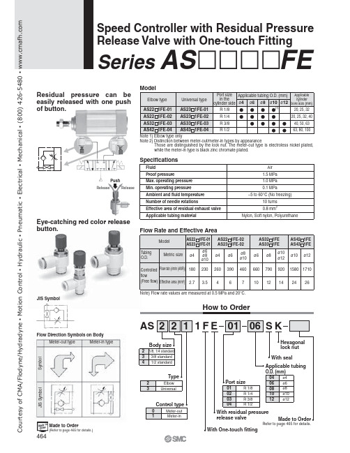
JIS SymbolFlow Direction Symbols on Body1ReleaseMade to Order(Refer to page 465 for details.)Refer to page 465 for details.Speed Controller with Residual Pressure Release Valve with One-touch FittingSeries AS FEResidual pressure can be easily released with one push of button.Eye-catching red color release button.How to OrderS y m b o lMeter-out typeMeter-in typeJ I S S y m b o lC o u r t e s y o f C M A /F l o d y n e /H y d r a d y n e ŀ M o t i o n C o n t r o l ŀ H y d r a u l i c ŀ P n e u m a t i c ŀ E l e c t r i c a l ŀ M e c h a n i c a l ŀ (800) 426-5480 ŀ w w w .c m a f h .c o mAS2201FE-01, AS2211FE-01AS2301FE-01, AS2311FE-01AS4201FE, AS4211FE AS4301FE, AS4311FEAS2201FE-02, AS2211FE-02AS2301FE-02, AS2311FE-02AS3201FE, AS3211FE AS3301FE, AS3311FELubricant: VaselineX12Ex.) AS2201FE-01-04SK-X12Throttle Valve (Without Check Valve)X214Ex.) AS2201FE-01-04SK-X214Ex.) AS2201FE-01-04SK-X21Note) Throttle valve is only compatible with the part no. of the meter-out type.F l o w r a t e (l /m i n (A N R ))E f f e c t i v e a r e a (m m 2)Inlet pressure: 0.5 MPaNumber of needle rotations F l o w r a t e (l /m i n (A N R ))E f f e c t i v e a r e a (m m 2)Inlet pressure: 0.5 MPaNumber of needle rotationsF l o w r a t e (l /m i n (A N R ))E f f e c t i v e a r e a (m m 2)Inlet pressure: 0.5 MPaNumber of needle rotationsF l o w r a t e (l /m i n (A N R ))E f f e c t i v e a r e a (m m 2)Inlet pressure: 0.5 MPaNumber of needle rotationsGrease-free (Seal: Fluorine Coating) +Throttle Valve (Without Check Valve)X21Needle Valve/Flow CharacteristicsBe sure to read before handling.Refer to front matters 58 and 59 for Safety Instructions and pages 412 to 414 for Flow Control Equipment Precautions.CautionMade to OrderNote 1)Not particle-freeNote 2)Throttle valve is only compatible with the part no. of the meter-out type.C o u r t e s y o f C M A /F l o d y n e /H y d r a d y n e ŀ M o t i o n C o n t r o l ŀ H y d r a u l i c ŀ P n e u m a t i c ŀ E l e c t r i c a l ŀ M e c h a n i c a l ŀ (800) 426-5480 ŀ w w w .cElbow type Meter-out typeUniversal type Meter-out typeMeter-in typeMeter-in typeNote 2) Meter-in type is black zinc chromate plated.Construction(2)C o u r t e s y o f C M A /F l o d y n e /H y d r a d y n e ŀ M o t i o n C o n t r o l ŀ H y d r a u l i c ŀ P n e u m a t i c ŀ E l e c t r i c a l ŀ M e c h a n i c a l ŀ (800) 426-5480 ŀ w w w .cElbow typeUniversal type(Hexagon widthacross flats)(Hexagon widthacross flats)Applicable tubing O.D. ødDimensionsNote 2)Reference dimensions of R thread after installation.Note 2)Reference dimensions of R thread after installation.DimensionsC o u r t e s y o f C M A /F l o d y n e /H y d r a d y n e ŀ M o t i o n C o n t r o l ŀ H y d r a u l i c ŀ P n e u m a t i c ŀ E l e c t r i c a l ŀ M e c h a n i c a l ŀ (800) 426-5480 ŀ w w w .c。
高压调压阀使用说明

高压调压阀使用说明高压调压阀(HighPressureRegulator,HPR)是一种可控制系统中的压力的重要仪器控件。
它使系统中的压力能够被精确控制,达到特定的设定值,以满足工作要求。
高压调压阀的原理是将机械式的压力变换器和电子式的压力变换器相结合,其中机械式的变换器由调节阀提供阀口压力,而电子式变换器由电磁控制阀、电容控制阀等控制元件控制阀口压力。
通过控制阀口压力,实现对高压系统中压力的控制。
高压调压阀的应用非常广泛,主要用于高压气体或液体系统的控制,可以调节系统的压力以满足特定的工作要求,以达到节能减排的目的。
使用高压调压阀时,应正确配置、正确安装,确保阀门的正常工作。
一般来说,应注意以下几点:1.装高压调压阀时,应充分考虑管路的位置,以及压力的最大可能值,确保系统的安全运行。
2.压调压阀的法兰安装应符合管路位置和管路直径要求,确保管路通畅。
3.装时,必须使用专用螺栓和垫片,以防止调压阀在运行中弄松或过度拧紧。
4.压调压阀的安装位置有可能受到外力的影响,应注意安装结构的可行性和安全性。
5.保安装完毕后,高压调压阀正常自动调整压力。
使用高压调压阀时,应妥善操作,以避免损坏阀门或造成系统事故。
1. 使用高压调压阀时,必须注意系统中的安全压力控制,不要过度调整压力。
2.压阀可以使系统得到精确控制,减少压力突变带来的损坏,从而获取稳定的压力。
3.动调整调压阀前,应先检查系统的压力是否超出了设定值,以免造成损坏。
4.期维护高压调压阀,检查阀门、阀座、密封圈等是否损坏,保证阀门正常工作。
5.压调压阀应尽可能安装在低温,防止阀门受到温度变化的影响,导致调节出现问题。
高压调压阀以其准确性和可靠性而获得了许多的应用,在系统压力的控制方面发挥着重要的作用,减少了系统运行中可能引起的危害。
因此,高压调压阀的选择、安装和使用都需要特别的注意,以确保系统的安全性及正常运行。
阀门技术性能说明(优.选)
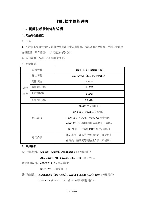
阀门技术性能说明一、闸阀技术性能详细说明1、用途和性能规范1)用途a、本产品主要用于气体、液体介质管路上作启闭装置,接通或截断介质流,不适用于调节介质流量。
具有流阻小,启闭速度快等优点。
b、适用范围:石油、石化等相关工业。
2)性能规范2、采用标准设计制造标准:API 600、API602、ASME B16.34(美标阀门)GB/T 12234、GB/T 12224、JB/T 7746(国标阀门)结构长度标准:ASME B16.10(美标阀门)GB/T 12221(国标阀门)法兰端标准:ASME B16.5(DN≤600)、ASME B16.47B(DN≥650)(美标阀门)GB/T 9113或HG/T 20592或JB 79等(国标阀门)螺纹端标准:ASME B1.20.1(美标阀门)GB/T 12716(国标阀门)承插焊端标准:ASME B16.11(美标阀门)JB/T 1751(国标阀门)对焊端标准:ASME B16.25(美标阀门)GB/T 12224(国标阀门)检验试验标准:API 598(美标阀门);JB/T 9092、GB/T 13927(国标阀门)3、闸阀外型结构图锻钢闸阀外型图锻钢闸阀结构图DN15~50 CL150~900(PN1.0~16.0 Mpa)铸钢闸阀外型图铸钢闸阀结构图DN50~800 CL150~900(PN1.0~16.0 Mpa)4、结构特点1)、闸阀结构为刚性(锻钢闸阀)或弹性(铸钢闸阀)楔式单闸板,法兰连接阀盖,明杆(升降杆)带支架结构。
2)、符合国内外先进标准的要求,密封可靠、性能优良、造型美观。
美标闸阀设计制造符合API 602、API600标准,国标闸阀设计制造符合JB/T 7746、GB/T 12234标准。
3)、全通径设计,流通性能好,流体阻力小,密封面受介质的冲刷和侵蚀小。
4)、介质流向不受限制,不扰流、不降低压力。
5)、阀体为直通式铸造结构,形体简单,结构长度短,制造工艺性好,适用范围广。
高速透气阀使用说明书
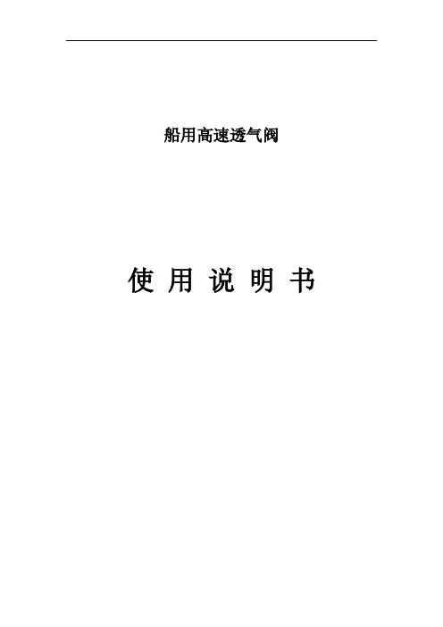
船用高速透气阀使用说明书目录前言———————(1)1高速透气阀的结构和主要技术参数———————(2)2运输和安装———————(6)3高速透气阀的工作原理———————(8)4基本功能与操作指南———————(9)5高速透气阀的维护保养———————(16)6常见故障的判别和维修———————(22)7售后服务———————(23)8用户信息反馈———————(24)前言高速透气阀又称高速排放压力/真空阀,它是真空阀、压力阀和高速排放装置三位一体的重力式自动控制压力大小的货油舱透气装置。
其功能在货油装载过程中可使大量的蒸发气混合气体排出货油舱。
当阀开启后,出口处的排气速度在任何流量下都大于30m/s,在卸载过程中可使大量的空气吸入货油舱,以平衡油舱压力;在驱除油气的过程中可使油气经本阀门排放出货油舱。
在正常航行中,由于温度变化,可使少量油气自动排出货油舱或使少量空气进入货油舱。
当油船甲板上出现火情时,本高速透气阀可阻止外界火苗进入受保护的舱室。
因此,高速透气阀是油船、化学品船必备的透气装置。
本阀门的结构设计制造及试验按GB/T19699-2005 ISO15364:2000《船舶与海上技术货油舱压力/真空阀》标准,IMO MSC/Circ.677《阻止火焰进入油船液货舱的装置设计、试验及安装的修订标准》,CB/T604-93《油舱空气管防火网》。
本公司生产的高速透气阀在达到排放压力时,其升程大,使用过程中无颤振,无撞击,其性能安全可靠。
本产品型式试验的试验项目有静水压力试验、气密试验、压力阀开启压力和关闭压力试验、真空阀开启压力和关闭压力试验、耐腐蚀试验、冰冻试验、压力阀流动性能试验、真空阀流动性能试验、金属防火网后燃试验、高速透气口后燃试验及耐久燃烧试验、驱气帽后燃试验。
产品使用前请仔细阅读本使用说明书。
使用本产品时应严格遵守警告语及注意事项,否则可能会引起危害船舶及人身安全等不良后果。
本使用说明书阅读后请妥然保管以备查阅。
RotoRK 型号为IQ或IQM阀门说明书
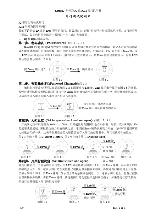
如图1-3按Left 键 按+或-键:修改密码值 按Enter 键:确认被修改的密码按Enter 键:确认密码 按Down 键:进入 按Down 键 按Down 键 按Left 键键:阀门调试说明书IQ 型号为两位式阀门IQM 型号为调节型阀门我们不论调试IQ 还是IQM 型号的阀门,都必须首先将阀门切换开关切换到就地位置,方可进行阀门调试,否则也只简单地看一看阀门一些(此)参数而已。
二、IQ 和IQM 调试说明:第一步:密码确认(PS:Password )如图1-1、1-2RotoRK 的IQ 和IQM 两种型号的阀门,在开始调时都需要进行密码确认,如果不进行密码确认就不能够修改阀门的内部参数,阀门也就不能实现各种功能。
在调试阀门时,首先按下Down 键,阀门LED 显示器会显示如图1-1画面,这时密码还没有被确认,按Enter 键密码就被确认,这时LED 显示器会显示如图1-2画面。
第二步:密码修改(PC:Password Changed)如图1-3如果你想更改密码可以在显示如图1-2的画面时按Left 键,LED 显示器会显示如图1-3的画面,按+和-键可以修改密码,最后只要按一次Enter 键时被修改后的密码会闪烁一次,表示修改密码成功。
以后再次进入就必须输入此密码方可进入该系统。
第三步:力矩设定(Set torque value closed and open )如图1-5、1-6开关阀力矩可设范围为40%——100%,如果越出此范围阀门会自动报警,每按一次+或-键时1%的递增或者递减。
所被设定的力矩值确认之后,可以按Enter 键确认所设力矩值,这时可以看到所设力矩值会闪烁一次,这表明你所设定的力矩值已被存入阀门的存储器中,阀门已认可你的设定。
图1-5中的字符(TC:Torque Closed );图1-6中的字符(TO:Torque Open )第四步:开关行程设定(Set limit closed and open )将阀门移动到一个合适的全关位置,当LED 显示器显示如图1-7时,按Enter 键时,显示器上的两条横线会闪烁一次,这表示阀门的全关位置已被执行器所接收并确认。
Eaton ASV60高级纵轴阀服务手册说明书
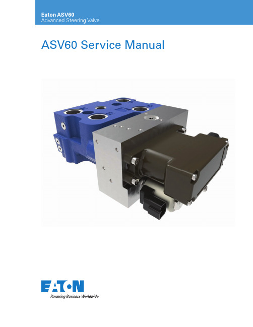
ASV60 Service ManualTable of contentsASV60 SERVICE MANUAL June 2019 2Introduction . . . . . . . . . . . . . . . . . . . . . . . . . . . . . . . . . . . . . . . . . . . . . . . . . . . . . . . . . . . . . . . . . . .3Document scope . . . . . . . . . . . . . . . . . . . . . . . . . . . . . . . . . . . . . . . . . . . . . . . . . . . . . . . . . . . . .3Safety considerations . . . . . . . . . . . . . . . . . . . . . . . . . . . . . . . . . . . . . . . . . . . . . . . . . . . . . . . . . . . . . . .3General Information . . . . . . . . . . . . . . . . . . . . . . . . . . . . . . . . . . . . . . . . . . . . . . . . . . . . . . . . . . . .3ASV60 valve operation . . . . . . . . . . . . . . . . . . . . . . . . . . . . . . . . . . . . . . . . . . . . . . . . . . . . . . . . . . . . . .3ASV60 Technical specifications . . . . . . . . . . . . . . . . . . . . . . . . . . . . . . . . . . . . . . . . . . . . . . . . . . . . . . . .4ASV60 Valve assembly and component details . . . . . . . . . . . . . . . . . . . . . . . . . . . . . . . . . . . . . .5Spare parts list and Seal kits . . . . . . . . . . . . . . . . . . . . . . . . . . . . . . . . . . . . . . . . . . . . . . . . . . . . .6SCU or Manifold interface - seal kit . . . . . . . . . . . . . . . . . . . . . . . . . . . . . . . . . . . . . . . . . . . . . . . .7Assembly torque specification . . . . . . . . . . . . . . . . . . . . . . . . . . . . . . . . . . . . . . . . . . . . . . . . . . . .83ASV60 SERVICE MANUAL June 2019 Document scopeThis document provides information for servicing ASV60 valves .• Serviceable parts and spare part list •Assembly torque informationSafety considerationsB efore commencing, ensure that the individualperforming the service has proper training and tools for servicing a ASV60 valve .If the valve is mounted below the tank, service oil may leak when any valve is removed .Additional resources: ASV60 User Manual1. Load reaction switching valve (Optional)2. Cylinder port relief valves3. Isolation valve4. Main stage valve5. Mode select valve (Externally powered)6. Pressure reducing valve (Pilots)7. Load sense shuttle valve8. Proportional pressure reducing valves 9. Redundant LVDT spool sensorIntroductionASV60 advanced steering valvePrincipal of operation:The ASV60 is a two-stage proportional valve . The mainvalve is a closed-center, load sense valve which is designed to supply proportional flow to the steering application with high accuracy and ~zero hysteresis . An isolation spool is used which “isolates” the main-stage spool from the work ports . It is normally closed and piloted (to open) by an on/off solenoid valve . During normal operation, the isolation valve must remain actuated to ensure flow can be delivered to and from the work ports . By removing power to the “mode select valve” the isolation valve can be closed at any timeallowing for the isolation of the main-stage spool from the steering cylinder(s) .ASV60 will communicate with any CAN-enabled controller . The standard interface with the vehicle controller is CAN J1939 . The inclusion of CANbus communication and an onboard spool position sensor yields high precision flow control .4ASV60 SERVICE MANUAL June 2019 ASV60 T echnical specifications:Pressures Rated inlet (P Port) 210 Bar (3045psi)Max work ports (L & R Ports) 250 Bar (3625 psi)Max tank (T Port)21 Bar (305 psi)Flow @ 14bar control pressureASV60X130 lpm (7.9 gpm)ASV60X245 lpm (11.9 gpm)ASV60X360 lpm (15.9 gpm)ElectricalInput voltage12VDC (9-16 VDC)24VDC (18-32 VDC)Power/Current consumptionPilot Valve – 25 W Max Mode select valve Solenoid – 15.8 W Max CAN InterfaceJ1939, 2.0BRandom vibration***Standard IEC 60068-2-64:2008FiltrationISO 440618/16/13Pilot valve filter screen125µmActuation command optionsPilot valve flow command CAN / PWM Isolation valve commandPWMControl modesOpen loop command+/- 100% current Closed loop command+/- 100% flowElectrical interface connectorsPilot valve connectorDeutsch connector: DT14-6P Solenoid valve connectorDeutsch connector: DT04-2PElectromagnetic protectionEC Directive EMC Directive 2014/30/ECWeightStandard version (ASV60 only)8 kg (17.6 lb)Temperature*Standard oil (operating)*-30 to 90˚C (14 to 194˚F)Ambient (operating)-30 to 95˚C (-22 to 203˚F)Ambient short term (operating)-30 to 105˚C (-22 to 221˚F)* I t is recommended that the ASV60 valve is not be subjected to a thermal difference of greater than 50˚F (28˚C).Electrical environmental**Ingress protection ISO 20653: IP6k6/IPX9K Thermal cycling -30˚C to 95˚C (-22 to 203˚ F) for 1200 cyclesMechanical shockHalf-sine pulse: 40 G / 6 ms (IEC 60068-2-27 Ea)** A dditional Electrical Environmental tests were performed. Contact Eaton for additional details, if desired.Port typesP, L, R, T3/4”- 16 UNF (SAE-08), G 1/2, M18LS7/16”-20 UNF (SAE-04), G 1/4, M12Dynamic performanceTypical step responseMax: 200 msec (Neutral to 90% of main spool position)ViscosityRecommended 12-85 cSt Minimum 7 cSt Maximum812 cStASV60 Valve assembly and component detailsPort options:Main ports SAE Metric BSPPorts: Pressure, Tank, Left & Right3/4-16 UNF O-RING PORTS (SAE-8)M18x1.5 -6H METRIC O-RING PORTS G1/2 STRAIGHT THREAD PORTSLS Port: 7/16-20 UNF LOAD SENSING O-RINGPORT (SAE -4)M12 X 1.5-6H LOAD SENSING METRICO-RING PORTG 1/4 (BSP) LOAD SENSING STRAIGHTTHREAD PORT5 ASV60 SERVICE MANUAL June 2019 6ASV60 SERVICE MANUAL June 2019 Spare parts listSeal kitsSpare parts•Seal kit• ASV60 Valve & cover plate Interface………………………………… . . . . . . . . . . . . . . . . . . . .9901403-000• SCU or Back-up manifold Interface……………………………………… . . . . . . . . . . . . . . .9901404-000•Mounting cap screw• Size: M10 x 1 .0 .……………………………………… . . . .……………… . . . . . . . . . . . . . . . . . . . . . . . . . .14621-004•Size: M5 x .8 .……………………………………… . . . .……………… . . . . . . . . . . . . . . . . . . . . . . . . . . . . . . . . . . .473723otee:N Valve require air bleeding (actuate the main spool left and right at 0 .02 to 0 .05 Hz for 5 minutes or until no air remains in the system) after replacement of any seals .ASV60 Valve & cover plate – seal kit – 9901403-000Item number Part number Material/ Size Durometer Quantity 116015-7Nitrile (Buna N) / -019702ASV60 Valve & cover plate interface Seal kitSCU or Manifold interface - seal kitSCU Or manifold interface – seal kit – 9901404-000Item number Part number Material/ Size Durometer Quantity116015-18-90Nitrile (Buna N) / -118904216003-11-90Nitrile (Buna N) / -1139017ASV60 SERVICE MANUAL June 2019 EatonHydraulics Group USA 14615 Lone Oak Road Eden Prairie, MN 55344USATel: 952-937-9800Fax: 952-294-7722www .eaton .com/hydraulicsEatonHydraulics Group Europe Route de la Longeraie 71110 Morges SwitzerlandTel: +41 (0) 21 811 4600Fax: +41 (0) 21 811 4601EatonHydraulics Group Asia Pacific Eaton BuildingNo .7 Lane 280 Linhong Road Changning District, Shanghai 200335 ChinaTel: (+86 21) 5200 0099Fax: (+86 21) 2230 7240Assembly torque specificationCap screw size: M5 X .8Torque to 8-1Eaton is a registered trademark. All other trademarks are property of their respective owners.Eaton1000 Eaton Boulevard Cleveland, OH 44122United States Eaton .com© 2019 EatonAll Rights Reserved Printed in USADocument No . E-VLMB-RR001-E June 2019。
高真空 L 型阀 XLD 系列 使用说明书

文件No.XL-OMY0002高真空L型阀XLD系列安全注意事项‐‐‐‐‐‐‐‐‐‐‐‐‐‐‐‐‐‐‐‐‐‐‐‐‐ 21.使用注意事项1 ‐‐‐‐‐‐‐‐‐‐‐‐‐‐‐‐‐‐‐‐‐‐‐‐‐ 4 (配管 , 气源)2. 使用注意事项2 ‐‐‐‐‐‐‐‐‐‐‐‐‐‐‐‐‐‐‐‐‐‐‐‐‐ 5 (设计注意事项 , 选型 , 安装 , 配管 , 维修保养)3.使用注意事项3 ‐‐‐‐‐‐‐‐‐‐‐‐‐‐‐‐‐‐‐‐‐‐‐‐‐ 7 (维修零部件)4.产品规格‐‐‐‐‐‐‐‐‐‐‐‐‐‐‐‐‐‐‐‐‐‐‐‐‐ 9 5.构造‐‐‐‐‐‐‐‐‐‐‐‐‐‐‐‐‐‐‐‐‐‐‐‐‐ 11 6.操作方法‐‐‐‐‐‐‐‐‐‐‐‐‐‐‐‐‐‐‐‐‐‐‐‐‐12 7.外形尺寸‐‐‐‐‐‐‐‐‐‐‐‐‐‐‐‐‐‐‐‐‐‐‐‐‐ 13 8.型式表示方法‐‐‐‐‐‐‐‐‐‐‐‐‐‐‐‐‐‐‐‐‐‐‐‐‐ 14 9.保证期限和保证范围‐‐‐‐‐‐‐‐‐‐‐‐‐‐‐‐‐‐‐‐‐‐‐‐‐ 15 10.零部件更换要领‐‐‐‐‐‐‐‐‐‐‐‐‐‐‐‐‐‐‐‐‐‐‐‐‐16安全注意事项此处所示的注意事项是为了确保您能安全正确地使用本产品,预先防止对您和他人造成危害和伤害而制定的。
这些注意事项,按照危害和伤害的大小及紧急程度分为“注意”“警告”“危险”三个等级。
无论哪个等级都是与安全相关的重要内容,所以除了遵守国际规格(ISO/IEC)、日本工业规格(JIS)*1)以及其他安全法规*2)外,这些内容也请务必遵守。*1) ISO 4414: Pneumatic fluid power -- General rules relating to systemsISO 4413: Hydraulic fluid power -- General rules relating to systemsIEC 60204-1: Safety of machinery -- Electrical equipment of machines (Part 1: General requirements)ISO 10218: Manipulating industrial robots-SafetyJIS B 8370: 空气压系统通则JIS B 8361: 油压系统通则JIS B 9960-1: 机械类的安全性-机械的电气装置(第1部:一般要求事項)JIS B 8433: 产业用操作机器人-安全性等*2) 劳动安全卫生法等注意误操作时,有人员受伤的风险,以及物品损坏的风险。警告误操作时,有人员受到重大伤害甚至死亡的风险。
高级孔板阀的操作规程完整

高级孔板阀的操作规程完整GC/ZK-1: 高级孔板阀的操作规程1. 更换孔板1.1 取出孔板的操作1.1.1 打开上下腔之间的平衡阀;1.1.2 全开滑阀;1.1.3 将孔板从下阀腔提到上阀腔;1.1.4 关闭滑阀;1.1.5 关闭平衡阀;1.1.6 开放空阀完全排除上阀腔中气体;1.1.7 打开上阀腔顶丝,取出顶板、压板;1.1.8 转动上阀腔导板提升轴,将孔板提出。
1.1.9 注重事项●全开滑阀前必须先平衡上、下阀腔压力,再转动滑阀传动杆,顺时针转动为开,反时针转动为关;开关滑阀时,一定要让指针指示到位。
并细致观察滑阀关闭严密情况,若有泄漏加入密封脂;●反时针转动孔板导板转动杆为提升孔板导板,在转动下滑腔传动杆时,看到上阀腔传动杆同时转动时,应换为转动上阀腔传动杆,直到转不动为止;●严格执行操作规程,操作平稳,用力适度。
1.2 安装孔板的操作1.2.1 转动上阀体导板提升轴,将孔板端正、平齐地放入上阀腔;1.2.2 将压盖污物清理干净后盖好压板、顶板,上好顶丝;1.2.3 打开平衡阀,平衡上、下阀腔压力;1.2.4 转动滑阀操作轴,打开滑阀;1.2.5 转动下阀体导板提升轴,将孔板摇至下阀腔工作位置;1.2.6 关闭滑阀;1.2.7 旋转密封脂盒盖,缓慢注入密封脂;1.2.8 关闭平衡阀;1.2.9 打开放空阀,排除上阀腔气体;1.2.10 关闭放空阀;1.2.11 检查各密封处,若有泄漏应立即处理。
1.2.12 注意事项●孔板密封四周、导板齿条上涂抹适量润滑脂;●压盖、密封垫应清洗干净不能沾泥沙,平整放好密封垫后,装压盖对称上紧顶丝;●开放空阀放空时,若气流声很快消失,则说明操作全部到位,否则应检查滑阀与平衡阀是否关到位;●严格操作步骤,并做到操作平稳,用力适度。
●注意孔板安装方向。
2. 清洗检查孔板2.1 将要清洗检查的计量支路切换至备用状态;2.2 在流量计算机上作适当操作;2.3 取出并检查清洗孔板;2.4 外观检查:上下游表面,园筒形部分边缘不应有沉积污垢、坑浊及明显缺陷;同时检查孔板上的橡胶密封脂,应无断裂、坑槽、严重腐蚀、变形,否则更换;2.5 孔径测量:用0.02级游标卡尺在园柱部4个大致等角度位置上测量,其结果的算术平均值与孔板上刻印的孔径值、计算K值使用的孔径值三者应一致;2.6 变形检查:用适当长度的样板直尺轻靠孔板上、下游后,转动样板直尺,用塞尺测出沿孔板直径方向的最大缝隙宽度hA。
高加快关阀使用说明书
电液控制快速关断阀说明书KGF20/40-F-T-A沈阳东北电力调节技术有限公司目录1、概述…‥…‥…‥…‥…‥…‥…‥…‥…‥‥…‥……‥…‥…‥22、结构形式与工作原理…‥…‥…‥…‥…‥…‥…‥…‥…‥…‥…‥33、安装方法及注意事项…‥…‥…‥…‥…‥…‥‥……‥…‥…‥…‥64、操作规程...‥...‥...‥...‥...‥...‥...‥...‥...‥‥...‥...‥......‥ (7)5、常见故障处理...‥...‥...‥...‥...‥...‥...‥...‥‥...‥...‥...‥ (8)6、电气原理图‥…‥…‥…‥…‥…‥…‥…‥…‥…‥……‥………‥117、用户接线图…‥…‥…‥…‥…‥…‥…‥…‥…‥…‥…‥…‥…‥128、控制箱结构图...‥...‥...‥...‥...‥...‥...‥...‥...‥...‥...‥‥ (13)9、执行器装配图…‥…‥…‥…‥…‥…‥…‥…‥…‥‥…‥……‥‥1410、液压原理图‥‥‥‥...‥...‥...‥...‥...‥...‥...‥‥...‥......‥ (15)11、蓄能器充气工具使用方法说明‥…‥…‥…‥…‥…‥……‥…‥16一、概述:本快速关闭阀产品是专门为热电厂汽轮机组设计的安全设备,可以有效防止抽汽管道蒸汽倒流引起的汽轮机超速事故。
本产品阀门采用进口三偏心金属密封蝶阀,执行机构采用高度集成电液执行器。
整个设备具有结构紧凑、体积小、重量轻、外形美观的特点,本设备密封效果好,达到零泄漏,使用寿命长,关闭速度快,控制灵敏可靠,是保证机组安全运行的最佳选择。
本阀门参数:1、阀门通径:■ DN200 □ DN250 □ DN300 □ DN350 □ DN400 □ DN500 □ DN6002、适用介质:蒸汽3、阀门适用温度:□ 350℃■ 400℃□ 460℃4、阀门额定压力:□ 1.0MPa □1.6MPa □2.5MPa ■4.0MPa □6.4MPa □100MPa5、阀门材料:■碳钢20 □不锈钢1Cr18Ni9Ti6、阀门转角:0~90°7、蓄能器充气压力:5MPa8、阀门快速关闭时间:阀门关闭90%时,关闭时间小于0.5秒;阀门全部关闭时,关闭时间小于0.8秒。
阀门型号及其含义说明
阀门型号及含义说明一、通用阀门:所有阀门型号都有下面七个单元组成:1 2 3 4 5 ——6 7通常应表示阀门类型、驱动方式、连接形式、结构特点、密封面材料、公称压力、阀体材料等。
以下图为例:1、阀门类型代号:即:Z 闸阀J截止阀L节流阀H止回阀和底阀Q球阀X旋塞阀D蝶阀A安全阀S蒸汽疏水阀Y减压阀G隔膜阀注明:当阀门还具有其它功能作用或带有其它特异结构时,在阀门类型代号前再加注一个汉语拼音字母(1)阀门类型代号前加“D”为低温阀门(低于-40℃);代号前加“B”为保温的阀门(带加热套);防火型F;缓闭型H。
(2)截止阀类型代号前加“W”,表示波纹管密封阀门。
(3)闸阀类型代号前加“P”表示用于排渣系统阀门,加“X”或“K”为排渣用泥浆阀。
(4)在地下水用闸阀类型代号前加“S”表示竖式安装,加“W”表示卧式安装。
(5)在地下水用闸阀类型代号前加“D1”、“D2”表示短系列,加“Q”表示球蝶阀,加“S”表示用于地下管网蝶阀。
2、传动方式代号:即:0电磁动1电磁-液动2电-液动3蜗轮(蜗杆)4正齿轮5锥齿轮6气动7液动8气-液动9电动若为手动则省略注明:对于齿轮、手柄、扳手等直接传动或自动阀门(安全阀、减压阀、疏水阀、手轮直接连接阀杆操作结构形式的阀门)本代号省略,不表示;对于气动或液动机构操作的阀门,常开式用6K、7K表示,常闭式用6B、7B表示,气动带手动用6S表示。
防爆电动装置的阀门用9B表示,户外耐热式用9R表示。
3、连接方式代号:即:1内螺纹2外螺纹4法兰式6焊接式7对夹式8卡箍9卡套4、结构形式代号阀门结构形式用1位阿拉伯数字表示,如下:(一)闸阀结构形式代号:即:0楔式弹性闸板1楔式单闸板2楔式双闸板3平行式单闸板4平行式双闸板(二)截止阀、截流阀结构形式代号:即:1直通式4角式5直流式(三)止回阀结构形式代号:代号 1 2 3 4 5 6 7 8 9结构型式升降式阀瓣旋启式阀瓣升降式阀瓣蝶式直通流道立式结构角式结构单瓣结构多瓣结构双瓣结构直流式节流再循环式即:1直通式2升降立式3升降角式6旋启单瓣式(四)安全阀结构形式代号:(五)调节阀结构形式代号:(六)球阀结构形式代号:即:1浮球直通式7固定直通式(七)给水分配阀、减压阀、旋塞阀、蝶阀、输水阀、隔膜阀结构形式代号:注明:结构形式如为杠杆式安全阀,在结构形式代号前加“G”,1代表单杆微启,2代表单杆全启,3代表双杆微启,4代表双杆全启.5、密封面材质代号:(用汉语拼音字母表示)注:当阀座与阀瓣材质不同时,用底硬度材料代号表示(隔膜阀除外)即:H合金钢Y硬质合金F氟塑料T铜合金P渗硼钢X橡胶N尼龙塑料B锡基轴承合金(巴氏合金)Q衬铅J衬胶C、P 陶瓷、渗硼钢W本体材质( 碳化钨硬质合金)6、公称压力代号:公称压力数值用阿拉伯数字直接表示,并用短线与前五个单元分开。
KOSO SS-CE-720E-B 高性能蝶阀 说明书

概要 GENERAL720E高性能蝶阀的阀板与阀座具有独特的结构设计,因此具有优良的切断性能和耐久性能,是一种用途广泛的调节阀。
This series is high performance butterfly valve of high durability, high seating performance. It has several diffe-rent seal ring construction suitable to various service appli-cations.标准规格 STANDARD SPECIFICATIONS本体部BODY型号Series 720E*①公称通径Body size 3"~24"(80A~600A即DN80~DN600)阀板形状Disc form 偏心型部分球面阀板Eccentric type segmental ball disc阀内件材质阀内件处理Trim materialsTrim treatment标准材质组合及使用温度·压力范围,请参见表1。
See Table1 for hardening treatment and operating pressure-temperature.公称压力Body ratings L Class Body/L 级阀体 : JIS 10K/ANSI Class 150/PN 16*②M Class Body/M级阀体: JIS 20K/ANSI Class 300/PN 40*②连接方式Body connections 法兰型 ( RF、凹凸式) Flanged(RF、MFM)尺寸Dimension 请参见第34~53页。
See pages 34~53.阀体及上阀盖材质Body & BonnetMaterialSCPH2/WCB, SCS13A/CF8, SCS14A /CF8M , and other alloy steels.各种材质的使用温度·压力范围,请参见表1和表2。
曼斯特克高性能电子阀门说明书
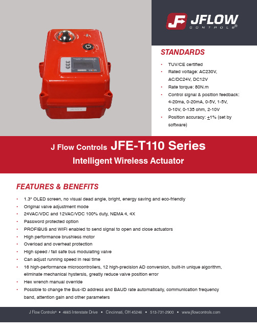
FEATURES & BENEFITS• 1.3" OLED screen, no visual dead angle, bright, energy saving and eco-friendly • Original valve adjustment mode• 24VAC/VDC and 12VAC/VDC 100% duty, NEMA 4, 4X • Password protected option• PROFIBUS and WIFI enabled to send signal to open and close actuators • High performance brushless motor • Overload and overheat protection• High speed / fail safe bus modulating valve • Can adjust running speed in real time• 16 high-performance microcontrollers, 12 high-precision AD conversion, built-in unique algorithm, eliminate mechanical hystersis, greatly reduce valve position error • Hex wrench manual override•Possible to change the Bus-ID address and BAUD rate automatically, communication frequency band, attention gain and other parametersJ Flow ControlsJFE-T110 SeriesIntelligent Wireless ActuatorJ Flow Controls ® • 4665 Interstate Drive • Cincinnati, OH 45246 • 513-731-2900 • ®TECHNICAL DATAElectrical dataRated voltage AC230V50/60HZAC/DC24VRated voltage range AC95-265V/DC100-300VAC18-26V/DC22-32VPower consumption ****************@keep ****************@keep Peak current 0.26A@5ms@AC230V 0.52A@KT@5ms@AC230V 4.5A@5ms@DC24V0.52A@5ms@AC110V 1.10A@KT@5ms@AC110V10A@KT@5ms@DC24VFuse2A5A@KT15AConnecting cable Connector: 9P-5.08-500V x (0.5-1.5)mm 2, / 10P-(0.3-0.5)mm 2Functional dataRated torque 80Nm@rated voltage Angle of rotation90+2°Max angle of rotation 330+5°Manual operation Matching hexagon wrench, using at power cut Running time About 10sOperating modeS3-70% (loading <85% rated torque)Sound power levelMax 65dB(A)Position indicatorMechanical and screenWorking conditionsElectricity safety level I Type (ground protection) III Type (ground protectionInflaming retardinglevel1.6mmHB/UL94 test methodEnclosureIP67 As per EN60529/GB4208-2008 (all directions)F type can add dehumidifying heater Insulation resistance 100M Ω / 1500VDC 100M Ω / 500VDC Withstand voltage 1500VAC@1Min500VAC@1MinMedium temperature<80° can install with actuator directly>80° need to install bracket or heat radiation stand Working environmentIndoor or outdoor; if exposed to the rain or sunshineNeed to install protective device for the actuatorExplosion-proof level ! Not explosion proof products. Do not use in flammable & explosive environments Ambient temperature 14°F to 140°F (ABS); Custom options -4°F to 140°F Non-operation temp <-40°F or >176°FAmbient humidity 5-95% RH non-condensing Shock resistance <300m/s 2Vibration10 to 55 Hz, 1.5 mm double amplitudeInstallation notes 360° any angle. The need for manual operation or the wiring space Maintenance Free maintenance Certification CEDimensions/weightDimensionsSee dimensionsConnection standard ISO5211 F05, F07Output axis specification Female octagonal Hole deepness <0.79" (Female octagonal)WeightABS material 4.9 lbsDIMENSIONS4.8"4.4"4.5"2.6"2.6"45°Ø2.8"Ø1.97"M8X4 Thread 0.39M6X4 Thread 0.24M14x1.5waterproof lock nut0.04"6.5"PARTS5423191187106No Parts Name Materials No Parts Name Materials 1Actuator ABS 7Wrench fixed ABS2Indicator TransparentAS 8Hexagon wrench Tool steel 3Screwx43049Waterproof cableconnectorNiLon 4Manual shaft 30410Seal part betweenup and down cover NBR 5Oil sealNBR 11Terminal coverABS6LabelPVCWIRING DIAGRAMS4-20mA / 0-20mA0-5V/1-5V / 0-10V / 2-10VBlack Red Blue Gray White BrownFlowerFigure 1 (7 wiring diagram0.83" heightWIRING DIAGRAMSWIRING DIAGRAMSNotice 1: The range of power is 2W-3W;Notice 2: The range of constant temperatureheating is 77°F +20%JFE-T110 Series Intelligent Wireless ActuatorMOUNTING INSTRUCTIONSNotice1. When assembling with valve, it's suggested to use springwasher with flat washer in order to fasten the screw and nut.2. It's recommended to use 704 silica gel or instant cementinstead of anaerobic adhesive and UV glue.3. Keep the actuator housing away from organic solvents,such as: kerosene, butane, trichloroethane, etc or thehousing may crack.Diagram 1 (with bracket) Diagram 2 (direct mount) Diagram 3 (direct mount)Diagram 1: UPVC plastic ball valve and bracket assemblyDiagram 2: 3 piece stainless steel ball valve assemblyDiagram 3: 3 piece stainless steel 3 way ball valve assemblyINSTALLED V ALVE TECHNICAL REQUIREMENTSValve type Recommend install conditionWafer butterfly valve Actuator rate torque > 2 times valve max torqueFlange butterfly valve Actuator rate torque > 1.7 times valve max torqueMetal ball valve Actuator rate torque > 1.7 times valve max torquePlastic ball valve Actuator rate torque > 1.5 times valve max torque1. If the ball valve is out of operation for a long time, and the torque value of first on or off is the max torque2. When installing a direct mount model valve, the hole deep is < 0.79in. It requires cutting if the output shaft is longer than 0.79in.3. Pay attention to the following items if you install the bracket and coupling by yourself:- The intensity of the bracket should meet the using requirements: the bracket twisting extent <0.0079 in the process of on or off - The parallelism of the bracket < 0.020- When processing the shaft hole at both ends of the coupling, it is necessary to ensure the accuracy and concentrically. The purpose is to make sure the mechanical hysteresis <10°, otherwise it will cause the actuator to work incorrectly.4. The screw should be installed with a spring washer and flat washer and we suggest you daub some glue cement around the screwin case of the screw loosening.5. After installation, the user should switch the valve on and off one time with handle device first. Modifying the valve after makes sureit works well.COMMON FAILURES & PROCESSING METHODSWORKING ENVIRONMENT• Indoor and outdoor are both options• Not explosion-proof products. Do not use in flammable and explosive environments• You need to install protective devices for the actuator if it is exposed to rain or sunshine• Pay attention to the ambient temp• When installing, consider the reserved space for wiring and repairing• When power is one, do not dismantle actuator and valve or connect wiringJ Flow Controls®4665 Interstate DriveCincinnati, OH 45246513-731-2900While the information and specifications contained in this literature are believed to be accurate, they are supplied for informative purposes only and should not be considered certified or a guarantee of satisfactory results. Nothing contained herein is to be construed as a warranty or guarantee, express or implied, regarding any matter with respect to this product. Because J Flow Controls® is continually improving and upgrading its product design, the specifications, dimensions and information contained herein are subject to change without notice.。
高级孔板阀操作

验收过程中应做好记录,包括验收项 目、验收结果、验收人员等信息。
按照相关标准和规范进行验收,包括 外观检查、尺寸测量、性能测试等。
如发现不符合要求的情况,应及时通 知相关人员进行整改,直至符合要求 为止。
常见问题排查及解决方法
孔板阀泄漏
检查密封面是否损坏或异物卡住,及 时清理或更换密封件。
应急处理预案
制定应急处理预案,对可能出现的异常情况 进行及时处理,确保安全生产。
05 性能测试与评估方法论述
性能测试项目介绍
01
密封性能测试
检测孔板阀在关闭状态下的密封性 能,确保无泄漏现象。
耐压性能测试
测试孔板阀在承受一定压力时的稳 定性和安全性。
03
02
操作力矩测试
测量孔板阀开启和关闭所需的操作 力矩,以评估其操作便捷性。
高级孔板阀操作
目录
• 孔板阀基本概念与原理 • 高级孔板阀选型与参数设置 • 安装调试与验收流程规范 • 操作使用技巧与经验分享 • 性能测试与评估方法论述 • 自动化控制技术在高级孔板阀中应用探讨
01 孔板阀基本概念与原理
孔板阀定义及作用
01
孔板阀是一种通过改变流体通道 截面积来调节流量的控制阀门。
阀门关闭后,应检查确认阀门 是否完全关闭,无内漏现象。
维护保养周期建议
01
02
03
04
定期检查
建议每季度对阀门进行一次全 面检查,包括阀门外观、执行
机构、密封件等。
清洗保养
每年至少对阀门进行一次清洗 保养,清除阀门内部的杂质和
污垢,保持阀门清洁。
润滑维护
根据阀门使用频率和环境条件 ,定期对阀门执行机构进行润
高级孔板阀操作维护手册
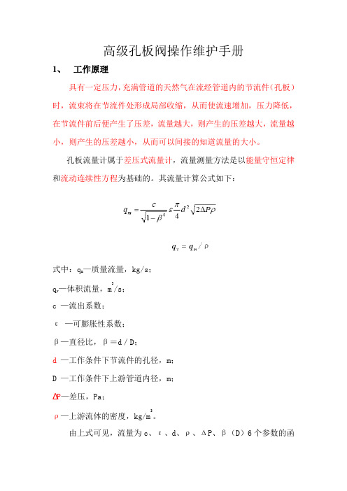
高级孔板阀操作维护手册1、工作原理具有一定压力,充满管道的天然气在流经管道内的节流件(孔板)时,流束将在节流件处形成局部收缩,从而使流速增加,压力降低,在节流件前后便产生了压差,流量越大,则产生的压差越大,流量越小,则产生的压差越小,从而可以间接的知道流量的大小。
孔板流量计属于差压式流量计,流量测量方法是以能量守恒定律和流动连续性方程为基础的。
其流量计算公式如下:式中:q m—质量流量,kg/s;q v—体积流量,m3/s;c —流出系数;ε—可膨胀性系数;β—直径比,β=d/D;d —工作条件下节流件的孔径,m;D —工作条件下上游管道内径,m;∆P—差压,Pa;ρ—上游流体的密度,kg/m3。
由上式可见,流量为c、ε、d、ρ、ΔP、β(D)6个参数的函数,此6个参数可分为实测量[d、ρ、ΔP、β(D)]和统计量(c、ε)两类。
2、设备结构图1-一体化孔板流量计组成图2-一孔板阀结构简图3、操作方法3.1 取出孔板的步骤:3.1.1打开平衡阀,平衡上下腔压力。
3.1.2全开滑阀,用摇柄顺时针方向摇齿轮轴2,摇不动为止。
3.1.3把孔板从下阀腔提至上阀腔,逆时针方向摇齿轮轴3,感觉孔板导板与齿轮轴1咬合时,再逆时针方向摇齿轮轴1至转不动为止。
3.1.4关闭滑板阀,用摇柄逆时针方向摇齿轮轴2,摇不动为止,切断上下腔通道。
3.1.5关闭平衡阀。
3.1.6慢开放空阀,将上阀腔压力放空至零。
3.1.7取下防雨保护罩,拧松螺钉,取掉顶板、压板。
3.1.8逆时针方向继续旋转齿轮轴1,提出孔板。
3.2装入孔板的步骤:3.2.1在孔板密封环四周少许抹一层黄油,将孔板装入导板后放入上阀腔,并将其向下摇至碰到滑板为止。
(孔板开孔扩散方向应朝向介质流动方向)3.2.2顺时针慢摇齿轮轴1至能装压板、顶板位置即可。
3.2.3依次装入密封垫片、压板、顶板,拧紧顶板上的螺钉,盖好防雨保护罩。
3.2.4关闭放空阀。
3.2.5打开平衡阀,平衡上下腔压力。
高级阀式孔板说明书

请用户熟读此说明书简易阀式孔板节流装置(K)JKF—□高级阀式孔板节流装置(K)GKF—□使用说明书川制00000415号成都伦慈仪表有限公司1、用途、性能规范、采用主要标准1.1 用途:本说明书所要叙述的阀式孔板节流装置,分不抗硫及抗硫的高级型、简易型二种,主要用于差压式流量计的信号产生,传输装置。
1.2 性能规范:适用介质:轻质油、净化天然气、水、含硫(H2S+CO2≤8%)天然气、城市煤气,轻烃等。
介质温度:-29~121℃。
(介质温度超过此范围作特殊订货)。
1.3 采用的主要标准:GB/T2624.1—2006 用安装在圆形管道中的差压装置测量满管流体流量第一部分:一般原理和要求GB/T2624.2—2006 用安装在圆形管道中的差压装置测量满管流体流量第二部分:孔板JB/T7252—94 阀孔孔板节流装置JJG640—94 差压式流量计2、作用原理充满管道的流体流经营道内的节流装置,在节流件的前后产生差压,通过测量差压可以衡量流体流过节流装置的流量大小。
3说明:K处:标K为抗硫,不抗硫略。
G处:结构代号,G为高级型,J为简易型。
K处:节流元件孔板代号。
F处:连接形式代号,F为法兰连接,对接略。
16处:公称压力(单位:0.1MPa)。
C处:阀体材料为碳钢,超过PN1.6MPa时C代号略。
5、结构说明及主要处形连接尺寸5.1 高级阀式孔板节流装置(图1、表2、表3)零件名称:1,顶板2,压板3,上阀体4,齿轮轴1,5,注油嘴6,滑阀7,齿轮轴2 8,下阀体9,对焊钢法兰10,对焊钢法兰,11,齿轮轴3 12,平衡阀13,放空阀。
(含导板,孔板,密封圈)特点:1、更换孔板容易,不影响输送介质,无需设置附加管路,占地少,性价比高2、经标定准确度0.5级;注:a. 两端法兰连接尺寸见附件2~3;b. L1=10D20L2=5D20c.计量管道实际通径见附件1。
结构尺寸表表1型号公称通径(mm)外型尺寸(mm)重量≈kg L E F B H H1GKF-16C 50 270 130 190 520 455 100 85GKF-100 KGKF-100 50 360 210 150 550 520 121 130 6580 385 190 245 560 570 161 220 100 420 104 274 550 580 152 295 150 430 216 330 660 720 180 360 200 440 220 390 700 855 217 510 250 500 260 470 760 985 255 768 300 500 255 590 1050 1150 290 1080 350GKF-160 KGKF-160 50 680 190 250 560 660 160 300 6580 700 244 304 650 700 185 500 100 720 246 302 640 720 185 650 150 765 272 372 720 776 199 880 200 900 300 470 850 820 250 1000 250 1000 320 590 1000 900 290 14005.2简易阀式孔板节流装置(图2、表3)图21,阀体2,顶板3,压板4,孔板部件(含孔板导板,孔板,密封圈)5,排污堵头6,对焊钢法兰特点:结构简单,价格低,无孔板提升机构,更换孔板必须停止输送介质。
POWER-SEAL 2 系列手动和自动高性能阀门,ANSI ASME类150和300说明书

POWER-SEAL Series P1S / P1F / P1M / P1H Manual and AutomatedHigh Performance Butterfly Valves ANSI/ASME Class 150 and 300Featuring Actuators and Accessories3FEATURES & BENEFITSFeatures and BenefitsApplication Specific Stem PackingStandard packing is PTFE V-Ring (Type P) for P1S and Graphite (Type G) for Series P1M, P1F and P1H. Other packing options include: PTFE Inverted V-Ring (Type V) or PTFE Double V-Ring (Type D).Live Loaded PackingPower-Seal HPBFVs come standard with Live Loadedpacking. Three sets of Belleville washers are added to each gland stud to maintain a self-adjusting packing load.Internally Cast Travel StopTravel Stop prevents over rotation of the disc in an effort to limit possible seat damage.Seat Retainer DesignSeat retainer is designed so the fasteners do not interfere with the flange gasket sealing surface.Square StemStem design facilitates direct mounting of pneumatic and electric actuators or gear operators through 12”.• Available inventory includes sizes 2”-36”. Larger sizes are available upon request.• Standard body materials are CF8M (316 SST) or WCB. Application specific options include: Alloy 20, Monel, CD3MN, Hastelloy C-276, Inconel 625, Aluminum Bronze, LCB and others.• ANSI/ASME Class 150 and 300 Lug and Wafer • New & improved standard seat material: G2TFE. The new G2TFE seat contains 80% PTFE, 15% glass fiber and 5% molybdenum. The molybdenum is an element found in stainless steels which adds lubricity and longevity to the seat.• Standard seat materials are G2TFE (soft seat), G2TFE/316L SST (Firesafe), and 316L SST (metal seat). Application specific seat materials include: 50/50 STFE, PTFE, TFM ™-1600 and Inconel 625.• Standard Stem Material is 17-4 PH ®. Another option is XM-19.• Soft seat and Firesafe seat designs offer bubble-tight, bi-directional shutoff to full ANSI/ASME Class 150 and 300 standards. Metal seat design offers Class V shutoff.• Blow out proof stem designStandards/CertificationsANSI-B16.34ANSI B16.47ANSI B16.10API-598API-6FA 4th Edition• P1M/P1MC & P1H/P1HC • All Sizes• Class 150 & 300API-607 7th Edition • P1F & P1FC • 3” & Larger• Class 150 & 300API-609ASME-B16.5FCI 70-2 MSS SP-25MSS SP-55MSS SP-67MSS SP-68ISO 5211NACE (from Factory)• MR0175 / MR0103EN 10204-3.1CRNABS Type Approval CSA 3.16-15P1S SeriesSoft seat for bubble-tight shutoff of general purpose applications.*P1F SeriesPrimary G2TFE seat for bubble-tight shutoff backed up by secondary 316L SST fire-safe seat. Secondary fire-safe seat provides Class V shutoff when primary G2TFE seat is compromised in a fire event.*P1M/P1H Series316L SST seat for Class V shutoff of high temperature applications (Inconeldisc optional for extreme temperature).** Refer to Pressure Temperature Chart (pg. 13)5Stem Packing Options for POWER-SEAL High Performance Butterfly ValvesSTEM PACKING OPTIONS & BENEFITSIndustry Leading High Performance Butterfly Valve Packing DesignGraphite (G) (standard for P1F, P1M, P1H Series)Power-Seal High Performance Butterfly valves with Live Loaded Graphite packing for pressure and vacuum applications.PTFE V-Ring (P) (standard for P1S Series)Live Loaded PTFE Chevron packing for pressure and vacuum applications.PTFE Inverted V-Ring (V)Live Loaded Inverted PTFE Chevron packing for pressure and vacuum applications.PTFE Double V-Ring (D)Live Loaded PTFE Chevron packing comestogether with Inverted PTFE Chevron packing for pressure and vacuum applications.Please refer to A-T Controls Vacuum White Paper for more information.6C v V A L U E S / T O R Q U E SCv Values for POWER-SEAL High Performance Butterfly ValvesTorque Charts for POWER-SEAL High Performance Butterfly Valves (All torques in in-lbs)Valve SizeANSI Class 150 Flow Coefficient (Cv)ANSI Class 300 Flow Coefficient (Cv)Disc Angle Disc Angle 5°10°20°30°40°50°60°70°80°85°90°5°10°20°30°40°50°60°70°80°85°90°2"1261323365074921011051261323365074921011052-1/2"13919355477112141154160139193554771121411541603"141225467110114718520221014122546711011471852022104"29265397150211308387422440292653971502113083874224405"314408315223533148360766269031440831522353314836076626906"51852108198306432630792864900518521081983064326307928649008"10381102284186469121,3301,6721,8241,900833972013685688031,1701,4711,6051,67210"16621803726821,0541,4882,1702,7282,9763,10014551583276009281,3091,9102,4012,6192,72812"24942735641,0341,5982,2563,2904,1364,5124,70022892595369821,5182,1433,1263,9294,2864,46514"311223547321,3422,0742,9284,2705,3685,8566,100271103186591,2081,8672,6353,8434,8315,2705,49016"411624709721,7822,7543,8885,6707,1287,7768,100361464238751,6042,4793,4995,1036,4156,9987,29018"542166261,2962,3763,6725,1847,5609,50410,36810,800491945641,1662,1383,3054,6666,8048,5549,3319,72020"692747951,6443,0144,6586,5769,59012,05613,15213,700622477151,4802,7134,1925,9188,63110,85011,83712,33024"1054201,2182,5204,6207,14010,08014,70018,48020,16021,000953781,0962,2684,1586,4269,07213,23016,63218,14418,90026"1204801,3922,8805,2808,16011,52016,80021,12023,04024,0001084321,2532,5924,7527,34410,36815,12019,00820,73621,60028"1355401,5663,2405,9409,18012,96018,90023,76025,92027,0001224861,4092,9165,3468,26211,66417,01021,38423,32824,30030"1686701,9434,0207,37011,39016,08023,45029,48032,16033,5001516031,7493,6186,63310,25114,47221,10526,53228,94430,15032"1797162,0764,2967,87612,17217,18425,06031,50434,36835,8001616441,8693,8667,08810,95515,46622,55428,35430,93132,22036"2701,0803,1326,48011,88018,36025,92037,80047,52051,84054,0002439722,8195,83210,69216,52423,32834,02042,76846,65648,60040"3381,3523,9218,11214,87222,98432,44847,32059,48864,89667,6003041,2173,5297,30113,38520,68629,20342,58853,53958,40660,84042"3551,4204,1188,52015,62024,14034,08049,70062,48068,16071,0003201,2783,7067,66814,05821,72630,67244,73056,23261,34463,90044"4451,7805,16210,68019,58030,26042,72062,30078,32085,44089,0004011,6024,6469,61217,62227,23438,44856,07070,48876,89680,10048"5032,0105,82912,06022,11034,17048,24070,35088,44096,480100,5004521,8095,24610,85419,89930,75343,41663,31579,59686,83290,450Valve SizeP1S Soft Seat P1F Soft/316L SST Seat P1M / P1H Metal Seat*75 PSID 150 PSID 220 PSID 285 PSID150 PSID 285 PSID 150 PSID 285 PSID 2"1951952152152342573033782-1/2"2532732923113273744255193"2533703804194445035837074"4195165946816198178049685"468614749867CF CF CF CF 6"5167309151,1001,1751,6301,2701,7508"6811,1201,5581,9952,4653,3352,6703,60010"1,0701,6542,3362,9213,8005,2004,1005,65012"2,4833,2524,2255,2954,9006,8005,3007,38014"3,4074,8586,1237,3407,62510,5008,26011,35016"5,0147,1649,04310,84411,22517,75012,16519,20018"7,1069,66712,60614,35815,50022,80017,23024,72520"10,28913,95917,87320,56923,60030,95025,60034,50024"17,51222,93528,29932,82539,75055,00043,10059,60026"20,54026,99433,29238,597CF CF CF CF 28"24,00531,41438,69544,847CF CF CF CF 30"34,74243,39653,80361,911CF CF CF CF 32"39,78549,77361,63970,886CF CF CF CF 36"51,00963,44978,39290,054CF CF CF CF 40"73,10688,974107,274127,230CF CF CF CF 42"87,709104,062124,699150,204CF CF CF CF 44"100,558119,637143,195172,495CF CF CF CF 48"125,770148,938178,044214,159CF CF CF CF150ValveSizeP1S Soft Seat P1F Soft/316L SST Seat P1M / P1H Metal Seat*150 PSID 285 PSID 425 PSID 570 PSID 740 PSID 150 PSID 285 PSID 570 PSID 740 PSID 150 PSID 285 PSID 570 PSID 740 PSID 2"1952153113995262342574796313083335927552-1/2"2733114686047793273747259354324858901,1313"3804196338371,0804555201,0051,2965936491,2431,5684"5166811,0031,3241,7236198171,5892,0678171,0491,9762,4985"6728951,3431,7912,327CF CF CF CF CF CF CF CF 6"7991,2271,8302,4433,1641,1751,7002,9323,7961,2701,9133,6394,5948"1,2562,1803,2524,2355,4032,4653,4005,0826,4842,6703,6606,3287,85510"1,9573,3685,0426,7178,7323,8005,5608,06010,4784,1005,99010,03412,70612"3,8745,7158,55711,40914,5634,9007,10013,69117,4756,1418,90617,04221,20114"5,8218,72213,05417,98023,3737,62511,05021,57528,0479,22813,59526,87934,02716"8,59512,75219,08925,84633,57411,22519,16031,01540,28913,62620,60038,63648,87918"11,57417,01625,46534,51944,83715,50024,00041,42353,80518,34926,54351,59265,28020"16,35423,82135,65847,47561,66823,60033,50056,97074,00225,92637,15970,97389,78624"26,60538,17957,08375,99798,67939,75058,05091,196118,41543,10062,300113,615143,67726"32,51445,86968,58093,062120,835CF CF CF CF CF CF CF CF 28"37,64352,89779,083109,542142,231CF CF CF CF CF CF CF CF 30"47,50567,840101,365134,901175,124CF CF CF CF CF CF CF CF 32"59,61583,464124,699165,944215,425CF CF CF CF CF CF CF CF 36"76,747106,204158,585215,444279,643CF CF CF CF CF CF CF CF 40"106,301148,646221,849294,956382,762CF CF CF CF CF CF CF CF 42"124,310172,690257,673342,558426,080CF CF CF CF CF CF CF CF 44"141,832196,930293,690382,372485,460CF CF CF CF CF CF CF CF 48"175,514250,567373,514486,142617,168CFCFCFCFCFCFCFCFAll torque values are for clean and lubricated fluid. Note: Soft seat torques apply to all PTFE based materials.* Refer to Pressure/Temperature Charts on page 13 for maximum pressure rating.3007BILL OF M ATER IALSBill of Materials for POWER-SEAL High Performance Butterfly ValvesItem No.DescriptionMaterial1Body *Standard (See Pages 8 & 9)2Disc *Standard (See Pages 8 & 9)3Seat*Standard (See Pages 8 & 9)4Clamp Plate (Wafer Only)Stainless Steel5Retainer Ring Carbon Steel / Stainless Steel6Clamps Stainless Steel 7Clamp Bolts Stainless Steel 8Bracket Bolts Stainless Steel 9Bracket WasherStainless Steel 10BracketCarbon Steel 11Packing Gland Nuts Stainless Steel 12Belleville Washer Cover Stainless Steel 13Belleville Washers Carbon Steel 14Packing Gland Studs Stainless Steel 15Packing Gland FlangeCarbon Steel 16Gland304 SST17Shaft Upper Packing *Standard (See Pages 8 & 9)18Upper Bearing *Standard (See Pages 8 & 9)19Thrust Bearing410 SST20Shaft (2" - 3" have T wo Piece Shaft)*Standard (See Pages 8 & 9)21Disc Pin Stainless Steel22Lower Bearing *Standard (See Pages 8 & 9)23Shaft Lower Packing *Standard (See Pages 8 & 9)24Bottom Cover Stainless Steel 25Body Gasket Graphite 26Secondary Seat 316L SST27Metal Seat *Standard (See Pages 8 & 9)8Soft Seat MaterialsComponentCarbon Steel Standard MaterialStainless Steel Standard MaterialOptionsBody A216 Gr WCB A351 Gr CF8M-316Alloy 20, Monel, CD3MN, Hastelloy C-276, Inconel ® 625, Alum-Bronze,LCB, OtherDisc A351 Gr CF8M-316A351 Gr CF8M-316Same as body; except CS (316 standard)Shaft 17-4 PH ®17-4 PH ®XM-19, K-Monel, Duplex 2205, Inconel ® 718Seat G2TFE G2TFE PTFE, 50/50 STFE, TFM™-1600Packing PTFE V-Ring PTFE V-Ring Graphite (G), PTFE V-Rings (P,V,D)BearingPTFE CompositePTFE CompositeBronze, Carbon GraphiteFire Safe Seat MaterialsComponentCarbon Steel Standard MaterialStainless Steel Standard MaterialOptionsBody A216 Gr WCB A351 Gr CF8M-316Alloy 20, Monel, CD3MN, Hastelloy C-276, Inconel ® 625, Alum-Bronze,LCB, OtherDisc A351 Gr CF8M-316 / HCrA351 Gr CF8M-316/ HCrSame as body; except CS (316 standard)Shaft 17-4 PH ®17-4 PH ®XM-19, K-Monel, Duplex 2205, Inconel ® 718Seat G2TFE G2TFE PTFE, 50/50 STFE, TFM™-1600Secondary Seat316L SST 316L SST Packing Graphite Graphite BearingMetaloplastMetaloplastBronze, Carbon GraphiteMetal Seat Materials (Carbon Steel)ComponentCarbon Steel StandardOptionsMaterial (-20°F to 660°F)Material (-20°F to 800°F)Body A216 Gr WCB A216 Gr WCBAlloy 20, Monel, CD3MN, Hastelloy C-276, Inconel ® 625, Alum-Bronze, LCB, OtherDisc A351 Gr CF8M-316/ HCrA351 Gr CF8M-316/ StelliteShaft 17-4 PH ®17-4 PH ®Seat 316L SST Inconel ® 625Packing Graphite Graphite PTFE V-Ring to 400°FBearingCarbon GraphiteCarbon GraphiteBronzeMetal Seat Materials (Stainless Steel)ComponentStainless Steel StandardOptionsMaterial (-100°F to 660°F)Material(-100°F to 1100°F)Body A351 Gr CF8M-316A351 Gr CF8M-316Alloy 20, Monel, CD3MN, Hastelloy C-276, Inconel ® 625, Aluminum Bronze, LCB, OtherDisc A351 Gr CF8M-316/ HCrA351 Gr CF8M-316/ StelliteShaft 17-4 PH ®17-4 PH ®XM-19Seat 316L SST Inconel ® 625Packing Graphite Graphite PTFE V-Ring to 400°FBearingCarbon GraphiteCarbon GraphiteBronzeC l a s s 150 S T A ND A R D M A TE R I A L S OF C O N S T R U C T I O NStandard Materials of Construction for POWER-SEAL Class 150Soft Seat MaterialsComponent Carbon SteelStandard MaterialStainless SteelStandard Material OptionsBody A216 Gr WCB A351 Gr CF8M-316Alloy 20, Monel, CD3MN, Hastelloy C-276, Inconel® 625, Alum-Bronze,LCB, OtherDisc A351 Gr CF8M-316A351 Gr CF8M-316Same as body; except CS (316 standard)Shaft17-4 PH®17-4 PH®XM-19, K-Monel, Duplex 2205, Inconel® 718Seat G2TFE G2TFE PTFE, 50/50 STFE, TFM™-1600Packing PTFE V-Ring PTFE V-Ring Graphite (G), PTFE V-Rings (P,V,D)Bearing PTFE Composite PTFE Composite Bronze, Carbon GraphiteFire Safe Seat MaterialsComponent Carbon SteelStandard MaterialStainless SteelStandard Material OptionsBody A216 Gr WCB A351 Gr CF8M-316Alloy 20, Monel, CD3MN, Hastelloy C-276, Inconel® 625, Alum-Bronze,LCB, OtherDisc A351 Gr CF8M-316 / HCr A351 Gr CF8M-316/ HCr Same as body; except CS (316 standard)Shaft17-4 PH®17-4 PH®XM-19, K-Monel, Duplex 2205, Inconel® 718Seat G2TFE G2TFE PTFE, 50/50 STFE, TFM™-1600 Secondary Seat316L SST316L SSTPacking Graphite GraphiteBearing Metaloplast Metaloplast Bronze, Carbon GraphiteMetal Seat Materials (Carbon Steel)ComponentCarbon Steel StandardOptions Material(-20°F to 660°F)Material(-20°F to 800°F)Body A216 Gr WCB A216 Gr WCBAlloy 20, Monel, CD3MN, Hastelloy C-276, Inconel® 625, Alum-Bronze, LCB, OtherDisc A351 Gr CF8M-316/ HCr A351 Gr CF8M-316/ StelliteShaft17-4 PH®17-4 PH®XM-19Seat316L SST Inconel® 625Packing Graphite Graphite PTFE V-Ring to 400°F Bearing Carbon Graphite Carbon Graphite BronzeMetal Seat Materials (Stainless Steel)ComponentStainless Steel StandardOptions Material(-100°F to 660°F)Material(-100°F to 1100°F)Body A351 Gr CF8M-316A351 Gr CF8M-316Alloy 20, Monel, CD3MN, Hastelloy C-276, Inconel® 625, Alum-Bronze, LCB, OtherDisc A351 Gr CF8M-316/ HCr A351 Gr CF8M-316/ StelliteShaft17-4 PH®XM-19Seat316L SST Inconel® 625Packing Graphite Graphite PTFE V-Ring to 400°F Bearing Carbon Graphite Carbon Graphite Bronze STANDARD MATERIALS OF CONSTRUCTION Class 300Standard Materials of Construction for POWER-SEAL Class 300910D I ME N S I O N S 150Dimensions for POWER-SEAL Class 150ANSI/ASME Class 150Size A B CDE E1ØFØG H ØF1ØG1H1ØJKØL Key (mm)ØM1N1ØM2N2ØP ØR Lug (lbs)Wafer (lbs)2" 3.94 4.33 2.360.71 1.770.710.35 2.756 (F07)4---0.4800.354--5/8 - 1140.754 4.75 2.141292-1/2" 3.98 4.33 2.360.71 1.890.750.35 2.756 (F07)4---0.4800.354--5/8 - 1140.754 5.50 2.7914103" 4.84 5.24 2.760.75 1.890.810.35 2.756 (F07)40.43 4.016 (F10)40.5910.433--5/8 - 1140.754 6.00 3.1517154" 5.31 5.71 2.760.83 2.130.870.35 2.756 (F07)40.43 4.016 (F10)40.5910.433--5/8 - 1180.7547.50 3.6628195" 6.38 6.50 2.760.83 2.200.910.35 2.756 (F07)40.43 4.016 (F10)40.5910.433--3/4 - 1080.8848.50 4.6939236" 6.61 6.89 2.760.83 2.240.940.35 2.756 (F07)40.43 4.016 (F10)40.7560.551--3/4 - 1080.8849.50 5.3752328"7.687.872.76 1.022.52 1.060.43 4.016 (F10)40.51 4.921 (F12)4 1.0310.748--3/4 - 1080.88411.757.34634710"9.5110.43 3.15 1.182.80 1.100.43 4.016 (F10)*40.71 5.512 (F14)*4 1.0310.748--7/8 - 912 1.00414.258.861037912"10.5511.423.15 1.18 3.19 1.220.434.016 (F10)*40.715.512 (F14)*4 1.1810.866--7/8 - 912 1.00417.0010.9115511514"11.5712.20 3.54 2.17 3.62 1.570.51 4.921 (F12)40.71 5.512 (F14)4-- 1.37810x8 1 - 812 1.13418.7512.3518115916"14.0214.57 3.94 2.56 4.02 1.780.51 4.921 (F12)40.71 5.512 (F14)4-- 1.57512x8 1 - 8161.13421.2514.5025121618"14.6915.35 3.94 2.95 4.49 1.970.71 5.512 (F14)40.87 6.496 (F16)4-- 1.77214x91 1/8 - 816 1 1/8 - 8422.7516.4635328720"16.0615.94 3.94 2.95 5.00 2.170.71 5.512 (F14)40.87 6.496 (F16)4-- 2.16518x11 1 1/8 - 820 1 1/8 - 8425.0018.3643237724"18.9018.90 4.72 3.35 6.06 2.520.718.071 (F20)8----- 2.55918x11 1 1/4 - 820 1 1/4 - 8429.5022.2569758226"20.2823.03 4.72 3.74 6.50 2.870.718.071 (F20)80.7110.000 (F25)8-- 2.55918x11 1 1/4 - 824 1 1/4 - 8431.7523.8875063128"20.6321.46 5.12 3.74 6.50 2.820.718.071 (F20)80.7110.000 (F25)8-- 2.55918x11 1 1/4 - 828 1 1/4 - 8434.0026.0092674130"21.6524.02 5.12 4.137.48 3.430.7110.000 (F25)8----- 3.34625x14 1 1/4 - 828 1 1/4 - 8436.0028.0099286032"22.6425.04 5.51 5.127.48 3.430.7110.000 (F25)80.8711.732 (F30)8-- 3.54322x14 1 1/2 - 828 1 1/2 - 8438.5030.001433103636"26.1428.15 5.51 5.127.99 3.900.7110.000 (F25)80.8711.732 (F30)8-- 3.54322x14 1 1/2 - 832 1 1/2 - 8442.7533.691631130140"29.2529.13 5.91 5.128.50 4.250.8711.732 (F30)8 1.2614.016 (F35)8-- 3.93728x16 1 1/2 - 836 1 1/2 - 8447.2537.721808143342"29.7632.28 5.91 5.129.884.960.8711.732 (F30)8 1.2614.016 (F35)8-- 4.33128x16 1 1/2 - 836 1 1/2 - 8449.5040.352381183044"31.6531.50 5.91 5.1210.00 4.720.8711.732 (F30)8 1.2614.016 (F35)8-- 4.33128x16 1 1/2 - 840 1 1/2 - 8451.7542.062712196248"34.2935.04 5.91 5.9110.00 4.33 1.2614.016 (F35)81.5015.984 (F40)8--4.72432x18 1 1/2 - 844 1 1/2 - 8456.0045.2529762161• Unless otherwise specified, all dimensions are in inches.*10” & 12” valves also have an F12 bolt circle: Ø0.51 ON A Ø4.921 B.C. Qty: 4.• For ØM2, 2”-18” are clearance holes and 20”-48” are threaded holes. Refer to the High Performance Butterfly Valve Stud & Bolt Sizing in the IOM for more information. End Connection: 2”-24”: ANSI B16.5 Class 150 | 26”-48”: ANSI B16.47 Series A Class 150ABDEØF ON ØG B.C.Qty: H LABDE12"-12" MOUNTINGWAFER STYLE BODYLUG STYLE BODY14"-48" MOUNTINGØF1 ON ØG1 B.C.Qty: H1ØF ON ØG B.C.Qty: H ØF1 ON ØG1 B.C.Qty: H1ØM2 ON ØP B.C.Qty: N2ØM1 ON ØP B.C.Qty: N1 ØR (Disc Swing Diameter)(40"-48"valves have 2 keys 180° apart)11DIMENSIONS 300Dimensions for POWER-SEAL Class 300ANSI/ASME Class 300Size A B CDE E1ØFØG H ØF1ØG1H1ØJKØL Key (mm)ØM1N1ØM2N2ØP ØR Lug (lbs)Wafer (lbs)2" 3.94 4.33 2.360.71 1.770.710.35 2.756 (F07)4---0.4800.354--5/8 - 1180.754 5.00 2.141292-1/2" 3.98 4.33 2.360.71 1.890.750.35 2.756 (F07)4---0.4800.354--3/4 - 1080.884 5.88 2.7914103" 4.84 5.24 2.760.75 1.890.810.35 2.756 (F07)40.43 4.016 (F10)40.5910.433--3/4 - 1080.884 6.62 3.1525154" 5.31 5.71 2.760.83 2.130.870.35 2.756 (F07)40.43 4.016 (F10)40.5910.433--3/4 - 1080.8847.88 3.6636195" 6.38 6.50 2.760.83 2.200.910.35 2.756 (F07)40.43 4.016 (F10)40.5910.433--3/4 - 1080.8849.25 4.6939236" 6.61 6.89 2.76 1.02 2.32 1.000.35 2.756 (F07)40.43 4.016 (F10)4 1.0310.748--3/4 - 10120.88410.62 5.3775368"8.038.272.76 1.182.87 1.420.43 4.016 (F10)40.51 4.921 (F12)4 1.1810.866--7/8 - 912 1.00413.007.34945910"9.5110.43 3.15 1.183.27 1.570.434.016 (F10)*40.715.512 (F14)*4 1.1810.866-- 1 - 8161.13415.258.8617111112"11.1812.203.15 1.18 3.62 1.650.434.016 (F10)*40.715.512 (F14)*4 1.1810.866-- 1 1/8 - 8161.25417.7510.9126815414"12.7613.39 3.54 2.56 4.61 2.560.51 4.921 (F12)40.71 5.512 (F14)4-- 1.96914x91 1/8 - 820 1 1/8 - 8420.2512.3537028416"14.5714.57 3.94 2.95 5.24 2.760.51 4.921 (F12)40.71 5.512 (F14)4-- 2.16518x11 1 1/4 - 820 1 1/4 - 8422.5014.5047741918"15.5515.94 3.94 2.95 5.87 2.870.71 5.512 (F14)40.87 6.496 (F16)4-- 2.36218x11 1 1/4 - 824 1 1/4 - 8424.7516.4668754220"16.6517.52 3.94 3.74 6.26 3.110.71 5.512 (F14)40.87 6.496 (F16)4-- 2.55918x11 1 1/4 - 824 1 1/4 - 8427.0018.3677061224"20.0820.04 4.72 4.137.13 3.590.718.071 (F20)8----- 2.95320x12 1 1/2 - 824 1 1/2 - 8432.0022.25131999726"21.4623.03 4.72 4.13 6.50 2.680.7110.000 (F25)80.8711.732 (F30)8-- 3.14922x14 1 5/8 - 828 1 5/8 - 8434.5023.881414106928"22.4423.23 5.12 4.13 6.50 2.800.7110.000 (F25)80.8711.732 (F30)8-- 3.54322x14 1 5/8 - 828 1 5/8 - 8437.0026.001781119530"24.8026.97 5.12 5.129.05 3.430.8711.732 (F30)8----- 3.74025x14 1 3/4 - 828 1 3/4 - 8439.2528.001895133532"25.9827.56 5.51 5.129.49 3.230.8711.732 (F30)8 1.2614.016 (F35)8-- 4.13428x16 1 7/8 - 828 1 7/8 - 8441.5030.002388167136"26.7729.13 5.51 5.129.493.580.8711.732 (F30)8 1.2614.016 (F35)8-- 4.52832x182 - 8322 - 8446.0033.692604216840"30.4329.92 5.91 5.9011.80 3.94 1.2614.016 (F35)8 1.5015.984 (F40)8-- 4.92132x18 1 5/8 - 832 1 5/8 - 8445.5037.723013242942"29.7632.28 5.91 5.9011.80 4.33 1.2614.016 (F35)8 1.5015.984 (F40)8-- 5.11832x18 1 5/8 - 832 1 5/8 - 8447.5040.353814293244"31.6531.69 5.917.0911.80 4.72 1.5015.984 (F40)8 1.5019.016 (F48)12-- 5.31536x20 1 3/4 - 832 1 3/4 - 8449.7542.064519338348"34.2935.04 5.917.0913.80 4.33 1.5015.984 (F40)81.5019.016 (F48)12--5.70936x20 1 7/8 - 832 1 7/8 - 8454.0045.2549603725• Unless otherwise specified, all dimensions are in inches.*10” & 12” valves also have an F12 bolt circle: Ø0.51 ON A Ø4.921 B.C. Qty: 4.• For ØM2, 2”-8” are clearance holes and 10”-48” are threaded holes. Refer to the High Performance Butterfly Valve Stud & Bolt Sizing in the IOM for more information. End Connection: 2”-24”: ANSI B16.5 Class 300 | 26”-48”: ANSI B16.47 Series A Class 300ABDEØF ON ØG B.C.Qty: H LABDE12"-12" MOUNTINGWAFER STYLE BODYLUG STYLE BODY14"-48" MOUNTINGØF1 ON ØG1 B.C.Qty: H1ØF ON ØG B.C.Qty: H ØF1 ON ØG1 B.C.Qty: H1ØM2 ON ØP B.C.Qty: N2ØM1 ON ØP B.C.Qty: N1 ØR (Disc Swing Diameter)(32"-48"valves have 2 keys 180° apart)CLASS 150SIZE GEAR A B C D E HANDWHEELDIAMETER (F) 2”Q200-S 6.69 2.52 5.16 1.12 1.7143”Q200-S7.99 2.52 5.16 1.12 1.7144”Q200-S8.46 2.52 5.16 1.12 1.714CLASS 150SIZE A B C2” 6.69 1.02113”7.99 1.02114”8.46 1.02115”9.25 1.0211CLASS 300SIZE A B C2” 6.69 1.02113”7.99 1.02114”8.46 1.02115”9.25 1.0211CLASS 300SIZE GEAR A B C D E2”Q200-S 6.69 2.52 5.16 1.12 1.713”Q200-S7.99 2.52 5.16 1.12 1.714”Q200-S8.46 2.52 5.16 1.12 1.7113COMPONENT RATING/PRESSURE TEMPERATURESBODY RATINGSMETAL SEAT RATINGSTemp. (°F)Pressure (psi)Class 150Class 300Class 150Class 300WCBCF8MWCBCF8M316L SSTInconel 625316L SST Inconel 625-20°285275740720230290600750100°285275740720230290600750150°273255710670213275555750200°260235680620195260510750250°245225668590185245483740300°230215655560175230455730350°215205645538168215438715400°200195635515160200420700450°185183620498155185408683500°170170605480150170395665550°155155588465145155383635600°140140570450140140370605650°125125550440125125365588700°110110530435-110-570750°9595505425-95-540800°8080410420-80-510850°-65-420-65-480900°-50-415-50-450950°-35-385-35-4081000°-20-365-20-3651050°-20-360-20-3451100°-20-305-20-325Pressure Temperatures for POWER-SEAL High Performance Butterfly Valves• At temperature, the maximum pressure for the valve is limited by either the valve body, seat, or seals; whichever is lower. • Reference ASME B16.34 for metal working pressures at temperature.Component RatingsComponentMaterial Temperature (°F)SEATS - SOFTPTFE-50 to 400° F G2TFE -50 to 450° F 50/50 STFE -50 to 550° F TFM™-1600-75 to 500° F SEATS - FIRESAFE G2TFE/316L SST -50 to 450° F SEATS - METAL Inconel ® 625 -100 to 1100° F 316L SST -100 to 660° F STEM PACKINGGraphite -100 to 1100° FPTFE V-Ring -100 to 400° F STEMK-Monel-100 to 1100° F 17-4 PH ®-100 to 1100° F XM-19 -100 to 1100° F BEARINGSPTFE Composite / Metaloplast-50 to 500° F Bronze -100 to 650° F Carbon Graphite-100 to 1100° F DISC 316/HCr -100 to 660° F 316/Stellite 6 -100 to 1100° F BODYA216 Gr. WCB -20 to 800° F A351 Gr. CF8M-100 to 1100° FClass 150WCB BodyClass 300WCB BodyClass 150CF8M BodyClass 300CF8M Body100200300400500600700800-5050150250350450550650750P r e s s u r e (p s i )Temperature (°F)P1S / P1F Pressure vs TemperatureBody, Seats, & SealsClass 150WCB BodyClass 150CF8M BodyClass 150316L SSTClass 150Inconel 625Class 300WCB BodyClass 300CF8M BodyClass 300316L SSTClass 300Inconel 625Graphite0100200300400500600700800-501503505507509501150P r e s s u r e (p s i )Temperature (°F)P1M / P1H Pressure vs TemperatureBody, Seats, & Seals14H O W T O O R D E RPart Number Matrix for POWER-SEAL High Performance Butterfly ValvesHow To Order POWER-SEAL High Performance Butterfly Valves1 Valve Series P1S Power-Seal Soft seat P1F Power-Seal Firesafe Seat P1M Power-Seal Metal seatP1HPower-Seal Metal Seat High Temp2 Body Material blank (No Designation) = CF8M (316 SST)C Carbon Steel J CF3 (304L SST)A Alloy 205LCBM MonelN Inconel ® 625D CD3MN Duplex SST B Aluminum-Bronze THastelloy C-276*Other3 End ConnectionL1Class 150 Lug L3Class 300 LugW1Class 150 Wafer with Guide Holes W3Class 300 Wafer with Guide Holes4 Valve Size 02002”200020”02502-1/2”240024”03003”260026”04004”280028”05005”300030”06006”320032"08008”360036"100010"400040"120012"420042"140014"440044"160016"480048"180018”6 Disc Material/StyleS CF8M (316 SST) (Standard on P1S with CS or SST body)X Same as Body Material7CF8M (316 SST)/Stellite ® (Standard on P1H)6CF8M (316 SST)/HCr (Standard on P1M & P1F)7 Stem BearingR PTFE Composite (Standard on P1S)C Carbon Graphite (Standard on P1M/P1H) or Metaloplast (Standard on P1F)B Bronze *Other8 Operator DesignationX Bare StemH Standard 10 point Handle S Stainless Steel 10 point Handle GGear Operator9 StemA 17-4 PH ® Stem (Standard)N 17-4 PH ® Stem (NACE MR0175/MR0103 Compliant)B XM-19C Duplex 2205T Hastelloy C-276*Other10 Packing (Live Loaded)G Graphite (Standard on P1F, P1M, & P1H)P PTFE V-Ring (Standard on P1S)V PTFE Inverted V-Ring DPTFE Double V-Ring1 2 - 3 - 4 - 5 6 7 - 8 9 10 - 11P1SC - W1 - 0300 - G S R - X A P - _How To Order ManualPower-Seal High Performance Butterfly Valves 1 2 - 3 - 4 - 5 6 7 - 8 9 10 / actuator size - optionsP1SC - W1 - 0300 - G S R - X A P / 2R5S - X X(see Actuator Size Legend & Automated Accessories)How To Order AutomatedPower-Seal High Performance Butterfly Valves5 Seat MaterialP PTFE*6316L SST(Standard on P1M) G G2TFE(Standard on P1S)7Inconel ® 625 (Standard on P1H)S 50/50 STFE*F G2TFE/ 316L SST(Standard on P1F)TTFM™-1600*WHastelloy C-276*When used in P1F valves, the soft seat is backed up with a 316L SST secondary seat.11 Additional Options blank (No designation) = Valves Series Standard X Multiple Option Designation N NACE MR0175/MR0103 Compliant(No weld repair, NACE compliant bolting)CCSA 3.16-15 Certified (with CSA Marking)。
高度阀的工作原理

高度阀的工作原理高度阀是一种用于控制液体或气体流动的装置,常见于液体储罐、管道系统及工业设备中。
它的主要作用是通过自动调节进出口之间的流体压力差,以维持一定的流量和流动压力,从而保证系统的安全运行。
高度阀的工作原理可以通过以下几个方面进行解释。
1.压力平衡原理:高度阀的工作原理基于压力平衡原理,即通过调节阀门的开启程度,可以使得流入和流出之间的压力差保持在一定范围内。
当进口流体的压力超过设定值时,阀门会自动关闭,防止过多的流体进入系统,以保持系统的稳定。
相反,当进口流体的压力低于设定值时,阀门会自动打开,增加流体流入系统的速度,以维持设备的正常工作压力。
2.液位调节原理:高度阀可以用于液体的液位调节。
通过控制阀门的开启程度,可以调节流入和流出之间的液体流量,从而影响液位的上升和下降速度。
当液位过高时,阀门会自动关闭,减少流入液体的速度,使得液位逐渐下降。
当液位过低时,阀门会自动打开,增加流入液体的速度,使得液位逐渐上升。
通过这种方式,高度阀可以在液位上下波动的范围内保持相对稳定。
3.流量调节原理:高度阀还可以用于调节流体的流量。
当阀门打开时,流体可以通过进口进入系统。
通过改变阀门的开启程度,可以调节流体的流量大小。
当阀门关闭时,流体无法通过阀门进入系统。
通过不断调节阀门的开启程度,可以实现系统流体流量的连续调节。
4.位置反馈原理:高度阀通常会配备一个位置反馈装置,用于检测阀门位置,并将其反馈给控制系统。
控制系统可以根据反馈信号,对阀门进行精确的控制。
当阀门的开启程度与设定值相差过大时,控制系统会发出指令,调节阀门的开关状态,使其逐渐接近设定值,从而保持流体流量和液位的稳定。
综上所述,高度阀的工作原理基于压力平衡、液位调节、流量调节和位置反馈等原理,并通过自动调节阀门的开启程度,控制流体流量和压力差,从而实现对系统的稳定控制。
这使得高度阀在液体和气体处理过程中具有广泛的应用前景。
费希尔 A41 系列高性能蝶阀 说明书
PF51.6:A41(IV )2004年8月A41型1费希尔A41系列高性能蝶阀目录前言手册内容范围.......................................................1应用场合..............................................................2执行机构..............................................................2附件 (2)选择阀体部件阀体规格..............................................................3阀体结构材质与温度极限 (5)选择执行机构1035型执行机构 (6)选择附件FIELDVUE 数字式阀门控制器............................113710和3720型阀门定位器..............................12其它附件 (12)参考信息流量系数............................................................14其它计算等式的转换.........................................17外形尺寸............................................................18近似重量............................................................21订购信息 (22)前言手册内容范围本产品简介只包括一些比较常用的产品材质、尺寸、选项、以及附件。
需要这些产品的选型和计算方面的协助,可联系您最近的销售办事处或代理商。
更加详细的规格可根据要求提供。
- 1、下载文档前请自行甄别文档内容的完整性,平台不提供额外的编辑、内容补充、找答案等附加服务。
- 2、"仅部分预览"的文档,不可在线预览部分如存在完整性等问题,可反馈申请退款(可完整预览的文档不适用该条件!)。
- 3、如文档侵犯您的权益,请联系客服反馈,我们会尽快为您处理(人工客服工作时间:9:00-18:30)。
2018/11/6
高 级
5
13
1
2
3 7 10 12 4 6 8
孔
板
阀
结 构 简 图
2018/11/6
9
11
14
(1)防雨保护罩 (2)顶板 (3)压板 (4)齿轮轴1 (5)放空阀 (6)滑阀 (7)齿轮轴2 (8)平衡阀 (9)孔板部件 (10)齿轮轴3 (11)下阀体(12) 注油嘴 (13) 上阀体 (14)对焊法兰
2018/11/6
3)齿轮轴1 滑阀
3)齿轮轴3 1)平衡阀
2)齿轮轴2
5).关闭平衡 阀。 6).慢开放空 阀,排净上腔 余压。 7).取下防雨 保护罩,拧松 螺钉,取掉顶 板、压板。 8).逆时针方 向继续旋转齿 轮轴1,提出孔 板。
6)放空阀
7)防雨保护罩 螺钉 顶板、压板
5)平衡阀
8)齿轮轴1
2018/11/6
工厂简介
成都航利阀门成套设备有限公司注册于2005年 3月,前身是中国人民解放军第5719工厂阀门分厂, 为成都航利集团(中国人民解放军第5719工厂)全资 子公司。 现有厂房占地面积1.5万平方米,职工190 名,年销售收入10000万。公司总部设在成都市高 新区,生产基地位于四川省彭州市5719工厂厂区。 公司于1985年开始从事石油、天然气行业流量 计量的孔板取压装置、管线阀门等的设计、生产和 销售。公司目前的孔板取压装置已经成系列,并为 用户提供二次仪表和计算机数据采集系统。
2018/11/6
高级阀式孔板节流装置
•可以垂直安装,也可水平安装。 •不用旁设附加管线,实施检查或更换 孔板不需拆卸管道、不需停止介质输 送,操作快捷,装置密封可靠。
2018/11/6
专利保护的孔板定位方式
专利号:ZL99231419.4
• 以上圆弧面定位,定位精度高 (定位误差≤0.25),重复性好, 容易加工,性能稳定。 • 孔板胶圈和阀座的密封可靠, 保证计量精度。
2018/11/6
装入孔板
1).按介质流向箭头 2)齿轮轴1 指向孔板开孔扩散方向, 将孔板部件装入上腔; 4)放空阀 顺时针,逆时针调整齿 轮轴位置,手感孔板导 板已与齿轮轴1啮合为 止。 2).顺时针慢摇齿轮 轴1至能装顶板、压板 即可。 3).依次装上密封垫 片、压板、顶板,拧紧 顶板上的螺钉,盖好防 雨保护罩。 4).关闭放空阀,打 11/6
6)齿轮轴1
5).打开滑阀。 6)齿轮轴3 6) . 依次顺时针 方向旋转齿轮 轴1,直到齿轮 轴3摇不动为止, 此时孔板已定 位。 7) .关平衡阀。 8) .关闭滑阀 9) .缓慢打开放空 10)放空阀 阀,排净上腔 余压后,关闭 放空阀。
5)滑阀
7)平衡阀
2018/11/6
2018/11/6
阀式孔板节流装置使用说明
用途、性能规范、采用的主要标准
本说明书所叙述的阀式孔板节流装置,分不抗硫及抗硫的高级型(含Ⅱ型)、普通 型、简易型三种,主要用于差压式流量计的信号产生、传输装置。装置内有严格可靠的 孔板安装定位机构,取得国家专利,专利授权号ZL99231419.4,孔板定位精度高,计量 准确,流出系数误差优于0.5级。
高级阀使用注意事项
提升孔板步骤
1).拧开平衡阀。 2).打开滑阀:用 摇柄顺时针方向摇 齿轮轴2(约140° 左右,摇不动为 止)。 3). 提升孔板至上 腔:逆时针方向摇 齿轮轴3(手感孔板 导板已啮合齿轮轴1 时)再逆时针方向 摇齿轮轴1至转不动 为止。 4).关闭滑阀:逆 时针方向摇齿轮轴2, 摇不动为止,切断 上下腔通道。
2018/11/6
一体化孔板流量计安装简图
2018/11/6
一体化孔板流量计特点
• 流量计算机的设计满足GB/T214462008(SY/T6143-2004)的附录H的要求。 • 根据上述标准的附录E要求,仪表具有在线校准 功能。 • 流出系数和天然气超压缩因子,已按新标准做了 调整。 • 通讯接口为串口COM,RS485。 • 支持MODBUS通讯协议。
性能规范
适用介质:轻质油、净化天然气、含硫(H2S+CO2≤8%)天然气、城市煤气、轻 烃等。使用温度: -29℃~121℃(常温)
采用的主要标准
GB/T2624-2006 流量测量节流装置 JJG640-94 差压式流量计 GB/T21446-2008(SY/T6143-2004)、ISO 5167-1、AGA Report No.3等标准的有 关要求
作用原理
充满管道的流体流经管道内的节流件,在节流件的前后产生差压,通过此差压可 以 衡量流体经过节流件的流量大小。
2018/11/6
型号说明
型号示例
K G K F M –16 C
说明: K:标K为抗硫,不抗硫略。 G:结构代号,G为高级型,P为普通型,J为简易型 K:节流元件孔板的代号 F:连接形式代号,F为法兰连接。 M:为特殊处理密封面代号。 16:公称压力(单位:0.1MPa) C:阀体材料为碳钢,超过PN1.6Mpa时C代号略。
2018/11/6
一体化孔板流量计
• 具有阀式节流装置的特点。 • 与二次仪表在工厂预先组装,保证了安
装精度。
• 二次仪表与孔板的距离近,反应灵敏,精 度高。
• 降低了安装维护费用。
2018/11/6
固定式流动整流器
• 消除流量计上游阻流件对流态 的干扰。 • 缩短直管段长度,提高计量准 确度。 • 19管束采用工装定位,真空 熔焊技术一次焊接成型,保证 每根整流管的准确位置 。
维护保养
● 本装置用木箱封装保存再干燥的室内,不应再露天存放,以防损坏和腐蚀,密封 件不迭浸泡在油中,阀式主体两端法兰用盖板覆盖,孔板单独装箱储存。 ● 本装置至少每月操作一次,清除孔板表面污物,目测孔板重要部位,如有无划伤、 蚀坑、磨损等缺陷,应予更换,密封件如有变形损伤必须更换,高级型还必须加注 密封脂。 ●拆装孔板,不得划伤或碰损孔板表面及密封件,禁止用金属器具清除孔板污物。
2018/11/6
一体化孔板流量计特点
• 更换和维护孔板期间,仪表可按之前的参数继续计 量。 • 具有现场数据显示孔板中间参数,计量参数。 • 内置电源,可保证在断电的情况下,工作两周。 • 差压单元:0~62.2KPa,±0.075% • 静压单元:0~5.516MPa或0~25MPa, ±0.075% • 稳定度0.1% 12个月
