电气工程及其自动化专业英语第三章翻译
电气工程及自动化专业英语考试翻译课文Electric Power Systems 电力系统3.1
Section 1 Introduction 第一节介绍The modern society depends on the electricity supply more heavily than ever before.现代社会比以往任何时候对电力供应的依赖更多。
It can not be imagined what the world should be if the electricity supply were interrupted all over the world. 如果中断了世界各地的电力供应,无法想像世界会变成什么样子Electric power systems (or electric energy systems), providing electricity to the modern society, have become indispensable components of the industrial world. 电力系统(或电力能源系统),提供电力到现代社会,已成为产业界的不可缺少的组成部分。
The first complete electric power system (comprising a generator, cable, fuse, meter, and loads) was built by Thomas Edison –the historic Pearl Street Station in New York City which began operation in September 1882. 托马斯爱迪生建立了世界上第一个完整的电力系统(包括发电机,电缆,熔断器,计量,并加载)它就是位于纽约市具有历史意义的珍珠街的发电厂始于1882年9月运作。
This was a DC system consisting of a steam-engine-driven DC generator supplying power to 59 customers within an area roughly 1.5 km in radius. The load, which consisted entirely of incandescent lamps, was supplied at 110 V through an underground cable system. 这是一个直流系统,由一个蒸汽发动机驱动的直流发电机其供电面积约1.5公里至59范围内的客户。
电气工程与自动化专业英语翻译(第三章)
晶体管和电子管在大多数电器和电子设备,晶体管几乎完全取代电子管。
晶体管作为电子管执行相同的功能。
但是,它们也有几个重要的优点。
大公较小,从而使更紧凑的产品成为可能。
晶体管也比电子管更坚固耐用。
它通常会提供更好的性能,在一段较长的时间。
最重要的是,晶体管通常需要少得多的电流和电压下正常工作。
这样可以节省能源。
例如,12V汽车收音机使用管吸引约2.5A。
一个类似的晶体管汽车收音机提请只有一小部分的安培。
低功耗晶体管电路的需求尽可能小,重量轻,随身便携产品的工作很长一段时间,小,低小的电池。
各种各样的晶体管最常见的两种类型的晶体管是NPN型晶体管和PNP晶体管。
它们通常被称为双极型晶体管,因为他们的操作取决于被布置为二极管连接在一个“背背”的方式这两种材料的移动。
这样的安排形成三个区域的发射极,基极和集电极。
这些地区被确定由符号E,B,和C。
的一晶体管的区域接合引线或标签,它连接在晶体管电路。
晶体管封装在金属外壳经常有第四铅被称为盾铅的。
将此导线安装在壳体内部,并连接到电路中的一个公共点。
金属外壳的屏蔽层附近晶体管表格的静电和磁场。
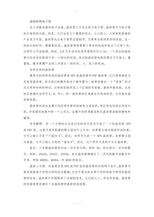
符号解释: 有一个方便的方式来记住的符号是否代表了一个结晶体管NPN 或PNP型。
注意代表发射器的箭头指向什么方向。
如果箭头指向相差形成的基,它可以被认为是“不指向N”,因此,该符号代表一个NPN晶体管。
如果箭头指向底座,它可以被认为是的“指向N”。
因此,这个符号代表的P-N-P晶体管。
鉴定: 大多数晶体管标识由一些字母代码,例如2N,然后通过一系列的数字,例如,2N104,2N337,2N556。
其它晶体管都确定了一系列的数字或数字和字母,例如40050,40404,和4D20的组合。
晶体上手册: 设备是否是NPN或PNP型的晶体管的识别码不表示。
晶体管手册或规格表中发现这样的技术数据。
这些手册也给各种不同的电路中使用的晶体管的信息。
晶体管外形图提供了详细的信息,它们的大小,形状和连接。
电气工程及其自动化专业英语第三章课文翻译

Semiconductor switches are very important and crucial components in power electronic systems.these switches are meant to be the substitutions of the mechanical switches,but they are severely limited by the properties of the semiconductor materials and process of manufacturing. 在电力电子系统,中半导体开关是非常重要和关键部件。
半导体开关将要替换机械开关,但半导体材料的性质和生产过程严重限制了他们。
Switching losses开关损耗Power losses in the power eletronic converters are comprised of the Switching losses and parasitic losses. 电力电子转换器的功率损耗分为开关损耗和寄生损耗the parasitic losses account for the losses due to the winding resistances of the inductors and transformers,the dielectric losses of capacitors,the eddy and the hysteresis losses. 寄生损失的绕组电感器、变压器的阻力、介电损耗的电容器,涡流和磁滞损耗the switching losses are significant and can be managed. 这个开关损耗是非常重要的,可以被处理。
they can be further divided into three components:(a)the on-state losses,(b)the off-state losses and the losses in the transition states. 他们可以分为三个部分: 通态损耗,断态损耗和转换过程中产生的损耗。
电气工程及其自动化专业英语第三章课文翻译
Semiconductor switches are very important and crucial components in power electronic systems.these switches are meant to be the substitutions of the mechanical switches,but they are severely limited by the properties of the semiconductor materials and process of manufacturing. 在电力电子系统,中半导体开关是非常重要和关键部件。
半导体开关将要替换机械开关,但半导体材料的性质和生产过程严重限制了他们。
Switching losses开关损耗Power losses in the power eletronic converters are comprised of the Switching losses and parasitic losses. 电力电子转换器的功率损耗分为开关损耗和寄生损耗the parasitic losses account for the losses due to the winding resistances of the inductors and transformers,the dielectric losses of capacitors,the eddy and the hysteresis losses. 寄生损失的绕组电感器、变压器的阻力、介电损耗的电容器,涡流和磁滞损耗the switching losses are significant and can be managed. 这个开关损耗是非常重要的,可以被处理。
they can be further divided into three components:(a)the on-state losses,(b)the off-state losses and the losses in the transition states. 他们可以分为三个部分: 通态损耗,断态损耗和转换过程中产生的损耗。
电气自动化专业英语1,2,3,5,8,13章翻译

第一章电子测量仪表电子技术人员使用许多不同类型的测量仪器。
一些工作需要精确测量面另一些工作只需粗略估计。
有些仪器被使用仅仅是确定线路是否完整。
最常用的测量测试仪表有:电压测试仪,电压表,欧姆表,连续性测试仪,兆欧表,瓦特表还有瓦特小时表。
所有测量电值的表基本上都是电流表。
他们测量或是比较通过他们的电流值。
这些仪表可以被校准并且设计了不同的量程,以便读出期望的数值。
1.1安全预防仪表的正确连接对于使用者的安全预防和仪表的正确维护是非常重要的。
仪表的结构和操作的基本知识能帮助使用者按安全工作程序来对他们正确连接和维护。
许多仪表被设计的只能用于直流或只能用于交流,而其它的则可交替使用。
注意:每种仪表只能用来测量符合设计要求的电流类型。
如果用在不正确的电流类型中可能对仪表有危险并且可能对使用者引起伤害。
许多仪表被设计成只能测量很低的数值,还有些能测量非常大的数值。
警告:仪表不允许超过它的额定最大值。
不允许被测的实际数值超过仪表最大允许值的要求再强调也不过分。
超过最大值对指针有伤害,有害于正确校准,并且在某种情况下能引起仪表爆炸造成对作用者的伤害。
许多仪表装备了过载保护。
然而,通常情况下电流大于仪表设计的限定仍然是危险的。
1.2基本仪表的结构和操作许多仪表是根据电磁相互作用的原理动作的。
这种相互作用是通过流过导体的电流引起的(导体放置在永久磁铁的磁极之间)。
这种类型的仪表专门适合于直流电。
不管什么时候电流流过导体,磁力总会围绕导体形成。
磁力是由在永久磁铁力的作用下起反应的电流引起。
这就引起指针的移动。
导体可以制成线圈,放置在永久磁铁磁极之间的枢钮(pivot中心)上。
线圈通过两个螺旋型弹簧连在仪器的端子上。
这些弹簧提供了与偏差成正比的恢复力。
当没有电流通过时,弹簧使指针回复到零。
表的量程被设计来指明被测量的电流值。
线圈的移动(或者是指针的偏移)与线圈的电流值成正比。
如果必须要测量一个大于线圈能安全负载的电流,仪表要包含旁路或者分流器。
电气工程及其自动化专业英语翻译(精选多篇)
电气工程及其自动化专业英语翻译(精选多篇)第一篇:电气工程及其自动化专业英语翻译Electric Power Systems.The modern society depends on the electricity supply more heavily than ever before.It can not be imagined what the world should be if the electricity supply were interrupted all over the world.Electric power systems(or electric energy systems), providing electricity to the modern society, have become indispensable components of the industrial world.The first complete electric power system(comprising a generator, cable, fuse, meter, and loads)was built by Thomas Edison – the historic Pearl Street Station in New York City which began operation in September 1882.This was a DC system consisting of a steam-engine-driven DC generator supplying power to 59 customers within an area roughly 1.5 km in radius.The load, which consisted entirely of incandescent lamps, was supplied at 110 V through an underground cable system..Within a few years similar systems were in operation in most large cities throughout the world.With the development of motors by Frank Sprague in 1884, motor loads were added to such systems.This was the beginning of what would develop into one of the largest industries in the world.In spite of the initial widespread use of DC systems, they were almost completely superseded by AC systems.By 1886, the limitations of DC systems were becoming increasingly apparent.They could deliver power only a short distance from generators.To keep transmission power losses(I 2 R)and voltage drops to acceptable levels, voltage levels had to be high for long-distance power transmission.Such high voltages were not acceptable for generation and consumption of power;therefore, a convenient means for voltage transformationbecame a necessity.The development of the transformer and AC transmission by L.Gaulard and JD Gibbs of Paris, France, led to AC electric power systems.In 1889, the first AC transmission line in North America was put into operation in Oregon between Willamette Falls and Portland.It was a single-phase line transmitting power at 4,000 V over a distance of 21 km.With the development of polyphase systems by Nikola Tesla, the AC system became even more attractive.By 1888, Tesla held several patents on AC motors, generators, transformers, and transmission systems.Westinghouse bought the patents to these early inventions, and they formed the basis of the present-day AC systems.In the 1890s, there was considerable controversy over whether the electric utility industry should be standardized on DC or AC.By the turn of the century, the AC system had won out over the DC system for the following reasons:(1)Voltage levels can be easily transformed in AC systems, thusproviding the flexibility for use of different voltages for generation, transmission, and consumption.(2)AC generators are much simpler than DC generators.(3)AC motors are much simpler and cheaper than DC motors.The first three-phase line in North America went into operation in 1893——a 2,300 V, 12 km line in southern California.In the early period of AC power transmission, frequency was not standardized.This poses a problem for interconnection.Eventually 60 Hz was adopted as standard in North America, although 50 Hz was used in many other countries.The increasing need for transmitting large amounts of power over longer distance created an incentive to use progressively high voltage levels.To avoid the proliferation of anunlimited number of voltages, the industry has standardized voltage levels.In USA, the standards are 115, 138, 161, and 230 kV for the high voltage(HV)class, and 345, 500 and 765 kV for the extra-high voltage(EHV)class.In China, the voltage levels in use are 10, 35, 110 for HV class, and 220, 330(only in Northwest China)and500 kVforEHVclass.Thefirst750kVtransmission line will be built in the near future in Northwest China.With the development of the AC/DC converting equipment, high voltage DC(HVDC)transmission systems have become more attractive and economical in special situations.The HVDC transmission can be used for transmission of large blocks of power over long distance, and providing an asynchronous link between systems where AC interconnection would be impractical because of system stability consideration or because nominal frequencies of the systems are different.The basic requirement to a power system is to provide an uninterrupted energy supply to customers with acceptable voltages and frequency.Because electricity can not be massively stored under a simple and economic way, the production and consumption of electricity must be done simultaneously.A fault or misoperation in any stages of a power system may possibly result in interruption of electricity supply to the customers.Therefore, a normal continuous operation of the power system to provide a reliable power supply to the customers is of paramount importance.Power system stability may be broadly defined as the property of a power system that enables it to remain in a state of operating equilibrium under normal operating conditions and to regain an acceptable state of equilibrium after being subjected to a disturbance..Instability in a power system may be manifested in many different ways depending on the system configurationand operating mode.Traditionally, the stability problem has been one of maintaining synchronous operation.Since power systems rely on synchronous machines for generation of electrical power, a necessary condition for satisfactory system operation is that all synchronous machines remain in synchronism or, colloquially “in step”.This asp ect of stability is influenced by the dynamics of generator rotor angles and power-angle relationships, and then referred to “ rotor angle stability ”译文:电力系统现代社会比以往任何时候更多地依赖于电力供应。
2012年 电气工程及其自动化专业英语翻译
�� � ���������������������������tdp
0t
t
��w
于等率功的供提件元由或收吸件元被 t 间时到 0t 间时从 �知可 �7�1� 程方从 。实事一这衡平相率功的收吸与须必率功的路电给供提了明证次一再这 �� � �����������������������0 � p � 零于等须必和数代的率功间瞬 何任在中路电一任�因原个这于由。律定恒守量能循遵须必中路电何任在�上实事 。率功供提或放释在是件元明表�时 示所�b�3�1 图如�0<iu 或 iu��p 果如而。率功收吸在是件元明表�0>iu 或 iu�p�下 况情种这在。极正的压电进流流电�说来例惯号符源无于对�例惯号符源无为称被况情种这 。致一的示所�a�3�1 图与须必向方的流电和性极的压电 �正为号符的率功使了为。因原要重的慎谨别特时系关的 u 压电和 i 流电的示显所�a�3� 1 图析分在们我是就这�用作的要主着起性极的压电和向方的流电�时号符率功定确们我在 �负为或正为率功时何知得何如们我但。的供提件元由是 率功么那�的负是号符的率功果如�面方一另。收吸件元被或放释件元向率功么那�的正是 号符的率功个这果如 。积乘的流电的它过通和压电端两件元于等率功的供提或收吸件元一某 �率功时瞬为称被是于量变间时个是 p 率功的中 �6�1� 程方 �数函的间时是常通 i 和 u 于由
�� � ������������������������我。得求分积边两�1�1�程方由可荷电的送移所 t 间时到 0t 间时从
td �� � ��������������������������� �i qd �是系关的间之 t 间时及 以 q 荷电、i 流电�说来上学数从。的量度来位单为培安以是它�率时的荷电是就流电是于 。动流的纯单的荷电正是作看流电把即�例惯的用通循遵将们我但�的起引荷电负由是流电 的中体导属金道知在现们我然虽 。的入引林克兰富�明杰本家明发和家学科国美由是例惯一 这。示所 1�1 图如�反相向方动流的荷电负与�即也�动移的荷电正是作看流电把地便方 很以可们我 。流电了生产动移的荷电种这 。动移向方的反相朝荷电负而动移向方个一朝荷电 正 �动移使驱力外被荷电 �)源势动电种一(时上池电一某到接连线导根一把们我当 。量能的式形种一外另成换转被以可它此在�方地个一另到送移被方 地个一从以可它�是就也�性特的动运其是性特的电或荷电。动流的荷电下一虑考来们我让 。性中 电现呈子原得使同相量数子电和子质 。等相子电与上值数在量电正的带所子质而 �C21-01× 001206.1 于等上值数在且并的负是量电的子电道知还们我 。的成组子中和子质 �子电由是子 原个每且并�的成组分部造构本基的子原为称被由是质物切一知得理物础基从们我 。的量度来位单为仑库以是它�性属气电的粒微子原的质物成构是荷电 。荷电是量的本基最中路电 �即也 。念概本基的象现气电有所释解来用是念概的荷电 流电和荷电 。系关种各的路电了划刻们它�量变个两的本基最中路电是量变个两这)t(i 和)t(u 章一第
电气自动化专业英语第三单元
电气自动化专业英语第三单元专业英语第三单元3 Analog Electronics3.1 INTRODUCTION3.1.1 The Contrast between Analog and Digital ElectronicsWe have already explored how transistors and diodes are used as switching devices to process information which is represented in digital form. Digital electronics uses transistors as electrically controlled switches: transistors are either saturated or cut off. The active region is used only in transition from one state to the other.By contrast, analog electronics depends on the active region of tran sistors and other types of amplifiers. The Greek roots of “analog” mean “in due ratio”, signifying in this usage that information is encoded into an electrical signal which is proportional to the quantity being represented.713宿舍In Fig.3.1 our information is some sort of music, originating physically in the excitation and resonance’s of a musical instrument. The radiated sound consists in the ordered movement of air molecules and is best understood ad acoustic waves. These produce motion in the diaphragm of a microphone, which in turn produces an electrical signal. The variation in the electrical signal are a proportional representation of the sound waves. The electrical signal is amplifiedelectronically, with an increase in signal power occurring at the expense of the input AC power to the amplifier. The amplifier output drives a recording head and produces a wavy groove on a disk. If the entire system is good, every acoustic variation of the air will be recorded on the disk and, when the record is playedback through a similar system and the signal reradiated ad sound energy be a loudspeaker, the resulting sound should faithfully reproduce the original music.Electronic systems based on analog principles form an important class of electronic devices. Radio and TV broadcasting are common examples of analog systems, as are many electrical instruments used in monitoring deflection(strain gages, for example), motion (tachometers), and temperature (thermocouples).Many electrical instruments-voltmeters, ohmmeters, ammeters, and oscilloscopes-utilize analog techniques, at least in part.Analog computers existed before digital computers were developed. In an analog computer, the unknowns in a differential equation are modeled with electrical signals. Such signals are integrated, scaled, and summed electrically to yield solutions with modes effort compared with analytical or numerical techniques.3.1.2 The Contents Of This ChapterAnalog techniques employ the frequency-domain viewpoint extensively. We begin by expanding our concept of the frequency domain to include periodic, nonperiodic, and random signals. We will see that most analog signals and processes can be represented in the frequency domain. We shall introduce the concept of a spectrum, that is, the representation of a signal as the simultaneous existence of many frequencies. Bandwidth (the width of a spectrum) in the frequency domain will be related to information rate in the time domain.714宿舍This expanded concept of the frequency domain also helps us distinguish the effects of linear and nonlinear analog devices. Linear circuits are shown to be capable of“filtering” out unwanted frequency components. By contrast, new frequencies can be created by nonlinear devices such as diodes and transistors. This property allows us to shift analog signals in the frequency domain through AM and FM modulation techniques, which are widely used in public and private communication systems. As an example we shall describe the operation of an AM radio.Next we study the concept of feedback, a technique by which gain in analog systems is exchanged for other desirable qualities such as audio amplifiers or TV receivers would at best offer poor performance. Understanding of the benefits of feedback provides the foundation for appreciating the many uses of operational amplifiers in analog electronics.Operational amplifiers (op amps, for short) provide basic building blocks for analog circuits in the same way that NOR and NAND gates are basic building blocks for digital circuits. We will present some of the more common applications of op amps, concluding with their use in analog computers.3.3.2 OPERATIONAL-AMPLIFIER CIRCUITS3.2.1 Introduction(1) The Importance of OP Amps. An operational amplifier isa high-gain electronic amplifier which is controlled by negative feedback to accomplish many functions or “operations” in analog circuits. Such amplifiers were developed originally to accomplish operations such as integration and summation in analog computers for the solving of differential equations. Applications of op amps have increased until, at the present time, most analog electronic circuits are based on op amp techniques. If, for example, you required an amplifier with of 10, convenience, reliability, and cost considerations would dictate the use of an opamp. Thus op amp from the basic building blocks of analog circuits much as NAND and NOR gates provide the basic building blocks of digital circuits.(2) An OP-Amp Model Typical Properties. The typical op amp is a sophisticated transistor amplifier utilizing a dozen or more transistors,several diodes, and many resistors. Such amplifiers are mass produced on semiconductor chips and sell for less than $1 each. These parts are reliable, rugged, and approach the ideal in their electronic properties.Fig.3.2 shows the symbol and the basic properties of op amp. The two input voltages, u+and u-, are subtracted and amplified with a large voltage gain, A, typically 105~106. The input resistance, Ri, is large, 100KΩ~100MΩ. The output resistance, Ro, is small, 10~100Ω. The amplifier is often supplied with DC power from positive (+Ucc)and negative(﹣Ucc) power supplies. For this case, the output voltage lies between the power supply voltages, ﹣Ucc﹤Uo﹤+Ucc. Sometimes one power connection is grounded (i.e., “﹣Ucc”=0). In this case the output lies in the range, 0﹤Uo﹤+Ucc. The power connections are seldom drawn in circuit diagrams; it is assumed that one connects the op amp to the appropriate power source. Thus the op amp approximates an ideal voltage amplifier, having high input resistance, low output resistance, and high gain.The high gain is converted to other useful features through the use of strong negative feedback.All the benefits of negative feedback are utilized by op-amp circuits. To those listed earlier in this chapter, we would for op-amp circuits add three more: low expanse, ease of design, and simple construction.(3)The Contents of This Section. We begin by analyzing twocommonop-amp applications, the inverting and uninverting amplifiers. We derive the gain of these amplifiers by a method that may be applied simple and effectively to any op-amp circuit. We then discuss active filters, which are op amp amplifiers with capacitors added to shape their frequency response. We then deal briefly with analog computers and conclude by discussing some nonlinear application of op-amp.3.2.2 Op-amp Amplifiers712宿舍(1) The Inverting Amplifier. The inverting amplifier, show in Fig.3.3, use an op-amp plus two resistors. The positive (+)input to the op-amp is grounded (zero signal); the negative (﹣)input is)and to the feedback signal from the connected to the input signal (via R1output (via R). One potential source of confusion in the followingFdiscussion is that we must speak of two amplifiers simultaneously. The op amp is an amplifier which forms the amplifying element in a feedback amplifier which contains the op amp plus associated resistors. To lessen confusion, we shall reserve the term “amplifier”to apply only to the overall, feedback amplifier. The op-amp will never be call ed an amplifier; it will be called the op-amp. For example, if we refer to the input current to the amplifier, we are referring to the current through Ri, not the current into the op-amp.We could solve for the gain of the inverting amplifier in Fig.3.3 either by solving the basic circuit laws (KCL and KVL) or byattempting to divide the circuit into main amplifier and feedback system blocks. We shall, however, present another approach based on the assumption that the op-amp gain is very high, effectively infinite. In the following, we shall give a general assumption, which may be applied to any op-amp circuit; then we will apply this assumption specifically to the present circuit. As a result, we will establish and input resistance of the inverting amplifier.We assume that the output is well behaved and does not try to go to infinity. Thus we assume that the negative feedback stabilizes the amplifier such that moderate input voltages produce moderate output voltages. If the power supplies are +10 and﹣10V, for example, the output would have to lie between these limits.Therefore, the input voltage to the op-amp is very small, essentially zero, because it is the output voltage divided by the large voltage gain of the op-ampu+﹣u_≈0?u+≈u_For example, if ∣Uo∣﹤10V and A=105, then ∣u+﹣u_∣﹤10\105=1+and u_ are equal with 100μV or less,for any op-amp circuit. For the inverting amplifier in Fig.3.3, u+is ground;therefore, u_≈0. Consequently, the current at the input to the amplifierwould bei 1= 1_R u Ui - ≈1R Ui (3.1) Because u +≈u_ and Ri is large, the current into the + and – op-ampinputs will be very small, essentially zero∣i +∣=∣i -∣=||RiU U +--≈0 (3.2) For example, for Ri =100KΩ, |i_|﹤104-/105=109-A.For the inverting amplifier, Eq. (3.2) implies that the current at the input, i i , flows through R f , as shown in Fig.3.4. This allows us to compute the output voltage. The voltage across R F would be i i R F and, because one end of R F is connected to u_≈0 Uo=-i i R F =-1R U i R F Thus the voltage gain would beA u =Ui Uo =1R R F - (3.3) The minus sign in the gain expression means that the output will be inverted relative to the input: a positive signal at the input: a positive signal at the input will produce a negative signal at the output, Eq. (3.3) shows the gain to depend o the ratio R F to R 1. This would imply that onlythe ratio and not the individual values of R F to R 1 matter. This would betrue if the input resistance to the amplifier were unimportant, but the input resistance to an amplifier is often critical. The input resistance to the inverting amplifier would follow from Eq. (3.1);R i =i i i U ≈R 1 (3.4)For a voltage amplifier, the input resistance is an importantfactor, for if R i were too low the signal source (of U i ) could be loaded down by R i . Thus in a design, R 1 must be sufficiently high to avoid his loadingproblem. Once R 1 is fixed, R F may be selected to achieve the requiredgain. Thus the values of individual resistors become important because they affect the input resistance to the amplifier.Let us design an inverting amplifier to have a gain of ﹣8. The input signal is to come from a voltage source having an output resistance of 100Ω. To reduce loading, the input resistor, R 1, must be much larger than100Ω. For a 5﹪loading reduction, we would set R 1=2000Ω. To achievea gain of -8(actually 95﹪of -8, considering loading ), we require that R F =8×2000=16KΩ.Feedback effects dominate the characteristics of the amplifier. When an input voltage is applied, the value of u_ will increase. This will cause U 0 to increase rapidly in the negative direction . This negative voltagewill increase to the value where the effect of U 0 on the –input via R F cancels the effect of U i through R 1. Put another way, the output willadjust itself to withdraw through R F any current that U i injects through R 1, since the input current to the op-amp is extremely small. In this waythe output depends only R F and R 1.711宿舍 The Noninverting Amplifier. For thenoninverting amplifier show in Fig.3.5 the input is connected to the +input. The feedback from the output connects still to the– op amp input, as required for negative feedback. T o determine the gain, we apply the assumptions outlined above.①Because u +≈u_, it follows thatu_ ≈U i (3.5)②Because i ≈0, R F and R 1 carry the same current. Hence U0 is related to u_ through a voltage-divider relationshipu i =U 0 FR R R +11(3.6) Combining Eqs. (3.5) and (3.6), we establish the gain to beU i =U 0F R R R +11=A u =+(1+1R R F ) (3.7) The + sign before the gain expression emphasize that the output of the amplifier has the same polarity as the input: a positive input signal produces a positive output signal. Again we see that the ratio of R F and R 1 determines the gain of the amplifier.When a voltage is applied to the amplifier, the output voltage increase rapidly and will continue to rise until the voltage across R 1 reaches theinput voltage. Thus little input current will flow into the amplifier, and the gain depends only on R F and R 1. The input resistance to the noninvertingamplifier will be very high because the input current to the amplifier is also the input current to the op-amp, i +, which must be extremely small.Input resistance values exceeding 1 000 MΩ are easily achieved with this circuit. This feature of high input resistance is an important virtue of the noninverting amplifier.3.2.3 Active Filters(1)What Are Active Filters? An active filter combines amplification with filtering. The RC filters we investigated earlierare called passive filters because they provide only filtering. An active filter uses an op-amp to furnish gain but has capacitors added to the input and feedback circuits to shape the filter characteristics.We derived earlier the gain characteristics of an inverting amplifier in the time domain. In Fig.3.6 we show the frequency-do-main version. We may easily translate the earlier derivation into the frequency domainU i ?U i (ω) U 0?U 0(ω)A u =﹣1R R F ?F u (ω)=﹣)()(1ωωZ Z F The filter function, F u (ω), is thus the ratio of the two impedances,and in general with give gain as well as filtering. We could have written the minus sign a s 180°, for in the frequency domain the inversion is equivalent to a phase shift of 180°.(2) Low-pass Filter. Placing a capacitor in parallel with R F (seeFig.3.7) will at high frequencies tend to lower Z and hence the gain of the amplifier; consequently, this capacitor an inverting amplifier into a low-pass filter with gain. We may writeF Z (ω)=R F ∣∣F C j ω1=F F C j R ω+)/1(1=FF F C R j R ω+1(3.8) Thus the gain would be)/(11111c u F F F u j A C R j R R F ωωω+=+-=(3.9) Where 1/R R Au F -=, the gain without the capacitor, andF C C R R /1=ωwould be the cutoff frequency. The gain of the amplifier isapproximately constant until the frequency exceeds C ω, after which thegain decreases with increasing ω. The Bode plot of this filter function is shown in Fig.3.8 for the case where R F =10K ωΩ, R1=1KΩ, and C F =1μF.(3) High-pass filter. The high-pass filter show in Fig.3.9 usesa capacitor in series with R 1 to reduce the gain at low frequencies. Thedetails of the analysis will be left to a problem. The gain of this filter isu c c F u A j j R R F =+-=)/(1)/()(1ωωωωω)/(1)/(c c j j ωωωω+ Where 1/R R Au F -= is the gain without the capacitor and 11/1C R c =ω is the cutoff frequency, below which the amplifier gain is reduced. The Bode plot of this filter characteristic is show in Fig.3.10.(4) Other Active Filter. By using more advanced techniques, one can simulate RLC narrowband filters and, by using additional op-amps, many sophisticated filter characteristics can be achieved. Discussion of such applications lies beyond the scope of this text, but there exist many handbooks showing circuits and giving design information about active filters.3. 2. 4 Analog ComputerOften a differential equation is Fig.3.10 solved by integration. The integration may be accomplished by analytical methods or by numerical methods on a digital computer. Integration may also be performed electronically with an op-amp circuit. Indeed, op-amps were developed initially for electronic integration of differential equations.⑴ An Integ rator . The op-amp circuit in Fig.3.11 uses negative feedback through a capacitor to perform integration.We have charge the capacitor in the feedback path to an initial value of U 1, and then removed this prebias(预偏置)voltage at t=0. Let usexamine the initial state of the circuit before investigatingwhat will happen after the switch is opened. Since +u is approximately zero, sowill be _u , and hence the output voltage is fixed at ﹣1U . The inputcurrent to amplifier, R U i /, will flow through the 1U voltage will remainat ﹣1U until the switch is opened.After the switch is opened at t=0, the input current will flow through the capacitor and hence the U C will be,0,0)()0()(dt RC t U U t Uc ti ?+= Thus the output voltage of the circuit is0)(1)()(,,010≥--=-=?t dt t U RC U t U t U ti c (3.10)Except for the minus sign, the output is the integral of U i scaled by1/RC, which may be made equal to any value we wish by proper choiceof R and C.⑵ Scaling and Summing . We need two other circuits to solve simple differential equations by analog computer methods. Scaling refers to multiplication by a constant, such as 12KU U ±=Where K is a constant. This is the equation of an amplifier, and hence we would use the inverting amplifier in Fig.3.5 for the – sign or the noninverting amplifier in Fig.3.5 for the + sign.A summer produces the weighted sum of two or more signals.Fig.3.12 shows a summer with two inputs. We may understand the operation of the circuit by applying the same reasoning we used earlier to understand the inverting amplifier. Since 0≈-u , the sum of the currents through 1R and 2R is22111R U R U i +=(3.11) The output voltage will adjust itself to draw this current through RF, and hence the output voltage will be)(221110R R U R R U R i U F F F ?+?-=-= The output will thus be sum of 1U and 2U , weighted by the gainfactors, 1/F R R and 2F R R , respectively. If the inversion produced by thesummer is unwanted, the summer can followed by an inverted, a scalier with a gain of -1. Clearly, we could add other inputs in parallel withR R and 21. In the example to follow, we shall sum three signals to solve a second order differential equation.(3) Solving a DE. Let us design an analog computer circuit tosolve the differential equation t u dt du dtu d 10cos 65222=++ t>0 U(0)=﹣2 and at dtdu 3+= t=0 (3.12) Moving everything except the highest-order derivative to the right side yields t u dt du dtu d 10cos 32222+--=(3.13)女生宿舍The circuit which solves Eq. (3.12) is shown in Fig.3.13. The circuit consists of two integrators to integrate the left side of Eq. (3.13), a summer to represent the right side, and two inverts to correct the signs. The noninverting inputs are grounded, and the inputs and feedback are connected to the inverting input of the op-amps. Hence we have shown only the inverting inputs. With 22/dt u d the input to the integrators, the output of the first integrator will be-du/dt [with the battery giving the initial condition of 3V , as in Eq. (3.13)], and hence the output of the second integrator will be +u (withan initial condition of -2 V ). This output is fed into the summer, along with du/dt after inversion, and the driving function cos10 t, which must also be inverted to cancel the inversion in the summer. The input resistors connecting the three signals into the summer produce the weighting factors in Eq. (3.13), and hence the output of the summer represents the right side of Eq. ( 3.13 ). Wetherefor e connect that output to our “input” of 22/dtd to satisfy Eq.u(3.12 ). To observe the solution to Eq. (3.12 ), we merely open the switches at t=0.Clearly, these techniques can be applied to higher-order equations. Sophisticated use of analog computer requires a variety of refinements. Often, the equations being solved are scaled in time (time is sped up or slowed down on the computer) to accommodate realistic resistor and capacitor values. Also, voltage and current values can be scaled to bring the unknowns within the allowable range of the computer. In the next section we show how nonlinear operations can be introduced to solve nonlinear differential equations by analog methods.3. 2. 5 Nonlinear Applications of Op-ampsOp-amps can be combined with nonlinear circuit elements such as diodes and transistors to produce a variety of useful circuits. Below we discuss a few such applications. Many more circuits are detailed in standard handbooks and manufacturers’ application literature for their products.An Improved Half-Wave Rectifier. The op-amp in Fig 3.14 drives a half-wave rectifier. When the input voltage is negativethe output of the op-amp will be OFF; hence the output will be zero. When the output is positive the diode will turn ON and the output will be identical to the input, because the circuit will perform as a non-inverting amplifier shownin Fig.3.5 with R F=0. Use of the op-amp effectively reduces the diode turn-on voltage. If the input voltage is greater than 0.7/A, where A is the voltage gain of the op-amp, the output voltage exceed 0.7V and turn on the diode. Hence the turn-on voltage is effectively reduced from 0.7~0.7/A.This circuit would not be used in a power supply circuit; rather, it would be used in a detector or other circuit processing small signals, where the turn-on voltage of the diode would be a problem.。
电气工程与自动化专业英语中文翻译
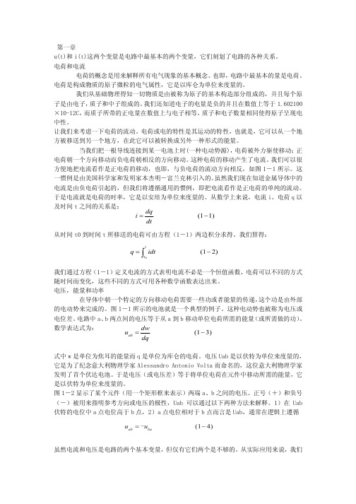
第一章 电路基本原理第一节 电流与电压u(t )和i(t )这两个变量是电路中最基本的概念,描述了电路中各种不同的关系.电荷与电流电荷与电流的概念是解释一切电气现象的基础原则。
而电荷也是电路的最基本的量。
电荷是构成物质的原子的电气属性,单位是库仑(C )。
通过基础物理学,我们了解到一切物质都是由被称为原子的基本粒子构造而成的,每个原子中都包含电子、质子和中子。
我们还知道电子上的电荷带负电,每个电子上的电量是1.60210×10—19库仑。
质子带与电子相等的正电荷。
原子上质子与电子的数目相等,使其呈中性.我们来考虑电荷的运动。
电或电荷的独特之处就是它们可以移动,也就是说电荷可以从一个地方移动到另一个地方,从而转换成另外一种形式的能量。
当把一根导线接在电池(一种电源)的两端时,电荷受迫而运动;正电荷与负电荷分别向相反的两个方向移动。
这种电荷的移动产生了电流。
习惯上,我们把正电荷移动的方向或负电荷移动的反方向称为电流的方向,如图1-1所示。
这种说法是由美国科学家、发明家本杰明·富兰克林提出的。
即使我们知道金属导体中的电流是由于带负电荷的电子(运动)而产生的,(我们)也使用默认的习惯,将正电荷运动的方向定义为电流的方向.因此,电流是单位时间内电荷的变化率,单位是安培(ampere,A ).在数学上,电流i 、电荷q 和时间t 的关系为i=dtdq (1—1)将等式的两边同时进行积分,则可得到电荷在时间t 和t 0之间的变化。
有q== 0t t idt (1-2)在等式(1—1)中我们给电流i 的定义表现了电流不是一个定值量,电荷随时间的变化不同,电流也与之呈不同的函数关系。
电压、电能与电功率使电子在导体中定向运动需要做功或能量转换.功由外电动势提供,最典型的就是图1—1中的电池.外电动势也可理解为电压或电位差。
电路中,a 、b 两点之间的电压U ab 等于从a 到b 移动单位电荷所需能量(所做的功),有U ab =dqdw (1—3) w 代表电能,单位是焦耳(J );q 代表电量.单位是库仑(C )。
电气工程及其自动化专业英语

time-invariant 时不变的
self-(or mutual-)induction 自(互)感
displacement current 位移电流 conductance 电导
voltage drop 电压降 volt-ampere characteristics 伏安特性
metal-filament lamp 金属丝灯泡
seen, increase of current from zero to
I≈I1 causes the terminal voltage of the source to decrease linearly
V12=V=E-VS=E-RSI
Fig.1.3
In other words, the voltage drop VS across the source resistance rises in proportion to the current. This goes on until
电气工程及其自动化专业英语第三章section_3-2

Section 2 The DC-DC Converters
Text New Words and Expressions Transition of part of speech Exercises End
Section 2 The DC-DC Converters
Section 2 The DC-DC Converters
If the duty ratio D is made a linear function of uC, a control voltage
D = ku C
U o = (kU S )u C
(3-6)
The output voltage is then a linear function of the control voltage. This is also the principle of switchmode linear amplifier. The gain of this amplifier is determined by the input dc source voltage. Neglecting the power losses in the circuit elements, we could use the equation of the balance of power
Section 2 The DC-DC Converters
US I S = Uo Io
− −
(3-7)
where IS is the average current from the DC source. Hence,
Io
−
=
翻译电气工程及其自动化专业英语3
Active power and frequency control有功功率和频率控制
For satisfactory operation of a power system, the frequency should remain nearly constant. Relatively close control of frequency ensures constancy of speed of induction and synchronous motors. Constancy of speed ofmotor drives is particularly important for satisfactory performance of all the auxiliary drives associated with the fuel, the feed-water and the combustion air supply systems. In a network, considerable drop in frequency could result in high magnetizing currents in induction motors and transformers .对于电力系统运行合格的,频率应该保持几乎不变。较为密切的保证电动机变频调速同步恒定速度感应和。驱动电机转速恒定,尤其是在重要的关联的所有辅助驱动器的表现令人满意燃料,饲料,水和空气供给系统燃烧。在网络,大幅下降的频率可能会导致电机和变压器激磁电流的高感应。The extensive use of electric clocks and the use of frequency for other timing purpose require accurate maintenance of synchronous time which is proportional to integral of frequency. As a consequence, it is necessary to regulate not only the frequencyitself but also its integral. The frequency of a system is dependant on active power balance. As frequency is a common factor throughout the system, a change in active power demand at one point is reflected throughout the system by a change in frequency.广泛使用的电动时钟和定时的目的使用的频率为其他需要作为一个同步时间是成正比的积分。结果准确的频率维持,它是要规范,不仅本身的频率,而且它的积分。该系统是一个频率依赖于积极的力量平衡。由于频率是1点共同的因素在整个系统,有源电力需求的变化是反映整个系统的频率变化。
(电气工程与自动化专业英语)Chapter 3 Signals and Systems

19
3.3 Discrete-Time Signals
1 The basic definition signals
The fundamental results of signal theory : Analog signal can be converted into a discrete-time one and retrieved without error. This result is important because discrete-time signals can be manipulated by systems instantiated as computer programs. Subsequent modules describe how virtually all analog signal processing can be performed with software.
16
3.2 Signal Decomposition
As an example of signal complexity, we can express the pulse as a sum of delayed unit steps.
电气工程专业英语+unt3

3.1 Introduction text 3.1.2 Classification of Electrical Machines Electrical machines are classified as D.C. and A.C. machine as shown in Fig.3.1. When classifying electrical machines (motors and generators), it is reasonable to start with physical principle for converting electrical energy to mechanical energy. It is important to distinguish between the machine and the controller, regardless of the controller being a separate inverter or if it is built into the motor in the form of a com-mutator.
Note:①:family of electrical machines电机的家族。尽管变 压器不含旋转部件,但由于它们也是利用电磁感应现象来传递 能量,所以也属于电机。
3.1 Introduction text
Electrical machines have become so ubiquitous that they are virtually overlooked as① an integral component of the entire electricity infrastructure②. Developing ever more efficient electrical machine technology is crucial to any global conservation, green energy, or alternative energy strategy.
- 1、下载文档前请自行甄别文档内容的完整性,平台不提供额外的编辑、内容补充、找答案等附加服务。
- 2、"仅部分预览"的文档,不可在线预览部分如存在完整性等问题,可反馈申请退款(可完整预览的文档不适用该条件!)。
- 3、如文档侵犯您的权益,请联系客服反馈,我们会尽快为您处理(人工客服工作时间:9:00-18:30)。
电气工程及其自动化专业英语第三章翻译Semiconductor switches are very important and crucial components in power electronic systems.these switches are meant to be the substitutionsof the mechanical switches,but they are severely limited by the propertiesof the semiconductor materials and process of manufacturing. 在电力电子系统,中半导体开关是非常重要和关键部件。
半导体开关将要替换机械开关, 但半导体材料的性质和生产过程严重限制了他们。
Switching losses开关损耗Power losses in the power eletronic converters are comprised of the Switching losses and parasitic losses. 电力电子转换器的功率损耗分为开关损耗和寄生损耗the parasitic losses account for the losses due to the windingresistances of the inductors and transformers,the dielectric lossesofcapacitors,the eddy and the hysteresis losses. 寄生损失的绕组电感器、变压器的阻力、介电损耗的电容器,涡流和磁滞损耗the switching losses are significant and can be managed. 这个开关损耗是非常重要的,可以被处理。
they can be further divided into three components:(a)the on-state losses,(b)the off-state losses and the lossesin the transition states. 他们可以分为三个部分: 通态损耗,断态损耗和转换过程中产生的损耗。
On-State Losses:The electrical switches conduct heavy current and have nonzero voltageacross the switch in the on-state.The on-state power losses aregiven byPon=Uson if.这个电子开关能导通大电流,并且在通态时有非零的压降。
这个通态功率损耗的公式为Pon=Uson if.The Uson and If are respectively the switch voltage in the on-state and the forward current through the switch.For example,the typical powerdiodes and the power transistors have nearly 0.5 to l volt across themin the on-state.The forward currents can be hundreds to thousands of amperes.The on-state power losses are very significant. 其中Uson是通态时开关上的压降,if是流过开关的电流。
例如,典型的功率二极管和功率晶体管有近似0.5~1伏的通态压降。
而电流会有数百到数千安培。
这个通态损耗非常重要。
Off-State Losses断态损耗The electrical switches withstand high voltages and have nonzeroleakage current through the switch in the off-state.The off-state powerlesses are given by Poh=Uoff ir在关断状态时,电子开关到经受得起高电压,并会有非零的漏电流。
断态损耗的公式为Poh=Uoff ir.The Usoff and Ir are respectively the reverse bias voltage in the off-state and the reverse current through the switch.For example,the typical power diodes and the power transistors have high reverse voltagesin hundreds to thousands of volts and microamps to milliamps through themin the off state. 其中Uoff在断态时的反向偏置电压,ir是流过开关的反向漏电流。
例如,典型的功率二极管和功率晶体管有很高的反向压降几百到几千伏和几微安到几毫安的漏电流。
Transition-State Losses:The practical switching devices have limited capabilities of rate of voltage transition and the rate of current steering.These nonabrupt transition rates give rise to power losses in the switchingdevices.Wewill examine these switching losses in two cases separately:the inductiveand capacitive loads. 在实际的开关装置限制了电压变换率和电流变化率。
非突变引起了开关装置的功率损耗。
我们测试开关损耗时分两种情况:感性负载和容性负载。
Switching with Inductive Load:The indutor is assumed to be large so that the current through it in steady state is nearly constant Io.Assume that initially the switchisoff.The inductor current is +Io and freewheels through diode V1.When theswitch is turned on,the current through the switch begins to builduplinearly(an assumption)to+Io while the diode V1 is still on.The on diode has zero voltage across it(an ideal diode),hence,the voltageon theswitch is held constant at+Us.When the current buildup is over,the diodeV1 ceases to conduct and the voltage on the switch rampslinearly(againan assumption)down to zero. 假设电感无穷大,即在稳定时流经电感的电流是恒定的Io,假定开始时开关处于关断状态。
电感电流为+Io惯性流过二极管V1。
当开关闭合后,电流流经开关开始建立线性上升+Io此时二极管扔导通。
二极管压降为0,此时开关两端电压维持在+Us当电流建立完成后,二极管V1截止,开关两端电压线性下降为0。
When the switch is turned off ,the voltage begins to build up linearlyto +us while the diode V1 is off. while the diode is off the current throughthe switch equals the inductor current,which is constant I0 After theswitch voltage reaches aero, the current through the switch begins todecrease below I0,as the remaining current is now steered through thediode V1 which has now turned on The current through the swithch rampsdown to zero ultimately. Switching waveforms with inductive load are shownin Fig.3-1开关打开后,开关两端电压线性上升至Us。
此时二极管仍截止,二极管截止,流过开关的电流相当于流过电感的电流,维持在恒定的Io。
开关电压到0时,通过开关的电流开始上升到Io以下。
此时余留的电流正转向二极管V1,V1导通。
最终通过开关的电流下降到0,开关过程的波形的电感负载波形见图3-1The switching losses are given by : Psw=1/2UsIo[……….]fsPsw=1/2UsIo[……….]fsThe switching power losses increase linearly with the switchingrequency like in the resistive case but about six times more. The upperbound on the switching frequency is also about half. 开关功率损耗线性增加随着开关频率此时的损耗要比阻性负载损耗的6倍还多。
当f取最大时Psw=1/2UsIo。
Switching with capacitive LoadThe capacitor is assumed to be large so that the voltage through is in stedy state is nearly constant U0.Assume that initially the switch ison,hence,the cuttent through the switch is IS.The capacitor voltage isU the voltage across the switch is zero and the diode V1is reverse biased.When the switch is turned off,the switch voltage begins to rampup to+U0 while the diode V1 is still off.During this buildup,the currentthrough the switch is held constant at Is.Wheng the voltage buildup isover,the diode V1begins to conduct and the voltage on the switch is clampedat U0,and the current through the switch ramps linearly(again an assumption)down to zero. 假设电容器很大,致使在稳定状态下其两端电压接近为常数Uo。