离合器基础知识(中英版)
离合器
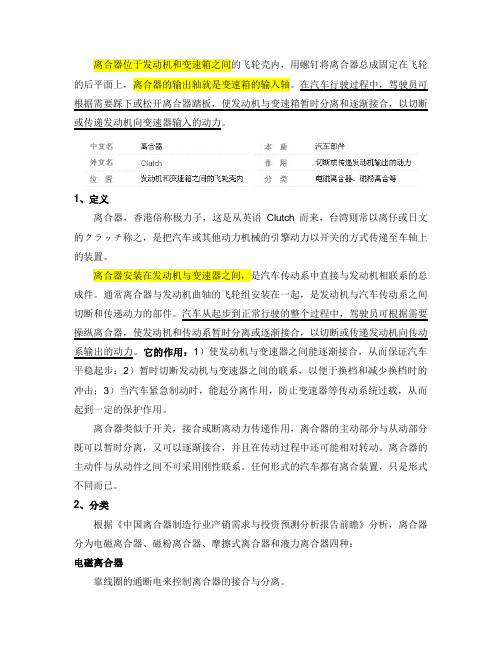
离合器位于发动机和变速箱之间的飞轮壳内,用螺钉将离合器总成固定在飞轮的后平面上,离合器的输出轴就是变速箱的输入轴。
在汽车行驶过程中,驾驶员可根据需要踩下或松开离合器踏板,使发动机与变速箱暂时分离和逐渐接合,以切断或传递发动机向变速器输入的动力。
1、定义离合器,香港俗称极力子,这是从英语Clutch而来,台湾则常以离仔或日文的クラッチ称之,是把汽车或其他动力机械的引擎动力以开关的方式传递至车轴上的装置。
离合器安装在发动机与变速器之间,是汽车传动系中直接与发动机相联系的总成件。
通常离合器与发动机曲轴的飞轮组安装在一起,是发动机与汽车传动系之间切断和传递动力的部件。
汽车从起步到正常行驶的整个过程中,驾驶员可根据需要操纵离合器,使发动机和传动系暂时分离或逐渐接合,以切断或传递发动机向传动系输出的动力。
它的作用:1)使发动机与变速器之间能逐渐接合,从而保证汽车平稳起步;2)暂时切断发动机与变速器之间的联系,以便于换档和减少换档时的冲击;3)当汽车紧急制动时,能起分离作用,防止变速器等传动系统过载,从而起到一定的保护作用。
离合器类似于开关,接合或断离动力传递作用,离合器的主动部分与从动部分既可以暂时分离,又可以逐渐接合,并且在传动过程中还可能相对转动。
离合器的主动件与从动件之间不可采用刚性联系。
任何形式的汽车都有离合装置,只是形式不同而已。
2、分类根据《中国离合器制造行业产销需求与投资预测分析报告前瞻》分析,离合器分为电磁离合器、磁粉离合器、摩擦式离合器和液力离合器四种:电磁离合器靠线圈的通断电来控制离合器的接合与分离。
磁粉离合器在离合器的主动件与从动件之间放置磁粉,不通电时磁粉处于松散状态,通电时磁粉结合,主动件与从动件同时转动。
优点:可通过调节电流来调节转矩,允许较大滑差。
缺点:较大滑差时温升较大,相对价格高。
摩擦离合器摩擦离合器是应用最为广泛,也是历史最为悠久的一类离合器,它基本上是由主动部分、从动部分、压紧机构和操纵机构四部分组成。
中英文文献翻译—离合器的简单介绍
附录A对于手动挡的车型而言,离合器是汽车动力系统的重要部件,它担负着将动力与发动机之间进行切断与连接的工作。
在城市道路或者复杂路段驾驶时,离合器成了我们最频繁使用的部件之一,而离合器运用的好坏,直接体现了驾驶水平的高低,也体现了对于车辆保护的好坏。
正确使用离合器,掌握离合器的原理以在特殊情况下利用离合器来解决问题,是每个驾驶手动挡车型的车友应该掌握的。
所谓离合器,顾名思义就是说利用“离”与“合”来传递适量的动力。
离合器由摩擦片,弹簧片,压盘以及动力输出轴组成,布置在发动机与变速箱之间,用来将发动机飞轮上储存的力矩传递给变速箱,保证车辆在不同的行驶状况下传递给驱动轮适量的驱动力和扭矩,属于动力总成的范畴。
在半联动的时候,离合器的动力输入端与动力输出端允许有转速差,也就是通过其转速差来实现传递适量的动力。
离合器分为三个工作状态,即不踩下离合器的全连动,部分踩下离合器的半连动,以及踩下离合器的不连动。
当车辆在正常行驶时,压盘是紧紧挤靠在飞轮的摩擦片上的,此时压盘与摩擦片之间的摩擦力最大,输入轴和输出轴之间保持相对静摩擦,二者转速相同。
当车辆起步时,司机踩下离合器,离合器踏板的运动拉动压盘向后靠,也就是压盘与摩擦片分离,此时压盘与飞轮完全不接触,也就不存在相对摩擦。
最后一种,也就是离合器的半连动状态。
此时,压盘与摩擦片的摩擦力小于全连动状态。
离合器压盘与飞轮上的摩擦片之间是滑动摩擦状态。
飞轮的转速大于输出轴的转速,从飞轮传输出来的动力部分传递给变速箱。
此时发动机与驱动轮之间相当于一种软连接状态。
一般来说,离合器是在车辆起步和换挡的时候发挥作用,此时变速箱的一轴和二轴之间存在转速差,必须将发动机的动力与一轴切开以后,同步器才能很好的将一轴的转速保持与二轴同步,挡位挂进以后,再通过离合器将一轴与发动机动力结合,使动力继续得以传输。
在离合器中,还有一个不可或缺的缓冲装置,它由两个类似于飞轮的圆盘对在一起,在圆盘上打有矩形凹槽,在凹槽内布置弹簧,在遇到激烈的冲击时,两个圆盘之间的弹簧相互发生弹性作用,缓冲外界刺激。
离合的组成
离合的组成离合器(Clutch)是一种用于传递和中断动力传输的装置,广泛应用于各种车辆和机械设备中。
它通常由多个组件组成,以确保有效的动力传递和平稳的离合操作。
本文将详细介绍离合器的组成部分以及它们的功能。
1. 飞轮(Flywheel)飞轮是离合器系统的一个重要部分,位于引擎和离合器之间。
它通常由铸铁或铝制成,并具有较大的质量和惯量。
飞轮主要有以下几个功能:•提供惯性:飞轮在运转过程中积累能量,并在发动机怠速或低速旋转时提供额外的动力输出。
•平滑发动机输出:飞轮通过减少引擎转矩的波动来平滑发动机输出,使驾驶更加舒适。
•装配离合器片:飞轮上装配有与离合器片相匹配的接触面,通过压盘将其与发动机连接。
2. 压盘(Pressure Plate)压盘是离合器系统中起到连接和断开发动机与变速器之间传动的重要组件。
它由一块压力板和多个压盘弹簧组成,具有以下功能:•压紧离合器片:压盘通过施加压力将离合器片与飞轮接触,从而传递动力。
当压盘松开时,离合器片与飞轮分离,断开动力传输。
•提供变速器输入轴的支撑:压盘上还装配有一个轴承,支撑变速器输入轴的旋转。
3. 离合器片(Clutch Disc)离合器片是位于飞轮和压盘之间的摩擦材料制成的圆盘状部件。
它具有以下功能:•传递动力:当离合器片与飞轮接触时,通过摩擦将发动机的动力传递给变速器。
•分离动力:当离合器片与飞轮分离时,断开发动机与变速器之间的动力传输。
离合器片通常由摩擦材料(如碳纤维或有机物)覆盖,并具有散热槽以提高散热性能。
它还具有减震功能,可以减少发动机输出的冲击和振动。
4. 分离器轴承(Release Bearing)分离器轴承是用于控制压盘的组件,使其能够与离合器片分离。
它位于压盘的背面,通过操纵杆或液压系统进行控制。
分离器轴承具有以下功能:•施加压力:当操纵杆或液压系统施加力量时,分离器轴承将压盘与离合器片分离,断开动力传输。
•减少摩擦:分离器轴承通过减少摩擦来延长离合器片和飞轮的寿命。
汽车离合器中英文对照外文翻译文献
汽车离合器中英文对照外文翻译文献(文档含英文原文和中文翻译)Fethermal analysis of a ceramic clutch1. IntroductionAbrasive dry running vehicle clutches are force closure couplings. Torque and speed transmission are ensured by the frictional force generated between two pressed surfaces. Reasons for the application of ceramic as a friction medium include good heat and wear resistance properties, which provide the opportunity to drive higher pressures, and a low density. Thus, an increasing power density is enabled with a parallel minimization of construction space.Measurements with a first prototype of a clutch disk using ceramic facings were performed at Karlsruhe University in a laboratory specialized in passenger car drive system testing. In the course of analysis the finite element (FE) model was to be constructed with the knowledge of measurement data and measurement conditions. Calculations were intended to determine the temperature distribution of the clutch disk and its environment at each moment in time corresponding to measurements. It is essential to be familiar with the temperature range in order to examine the wear characteristics of the system. Thus,important information is derived from measurement data. In critical load cases, the highest expected temperatures must be forecast in space and time in order to protect measuring instruments close to the location of heat generation.The goal of this study is to analyze and modify the clutch system to provide better operating conditions by improving the heat conduction and convection of the system or to increase the amount of the energy converted into frictional heat. Furthermore, it is desired to find better design solutions for more efficient clutch systems.Calculations were performed by the Cosmos Design Star software. During model development, great care had to be taken for proper simplification of geometry, the selection of element sizes, and the correct adjustment of time steps due to the substantial hardware requirements for transient calculations. Changes in thermal parameters such as the surface heat convection coefficient and thermal load had to be taken into consideration on an on-going basis in terms of time and location. The two sides of the analyzed test clutch system can only be managed by two independent models linked by heat partition, according to the hypothesis that the contact temperature must be identical on both sides while there is proper contact between them and its value must be adjusted by iteration. Calculations revealed that the heat partition changed by cycle and it differed along the inner and outer contact rings. As a result of the different cooling characteristics between the ceramic and steel side, a heat flow is launched from the ceramic side to the steel side. This heat flow was also determined by iteration, its value also changes by cycle and differs along the inner and outer contact rings.2. First prototype of a clutch using engineering ceramics as friction materialThe examined clutch disk was developed according to the “specific ceramic” product development process established at the Institute for Product Development (IPEK) at the University of Karlsruhe. This development process already has the possibility for connection to a real transmission shaft; further, it has a cushion spring device for the facings allowing good start behaviour. Abrasive clutches must comply with the following basic requirements:●high torque transmission according to high friction coefficients,●high comfort (no vibrations through self-induced chattering),●homogeneous temperature distribution,●low wear characteristic.A critical element of the switch is the abrasive disk.With regard to the design utmost care must be taken to select the right material. A high and constant friction coefficient,,wear resistance and thermal resistance are desired characteristics. The clutch disk has instead of the generally applied ring-shaped abrasive inlet two rows of SSIC (as sintered) ceramic pellets. These pellets are placed on 6 separate segments. The segments are fixed to the central hub by rivets. Each segment consists of 4 plates, 2 working as facing springs and 2 as carriers.3. MeasurementsMeasurements were performed at the department of power train development of the Institute for Product Development (IPEK) at the Karlsruhe University (TH) Research University, where a category IV component test rig is used for tests of new frictional materials and examinations of new materials in real clutch disks. Real conditions are applied by the simulation of driving resistance (e.g. starting in the plane, starting at the hill). It is a component test rig leveled on the fourth position of the tribological testing environment.In order to give an idea of dimensions: the equipment length is about 4-5m. The two electric motors and the axial force are controlled independently by computer; thereby many operational states can be realized. This enables the equipment to complete a myriad of tribological measurements all while properly modeling the operation of a clutch disk in a passenger car. It is also equipped with an automatic IT measurement system. Measurable quantities include the following:●two heavy-duty electric motors (150 KW, Baumuller DS 160L-305),●device suitable for exerting axial force,●torque meter (Manner Sensortelemetrie MF100),●axial force meter,●steel disk in friction,●replaceable head to affix the device to be tested,●temperature along two different radii at 0.4mm below the abrasive surface of the steeldisk (Omega HJMTSS-IM100U-150-2000,J-typeiro-constantan thermocouples),●revolutions per minute for both sides (Polytene LSV 065).The greatest challenge out of these is temperature measurement as we would like to know the temperature of the revolving steel disk. The two thermoelements placed in the steel disk forward data to the computer through a wireless blue tooth system and are placed 0.4mm below the abrasive surface of the steel disk on the two opposite arcs of the clutch disk.3.2. Measurement processDue to component analyses and cost reduction only one side of the clutch disk is mounted with ceramic facings. Thus, the clutch disk and its fitting will be referred to as the ceramic side, and the abrasive steel disk with its environment revolving together will be referred to as the steel side. In the course of measurements, data were collected at a sampling frequency of 100 and 1000HZ. Measurements were conducted according to the time curves.The measurement starts by increasing the revolutions per minute of the steel side (the driving side) to a specific value (1500 rpm here). Then the ceramic side (the driven side), held at zero rpm, is pushed towards the steel disk and the axial force is applied until a designated value is reached (nominally 4200N here). Upon reaching the designated axial force the ceramic side is released and the two sides start to synchronize. A few seconds after synchronization, the axial load is discontinued and after some time both the steel and the ceramic sides—revolving at the same speed—are slowed down. This is deemed to be one measurement cycle. Ten cycles are completed in the course of a single measurement. During application of the axial force the ceramic side is held at zero rpm until the desired force is reached to ensure synchronization occurs at nearly the same time of each cycle. This is unfavorable from the viewpoint of both measurements and calculations. Measurements are usually conducted by changing only 3 parameters: the speed, the axial load and the inertia. The following figures are applied in various combinations:●speed n: 700, 1100 and 1500 (rpm),●axial force F: 4200, 6400 and 8400 (N) andinertia I: 1, 1.25 and 1.5 (kgm2).Experimental measurements are launched with approx.10-15 min intervals, during which the system cools down to about 30-40 1C. This makes calculations difficult, as the exact temperature distribution of the system is not known at the commencement of the measurement. However, it can be assumed that a period of 10-15min is sufficient for a nearly homogeneous temperature distribution to be produced. The parameters for the following simulation have been chosen for an intermediate case with a speed n =1500 rpm, an axial force F = 4200 N and an inertia I = 1 kg m2.4. Calculations of heat generationThe mechanical energy consumed during the friction of two bodies is transformed into heat. The generated heat can be calculated by the following simple formula: Q =μ·ν·F [W] .where m is the the frictional coefficient; v is the sliding velocity; F is the force perpendicularly compressing the surfaces. And the heat flux density per surface unit is q=μ·ν·p [Wm2].where p is the the pressure calculated as a ratio of the force and the contacting surface. As the ceramic tablets are placed at two different radii along the clutch disk, the heat generated must be calculated separately for each radii. Sliding can be divided into two sections. In the first section, the ceramic side is kept in a stationary position by braking, meanwhile the axial load is increased; therefore compression changes in the course of time while the speed difference between the two sides is constant. In the second section (at synchronization) the speed difference is equalized while the force value is constant, so velocity changes in time. On the basis thereof, the heat generated is.The nominal contact area is the aggregate of the contacting surfaces of the 24 and 18 ceramic tablets on the given ring. The diameter of ceramic tablets is:.Calculations were performed for the load case to be characterized by the following parameters:.Based on experimental measurements a constant friction coefficient of 0.4 was established..The velocity can be calculated with the knowledge of the radius and the speed..Surface pressure can be calculated as a ratio of the axial force and the contacting surface. This produces the same figure for each ceramic pellet, assuming an even load distribution..Thus, the maximum values of the generated heat are.In the first section of sliding, the generated heat is rising due to the increase of the load force; in the second section, it is decreasing due to the equalization of the speed difference. It is necessary to know the time of each sliding section in order to be able to specify the generated heat time curve. These can be determined from measurement dataseries. Synchronization time can be easily determined from the speed of the ceramic side. Speed increase is linear. Force increase is non-linear. For the sake of simplicity, force increase was substituted by a straight line in calculations so that the area below the straight line is nearly identical with the area measured below the curve. Thus, the time difference between the two terminal points of the straight line is the time of the first sliding section.The above-mentioned method was applied for each cycle and their average was specified. Based on these results, the following values were determined for sliding times:.Now the time curve of heat generation can be produced. The same curve was used in each cycle as there were no significant differences between parameters in each cycle. The generated heat-calculated this way-will appear as thermal load in the thermal model. It must be distributed appropriately between the contacting surfaces by taking into consideration heat partition. Heat partition requires the contact temperatures to be identical at both surfaces. Correct adjustment requires repeated iterations.有限元热分析的陶瓷离合器1 引言磨料空转车辆离合器是力封闭联轴器。
中英文文献翻译-离合器的简单介绍
附录AThe clutchThe clutch is a device to engage an disengage power from the engine, allowing the vehicle to stop and start.The diaphragm spring clutch consists of the clutch plate , the diaphragm spring , the pressure plate , the tortional vibration damper and the cover.When the clutch and pressure plates are locked together by friction , the clutch shaft rotates with the engine crankshaft . Power is transferred form the engine to the transmission , where it is routed through different gear ratios to obtain the best speed and power to start and keep the vehicle moving.The clutch plate or driven member consists of a round metal plate attached to a splined hub. The outer portion of the round plate is covered with a friction material of molded or woven asbestos and is riveted or bonded to the plate. The thickness of the clutch plate and/or facings may be warped to give a softer clutch engagement . Coil springs are often installed in the hub to help provide a cushion cushion against the twisting the twisting force of clutch engagement . The splined hub is mated to (and turns) a splined transmission shaft when the clutch is engage.A pressure plate or "driving member" is bolted to the engine flywheel and a clutch plate or "driven member "is located between the flywheel and the pressure plate. The clutch plate is splined to the shaft extending from the transmission to the flywheel, commonly called a clutch shaft or input shaft.附录B离合器离合器是一个传递和切断发动机动力使汽车可停止和前进的装置.膜片弹簧离合器由:从动盘,膜片弹簧,压盘,扭转减震器,离合器盖,操纵机构组成。
离合器维修教案(英文)
Clutch Repr Lesson Plan (English)Lesson 1: Introduction to Clutch SystemObjective: To understand the basic ponents and function of the clutch system.1.1 Introduction to clutch system1.2 Importance of clutch system in vehicles1.3 Components of clutch system1.4 Function of clutch systemLesson 2: Clutch Disc and CoverObjective: To learn about the clutch disc and cover, their ponents, and their functions.2.1 Clutch disc2.2 Clutch cover2.3 Components of clutch cover2.4 Function of clutch disc and coverLesson 3: Clutch Release Bearing and HubObjective: To understand the clutch release bearing and hub, their ponents, and their functions.3.1 Clutch release bearing3.2 Hub3.3 Components of clutch release bearing and hub3.4 Function of clutch release bearing and hubLesson 4: Clutch Cable and Hydraulic SystemObjective: To learn about the clutch cable and hydraulic system, their ponents, and their functions.4.1 Clutch cable4.2 Hydraulic system4.3 Components of clutch cable and hydraulic system4.4 Function of clutch cable and hydraulic systemLesson 5: Clutch Alignment and AdjustmentObjective: To learn how to align and adjust the clutch ponents for proper operation.5.1 Clutch alignment5.2 Clutch adjustment5.3 Tools and techniques for clutch alignment and adjustment5.4 Importance of proper clutch alignment and adjustmentLesson 6: clutch release bearing and hub replacementObjective: To learn how to replace the clutch release bearing and hub.6.1 Procedure for replacing clutch release bearing and hub6.2 Safety precautions during replacement6.3 Tools required for replacement6.4 Troubleshooting mon issues with clutch release bearing and hub Lesson 7: clutch cable and hydraulic system replacementObjective: To learn how to replace the clutch cable and hydraulic system.7.1 Procedure for replacing clutch cable and hydraulic system7.2 Safety precautions during replacement7.3 Tools required for replacement7.4 Troubleshooting mon issues with clutch cable and hydraulic system Lesson 8: clutch disc replacementObjective: To learn how to replace the clutch disc.8.1 Procedure for replacing clutch disc8.2 Safety precautions during replacement8.3 Tools required for replacement8.4 Troubleshooting mon issues with clutch discLesson 9: clutch cover replacementObjective: To learn how to replace the clutch cover.9.1 Procedure for replacing clutch cover9.2 Safety precautions during replacement9.3 Tools required for replacement9.4 Troubleshooting mon issues with clutch coverLesson 10: clutch alignment and adjustmentObjective: To learn how to align and adjust the clutch ponents for proper operation.10.1 Procedure for aligning and adjusting clutch ponents10.2 Safety precautions during alignment and adjustment10.3 T ools required for alignment and adjustment10.4 Importance of proper clutch alignment and adjustment重点和难点解析Lesson 6: clutch release bearing and hub replacement重点关注环节:Procedure for replacing clutch release bearing and hub 补充和说明:在更换clutch release bearing和hub时,需要注意正确识别零件,确保新零件与原车零件兼容。
Lesson 8 Clutches 离合器
2 Fill in the blanks with the missing words.
New words & expressions
Tasks before class
Reading & speaking
Tasks in class
Generally speaking, there are 1_____f_iv_e_____ important components in a Components clutch, including the 2__f_l_y_w__h_e_el____, the clutch disc, the 3____p_r_e_s_su__re____
当驾驶员踩下离合器踏板时,离合器盘向后滑动。这是脱离状态,离合器 盘不接触飞轮。这时发动机仍在运转,但没有动力传递到车轮上。
New words & expressions
Tasks before class
Reading & speaking
Tasks in class
当驾驶员松开离合器踏板时,离合器盘向前滑动。这是离合器盘接触飞轮 的啮合状态。这时,两者以相同的速度旋转,动力被传送到车轮上。
New words & expressions
Tasks before class
Reading & speaking
Tasks in class
The clutch disc is 8____lo_c_a_t_e_d___ between the 9____fl_y_w_h__ee_l___ and the pressure plate. Both sides of the clutch disc have 10___f_r_ic_t_io_n__________ Clutch disc material which the 11____p_r_e_s_s_u_r_e___ plate and the 12___fl_y_w__h_e_e_l _____ can rub against when fully engaged. It is why the clutch disc is also called the 13____f_r_ic_t_i_o_n____ disc. In a few words, the clutch is a 14_____m__ec_h_a_n__is_m______ to connect or Clutch 15___d_is_c_o_n_n_e_c_t__ the flow of 16___p_o_w_e_r__ to the transmission with the 17_____en__g_in_e____ on.
离合器的工作原理(双语)
How Clutches Work离合器的工作原理If you drive a manual transmission car, you may be surprised to find out that it has more than one clutch. And it turns out that folks with automatic transmission cars have clutches, too. In fact, there are clutches in many things you probably see or use every day: Many cordless drills have a clutch, chain saws have a centrifugal clutch and even some yo-yos have a clutch.如果你开的是一辆手动变速箱的汽车,你可能会惊讶的发现,它有多个离合器。
事实证明,自动变速器的车也有离合器。
实际上,很多你每天看到的和使用到的东西都有离合器:许多的无线钻机有个离合器,链式锯有离心式离合器,甚至有些溜溜球也有个离合器In this article, you'll learn why you need a clutch, how the clutch in your car works and find out some interesting, and perhaps surprising, places where clutches can be found.在这篇文章中,您将了解为什么你需要一个离合器,汽车离合器的工作原理以及从中找到一些乐趣,也许你会感到惊讶很多地方都会用到离合器。
Clutches are useful in devices that have two rotating shafts. In these devices, one of the shafts is typically driven by a motor or pulley, and the other shaft drives another device. In a drill, for instance, one shaft is driven by a motor and the other drives a drill chuck. The clutch connects the two shafts so that they can either be locked together and spin at the same speed, or be decoupled and spin at different speeds. 在有两根旋转轴的设备中,离合器是很有用处的。
离合器基础知识(精)
离合器接合状态
3、离合器的自由间隙和踏板自由行程 离合器自由间隙:离合器在正常接合状态下,分离杠杆内端与分离轴承之间应留 有一个间隙,一般为几个毫米。(如果没有自由间隙,会导致离合器打滑) 踏板自由行程:自由间隙反映到离合器踏板上,使踏板产生一个空行程,称 为踏板自由行程。踏板自由行程的调整:改变分离拉杆的长等。 离合器的自由间隙——离合器在正常接合状态下,分离杠杆内端与分离轴 承之间的间隙。 踏板自由行程——消除离合器自由间隙和分离机构、操纵机构零件的弹性 变形所需要离合器踏板的行程。
②保证传动系换挡时工作平顺 汽车行驶过程中,为了适应不断变化的行驶状况, 变速器需要经常换用不同挡位工作。换挡前必须将 离合器分离,以便中断动力,使原挡位的啮合齿轮 副脱开,并使变速器待接合部位的圆周速度逐渐相 等(同步),以减轻其啮合时的冲击,换挡完毕后, 再使离合器逐渐接合,以使汽车换用不同挡位行驶。
3.按操纵机构的不同分
机械式 液压式 空气式 空气助力式
第二节 摩擦式离合器的构造
多簧离合器与膜片弹簧离合器比较 扭转减振器
4、典型摩擦片式离合器的结构举例
离合器
第一节 概述 第二节 摩擦式离合器的构造 第三节 离合器的操纵机构 第四节 离合器的故障与检修
第一节 概述
前言
功用 要求 种类 基本知识 组成 工作原理 结构分析 类型
离合器是汽车传动系中的重要总成,是通过 操纵机构,依靠主、从动部件之间的摩擦, 使发动机与变速器暂时分离和逐渐接合, 以切断或传递发动机给变速器的动力,保 证传动系换挡工作平顺。
三、对离合器的要求
(1)保证能传递发动机发出的最大转矩,并且还有一定的传 递转矩余力。 (2)能作到分离时,彻底分离,接合时柔和,并具有良好的 散热能力。 (3)从动部分的转动惯量尽量小一些。这样,在分离离合器 换档时,与变速器输入轴相连部分的转速就比较容易变 化,从而减轻齿轮间冲击。 (4)具有缓和转动方向冲击,衰减该方向振动的能力,且噪 音小。 (5)压盘压力和摩擦片的摩擦系数变化小,工作稳定。 (6)操纵省力,维修保养方便。
离合器基础知识
对往复摆动,消耗扭转振动的能量,从而使扭转 振动迅速衰减。
10、11为一体;11与12可相对转一角度
从动盘
减振器阻尼片10 盘毂11
摩擦片
DSP型(拉式) 结构特点:盖与膜簧无联接,膜片弹簧反装,
只有一个支撑环
拉式离合器与推式离合器的主要区别在于分离轴承的运动方向及膜片弹簧的支撑方式
四、 和推式离合器相比的优点
、1.结构更简化:由于拉式离合器取消了中间支承,只用一个支承环,
相对于推式离合器取消了支撑圈、隔套、支承铆钉等,结构更简单, 零件数目少,重量轻。
4.升程好,分离彻底。在接合状态夹紧力作用下,盖变形都是在支 承处向上变形,但是拉式力臂远小于推式作用力臂,所以拉式离器盖 变形小,即刚度大。
5.踏板操纵更轻便(拉式杠杆比大于推式,且中间支承少,减少了 摩擦损失,传动效率高,踏板操纵轻便 ,拉式踏板力比推式可减少 25%~30%)。
四 不足 1.需要专门的分离轴承,较复杂。 2.离合器的分离指与分离轴承嵌装在一起,结构复杂,装配及拆卸 较困难。
五、离合器主要性能参数 1、盖总成
P1—工作压紧力(新压紧力) P2—磨损后工作压紧力(旧压紧力) Q—磨损量 X1—工作点位置(从动盘总成厚度) X2—磨损后工作点位置
五、离合器主要性能参数
λmin—分离行程(最小) λmax—分离行程(最大) Fac—分离点分离力 Fa1—安装状态最大分离力 Fa2—磨损状态最大分离力 h—压盘升程 △—压盘倾斜量(压盘跳动)
2、在换挡时将发动机与传动系分离,减少变速器 中换挡齿轮中间的冲击;
clutch(离合器介绍英文资料印度马德拉斯技术学院)
clutch(离合器介绍英⽂资料印度马德拉斯技术学院)CLUTCHClutch IntroductionA Clutch is i a machine member used to connect the driving shaft to a driven shaft, so that the driven shaft may be started or stopped at will, without stopping the driving shaft. A clutch thus provides an interruptible connection between two rotating shaftsClutches allow a high inertia load to be stated with a small power.A popularly known application of clutch is in automotive vehicles where it is used to connect the engine and the gear box. Here the clutch enables to crank and start the engine disengaging the transmission Disengage the transmission and change the gear to alter the torque on the wheels. Clutches are also used extensively in production machinery of all typesMechanical ModelTwo inertia’s and traveling at the respective angular velocities ωI and I 12 1 and ω2, and one of which may be zero, are to be brought to the same speed by engaging. Slippage occurs because the two elements are running at different speeds and energy is dissipated during actuation, resulting in temperature rise.ω1Ι1Ι1ω2Clutch or brakeDynamic Representation of Clutch or BrakeFigure 3.2.1AnimatedFigure 3.2.2To design analyze the performance of these devices, a knowledge on the following are required.1. The torque transmitted2. The actuating force.3. The energy loss4. The temperature riseFRICTION CLUTCHESAs in brakes a wide range of clutches are in use wherein they vary in their are in use their working principle as well the method of actuation and application of normal forces. The discussion here will be limited to mechanical type friction clutches or more specifically to the plate or disc clutches also known as axial clutchesFrictional Contact axial or Disc ClutchesAn axial clutch is one in which the mating frictional members are moved in a direction parallel to the shaft. A typical clutch is illustrated in the figure below. It consist of a driving disc connected to the drive shaft and a driven disc co9nnected to the driven shaft. A friction plate is attached to one of the members. Actuating spring keeps both the members in contact and power/motion is transmitted from one member to the other. When the power of motion is to be interrupted the driven disc is moved axially creating a gapbetween the members as shown in the figure.Figure 3.2.3FlywheelClutch plate Pressure plateClutch coverDiaphragmspringto transmissionThrow outBearingAnimatedFigure 3.2.4METHOD OF ANALYSISThe torque that can be transmitted by a clutch is a function of its geometry and the magnitude of the actuating force applied as well the condition of contact prevailing between the members. The applied force can keep the members together with a uniform pressure all over its contact area and the consequent analysis is based on uniform pressure conditionUniform Pressure and wearHowever as the time progresses some wear takes place between the contacting members and this may alter or vary the contact pressure appropriately and uniform pressure condition may no longer prevail. Hence the analysis here is based on uniform wear conditionElementary AnalysisAssuming uniform pressure and considering an elemental area dAdA = 2Π.r drThe normal force on this elemental area is=πdN2.r.dr.pThe frictional force dF on this area is therefore=πdF f.2.r.dr.p<<>d oFrd iA single-Surface Axial Disk ClutchFigure 3.2.5Now the torque that can be transmitted by this elemental are is equal to the frictional force times the moment arm about the axis that is the radius ‘r’ i.e. T = dF. r = f.dN. r = f.p.A.r = f.p.2.π.r. dr .rThe total torque that could be transmitted is obtained by integrating this equation between the limits of inner radius ri to the outer radius ror o223T 2pfr dr pf (r r )o i 3r i=π=π?∫3 Integrating the normal force between the same limits we get the actuating force that need to be applied to transmit this torque.()a 22a o i r oF 2prdrr iF r r =π∫=π?.pEquation 1 and 2 can be combined together to give equation for the torque33oi a 22o i (r r )2T fF .3(r r )= Uniform Wear ConditionAccording to some established theories the wear in a mechanical system is proportional to the ‘PV’ factor where P refers the contact pressure and V the sliding velocity. Based on this for the case of a plate clutch we can stateThe constant-wear rate R w is assumed to be proportional to the product of pressure p and velocity V.R w = pV= constantAnd the velocity at any point on the face of the clutch is V r.=ω Combining these equation, assuming a constant angular velocity ω pr = constant = KThe largest pressure p max must then occur at the smallest radius r i ,max i K p r = Hence pressure at any point in the contact regionimaxr p p r=In the previous equations substituting this value for the pressure term p and integrating between the limits as done earlier we get the equation for the torque transmitted and the actuating force to be applied.I.e The axial force F a is found by substituting i= for p.and integrating equation dN 2prdr =π r r o o r i F 2prdr 2p rdr 2p r (r r )max max i o i r r r i i=π=π=π∫∫Similarly the Torquer o22T f 2p r rdr f p r (r r max i max i o ir i=π=π?∫) Substituting the values of actuating force Fa The equation can be given as(r r )o i T fF .a 2+=Single plate dry Clutch – Automotive applicationThe clutch used in automotive applications is generally a single plate dry clutch. In this type the clutch plate is interposed between the flywheel surface of the engine and pressure plate.Flywheel Friction planes Clutch plate(driven disk)Pressure platePressure springHousing ReleasebearingEnginecrankshaftTo release To transmissionFigure 3.2.6Single Clutch and Multiple Disk ClutchBasically, the clutch needs three parts. These are the engine flywheel, a friction disc called the clutch plate and a pressure plate. When the engine is running and the flywheel is rotating, the pressure plate also rotates as the pressure plate is attached to the flywheel. The friction disc is located between the two. Whenthe driver has pushed down the clutch pedal the clutch is released. This action forces the pressure plate to move away from the friction disc. There are now air gaps between the flywheel and the friction disc, and between the friction disc and the pressure plate. No power can be transmitted through the clutch.Operation Of ClutchWhen the driver releases the clutch pedal, power can flow through the clutch. Springs in the clutch force the pressure plate against the friction disc. This action clamps the friction disk tightly between the flywheel and the pressure plate. Now, the pressure plate and friction disc rotate with the flywheel.As both side surfaces of the clutch plate is used for transmitting the torque, a term ‘N’ is added to include the number of surfaces used for transmitting the torqueBy rearranging the terms the equations can be modified and a more general form of the equation can be written asT N.f.F .R a m =T is the torque (Nm).N is the number of frictional discs in contact. f is the coefficient of friction F a is the actuating force (N).R m is the mean or equivalent radius (m). Note that N = n1 + n2 -1Where n1= number of driving discs n2 = number of driven discsValues of the actuating force F and the mean radius for the two conditions of analysis are summarized and shown in the table m rClutch ConstructionTwo basic types of clutch are the coil-spring clutch and the diaphragm-spring clutch. The difference between them is in the type of spring used. The coil spring clutch shown in left Fig 3.2.6 uses coil springs as pressure springs (only two pressure spring is shown). The clutch shown in right figure 3.2.6 uses a diaphragm spring.Figure 3.2.6The coil-spring clutch has a series of coil springs set in a circle.At high rotational speeds, problems can arise with multi coil spring clutches owing to the effects of centrifugal forces both on the spring themselves and the lever of the release mechanism.These problems are obviated when diaphragm type springs are used, and a number of other advantages are also experiencedClutch or Driven PlateMore complex arrangements are used on the driven or clutch plate to facilitate smooth function of the clutchThe friction disc, more generally known as the clutch plate, is shown partly cut away in Fig. It consists of a hub and a plate, with facings attached to the plate.Figure 3.2.7First to ensure that the drive is taken up progressively, the centre plate, on which the friction facings are mounted, consists of a series of cushion springs which is crimped radially so that as the clamping force is applied to the facings the crimping is progressively squeezed flat, enabling gradual transfer of the forceOn the release of the clamping force, the plate springs back to its original position crimped (wavy) stateThis plate is also slotted so that the heat generated does not cause distortion that would be liable to occur if it were a plain plate. This plate is of course thin to keep rotational inertia to a minimum.Plate to hub ConnectionSecondly the plate and its hub are entirely separate components, the drive being transmitted from one to the other through coil springs interposed between them. These springs are carried within rectangular holes or slots in the hub and plate and arranged with their axes aligned appropriately for transmitting the drive. These dampening springs are heavy coil springs set in a circle around the hub. The hub is driven through these springs. They help to smooth out the torsional vibration (the power pulses from the engine) so that the power flow to the transmission is smooth.In a simple design all the springs may be identical, but in more sophisticated designs the are arranged in pairs located diametrically opposite, each pair having a different rate and different end clearances so that their role is progressive providing increasing spring rate to cater to wider torsional dampingThe clutch plate is assembled on a splined shaft that carries the rotary motion to the transmission. This shaft is called the clutch shaft, or transmission input shaft. This shaft is connected to the gear box or forms a part of the gear box.Friction Facings or PadsIt is the friction pads or facings which actually transmit the power from the fly wheel to hub in the clutch plate and from there to the out put shaft. There aregrooves in both sides of the friction-disc facings. These grooves prevent the facings from sticking to the flywheel face and pressure plate when the clutch is disengaged. The grooves break any vacuum that might form and cause the facings to stick to the flywheel or pressure plate.The facings on many friction discs are made of cotton and asbestos fibers woven or molded together and impregnated with resins or other binding agents. In many friction discs, copper wires are woven or pressed into the facings to give them added strength. However, asbestos is being replaced with other materials in many clutches. Some friction discs have ceramic-metallic facings.Such discs are widely used in multiple plate clutchesThe minimize the wear problems, all the plates will be enclosed in a covered chamber and immersed in an oil medium Such clutches are called wet clutchesMultiple Plate ClutchesFigure 3.2.8The properties of the frictional lining are important factors in the design of the clutchesTypical characteristics of some widely used friction linings are given in the table Table Properties of common clutch/ Brake lining materialsFriction Material Against Steel or Cl Dynamic Coefficientof FrictionMaximum Pressure MaximumTempreratureMoldedWovenSintered metalCast iron of hard steel 0.25-0.450.25-0.450.15-0.450.15-0.250.06-0.090.08-0.100.05-0.080.03-0.061030-2070345-690 1030-2070 690-720 204-260 204-260 232-677 260 dry in oil KPa oC Table 3.2.1。
传动系统离合器论文中英文对照资料外文翻译文献
中英文对照资料外文翻译文献Transmission SystemA Basic Parts of the transmission systemThe transmission system applies to the components needed to transfer the drive from the engine to the road wheels. The main components and their purposes are (1) Clutch --- to disengage the drive--- to provide a smooth take-up of the drive(2) Gearbox --- to increase the torque applied to the driving road wheels--- to enable the engine to operate within a given range of speed irrespective of the vehicle speed--- to give reverse motion of the vehicle--- to provide a neutral position so that the engine can run without moving the vehicle(3) Final drive --- to turn the drive through 90°--- to reduce the speed of the drive by a set amount to match the engine to the vehicle(4) Differential --- to allow the inner driving road wheel to rotate slower than the outerwheel when the vehicle is cornering, whilst it ensures that adrive is applied equally to both wheels.B Clutch and Clutch ServiceIn order to transmit the power of the engine to the road wheels of a car, a friction clutch and a change-speed gearbox are normally employed. The former is necessary in order to enable the drive to be taken up gradually and smoothly, while the latter provides different ratios of speed reduction from the engine to the wheels, to suit the particular conditions of running,A clutch performs two tasks:(1) it disengages the engine from the gearbox to allow for gear changing.(2) it is a means for gradually engaging the engine to the driving wheels, when a vehicle is to be moved from rest the clutch must engage a stationary gearbox shaft with the engine; this must be rotating at a high speed to provide sufficient power or else the load will be too great and the engine will start (come to test).C Clutch ActionTo start the engine, the driver must depress the clutch pedal. This disengages the gearbox from the engine. To move the car, the driver must reengage the gearbox to the engine. However, the engagement of the parts must be gradual. An engine at idle develops little power. If the two parts were connected too quickly, the engine would stall. The load must be applied gradually to operate the car smoothly.A driver depresses the clutch pedal to shift the gears inside the gearbox. After the driver releases the clutch pedal, the clutch must act as solid coupling device. It must transmit all engine power to the gearbox, without slipping.The clutch mechanism include three basic parts: driving member, driven member, operating members.●The driving memberThe driving member consists of two parts: the flywheel and the pressure plate. The flywheel is bolted directly to the engine crankshaft and rotates when the crankshaft turns. The pressure plate is bolted to the flywheel. The result is that both flywheel and pressure plate rotate together.●The driven memberThe driven member, or clutch disc, is located between the flywheel and pressure plate. The disc has a splined hub that locks to the splined input shaft on the gearbox .Any rotation of the clutch disc turns the input shaft .Likewise, any motion of the input shaft moves the clutch disc. The splines allow the clutch disc to move forward and backward on the shaft as it engages and disengages.The inner part of the clutch disc, called the hub flange, has a number of small coil springs. These springs are called torsional springs. They let the middle part of theclutch disc turn slightly on the hub. Thus, the springs absorb the torsional vibrations of the crankshaft. When the springs have compressed completely, the clutch moves back until the springs relax. In other words, the clutch absorbs these engine vibrations, preventing the vibrations from going through the drive train.●Operating MembersThese are the parts that release pressure from the clutch disc. The operating members consist of the clutch pedal, clutch return spring, clutch linkage, clutch fork, and throwout bearing. The clutch linkage includes the clutch pedal and a mechanical or hydraulic system to move the other operating members.When the clutch pedal is depressed, the clutch linkage operates the clutch fork .The clutch fork, or release fork, moves the throwout bearing against the pressure plate release levers. These levers then compress springs that normally hold the clutch disc tightly against the flywheel.At this point, the torque of the engine cannot turn the gearbox input shaft. The gears in the gearbox may be shifted or the vehicle can be brought to a full stop.When the clutch pedal is released, the pressure plate forces the clutch disc against the flywheel. The clutch return spring helps raise the pedal.D Clutch ServiceThe major parts of the clutch assembly need no maintenance or lubrication during normal service. However, all linkage parts need lubrication at points of contact. The linkage itself must be adjusted to prevent wear of the clutch disc.●Free-play AdjustmentYou can make only one adjustment on the clutch linkage —the free-play adjustment. Free play is the allowable space between the throwout bearing and the pressure plate release levers. This space is important because it prevents pressure on the levers that could keep the clutch from engaging fully. In other words, the throwout bearing must be slightly away from the pressure plate levers so that the bearing applies no pressure on the levers. On the other hand, there must not be too much freeplay between the bearing and the levers. With too much clearance, the clutch cannot fully disengaged when the driver press the clutch pedal to the floor. In most cases, you measure the free play at the clutch pedal, rather than at the bell housing.The free play allows some motion at the beginning of the clutch pedal travel, before the pedal meets resistance. Since the distance varies with the type of pressure plate, check the service manual. Usually, free play should be about 20 to 25mm.Free play can be adjusted at some point where the clutch linkage consists of threaded rods with locknuts. The rod closest to the clutch fork is the most common adjustment point. Begin by locating the rod and locknut beneath the vehicle. Then determine which way to turn the adjustment nuts to get the correct free play at the pedal. You can get a rough estimate of free play by moving the clutch fork to see if it still has some movement. The best way to make the adjustment is to loosen the locknut and move the adjustment nut a few turns. Then check the free play at the pedal. Continue making adjustments until you have the correct free play. When the free-play adjustment meets the manufacturer’s specification, tighten the locknut.Check the free-play adjustment every six months and make any adjustment. Clutches need adjustment that often, since free play decreases slightly as the clutch disc wears. However, the need for frequent adjustments means a problem in the clutch mechanism itself.There must be free play between the throwout bearing and pressure plate release levers. Problems can result from “riding the clutch”. A driver who rests one foot on the clutch pedal causes the throwout bearing to rub against the clutch release levers. As a result, the throwout bearing becomes worn quickly. Also, the clutch disc may wear out due to slippage because the parts are not fully engaged.●Clutch FaultsThe following are the main faults:Slip —failure of the surface to grip resulting in the driven plate revolving slower than the engine flywheel : Clutch gets hot and emits an odor.Spin or drag —failure of the plates to separate resulting in noise from thegearbox when selecting a gear: most noticeable when thevehicle is stationary.Judder —a vibration which occurs when the clutch is being engaged , i.e. when the vehicle is stationary.Fierceness —sudden departure of the vehicle even though the pedal is being released gradually.E The Clutches(supplementary contract)A clutch is a friction device used to connect and disconnect a driving force from a driven member. In automotive applications, it is used in conjunction with an engine flywheel to provide smooth engagement and disengagement of the engine and manual transmission.Since an internal combustion engine develops little power or torque at low rpm, it must gain speed before it will move the vehicle. However, if a rapidly rotating engine is suddenly connected to the drive line of a stationary vehicle, a violent shock will result.So gradual application of load, along with some slowing of engine speed , is needed to provide reasonable and comfortable starts. In vehicles equipped with a manual transmission, this is accomplished by means of a mechanical clutch.The clutch utilizes friction for its operation. The main parts of the clutch are a pressure plate, and a driven disk. The pressure plate is coupled with the flywheel, while the driven disk is fitted to the disk by the springs so that the torque is transmitted owing to friction forces from the engine to the input shaft of the transmission. Smooth engagement is ensured by slipping of the disk before a full pressure is applied.The automobiles are equipped with a dry spring-loaded clutch. The clutch is termed “dry”because the surfaces of the pressure plate and driven disks are dry in contrast to oil-bath clutches in which the plate and disks operate in a bath of oil. It is called “springloaded”because the pressure plate and the driven disk are always pressed to each other by springs and are released only for a time to shift gears or to brake the automobile.In addition to the plate and disk, the clutch includes a cover, release levers, a release yoke, pressure springs and a control linkage. The clutch cover is a steel stamping bolted to the flywheel. The release levers are secured inside the cover on the supporting bolts. The outer ends of the release levers are articulated to the pressure plate. Such a construction allows the pressure plate to approach the cover or move away from it, all the time rotating with the cover or move away from it, all the time rotating with the flywheel. The springs spaced around the circumference between the pressure plate and the clutch cover clamp the driven disk between the pressure plate and the flywheel.The springs are installed with the aid of projections and sockets provided on the cover and pressure plate. The pressure plate sockets have thermal-insulation gaskets for protecting the springs against overheating.The clutch release mechanism can be operated either mechanically or hydraulically. The mechanically-operated release mechanism consists of a pedal, a return spring, a shaft with lever, a rod m release yoke lever, a release yoke, a release ball bearing with support and a clutch release spring. When the clutch pedal is depressed, the rod and shaft with yoke shift the release bearing and support assembly. The release bearing presses the inner ends of the release levers, the pressure plate is moved away from the driven disk and the clutch is disengaged. To engage the clutch , the pedal is released, the release bearing and support assembly is shifted back by the return spring thus releasing the release levers so that the pressure plate is forced by its springs towards the flywheel to clamp the driven disk and engage the clutch.The clutch hydraulically-operated release mechanism consists of a clutch pedal , clutch release spring , a main cylinder , a pneumatic booster, pipelines and hoses and a lever of the clutch release yoke shaft. Time main cylinder accommodates a piston with a cup. The pneumatic booster serves to decrease the pedal force required disengage the clutch. The booster includes two housings with the servo diaphragm clamped in between. The housing accommodates pneumatic, hydraulic and servo plungers. When the clutch pedal is pushed, the fluid pressure from the main cylinder is transmitted through the pipelines and hoses to the hydraulic and servo plungers of the pneumaticbooster.The servo arrangement is intended for automatic change of the air pressure in the pneumatic cylinder proportionally to the force applied to the pedal. The plunger moves with the diaphragm, the outlet valve closes and the inlet valve opens thus admitting the compressed air to the pneumatic plunger piston. The forces created by the pneumatic and hydraulic plungers are added together and are applied through the push rod to the release yoke shaft lever; the lever turns the shaft and the release yoke, thus disengaging the clutch. After the clutch pedal is released, the outlet valve opens and the air from the cylinder is let out to the atmosphere.Automatic clutches were used in certain U.S. and European cars. American Motors’“E-Stick”clutch eliminated the need for physical operation of the clutch system called “Hydrak”, which consisted of a fluid flywheel connected to a single, dry disk clutch.In the “E-Stick” set up, the pressure plate levers “engage” the clutch disk rather than “release” them. Also, the clutch remains disengaged until a servo unit is applied by oil pressure when the shift lever is placed “in gear” with the engine running.The “Hydrak”unit also begins operation when the lever is “in gear”. This activates a booster unit, which disengages the clutch disk. The hydraulic clutch parts are bridged over by a free-wheel unit, which goes into action when the speed of the rear wheel is higher than the speed of the engine. A special device controls engagement of the mechanical clutch, depending on whether the rear axle is in traction or is pushed by car momentum.A more-or-les unusual clutch pressure plate set-up is used on late model Chrysler and American Motors cars. Called a semi-centrifugal clutch, the pressure plate has six cylindrical rollers which move outward under centrifugal force until they contact the cover. As engine speed increases, the rollers wedge themselves between the pressure plate and cover so that the faster the clutch rotates, the greater the pressure exerted on the pressure plate and disk.传动系统A基本传动系统的组成部份传动系统是将发动机动力转移到驱动轮的结构。
离合器
传力销
2. 压紧弹簧具有三次压缩 (1)安装到离合器盖上的预压缩 (2)安装到飞轮时的再压缩 (3)分离时的压缩
3. 离合器分离时曲轴的前向窜动 离合器分离时的前推力。需在曲轴前端加止 推片。
4. 分离杠杆的运动干涉及防止措施
分离时,压盘上的连接点须同时作轴向移动 和圆弧运动。 用浮动结构解决。
周布弹簧 中央弹簧 膜片弹簧
三、要求
1. 保证传递发动机最大转矩 2. 分离彻底,接合柔和 3. 从动部分惯量小 4. 散热性好 5. 操纵轻便
四、摩擦片式离合器基本工作原理
1. 组成 主动部分:飞轮、压盘(pressure plate) 从动部分:从动盘(driven plate) 、从动轴 (primary shaft) 压紧装置:压簧 操纵机构:踏板、分离叉等
三、双片离合器 1. 特点 增加一中间压盘,四个摩擦面 2. 中间压盘的驱动 • 定位块 • 传动销 3.中间压盘的分离 • 增加分离弹簧 • 设限位螺钉 4. 应用车型 JN
四、中央弹簧离合器 1. 特点 圆柱型弹簧,或圆锥型弹簧 2. 压紧力放大 杠杆作用 3. 压紧力可调 垫片
五、膜片弹簧离合器(diaphragm spring clutch) 1. 特点 膜片弹簧,18个径向槽,形成弹性杠 杆。同时起压紧弹簧和分离杠杆作用。 2. 压紧装置的工作原理 (1)与飞轮未连接 (2)紧固与飞轮后,产生压紧力 (3)分离,膜片反推
3. 弹簧特性 (1)分离压 力(点c)小于接合 压力(点b) (2)磨损后 (点a)压紧力不变 (3)高速时 压紧力稳定
•依维柯汽 车膜片弹 簧离合器
• • •
• •
4. 拉式膜片弹簧离合器 结构特点: 膜片弹簧反装(锥顶向前) 支承环在外端 分离时膜片中央部分被向后拉 优点: 支承结构简化 磨损后支承环接触处不产生间隙
离合器的基础知识
离合器的基础知识离合器是主、从动部分在同轴线上传递动⼒和运动时,具有接合或分离功能的装置。
⼀、离合器的功⽤和分类1功⽤:离合器同联轴器⼀样,主要⽤于轴和轴之间的联接,使它们⼀起回转并传递⼒矩。
2区别:在机器的运转或停车过程中可随时接合或分离,⽽且迅速可靠,达到操纵传动系统的断续,以便进⾏变速及换向等;离合器也可⽤于过载保护等。
⽽联轴器须在机器停⽌运转后,经拆卸才能分离联接的两轴。
3应⽤:机械传动系统的启动、停⽌、换向及变速等操作。
4特点:⼯作可靠,结合和分离迅速平稳,动作准确,调节和维修⽅便,操纵⽅便⽽且省⼒,结构简单等。
⼆、离合器的分类1离合器按控制⽅法不同离合器按控制⽅法不同可分为操纵离合器(必须通过操纵元件才具有接合或分离功能的离合器)和⾃控离合器(在主动部分或从动部分某些性能参数变化时,接合元件具有⾃⾏接合和分离功能的离合器。
)2按操纵⽅式不同操纵离合器可分为机械离合器、电磁离合器、液压离合器和⽓压离合器等四种。
3⾃控离合器分为超越离合器、离⼼离合器和安全离合器等三种。
4机械离合器(在机械机构的直接作⽤下具有离合功能的离合器)可分为⽛嵌式(离合式)和摩擦式离合器两种。
三、⽛嵌式离合器(⽤⽖⽛状零件组成的嵌合副的离合器)1组成:由两个端⾯带⽛的半离合器所组成;2⼯作原理:两个半离合器Ⅰ固联在主动轴上,半离合器Ⅱ⽤导键(或花键)与从动轴联接;通过操纵机构使离合器Ⅱ沿导键作轴向运动,两轴靠两个半离合器端⾯的⽛嵌合来联接。
3特点:优点:⽛嵌离合器结构简单,外廓尺⼨⼩,接合后所联接的两轴不会发⽣相对转动;操作⽅便,能传递较⼤的转矩。
缺点:结合时有冲击。
4应⽤:宜⽤于低速、停车时接合。
四、齿形离合器(⽤内齿和外齿组成嵌合副的离合器)1组成:轴、联接套、内齿轮、外齿轮、转套、⼩孔、插销、挡板、螺旋槽和螺孔。
2原理:轴上安装有联接套,联接套左端套装有内齿轮,联接套中部与外齿轮连接,联接套右端套装有转套,联接套与转套连接处有⼩孔,插销头部插⼊⼩孔中,联接套右端⾯安装有挡板。
- 1、下载文档前请自行甄别文档内容的完整性,平台不提供额外的编辑、内容补充、找答案等附加服务。
- 2、"仅部分预览"的文档,不可在线预览部分如存在完整性等问题,可反馈申请退款(可完整预览的文档不适用该条件!)。
- 3、如文档侵犯您的权益,请联系客服反馈,我们会尽快为您处理(人工客服工作时间:9:00-18:30)。
• 允许发动机运转而车辆保持不动
• Provides a way to break torque to select and change gears. • 在需要选档和换档时切断扭矩传递
5
5
How Does it work ? – Engaged 怎样工作? – 接合状态
Transfer Torque传递扭矩
• Spline size花键尺寸 • Facing type摩擦面 • Pre-damper预减振 • Damper rate减振弹簧 刚度 • Organic Facings有机 材料摩擦面
14
14
Spring Collector弹簧收集器
Collector收集器: Allows a connection point to the diaphragm spring and the release bearing. Allows for clutch engagement and disengagement.连接膜片弹簧和分离轴承,让 离合器分离与接合.
6
6
How Does it work ? – Disengaged 怎样工作 – 分离状态
Flywheel 飞轮 Clutch离 合器
Clean Release / Breaks Torque 清晰的切断扭矩 • Pressure plate separates from the disc压盘 与从动盘分离 • Transmission is disconnected from the engine变速箱与发动机分离
• Provides a way to translate engine rotation into transmission rotation, • 将发动机的转动传递到变速箱的转动 • Provides a way to allow the engine to run without the truck moving,
Clutch Basics 离合器基础
© 2008 Eaton Corporation. All rights reserved.
What are the Basic “Functions” of a Clutch? 离合器的基本功能?
Functions of a Clutch 离合器功能
2
2
What are the Basic “Functions” of a Clutch? 离合器的基本功能?
12
12
Flywheel Ring / Bracket / Cover 支撑环/支架/盖
Flywheel Ring支撑环: Houses the Diaphragm Springs and Pressure Plate.支撑膜片弹簧 和压盘
13
13
Diaphragm Springs膜片弹簧
Diaphragm Springs膜片弹簧: Single spring provide the spring force required for developing pressure plate clamp load.弹簧提供要求的弹簧力满足压盘压紧力
17
17
Facings摩擦面
Facing 摩擦面
Facing摩擦面: Organic friction material which when clamped up between adjacent iron surfaces (pressure plate, engine flywheel) causes the disc to rotate with these components thereby translating flywheel rotation into transmission input shaft rotation.有 机摩擦材料当被到邻近的铸铁面(压盘,发动机飞轮)压紧时,将使从动盘与这些零件一起转动 而将飞轮转动转换为变速箱输入轴转动.
Functions of a Clutch
离合器功能
Transfer Torque 传递扭矩
Smooth Engagement 柔和结合
Breaks Torque 切断扭矩
Clean Release 清晰的分离
3
3
What are the Basic “Functions” of a Clutch?离合器 的基本功能?
16
16
Pressure Plate压盘
Pressure Plate压盘: Provides a clamping surface for the driven disc, allowing for engine torque to be transmitted to the disc and eventually the transmission input shaft.为从动盘 提供夹紧面,同时传递发动机扭矩到从动盘和最终传到变速箱输入轴.
21
21
Clutch Types 离合器型式
22
22
Components零件
Clutch Cover 离合器盖总成 Clutch Disc 从动盘 Release Linkage 分离系统
• Push or Pull推式或拉式 •Wear Through免调整 • Single / Twin Plate单片/ 双片
10
10
Pressure Plate Bolts压盘螺栓
Pressure plate bolts压盘螺栓: Shoulder-head bolts threaded directly into top of pressure plate and through the drive straps.带肩端台阶螺栓穿过传动片直接拧到压盘 上部
19
19
Hub花键毂
Hub 花键毂
Hub花键毂: A toothed component that mates with the transmission input shaft, and is the point of torque transfer to the transmission.与变速箱输入轴匹配的带齿零件,是传递扭矩到 变速箱的零件.
20
20
Other Terminology其它术语
• Bearing Travel / Release Travel轴承行程/分离行程: Distance by which the release bearing moves when the clutch pedal is fully depressed. In general, 12.7mm minimum travel is required for the clutch to disengage. 离合器踏板全踩下时分离轴承移动距离.通常离合器分离要求12.7毫米最小. • Bearing Load / Release Load轴承力/分离力: Load applied at the release bearing to disengage the clutch.分离离合器时作用于分离轴承上的力.
Functions of a Clutch
离合器功能
Transfer Torque 传递扭矩
Dampen Vibrations 使振动变弱
Smooth Engagement 柔和结合
Breaks Torque 切断扭矩
Clean Release 清晰的分离
Engage a Clutch Brake
离合器制动
18
18
Damper减振弹簧
Damper 减振弹簧
Damper减振弹簧: A set of springs radially arranged around the hub to prevent torsional vibrations (generated by the engine) from being transmitted to the hub, and in essence the rest of the driveline.在花键毂周围径向布置的一套弹簧用以防止扭振(通常有发动机引起)传 递到花键毂,本质上是保护传动轴.
7
7
Clutch - Basic Components 离合器基本部件
Driven Disc从动盘: This is the disc which is in contact with the engine flywheel and the pressure plate of the clutch assembly这是与发动机飞轮和离合器压盘都接触的零件
4
4
What Does a Clutch Do? 离合器基本功能
The function of a clutch is to connect / disconnect the flow of power from the engine to the driveline离合器的基本功能是连接/切断发动机 到传动轴的动力传递
Flywheel 飞轮 Clutch离 合器
• Disc is clamped by the clutch cover, connecting the engine crankshaft to the transmission input shaft从动盘被压盘夹 紧,将发动机曲轴和变速箱输入轴连接起来 • Transmission rotates with the engine变速 箱与发动机sic Components 离合器基本部件
Release Bearing分离轴承: Serves as a stationary connection for the release linkage. Connects to the diaphragm spring.连接到膜片弹簧上,且与分离系统相连接.