罗克韦尔AB-PLC-ControlLogix基础培训教材
2024版年度abplc培训总结与资料快速入门

23
06
未来展望与计划
2024/2/2
24
abplc技术发展趋势
2024/2/2
智能化和自动化
01
随着工业4.0的推进,abplc技术将更加注重智能化和自动化的
发展,实现更高效的生产流程。
模块化设计
02
为了方便维护和升级,abplc技术将趋向于模块化设计,使得系
统更加灵活和可扩展。
云计算和大数据应用
03
云计算和大数据技术的发展将为abplc技术提供更多的数据处理
和分析能力,进一步优化生产流程。
25
后续培训课程安排
01
02
03
进阶课程
针对已完成基础培训的学 员,提供进阶课程,深入 讲解abplc的高级功能和 应用。
2024/2/2
实战演练
组织学员进行实际项目的 操作演练,提高学员的实 际操作能力。
通过实际操作和案例分析,培 养学员解决实际问题的能力。
增强学员对工业自动化领域的 认识,为其职业发展打下基础。
5
预期学习成果
01
掌握abplc的基本原理、 硬件组成和软件编程方 法。
2024/2/2
02
熟悉abplc的常用指令和 功能块,能够编写简单 的控制程序。
03
了解abplc的通信协议和 网络配置方法,能够实 现与上位机或其他设备 的通信。
《ABPLC网络通信与组态》
重点介绍了ABPLC的网络通信技术和组态方法,包括以太网通信、串行通信、DeviceNet等 网络通信方式的配置和应用。
2024/2/2
《ABPLC运动控制实战手册》
罗克韦尔plc培训教材1
培训教材第一天培训内容——熟悉硬件和软件一、熟悉各硬件请查看各模块的外形,通讯模块,I/O模块,运动控制模块,处理器模块。
框架式设计可靠,安装容易,无需工具。
端子可取下,接线方便,更换快速。
将DEMO上电,插入ENBT/ENET, CNB通讯模块以及I/O模块(可以先不插入CPU)。
体会模块的带电热插拔特性。
安装方便。
二、认识RSLinx软件1、什么是RSLinx?RSLinx软件是工业通讯的枢纽。
它为所有的AB网络提供了完整的驱动程序。
通过RSLinx软件,用户可以通过一个窗口查看所有活动网络,也可以通过一个或多个通讯接口同时运行任何所支持的应用程序的组合。
RSLinx提供最快速的OPC、DDE和Custom C/C++的接口。
RSLinx还可以为用户提供多个网络、本地工作站和DDE/OPC性能诊断工具,便于进行系统维护和故障排错。
RSLinx Gateway驱动程序能够完美地支持TCP/IP客户与AB PLC控制器的连接,它也支持与远程OPC进行通讯。
2、使用RSLinx软件进行通讯1)打开RSLinx,点击或2)在工具条上点击选择Ethernet Devices(其它的驱动程序简单介绍), 按下Add New 键单击OK.3)增加以太网设备单击OK.4)单击Close5)检查击计算机的IP设定。
确认为:192.168.1.XXX.6)单击。
可以看到,我们不需要CPU,就可以通讯。
减少CPU负荷,提高通讯效率。
保证实时性,可重复性。
7)展开树形。
所有模块信息可以自动浏览得到。
方便维护,调试。
8)插入CPU模块。
无槽位限制,可扩展性好。
例如:当需要多个以太网时,不用放在前几个槽位。
在03槽,1756- L55上点击Device Properties.显示CPU 信息。
点击Configure New DDE/OPC Topic,组态DDE/OPC主题(如果您使用的RSLinx为2.40以上的版本,那么RSLinx会自动创建DDE/OPC主题)3、使用DF1驱动程序与处理器进行通讯1)打开RSLinx,点击或2)在工具条上点击3)选择RS-232 DF1 devices, 按下Add New 。
ABPLC程序基础入门PPT课件
8
8
8
8
IV32
32
"
8
8
ITV16 16
"
0.3 0.5
IG16 16
4.5~5.5VDC source
0.25 0.5
IN16
16 .
10~30VDC sink,10~30VAC
15/25 151/025
第2章 可编程序控制器处理器
及I/O模块
– 1746 系列數位輸出模組
– 型號 點數 操作電壓 信號延遲 On Off ms 電流A
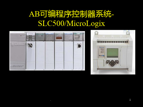
AB可编程序控制器系统SLC500/MicroLogix
.
1
关于罗克韦尔
罗克韦尔品牌包括艾伦–布拉德利Allen-Bradley的控制产品和工程 服务、道奇品牌的机械动力传输产品、瑞恩电气Reliance
Electric™制造的电机和驱动产品以及罗克韦尔软件Rockwell Software生产的工控软件。 罗克韦尔总部位于美国威斯康星州的密尔沃基市。公司通过提供
第2章 可编程序控制器处理器及 I/O模块
处理器运行/故障(绿/红)指示器灯“PROC”:
显示处理器当前的工作情况
灯(绿)亮:表示运行正常
灯(红)亮:表示处理器故障
强制指示灯 “FORCE”:显示用户有无强制I/O。
灯亮 :表示被强制
输入强制:用户强制输入数据文件中的位;
输出强制:能使用户强制实际的输出模板而
使用钥匙是为了在调试完毕后使处理器固定 在运行状态,防止程序被意外修改。
.
6
第2章 可编程序控制器处理器及 I/O模块
(2).指示灯
电池指示灯“BATT”:
灯(红)亮表示电池盒里的电池该更换了。一 般该指示灯亮后,应在10天内及时更换电池 ,否则可能因CMOS RAM的失效而造成程序 的丢失。
ABPLC培训85页

PPT文档演模板
ABPLC培训85页
第八章 EtherNet 网络通讯
通过EtherNet/IP 网络下载和联机 通过EtherNet/IP网络与1756 I/O 的通信 通过EtherNet/IP网络与R sView32通信
1756-OB32接线图
现场
PLC 输出隔离继电器
PPT文档演模板
ABPLC培训85页
1756-IF8(隔离式电压/电流模拟量输入模块)
差分模式—4通道
在IN-x和iRTN-x之间有一个249欧姆的 电流环电阻
PPT文档演模板
ABPLC培训85页
1756-IF8
差分模式—8通道
所有标有 iRTN 的连接端必须和 RTN 相 连
PPT文档演模板
ABPLC培训85页
第九章 ControlNet 网络通信
通过ControNet 网络下载与联机 通过ControlNet 网络与1756 I/O 通信 通过ControlNet 网络与R sView32 通信
PPT文档演模板
ABPLC培训85页
第十章 应用实例
通过RSNetWorx 进行硬件组态 通过RSLinx 进行通讯驱动配置 通过RSView32 进行上位机组态画面 通过RsLogix5000 进行I/O 组态及控制程序编程
KM1 KM2 KM3 KM2 KM1 KM3 KM3 KM1 KM2
PPT文档演模板
ABPLC培训85页
Example 1
PPT文档演模板
ABPLC培训85页
用Logix5000开发一个项目
新建一个工程 更改工程属性 I/O 组态 创建标签 编辑梯形图 下载工程
GuardLogix AB安全PLC基础学习资料
– 当结果被核实完毕后,并且OK,那么安全 输出数据被发送到安全输出
版权© 2008罗克韦尔自动化公司。保留所有权利。
14
RSLogix 5000的显性安全环境
安全控制器状态
安全指令面板
周期型安全任务
带类信息的例程 消息框
安全编辑屏幕的 水印
版权© 2008罗克韦尔自动化公司。保留所有权利。 15
版权© 2008罗克韦尔自动化公司。保留所有权利。
17
What safety certified application instructions do
• 这是认证的E Stop指令
•
提供与下列逻辑相同的功能:
– 16行梯级的逻辑
• • • •
• 结果
2个定时器 5个锁存线圈 3个一次脉冲 复杂的胶连逻辑
版权© 2008罗克韦尔自动化公司。保留所有权利。
一个平台执行所有功能
• 在一个控制器中实现标准控制和安全控制 • 标准控制器和安全控制器可位于通用的机架中 • 在通用网络上实现标准控制和安全控制
版权© 2008罗克韦尔自动化公司。保留所有权利。
7
ControlLogix安全完整性
GuardLogix
– 3条抑制指令 (光幕)
• 2传感器对称抑制 • 2传感器非对称抑制 • 4传感器双向抑制
– 安全地毯 – 可组态的安全继电器 – 8位置模式开关
版权© 2008罗克韦尔自动化公司。保留所有权利。
19
GuardLogix SIL 3安全任务
• 安全任务可以运行在下列2种状态之一
– 标准行为 (安全签名不存在) – SIL 3 安全行为 (安全签名存在)
•
安全任务 – 标准
RockwellABPLC基础培训入门篇
Rockwell AB PLC 基础培训入门篇,7天熟悉AB PLC系统开发第一篇AB的PLC产品长期以来一直被认为最可靠、最高端的PLC产品,产品的质量和性能为世界顶级,AB品牌属于美国ROCKWELL公司,其生产的PLC2(可能很多人并不知道,P LC5知道的人很多,在之前还有PLC2,PLC3产品)产品目前在世界上仍然有很多地方继续在工作。
AB的PLC大致可以分如下几类:1.Logix平台产品,细分如下:ControlLogix、CompactLogix、FlexLogix该系列产品全部采用Logix5000软件进行编程组态2.SLC500平台产品SLC500、MicroLogix该系列产品全部采用Logix500软件进行编程组态3.PLC5,PLC3,PLC2等老产品PLC5采用RsLogix5软件进行编程组态,某些老的型号采用DOS版6200软件进行编程PLC3,PLC2采用DOS版6200软件进行编程组态其中PLC2有几款第3方开发的编程软件,全运行在DOS环境下由于PLC5等产品非目前主流产品,正在逐步被淘汰,因此本文不将其作为讨论的主要内容。
RsLinx技术介绍:RsLinx软件为ROCKWELL产品提供了统一的通讯平台,是进行编程的必要软件之一。
RsLinx软件根据六个版本分为:RSLinx Lite、RSLinx Single Node、RSLinx OEM、RSLinx P rofessional、RSLinx Gateway、RSLinx SDK。
版本在RSLinx OEM以后的4个版本均支持开发OPC应用程序或C-API客户程序,并在RSLinx S DK中包括了开发OPC应用程序或C-API客户程序的技术资料。
标准版,Lite版本,此版本为免费版本,仅支持PLC编程通讯专业版,Professional版本,提供了OPC DDE SERVER功能,可以作为组态软件的通讯驱动,并且支持RSLINX C API开发的应用程序或驱动OEM版,单节点版,很少见,名如其意,也能支持OPC DDE SERVER网关版,Gateway版本,比专业版本增加了Remote 远程访问的能力,如远程OPC等。
Rockwell-AB-PLC-基础培训入门篇
Rockwell AB PLC 基础培训入门篇,7天熟悉AB PLC系统开发第一篇AB的PLC产品长期以来一直被认为最可靠、最高端的PLC产品,产品的质量和性能为世界顶级,AB品牌属于美国ROCKWELL公司,其生产的PLC2(可能很多人并不知道,P LC5知道的人很多,在之前还有PLC2,PLC3产品)产品目前在世界上仍然有很多地方继续在工作。
AB的PLC大致可以分如下几类:1.Logix平台产品,细分如下:ControlLogix、CompactLogix、FlexLogix该系列产品全部采用Logix5000软件进行编程组态2.SLC500平台产品SLC500、MicroLogix该系列产品全部采用Logix500软件进行编程组态3.PLC5,PLC3,PLC2等老产品PLC5采用RsLogix5软件进行编程组态,某些老的型号采用DOS版6200软件进行编程PLC3,PLC2采用DOS版6200软件进行编程组态其中PLC2有几款第3方开发的编程软件,全运行在DOS环境下由于PLC5等产品非目前主流产品,正在逐步被淘汰,因此本文不将其作为讨论的主要内容。
RsLinx技术介绍:RsLinx软件为ROCKWELL产品提供了统一的通讯平台,是进行编程的必要软件之一。
RsLinx软件根据六个版本分为:RSLinx Lite、RSLinx Single Node、RSLinx OEM、RSLinx P rofessional、RSLinx Gateway、RSLinx SDK。
版本在RSLinx OEM以后的4个版本均支持开发OPC应用程序或C-API客户程序,并在RSLinx S DK中包括了开发OPC应用程序或C-API客户程序的技术资料。
标准版,Lite版本,此版本为免费版本,仅支持PLC编程通讯专业版,Professional版本,提供了OPC DDE SERVER功能,可以作为组态软件的通讯驱动,并且支持RSLINX C API开发的应用程序或驱动OEM版,单节点版,很少见,名如其意,也能支持OPC DDE SERVER网关版,Gateway版本,比专业版本增加了Remote 远程访问的能力,如远程OPC等。
AB_PLC_入门培训
罗克韦尔公司Logix5000系列控制器编程入门指导AB PLC培训教程一AB PLC系统介绍1、AB PLC的系统结构2、AB PLC的组成部件3、AB PLC的各种文件4、AB PLC的运行模式5、周期任务、连续任务6、外部输入输出的地址格式二、编程软件的使用方法1、AB PLC软件分类2、AB软件的安装3、硬件组态与参数设置4、项目的管理5、程序的编辑三、建立在线连接1、安装RSLinx软件2、首次建立通讯3、建立以太网通讯4、连接在线5、强制变量一、AB PLC介绍1、1AB PLC系统结构最新一代的AB Logix5000系列PLC在一些手册上又称作控制器(Controller);这表示Logix5000系列PLC与传统SLC 500系列的PLC存在一些差异。
这些差异主要表现在编程软件、内部程序元素、通讯机制等方面。
1、2AB PLC的组成部件这里以现场使用的ControlLogix 5000为例说明;与西门子PLC类似,ControlLogix 5000的组成部件也主要可以有:CPU模块、电源模块、通讯模块、数字量输入/输出模块、模拟量输入/输出模块、高速计数器模块等。
通常还有一个安装这些部件的背板,背板上有不同的物理槽位。
与西门子PLC不同的是ControlLogix 5000系列的控制器CPU模块可以安装不同的位置。
1、3AB PLC中的数据文件在ControlLogix5000系列的PLC中具有各种不同类型的指令,不同的指令需要操作不同的文件类型。
AB PLC的资源和控制器状态通过数据文件描述,数据文件通过各种数据类型来表示。
数据文件的建立是通过在控制器的内存区域建立标签TAG。
数据块标签分为全局数据域文件和程序数据域文件。
全局数据文件:全局数据文件标签TAG具有控制器作用域,可以在所有的用户程序中使用。
输入输出数据文件是全局数据文件。
程序数据域文件:在程序中建立的程序标签TAG具有局部作用域,只能在当前的程序中使用。
ABPLC培训课件

04
ABPLC实践案例与技巧
电机控制案例及实现过程
电机控制概述
电机控制方案设计
电机控制是一种使用电力驱动的控制系统, 用于控制电机的速度、位置和转矩等。
针对不同类型的电机,如直流电机、交流电 机等,设计不同的控制方案,包括调速、正 反转、位置控制等。
硬件配置与选型
软件实现
根据控制方案,选择合适的PLC、变频器、 编码器等硬件设备,并确定其型号、规格和 参数。
1 2
通信故障
检查通信协议、端口设置、网络连接等是否正 确。
输入输出故障
检查输入输出模块、连接线、扩展单元等是否 正常。
系统故障
3
重启PLC、检查电源、更换故障硬件等。
PLC维护保养及安全注意事项
保持环境整洁
避免灰尘、电磁干扰和潮湿等。
软件维护
更新和修复软件漏洞,保证PLC系统的稳定 性。
定期检查硬件
输入/输出(I/O)模块及使用
总结词
ABPLC的输入/输出(I/O)模块是用于数据采集和设备控制的关键组件。
详细描述
ABPLC的I/O模块有多种类型和规格,可以根据不同的应用场景选择合适的模块。例如,模拟量输入模块可以 采集连续的电压或电流信号,而数字量输入模块则可以接收开关量信号。输出模块则可以根据控制要求将PLC 的指令输出到相应的设备上。
应用技巧
掌握PLC的逻辑控制原理,熟悉控 制流程和程序结构,积累经验并善 于总结。
06
ABPLC未来发展及新技术应用
ABPLC在工业互联网中的应用前景
工业互联网的快速发展
随着工业互联网的快速发展,ABPLC作为关键技术之一,将有更广泛的应用前景。
工业互联网平台建设
ABPLC培训85页
第四章 梯形图设计(shèjì)方法〔 ***〕
• 阅历(yuèlì)设计法 • 由继电器电路图到梯形图
第五页,共84页。
第五章 PLC 网络(wǎngluò)组态
• A-B PLC 网络概述 • RsNetworx 软件(ruǎn jiàn)运用
第六页,共84页。
第六章 PLC通讯(tōngxùn)与自动化通 讯(tōngxùn)网络
第四十二页,共84页。
由继电器图到梯形图
• 了解和熟习被控设备的工艺进程和机械的义务状况,依据继电器电 路图剖析和掌握(zhǎngwò)控制系统的义务原理。
• 确定PLC的输入信号和输入负载,以及与他们对应的梯形图中的输入 位和输入位的地址,划出可编程控制器的外部接线图。
• 确定与继电器电路图中的中间继电器,时间继电器对应的梯形图中 的中间点和定时器。
ON POWER
OFF 电源开关
L1
L2/N
勇于开始,才能找到成功的路
L1,L2 为 AC220V 交流电压输入
第二十一页,共84页。
1756-CNBR
reversion A B ok
模块状态文字 显示
模块状态显示 勇于开始,才能找到成功的路
通道状态显示
第二十二页,共84页。
通道A的连接口 通道B的连接口
第十二页,共84页。
可编程控制器的展开(zhǎn kāi)
• 如今已有第五代PLC产品 • 在八十年代至九十年代中期,是PLC展开最快的时期,年增长率
才干和网络方面功用的提高,挤占了一局部DCS的市场〔进程控 是由于工业PC〔IPC〕的出现,特别是近年来现场总线技术的展开 年来PLC增长速度总的说是渐缓。目前全世界有200多厂家消费3 粮食加工〔16.4%〕、化学/制药〔14.6%〕、金属/矿山〔11.5%〕 行业PLC逐渐显示出了其他产品不可替代的优势
AB PLC CompactLogix体验培训
AB PLC CompactLogix体验培训CompactLogix 基础实验◆Lab 1:创建新的处理器程序,组态I/O-----------------------------------------------------------P3⏹打开RSLogix 5000程序⏹RSLogix 5000程序菜单和项目树讲解⏹编辑主例程(交通灯控制程序)⏹检查主任务和主程序⏹组态I/O⏹组态离散量I/O的混合模块⏹观察Tag◆Lab 2:建立通讯,下载程序,建立新任务、新程序----------------------------------------------P16⏹打开RSLinx程序⏹建立RS232-DF1驱动⏹创建新的周期任务⏹创建新的程序⏹创建新的例程⏹创建计数器CompactLogix网络试验◆Lab 3:控制EtherNet/IP网络上Point I/O-------------------------------------------------------P31⏹创建一个L35E项目⏹添加远程1734 Point I/O 以太网适配器及I/O模块⏹添加逻辑程序,下载项目并测试◆Lab 4:控制EtherNet/IP网络上PowerFlex变频器试验------------------------------------P45⏹创建一个CompactLogix项目⏹添加PowerFlex700变频器⏹观察RsLogix5000自动生成的对象数据模型,并构建别名标签⏹添加控制变频器的梯形程序⏹下载程序到L35E中并运行◆Lab 5:通过PanelView Plus触摸屏控制PowerFlex70变频器----------------------------P54⏹创建一个RSView ME 程序⏹建立通讯通道⏹创建监控画面并进行数据连接⏹编译项目并模拟运行◆Lab 6:通过EtherNet/IP 实现Producer/Consumer通讯-----------------------------------P62⏹创建一个CompactLogix项目⏹建立Producer标签程序⏹建立Consumer标签程序⏹测试通讯程序,实现CPU对时◆Option Lab 1:学习其他的编程语言--------------------------------------------------------------P80⏹创建顺序功能图⏹创建趋势图观察CTU的累加值⏹测试连续任务⏹测试周期任务◆Option Lab 2:可重用代码------------------------------------------------------------------------P96⏹打开两个应用⏹拷贝主程序,粘贴可重用代码⏹Map标签⏹测试重用代码CompactLogix 动手实验LAB 1. 创建一个新的控制器文件,组态I/O在这个实验里,您将:⏹创建一个新的控制器文件⏹用符号标签名编写梯形图逻辑⏹组态I/O模块⏹将您在梯形图逻辑中创建的标签指向模块标签◆打开RSLogix 5000编程软件在实验的这一部分,打开RSLogix 5000编程软件,您就可以对DEMO箱中的处理器进行编程。
(2024年)《ABPLC学习入门》PPT课件

03
RSLogix5000还提供了丰富的库函数和工具,方便用户 快速构建复杂的控制系统。
17
梯形图编程方法
梯形图是一种图形化编程语言, 通过绘制电路图形式的程序来表
达控制逻辑。
在RSLogix5000中,用户可以 使用内置的梯形图元件库,通过
拖拽和连接元件来构建程序。
梯形图编程具有直观、易懂的优 点,适用于简单的逻辑控制和顺
序控制。
2024/3/26
18
顺序功能图编程方法
顺序功能图是一种描述控制系统行为的语言,通过状态和状态之间的转移来表达控 制逻辑。
在RSLogix5000中,用户可以使用内置的顺序功能图元件库,通过绘制状态图和设 置状态转移条件来构建程序。
2024/3/26
顺序功能图编程适用于复杂的逻辑控制和顺序控制,具有结构清晰、易于维护的优 点。
29
2024/3/26
谢谢聆听
30
发出报警信号。
2024/3/26
27
压力控制应用实例
2024/3/26
压力检测与显示
01
通过ABPLC的模拟量输入模块读取压力传感器信号,实时显示
当前压力值。
压力设定与控制
02
利用ABPLC的数字量输入/输出模块,实现对压力设定值的输入
和控制输出,保持压力恒定在设定值附近。
压力报警功能
03
在ABPLC程序中加入压力报警功能,当压力超过设定范围时及
《ABPLC学习入门 》PPT课件
2024/3/26
1
目录
2024/3/26
• ABPLC概述 • ABPLC基础知识 • ABPLC硬件组成 • ABPLC软件编程 • ABPLC通讯技术 • ABPLC应用实例
(2024年)abplc基础教程ppt教学课件

记录每次维护保养的执行情况,包括更换 的部件、清洗的部位、维护的时间等,以 便后续跟踪和分析。
故障预警机制
维护保养知识库
建立故障预警机制,通过对PLC运行数据的 实时监测和分析,及时发现潜在的故障隐 患并采取相应的措施。
建立维护保养知识库,收集和整理PLC的维 护保养经验、技巧和案例,为后续的维护 保养工作提供参考和借鉴。
abplc基础教程ppt教 学课件
2024/3/26
1
目录
2024/3/26
• ABPLC概述与基本原理 • 硬件组成与选型指导 • 软件编程环境与操作指南 • 通讯协议与网络技术解析 • 故障诊断与维护保养策略制定 • 实战项目:基于ABPLC的控制系统设计实
现
2
CHAPTER 01
ABPLC概述与基本原理
软件安装步骤
下载最新版本的abplc编程软件安装包;
双击安装包,按照提示完成软件的安装过程;
2024/3/26
12
编程软并进行初始设置。
2024/3/26
02
软件界面组成
菜单栏:包含文件、编辑、视图、工具、窗口和帮助等菜单项
03 ;
13
编程软件安装及界面介绍
网络搭建
按照选定的网络拓扑结构进行 布线、配置IP地址等网络设置 。
测试与调试
对整个通讯网络进行测试和调 试,确保数据传输的准确性和 实时性。
28
CHAPTER 05
故障诊断与维护保养策略制 定
2024/3/26
29
常见故障类型及原因分析
01
电源故障
由于电源线路短路、过载或电源模 块损坏等原因导致。
确保目标设备连接正常 且通讯参数设置正确;
AB CompactLogix PLC 基础培训
BGRIMM AB PLC 培训CompactLogix系列王俊鹏2010-2-23[在此处键入文档的摘要。
摘要通常是对文档内容的简短总结。
在此处键入文档的摘要。
摘要通常是对文档内容的简短总结。
]目录1 AB Logix系列控制器类型简介 (1)1.1 ControlLogix控制器 (1)1.2 CompactLogix控制器 (2)1.3 FlexLogix控制器 (2)1.4 SoftLogix控制器 (3)1.5 DriveLogix控制器 (3)2 CompactLogix硬件介绍 (3)2.1 基本系统组成 (4)2.2 控制器 (4)2.3 分组扩展 (4)2.4 电源模块的安装和选择 (5)2.5 I/O模块的安装位置 (5)2.6 CF卡 (6)2.7 后备电池 (6)2.8 编程接口 (6)3 常用的操作 (7)3.1 需要用到的软件 (7)3.2 使用BootP-DHCP Server配置PLC的IP地址 (7)3.3 使用RSLinx建立起计算机与PLC的链接 (10)3.4 升级PLC模块的固件软件(firmware) (13)3.4.1 使用ControlFlash升级Firmware (13)3.4.2 用CF卡升级Firmware (16)3.5 下载程序到PLC (16)3.5.1 将程序下载到RAM中去 (16)3.5.2 用非易失性存储器保存程序 (18)4 RSLogix5000编程软件 (20)4.1 项目管理器介绍 (20)4.2 编程语言 (21)4.3 任务 (21)4.4 数据文件 (21)4.5 故障记录的清除 (21)4.6 梯形图编程方法与一般规则 (23)1AB Logix系列控制器类型简介Rockwell自动化Logix平台提供了单一的集成化控制机构,能够实现离散、传动、运动以及过程控制。
这种集成式的Logix控制架构提供了通用的控制引型、软件编程环境和跨多硬件平台的通讯支持。
《ABplc培训教程》PPT课件
通过具体案例详细讲解功能块图的编程方法和技巧,包括如何选择合适的图形符号、如何 设置元素参数和属性、如何优化程序结构等。同时提供完整的程序代码和注释说明供读者 参考和学习。
05
ABplc高级编程技能
结构化文本(ST)编程技巧
01
02
03
04
熟练掌握ST语言基本语 法和规则
能够使用ST语言进行复 杂逻辑运算和数据处理
发展历程
自1969年推出第一款PLC以来,ABplc不断发展和创新,逐渐成为工业自动化 领域的重要控制设备之一。
ABplc应用领域
01
02
03
04
工业自动化
ABplc广泛应用于各种工业自 动化生产线和设备中,如机床 、包装机械、印刷机械等。
能源管理
在电力、石油、天然气等能源 管理领域,ABplc可实现能源
现场总线接口
如Profibus、DeviceNet等, 用于与现场设备通信,实现分 布式控制系统。
无线通讯接口
支持无线通信标准,如Wi-Fi、 蓝牙等,实现无线数据传输和 远程控制。
03
ABplc软件编程环境
软件安装与启动
安装步骤 下载ABplc编程软件安装包;
双击安装包,按照提示进行安装;
软件安装与启动
顺序控制程序包括多种编程元素,如 指令、定时器、计数器、跳转等。
功能块图(FBD)编程实例
功能块图介绍
功能块图是一种图形化编程语言,用图形符号表示程序中的各个元素和它们之间的逻辑关 系。
编程步骤
首先创建功能块图程序文件,然后添加所需的输入/输出变量和内部变量,接着绘制功能 块图并设置各个元素的参数和属性,最后进行编译和下载到PLC中。
AB PLC ControlLogix系统基础培训手册
((((ControlLogix 基础培训手册罗克韦尔自动化自动控制及信息产品集团中国.济南ControlLogix基础培训手册目录1 常用工具1.1 通讯管理工具RSLinx1.2 模块升级工具ControlFLASH2 ControlLogix编程指南2.1 ControlLogix平台简介2.2 Logix5000编程软件快速入门2.2.1 安装控制器2.2.2 创建及下载工程2.2.2.1 创建工程2.2.2.2 添加模块2.2.2.3 改变模块属性2.2.2.4 查看I/O2.2.2.5 创建标签(Tag)2.2.2.6 利用别名标签(Alias Tag)记录I/O2.2.2.7 输入梯形图程序2.2.2.8 下载工程2.2.3 查看程序扫描时间2.2.4 查看控制器内存使用情况2.3 梯形图常用指令2.4 功能块图编程与过程控制1 常用工具1.1 通讯管理工具RSLinxRSLinx是罗克韦尔自动化公司为用户提供的通讯管理软件,它运行在Windows操作系统的计算机上。
用户只需选择一种从该计算机到工业控制网络上任一模块的通讯方式,就可以通过该软件建立起与工业控制网络上所有设备的通讯。
RSLinx操作举例(计算机到Logix处理器为串口连接):1) 用户选择从计算机到网络的通讯方式:串口方式2) 用户检查计算机上相关通讯卡是否已经安装,连接电缆是否正确:使用1756-CP3连接计算机和处理器。
3) 点击RSLinx“communication(通讯)”下拉菜单中的“Configure Drivers(配置驱动方式)”选项。
4) 在“available drivers(可用驱动方式)”中选择“RS-232DF1 devices”,再点击“add new”选项,并选择OK。
5) 在弹出的“Configure RS-232 DF1 devices”菜单中点击“auto-configure(自动配置)”,等待运行结果后选择OK。
ABPLC配置培训教材
第12页/共51页
RSLinx Classic软件打开后显示如下:
第13页/共51页
点击Configure Drivers图标
第14页/共51页
点击后跳出如下对话框
第15页/共51页
在下拉列表中选择Ethernet devices
第38页/共51页
为使DeviceNet设备能够正确运行,需要在RSNetworx注册EDS文件。
依次点击Tools-EDS Wizard,弹出右侧对话框。
第39页/共51页
按照红框进行操作
注意:设备的EDS文件在每台电脑上只需要注册一次即可。
第40页/共51页
以1734-AND配置举例
第41页/共51页
第28页/共51页
选择OK或apply,把配置好的信息下载到DNB
注意:此时处理器的状态必须在Program或Remote Program模式下
第29页/共51页
依次点击开始-程序-Rockwell Software-RSLogix 5000 Enterprise-RSLogix 5000
第30页/共51页
PLC框架
关于存储器:我们只需要关心哪一些是输入变量,哪一些是输出变量,那么其他的肯定都是中间变量。
第1页/共51页
以AB PLC为例来说,把分布式I/O和现场I/O作为输入输出模块,比如Siemens的ET200s、AB的1734-AND、1791DS-IB8XOB8等。PLC通过DeviceNet网络扫描这些模块的输入点或者把输出量送到模块的输出点。这些点在程序中对应的变量如图(举例):
第7页/共ห้องสมุดไป่ตู้1页
abplc培训教程

块与/块或指令,用于实现多个条件的组合逻辑。
MPS/MRD/MPP
多点设定/多点读取/多点处理指令,用于实现复杂程序 流程的控制。
程序结构设计与优化
程序结构设计原则
清晰、简洁、易于理解和维护。
模块化设计
将程序划分为多个功能模块,每个模 块实现特定的功能,提高程序的可读 性和可维护性。
优化程序结构
减少程序中的重复代码,提高程序的 执行效率。
使用跳转指令和子程序
简化程序结构,提高程序的灵活性和 可重用性。
常用功能块使用说明
01
02
03
04
定时器功能块
实现定时控制功能,如延时启 动、定时关闭等。
计数器功能块
实现计数控制功能,如产品计 数、故障次数统计等。
数据处理功能块
实现数据的比较、运算、转换 等功能,如加减乘除、数据格
理(与、或、非等)的方法。
数据比较与排序
03
了解如何在AB PLC中实现对数据的比较和排序操作,以满足不
同控制需求。
顺序控制功能实现
顺序控制基本概念
掌握顺序控制的基本原理和常用术语,如状态、转移条件、动作 等。
顺序控制程序设计
学习使用AB PLC的编程语言(如Ladder Logic、Structured Text等)进行顺序控制程序的设计和实现。
顺序控制优化与调试
了解如何优化顺序控制程序,提高其执行效率和可靠性,并掌握 相应的调试技巧。
模拟量处理及PID控制
模拟量输入/输出处理
学习在AB PLC中处理模拟量输入/输出的方法,包括模拟量信号 的采集、转换和处理等。
PID控制原理与实现
掌握PID控制的基本原理和参数整定方法,了解如何在AB PLC中实 现PID控制算法。
ControLogix-标准课程
任务1
任务中断
任务2
任务3
5
10
15
20
25
30
35
40
45
50
时间单位 ms
• 所有的周期型任务和事件触发型任务都可以中断连续型任务。 • 高优先权任务中断所有的低优先权任务。 • 高优先权任务可多次中断低优先权任务。 • 同等级优先权的任务同时触发时各轮流执行1ms,交互进行。 • 当连续型任务完成全部扫描时,立即重新开始新的一轮扫描。
ControlLogix 系统概述(7)
ControlLoix 平台
电源指示 灯
框架
电源
I/O 和通讯模块
控制器
ControlLogix 系统概述(8)
ControlLoix 硬件基本结构
• 机架 4槽、7 槽、10槽、13槽、17槽 ,每个机架自供电源。
• 控制器模块 Logix5550 Logix5553 Logix5555 Logix556X
子程序
子程序是真正的执行, 所有的控制代码都被编写在子程序中,有四种编程 形式:
•
梯形图LD 最常采用的编程模式,是由梯级组成的程序结构,完成
逻辑时序控制的程序编辑。
•
顺序功能流程图SFC 将工作流程细化到步,用SFC来编辑步的执
行顺序和结构,而每个步都是执行代码的组成。
•
文本编程ST 采取ASCII代码编写程序,通常用于复杂或特殊要求
Logix5000 控制器的在线连接(3)
RSLinx® 组态软件
浏览窗口 自动刷新பைடு நூலகம்
选择背板
X
背板模块浏览
X
缺失或有问题的模块
Logix5000 控制器的在线连接(4)
- 1、下载文档前请自行甄别文档内容的完整性,平台不提供额外的编辑、内容补充、找答案等附加服务。
- 2、"仅部分预览"的文档,不可在线预览部分如存在完整性等问题,可反馈申请退款(可完整预览的文档不适用该条件!)。
- 3、如文档侵犯您的权益,请联系客服反馈,我们会尽快为您处理(人工客服工作时间:9:00-18:30)。
ControlLogix基础培训手册目录1常用工具1.1通讯管理工具RSLinx1.2模块升级工具ControlFLASH2ControlLogix编程指南2.1ControlLogix平台简介2.2Logix5000编程软件快速入门2.2.1安装控制器2.2.2创建及下载工程2.2.2.1创建工程2.2.2.2添加模块2.2.2.3改变模块属性2.2.2.4查看I/O2.2.2.5创建标签(Tag)2.2.2.6利用别名标签(Alias Tag)记录I/O2.2.2.7输入梯形图程序2.2.2.8下载工程2.2.3查看程序扫描时间2.2.4查看控制器内存使用情况2.3梯形图常用指令2.4功能块图编程与过程控制3ControlNet组态软件(RSNetworx for CN)3.1ControlNet基本知识3.2RSNetworx for CN操作步骤4DeviceNet组态软件(RSNetworx for DN)4.1DeviceNet基本知识4.2RSNetworx for DN操作步骤5流程监控软件RSView1常用工具1.1通讯管理工具RSLinxRSLinx是罗克韦尔自动化公司为用户提供的通讯管理软件,它运行在Windows操作系统的计算机上。
用户只需选择一种从该计算机到工业控制网络上任一模块的通讯方式,就可以通过该软件建立起与工业控制网络上所有设备的通讯。
RSLinx操作举例(计算机到Logix处理器为串口连接):1)用户选择从计算机到网络的通讯方式:串口方式2)用户检查计算机上相关通讯卡件是否已经安装,连接电缆是否正确:使用1756-CP3连接计算机和处理器。
3)点击RSLinx“communication(通讯)”下拉菜单中的“Configure Drivers(配置驱动方式)”选项。
4)在“available drivers(可用驱动方式)”中选择“RS-232 DF1 devices”,再点击“add new”选项,并选择OK。
5)在弹出的“Configure RS-232 DF1 devices”菜单中点击“auto-configure(自动配置)”,等待运行结果后选择OK。
6)点击RSLinx“communication(通讯)”下拉菜单中的“RSWho”选项,就会弹出整个工业控制网络的树状浏览画面(见下图)。
注:用户还可点击浏览画面中的“”,以进一步浏览其所延伸的网段。
7)1.2模块升级工具ControlFLASH:罗克韦尔自动化公司新一代控制平台中的大部分模块都是“内置微处理器+功能软件(firmware)”的智能模块,并且功能软件(firmware)均存储在可重复刷新的存储器中。
用户只需使用最新版本的ControlFLASH软件,对模块进行刷新即可实现模块升级,从而保证客户采购的模块在很长的使用时间内都能与新技术以及增强功能相适应。
ControlFLASH可单独运行在Windows操作系统的计算机上,也可内嵌在Logix5000控制编程软件中。
用户通过RSLinx建立起计算机到待升级模块的通讯通道后,即可运行该软件。
在软件中用户根据画面提示依次选择设备目录号、新的功能软件版本号(firmware revision)即可。
ControlFLASH操作举例(Logix5555处理器从版本10升级至版本11):1)准备工作:通过RSLinx建立起计算机到模块的串口通讯。
将处理器置于“Program(编程)”模式。
2)运行ControlFLASH软件,在主画面上选择“Next(下一步)”,在弹出窗口中选择相应处理器目录号。
3)按产品目录号选择相应模块后,点击“next(下一步)”弹出“Superwho”控制网络浏览窗口。
在该窗口中用户应按网络路径延伸并选择要刷新的模块。
4)点击“next(下一步)”弹出“Firmware Revision(功能软件版本)”选择窗口。
请选择相应版本号并点击“OK”。
5)如果有关刷新文件不在缺省安装目录中,将弹出“文件目录浏览窗口”以便用户选择文件所在目录,点击“OK”。
6)点击“next(下一步)”弹出“Summary”窗口。
用户点击“Finish”就会开始模块刷新处理。
注意事项:进行ControlFLASH操作前应停止控制系统的运行;如果对处理器进行升级,还需保证其应用程序已作备份;并且,在整个模块刷新过程中,不允许掉电或者通讯中断。
2ControlLogix编程指南2.1ControlLogix平台简介在过去,为了实现工厂自动化,工程师们往往不得不面对PLC、伺服控制器等多种自动化子系统,需要同时掌握多种专业化软硬件的开发和维护。
随着近年来自动化水平的不断普及和提高,这种情况越来越成为制约工厂发展的“瓶颈”问题:自动化设备越来越多、自动化技术越来越复杂,而工厂技术人员的精力和时间却相对有限。
因此,“使用单一控制平台实现全厂范围内的所有控制任务”成为广大用户的迫切要求。
借助电子、通信以及控制领域中不断发展的新技术,顺应这一要求,全球领先的罗克韦尔自动化公司提出了“全功能控制平台”的设计理念,并在此基础上发布了ControlLogix产品。
无论是高速离散控制、复杂过程控制、伺服控制,还是高速传动控制等各种应用,借助单一的ControlLogix平台,用户只需掌握一种编程软件,就能根据应用要求的不同,选择标准模块,选择标准工业网络/总线得到所需的控制系统,如顺控/安全连锁系统、伺服控制系统、分布式控制系统(DCS)、高速传动控制系统以及数据采集监控系统(SCADA)等。
ControlLogix平台不仅技术领先,而且在烟草、消费品制造、冶金、电力、石化、油气输送、造纸、水处理、地铁、矿山以及汽车等各个行业中都有许多成功的应用。
ControlLogix平台主要特点如下:所有模块均可带电插拔;用户通过软件刷新即可实现包括处理器在内的各种模块的升级;功能强大的Logix处理器o处理器具有高速程序及数据处理能力,1K指令仅需0.06毫秒;o单个处理器最多支持:128000开关量或4000模拟量。
o用户无需更换处理器,通过替换更大容量的内存即可扩充系统处理能力;o完全标签变量编程方式,采用动态内存管理技术,无需用户进行内存分配管理。
没有定时器/计数器等使用个数的强行限制,支持数据类型的自动转换。
o支持多维数组、标准数据结构及用户自定义数据结构。
创新的、最大可用性设计的机架和背板:使用制造者/消费者(Producer/ Consumer)技术的无源多主数据总线;o在同一机架中可多处理器并存,实现分布式运算;o在同一机架中可配置任意多个通讯模块,实现网络延伸和不同网络间路由;o无需处理器干预,现场输入信号(作为Producer tag)可以同时直接送给同一网络上的多个智能设备、处理器及服务器(作为Consumer tags)等,避免了传统的“现场信息先由主站存储再顺序转发”的过程,大大提供了通讯效率;o通过ControlNet扩展现场I/O。
在所有本地站和现场站中,对于每个输入输出模块都可以根据其实际应用的响应快慢的要求分别设置相应的通讯时间:逢变则报(COS)和按给定周期发送(RPI),保证了工业控制的实时性和确定性。
支持ControlNet、DeviceNet以及 FF H1等国际标准工业现场总线,兼容Hart过程仪表总线协议,同时提供与各类第三方控制系统的广泛接口。
支持开放的100Mbps EtherNet/IP网络,控制系统和上位机可以组成完全意义的多服务器/多客户机模式的实时监控系统。
在EtherNet/IP、ControlNet和DeviceNet各层网络中采用统一的CIP协议,该协议实现了对实时控制数据和非实时监视/组态数据的区别对待,保证了工业控制的实时性和确定性;同时,也保证了系统中各层设备对象定义的统一、网络服务的统一,实现了不同网络间数据的完全透明,也保证了用户只需一次培训就可建立起对于EtherNet/IP、ControlNet或DeviceNet不同网络上设备通讯功能的完整认识。
所有模块,包括I/O模块均为智能化模块:o输入输出模块提供断线等各类诊断功能,并可提供时间标记;所有以上数据都被该模块自动生成标签变量,可被程序直接引用;o模拟量输入输出模块在模块本身即可实现工程单位转换、高/低以及高高/低低报警运算,并被该模块自动生成标签变量,可被程序直接引用;o提供带电子熔断保护功能的开关量输出模块,回路在短路故障排除后通过软件复位即可恢复,无需设置/更换保险丝。
2.2Logix5000编程软件快速入门2.3梯形图常用指令字符串处理指令字符串比较(见前述比较指令部分:等于EQU、不等于NEQ、大于GRT、大于等于GEQ、小于LES、小于等于LEQ、表达式比较CMP)STOD - String to DINT conversion (ACI)DTOS - DINT to String conversion (AIC)STOR - String to Real conversionRTOS - Real to String conversionCONCAT - String concatenate (ACN)MID - String middle extract (AEX)FIND - String search (ASC)DELETE - String deleteINSERT - String InsertLEFT、RIGHT、MID、LOWER、UPPER、REPEAT ASCII串口操作指令ACL – ASCII Clear Receive and/or Send BufferACB – ASCII Number of characters in bufferABL – ASCII Test for Buffer LineAHL – ASCII Handshake LineARD – ASCII ReadARL – ASCII Read LineAWA – ASCII Write with appendAWT – ASCII Write此外还有超过30条专用伺服控制指令3ControlNet组态软件(RSNetworx for CN)3.1ControlNet基本知识作为IEC61158国际标准的高速工业现场总线,ControlNet是一种面向实时控制进行优化设计的网络,特别适合于有严格实时控制要求的场合。
开放、高速、确定和可重复性是它的主要特点。
5Mbps的数据传输率不会随网络距离延伸而衰减,通过同轴电缆可达6KM(通过光纤延伸可达30KM)。
并且,ControlNet提供冗余网络和本安型网络供用户根据需要进行选择。
