流道设计
离心风机流道设计及优化研究

离心风机流道设计及优化研究离心风机是目前常见的一种用于通风、排风、送风等工程领域的设备,其核心部件——流道设计和优化,对于风机的性能和效率具有重要影响。
在本文中,将探讨离心风机流道设计及优化的相关内容,并介绍一些常见的优化方法和技术。
一、离心风机流道设计的重要性在离心风机中,流道是将进入的气体引导并加速到风机出口的关键部分,其设计直接影响到风机的性能和效率。
合理的流道设计能够改善气体的流动情况,提高风机的压力能力和送风量,从而达到更高的效率和能耗降低。
而不合理的流道设计可能会导致流动不均匀、能量损失过多等问题,降低风机的性能。
二、离心风机流道设计的要点1. 流道截面设计:离心风机的流道截面形状对于气体流动的扩张和压力变化起着重要作用。
合理的截面设计应考虑流体的流动特性和气体性质,使得气体能够顺利地通过截面,避免过度扩张和收缩,从而减少气流的阻力和能量损失。
2. 纵向流道设计:纵向流道的设计主要考虑气流的加速和扩张,在保持流态稳定的前提下,提高风机的压力能力。
通过合理的纵向流道设计,可以使气流在流道内部能够顺利加速,并尽量减少阻力和湍流的产生,从而最大程度地提高离心风机的效率。
3. 流道表面光滑度:流道表面的光滑度对气流的流动阻力和损耗有着重要影响。
光滑的表面能够减少摩擦阻力,提高流道的效率。
因此,在流道设计中,应注意流道表面的加工工艺和涂层材料的选用,以保证流道表面的光滑度和微粗糙度控制在合理范围内。
三、离心风机流道优化的方法和技术1. 数值模拟与仿真:利用计算流体力学(CFD)方法,对离心风机的流场进行数值模拟和仿真分析,可以得到流道内气流的速度、压力等分布情况,进而评估不同设计方案的性能。
这种方法不仅能够快速进行流道设计的优化,还能够为流道的改进提供有效的思路和参考。
2. 正交试验设计:利用正交试验设计方法,对流道的关键参数进行多因素、多水平的试验,以寻找最佳的参数组合,优化流道设计。
通过实验数据的统计分析,可以确定不同参数对流场的影响程度和相互关系,为进一步的优化提供依据。
点浇口流道设计标准
点浇口流道设计标准点浇口流道设计是指在混凝土浇注过程中,在构件表面设置特定形状的沟槽,用于引导和控制混凝土流动。
点浇口流道设计的目的是保证浇注过程中混凝土能够均匀流动,并且确保构件表面不会产生堆积或漏浆现象。
下面是点浇口流道设计的一些标准和要求:1. 点浇口流道的形状应该是圆弧形或者椭圆形,这样能够有效地控制混凝土的流动,减少流速和冲击力,避免产生分层或者空洞等缺陷。
2. 点浇口流道的宽度要根据混凝土的流动性进行合理设计。
一般来说,流动性较好的混凝土,流道的宽度可以适当减小。
相反,流动性较差的混凝土,流道的宽度则需要适当增大。
3. 点浇口流道的深度应该根据浇注厚度和混凝土的性质来确定。
在混凝土浇注时,流道的深度要与浇注层的厚度保持一定比例。
一般来说,流道的深度可以略大于浇注层的厚度。
4. 点浇口流道的间距要根据浇筑施工的需要来确定。
一般来说,流道之间的间距可以根据施工的步骤和设备的要求来决定。
比如,如果使用振动器进行浇筑,流道之间的间距可以适当增大。
5. 点浇口流道的几何形状要符合混凝土浇筑施工的要求。
一般来说,流道的几何形状应该简单,造型规整,确保在浇筑过程中混凝土能够顺利流动。
6. 点浇口流道设置的位置要考虑结构的承重和抗震要求。
一般来说,流道的位置应该远离结构的边缘和受力部位,以避免影响结构的强度和稳定性。
综上所述,点浇口流道设计标准主要关注流道的形状、宽度、深度、间距、几何形状和位置等方面。
通过合理的设计和施工,能够保证混凝土在浇筑过程中的均匀流动,最大程度地避免产生缺陷。
同时也能够提高施工效率,减少浪费,保证结构的质量和安全。
2_05浇口和流道设计

2_05浇口和流道设计浇口和流道设计是塑料注塑成型过程中非常重要的一环,它们的设计质量直接关系到成型件的质量和生产过程的稳定性。
本文将详细介绍浇口和流道设计的意义、原则以及一些常见的设计方法。
一、浇口的设计意义1.提供熔融塑料进入模具腔体的通道,确保塑料充填腔体均匀;2.控制塑料进入速度和压力,避免短充、气泡等缺陷;3.有效防止熔融塑料对模具磨损和腐蚀;4.方便脱模和切除浇口处余料。
二、浇口设计的原则1.浇口位置应选择在产品外表面影响不大的部位,如底部、壁角等;2.浇口形状应简单,避免锐角和复杂几何形状,以利于塑料顺利进入腔体;3.浇口尺寸应合理,既能保证塑料充填,又不至于过大过长造成浪费和废料;4.浇口和产品分离的方式应考虑生产效率和产品外观要求;5.浇口设计要充分考虑熔融塑料的物理性质和流动性,避免局部过热或过冷。
三、流道设计的意义1.将浇注的熔融塑料传递到各个腔体,使得产品充填均匀;2.控制塑料的流速和压力,避免气泡、短充等缺陷;3.提供相对稳定的压力和温度环境,促进熔融塑料的密度均匀;4.对于多腔体模具,流道设计还要充分考虑产品产量的平衡。
四、流道设计的原则1.流道的直径、长度和截面积要合理选择,以保证塑料在流道内的流速符合流动性要求;2.流道和浇口的连接处要能够顺利过渡,避免过渡断面过小或过大造成流动不畅;3.流道的布置应考虑与模具结构的配合,以便于流道的加工和安装;4.尽量减少流道的弯曲和分支,以减小塑料流动阻力和热量损失;5.流道的表面要光滑,减小摩擦阻力和物料附着。
总之,浇口和流道设计是塑料注塑成型过程中关键的一环,其设计质量直接影响产品的质量和生产过程的稳定性。
合理的浇口和流道设计可以确保塑料充填均匀、避免气泡和短充等缺陷,并提高生产效率和降低生产成本。
因此,在进行浇口和流道设计时,需要综合考虑材料的流动性能、产品的几何形状、模具结构等因素,并遵循一定的设计原则。
梯形流道设计标准
关于梯形流道设计的标准通常是根据具体的工程需求和国家/地区的规范来制定的。
梯形流道是一种用于引导流体(液体或气体)的结构,其横截面呈梯形形状。
以下是一些可能与梯形流道设计相关的一般性标准和原则:
1. 流体力学原理:设计梯形流道时,需要考虑流体力学原理,确保流体在流道内的流动是稳定、均匀且符合设计要求的。
2. 流体性质:考虑流体的性质,如密度、粘度等,以便正确计算流体的流动特性。
3. 材料和结构设计:流道的材料选择和结构设计应满足工程的要求,包括强度、耐久性和抗腐蚀性。
4. 尺寸和几何形状:流道的尺寸和几何形状应根据具体的工程要求和流体流动特性进行合理的选择。
这可能涉及到流道的宽度、深度、横截面形状等参数的确定。
5. 入口和出口设计:流道的入口和出口设计对于确保流体的平稳进入和离开流道至关重要。
这包括减小流体的速度梯度,以防止湍流和能量损失。
6. 防堵塞设计:对于一些特殊应用,需要考虑防止流道堵塞的设计,以确保流体能够顺畅流动。
7. 维护和清理:考虑到维护和清理的需要,设计应当方便检修和清理,以确保流道在使用过程中能够保持高效运行。
请注意,具体的梯形流道设计标准可能因国家、行业和具体工程要求而异。
因此,在进行梯形流道设计时,最好参考相关的国家或地区的工程规范和标准,并确保符合相应的法规和安全要求。
流道设计规则
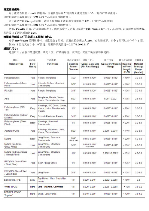
流道直径规则:
对于流动性较差(hard)的材料,流道长度每隔3”需要加大流道直径1/32。
(包括产品和流道)
进胶口流道=基线直径+1/32X(#/3产品流动长度的增量)。
对于流动性较好(easy)的材料,流道长度每隔6”需要加大流道直径1/32。
(包括产品和流道)
进胶口流道=基线直径+1/32X(#/6产品流动长度的增量)。
例如:PC/ABS的板,产品流动长度7”,流道长度7”,进胶口流道=3/16”+(2X1/32)=1/4”,从进胶口2”流道增加到9/32,从进胶口5”流道增加到5/16。
流道直径超过3/8”的必须由工程部门确认。
对于easy和hard的两种材料,当流道是T型时,流道直径必须加大26%,有些情况下,多个T型可以当作单个T型。
例如:T型交叉有2个1/4”流道,需要的填充流道=0.25”*1.26=0.315’
进胶口尺寸:
进胶口尺寸由胶口的进胶量,填充长度,产品的厚度,胶口数,穴位平衡因素等决定的。
材料流动率产品类型基线流道直径进胶口大小排气深度最大流动长度胶料排量。
模具流道设计标准要求有哪些
模具流道设计标准要求有哪些模具流道设计是模具设计中非常重要的一部分,合理的流道设计能够影响到模具的成型质量和生产效率。
下面是模具流道设计的标准要求:1. 流道设计应符合产品的形状和尺寸要求,确保塑料材料能够顺利流过流道进入模腔,填充整个产品的空腔。
2. 流道设计要考虑产品的壁厚和几何复杂度,确保流入模腔的材料能够充分填充整个产品,并能够避免短充、长充等缺陷。
3. 流道设计应确保材料的流速和流量均匀,避免出现熔融后的分层现象,保证产品的均匀性和稳定性。
4. 流道的截面尺寸和形状要适当选择,能够使材料满足流动的要求,并且尽量减小流道的阻力,提高材料的流动速度和填充效率。
5. 流道设计要考虑材料的流动方向,尽量减少回流现象和死角的出现,以避免材料的停滞和热熔塌陷的发生。
6. 流道的长度要尽量缩短,以减少材料在流道中的停留时间,提高生产效率,避免材料的降解和热疲劳。
7. 流道设计要考虑冷却效果,合理设置冷却水路,确保模具能够得到良好的冷却效果,降低产品的收缩率,提高产品的尺寸精度和表面质量。
8. 流道设计要考虑清洗和维护的便利性,以方便清除残留物和定期维护流道的畅通性。
9. 流道的出口应设置合适的冷却方式,避免出现撞线或门脸产生的缺陷,保证产品的尺寸精度和表面质量。
10. 流道设计要考虑材料的循环利用和环境保护,尽量减少材料的浪费和二次加工的难度。
综上所述,模具流道设计标准要求主要包括流道形状和尺寸的合理选择、流道的流速和流量的均匀性、流道的截面尺寸和形状的适当选择、流动方向的考虑、长度的缩短、冷却效果的考虑、清洗和维护的便利性、出口的冷却方式的设置、材料的循环利用和环境保护等方面。
这些要求能够有效提高模具的成型质量和生产效率。
流道设计标准知识相关

四 . 进胶口设计:
4. 直接进胶:
注:两板模灌嘴啦料针设计成倒扣3-5度左右, 比较脆的和软胶原料可适当改变度数。 进胶点尽量采用潜伏式进胶以减少后续的人工。
四 . 进胶口设计:
二 . 分流道排布形式及大小选择:
1. 16穴分流道
16穴流道:B=A-1.0 C=B-0.25 D=B-0.5 F=A+1/3XA E=1.5~2.5 G=1.5xB
16穴流道:B=A-0.25 C=A-0.5 D=A+1.0 E=1.5~2.5 F=A+1/3XA G=1.5xA
分流道排布以平衡进胶为原则,流道直径不影响进胶的前提下尽量减小。 在一模多穴产品时,为保证进胶一致和节省流道,通常会将主流道做大, 分流道逐步做小。
一 . 主流道:
1.两板模大水口:
(1)
(2)
5~7.
普通两板模灌嘴 如空间允许尽量用第2种
普通两板模灌嘴
二板模灌嘴以避开模仁水路的前提下尽量下沉,母模在强度和高度 允许范围尽量做短,主流道尽量缩短以减少料头
一 . 主流道:
1.两板模大水口:
(3)
(4)
两板模标准BLOCK灌嘴 如空间允许尽量用第4种
一. 主流道
1. 两板模大水口主流道 2. 三板模细水口主流道
二. 分流道
1. 4穴分流道设计
2. 8穴分流道设计
3. 16穴分流道设计 4. 分流道大小设计
三. 分流道截面
四. 进胶口设计
1. 进胶口位置选择
2. 进胶口类型
3. 潜伏式进胶 4. 直接进胶 5. 三板模针点进胶
液冷流道设计

液冷流道设计
液冷流道设计是指在热交换器、冷却器或其他热传导设备中,通过流体介质流动来冷却设备的流道设计。
液冷流道设计的目的是提高设备的热传导效率,以确保设备的正常运行和维持设备的温度在可接受范围内。
液冷流道设计需要考虑以下几个重要因素:
1. 流道的几何形状:液冷流道的几何形状会直接影响流体的流动速度和热传导效率。
一般而言,流道的形状应为直线或弯曲形状,以促进流体的顺畅流动,并减少流体在流道中的阻力和局部流动。
2. 流道的尺寸和布局:液冷流道的尺寸和布局应根据设备的热传导需求和流体的流动特性进行合理设计。
尺寸过小会导致流体流动阻力过大,尺寸过大则会浪费冷却介质。
布局应考虑流道之间的间隔和连接方式,以确保流体能够充分接触设备表面并快速带走热量。
3. 流体的流动速度和压力:流体的流动速度和压力直接影响液冷流道的热传导能力。
流速过快会导致局部冷却效果不佳,流速过慢则会影响整体的热传导效果。
压力应控制在合适范围内,以保证流体能够充分接触设备表面。
4. 流体的选择:在液冷流道设计中,需要选择适合的流体介质,以满足设备的热传导需求。
流体介质的热导率和流体特性是选择的重要考虑因素。
液冷流道设计需要综合考虑以上因素,并结合具体设备的要求和使用条件进行合理设计。
通过合理的液冷流道设计,可以最大程度地提高设备的热传导效率,确保设备的正常运行和延长设备的使用寿命。
流道尺寸设计
流道尺寸设计流道尺寸是在注塑过程中非常关键的设计参数,它直接影响着产品的成型质量。
一个合理的流道尺寸设计不仅能够确保塑料材料的流动性和充型性,还能够尽量减少注塑过程中的缺陷和不良现象。
本文将从流道尺寸的选择和设计原则两个方面进行讨论。
首先,选择合适的流道尺寸是流道设计的基础。
在注塑成型过程中,一般会选择圆形或者矩形的流道。
对于圆形流道,其直径的大小在很大程度上决定了塑料材料的流动性能。
直径过小会导致流道中的塑料材料流动不畅,容易产生气泡、短射等缺陷;而直径过大则会导致塑料材料流动速度过快,容易产生热分解、烧结等问题。
因此,在选择圆形流道尺寸时需要根据塑料材料的流动性来确定。
对于矩形流道,其宽度和高度的选择也是非常重要的。
宽度过小会导致熔融塑料的流动速度过快,易产生溢流现象;而宽度过大则会导致流动速度过慢,使得产品的冷却时间增加,周期时间变长。
因此,在选择矩形流道尺寸时需要综合考虑产品的尺寸、形状和注射压力等因素。
其次,流道尺寸的设计还要遵循一些原则。
首先,流道尺寸应该保持一致。
在同一产品的注塑过程中,流道尺寸应该保持一致,这样可以避免因流道尺寸不一致造成的塑料充填不均匀的问题。
其次,流道尺寸应该适当增大。
在设计流道尺寸时,应该适当增大其尺寸,以便增加塑料材料的流动路径,减少熔融塑料的流动速度,从而达到充填均匀、缩短冷却时间的效果。
最后,流道尺寸应该适当减小。
在一些特殊情况下,比如产品中有镶件、薄壁等要求时,需要适当减小流道尺寸,以便达到更好的充型效果。
除了上述原则外,还有一些其他因素也需要考虑。
比如,流道长度的选择。
流道长度过长会导致熔融塑料的流动速度减慢,对塑料材料的热损失增大,因此应尽量减小流道长度。
另外,流道与产品的连接方式也需要考虑。
一般流道与产品的连接处呈斜角或圆角状,这样可以使塑料材料充填更加均匀。
综上所述,流道尺寸设计是注塑过程中非常重要的一环。
合理选择和设计流道尺寸能够确保产品的成型质量,并最大限度地减少缺陷和不良现象的发生。
注塑流道设计标准规范最新
注塑流道设计标准规范最新注塑流道设计是注塑模具设计中的一个重要环节,其设计质量直接影响注塑成型的效果和产品的质量。
为了保证注塑流道的设计质量,减少产品的缺陷,一般应遵循以下标准规范:1. 流道直径:注塑流道的直径一般应在2-6mm之间,具体取决于产品的尺寸和注塑机的参数。
过小的直径容易造成流道阻塞,过大的直径则会造成热能损失和材料浪费。
2. 流道长度:注塑流道的长度应尽量短,以减少注塑成型的周期时间和热能损失。
一般情况下,流道长度不超过产品的最长尺寸,且不超过200mm。
3. 流道截面形状:注塑流道的截面形状应为圆形或矩形,避免使用复杂的形状,以便于加工和维修。
同时,截面形状的选择还需考虑材料的流动性和产品的尺寸等因素。
4. 流道壁厚:注塑流道的壁厚应保持一定的厚度,以增加其刚度和抗压能力。
一般情况下,流道的壁厚不小于2mm。
5. 流道防冷机构:在注塑流道中,应设置防冷机构,以减少冷却时间和产品表面的缺陷。
常用的防冷机构有冷却水导向板、保温套等。
6. 流道位置:注塑流道的位置应根据产品的形状和结构确定,一般位于产品的侧面或底部。
需避免出现截流或死角,以保证材料的顺畅流动。
7. 流道数量:注塑流道的数量应根据产品的尺寸和结构确定,一般不宜过多,以免影响材料的均匀充填和产品的一致性。
8. 流道表面处理:注塑流道的表面应进行光面处理,以减少材料的摩擦阻力和热能损失。
总之,注塑流道设计的标准规范是保证注塑成型效果和产品质量的重要依据。
通过合理的流道设计,可以减少产品的缺陷,提高生产效率和产能。
在实际设计过程中,还需根据具体的产品要求和工艺条件进行综合考虑,不断进行优化和改进。
注塑模具设计之浇口与流道设计

注塑模具设计之浇口与流道设计
1.浇口设计:
浇口是塑料进入模具腔体的通道,直接影响产品的质量和外观。
浇口设计应遵循以下原则:
1.1浇口的位置应尽量选择在产品的无重要表面或结构上,以减少产品上的痕迹和缺陷。
1.2浇口的形状应尽量简单,以便于注塑成型时的塑料流动,避免气泡和短流等缺陷。
1.3浇口的大小应根据产品的要求确定,过大会导致浇注时间过长,过小会导致注塑过程压力过高。
1.4浇口与产品的交界处应尽量平滑,以减少痕迹和切除时的损耗。
1.5浇口的数量应尽量减少,多个浇口可能导致注塑不平衡,造成产品尺寸不一致。
2.流道设计:
流道是浇口与模具腔体之间的连接通道,它将塑料从浇口引导到模具腔体中。
流道设计应遵循以下原则:
2.1流道的形状应尽量简单,避免过多的转弯或急角,以减少流动阻力和塑料流动不均匀导致的缺陷。
2.2流道的长度应尽量短,以减少注塑周期和塑料的凝结时间。
2.3流道的截面积应逐渐减小,以确保塑料在流道中均匀流动,避免气泡的产生。
2.4流道与模具腔体的接头处应尽量平滑,避免塑料流动时的冲击和挤压,以减少产品上的痕迹和缺陷。
总结起来,注塑模具设计中的浇口与流道设计需要考虑产品的要求、材料的特性和注塑工艺的要求等多个因素,以使得产品的质量达到最佳状态。
在实际设计中,需要结合实际情况进行调整和优化,不断改进和提高设计水平。
流道尺寸设计范文

流道尺寸设计范文在流道尺寸设计中,我们需要考虑多个因素,包括流体的性质、流速、流量、压降、流道材料、流体输送的目的等。
以下是关于流道尺寸设计的一些建议:1.确定流体性质:在流道尺寸设计之前,首先要了解流体的性质,如黏度、密度、流变性质等。
这些特性会直接影响流体在流道内的流动行为,从而影响到最终的流道尺寸。
2.确定流速和流量:根据具体的应用要求,确定流体的流速和流量。
流速可以考虑流道的尺寸,越大的流道可以容纳更高的流速。
流量则与流道的截面积和流速相关,可以通过流道的设计来控制。
3.考虑压降:压降是流体在流道中由于摩擦阻力而产生的压力损失。
在流道尺寸设计中,需要考虑到所能接受的最大压降。
通常情况下,较小的流道尺寸会导致更大的压降,而较大的流道尺寸则会减小压降。
4.选择合适的流道材料:根据流体的性质和输送的要求,选择合适的流道材料。
常见的流道材料包括金属、塑料和橡胶等。
流道材料的选择应考虑到其耐腐蚀性、耐磨性、温度适应能力等因素。
5.考虑流体输送的目的:根据流体输送的目的,流道尺寸的设计也会有所差异。
如果是要进行混合、搅拌或分离等操作,可以通过合理设计流道的形状和尺寸来实现。
6.考虑流道的布局和连接方式:流道尺寸设计还需要考虑到流道的布局和连接方式。
流道的布局应考虑到输送的方向、距离等因素,以确保流体可以顺畅传输。
连接方式应选择适合的接头或法兰,以保证流道的密封性和稳定性。
总之,流道尺寸设计是一个综合考虑多种因素的过程。
需要根据具体的应用需求和流体性质来进行合理的设计,以确保流体能够顺利传输,并满足所需的输送目的。
流道的设计

2 浇口设计要点:
A、浇口数量尽可能少。 B、浇口位置: (1) 不能影响制品外观。 (2) 距型腔各部位距离尽量相等。 (3) 浇口应对着型腔宽畅部位,便于补缩和走胶; (4) 应避免冲针或直接冲击薄弱镶件; (5) 应减少熔接痕,或使熔接痕产生于制品的不重
要表面及非薄弱部位; (6) 浇口位置应有利于模具排气。 (7) 澆口要便于切除.
3 圆形 •(流道效率最高)
•
梯形
方形
半圆形
4 分流道的布置
1。按特性分为平衡布置和非平衡布置。 (见图)
2.按排位的形状分为O形,H形,X形和S形。 (见图)
三、浇口的设计: (连接分流道与型腔之间的一段细短通道)
1 浇口的作用:
A、调节及控制料流速度,防止倒流; B、熔胶经过浇口时,会因剪切及挤压而升温,有利于填 充; C、浇口设计不合理时, 会产生流痕,蛇纹, 夹水纹,啤不满或披 锋等缺陷。
D、直接浇口:用于大而深的桶形、盒形及壳形制品。 E、扇形浇口:适用于平板类、壳形或盒形制品。
其它浇口还有:环形浇口,爪形浇口,护耳浇口和轮辐 浇口
3 浇口的分类:
A. 侧浇口(又叫大水口, 普通浇口)
优点:加工易,修正易; 缺点(1)去除浇口麻烦且 留下明显痕迹。 (2)位置受到一定的限制。
B. 潜伏式浇口: (1)优点:
①位置较灵活; ②浇口可自动脱落; ③既可以潜前模,又可以潜 后模。
(2)缺点:适合弹性好的塑料, 质脆的塑料不宜选用。
•流道的设计
主流道
• 一、 概述
一级分流 道
• 1 概念:从主流道始 端到型腔之间的进料 通道。
• 2 作用:让高温熔胶 在高压下高速进入模 具型腔。
设计流道的基本原则
设计流道的基本原则1.流线型设计:流道应该被设计成直线或曲线的形式,以最小化其长度和面积。
直线设计能够降低能源消耗,并提高物料和人员的流动效率。
曲线设计能够增加流道的容量和灵活性。
2.物料和人员分开:流道应该明确地区分物料和人员的通行区域。
人员通行区域应该与物料通行区域分开,并提供安全设施,如栏杆、指示标志等,以确保人员的安全。
3.流向合理:流道的流向应该与物料的流向和生产过程相匹配。
物料的流向应该是连续、平稳、无阻碍的,以确保生产效率。
同时,流道的流向应该考虑到人员的通行需求,以减少人员之间的冲突和碰撞。
4.通畅的通道宽度:流道通道的宽度应该足够容纳物料和人员的通行。
通道宽度的大小应该根据物料和人员的大小和数量进行设计,以确保通行的顺畅和安全。
5.合理的高度和距离:流道的高度和距离应该根据物料和人员的需求进行设计。
对于物料的运输和储存,应该提供足够的高度和距离以避免阻塞和交叉感染。
对于人员的通行,通道的高度和距离应该满足人员站立、行走和操作的需求,并保持人员的舒适和安全。
6.设备布局合理:流道中的设备应该合理布局,以最大限度地提高生产效率和人员的工作效率。
设备布局应该考虑到设备的功能和数量、物料和人员的流动方向等因素,以确保设备安全运行和生产的顺利进行。
7.安全第一:流道的设计应该注重安全性。
应该提供必要的安全设施,如防护栏、安全门、灭火器等,以确保人员的安全。
同时,应该对流道进行定期的检查和维护,以保证设备和结构的安全性。
8.可持续性设计:流道的设计应该考虑到环境的可持续性。
对于能源的使用应该采取节能措施,如合理利用自然光和通风等。
同时,应该考虑到废料的处理和回收利用,以减少对环境的污染。
9.弹性和适应性:流道的设计应该具有一定的弹性和适应性,以应对生产需求的变化和未来的扩展。
流道的设计应该具备可调整、可拆卸和可扩展的特性,以方便调整和改变。
10.用户友好:流道的设计应该考虑到用户的需求和体验。
模具流道设计标准要求是什么
模具流道设计标准要求是什么
模具流道设计是塑料制品注塑成型过程中的重要问题,关系到产品质量、生产效率和生产成本。
流道设计标准要求主要包括以下几个方面:
1. 流道设计应符合注塑成型工艺要求。
对于不同的塑料材料和产品结构,流道设计应采取不同的措施,如合理选择流道形式、流道长度、流道截面积等,以满足产品的充填性能、循环冷却、压力损失和挤出压力等要求。
2. 流道设计应考虑产品的外观要求。
对于有外观要求的产品,尽量采用隐藏流道或者减少流道痕迹的设计,以确保产品的外观质量。
3. 流道设计应考虑产品的尺寸和结构。
在设计流道时,要充分考虑产品的尺寸、结构和几何形状等因素,以保证产品从流道到模具中充分填充,避免出现短充或充填不均等问题。
4. 流道设计应考虑产品的材料特性。
不同的塑料材料具有不同的流动性、熔融温度和射出温度等特性,因此在进行流道设计时应根据产品使用的材料特点,合理选择流道的尺寸和形式。
5. 流道设计应考虑模具的制造和维护难易程度。
流道设计应尽量避免过于复杂和狭窄的结构,以方便模具制造和维护。
6. 流道设计应考虑生产的经济效益。
在流道设计过程中,要合理控制流道长度、流道截面积和流道数量等参数,以最大限度
地提高生产效率和降低生产成本。
综上所述,模具流道设计的标准要求主要包括符合成型工艺要求、考虑产品外观要求、考虑产品尺寸和结构、考虑产品材料特性、考虑模具制造和维护难易程度,以及考虑生产的经济效益等方面。
只有满足这些标准要求,才能设计出高效、高质量的模具流道。
储能产品流道设计方案
储能产品流道设计方案储能产品流道设计方案为了更好地满足消费者对于储能产品的需求,我们需要合理设计储能产品的流道,以提高产品的销售和服务效率。
以下是一个储能产品流道设计方案,以确保产品的高效流通和良好的用户体验。
一、流道设计1. 从供应链管理到末端销售环节,建立完整的流道管理系统,确保产品的生产、运输、仓储、销售等环节无缝连接。
2. 设立中心仓储库,配备先进的储存设备和管理系统,确保产品的存储安全和易于管理。
3. 开通线上销售平台,为消费者提供方便快捷的购买渠道,同时在平台上提供详细的产品信息和售后服务。
4. 在线下设立专卖店和特约代理商,以提供真实的产品展示和销售咨询服务。
二、物流配送1. 与专业物流公司合作,建立高效、稳定的物流体系,确保产品能够准时送达。
2. 根据不同地域的市场需求,建立合理的物流网络,缩短物流时间,降低物流成本。
3. 为特约代理商提供物流配送支持,确保他们能够及时获取产品并满足客户需求。
三、售后服务1. 建立全国统一的售后服务热线,解决用户的咨询、投诉和服务需求。
2. 在售后服务中心设立专业维修团队,为用户提供及时、高效的维修服务。
3. 建立全面的产品质保体系,确保用户在购买后的一定时间内享受到高品质的产品和服务。
四、市场宣传1. 根据产品特点和目标消费群体,制定精准的市场推广策略,提高产品知名度和市场份额。
2. 通过线上线下渠道进行广告宣传,吸引更多消费者了解和购买储能产品。
3. 与相关媒体合作进行产品报道和评测,提高产品在市场上的信誉度。
五、人力资源管理1. 建立专业的销售团队,包括市场营销、销售顾问和售后服务等岗位,提高人员素质和服务水平。
2. 建立绩效考核制度,激励销售团队的积极性和工作热情。
3. 提供专业的培训和发展机会,为员工提供个人成长和职业发展的平台。
以上是一个储能产品流道设计方案,通过合理的流道设计,我们可以提高产品的销售和服务效率,满足消费者的需求。
同时,流道设计也需要根据市场需求不断优化和调整,以适应不断变化的市场环境。
压铸模流道设计
压铸模流道设计压铸模流道设计是压铸工艺中至关重要的一环。
它直接影响到铸件的质量和生产效率。
本文将介绍压铸模流道设计的基本原理和注意事项。
一、流道设计的基本原理流道是指将熔融金属从熔炉注入到模腔中的通道系统。
它的设计应考虑以下几个方面:1. 流道的形状和尺寸:流道的形状和尺寸应根据铸件的几何形状和尺寸来确定。
一般来说,流道的截面积应逐渐减小,以保证金属在注入过程中的流动速度和压力的稳定。
2. 流道的长度和角度:流道的长度和角度应尽量缩短和减小,以减少金属在流动过程中的阻力和能量损失。
同时,流道的角度应使金属能够顺利地进入模腔,避免产生气泡和杂质。
3. 流道的分布:流道的分布应合理,以保证金属能够均匀地填充整个模腔。
一般来说,流道应从压铸件的最厚部位开始,逐渐向最薄部位延伸。
二、流道设计的注意事项在进行流道设计时,还需要注意以下几个问题:1. 避免死角和急转弯:流道的设计应尽量避免出现死角和急转弯,以减少金属在流动过程中的阻力和涡流的产生。
2. 控制流速和压力:流道的设计应使金属在注入过程中的流速和压力保持稳定。
过高的流速和压力会导致金属的喷溅和气泡的产生,而过低的流速和压力则会导致金属的凝固和填充不完全。
3. 考虑冷却效果:流道的设计还应考虑到冷却效果。
合理的流道设计可以使金属在流动过程中得到充分的冷却,以避免铸件出现缩孔和热裂纹等缺陷。
4. 考虑模具的制造和维护:流道的设计还应考虑到模具的制造和维护的便利性。
合理的流道设计可以减少模具的制造成本和维护难度。
压铸模流道设计是压铸工艺中不可忽视的一环。
合理的流道设计可以提高铸件的质量和生产效率,降低生产成本。
因此,在进行压铸模流道设计时,应根据铸件的几何形状和尺寸,合理选择流道的形状、尺寸、长度和角度,并注意避免死角和急转弯,控制流速和压力,考虑冷却效果,以及考虑模具的制造和维护的便利性。
只有这样,才能设计出优秀的压铸模流道,保证铸件的质量和生产效率。
热管理流道板设计
热管理流道板设计一、流道设计流道设计是热管理流道板设计的核心部分,主要涉及流道的形状、尺寸和布局。
设计时应充分考虑流体的流动特性、热负荷分布以及加工工艺要求。
合理的设计可以有效降低流体阻力和热阻,提高热传导效率。
流道设计需进行多方案比较,优化设计参数。
二、材料选择材料选择对热管理流道板性能至关重要。
应选择具有优良导热性能、耐高温性能、抗腐蚀性能的材料。
常用的材料包括铜、铝、不锈钢等,选择时还需考虑材料的加工性能、成本等因素。
此外,对于特殊应用场景,可能需要选择复合材料或定制材料。
三、热源分析热源分析是确定热管理流道板性能参数的重要步骤。
通过对热源的功率、分布、温度等参数进行分析,可以确定流道板所需承受的热负荷。
热源分析有助于优化流道设计,提高散热效率。
四、散热方案散热方案是热管理流道板设计的关键环节,直接影响流道板的散热性能。
根据热源分析结果,可以选择自然散热、强制散热或其他散热方式。
散热方案需充分考虑散热效率、体积和重量等因素,以满足实际应用需求。
五、流体分析流体分析主要涉及流体的流动特性、物性参数以及流动状态等。
通过流体分析,可以了解流体的流动阻力、传热系数等参数,为流道设计和优化提供依据。
同时,流体分析也有助于评估流道板的工作性能和可靠性。
六、热阻计算热阻计算是评估热管理流道板性能的重要手段。
通过计算流道板的总热阻,可以了解其导热性能和散热效率。
热阻计算需综合考虑流体的流动阻力和导热热阻等因素,以获得准确的计算结果。
根据计算结果,可以对流道设计进行优化,降低热阻,提高散热性能。
七、热稳定性评估热稳定性评估是检验热管理流道板在高温、高湿等极端环境下的性能表现。
通过模拟实际工作条件,对流道板进行长时间的热稳定性测试,评估其性能稳定性和可靠性。
此外,还需关注流道板在温度变化下的形变和应力分布情况,以确保其结构安全和可靠性。
八、工艺可行性工艺可行性是评估所设计的热管理流道板是否能够实现批量生产和加工的重要因素。
电解槽 流道设计
电解槽流道设计
电解槽的流道设计是指电解液在电解槽内的流动路径和方式。
流道设计的合理与否直接影响着电解槽的效率和稳定性。
流道设计应满足以下几个要求:
1. 均匀分布电解液:电解液在电解槽内应能够均匀地分布,以确保电解反应的均匀性和稳定性。
为实现均匀分布,流道设计应考虑电解液的流动速度、流道宽度和流道形状等因素。
2. 避免死区和积气现象:死区是指在流道中某些区域电解液流动速度较慢或停滞,造成电解反应效果不佳。
积气现象是指电解槽内产生气泡,影响电解反应的进行。
流道设计应避免死区和积气现象的产生,可通过合理的流道形状和布局来实现。
3. 考虑搅拌和冷却效果:对于某些电解反应,需要通过搅拌电解槽内的电解液来提高反应速度和均匀性。
同时,有些电解反应会产生大量热量,需要通过冷却系统来控制温度。
流道设计应考虑搅拌和冷却效果,合理布置搅拌和冷却设备。
4. 易于清洗和维护:电解槽的流道应设计成易于清洗和维护的结构,以保证电解槽的长期稳定运行。
流道的衬底材料应具有耐腐蚀、耐磨损等性能。
总之,电解槽的流道设计是一个综合考虑电解液流动性能、反应效果和设备维护的过程,需要根据具体的电解反应特点和工艺要求进行合理设计。
流道尺寸设计
流道尺寸设计摘要:1.流道尺寸设计的重要性2.流道尺寸设计的基本原则3.流道尺寸设计的影响因素4.流道尺寸设计的具体方法5.流道尺寸设计的应用案例正文:一、流道尺寸设计的重要性流道尺寸设计是流体力学中的一个重要环节,它直接影响着流体在管道内的流动状态,进而影响到整个系统的工作效率和运行稳定性。
因此,合理的流道尺寸设计对于流体系统的性能优化至关重要。
二、流道尺寸设计的基本原则在进行流道尺寸设计时,需要遵循以下基本原则:1.保证流体流动的稳定性:避免出现流体涡流、湍流等现象,以免影响流体流动的稳定性。
2.最大限度地减少阻力:通过优化流道尺寸,降低流体在管道内的阻力,从而提高系统的工作效率。
3.考虑流体的性质:不同的流体具有不同的性质,如粘度、密度等,这些性质都会影响到流道尺寸的设计。
三、流道尺寸设计的影响因素在进行流道尺寸设计时,需要考虑以下影响因素:1.流体的性质:如上所述,不同的流体具有不同的性质,这些性质会影响到流道尺寸的设计。
2.系统的工作压力:工作压力会影响到流体在管道内的流动速度,进而影响到流道尺寸的设计。
3.系统的工作效率:工作效率是评价流体系统性能的重要指标,也是流道尺寸设计的重要参考依据。
四、流道尺寸设计的具体方法在进行流道尺寸设计时,可以采用以下具体方法:1.理论计算法:通过理论公式计算出流道尺寸,以满足设计要求。
2.实验测试法:通过实验测试,获取流体在管道内的流动状态,进而优化流道尺寸设计。
3.数值模拟法:利用计算机数值模拟技术,模拟流体在管道内的流动状态,以此指导流道尺寸设计。
五、流道尺寸设计的应用案例流道尺寸设计在众多领域都有应用,例如:1.工业管道设计:通过合理的流道尺寸设计,提高工业管道的传输效率,降低能耗。
2.水利工程设计:在水利工程中,通过流道尺寸设计,优化水流的流动状态,提高水利工程的运行效率。
3.航空航天领域:在航空航天领域,流道尺寸设计对于优化飞行器的空气动力学性能具有重要意义。
- 1、下载文档前请自行甄别文档内容的完整性,平台不提供额外的编辑、内容补充、找答案等附加服务。
- 2、"仅部分预览"的文档,不可在线预览部分如存在完整性等问题,可反馈申请退款(可完整预览的文档不适用该条件!)。
- 3、如文档侵犯您的权益,请联系客服反馈,我们会尽快为您处理(人工客服工作时间:9:00-18:30)。
潜伏式浇口设计
Subgate Design
n 30 w=浇口宽度[mm]
W=
15º~ 25º
gate width in mm
30 ~
A=型腔表面积[mm2 ] surface area of cavity in mm2 n=材料常数[material constant ] 0.6 for PE, PS 0.7 for POM, PC, PP 0.8 for CA, PMMA, PA 0.9 for PVC 浇口厚度[gate thick. in mm] = nt t=零件壁厚[wall thick. in mm ]
Rectangular Edge Gate Design
L = 0.5 ~ 0.75 mm W
矩形边缘浇口设计
n A 30
W
h=nt
t
L
W = 浇口宽度 ( mm ) gate width in mm A =型腔表面积 ( mm2 ) surface area of cavity in mm2 n =材料常数 material constant 0.6 for PE, PS 0.7 for POM, PC, PP 0.8 for CA, PMMA, PA 0.9 for PVC h =浇口厚度( gate thick. in mm ) t =零件壁厚( wall thick. in mm )
流道尺寸设计(A2)
Runner Sizing (A2)
for PE, PP, PA, POM
G :重量 weight S :零件厚度 thickness D' :参考直径 reference diameter
G( g )
D' ( mm )
流道尺寸设计(B)
Runner Sizing (B)
D = D' ‧fL
流道尺寸设计(1)
Runner Sizing (1)
D
W L 3.7
4
D :流道直径 ( mm ) runner diameter in mm W :下游塑料重量 ( g ) downstream plastic weight
L :流道长度 ( mm ) runner length in mm
流道尺寸设计(2)
Runner Sizing (2)
流道尺寸设计(3)
Runner Sizing (3)
W1 4 L1 D1 3.7 L1 30 mm 10 2 2 W1 0.9 g / cm 0.2 cm 4 cm 14 .14 g
D' :参考直径 reference diameter L :长度 length fL :长度系数 Length coefficient D :流道直径 runner diameter
L (mm) fL
Cold Slug Well Design
2d 次流道
Secondary runner
冷料井设计
3
D1 2.38 ~ 3 mm
流道尺寸设计(4)
Runner Sizing (4)
W2 4 L2 D2 3 .7 L2 80 mm
2 0 . 3 3 2 W2 W1 0.9 g / cm 3cm 4 cm 2 14 .14 g 0.19 g 2
重迭式浇口设计
Overlap Gate Design
W= n 30 w=浇口宽度 [mm] gate width in mm A=型腔表面积 [mm2 ] surface area of cavity in mm2 n=材料常数[material constant ] 0.6 for PE, PS 0.7 for POM, PC, PP 0.8 for CA, PMMA, PA 0.9 for PVC 浇口厚度[gate thick. in mm] = nt 浇口长度[land length in mm ] L1 = 0.5~0.75 L2 = h+( w/2 ) t=零件壁厚[wall thick. in mm ]
28 .66 g D2 4.33 ~ 5 mm
流道尺寸设计(A1)
Runner Sizing (A1)
for PS, ABS, SAN, CAB
G :重量 weight S :零件厚度 thickness D' :参考直径 reference diameter
G( g ) D' ( mm )
浇口设计(避免凹陷和气泡)
Gate Design to Avoid Sink Mark & Void
澆口 gate
澆口 gate
差的 Poor
好的 Good
使用重迭浇口以避免喷流
Avoid Jetting by Using Overlap Gate
差的 Poor
好的 Good
正确的浇口位置以避免喷流
浇口
Gate
d 主流道
Primary runner
型腔
Cavity
Cold Slug Well Design
倒椎度冷料井 竖浇道拉料杆
Reverse taper cold slug-well sprue puller
冷料井设计
Z型冷料井 竖浇道拉料杆
" Z "- taper cold slug-well sprue puller
针点浇口设计
Pin Gate Design
d 0.206n t 4 A
L t
d
L = 0.5 ~ 0.75 mm d =浇口直径( mm ) gate diameter in mm t =零件壁厚( mm ) wall thick. in mm A =型腔表面积( mm2) surface area of cavity in mm2 n =材料常数 material constant 0.6 for PE, PS 0.7 for POM, PC, PP 0.8 for CA, PMMA, PA 0.9 for PVC
凸耳浇口设计
Tab Gate Design
L= 0.5~0.75mm n W= 30 w=浇口宽度 [mm] gate width in mm A=型腔表面积 [mm2 ] surface area of cavity in mm2 n=材料常数[material constant ] 0.6 for PE, PS 0.7 for POM, PC, PP 0.8 for CA, PMMA, PA 0.9 for PVC 浇口厚度[gate thick. in mm] h1 = n t h2 = 0.9 t t=零件壁厚[wall thick. GateCorrectly
差的 Poor
好的 Good
使用凸片浇口以避免喷流
Avoid Jetting by UsingTab Gate
使用適當的澆口形狀以避免噴流
Avoid Jetting by Profiling Gate Properly
差的 Poor
好的 Good
阀式浇口
Valve Gate
Gate Types
浇口种类
針點澆口 Pin Gate
扇型澆口 Fan Gate
潛伏澆口 Submarine Gate
邊緣(薄膜)澆口 Edge ( Film ) Gate
凸片澆口 Tab Gate
閥澆口 Valve Gate
環狀澆口 Ring Gate
沟型冷料井 竖浇道拉料杆
Grooved cold slug-well sprue puller
h
扇形浇口设计
Fan Gate Design
L= 1.3mm n W= 30 w=浇口宽度 [mm] gate width in mm A=型腔表面积 [mm2 ] surface area of cavity in mm2 n=材料常数[material constant ] 0.6 for PE, PS 0.7 for POM, PC, PP 0.8 for CA, PMMA, PA 0.9 for PVC 浇口厚度[gate thick. in mm] h1 = n t h2 = wh1/D t=零件壁厚[wall thick. in mm ]
