本特利传感器330500资料
本特利产品说明
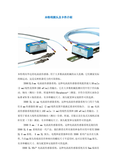
本特利探头及卡件介绍本特利内华达的电涡流传感器。
用于大多数涡流机械的永久监测,它们测量实际的轴运动,这是反映机器受力的可靠指标。
3300 XL 8 mm 电涡流传感器系统:这种电涡流传感器系统提供最大80 mils (2 mm)线性范围和200 mV/mil的输出。
它在大多数机械监测应用中用于径向振动、轴向(侧向)位移、转速和相位(Keyphasor® )测量,并符合美国石油协会标准670第4版的要求。
有多种螺纹尺寸、探头配置和安装附件可供选择。
3300 XL 11 mm 电涡流传感器系统:这种电涡流传感器系统专门用于当我们8 mm传感器的80 mil (2 mm)线性范围不能满足要求时的场合。
11 mm 电涡流传感器系统提供最大180 mils (4 mm)的线性范围和100 mV/mil的输出,主要用于要求大线性范围的轴向(测向)位移、转速、差胀以及往复式压缩机活塞杆位置(下落)测量。
有多种螺纹尺寸、探头配置和安装附件可供选择。
3300 5 mm / 8 mm 电涡流传感器系统:这种电涡流传感器系统是我们的3300 XL 8 mm 系统的前一代产品,我们推荐在所有新的和备件应用中使用3300 XL 8 mm系统。
8 mm XL 探头、电缆和前置器和旧的 3300 系列产品具有互换性。
当8 mm探头的端部直径和相应的螺纹尺寸不适用时,也可以使用5 mm探头。
有多种螺纹尺寸、探头配置和安装附件可供选择。
3300 XL NSv™ 电涡流传感器系统:这种电涡流传感器系统具有5mm端部直径和60 mils (1.5 mm)的更短线性范围,适用于被测靶面区域小、侧视或沉孔间隙减小以及其它限制使用我们标准的 5 mm / 8 mm 电涡流传感器的情况。
3300 16 mm 高温电涡流传感器系统:这种电涡流传感器系统用于最高350℃ (662°F)的高温环境,如温度超过我们标准电涡流探头和电缆能够承受的极限的某些燃气和蒸汽轮机应用。
Bently Nevada 3300XL 转动速度传感器辅助设备数据手册说明书
DescriptionAccessories contribute to a reliable transducer system. Installing proximity probes during outages usually requiresone or more mounting accessories to help simplify the task.3300XL Transducer AccessoriesDatasheetBently Nevada Machinery Condition Monitoring145668Rev.HThese accessories allow you to quickly and efficiently install proximity probes and route the associated cables out of the machine case. These parts also help shield the cables from electrical noise and adverse environmental conditions. Having the proper mounting hardware on-site during the probe installation saves time and money for those responsible for the project.Junction boxesJunction boxes are normally mounted on or near the exterior of a machine case and enclose electrical connections in weatherproof or explosion-proof environments. Sealtite™ flexible conduit Flexible conduit routes probe cables safely to the sensor housing and then back to the monitors. The conduit protects transducer wiring from damage that splashing liquids or accidental contact with other equipment can cause.Sealtite flexible conduit consists of a galvanized steel core with an extruded thermoplastic cover. Pipe fittings are made of steel with a zinc-plated, chromate finish and are compatible with fittings found on our watertight equipment enclosuresProbe mounting bracketsProbe mounting brackets attach internally mounted proximity probes to the machine case. S upplied mounting bolts attach the bracket to the bearing or other location inside the machine casing. The bracket holds the probe and allows for adjustment of the probe tip relative to the observed surface.For most installations, use the standard 137492 non-clamping aluminum probe bracket. When using the 137491 brackets for 3/8-inch diameter smooth case probes, tightening the bolts will compress the probe hole around the probe and lock the probe into its preset gapped position. If your application requires additional electrical isolation from the mounting location (as in some generator and electric motor bearing locations), use the 27474 phenolic probe bracket. These mounting brackets are compatible with our 3300 and 3300 XL proximity probe systems, including 5 mm, 8 mm and NSv™ probes.To ensure that the brackets screws remain fastened within the machine, secure the screws with safety wire. Each mounting bracket includes special screws with holes drilled for safety wire.Cable SealThe optional 10076 Cable Seal is mainly for use in cable routing applications. It restrains the coaxial cable from movement, prevents abrasion, and provides splash protection. One end of the cable seal has a 1/4-18 NPT thread that allows you to thread it into a 4190-36 Adapter.The cable seal has an aluminum body and an oil-resistant, slit grommet so that you can install it over armored or non-armored cable without removing the connectors. AdapterThe optional 4190 Adapter attaches a junction box to the machine case. It also allows mounting of the proximity probe in some instances.The adapter offers a variety of threads and configurations. A dapter threads and configurations that are not listed in this data sheet may be available. P lease contact your sales representative for more information. Explosion-proof fittingsExplosion-proof fittings provide seals for housings in Division 1 and in Zone 0 and 1 hazardous areas. The fittings include sealing compound, packing fiber, and the appropriate adapter. Fitting kits are available. Refer to Explosion-Proof Fittings on page 6 for details and part numbers.Low-pressure cable sealThe 43501 Low-Pressure Cable Seal provides egress for up to 4 75Ω and/or 95Ω 3300XL, 3300 and 7200 cables, or up to 2 25mm DE or 50mmDE transducer cables, through a single hole in a machine case or other barrier.The cable seal is constructed of 303 stainless steel and a molded silicon rubber grommet and prevents leakage of fluids along the outer jacket of the cable. The seal has threads on both ends and fits into a tapped hole on the machine case or barrier. External pipe threads enable the seal to mate to conduit or housings. You can use the low-pressure cable seal only with non-armored cables. Its design seals pressures up to 345 kPa (50 psi) when properly installed.High-Temperature Cable TiesThe 173873 high-temperature cable tie is an economical alternative to metal brackets in high-temperature applications. These cable ties are molded from VICTREX® PEEK™ polymer for multiple uses in extreme environments up to +180°C (+356°F).SpecificationsJunction BoxesCylindrical Junction Box P/N 03818016 ComponentsMain body and blankcoverDimensionsOverall Height76 mm (3.0 in)Body Diameter89 mm (3.5 in)Hub-to-Hub121 mm (4.75 in) Base to Hub Center16 mm (0.64 in) Fittings3/4-14 NPT5 placesMaterial AluminumOptional Extension for 03818016 P/N 03818022ComponentsMain body Dimensions (Extensiononly)Overall Height93mm (3.7 in)Body Diameter90mm (3.6 in)Hub-to-Hub (flats)91 mm (3.6 in)Total ExtendedHeight150 mm (5.90 in) Material Aluminum Rectangular Junction Box P/N 03818065 ComponentsMain body and cover Dimensions Overall Height27.9 mm (1.10 in) Width of Body38.1 mm (1.50 in) Length of Body95.3 mm (3.75 in) Fittings1/2-14 NPT2 places Material Aluminum Rectangular Junction Box P/N 03818066 ComponentsMain body and cover Dimensions Overall Height61.0 mm (2.40 in) Width of Body44.5 mm (1.75 in) Length of Body102 mm (4.00 in) Fittings3/4-14 NPT2 places Material Aluminum Sealtite Flexible Conduit Components Refer to Figure 4.Fitting Options1/2-14 NPT3/4-14 NPTLength As ordered BracketsClamp Mounting Bracket for 3/8-inch diameter smooth body probesDimensions Refer to Figure 5.Mounting Screw Thread Size Options 10-24 UNC-2A M5 x 0.8-6gMaterial AluminumNon-Clamping Mounting Bracket for threaded case probesDimensions Refer to Figure 6. Mounting Screw Thread Size10-24 UNC-2Aor M5 x 0.8-6g Material Aluminum Probe Lock NutThread Sizes 3/8-24 UNF-2B M10 x 1-6HFeatures Lock nut with holes to attachsafety wire.Cable Seal (P/N 10076) Components Refer to Figure 7Overall length (assembled)35mm (1.4 inches) in tightened conditionAdaptersFeatures Refer to Figure 8 4190-01Dimensions Internal Diameter9.53 mm (0.375 in) Internal thread type1/4-18 NPT External thread type1/2-14 NPT Overall Length38.1 mm (1.50 in) 4190-03Internal Diameter11.1 mm (0.437 in) Internal thread type1/4-18 NPT External thread type3/4-14 NPT Overall Length46.0 mm (1.81 in) 4190-04Internal Diameter7.14 mm (0.281 in) Internal thread type1/4-28 UNF-2B External thread type1/2-14 NPT Overall Length38.1 mm (1.50 in) 4190-06Internal Diameter10.3 mm (0.406 in) Internal thread type3/8-24 UNF-2B External thread type1/2-14 NPT Overall Length38.1 mm (1.50 in) 4190-16Internal Diameter10.3 mm (0.406 in) Internal thread type3/8-24 UNF-2B External thread type3/4-14 NPT Overall Length46.0 mm (1.81 in) 4190-20Internal Diameter16.7 mm (0.656 in) Internal thread type5/8-18 UNF-2B External thread type3/4-14 NPT Overall Length46.0 mm (1.81 in)4190-34Internal Diameter7.14 mm (0.281 in) Internal thread type1/4-28 UNF-2B External thread type3/4-14 NPT Overall Length56.1 mm (2.21 in) 4190-36Internal Diameter10.3 mm (0.406 in) Internal thread type1/4-18 NPT3/8-24 UNF-2B External thread type3/4-14 NPT Overall Length56.1 mm (2.21 in) Material304 Stainless Steel Explosion-Proof Fittings29368-01 Optional Fitting KitKit contains the following:03818056Hazardous area ¾” sealing fitting,conduit04576120 4 OZ adhesive sealant20892-02fiber seal03839246.750” aluminum plug72340 Fitting KitKit contains the following:03839246.750” aluminum plug 038500213/4 to 1/2 reducer thread fitting 49871-01cable grip assembly 03839153grommet sealing 250-312 ring 03839154grommet sealing 312-375 ring 20892-02fiber seal038180563/4 conduit fitting 03839155ring cable fitting 045761278 OZ adhesive sealant 04576120 4 OZ adhesive sealant 04760000string tag labelFeaturesRefer to Figure 9.Dimensions03818055Conduit size1/2-14 NPT Overall Length69.9 mm (2.75 in) Width49.3 mm (1.94 in) Min. turn radius63.5 mm (2.50 in) 03818056Conduit size3/4-14 NPT Overall Length69.9 mm (2.75 in) Width49.3 mm (1.94 in) Min. turn radius63.5 mm (2.50 in) 03818058Conduit size1-1/4 NPT Overall Length102 mm (4.00 in) Width54.1 mm (2.13 in) Min. turn radius57.2 mm (2.25 in) Material AluminumLow Pressure Cable SealDimensions Refer to Figure 10 Fitting Options1/2-14 NPT3/4-14 NPTHigh Temperature Cable TiesTemperature Up to +180°C (+356°F)Material VICTREX PEEK polymerOrdering InformationFor the detailed listing of country and product specific approvals, refer to the Approvals Quick Reference Guide (108M1756) available from .Sealtite Flexible Conduit3/4-14 NPT assembly Minimum length: 1 foot Maximum length: 99 feet Example: 0 1 = 1 foot9 9 = 99 feetAluminum Clamp Mounting Bracket for 3/8-inch Diameter Smooth Body Probes137491-AXXAluminum Non-ClampingMounting Bracket for Threaded Case Probes137492-AXXThe -0 1 and –0 2 option are supplied with two 10-24 UNC-2A mounting screws with safety wire holes. The -0 3 and -0 4 options are supplied with two M5 x 0.8-6g mounting screws with safety wireholes.Phenolic Mounting Bracket27474-AXXThe -0 1 and -0 2 options are supplied with two 10-24 UNC-2A mounting screws with safety wire holes. The -0 3 and -0 4 options are supplied with two M5 x 0.8-6g mounting screws with safety wire holes. The dimensions are identical to the aluminum mounting bracket 137492.Cable Seal10076-AXX0 150 Ω, without armor0275/95 Ω, without armor0 375/95 Ω, with armor0 450 Ω, with armorAdapter4190-AXXXX See Specifications section for dimension details.Additional sizes and configurationsavailable in both standard product andspecial modifications. Contact yourlocal sales representative for details. Low Pressure Cable Seal43501 – AXX – BXX - CXXJunction Boxes03818016Cylindrical Junction Box. 03818022Optional Extension for CylindricalJunction Box.03818065Rectangular Junction Box.Dimensions (W x L x D) 38.1mm x95.3mm x 29.7mm (1.10in x 1.50in x3.75in x 1.10in).03818066Rectangular Junction Box.Dimensions (W x L x D) 44.5mm x102mm x 61.0mm (1.75in x 4.00in x61.0in).Explosion-Proof Fittings038180551/2-14 NPT Fitting 038180563/4-14 NPT Fitting 03818057 1 to 11½ NPT Fitting 038180581¼ to 11½ NPT FittingProbe Lock Nuts043010073/8-24 UNF-2B. 04301008M10 x 1-6H. Accessories for Low Pressure Cable Seal04490104Punch tool kit for solid grommetoption.43574-04Replacement grommet. For up to 4cables.43575-04Replacement washerField Wiring021730062-conductor, twisted, shielded 18AWG (1.0 mm2).021730083-conductor, twisted, shielded 22AWG (0.5 mm2).021730093-conductor, twisted, shielded 18AWG (1.0 mm2).Use 2-conductor cable with velocitytransducers. U se 3-conductor cablewith Proximitor Sensors and interfacemodules. Specify number of feet whenordering.High Temperature Cable Ties 173873Bag of 50 Multiple-Use VICTREX PEEK Polymer Cable ties. For extreme environments up to+180°C (+356°F). One or more sizes/quantities available(?), including 7 inches long. Electrical Isolator19094-017200 Proximitor Sensor and Interface Module Isolator. P rovides electrical isolation for the 7200 Proximitor Sensor, velocity to displacement converters, and accelerometer interface modules.Graphs and FiguresAll dimensions shown in millimeters (inches) except as noted.1. Junction Box (03818016)2. Low Pressure Cable Seal (43501-02-04-02)3. High Temperature Cable Ties (173873)4. 3300 XL 8mm Probe (330101)5. Probe Mounting Brackets (137492-01)6. Connector Protectors (40113-02)7. Flexible Conduit (14848)8. Machine Case9. Machine ShaftFigure 1: Typical Internal Mounting Arrangement for an XY Proximity Probe Application1. 1. 121 (4.75) Typ.2. 2. 89 (3.50) Dia.3. 3. 90 (3.55) Dia.Figure 2: Cylindrical Junction Box and Optional ExtensionFigure 3: Junction BoxFigure 4: Sealtite™ Flexible Conduit1. 1. 5.11 (0.201) Dia.Figure 5: Clamping Aluminum Probe Bracket1. 5.11 (0.201) Dia.Figure 6: Non-Clamping Aluminum Probe Bracket1. 3/4 Hex2. 1/4 NPTFigure 7: Cable Seal1. Internal Diameter2. Internal Thread3. External Thread4. 4. 1-1/8 HexFigure 8: 4190 Adapter - 304 stainless steel (-34 Shown)Copyright 2020 Baker Hughes Company. All rights reserved.Bently Nevada and Orbit Logo are registered trademarks of Bently Nevada, a Baker Hughes Business, in the United States and other countries. The Baker Hughes l ogo is a trademark of Baker Hughes Company. All other product and company names are trademarks of their respective holders. Use of the trademarks does not imply any affiliation with or endorsement by the respective holders.Baker Hughes provides this information on an “as is” basis for general information purposes. Baker Hughes does not make any representation as to the accuracy or completeness of the information and makes no warranties of any kind, specific, implied or oral, to the fullest extent permissible by law, including those of merchantability and fitness for a particular purpose or use. Baker Hughes hereby disclaims any and all liability for any direct, indirect, consequential or special d amages, claims for lost profits, or third party claims arising from the use of the information, whether a claim is asserted in contract, tort, or otherwise. Baker Hughes reserves the right to make changes in specifications and features shown herein, or discontinue the product described at any time without notice or obligation. Contact your Baker Hughes representative for the most current information.The information contained in this document is the property of Baker Hughes and its affiliates; and is subject to change without prior notice. It is being supplied as a service to our customers and may not be altered or its content repackaged without t he express written consent of Baker Hughes. This product or associated products may be covered by one or more patents. See /legal.1631 Bently Parkway South, Minden, Nevada USA 89423Phone: 1.775.782.3611 or 1.800.227.5514 (US only)。
本特利传感器介绍

基于安装
传感器安装位置 • 测轴位移的传感器应尽可能靠近推力 轴承 • 测径向振动的传感器
– 安装在同一轴向平面内 – 两个传感器正交分布
考虑安装空间的限制
保证测量精度
加速度传感器 • 安 装 点 清 理 油 漆、 异 物 • 安装点保证一定的平面度 键相位传感器 • 每 个 转 速 或 旋 转 方 向 不 同 的 轴, 都 应 安装一个键相位传感器
or
= 7.87 mV/um
组成元件不匹配的影响
24 22 20
SHORT
18
OUTPUT (-Vdc) (
16 14 12 10 8 6 4 2 0 0 10 20 30 40
CORRECT
LONG
50
60
70
80
90
100 110 120 130 140
PROBE GAP (mils)
输入电压的影响
Velomitor 的 频 率 响 应
Velomitor 的 特 点
优点 • 安装简便 • 良好的中频响应 • 长时间使用可靠性好 • 使用温度范围宽
Velomitor 的 特 点
缺点 • 校验需要振动台 • 需要连续供电 • 低频响应差
加速度传感器 (Accelerometer)
加速度传感器的结构
<100mil
线性范围
RF SIGNAL
趋近传感器系统 - Eddie Current
导电材料
RF 信 号
电涡流
趋近传感器系统– Gap Signal 近传感器系统
RF SIGNAL
0
RF SIGNAL
0
RF SIGNAL
0
趋近传感器系统– Prox Output 近传感器系统
仪表本特利3500系统

延伸电缆和探头的长度总和必须等于前置器上标明的总电气长度
4、振动、位移变送器
3500监测系统的组成
5、电涡流 电感线圈产生的磁力线经过金属导体时,金属导体就会产生感应电流,且呈闭合回路,类似于水涡流形状,故称之 为电涡流也叫做电涡流效应.
3500监测系统的组成
3500监测系统的作用
4、键相传感器 电涡流传感器可以用来有效得提供基准相位信息。键相传感器的典型安装是将其探头呈放射状安装在转子周围,当转轴每次旋转时,就可以感知轴上设计特征信息(键槽等)。键相传感器可以创建一个基准信号用于测量绝对相位信息及确定机器的转速。 前置器系统被安装好之后,将观测到大轴上的“凹槽”或“突出”的地方会比正常的振动或距离测量产生明显的电压变化。这种明显的差别使得3500监测系统将每转一周产生的有用的信号与背景的噪音信号或振动信号区分开来。键相位信号在机组故障诊断中非常有用。
3500监测系统的作用
0
+
-
从驱动器向轴的驱动端看去。是垂直或Y探头始都在水平或X探头向左或逆时针90方位上。方向一般为左45度和右45度。振动探头的基准电压一般在-8~-12V之间,一般为-9.75V,距离单位为UM PP(PP为峰峰值)。
3500监测系统的组成
2、延长导线(1)延长导线的结构:导体芯、内屏蔽层、外屏蔽层、绝缘层。 1)内屏蔽层和导体芯提供了顶部线圈到探头电缆微型连接器末端的连接。 2)外屏蔽层是没有连接到线圈或连接器,所以它不是系统的电气性能的一部分。这个外屏蔽层提供了内屏蔽层的 机械保护。如果电缆的外层聚四氟乙烯涂层损坏,这可以防止不必要的线圈接地。内屏蔽接前置器COM端,如 果在正常生产中外屏蔽遭到破坏建议及时更换。不同型号、类型接头塑封的颜色不同,如蓝色、紫色、灰色。(2) 延长导线标签含义例如:330130-080-00-00 080 = 8.0米的总长度 00 =没有防护型外壳 00 =危险区域,不需认证 3300 XL电涡流传感器系统, 可用扩展电缆长度为3.0,3.5, 4.0,4.5,7.5,8.0和8.5米。
本特利3300监测系统说明书

5. 间隙报警 同时按住 GAP 和 ALART 开关以显示间隙报警点。当间隙水平等于 或大设定点 6 秒钟,ALERT LED 将亮起来而相应报警继电器开关动作。
我厂有三套 3300 系统,大机 3300 系统配备有电源,系统监视器,六个双通道振动 监视器及其相应的传感器系统及一套多通道诊断仪,另外推力轴承磨损、偏心、机壳膨 胀、胀差由本特利提供探头和前置器,而无本特利监视仪表。电泵有两套 3300 系统各 配备有电源,系统监视器,六个双通道振动监视器和六个六通道温度监视器及其相应的 传感器系统。小汽轮机的振动、推力轴承磨损和偏心的探头和前置器由本特利提供,信 号直接进入小机 MARK-V 而无本特利监视仪表。
三.系统调试 1. 探头--前置器静态特性校验 将轴振探头安装在校验台上,用同轴电缆连接好探头和前置器,并将探头靠紧被测
所有电缆及其联接,其工作是否正 常?
是 更换变压器
否
更换电源输入模块
转向第 1 步
所有电压是否都在表中所列的公 差范围之内?
是 参照系统监测器手 册更换系统监测器
否 转向第 6 步
转向第 1 步
6 把电源和系统监测器留在框架之内,同时 把一个监测器从系统中取出,把监测器前 面板上的螺钉松开,然后把监测器从框架 前面拉出约两英寸,使其与框架不在结合。 这时观察在系统监测器上指示电源是否正 常的发光二极管。使监测器继续保持与框 架分离状态,直到指示电源是否正常的发 光二极管亮或者等到所有监测器都与框架 分离。
本特利330500&525&530

2.3.4 铠装电缆布线 ..............................................................................................................................24
2.3.5 连接电缆密封 ..............................................................................................................................24
/bently
ii
补充信息
注意:
本手册未包含操作和维护该产品所必需的全部信息。如需要请参考下列相关资料手 册。
3500/42M 电涡流/地震式监测器操作与维护手册 (143489-01) 3300/55 双通道速度监测器操作手册 (130747-01) 3300/55 双通道速度监测器维护手册 (130748-01)
2.3.2 330525 Velomitor®压电式速度传感器的电缆布线..................................................22
2.3.3 330530 Velomitor®压电式速度传感器的电缆布线..................................................22
3.
3.1
iv
维护 ..........................................................................................................27
本特利内华达3300 XL 8mm涡流传感器手册

(位置与方向-轴向位移探头)。美国石油协会出版发行,1220 L Street NW,
Washington DC,20005,USA
参考文件(133055-01)
本特利内华达术语表
iii
3300 XL 8 毫米和 3300 5 毫米涡流传感器系统安装手册
产品处置声明
使用本产品或产品达到使用寿命期限后的非欧盟成员国家客户和第三方是恰当处置产 品废弃物的唯一责任人。任何个人、公司、组织或者机构在产品使用过程中不得违反 美国州法律、美国联邦法律、当地国家法律或国际法律对废弃物的规定。本特利内华 达公司不承担产品使用过程中或者达到寿命期限后废弃物处理的责任。
安装传感器
•
涡流探头和相关附件的最佳实践经验:电涡流传感器的安装与应用
•
本特利内华达旋转机械信息系统接地导则
•
危险区域内电气设备的安装
•
电涡流探头用于超速保护时的注意事项
•
“小故障”:消除电气跳动的轴抛光等校正的定义与方法
传感器安装附件
•
31000/32000 涡流探头防护箱手册(部件号 124200-01)
vi
目录
1. 系统综述 .......................................................................................................... 1
1.1 传感器系统 .......................................................................................................................................... 1 1.2 前置器 .................................................................................................................................................... 1 1.3 涡流探头和延长电缆 ...................................................................................................................... 2 1.4 接头 ......................................................................................................................................................... 2 1.5 扩展的温度范围应用 ...................................................................................................................... 2 1.6 到货检查与系统拆装 ...................................................................................................................... 3 1.7 客户服务 ............................................................................................................................................... 3
本特利3300系统505系统

压 = 零点电压 - 窜量*选取的线性范围平均灵敏度/2)
压缩机组常用的监控系统
3、监测系统
1)BENTLY 3300监视仪
❖ 特点:液晶数字式表头、通过DIP开关和内部短接片进行组态设定、4~14个
可选位置的框架结构。
❖ 主要硬件
➢ 电源模件:3300/12(115、220VAC)、3300/14(DC电源) ➢ 监测器模件:3300/03,对框架中的模件进行报警设定点调整、报警确认复位;连接
键相位传感器,为其提供电源;实现框架内各安装模件的内部通讯等;
➢ 双通道振动监测器模件(3300/16):连续测量两个轴振动及间隙电压信号。
➢ 延伸电缆 + 探头长度应与前置器相匹配 ➢ 探头直流阻抗位于6.95~10.77Ω之间; ➢ 3300 XL前置器到监测器 ≤ 305 米; ➢ 电涡流传感器系统只允许单端(现场或控制室)接地; ➢ 电涡流传感器系统的线性范围为 2mm(80mils); ➢ 电涡流传感器系统的灵敏度:标准5m、9m系统分别为7.87V/mm
❖ H2抵消部分H1,导致线圈阻抗Z、电感L、品质因数Q 发生变化;
❖ 选取某一参数(如:L、Z),经一定的转换电路可将 参数的变化转换成电压输出;
❖ 研究参数与距离间的对应函数关系,使其构成单值函 数,如:Z = f(ρ、μ、x、ω)
压缩机组常用的监控系统
5)BENTLY 3300 XL电涡流传感器型号简介
(200mV/mil)±5%、7.87V/mm(200mV/mil)± 6.5%。
压缩机组常用的监控系统
6)传感器探头的安装
➢ 外观检查 ➢ 测量直流阻抗 ➢ 静态调校: TK3校验仪、数字电压表 ➢ 以测得探头线性范围的中点电压作为安装的参考电压(-8~-
美国本特利3300耐高温电涡流传感器系统
C: 硬连线长度 选项:
1 0 1.0 米 (3.3 英尺) 2 0 2.0 米 (6.6 英尺) 5 0 5.0 米 (16.4 英尺)
D: 总长度 选项:
注:延伸电缆包含在电涡流 探头中 9 0 9.0 米 (29.5 英尺)
பைடு நூலகம்
E: 延伸电缆铠装 选项:
0 0 无不锈钢铠装 0 1 不锈钢铠装
F: 批准机构 选项:
50Ω
探头直流阻抗
探头长度(m) 从中心导体到外部导体的阻抗 (RPROBE)(ohms)
1.0
5.06
2.0
5.82
5.0
8.11
延伸电缆直流阻抗:
延伸电 缆长度 (m)
从中心导体到中 心导体的阻抗 (RCORE)(ohms)
4.0
0.88
7.0
1.62
8.0
1.84
从同轴导体到同轴 导体的阻抗
(RJACKET)(ohms)
探头壳体材料:AISI 316L 不锈钢(SST)
探头电缆规格:
1、2 或 5 米长的 AISI 304L 不锈钢硬线电缆
延伸电缆材料: 75Ω三维轴向氟乙烯丙烯 (FEP)绝缘电缆
前置器材料:
环氧粉末涂层铝
系统长度: 包括延伸电缆为 9 米
延伸电缆铠装 (可选):
弹性 AISI302 SST 不锈钢,具有 FEP 外皮
推荐最小轴直径:152mm(6.0inch)
注:对直径小于 76mm(3.0inch)的轴进行测 量通常要求更近的径向振动 或轴向位移传感器间距,这 样有可能使它们的电磁场互 相干扰(串扰),导致读数 错误。为防止串扰,对于复 合轴向位移测量,传感器端 部相距至少 64mm(2.5inch),对于径向 振动测量,传感器端部相距 至少 54mm(2.1inch)。对直 径小于 152mm(6.0inch)的轴 进行径向振动或轴向位移测 量时,通常会由于轴表面圆 度的变化而导致灵敏度发生 改变。更多信息请参阅性能 技术说明 159132。
本特利TSI3500-培训资料及总结【可编辑范本】
本特利TSI3500系列培训本次培训主要内容有涡流传感器和速度传感器的原理、特性及使用条件,T SI3500系统简介、框架与主计算机的通讯、框架组态及探头安装时的注意事项等。
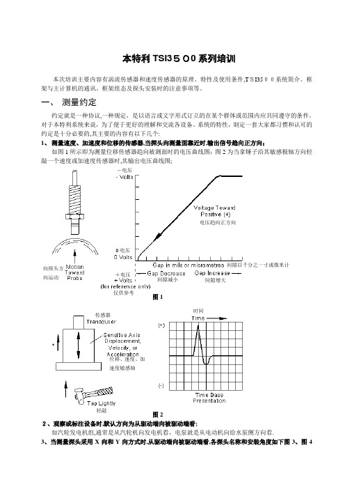
一、 测量约定约定就是一种协议,一种规定,是以语言或文字形式订立的在某个群体或范围内应共同遵守的条件。
对于本特利系统来说,为了便于更好的理解和交流各设备、系统的特性,制定一套大家都习惯和认可的约定是十分必要的,其主要的内容有以下几个:1、 测量速度、加速度和位移的传感器,当探头向测量面靠近时,输出信号趋向正方向;如图1所示即为测量位移传感器趋向被测面时的电压曲线图;图2为当拿锤子沿其敏感极轴方向轻敲一个速度或加速度传感器时,其输出电压曲线图;图1图22、观察或标注设备时,默认方向为从驱动端向被驱动端看;如汽轮发电机组,通常是从汽轮机向发电机看,电泵就是从电动机向给水泵侧方向看.3、当测量探头采用X 向和Y 向方式时,从驱动端向被驱动端看,各探头名称和安装角度如下图3、图4+电压向探头方向运动 电压趋向正方向-电压0电压间隙以千分之一寸或微米计 间隙减小 间隙增大 仅供参考 时间传感器 轻敲位移、速度、加速度敏感轴所示;图3向(左45°)向(左90°)向(0°)向(0°)向(右90°) 图44、通常Y 向探头接至1通道,X 向探头接至2通道,各信号线的颜色如下:如按照此规则接线,不仅使整个系统接线与本特利的各种资料能对照起来,对系统以后的调试、维护等都将带来很大的方便.结合以上各规则,我们就可以清楚的理解以下图5、图6所示,当转动轴沿所示特定轨迹运动时,其轴心轨迹及X 轴、Y轴输出电压随时间变化的曲线图了.Y 向振动信号线 蓝色X向振动信号线 绿色 键相信号线 黄色公共端 黑色电源线 红色 驱动端 任意旋转方向从驱动端看左上 右上 观察方向驱动侧 负载负载图5图6垂直,通道1水平,通道2垂直探头 水平探头从驱动端看水平垂直水平探头垂直探头 垂直,通道1水平,通道2水平垂直二、传感器特性本特利传感器一般分为位移传感器、速度和加速度传感器和机壳膨胀传感器。
本特利3500中文说明书

TSI系统调试基本知识本内容将围绕大多数电厂中广泛使用的美国本特利(BENTLY)公司生产的振动检测系统3500为模版,全面讲述系统安装、组态、调试过程及调试中常见问题的处理。
第一节 TSI系统硬件基本知识3500系统能提供连续、在线监测功能,适用于机械保护应用,并为早期识别机械故障提供重要的信息。
该系统高度模块化的设计主要包括:见下图:系统的工作流程是:从现场取得的传感器输入信号提供给3500监测器框架内的监测器和键相位通道,数据被采集后,与报警点比较并从监测器框架送到一个地方或多个地方处理。
3500框架中模件的共同特征是带电插拔和内部、外部接线端子。
任何主模件(安装在3500框架前端)能够在系统供电状态中拆除和更换而不影响不相关模块的工作,如果框架有两个电源,插拔其中一块电源不会影响3500框架的工作。
外部端子使用多芯电缆(每个模块一根线)把输入\输出模块与终端连接起来,这些终端设备使得在紧密空间内把多条线与框架连接起来变的非常容易,内部端子则用于把传感器与输入\输出模块直接连接起来。
外部端子块一般不能与内部端子输入/输出模块一起使用。
1、3500/05系统框架3500框架用于安装所有的监测器模块和框架电源。
它为3500各个框架之间的互相通讯提供背板通讯,并为每个模块提供所要求的电源。
3500框架有两种尺寸:1 全尺寸框架——19英寸EIA框架,有14个可用模块插槽2 迷你型框架——12英寸框架,有7个可用模块插槽电源和框架接口模块必须安装于最左边的两个插槽中。
其余14个框架位置(对与迷你型框架来说是其余7个位置)可以安装任何模块。
2、3500/15电源模块3500 电源是半高度模块,必须安装在框架左边特殊设计的槽口内。
3500 框架可装有一个或两个电源(交流或直流的任意组合)。
其中任何一个电源都可给整个框架供电。
如果安装两个电源,第二个电源可做为第一个电源的备份。
当安装两个电源时,上边的电源作为主电源,下边的电源作为备用电源,只要装有一个电源,拆除或安装第二个电源模块将不影响框架的运行。
内华达本特利传感器介绍V

内华达本特利传感器介绍V内华达本特利传感器(Nevada Benteli Sensor)是一家致力于传感器研发制造的技术公司,总部位于美国内华达州。
该公司成立于1990年,专注于开发和生产各种高性能传感器以满足不同领域的需求。
本特利传感器以其优良的质量、可靠性和创新性而闻名,被广泛应用于工业自动化、汽车、医疗设备、航空航天等领域。
1.光电传感器:本特利传感器的光电传感器具有高精度、高灵敏度和高稳定性的特点。
它们可以用于检测、测量和控制光信号,广泛应用于自动化生产线、机器人技术、安全监控系统等领域。
2.压力传感器:本特利传感器的压力传感器采用先进的压力测量技术,能够准确地感知压力变化并将其转换为电信号。
这些传感器广泛应用于汽车发动机控制、制造业、医疗设备等领域。
3.温度传感器:本特利传感器的温度传感器具有高精度和高稳定性,能够准确地测量温度变化并将其转换为电信号。
它们广泛应用于空调、冰箱、汽车、工业加热设备等领域。
4.流量传感器:本特利传感器的流量传感器适用于各种液体和气体的流量测量。
它们具有高精度、高可靠性和高灵敏度的特点,可以用于工业过程控制、液体计量、测量仪器等领域。
除了以上几种传感器,内华达本特利传感器还生产并提供其他类型的传感器,如声音传感器、振动传感器、位置传感器等。
这些传感器在各种应用中发挥着重要的作用,帮助提高生产效率、降低能耗、改善产品质量等。
为了保证产品的质量和可靠性,内华达本特利传感器拥有一支专业的研发团队和一套完善的质量管理体系。
公司不断进行技术创新和产品改进,以满足客户的需求,并在全球范围内建立了广泛的销售和服务网络。
总而言之,内华达本特利传感器是一家在传感器领域具有丰富经验和专业知识的公司,提供各种高性能的传感器产品。
它们的产品被广泛应用于汽车、工业自动化、医疗设备等众多领域,为客户提供了科技创新和高效率的解决方案。
美国BENTLY本特利传感器

美国BENTLY本特利传感器广州南创陈工美国BENTL Y(本特利),本特利(美国BENTL Y)在评估和确保工业设备的机械和热力学性能方面是全球领先的产品和服务供应商。
公司在全球43个国家的主要工业中心设有100个办事处。
BENTLY传感器的产品远销38个国家,在多个国家设立了分支机构或办事处,生产基地遍布美洲、东欧、中国等地;并在中国设立了广州南创传感器事业部,可为用户的实验和生产提供最佳的服务与解决方案。
其全球用户超过二万五千,分布于发电、石化以及其它众多行业是世界领先的产品和服务供应商,提供工业用机器及其它资产的机械学和热力学状态信息。
拥有全球最大的机械保护和连续状态监测系统安装容量,所提供的解决方案是有效的工厂资产管理策略的重要组成部分。
四十年来,一直致力于帮助用户保护和管理他们的机械。
本特利(美国BENTL Y)不但是仪表制造公司,还是世界闻名的机械专家。
在二十余年的研发工作中,积累了与转子动力学相关的丰富知识,掌握了排除故障、解决问题的专业技能,提供了上万次现场机械故障诊断服务。
如今,已经超越了旋转和往复机械——解决方案可以应用于任何工厂设备资产。
在各项衡量用户满意度的指标中,常盛不衰是最有说服力的。
当旧系统需要改造或者在状态监测项目中需要增加新资产时,是什么使用户仍然选择本特利内华达(美国BENTLY)是所取得的成效。
本特利内华达(美国BENTLY)的解决方案使用户的设备资产运行更安全、更高效、更可靠,为用户带来他们所期望的经济收益。
传感器包括振动、位移、转速、压力、能量、温度等种类。
产品特性描述:BENTL Y 9200速度传感器Seismoprobe速度传感器系统测量轴承箱、机壳或结构的绝对(相对于自由空间)振动,该两线系统由传感器、电缆和可选的速度-位移转换器组成。
对于大多数应用,BENTL Y 9200速度传感器的Velomitor系列速度传感器包含了固体技术,在机壳速度测量中性能高好,结构更加坚固。
机组仪表-本特利探头(传感器的静态校验)

(3)将-24VDC送到前置放大器的电源端和公共端,调节TK3-2E校验仪上的螺 旋千分尺,使示值对准0 mm处,然后将千分尺的示值增加到0.25 mm,记录 数字电压表的电压值(此值为前置器输出电压)。以每次0.25 mm的数值增加间 隙,直到示值为2.5mm为止,并记录每一次的输出电压值。(校验点不少于10 点)。
前置器检测电路检测探头线圈的感抗变化。再经放大电路 将感抗变化量变换放大成相应电压变化信号输出。经监测 仪进行信号转换并显示,转换成4~20mA,1~5V的标准信号送 入DCS或PLC中,在测量中,前置器放大输出的直流电压信 号用做机械位移的测量,交流电压信号用做振动的测量。
机械转速主要是测转子的齿轮或孔眼,经过传感器产生脉 冲或方波,并通过频率信号输出。在现场实际应用的传感 器原理不同。一般有电涡流传感器、磁电式传感器、光电 式传感器等
二、工作原理 机器的振动、位移总是伴随着机器的运转,即使是机器在
最佳的运动状态,由于很微小的缺陷,也将产生某些振动 。在工作中我们常用的振动位移监测仪是由电涡流传感器 、前置器、延伸电缆、监测仪转换器组成,其构成原理如 图所示。探头线圈监测仪
探头线圈接受前置器振荡电路来的高频电流,在其周围产 生高频磁场,该磁场穿过靠近它的转轴金属表面,在其中 产生一个电涡流,该电涡流产生的磁场方向和线圈磁场方 向相反,改变了原线圈的感抗,该感抗的变化随探头顶部 金属表面的间隙变化而变化。
(2)延伸电缆完整、无短路、无开路、接头无氧化锈蚀 ,保护层无破损。
(3)前置器完整无损,安装盒无脱漆、变形和密封不良 现象,前置器与安装盒之间需有良好的绝缘层。
(4)信号电缆屏蔽层接地良好,用500V兆欧表检查信号 线间及对地绝缘电阻应大于5 MΩ。并要求单点接地。
本特利电涡流传感器说明书
本特利电涡流传感器说明书一、产品概述本特利电涡流传感器是一种非接触式传感器,能够检测金属物体的位置、形状和尺寸等参数。
该传感器采用电涡流原理,通过感应金属物体表面的涡流信号来实现非接触式测量。
本特利电涡流传感器具有高精度、高灵敏度、高可靠性等优点,在工业自动化、机械制造、航空航天等领域得到广泛应用。
二、产品结构本特利电涡流传感器主要由以下部分组成:1. 传感头:负责检测金属物体表面的涡流信号;2. 信号处理单元:负责对传感头采集到的信号进行处理,并将结果输出;3. 外壳:保护传感头和信号处理单元,同时提供安装接口。
三、技术参数1. 测量范围:0-5mm;2. 测量精度:±0.01mm;3. 工作频率:10kHz;4. 输出方式:模拟输出(0-10V)和数字输出(RS485)可选;5. 工作温度范围:-20℃~80℃;6. 防护等级:IP67。
四、使用方法1. 安装传感器:将传感器安装在需要测量的金属物体上,注意保持传感头与物体表面间的距离不变;2. 连接电源:将传感器与电源连接,注意检查电源电压是否符合要求;3. 输出信号:根据需要选择模拟输出或数字输出方式,并将信号连接至控制系统。
五、注意事项1. 本特利电涡流传感器只能用于测量金属物体;2. 在安装和使用过程中,应注意保持传感头与物体表面间的距离不变,否则会影响测量精度;3. 在使用过程中,应避免强磁场和强电场的干扰。
六、维护保养1. 定期清洁传感头和外壳,并检查连接线路是否正常;2. 如发现异常情况(如输出信号不稳定等),应及时进行检修或更换。
七、常见问题解答1. 为什么只能用于测量金属物体?答:因为本特利电涡流传感器是基于金属材料导电性原理工作的,只有金属物体才能产生涡流信号。
2. 如何判断测量精度是否符合要求?答:可采用标准金属块进行校准,或与其他精度较高的测量设备进行比对。
3. 为什么会出现输出信号不稳定的情况?答:可能是由于传感头与物体表面间的距离变化、电源电压波动等原因造成的,应及时进行检修或更换。
本特利传感器330500资料

接头:
安装力矩: 极性:
订货信息
330500330500-AXXAXX-BXX 选项描述
EUROPEAN CENELEC:
A: 安装螺纹接头 选项
0 0 0 0 0 0
1 2 3 4 5 6
1/2 - 20 UNF M8 x 1 1/4 - 28 UNF 1/4 - 20 UNC 1/4 - 18 NPT 5/8 - 18 UNF
BENTLY NEVADA
MADE IN U.S.A.
R
VELOMITOR PN 330500
100 mV/in/s (4 mV/mm/s)
R
技术规格
如无特别说明,所有参数均在+25±5°C (+77±9°F)下确定。.
注: 在规范限以外操作将导致读数错误或失去监测作用。
电气特性
灵敏度: 频率响应:
注: Velomitor®传感器出厂装运时已安 装接头。 独立接头作为备件使用。
ቤተ መጻሕፍቲ ባይዱ
4612222-01 84661
10007600076-01 8940989409-01
89477
089410 -01 89411-01 894122-01 389413 -01 04300015
125065
02173006
3.94mV/mm/s (100 mV/in/s) ±5% 在 100 Hz 时 4.5 到 5 kHz (270 到 300 kcpm) ±3.0 dB, 6.0 到 2.5 kHz (360 到 150 kcpm) ±0.9 dB
BN 部件号 141632-01 版本 A, 2002 年 1 月
161191
电缆部件号- 电缆长度选项,单位为英尺: 订货时以 1.0 英尺(0.3 米)递 增。 XXXXX - AXX 例如: 0 9 = 9 英尺(2.74 米) 1 2 = 12 英尺(3.66 米) 1012122-01
本特利传感器简介

二、传感器介绍
本特利常用四种类型传感器:分别是涡流式位 移传感器、传统速度传感器、速度计速度传感器、 加速度传感器。
根据现场使用情况,下面就主要介绍涡流式位 移传感器: (一)涡流式位移传感器(趋近式) 1、组成
a、同轴电缆
SIG COM
b、探头部件号
注:3300101--代表英制 3300103/6—代表公制 3300105—代表反向安装 05—代表无螺纹长度(mm) 30—代表盒子长度(mm) 10—代表探头总长度 02—代表有连接头 00—代表不需要在危险区域使用
整流、滤波
3、电涡流位移传感器的应用
主要用于振动、轴位移、差胀、键相、偏心的测量。
速度计速度传感器
•速 度 计 速 度 传 感 器结 构
速度计速度传感器
•工 作 原 理
–传 感 器 承 受 振 动 时, 压 电 盘 受 力 产 生 的 电 荷 与 振 动 的 加 速 度 成 正 比。 –压 电 盘 产 生 的 信 号 在 传 感 器 内 部 经 过 积 分以振动速度的形式输出
2)、具体安装 固 定 支 架
调整探头
4、差胀
胀差是转子和汽缸之间的相对热膨胀,当热膨胀的差值超过允许间隙时,便可能产 生磨擦。在开机和停机过程中,由于转子与汽缸质量、热膨胀系数、热耗散系数的不同, 转子的受热膨胀和汽缸的膨胀就不相同。
具体安装 固 定 支 架
5、轴振
如图所示.机组轴振的测量范围:0~400μm;报警值:125μm;停机值:250μm
TSI重要参数及保护定值
轴振动:量程0-500微米 报警: 127微米, 延时: 3s, 危险: 254微米 延时: 3s. 非闭锁安装电压:-10V
轴位移:量程-2--+2mm报警:-1 or 1毫米, 延时: 1s, 危险: -1.2 or 1.2毫米 延时: 1s. 闭锁安装 方向:远离为正 安装电压:-10V
BENTLEY传感器产品资料

BENTLEY传感器产品资料BENTLEY传感器(英文名称:transducer/sensor)是一种检测装置,能感受到被测量的信息,并能将感受到的信息,按一定规律变换成为电信号或其他所需形式的信息输出,以满足信息的传输、处理、存储、显示、记录和控制等要求。
传感器的特点包括:微型化、数字化、智能化、多功能化、系统化、网络化。
它是实现自动检测和自动控制的首要环节。
本特利传感器或开关,由一个几乎完全闭合的包含磁铁和磁极部分的磁路组成,一个软磁铁叶片转子穿过磁铁和磁极间的气隙,在叶片转子上的窗口允许磁场不受影响的穿过并到达本特利速度传感器,而没有窗口的部分则中断磁场。
美国本特利传感器本特利传感器美国本特利系列电涡流传感器这种传感器可以直接观察到各种振动、位移、转速和时间(如相位)测量的轴或靶面位移。
由于有多种端部直径和螺纹尺寸可供选择和组合,所以其测量范围小到200微英寸(用于REBAM 测量),大到1英寸(通常用于大型蒸汽轮机的差胀测量),包括适用于大多数机器测量的80米耳范围。
速度传感器和加速度传感器与电涡流传感器直接观察机器的轴不同,壳体振动传感器安装于壳体上(通常是轴承箱体),测量壳体表面的振动。
这些产品包括加速度计和速度传感器。
因此,叶片转子窗口的作用是开关磁场,使本特利效应象开关一样地打开或关闭,这就是一些汽车厂商将本特利速度传感器和其它类似电子设备称为本特利开关的原因,该组件实际上是一个开关设备,而它的关键功能部件是本特利速度传感器。
本特利速度传感器的特点包括:微型化、数字化、智能化、多功能化、系统化、网络化,它不仅促进了传统产业的改造和更新换代,而且还可能建立新型工业,从而成为21世纪新的经济增长点。
微型化是建立在微电子机械系统(MEMS)技术基础上的,已成功应用在硅器件上做成硅压力传感器。
美国BENTLEY本特利传感器原装现货啦;本特利传感器优点:1)输出信号电压幅值不受转速的影响2)频率响应高,其响应频率高达3)抗电磁波干扰能力强主要功能常将本特利传感器的功能与人类5大感觉器官相比拟:光敏传感器——视觉声敏传感器——听觉气敏传感器——嗅觉化学传感器——味觉压敏、温敏、流体传感器——触觉本特利传感器的特点包括:微型化、数字化、智能化、多功能化、系统化、网络化,它不仅促进了传统产业的改造和更新换代,而且还可能建立新型工业,从而成为21世纪新的经济增长点。
330500 Velomitor Piezo-velocity Sensor说明书
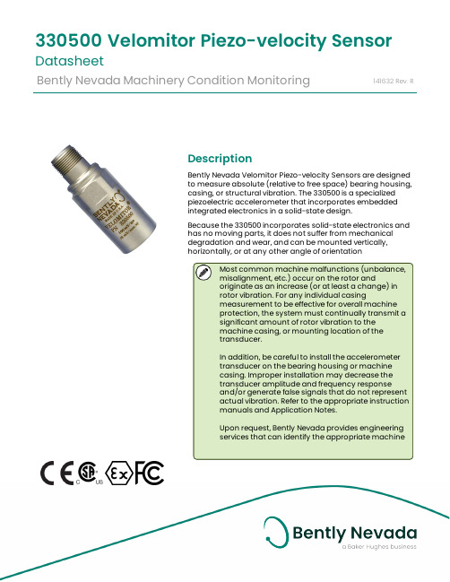
DescriptionBently Nevada Velomitor Piezo-velocity Sensors are designedto measure absolute (relative to free space) bearing housing,casing, or structural vibration. The 330500 is a specializedpiezoelectric accelerometer that incorporates embeddedintegrated electronics in a solid-state design.Because the 330500 incorporates solid-state electronics andhas no moving parts, it does not suffer from mechanicaldegradation and wear, and can be mounted vertically,horizontally, or at any other angle of orientationMost common machine malfunctions (unbalance,misalignment, etc.) occur on the rotor andoriginate as an increase (or at least a change) inrotor vibration. For any individual casingmeasurement to be effective for overall machineprotection, the system must continually transmit asignificant amount of rotor vibration to themachine casing, or mounting location of thetransducer.In addition, be careful to install the accelerometertransducer on the bearing housing or machinecasing. Improper installation may decrease thetransducer amplitude and frequency responseand/or generate false signals that do not representactual vibration. Refer to the appropriate instructionmanuals and Application Notes.Upon request, Bently Nevada provides engineeringservices that can identify the appropriate machine 330500Velomitor Piezo-velocity Sensor DatasheetBently Nevada Machinery Condition Monitoring141632Rev.Rhousing measurements andinstallation assistance if needed.If you integrate the 330500 Velomitoroutput to measure displacement,electrical noise from interference andthe transducer circuit can beamplified. The noise can degradeperformance of 330500 transducersand produce inaccuratedisplacement data.SpecificationsParameters are specified from +20 °C to +30 °C (+68 °F to +86 °F) and at 100 Hz unless otherwise indicated.Operating the transducer outside thespecified limits may result in falsereadings or loss of machinemonitoring.ElectricalSensitivity 3.94mV/mm/s (100 mV/in/s)±5%.Frequency Response 4.5 Hz to 5 kHz (270 cpm to 300 kcpm) ±3.0 dB.6.0 Hz to 2.5 kHz (360 cpm to 150 kcpm) ±0.9 dB.Temperature Sensitivity -14% to +7.5% typical over the operating temperature range.Velocity Range 1270 mm/s (50 in/s) peak. TransverseSensitivity Less than 5% of sensitivity.Amplitude Linearity ±2% to 152 mm/s (6 in/s) peak.MountedResonantFrequencyGreater than 12 kHz.Output Bias Voltage -12 ±3.0 V DC, over temperature referenced to Pin A.DynamicOutputImpedanceLess than 2400 ΩBroadband Noise Floor (4.5 Hz to 5 kHz) 0.004 mm/s (160 μin/s) rms, nominalGrounding Case isolatedMaximumCable Length305 metres (1,000 feet) ofcable, part number 02173006,with no degradation ofsignal. Environmental LimitsOperatingTemperatureRange-55°C to 121°C(-67°F to 250°F)ShockSurvivability 5,000 g peak, maximumRelativeHumidityTo 100% non-submerged;case is hermetically-sealed.Base StrainSensitivity 0.005 in/s/mstrain. Magnetic FieldSusceptibility<51 min/s/gauss (50 gauss,50-60Hz).PhysicalWeight 142 grams (5.0 oz), typical. Diameter 25.3 mm (0.995 in). Height 63.2 mm (2.49 in).Case Material 316L stainless steel.Connector 2-pin Mil-C-5015 hermetically-sealed, 316L stainless steel shell.Mounting Torque 32-46 kg cm (24-40 in-lb) max.Polarity When the sensor case motion is toward the connector, Pin A becomes positive with respect to pin B.Recommendedcable length(assumingmax vibrationof 50g,frequency 10kHz, and cable capacitance200 pf/m.) Forlonger lengths,contact BentlyNevada Tech Support.)208 ft (63m)Compliance and CertificationsFCCThis device complies with part 15 of theFCC Rules. Operation is subject to thefollowing two conditions:l This device may not cause harmfulinterference.l This device must accept anyinterference received, includinginterference that may causeundesired operation.EMCEMC Directive 2014/30/EURoHSRoHS Directive 2011/65/EU MaritimeDNV rules for classification – ShipsDNV rules for classification – Highspeed and light craftDNV offshore standardsHazardous Area ApprovalsFor the detailed listing of country andproduct specific approvals, refer tothe Approvals Quick Reference Guide(108M1756) available from . CSA/NRTL/C190501 (Agency Approval Options 01 through 04)Intrinsically Safe Ex ia IIC T4:Class I, Div 1, Groups A, B, C, D. Class II, Group E, F and G Class IIIAEx ia IIC T4:Class I, Div 1, Groups A, B, C, D; Class II, Groups E, F, GClass IIIInstall per drawing 167536T4 @ -40°C ≤ Ta ≤ +100°C (-40°F ≤ Ta ≤ +212°F)Intrinsically Safe and Non-Incendive Ex nL IIC T4Class I, Division 2, Groups A, B, C and DAEx nA T4Class I, Division 2, Groups A, B, C and D Install per drawing 167536T4 @ -40°C ≤ Ta ≤ +100°C(-40°F ≤ Ta ≤ +212°F)330400, 330425 Ex ia IIC T4AEx ia IIC T4Class I, Div 1 Groups A, B, C and D Class II, Groups E, F, and G Class IIIT4 @ -40°C ≤ Ta ≤ 100°CInstall per dwg 167538330500Ex ia IIC T4AEx ia IIC T4Class I, Division 1, Groups A, B, C and DClass II, Groups E, F, GClass IIIInstall per dwg 167537T4 @ -40°C ≤ Ta ≤ 100°CEx nL IIC T4AEx nA IIC T4Class I, Div 2, Groups A, B, C, DInstall per dwg 167537T4 @ -40°C ≤ Ta ≤ 100°C 330525Ex ia IIC T4AEx ia IIC T4Class I, Division 1, Groups A, B, C and DClass II, Groups E, F, GClass IIIT4 @ -40°C ≤ Ta ≤ 100°CEx nL IIC T4AEx nA IIC T4Class I, Div 2, Groups A, B, C, DInstall per dwg 167539T4 @ -40°C ≤ Ta ≤ 100°CATEX/IECEx190501, 330400, 330425, 330500, 330525190501Entity ParametersII 1 GEx ia IIC T4 GaII 3 DEx na IIC T4 GcEx tc IIIC T130°C DcT4@ Ta = -55°C to 121°CZone 0/1 Zone 2 Ui= 30V Ui= 30V Ii= 200mA Ii= 200mA Pi= 0.75W Pi= 1.14W Ci-27.2nF Li= 0330400, 330425, 330500, 330525EntityParametersII 1 GEx ia IIC T4 GaII 3 DEx na IIC T4 GcEx tc IIIC T130°C DcT4@ Ta = -55°C to 121°CZone 0/1 Zone 2 Ui= 28V Ui= 28V Ii= 150mA Ii= 150mA Pi= 0.84W Pi= 1.26W Ci-10.8nF Li= 0Hazardous Area Conditions of Safe UseATEX/IECExZone 0/1:Equipment must be connected to equipment, which meets the abovelisted entity parameters.The cables type A or B (in compliance with EN 60079-25) must respect the cable parameters listed with the entity parameters.Zone 2 :The supply electrical parameters shall not exceed the values mentioned in the tables above.Ordering InformationFor the detailed listing of country and product specific approvals, refer to the Approvals Quick Reference Guide (108M1756) available from .Velomitor Piezo-velocity Sensor 330500-AA-BBA: Mounting Thread Adaptor Option 00 No adapter 01 1/2 - 20 UNF 02 M8 x 1 03 1/4 - 28 UNF 04 1/4 - 20 UNC05Unavailable for 330500.Note: For 1/4-18 NPT mounting, order 330525. 06 5/8 – 18 UNF07 3/8 – 16 UNC 081/2 – 13 UNCB: Agency Approval Option 00 Not required 01 CSA/US/C 02 ATEX (European)04Multiple approvals (CSA, ATEX)Interconnection CablesStandard Cable LengthsCustom Cable Part NumbersYou can order custom cable lengths inincrements of 1.0 ft (305 mm) at additional cost. Some cables have a minimum and maximum length.Use ‘NN’ in these part numbers to specify the length (in feet) of the cable you want to order.Velocity Transducer Housing Array Assembly21128-AA-BBA: Mounting Thread Option01 Unthreaded02 3/4 - 14 NPT03 1/2 - 14 NPT04 1/2 - 12 BSPB: Cable Exit Fitting Option01 1/2 - 14 NPT plug02 1/2 -14 NPT explosion-proof03 1/2 -14 NPT explosion-proof with cablegland sealWhen using the 21128 Housing, cablepart number 89477-AA is necessaryto connect the Velomitor Sensor to amonitor.Velocity Transducer Housing – CENELEC approved107770-AA-BBThis version is a combination of the 330500 Velomitor Sensor and a 21128 Housing pre-installed at the factory. It is also rated for CENELEC Zone 1, Group IIC hazardous area applications.A: Mounting Thread Option01 Unthreaded02 3/4 - 14 NPT03 1/2 - 14 NPT04 1/2 - 14 BSPB: Cable Exit Fitting Option01 1/2 - 14 NPT plug02 1/2 - 14 NPT explosion-proof03 1/2 - 14 NPT explosion-proof with cablegland sealAccessoriesGraphs and Figures1. 2-pin, MIL-C-5015 receptacle2. 15/16 inch hexagonal3. 12.7 (0.500) diameter, 0.8 (0.030) deep counterbore4. 25.3 (0.995) diameter5. 3/8-24 UNF-2B,6.4 (0.250) minimum threaded depth, 14.0 (0.550) maximum drill depthFigure 1: Velomitor Piezo-Velocity Sensor Dimensional DrawingFigure 2: Typical Amplitude ResponseFigure 3: Typical Phase ResponseCopyright 2022 Baker Hughes Company. All rights reserved.Bently Nevada, Velomitor and Orbit Logo are registered trademarks of Bently Nevada, a Baker Hughes business, in the United States and other countries. The Baker Hughes logo is a trademark of Baker Hughes Company. All other product and company names are trademarks of their respective holders. Use of the trademarks does not imply any affiliation with or endorsement by the respective holders.Baker Hughes provides this information on an “as is” basis for general information purposes. Baker Hughes does not make any representation as to the accuracy or completeness of the information and makes no warranties of any kind, specific, implied or oral, to the fullest extent permissible by law, including those of merchantability and fitness for a particular purpose or use. Baker Hughes hereby disclaims any and all liability for any direct, indirect, consequential or special d amages, claims for lost profits, or third party claims arising from the use of the information, whether a claim is asserted in contract, tort, or otherwise. Baker Hughes reserves the right to make changes in specifications and features shown herein, or discontinue the product described at any time without notice or obligation. Contact your Baker Hughes representative for the most current information.The information contained in this document is the property of Baker Hughes and its affiliates; and is subject to change without prior notice. It is being supplied as a service to our customers and may not be altered or its content repackaged without t he express written consent of Baker Hughes. This product or associated products may be covered by one or more patents. See /legal.1631 Bently Parkway South, Minden, Nevada USA 89423Phone: 1.775.782.3611 (US) or /support。
- 1、下载文档前请自行甄别文档内容的完整性,平台不提供额外的编辑、内容补充、找答案等附加服务。
- 2、"仅部分预览"的文档,不可在线预览部分如存在完整性等问题,可反馈申请退款(可完整预览的文档不适用该条件!)。
- 3、如文档侵犯您的权益,请联系客服反馈,我们会尽快为您处理(人工客服工作时间:9:00-18:30)。
BENTLY NEVADA
MADE IN U.S.A.
R
VELOMITOR PN 330500
100 mV/in/s (4 mV/mm/s)
R
技术规格
如无特别说明,所有参数均在+25±5°C (+77±9°F)下确定。.
注: 在规范限以外操作将导致读数错误或失去监测作用。
电气特性
灵敏度: 频率响应:
抗冲击能力:
最大 24,517 m/s (2500 g) 峰值 100%不浸入水中; 壳体密闭式密封。
2
相对湿度:
物理特性
重量: 直径: 高度:
典型值 150g(5.3 oz) 25.3 mm (0.995 in) 66 mm (2.6 in) 316L 不锈钢 2 针 Mil-C-5015 密闭式密封, 304 不锈钢外壳 最大 46 kg cm (40 in-lb) 当传感器壳体的运动方向对着接 头时,A 针相对于 B 针为正极。
161191
电缆部件号- 电缆长度选项,单位为英尺: 订货时以 1.0 英尺(0.3 米)递 增。 XXXXX - AXX 例如: 0 9 = 9 英尺(2.74 米) 1 2 = 12 英尺(3.66 米) 1012122-01
Velomitor® 传感器接头组件。 用于有防护箱和改型的情况下。 速度计电源模块
注: 当要求安装防护箱时,安装螺纹 选项 01——1/2 - 20 UNF 螺纹与我们 的 21128 速度传感器防护箱配套使 用。
B: 批准机构选项
0 0 0 1
不要求 CSA/NRTL/C CENELEC 多种许可
环境限制
0 2 0 4 −55°C 到 +121°C (−67°F 到 +250°F)
临时安装速度计传感器的磁座。 与 1/4 - 28 UNF 安装螺纹接头 配合使用。 用于半永久安装速度计传感器的 快速接头。与 1/2 - 20 UNF 安 装螺纹接头配合使用。 用户指南 单独的 1/2 - 20 UNF 安装接头 独立的 M8 x 1 安装接头 独立的 1/4 - 28 UNF 安装接头 独立的 1/4 - 20 UNC 安装接头 独立的 1/4 - 18 NPT 安装接头 独立的 5/8 - 18 UNF 安装接头 独立的 1/2 - 13 UNC 安装接头
123 2313535-01
最小长度 (铠装): 最小长度 (非铠装):
3 英尺(0.9 米) 2 英尺(0.6 米)
2002 本特利内华达有限责任公司 本文中所使用的为本特利内华达有限责任公司的注册标志
BN 部件号 141632-01 版本 A, 2002 年 1 月
Page 3 of 5
尺寸图
危险地区批准
壳体材料: CSA/NRTL /C:
Exia I 类, 1 区, 组 A 到 D; II 类, 1 区, 组 E 到 G; III 类, 1 区,当按照图 103778 安 装,带有许可的齐纳击穿保 护屏时。 阻燃,2 区,当按照图 103779 安装,没有保护屏 时。 T5 @ Ta = +100°C EEx ib 1 区和 2 区, 组 IIB, SIRA 许可号 SIRA 99 ATEX2019, 当安装了许可的 齐纳击穿保护屏时。 T4 @ Ta = −35ºC 到 +100ºC EEx nA 2 区, II 组, SIRA 许可号 SIRA Ex 99Y4020X EEx ib 1 区和 2 区,组 IIC, SIRA 许可号 SIRA 99 ATEX2019, 当在工 工厂中安装 于箱体中,部件号,当安装 了当安装了许可的齐纳击穿 保护屏时。 T4 @ Ta = −35ºC 到 +100ºC
技术规格和订货信息
速度计(Velomitor )压电式速度传感器
R
概述
Velomitor®压电式速度传感器用于测量轴承箱体、壳体或结构的 绝对(相对于自由表面)振动。与带有运动部件的速度传感器, 如本特利内华达 Seismoprobe®系列速度传感器不同, Velomitor®传感器采用晶体形式,在压电式加速度计的基础上进 行专业化设计,嵌入积分电路。因其采用晶体电路,没有移动部 件,所以不会产生磨损和退化,并且可以垂直、水平或以任何角 度安装。 注意 如果通过箱体测量对机器进行整体保护,应该考虑每种测量的有 用性。最常见的机器故障(不平衡、不对中等)都发生在转子 上,引起转子振动的增加(或至少发生变化)。为了只通过箱体 测量有效地对机器进行整体保护,必须有足够大的转子振动被如 实地传送到轴承箱体或机壳上,或在更特殊的情况下传送到传感 器的安装位置。 此外,对传感器的安装必须多加注意。如果安装不当,将会导致 传感器性能退化或产生不表征机器实际振动的错误信号。当将输 出积分成位移时,将使信号畸变加剧。在任何情况下需做位移积 分时,必须严加注意。 针对用户要求,本特利内华达可以提供工程服务,帮助用户决定 通过箱体测量对机器进行整体保护的适用性以及/或提供安装协 助。
附件
21128 速度传感器防护箱组件。
注: 当采用 21128 防护箱时,必须选用 部件号为 89477-AA 的电缆连接 Velomitor®传感器与监测器。
联接电缆 9571 2 芯屏蔽绞线(22 AWG) ,一端 具有双插座式插头,另一端为 接线片。不能与 21128 速度传 感器防护箱一起使用。 2 芯(22 AWG)扭绞屏蔽铠装电 缆,一端具有双插座式插头, 另一端为接线片。不能与 21128 速度传感器防护箱一起 使用。 2 芯屏蔽绞线(18 AWG) ,一端 具有直角双插座式插头,另一 端为接线片。与 21128 速度传 感器防护箱一起使用。 2 芯屏蔽绞线(18 AWG) ,一端 具有双插座式插头和氟硅酮人 造橡胶护套,另一端为接线 片。不能与 21128 速度传感器 防护箱一起使用。 散装电缆;2 芯屏蔽绞线(18 AWG) ,没有接头或接线片。 订货时需注明所需英尺数。 4600046000-01
注: Velomitor®传感器出厂装运时已安 装接头。 独立接头作为备件使用。
4612222-01 84661
1
89477
089410 -01 89411-01 894122-01 389413 -01 04300015
125065
02173006
3.94mV/mm/s (100 mV/in/s) ±5% 在 100 Hz 时 4.5 到 5 kHz (270 到 300 kcpm) ±3.0 dB, 6.0 到 2.5 kHz (360 到 150 kcpm) ±0.9 dB
BN 部件号 141632-01 版本 A, 2002 年 1 月
图 1: Velomitor® 压电式速度传感器尺寸图 尺寸单位为毫米 (英寸)
BN 部件号 141632-01 版本 A, 2002 年 1 月
Page 4 of 5
频率响应曲线
2
1 以 100 Hz 为参考的 dB
0
-1
-2 1 10 100 频率 (Hz) 1000 10000
图 2: 典型振幅响应
接头:
安装力矩: 极性:
订货信息
330500330500-AXXAXX-BXX 选项描述
EUROPEAN CENELEC:
A: 安装螺纹接头 选项
0 0 0 0 0 0
1 2 3 4 5 6
1/2 - 20 UNF M8 x 1 1/4 - 28 UNF 1/4 - 20 UNC 1/4 - 18 NPT 5/8 - 18 UNF
运行温度:
BN 部件号 141632-01 版本 A, 2002 年 1 月
Page 2 of 5
10777007770-AXXAXX-BXX , CENELEC 1 区, 组 IIC 许可
该项许可是 330500 速度计传 感器与出厂时已预装的 装 21128 防护箱的组合。A 和 B 选项对 于 21128 防护箱是相同的。
Page 1 of 5
速度范围: 横向灵敏度: 振幅线性度: 安装共振频率: 宽带噪音下限: 最大电缆长度:
1270 mm/s (50 in/s) 峰值 小于灵敏度的 5% ±2% 到 152 mm/s (6 in/s) 峰值 最小 12 kHz minimum 0.008 mm/s (300 µin/s) rms, 额定值 305 米(1,000 英尺)电缆, BN 部件号 02173006, 将不会引 起信号衰减
100
80
60 相位滞后角(度)
40
20
0
-20 1 10 100 频率(Hz) 1000 10000
图 3: 典型相位响应
BN 部件号 141632-01 版本 A, 2002 年 1 月
Page 5 of 5