航模遥控器S-BUS协议说明及解析
model_bus协议说明

Modbus通信协议摘要:工业控制已从单机控制走向集中监控、集散控制,如今已进入网络时代,工业控制器连网也为网络管理提供了方便。
Modbus就是工业控制器的网络协议中的一种。
关键词:Modbus协议;串行通信;RS-232C一、Modbus 协议简介Modbus 协议是应用于电子控制器上的一种通用语言。
通过此协议,控制器相互之间、控制器经由网络(例如以太网)和其它设备之间可以通信。
它已经成为一通用工业标准。
有了它,不同厂商生产的控制设备可以连成工业网络,进行集中监控。
此协议定义了一个控制器能认识使用的消息结构,而不管它们是经过何种网络进行通信的。
它描述了一控制器请求访问其它设备的过程,如果回应来自其它设备的请求,以及怎样侦测错误并记录。
它制定了消息域格局和内容的公共格式。
当在一Modbus网络上通信时,此协议决定了每个控制器须要知道它们的设备地址,识别按地址发来的消息,决定要产生何种行动。
如果需要回应,控制器将生成反馈信息并用Modbus协议发出。
在其它网络上,包含了Modbus协议的消息转换为在此网络上使用的帧或包结构。
这种转换也扩展了根据具体的网络解决节地址、路由路径及错误检测的方法。
1、在Modbus网络上转输标准的Modbus口是使用一RS-232C兼容串行接口,它定义了连接口的针脚、电缆、信号位、传输波特率、奇偶校验。
控制器能直接或经由Modem组网。
控制器通信使用主—从技术,即仅一设备(主设备)能初始化传输(查询)。
其它设备(从设备)根据主设备查询提供的数据作出相应反应。
典型的主设备:主机和可编程仪表。
典型的从设备:可编程控制器。
主设备可单独和从设备通信,也能以广播方式和所有从设备通信。
如果单独通信,从设备返回一消息作为回应,如果是以广播方式查询的,则不作任何回应。
Modbus协议建立了主设备查询的格式:设备(或广播)地址、功能代码、所有要发送的数据、一错误检测域。
从设备回应消息也由Modbus协议构成,包括确认要行动的域、任何要返回的数据、和一错误检测域。
航模电调数据转发器S.BUS2使用说明书
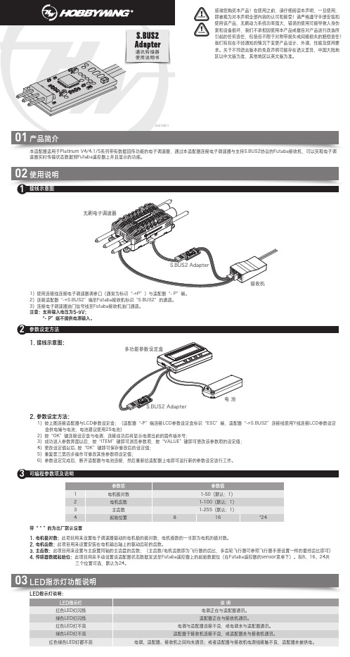
通讯转接器使用说明书接线示意图1参数设定方法2可编程参数项及说明3LED指示灯说明:1. 接线示意图:2. 参数设定方法:1)按上图连接适配器与LCD参数设定盒;(适配器“-P”端连接LCD参数设定盒标识“ESC”端,适配器“-+S.BUS2”连接线使用Y线连接LCD参数设定 盒供电端与电池,电池建议使用2S电池)2)按“OK”键连接设定盒与电调,连接成功后将显示电调当前的固件版本号;3)成功进入参数界面以后,按“ITEM”键即可浏览参数项,按“VALUE”键即可更改该参数项的设定值; 4)更改设定值以后, 按“OK”键即可保存修改后的设定值; 5)重复第三第四步操作可修改其他参数项设定值;6)参数设定完成后,断开适配器与电池连接,然后重新给适配器上电即可运行新的参数设定进行工作。
带“ * ”的为出厂默认设置1. 电机极对数:此项目用来设置电子调速器驱动的电机极的极对数;电机极数的一半即为电机的极对数。
2. 电机齿数:此项目用来设置安装在电机输出轴上的驱动齿轮的齿数。
3. 主齿数:此项目用来设置与主旋翼同轴的主齿盘的齿数;(主齿数/电机齿数即为飞行器的齿比,多齿轮飞行器可参照飞行器手册设置一样的最终齿比即可)4. 传感器数据起始位:此项目用来手动设置该适配器状态数据发送至Futaba遥控器上的起始数据位(在Futaba遥控器的sensor菜单下)。
有8、16、24共 三个位置可选,默认为24。
1)使用连接线连接电子调速器调参口(通常为标识“-+P”)与适配器“- P”端。
2)连接适配器“-+S.BUS2”端至Futaba接收机标识“S.BUS2”的通道。
3)连接电子调速器油门信号线至Futaba接收机油门通道。
注意:支持输入电压为5-9V; “- P”端不提供电源输入。
03LED指示灯功能说明。
04-PWM、PPM、S.bus与DSM2接线方式解析

PWM、PPM、S.bus与DSM2接线方式解析一、PWM1、PWM的含义PWM ,Pulse Width Modulation的缩写,英文意思是脉宽调制,在航模中主要用于舵机的控制。
这是一种古老而通用的工业信号,是一种最常见的控制信号。
该信号主要原理是通过周期性跳变的高低电平组成方波,来进行连续数据的输出。
如下图所示:Paste_Image.png而航模常用的PWM信号,其实只使用了它的一部分功能,就是只用到高电平的宽度来进行信号的通信,而固定了周期,并且忽略了占空比参数。
PWM的优点很明显:由于传输过程全部使用满电压传输,非0即1,很像数字信号,所以他拥有了数字信号的抗干扰能力。
脉宽的调节是连续的,使得它能够传输模拟信号。
PWM信号的发生和采集都非常简单,现在的数字电路则使用计数的方法产生和采集PWM信号。
信号值与电压无关,这在电压不恒定的条件下非常有用,比如电池电压会随消耗而降低,DCDC都会存在纹波等等,这些因素不会干扰信号的传输。
2、PWM通信协议高电平有效。
高电平电压:常见4.8~6V,也有使用3.3V 和更高电压的,要看舵机的承受能力。
信号周期:常见50Hz和300Hz两种,前者被称为模拟舵机,后者被称为数字舵机。
注意纠正一个概念,舵机的模拟和数字之分其实指的是信号采集器,是使用模拟电路还是使用数字电路,跟信号频率无关,当然数字采集器的采集能力较强,所以频率可以高一些。
但是随着技术进步,现在即使买50Hz的舵机也同样使用数字电路进行信号采集,哪里来的模拟舵机呢?建议大家忘记这两个词汇吧。
脉宽宽度:50Hz信号多用于老式舵机,是上个世纪舵机的主要控制信号形式,其脉宽宽度为0.5ms至2.5ms。
300Hz 信号则是目前使用的最广泛的信号形式,其波形速度快,每秒可以传输300次,所以相应的脉宽也有所减小为0.9ms至2.1ms。
两种舵机控制信号如下图所示:50hz与300hz的PWM控制信号与角度关系PPM二、什么是PPMPWM信号被广泛用于舵机控制,但是它有一个明显的缺陷,就是有多少个舵机就需要多少个控制线路。
KS-servo 2.4 ghz FASST 兼容接收机 FM800 说明书
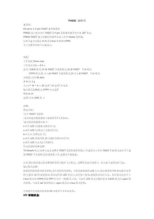
FM800说明书兼容性:KS-servo2.4ghz FASST兼容接收机FM800设计使用双叶FASST2.4ghz发射器和兼容双叶新LBT协议.FM800FASST最小和最轻的兼容市场上所有futaba遥控器,仅重2g,可以输出8ch的s-bus和8ch CPPM,专门为微型四轴飞行器设计。
规格:工作电流:50ma max工作电压:3.6~8.4v延迟:S.BUS模式:14@FASST多通道模式,16@FASST7ch模式CPPM模式:21女士@FASST多通道模式,24女士@FASST7ch模式灵敏度:大约-90dbm重量:约2g大小:l*W*H=30毫米*14毫米*3毫米输出模式:S.BUS或CPPM可以选择频道:8ch范围:全部1000米+设置:绑定过程:·打开FASST发射机·电池连接到接收器按下接收机的F/S按钮。
·既导致的连续循环如下:o红色LED灯(搜索无线电信号)o绿色LED灯(收到了无线电信号)o红灯灭了(绑定好了)o绿色LED持续闪烁10次(ID存储在内存中)o绿色LED灯长亮(正常操作)自动防故障装置设置:TX-failsafe特点:这种方法是设置在FASST发射机故障保险(工作通道3只有在FASST7ch模式或在多个通道FASST多渠道模式)在接收机工作,就像双叶接收器。
注意:我们强烈建议你设置故障保险功能在飞行模式。
设置时需要关闭油门,防止起飞或则失控飞走。
输出模式设置:如果你的接收机连接发射机,请关闭你的发射机。
当你的接收器的LED灯红,按住接收机F/S按钮超过6秒钟,不超过10秒,释放按钮,看到绿色的LED闪光灯,再次按下按钮,接收机回到红灯亮。
现在模式状态介于s-bus模式和CPPM(连续PPM信号在一线)模式之间。
当绿色LED闪光灯慢闪表明S.BUS模式向cppm模式转换。
当绿色led快闪则表示cppm模式向s-bus模式转换。
04 PWM、PPM、S.bus与DSM2接线方式解析

PWM、PPM、S.bus与DSM2接线方式解析一、PWM1、PWM的含义PWM ,Pulse Width Modulation的缩写,英文意思是脉宽调制,在航模中主要用于舵机的控制。
这是一种古老而通用的工业信号,是一种最常见的控制信号。
该信号主要原理是通过周期性跳变的高低电平组成方波,来进行连续数据的输出。
如下图所示:Paste_Image.png而航模常用的PWM信号,其实只使用了它的一部分功能,就是只用到高电平的宽度来进行信号的通信,而固定了周期,并且忽略了占空比参数。
PWM的优点很明显:由于传输过程全部使用满电压传输,非0即1,很像数字信号,所以他拥有了数字信号的抗干扰能力。
脉宽的调节是连续的,使得它能够传输模拟信号。
PWM信号的发生和采集都非常简单,现在的数字电路则使用计数的方法产生和采集PWM信号。
信号值与电压无关,这在电压不恒定的条件下非常有用,比如电池电压会随消耗而降低,DCDC都会存在纹波等等,这些因素不会干扰信号的传输。
2、PWM通信协议高电平有效。
高电平电压:常见4.8~6V,也有使用3.3V 和更高电压的,要看舵机的承受能力。
信号周期:常见50Hz和300Hz两种,前者被称为模拟舵机,后者被称为数字舵机。
注意纠正一个概念,舵机的模拟和数字之分其实指的是信号采集器,是使用模拟电路还是使用数字电路,跟信号频率无关,当然数字采集器的采集能力较强,所以频率可以高一些。
但是随着技术进步,现在即使买50Hz的舵机也同样使用数字电路进行信号采集,哪里来的模拟舵机呢?建议大家忘记这两个词汇吧。
脉宽宽度:50Hz信号多用于老式舵机,是上个世纪舵机的主要控制信号形式,其脉宽宽度为0.5ms至2.5ms。
300Hz 信号则是目前使用的最广泛的信号形式,其波形速度快,每秒可以传输300次,所以相应的脉宽也有所减小为0.9ms至2.1ms。
两种舵机控制信号如下图所示:50hz与300hz的PWM控制信号与角度关系PPM二、什么是PPMPWM信号被广泛用于舵机控制,但是它有一个明显的缺陷,就是有多少个舵机就需要多少个控制线路。
航模遥控协议
航模遥控协议航模遥控协议是指在航模飞行过程中,遥控器与飞行器之间的通信协议。
它是航模飞行的基础,对于飞行器的稳定性和飞行性能起着至关重要的作用。
本文将介绍航模遥控协议的基本原理、常见的协议类型以及在实际飞行中的应用。
首先,我们来了解一下航模遥控协议的基本原理。
遥控器通过无线电信号发送控制指令,飞行器接收并解析这些指令,从而实现飞行器的控制。
在这个过程中,遥控器和飞行器之间需要建立稳定的通信连接,以确保指令的准确传输和执行。
因此,航模遥控协议需要具备良好的抗干扰能力和高效的数据传输速率,以应对复杂的飞行环境和快速变化的控制需求。
在实际应用中,航模遥控协议通常采用频率调制(FM)或脉冲宽度调制(PWM)等技术来实现数据的传输。
频率调制是指通过改变无线电信号的频率来传输数字信号,而脉冲宽度调制则是通过改变脉冲信号的宽度来传输数字信号。
这两种技术各有优缺点,可以根据具体的应用场景选择合适的协议类型。
除了基本的通信原理外,航模遥控协议还需要考虑飞行器的控制需求和飞行环境的特点。
不同类型的飞行器可能需要不同的控制指令,例如固定翼飞机需要控制油门、方向舵和升降舵,而多旋翼飞行器则需要控制电机转速和姿态角度。
此外,飞行环境的特点也会影响到航模遥控协议的设计,例如在复杂的电磁环境中,需要采用抗干扰能力强的协议类型,以确保稳定的通信连接。
在实际飞行中,航模遥控协议的稳定性和可靠性对飞行器的安全性和飞行性能至关重要。
因此,在选择和使用航模遥控协议时,需要充分考虑飞行器的类型和应用场景,以确保协议能够满足飞行器的控制需求并具备良好的抗干扰能力。
同时,还需要注意遥控器和飞行器之间的通信距离和通信质量,以确保稳定的通信连接和可靠的控制指令传输。
总之,航模遥控协议是航模飞行的基础,对飞行器的控制和飞行性能起着至关重要的作用。
在实际应用中,需要根据飞行器的类型和应用场景选择合适的协议类型,并注意保证通信连接的稳定性和可靠性。
只有这样,才能确保飞行器能够安全、稳定地进行飞行,实现各种飞行动作和任务。
S.BUS2端口至S.BUS2端口的接线示例说明书
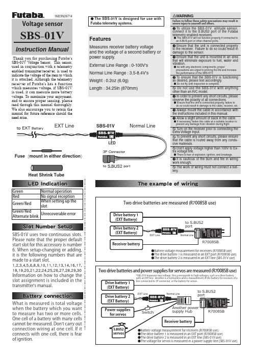
SBS-01VHeat Shrink TubeNormal LineEXT LineSBS-01V V oltage Sensor. This sensor, used in conjunction with a telemetry enabled transmitter/receiver, is used to indicate the voltage of the item to which it is attached. Although the telemetry receiver of Futaba's has a function which measures voltage, if SBS-01V is used, it can measure more battery voltage. To maximize your enjoyment, and to ensure proper sensing, please read through this manual thoroughly. We also encourage you to retain the manual for future reference should the need arise.●The SBS-01V is d esigned for use withFutaba telemetry systems.Green Normal operation Red No signal reception Green/RedWhen setting up the slotGreen/RedAlternate blinkUnrecoverable errorFeaturesMeasures receiver battery voltage and the voltage of a second battery or power supply.External Line Range : 0-100V's Normal Line Range : 3.5-8.4V's Weight : 0.2oz (6.0g) Length : 34.25in (870mm)Please note that the proper default start slot for this accessory is number 6. When setup-changing or adding, it is the following numbers that are made to a start slot.1,2,3,4,5,6,8,9,10,11,12,13,14,16,17,18,19,20,21,22,24,25,26,27,28,29,30Information on how to change the slot assignment is included in the transmitter's manual.when the battery which you want to measure has two or more cells. One cell of a battery with many cells cannot be measured. Don't carry out connection wiring at one cell. If it connects with one cell, there is fear of ignition.Measure the cable and then cut it to the desired length.Cut approximately 30mm of the negative (-, black) line from the cable.Solder the fuse inline on the negative wire and then reattach the section of wire that was previously removed. The fuse should be attached as close to the external power supply as possible.Place a piece of heat shrink tubing over the fuse, ensuring that it covers the soldered areas. Shrink the tubing snug to the fuse and the wire using a heat gun.The cable should be connected as shown in the diagram below. The cable gets connected to the wires that come off the ESC and connect to the battery.The manual for the Telemetry system should be referred to after the setup is complete; checking to make sure it functions as desired and that it provides the correct voltage on the display.Fuse to Black line (-)To MotorFUTABA CORPORATION1080 Yabutsuka, Chosei-mura, Chosei-gun, Chiba-ken, 299-4395, JapanPhone: +81 475 32 6982, Facsimile: +81 475 32 6983©FUTABA CORPORATION 2012, 10 (1)。
航模遥控器通信协议
航模遥控器通信协议篇一:航模遥控器原理飞机模型的无线电遥控,是指利用无线电波传送操作者对模型动作的指令模型根据指令做出各种飞行姿态。
用无线电技术对模型进行飞行控制的史,可以追溯到第二次世界大战以前。
不过,由于当时民间。
用无线电制航模面临十分复杂的法律手续,而且当时的遥控设备既笨重又极不可,因此,遥控航模未能推广开来到了本世纪60年代初期,随着电子技术发展,各种应用于航模控制的无线电设备也开始普及,时至今日,无线遥控设备已广泛地用于各种航空、航海和陆上模型。
本文介绍的“塞斯纳”177飞机模型套件材料中,配置的是四通道比例遥控设备系统,它由发射机、接收机、舵机、电源等部分组成。
图l所示的,是4通道比例遥控设备发射机的外型和各部分名称。
在发射机的面板上,有两根分别控制l、2通道和3、4通道动作指令的操纵秆,以及与操纵杆动作相对应的4个微调装置。
在发射机底部,设置有4个舵机换向开关,分别用于变换舵机摇臂的偏转方向。
图2所示的,是接收机和舵机以及接收机电源装置,其中接收机用来接收从发射机传来的指令信号,经处理后,指挥舵机作出与发射机指令相对应的动作。
电池组给接收机和舵机提供工作能源,它由4节普通5号干电池串联而成。
所谓比例控制,简单说来,就是当我们把发射机上的操纵杆由中立位置向某一方向偏移一角度时,与该动作相对应的舵机摇臂也同时偏移相应的角度,舵机摇臂偏转角度与发射机操纵杆偏移角度成比例.图3显示了发射机执行舵机与飞机模型舵面的动作关系。
当发射机操纵杆(或对应的微调杆)往左、右偏转或回复中立时,执行舵机的摇臂也随之相应地往左、右偏转或回复中立,带动模型的舵面往左,右偏转或回复中立,操纵杆(或微调杆)、舵机摇臂、模型舵面偏转的角度大小成比例。
4通道的比例遥控设备,可以同时对模型进行四个不同动作(例如油门、升降舵,方向舵,副翼)的比例控制。
这样的控制已十分接近载人飞机的操纵了。
因此,如果能熟练地运用遥控设备和充分地掌握模形飞行的原理,经过一段时间的刻苦练习,操纵者可象驾驶载人飞机一样控制模型在天空自由飞翔。
四光吊舱用户手册说明书
ZT30四光吊舱4K AI高分热成像激光测距用户手册V1.02023.5感谢您购买思翼科技的产品。
ZT30是一款四传感器混合吊舱,变焦相机、热成像相机、激光测距仪、广角相机高效协同。
搭载640*512级别高分辨率热成像传感器、1200米级别高精度激光测距、180倍混合变焦和30倍光学变焦(1/2.7英寸索尼CMOS支持4K级别视频录制与拍照)、2K超广角、基于神经网络处理器的强大AI跟踪识别功能、航向轴无限旋转、升级版减震快拆结构、丰富的云台控制接口可以兼容思翼链路和第三方链路产品、高精度高协同控制算法在飞行中保持稳定的变倍和成像效果,是多旋翼无人机、垂起无人机以及智能机器人等领域不可多得的优质挂载。
也为了带给您良好的产品使用体验,请您在装机、飞行前仔细查阅用户手册。
本手册可以帮助您解决大部分的使用疑问,您也可以通过访问思翼科技官方网站()与产品相关的页面,致电思翼科技官方售后服务中心(400-838-2918)或者发送邮件到****************直接向思翼科技工程师咨询产品相关知识以及反馈产品问题。
思翼科技官方QQ群阅读提示 (6)标识、图标 (6)安全 (6)设备闲置、携带、回收 (7)1产品简介 (8)1.1产品特性 (8)1.2部件说明 (13)1.2.1产品概览 (13)1.2.2接口定义 (15)1.3技术参数 (16)1.4物品清单 (20)1.5状态指示灯定义 (21)2使用前 (22)2.1安装与固定 (22)2.2连接与供电 (23)3云台控制 (24)3.1思翼手持地面站配合“SIYI FPV”或思翼QGC(安卓)应用控制思翼光电吊舱/云台相机 (24)3.1.1准备工作 (24)3.1.2云台俯仰与平移 (26)3.1.3变倍、变焦与对焦 (26)3.1.4拍照与录像 (27)3.2通过S.Bus信号控制云台(以MK15遥控器为例) (27)3.2.1准备工作 (28)3.2.2云台俯仰(以MK15左右拨轮控制为例) (30)3.2.3变倍、变焦与对焦(以MK15开关控制为例) (31)3.2.4拍照与录像(以MK15按键控制为例) (32)3.3UART/UDP控制(通过SDK支持) (33)3.3.1SDK协议格式说明 (33)3.3.2SDK通讯命令 (33)3.3.3SDK通讯接口 (41)3.3.4SDK通讯数据示例 (42)3.3.5SDK CRC16校验代码 (44)3.3.6思翼云台SDK集成开发进阶说明 (45)3.4思翼HM30高清图传配合思翼QGC(Windows)软件控制思翼吊舱或云台相机503.4.1准备工作 (50)3.4.2云台俯仰与平移 (52)3.4.3变倍、变焦与对焦 (53)3.4.4拍照与录像 (53)3.5通过UART窗口配合Ardupilot驱动控制思翼吊舱或云台相机 (54)4视频输出 (57)4.1单相机流、单画面 (57)4.2双相机流、拼接画面 (57)4.3双相机流、大小窗口 (58)4.4三相机流、拼接画面、大小窗口 (58)4.5通过思翼手持地面站显示视频 (59)4.6通过HM30高清图传在安卓设备上显示视频 (59)4.7通过HM30高清图传在Windows设备上显示视频 (61)4.8通过网口直连Windows设备显示视频 (62)4.9思翼云台相机通过网口输出视频到第三方链路 (64)4.10无法显示视频图像的解决方法 (65)4.10.1在移动设备显示 (65)4.10.2在Windows设备显示 (67)4.11设备常用参数 (68)5“SIYI FPV”应用 (70)5.1设置菜单 (72)5.2链路信息 (73)5.3云台相机 (74)5.4关于SIYI FPV (76)6固件升级与调参 (77)6.1云台、变焦固件升级 (77)6.2相机固件升级 (79)6.3云台相机调参 (81)6.3.1通道配置 (81)6.3.2相机配置 (83)6.3.3云台校准 (84)7售后与保修 (88)7.1返修流程 (88)7.2保修政策 (89)7.2.17天包退货 (89)7.2.215天免费换货 (90)7.2.3一年内免费保修 (92)阅读提示标识、图标在阅读用户手册时,请特别注意有如下标识的相关内容。
sbus 协议
sbus 协议Sbus 协议。
Sbus(Serial Bus)是一种串行总线通信协议,广泛应用于遥控器和接收机之间的通讯。
它采用了串行通信的方式,能够在单根信号线上同时传输多个通道的数据,具有高速传输、抗干扰能力强等优点,因此在遥控器行业得到了广泛的应用。
Sbus 协议的特点之一是高速传输。
相比于传统的PPM(Pulse Position Modulation)信号,Sbus 信号的传输速率更快,能够在同样的时间内传输更多的数据,这使得遥控器能够更精准地捕捉到操作者的指令,提高了遥控器的响应速度和控制精度。
除此之外,Sbus 协议还具有抗干扰能力强的特点。
由于采用了串行通信的方式,Sbus 在传输过程中能够更好地抵御外部干扰,保证数据传输的稳定性和可靠性。
这对于遥控器而言尤为重要,因为遥控器往往需要在复杂的环境中进行控制,如无人机在飞行中受到风的影响,需要遥控器能够稳定地传输指令,以保证飞行的安全性。
此外,Sbus 协议还支持多通道数据传输。
传统的遥控器通常只能传输少量的通道数据,而Sbus 协议则能够在同一根信号线上同时传输多个通道的数据,这使得遥控器能够更灵活地控制各种设备,如多旋翼飞行器、航模飞机等,满足了不同设备对通道数量的需求。
在实际应用中,Sbus 协议已经成为了遥控器行业的主流通讯协议之一。
各大遥控器厂商纷纷推出了支持Sbus 协议的遥控器和接收机产品,以满足市场对高速、稳定、多通道数据传输的需求。
总的来说,Sbus 协议作为一种串行总线通信协议,在遥控器行业具有着诸多优势,如高速传输、抗干扰能力强、多通道数据传输等,已经成为了遥控器行业的主流通讯协议之一,为遥控器的性能提升和应用拓展提供了重要的支持。
随着技术的不断发展,相信Sbus 协议在遥控器行业的地位会越来越重要,也会在更多的领域得到应用和推广。
sbus协议

sbus协议S.Bus(Serial Bus)是由Futaba公司开发的串行通信协议,用于遥控器与接收机之间的通信。
S.Bus协议能够将所有遥控通道的信息通过一个串行信号进行传输,减少了接线数量,提高了系统的可靠性和稳定性。
S.Bus协议采用了串行异步通信的方式,每个通道的信息以二进制码的形式进行传输。
通道信息的传输分为两个部分:帧头和通道数据。
帧头由起始位、起始位延时、帧头延时、数据位以及数据位的延时组成。
起始位用于识别帧头开始的位置,起始位延时和帧头延时用于保证整个帧的同步,数据位用于传输通道数据,数据位的延时用于保证数据传输的可靠性。
S.Bus协议的一个特点是,它可以在一个信道上同时传输多个通道的数据。
这是通过将每个通道的二进制数据串行地发送到一个共享的信道上实现的。
接收机可以根据数据位的顺序来识别每个通道的数据,实现多通道数据的解析和还原。
这样的设计既减少了接线数量,也提高了数据传输的效率和可靠性。
S.Bus协议的数据传输速率和帧率是可以调整的,一般情况下,数据传输速率为100Kbps,帧率为约16ms。
这意味着每隔16ms,遥控器会向接收机发送一帧数据,接收机则根据这些数据控制相应的执行器或设备。
通过调整数据传输速率和帧率,可以适应不同的应用场景和需求。
除了传输通道数据,S.Bus协议还支持传输其他控制信息,例如飞行器的模式切换、功能开关、设备配置等。
这些额外的控制信息可以通过特定的通道进行传输,提供更多的操作和调整选项。
S.Bus协议适用于许多领域的应用,特别是在无人机和遥控车辆领域。
由于S.Bus协议能够同时传输多个通道的数据,对于需要精准和快速控制的应用非常适用。
而且,S.Bus协议的稳定性和可靠性也使其成为无人机和遥控车辆等领域的首选通信协议。
总之,S.Bus协议是一种高效、可靠的串行通信协议,适用于遥控器与接收机之间的通信。
它通过串行传输多个通道的数据,减少了接线数量,提高了系统的可靠性和稳定性。
T21一体遥控器说明书-V1.2.1
物品清单
主要模块
接收机 ×1
遥控器 x 1
配件
供电线
为接收机设备供电(DC:7.4-12V, 锂电池 2s-3s)
充电器
用于为遥控器充电。
接收机对频线 ×1
用于接收机重新对频与设置参数
产品说明
4
双 S-BUS 接收机部件名称
②④ 1
⑦
⑥
⑧
⑨
⑤
③
①供电接口
使用 XT30 供电头,供电电压为:7.4-12V
安装注意........................................................................................................ 3 使用注意........................................................................................................ 3 简 介....................................................................................................................... 4 物品清单................................................................................................................. 4 产品说明................................................................................................................. 4 双 S-BUS 接收机部件名称............................................................................5 遥控器部件名称............................................................................................ 6 接收机安装连线............................................................................................ 7 遥控器操作............................................................................................................. 8 平板电脑开机和关机.................................................................................... 8 遥控器开机和关机........................................................................................ 8 遥控器低电量报警和摇杆长时间未工作报警........................................... 8 遥控器及接收机指示灯说明........................................................................9 遥控器调参软件的使用....................................................................................... 10 主界面说明.................................................................................................. 10 通道监控与校准.......................................................................................... 10 通道配置...................................................................................................... 12 通道保持...................................................................................................... 15 油门保持...................................................................................................... 16 接收机配对和配置............................................................................................... 17 遥控器充电........................................................................................................... 20 常见问题............................................................................................................... 20 固件升级操作步骤............................................................................................... 21 遥控器端固件升级...................................................................................... 21 接收机端固件升级...................................................................................... 22 产品规格............................................................................................................... 23
SMBus+2.0中文协议

4.第二层——数据链路层4.1 比特传输SMBus在总线上分别使用固定的电压来表示逻辑1和逻辑0。
4.1.1.数据有效性图4-1 数据有效性在时钟高电平阶段,SMBDAT上的数据必须保持稳定。
当SMBCLK为低时,数据才可以变化。
图4-1表明了这种关系。
实际的规范请参考图3-1和表1。
4.1.2 开始和结束条件图4-2:开始和结束条件两种独特的总线状态定义了信息传输的开始和结束条件。
1.在SMBCLK为高时,SMBDAT由高到低的跳变表示信息传输的开始条件2.在SMBCLK为高时,SMBDAT由低到高的跳变表示信息传输的开始条件。
开始和结束条件并不总是由总线主器件产生的。
在开始条件产生后,总线就被认为处于忙碌状态。
当出现结束条件或SMBCLK和XMBDAT两条线维持在高电平的时间超过THIGH:MAX后,总线处于闲置状态。
4.1.3. 总线闲置条件总线闲置是一种在以下较小的那个时间内,SMBCLK和XMBDAT两条线都处于高电平而没有任何状态变化的状态。
●检测到上一个结束条件,经过TBUF(4.7μS)以后,或者●T HIGH:MAX(50μS)后一个时间参数考虑了如下的情况:一个主器件被动态地加到总线上,而且可能没有检测到SMBCLK和XMBDAT上状态的变化。
这时,主器件必须等待足够长的时间来保证当前总线上没有数据传输。
4.2 SMBus上的数据传输图4-3:SMBus字节格式每个字节包含八个比特。
在总线上每个字节传输完都必须紧跟一个确认比特。
字节在传输时都都先传送最高位(MSB)下面的图,图4-4表明了确认脉冲(ZCK)和不确认脉冲(NACK)相对于其他数据的位置。
图4-4:SMBus的ACK和NACK信号由主器件产生这个与确认信号有关的时钟。
发送端(也就是主器件或者从器件)确认这个时钟周期释放SMBus数据线(SMBDAT为高)。
为了确认一个字节,接收端必须在时钟脉冲的高电平阶段,根绝SMBus的时序规范,将SMBDAT拉到低。
S-Bus类型的电子模块说明书

PCD1.B5010-A20E-Line S-Serie RIO 6DI 24V, 3RelData sheetDimensions and installationf S-Bus protocol optimized for fast data exchangef Modbus protocol for integration in multi-vendor installations*f Local override operating level via web panel or buttons on the module f Easy programming using the FBox library and web templates f Industrial hardware design f Pluggable terminal blocksf Bridge connectors for power supply and communication f Bus termination on boardf Configurable Bi-Colour LEDs and labelling for I/Os* B y default the module is working in S-Bus Data Mode with Autobaud detection. To configure Modbus the Windows based Application “E-LineApp” is required.FeaturesOn a 35 mm top-hat rail ( i n accordance with DIN EN 60715 TH35)General technical dataPower supply The S-Serie E-Line RIO modules are controlled via the RS-485 serial communication protocols S-Bus and Modbus for decentralised automation using industrial quality components. The data point mix is specifically designed for building automation applications.The compact design according to DIN 43880 enables the use in electrical distributionboxes even in the most confined spaces. Installation and maintenance are facilitated by the local manual override for each output. Remote maintenance is also possible using the access to the manual override by the web interface in the Saia PCD® controller. Programming is very efficient and fast using a complete FBox library with web templates for S-Bus. Individual programs may directly access the data points via Registers and Flags, a complete documentation is available from this data sheet.Housing width 6 HP (105 mm)Compatible with electrical control cabinet (in accordance with DIN 43880, size 2 × 55mm)/DA+DB-GND+24VOpenClose For easy installation the power supply and communicationbus is available together at one connector. The push-in springterminals enable wiring as well support the connector bridge.Push-in spring terminals enable wiring with rigid or flexible wireswith a diameter up to 1.5 mm². A max. of 1 mm² is permitted withcable end sleeves.Terminal technologyConnection conceptOFF No PowerGreen Communication OKGreen blink Auto bauding in progressOrange No communicationRed ErrorRed/Green alternate B ooter mode(e.g. during Firmware download)Red blink Internal fatal errorStatus LEDThe module provides an active bus termination. It is switchedoff by factory default. To enable the termination, the switchneed to be in the “Close” position.Bus terminationThe USB interface provides access to the communicationprotocol configuration. Firmware updates can also be downloaded via Saia PG5® Firmware Download tool.Service interfaceReset buttonPushed over 20 seconds: The button needs to be pushed forminimum 20 seconds and released during the first minute afterpower up. All user settings are reset to factory default values.Pushed at power up: Power off the device and press thebutton. Power on and release the button before 5 seconds havepassed. The device stays in boot mode for further actions likefirmware download etc.Input/output configurationAssignment overviewThe inputs are galvanically isolated ..GND +24V/DA+DB–GND +24V/DA+DB–Connection diagramsDigital inputs24 V AC/DCRelay outputDigital outputSource operationPower supply and bus terminationOFF No Power Green Communication OK Green blink Auto bauding in progress Orange No communication Red Error Red/Green alternate B ooter mode(e.g. during Firmware download)Red blink Internal fatal errorStatus LEDLED SignalisationThe Output indication LED can be configured in colour and blink code separately for output state Low and High.LED colour f Off f Red f Green*f Orange (red + green)LED blink codef No blink*f Slow blinking (0.5 flashes per second) f Fast blinking (2 flashes per second)*Factory defaultDigital outputThe Manual override LED is Off in automatic mode and orange in case of manual override is active. LED colour f Off (automatic)f Orange manual mode active LED blink codef No blink (local manual override)f Blinking 1 flash per second (remote manual override)Manual modef Data exchange for I/O via optimised S-Busf Configurable save state for bus interruption or timeoutf Direct generation of the symbolsf Reading and writing of the status of the manual override statusf Direct compatibility with web macrosThe modules are addressed and programmed with Saia PG5® Fupla FBoxes. Web templates are available for theoperation and visualisation of the manual override function.Further information, including which FBoxes are supported,Getting Started, etc., can be found on our support page.Web templates are available for the operation and visualisationof the manual override function.Communication FBoxWeb templatesProgrammingBy using the local override function, commissioning can takeplace independently of the master station.In addition, the manual operation can also be controlledremotely using a touch panel. If the bus line is cut off, the E-Line libraryFuplafrom the E-Line library. Mixed mode operation is not recommended.E-Line RIOs support the device setup by a windows application program connected via USB. The installer is available for down-load from the SBC support page: E-Line RIO IO Modules.The Baudrate can be defined as automatic detection(default) or set to a specific value. The drop down choice willbe available when the check box “Automatic” is unchecked.TN delay and TS delay shall be left at their default values of 2.Create a new device configurationOpen an existing device configurationSave the current settings as device configurationUpload configuration from the deviceDownload settings to the deviceThe serial communication protocol can be defined either asS-Bus or Modbus. By default the modules are delivered fromfactory with S-Bus.S-Bus settingsThe station number can be set by the rotary switches at thedevice in the range of 0 … 98. If the rotary switches are set toposition 99 the station number can be defined by the deviceconfiguration in a range of 0 … 253.Modbus settingsThe Baudrate is set by default to 115 k. It can be defined aschoice of the list.For best interoperability the Parity Mode and number ofStop Bits can also be set.S-Bus communication is based on Saia PCD® S-Bus Data Mode. Only the set-up of a unique S-Bus address within the communi-cation line is required to establish a communication between Saia PCD® controllers and E-Line RIO modules. The address can be set by the rotary switches at the front of the module. The baud rate will be learned from the network by factory default. In addition a Windows based application is available for manual parameter setup. Configuration parameters as well as manual override state and value are saved non-volatile. A delay of about one second between a manual state change and none volatile saving has to be taken into consideration.Device address f 0 … 98 Address is taken from the rotary switchesf 99Address is taken from the device configuration. The address is settable with the E-Line configuration software.Start-up procedure f Reboot: All outputs are cleared (Off state) f < 1 sec.Output in manual operation are set according to the state before power down.f Outputs in automatic modeIs no telegram received after reboot within the “safe state power-on timeout” the module enters into the safe state mode and sets the outputs according to their configured values.On reception of a valid command telegram the outputs are controlled by the communication. When no communication update followed within the “safe state com. timeout” the module enters into safe state and sets the outputs according to their configured values.Usage of the E-Line module specific FBoxesThe usage of the E-Line module specific FBoxes from the E-Line S-Bus Fupla library allows an easy and efficient commissioning of the E-Line RIO.The FBox allow to define and configure all possible functionalities of the E-Line RIO like manual override permission, usage of safe state mode, behaviour and colour of the LED’s and so on.In the background, the FBox does use the fast ‘E-Line S-Bus’ protocol for a high speed communication between the master and the RIO.The following chapter describes the media and parameter mapping to Registers and Flags for individual programming. For efficient PCD programming the E-Line RIO FBox family and templates are suitable for most applications. Only individual pro-gramming (e.g. Instruction List) require standard S-Bus communication.Digital inputs Normal operation: The outputs are set according the flag set by the communication.Manual operation: The output are set according to the manual command, the communication flags are ignored. Safe State: In case of a broken communication, a safe state value can be applied, see table Safe State Configuration. Register format for manual override via S-Bus (Reg. 90 … 92): Bit 0 Current output value Bit 30 1: output is driven in manual override by S-Bus Bit 31 1: output is driven in manual override by local push buttons Register format for local manual override (Reg. 93 … 95): Bit 0 Current output value Bit 311: output is driven in manual override by local push buttons** W riting to these registers has no effect. Used only if hardware permission is set in the configurationDirect access to the RIO media with standard S-Bus send and receive telegramsThe LEDs can be configured individually depending on the I/O state in colour and blink code.LED ConfigurationRegister format:Bit 0 ... 7 I/O state Low LED colour Bit 8 ... 15 I/O state Low LED blink code Bit 16 ... 23 I/O state High LED colour Bit 24 (31)I/O state High LED blink codeLED colour 0: Off1: Red2: G reen 3: Orange (red + green)LED blink code 0: No blink 1: Slow blinking (0.5 flashes per second) 2: Fast blinking (2 flashes per second)Factory default: Low: off, High: LED colour 2 (green), no blinkConfiguration for safe state and manual overrideManual operation mode:f Disabled (0)f Local operation only (4, Bit 2 set)f Local operation enabled, remote limited (6, Bit 1 and 2 set), defaultf Local and remote operation enabled (12, Bit 2 and 3 set)f Remote operation only, local operation disabled (8, Bit 3 set)The safe state enable flag and the safe state value are combined in the following way: Setting the enable flag to 0 keep the output value unchanged in case of safe state occurrence.Setting the enable flag to 1 writes the safe state value in case of safe state occurrence.Device Information*** The four registers contain the ASCII characters of the product type.E.g. for PCD1.A2000-A20:0605: 50434431H 0606: 2E413230H 0607: 30302D41H 0608: 32300000HModbus fulfils the requirements for standard communication protocols. It is based on Modbus RTU. The Windows based configu-ration software is required to enable and set up the Modbus communication parameters. The device address can be set up with the rotary switches at the front of the module. Configuration parameters as well as manual override state and value are saved non-volatile. A delay of about one second between a manual state change and non-volatile saving has to be taken into consideration. Device addressf0 … 98 Address is taken from the rotary switchesf99 Address is taken from the device configuration. The address is settable with the E-Line configuration soft-ware.Start-up proceduref Reboot: All outputs are cleared (Off state)f<1 sec. Output in manual operation are set according to the state before power down.f Outputs in automatic modeIs no telegram received after reboot within the “safe state power-on timeout” the module enters as will intothe safe state mode and sets the outputs according to their configured values.On reception of a valid command telegram the outputs are controlled by the communication. When no com-munication update followed within the “safe state com. timeout” the module enters into safe state and setsthe outputs according to their configured values.The following chapter describes the media and parameter mapping to Registers and Flags (=Coils).Supported Modbus services:f Function code 1 (read outputs)f Function code 3 (read registers)f Function code 15 (write multiple outputs)f Function code 16 (write multiple registers)The CRC has to be calculated over all telegram bytes starting with address field up to the last data byte. The CRC has to be attached to the data. Please find an example at the appendix of this document. For more details, please refer the publicly available Modbus documentation .Normal operation: The outputs are set according the flag set by the communication.Manual operation: The output are set according to the manual command, the communication flags are ignored.Safe State: In case of a broken communication, a safe state value can be applied, see table Safe State Configuration.Register format for manual override via Modbus (Reg. 180 … 185):Bit 0 Current output value Enable Reg. Bit 14 1: output is driven in manual override by Modbus Enable Reg. Bit 15 1: output is driven in manual override by local push buttons Register format for local manual override (Reg. 186 … 191):Value Reg. Bit 0 Current output value Enable Reg. Bit 15 1: output is driven in manual override by local push buttonsThe LEDs can be configured individually depending on the I/O state in colour and blink code.** Writing to these registers has no effect. Used only if hardware permission is set in the configurationRegister format:Output L, Bit 0 … 7 I/O state Low LED colour Output L, Bit 8 … 15 I/O state Low LED blink code Output H, Bit 0 … 7 I/O state High LED colour Output H, Bit 8 … 15 I/O state High LED blink codeLED colour 0: Off 1: Red 2: Green3: Orange (red + green)LED blink code 0: No blink1: Slow blinking (0.5 flashes per second)2: Fast blinking (2 flashes per second)Factory default:L ow: off,High: LED colour 2 (green), no blinkConfiguration for safe state and manual overrideManual operation mode:f Disabled (0)f Local operation only (4, Bit 2 set)f Local operation enabled, remote limited (6, Bit 1 and 2 set), defaultf Local and remote operation enabled (12, Bit 2 and 3 set)f Remote operation only, local operation disabled (8, Bit 3 set)The safe state enable flag and the safe state value are combined in the following way: Setting the enable flag to 0 keep the output value unchanged in case of safe state occurrence.Setting the enable flag to 1 writes the safe state value in case of safe state occurrence.Device Information1210…1217: 5043H | 4431H | 2E41H | 3230H | 3030H | 2D41H | 3230H | 0000HCRC Generation ExampleThe function takes two arguments: unsigned char *puchMsg; A pointer to the message buffer containing binary data to be used for unsigned short High-Order Byte TableLow-Order Byte Table(Source: /docs/PI_MBUS_300.pdf , the following content of this page is copied from the referenced document. In case of any questions, please check out the original source)generating the CRC unsigned short usDataLen; The quantity of bytes in the message buffer. The function returns the CRC as a type unsigned short.CRC Generation FunctionCRC16(puchMsg, usDataLen) ; unsigned char *puchMsg ; /* message to calculate CRC upon */ unsigned short usDataLen ; /* quantity of bytes in message */ { unsigned char uchCRCHi = 0xFF ; /* high byte of CRC initialized */ unsigned char uchCRCLo = 0xFF ; /* low byte of CRC initialized */ unsigned uIndex ; /* will index into CRC lookup table */ while (usDataLen--) /* pass through message buffer */ { uIndex = uchCRCHi ^ *puchMsgg++; /* calculate the CRC */ uchCRCHi = uchCRCLo ^ auchCRCHi[uIndex]; uchCRCLo = auchCRCLo[uIndex]; } return (uchCRCHi << 8 | uchCRCLo); }/* Table of CRC values for high-order byte */ static unsigned char auchCRCHi[] = {0x00, 0xC1, 0x81, 0x40, 0x01, 0xC0, 0x80, 0x41, 0x01, 0xC0, 0x80, 0x41, 0x00, 0xC1, 0x81, 0x40, 0x01, 0xC0, 0x80, 0x41, 0x00, 0xC1, 0x81, 0x40, 0x00, 0xC1, 0x81, 0x40, 0x01, 0xC0, 0x80, 0x41, 0x01, 0xC0, 0x80, 0x41, 0x00, 0xC1, 0x81, 0x40, 0x00, 0xC1, 0x81, 0x40, 0x01, 0xC0, 0x80, 0x41, 0x00, 0xC1, 0x81, 0x40, 0x01, 0xC0, 0x80, 0x41, 0x01, 0xC0, 0x80, 0x41, 0x00, 0xC1, 0x81, 0x40, 0x01, 0xC0, 0x80, 0x41, 0x00, 0xC1, 0x81, 0x40, 0x00, 0xC1, 0x81, 0x40, 0x01, 0xC0, 0x80, 0x41, 0x00, 0xC1, 0x81, 0x40, 0x01, 0xC0, 0x80, 0x41, 0x01, 0xC0, 0x80, 0x41, 0x00, 0xC1, 0x81, 0x40, 0x00, 0xC1, 0x81, 0x40, 0x01, 0xC0, 0x80, 0x41, 0x01, 0xC0, 0x80, 0x41, 0x00, 0xC1, 0x81, 0x40, 0x01, 0xC0, 0x80, 0x41, 0x00, 0xC1, 0x81, 0x40, 0x00, 0xC1, 0x81, 0x40, 0x01, 0xC0, 0x80, 0x41, 0x01, 0xC0, 0x80, 0x41, 0x00, 0xC1, 0x81, 0x40, 0x00, 0xC1, 0x81, 0x40, 0x01, 0xC0, 0x80, 0x41, 0x00, 0xC1, 0x81, 0x40, 0x01, 0xC0, 0x80, 0x41, 0x01, 0xC0, 0x80, 0x41, 0x00, 0xC1, 0x81, 0x40, 0x00, 0xC1, 0x81, 0x40, 0x01, 0xC0, 0x80, 0x41, 0x01, 0xC0, 0x80, 0x41, 0x00, 0xC1, 0x81, 0x40, 0x01, 0xC0, 0x80, 0x41, 0x00, 0xC1, 0x81, 0x40, 0x00, 0xC1, 0x81, 0x40, 0x01, 0xC0, 0x80, 0x41, 0x00, 0xC1, 0x81, 0x40, 0x01, 0xC0, 0x80, 0x41, 0x01, 0xC0, 0x80, 0x41, 0x00, 0xC1, 0x81, 0x40, 0x01, 0xC0, 0x80, 0x41, 0x00, 0xC1, 0x81, 0x40, 0x00, 0xC1, 0x81, 0x40, 0x01, 0xC0, 0x80, 0x41, 0x01, 0xC0, 0x80, 0x41, 0x00, 0xC1, 0x81, 0x40, 0x00, 0xC1, 0x81, 0x40, 0x01, 0xC0, 0x80, 0x41, 0x00, 0xC1, 0x81, 0x40, 0x01, 0xC0, 0x80, 0x41, 0x01, 0xC0, 0x80, 0x41, 0x00, 0xC1, 0x81, 0x40 }; /* Table of CRC values for low-order byte */ static char auchCRCLo[] = {0x00, 0xC0, 0xC1, 0x01, 0xC3, 0x03, 0x02, 0xC2, 0xC6, 0x06, 0x07, 0xC7, 0x05, 0xC5, 0xC4, 0x04, 0xCC , 0x0C , 0x0D , 0xCD , 0x0F , 0xCF , 0xCE , 0x0E , 0x0A , 0xCA , 0xCB , 0x0B , 0xC9, 0x09, 0x08, 0xC8, 0xD8, 0x18, 0x19, 0xD9, 0x1B , 0xDB , 0xDA , 0x1A , 0x1E , 0xDE , 0xDF , 0x1F , 0xDD , 0x1D , 0x1C , 0xDC , 0x14, 0xD4, 0xD5, 0x15, 0xD7, 0x17, 0x16, 0xD6, 0xD2, 0x12, 0x13, 0xD3, 0x11, 0xD1, 0xD0, 0x10, 0xF0, 0x30, 0x31, 0xF1, 0x33, 0xF3, 0xF2, 0x32, 0x36, 0xF6, 0xF7, 0x37, 0xF5, 0x35, 0x34, 0xF4, 0x3C , 0xFC , 0xFD , 0x3D , 0xFF , 0x3F , 0x3E , 0xFE , 0xFA , 0x3A , 0x3B , 0xFB , 0x39, 0xF9, 0xF8, 0x38, 0x28, 0xE8, 0xE9, 0x29, 0xEB , 0x2B , 0x2A , 0xEA , 0xEE , 0x2E , 0x2F , 0xEF , 0x2D , 0xED , 0xEC , 0x2C , 0xE4, 0x24, 0x25, 0xE5, 0x27, 0xE7, 0xE6, 0x26, 0x22, 0xE2, 0xE3, 0x23, 0xE1, 0x21, 0x20, 0xE0, 0xA0, 0x60, 0x61, 0xA1, 0x63, 0xA3, 0xA2, 0x62, 0x66, 0xA6, 0xA7, 0x67, 0xA5, 0x65, 0x64, 0xA4, 0x6C , 0xAC , 0xAD , 0x6D , 0xAF , 0x6F , 0x6E , 0xAE , 0xAA , 0x6A , 0x6B , 0xAB , 0x69, 0xA9, 0xA8, 0x68, 0x78, 0xB8, 0xB9, 0x79, 0xBB , 0x7B , 0x7A , 0xBA , 0xBE , 0x7E , 0x7F , 0xBF , 0x7D , 0xBD , 0xBC , 0x7C , 0xB4, 0x74, 0x75, 0xB5, 0x77, 0xB7, 0xB6, 0x76, 0x72, 0xB2, 0xB3, 0x73, 0xB1, 0x71, 0x70, 0xB0, 0x50, 0x90, 0x91, 0x51, 0x93, 0x53, 0x52, 0x92, 0x96, 0x56, 0x57, 0x97, 0x55, 0x95, 0x94, 0x54, 0x9C , 0x5C , 0x5D , 0x9D , 0x5F , 0x9F , 0x9E , 0x5E , 0x5A , 0x9A , 0x9B , 0x5B , 0x99, 0x59, 0x58, 0x98, 0x88, 0x48, 0x49, 0x89, 0x4B , 0x8B , 0x8A , 0x4A , 0x4E , 0x8E , 0x8F , 0x4F , 0x8D , 0x4D , 0x4C , 0x8C , 0x44, 0x84, 0x85, 0x45, 0x87, 0x47, 0x46, 0x86, 0x82, 0x42, 0x43, 0x83, 0x41, 0x81, 0x80, 0x40 };Wiring examples with fusesLow voltage - single phaseLow voltage - multiple phasesOnnly extra low voltagePCD1.K0206-005PCD1.K0206-025PCD1.B5010-A20Saia-Burgess Controls AGBahnhofstrasse 18 | 3280 Murten, Switzerland T +41 26 580 30 00 | F +41 26 580 34 ********************|Order details* Horizontal pitch: 1 HP corresponds to 17.5 mmTerminal set 32304321-003-S。
FutabaSBUS协议解析

FutabaSBUS协议解析S-bus为futaba使⽤的串⾏通信协议。
实际上为串⼝通信。
但是有⼏点需要注意:1.在⼤端⼩端上,⽹上资料都说的不是很清楚;2.跟TTL串⼝信号相⽐,S-bus的逻辑电平是反的,需⽤如下电路对电平反相,再借到串⼝接收的Rx管脚就可以了;⼀、协议说明:串⼝配置为波特率100kbps( 100000 ),8位数据,偶校验(even),2位停⽌位,⽆流控。
链接https:///users/Digixx/ ... mbed/说明了S-bus帧格式。
每帧25个字节,按照如下顺序排列:[startbyte] [data1] [data2] .... [data22] [flags][endbyte]起始字节startbyte = 11110000b (0xF0),但实际上⽤STM32(据说ARM核)收到的是0x0F。
中间22个字节就是16个通道的数据了,为什么是16个通道?因为22x8=11x16,每个通道⽤11bit 表⽰,范围是0-2047。
两帧之间的时间间隔4ms(⾼速模式),约7ms⼀帧。
基本⽽⾔,data1为ch1的低8位,data2的低3位为ch1的⾼三位,data2的⾼5位是ch2的低5位,data3的低6位是ch2的⾼6位,以此类推,如下图所⽰:flags的结构如下所⽰:flags:bit7 = ch17 = digital channel (0x80)bit6 = ch18 = digital channel (0x40)bit5 = Frame lost, equivalent red LED on receiver (0x20)bit4 = failsafe activated (0x10)bit3 = n/abit2 = n/abit1 = n/abit0 = n/aendbyte为0x04 0x14 0x24 0x34 循环。
头 1 2 3 4 5 6 7 8 9 10 11 12 13 14 15 16 17 18 19 20 21 22 fg 尾0F 00 34 1F A8 09 08 6A 50 03 10 80 00 04 20 00 01 08 07 38 00 10 80 00 040F 00 34 1F A8 09 08 6A 50 03 10 80 00 04 20 00 01 08 07 38 00 10 80 00 140F 00 34 1F A8 09 08 6A 50 03 10 80 00 04 20 00 01 08 07 38 00 10 80 00 240F 00 34 1F A8 09 08 6A 50 03 10 80 00 04 20 00 01 08 07 38 00 10 80 00 340F 00 34 1F A8 09 08 6A 50 03 10 80 00 04 20 00 01 08 07 38 00 10 80 00 040F 00 34 1F A8 09 08 6A 50 03 10 80 00 04 20 00 01 08 07 38 00 10 80 00 140F 00 34 1F A8 09 08 6A 50 03 10 80 00 04 20 00 01 08 07 38 00 10 80 00 240F 00 34 1F A8 09 08 6A 50 03 10 80 00 04 20 00 01 08 07 38 00 10 80 00 340F 00 34 1F A8 09 08 6A 50 03 10 80 00 04 20 00 01 08 07 38 00 10 80 00 040F 00 34 1F A8 09 08 6A 50 03 10 80 00 04 20 00 01 08 07 38 00 10 80 00 140F 00 34 1F A8 09 08 6A 50 03 10 80 00 04 20 00 01 08 07 38 00 10 80 00 24。
SMBus协议总结(翻译)
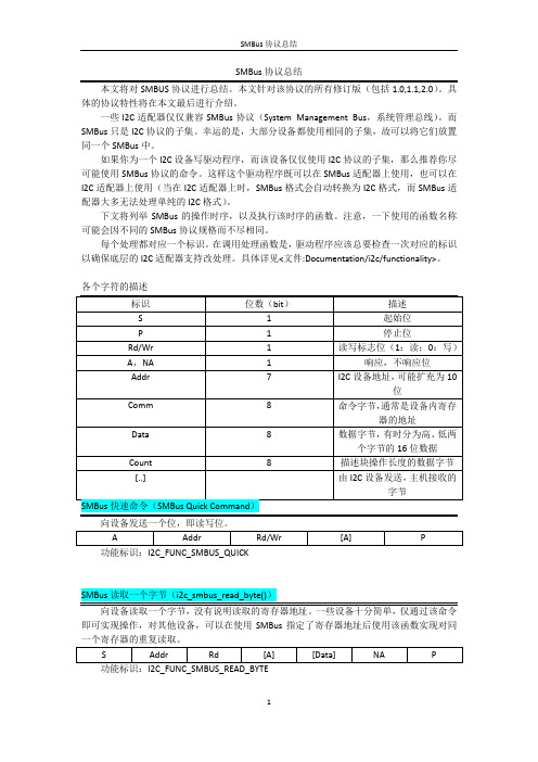
SMBus协议总结本文将对SMBUS协议进行总结。
本文针对该协议的所有修订版(包括1.0,1.1,2.0)。
具体的协议特性将在本文最后进行介绍。
一些I2C适配器仅仅兼容SMBus协议(System Management Bus,系统管理总线)。
而SMBus只是I2C协议的子集。
幸运的是,大部分设备都使用相同的子集,故可以将它们放置同一个SMBus中。
如果你为一个I2C设备写驱动程序,而该设备仅仅使用I2C协议的子集,那么推荐你尽可能使用SMBus协议的命令。
这样这个驱动程序既可以在SMBus适配器上使用,也可以在I2C适配器上使用(当在I2C适配器上时,SMBus格式会自动转换为I2C格式,而SMBus适配器大多无法处理单纯的I2C格式)。
下文将列举SMBus的操作时序,以及执行该时序的函数。
注意,一下使用的函数名称可能会因不同的SMBus协议规格而不尽相同。
每个处理都对应一个标识。
在调用处理函数是,驱动程序应该总要检查一次对应的标识以确保底层的I2C适配器支持改处理。
具体详见<文件:Documentation/i2c/functionality>。
各个字符的描述功能标识:I2C_FUNC_SMBUS_QUICK即可实现操作,对其他设备,可以在使用SMBus指定了寄存器地址后使用该函数实现对同一个寄存器的重复读取。
功能标识:I2C_FUNC_SMBUS_READ_BYTE功能标识:I2C_FUNC_SMBUS_READ_BYTE_DATA注意:还有一个读取字寄存器的函数i2c_smbus_read_word_swapped,使用于当寄存器两个字节排列方式不同时的情况。
虽然与SMBus不兼容,但使用得十分普遍。
功能标识:I2C_FUNC_SMBUS_WRITE_WORD_DATA注意:还有一个写字寄存器的函数i2c_smbus_write_word_swapped,使用于当寄存器两个字节排列方式不同时的情况。
Futaba T7PX T7XC 无线遥控器软件更新指南说明书

1M23Z05402T7PX/T7XC Software Update MethodWhenever improvements and new functions are available, the software of your T7PX/T7XC radio transmitter can be updated easily online free of charge. The updated software file will be shown on our website. Y ou can download it and make a copy on your microSD card. Below is the procedure for the software update.Procedure for the software updateCaution: Before you update the software, the battery that is connected to the T7PX/T7XC should be fully charged.Note: During the software update, the model data that is stored in the T7PX/T7XC should be kept without any change. (NOT erased and NOT changed.) However, for your safety, making a backup of your model data before the software update is highly recommended.1. Download the zip file of the update data from our website.2. Extract the zip file on your computer.3. The "FUTABA" folde r will be cre ate d on your computer.4. Copy the "FUT ABA" folder onto your microSD card.7. W h e n t h e s o f t wa r e u p d a t e i s c o m p l e t e d , "Completed" message is shown on the LCD display of your T7PX/T7XC. (See attached picture.)Tap the [Reset] button for "min./max." to re se t the maximumvalue indicate d by the whitepointe r on the me te r on thehome scre e n. At the same time,the "Min" and "Max." displays one ach te le me try se tting screare reset.A menu for home screen setting has been added. The display method of the meter displayed on the home screen and the display content have been changed. The steering and throttle operation can also be dis-played on the meter.n display toSelect [Instrument panel] in the home screen display settings. T ap the meter to be set on the home screen to select it. Use the following procedure to select the data to be displayed.Other-Added support to change SR mode of HPS-CT700.The condition function has been enhanced.*Up to 4 conditions can be used.*It is possible to name the condition.*Switching or condition can be switched by switch or trim / dial.3 T ap the [Condition] button to change the number of available conditions.A list of condition numbers is displayed in the "Condition name " group box. Up to 4 conditions can be used.This function allows you to assign a fifte e n characte r name to econdition.1 From the "Condition Name " list, tap the condition button whose nameyou want to change.2 Since the condition name setting screen is displayed, edit the name.3 T ap the title button [Condition name] to return to the condition screen.Condition nameThis function copies condition data to other conditions.1 T ap the [copy condition] button. The condition copy screen will be displayed.2 T ap the “Copy from” [Condition name], select the sondition list so it will tap. The source condition is selected and the list isclosed. In the same way, use the "Copy to" condition button to select the copy destination condition.Condition copy3 T ap the [Copy], The confirmation message “Are you sure” appears. T o execute copy, tap [Y es] and to cancel copy, select [No].When the copy destination condition name becomes the same name as the copy source, copying is complete.This function sets the switch to change the condition. There are two kinds of change methods as follows.- With one switch, change the Condition 1 and Condition 2.- Assign a condition to each switch, and operate the switch to change the condition.1 T ap the [Switch select] button to display a "Switch select " screen. (The "Switch select " screen can also be displayed fromthe "Linkage menu " or the "User menu ".)2 T ap the switch you want to use to display the function selection screen. By selecting [Condition 12] from the function list,you can change Condition 1 and Condition 2 by operating the switch. If you select [Condition 1] to [Condition 4] for each switch, you can change to the condition assigned by each switch operation.This function can change the condition by trim or dial. By operating T rim or Dial, you can change the condition as Conditionplayed from the "Linkage menu " or the "User menu ".)2 T ap the trim or dial you want to use to display the function selection screen. Since the function selection screen is dis-played, select [Condition] from the function list.Condition change switch settingCondition change trim / dial settingIt corresponds to the Kyosho Mini-Z EVO dedicated receiver RA-42. For futher instruction, Please also read the instruc-2 T ouch [Link] on the transmitter T7PX / T7XC screen, you will hear a chime sound and T7PX / T7XC will enter the link modefor 20 seconds.The following servos support SR mode setting.S3470SV / S9370SV / S9470SV / S9570SV / S9571SV / S9670SV * Only "SR type 1" can be selected for SR type.Additional function / MC (ESC) Link (MC970CR)When the trim or the dial is operated, the value of the function is displayed for a few seconds at the top of the screen.The MC970CR has been added to the "MC (ESC) link " function of Futaba ESC parameter change. *MC970CR is available only in the Japanese market. (As of Sep 2018)Example:The trim/dial is assigned to the gyro mixing function.For ESC in the past, ple asechoose Other.*Improvement in SR mode setting*Even if a servo that is not compatible with SR mode is connected to a T7PX/T7XC with softwareV2.0 to V2.2, the transmitter can switch the servo to SR mode, but the incompatible servo will not work and the servo program is damaged when you forcibly switch the servo to SR mode. Thus, the servo does not work. So, please never switch when you connect an incompatible servo to SR mode.The software has been improved so that a transmitter prohibits you from switching an incompatible servo to SRmode.Added support to change SR mode of HPS-CB700.When connecting a servo that is not com-patible with SR mode, a message "Unsup-ported" is displayed on the screen, but you can operate the SR mode select button.Please never select the SR mode setting when you see "Unsupported " on the display.When connecting a servo that is not com-patible with SR mode, you cannot operate the SR mode switching button.Futaba S.BUS / S.BUS 2 The "S. BUS servo " function (Instruction manual page 135) that allows you to change the servo parameters can now be set up wirelessly by connecting to the receiver.* A receiver compatible with the wireless setting function is required. (As of April 2018, R334SBS / R334SBS-E is compatible with wireless setting. Please update the previous receiver to version 2.0 or later.)When the link is completed, power cycle the receiver.ou can check the software version on the receiver screen.configure the syste Please update the receiver to below version 2.0.Home button· Set for T -FHSS system· Link with link buttonReceiver software versionConnect the S. BUS / S. BUS 2 servo as shown in the figure and the receiver battery to the channel of the receiver.- ReferenceWhe ste e and 2nd channeOther changes and additions- Operation change in the "Acceleration " range (instruction manual page 60) within EPA setting range.- Added poll number setting and gear ratio setting on Telemetry Link setting screen of non-Futaba sensor (Castle TL 0).- Added support to change SR mode of BLS373SV.the DISP side. T urn on the battery switch of the receiver and confirm that the servos can operate.The S.BUS servo screen is displayed in the following way.Menu screenS.Bus servo1 Tap the Read] button. The notes on wireless setting are displayed. T ap the[Close] button.Once this screen is displayed, it will not be displayed again until you turn the power back on.2 T setting data from the servo.- Communication port :T7PX communication port (conventional wired setting). - Wireless 1 (Rx Ch1) :Receiver channel 1- Wireless 2 (Rx Ch2):Receiver channel 2-"Reading succeeded" is displayed on the screen and the servo’s ID cord and currently set con-tents are read.normally.Che ck the T7PX and se rvo conne ction to se rvo and re pe at [Read]. (Che ck re ce ive r powe supply etc.)Futaba has added a function to program your Futaba R334SBS / R334SBS-E receiver from the T7PX.To update the receiver, you need a PC that can be connected to the Internet, a mini driver (to push the switch of the receiver), a micro SD card (commercial product), and a cord for CGY750 / GY701 / GY520 (optional) or DSC cord (optional).Preparing for update- Download the zip file of the update data from our website or your local distributor’s website.- Extract the zip file on your computer. A folder named "FUT ABA" is created.- Insert the micro SD card that contains the "FUT ABA" folder into the T7PX (see page 31 of the manual).Connection between T7PX and receiverIt conne cts to CH1 of there ce ive r and the communi-cation port of the transmitter.Hold down the Link switch first, and turn ON the receiver.After the LED flashes red once, release the Link switch and then press it again.2T ap the "Update" button on the screen. The update will start. A progress barwill be displayed indicating the progress. The LED of the receiver turns green,and it blinks green for a moment every time it accepts data from the T7PX.- Do not turn off the power of T7PX while updating.3Whe n the update is comple te d, a me ssage is displaye d on the scre e n, andthe LED of the receiver stays flashing green. Please turn off the power of thereceiver.Please check the operation before running (cruising).In the unlikely event that the model data is damaged and the T7PX stops working properly, it is possible to initial-ize the current model data in the following way.Note:This operation completely initializes the model data. Please do not use it except when data is broken.will be initialized, please re-set the data and check the operation carefully before use. T ocancel the operation, touch [No]. The power is turned off without initializing the data.- After initialization, the current model data will be initialized, so please set the data again before using and con-firm the operation.4When finished, return to the System menu screen by pressing the HOME button.ErrorIf an error display appeared, reinstall the update from the beginning.- The receiver is not in the update wait state- The cable is disconnected.- The power has been turned off- The micro SD card is not inserted in the T7PX.- There is no data on micro SD card.。
SBUS协议及编解码

SBUS协议及编解码关于遥控器与无人机的通信协议也有很多种,常见的数据协议如下:1.pwm:需要在接收机上接上全部pwm输出通道,每一个通道就要接一组线,解析程序需要根据每一个通道的pwm高电平时长计算通道数值。
2.ppm:按固定周期发送所有通道pwm脉宽的数据格式,一组接线,一个周期内发送所有通道的pwm值,解析程序需要自行区分每一个通道的pwm时长。
3.sbus:每11个bit位表示一个通道数值的协议,串口通信,但是sbus的接收机通常是反向电平,连接到无人机时需要接电平反向器,大部分支持sbus的飞行控制板已经集成了反向器,直接将以旧换新机连接到飞行控制器即可。
4.xbus:常规通信协议,支持18个通道,数据包较大,串口通信有两种模式,可以在遥控器的配置选项中配置。
接收机无需做特殊配置。
SBUS本质是一种串口通信协议,采用100K的波特率,8位数据位,两位停止位,偶效验,即8E2的串口通信。
SBUS是一bai个接收机串行总线du输出,通过这根总线,可以获得遥控器上所有zhi通道的数据。
目前很多模型及无人机电子设备都支持SBUS总线的接入。
使用SBUS总线获取通道数据,效率高的,而且节省硬件资源,只需要一根线即可获取所有通道的数据。
SBUS总线使用的是TTL电平的反向电平,即标准TTL中的1取反为0,而0则取反为1,串口波特率为100000,数据位为8位,2个停止位,偶校验。
SBUS一帧数据的长度为25个字节,其中第'0'个字节为帧头:0x0f;第24个字节为帧尾:0x00;从第1个字节到第22个字节为1-16号比例通道的数据字节;第23字节中,第7位为数字开关通道17通道,第6位为数字开关通道18通道。
第5位为帧状态标志为(判断是否丢帧),用于控制接收机上的LED的状态,第4位为失控保护激活标志位,此位为1时,表示接收机进入失控保护状态。
值得注意的有三点:1.SBUS采用负逻辑,所以无论接收还是发送都要进行硬件取反(注意,一定要硬件取反),电路如下这是我在网上看资料时看到的电路,实际上我用的是7404电路2.SBUS有两种模式,a.高速模式:每4ms发送一次b.低速模式:每14ms发送一次就是说每间隔4或者14ms这个串口就发送25个字节的数据,这25个字节的数据最多可以包含16个信息3.100K的波特率不是标准波特率,一般串口工具都不能直接读取(所以不要直接用电脑调试,除非你的电脑写好了非标准串口),可以用单片机读取。
- 1、下载文档前请自行甄别文档内容的完整性,平台不提供额外的编辑、内容补充、找答案等附加服务。
- 2、"仅部分预览"的文档,不可在线预览部分如存在完整性等问题,可反馈申请退款(可完整预览的文档不适用该条件!)。
- 3、如文档侵犯您的权益,请联系客服反馈,我们会尽快为您处理(人工客服工作时间:9:00-18:30)。
航模遥控S-BUS协议解析
——写代码的Tobem
S-BUS的帧格式为每帧25个字节,除去起始字节(startbyte)、结束字节(endbyte)和校验标志(flags)后,中间的22个字节就是16个通道的数据了。
每个通道用11bit表示,范围是0-2047。
其中,data1为ch1的低8位,data2的低3位为ch1的高三位,data2的高5位是ch2的低5位,data3的低6位是ch2的高6位,以此类推。
实际中,只用到8个通道,因此,程序中只解析前面的8个通道。
因此,当接收到遥控数据并判断有效后(校验标志flags为0x00,即SBus_Buffer[22]==0X00),先把每一通道的值通过位的方式进行提取:
for(i=0;i<88;i++) //8个通道:8*11=88
{
if(Buff[Byte_in_Sbus]&(1<<Bit_in_SBus))
{
Channels[Channel_Count]|=1<<Bit_in_Channel; //按位方式进行通道数据提取}
Bit_in_SBus++;
Bit_in_Channel++;
if(Bit_in_SBus==8) //每取完8位,则字节数加1
{
Bit_in_SBus=0;
Byte_in_Sbus++;
}
if(Bit_in_Channel==11) //每取完11位,则通道数加1
{
Bit_in_Channel=0;
Channel_Count++;
}
}
其中,通道0对应横滚控制,通道1对应俯仰控制,通道2对应油门控制,通道3对应方向控制:
channel_roll.radio_in=Channels[0]; //横滚
channel_pitch.radio_in=Channels[1];//俯仰
channel_throttle.radio_in=Channels[2];//油门
channel_rudder.radio_in=Channels[3];//方向
通道4和通道5用于飞行模式的切换,由于其采用指拨开关,因此通过前后两次通道值的变化以及当前通道值所处区间来判断模式的改变:
if(fabs(Channels[4]-last_channel_4)>300) //条件成立,说明前后两次开关有改变
{
last_channel_4 = Channels[4]; //记录上一次的值
if(Channels[4]<400) //4通道用于控制模式切换:下;自动
{
control_mode = MANUAL;
}
else if(Channels[4]<1100) //中;增稳模式
{
control_mode = STABILIZE;
}
else if(Channels[4]<1750) //上;手动
{
control_mode =AUTO;
}
}
if(fabs(Channels[5]-last_channel_5)>300) //条件成立,说明前后两次开关有改变
{
last_channel_5 = Channels[5];
if(Channels[5]<400) //5通道用于飞行模式切换:下;返航
{
flight_mode = Loiter ;
}
else if(Channels[5]<1100) //中;航线
{
flight_mode = Navigation_Line;
}
else if(Channels[5]<1750) //上;盘旋
{
flight_mode = Rtl;
}
}
假如遥控器连接不正常(校验标志flags为0x0C,即SBus_Buffer[22]==0X0C),则按遥控归中处理:
if(SBus_Buffer[22]==0X0C) //遥控器连接不正常
{
channel_roll.radio_in=1024;
channel_pitch.radio_in=1024;
channel_throttle.radio_in=343;
channel_rudder.radio_in=1024;
}。
