SoC层次化测试方法
一种基于IEEE1149和IEEE1500标准的层次化SoC测试方案[发明专利]
![一种基于IEEE1149和IEEE1500标准的层次化SoC测试方案[发明专利]](https://img.taocdn.com/s3/m/1b765103ae45b307e87101f69e3143323968f511.png)
专利名称:一种基于IEEE1149和IEEE1500标准的层次化SoC 测试方案
专利类型:发明专利
发明人:梅张雄,程晟,邱芬
申请号:CN202110649053.6
申请日:20210610
公开号:CN113433448B
公开日:
20220503
专利内容由知识产权出版社提供
摘要:本发明公开了一种基于IEEE1149和IEEE1500标准的层次化SoC测试方案,涉及SoC芯片测试领域;其中,IEEE1500标准协议用于独立的进行SoC内部单个嵌入式内核测试,通过在嵌入式内核与系统之间定义内核测试接口来标准化IP内核测试结构,以便通过内核访问机制促进内核的测试复用;同时有效完成内核的测试和隔离,分区测试块之间的切换,达到完整测试SoC的目的;本发明通过改进IP内核集成的外围电路,实现层次化SoC中内核外核并行同步测试,最终达到减少测试时间的目的;可以为大型SoC产品提供灵活和高效率的设计方案。
申请人:北京联盛德微电子有限责任公司
地址:100037 北京市海淀区阜成路67号17层1802
国籍:CN
代理机构:北京中誉至诚知识产权代理事务所(普通合伙)
代理人:张平力
更多信息请下载全文后查看。
soc测试方法

soc测试方法SOC测试方法是一种用于评估软件系统安全性的方法。
它通过模拟真实攻击场景,测试系统的漏洞和弱点,以确保系统在面临各种威胁时能够保持稳定和安全。
在SOC测试中,首先需要确定测试的目标和范围。
这包括确定测试的系统组件和功能,以及测试的时间和资源限制。
然后,测试团队将根据系统的设计和实现文档,分析系统的安全需求和威胁模型,并制定测试策略和计划。
在测试策略中,测试团队将选择合适的测试方法和技术,以评估系统的安全性。
常用的SOC测试方法包括黑盒测试、白盒测试和灰盒测试。
黑盒测试是在没有系统内部信息的情况下进行的,模拟真实攻击者的行为,测试系统的安全性。
白盒测试则是基于系统的内部信息进行的,测试系统的实现是否符合安全标准和最佳实践。
灰盒测试则结合了黑盒测试和白盒测试的特点,既考虑系统的外部行为,又考虑系统的内部结构和实现。
在具体的SOC测试过程中,测试团队将根据测试策略和计划,执行一系列的测试用例和攻击场景。
测试用例是一组输入和预期输出的组合,用于评估系统的功能和安全性。
攻击场景则是模拟真实攻击者的行为,测试系统的弱点和漏洞。
在测试过程中,测试团队将记录和分析测试结果,并根据结果调整测试策略和计划。
测试结果包括系统的漏洞和弱点,以及相应的修复建议。
测试团队还将评估系统的安全性能和可靠性,以确保系统在面临威胁时能够保持稳定和安全。
SOC测试方法是一种评估软件系统安全性的方法,通过模拟真实攻击场景,测试系统的漏洞和弱点。
它是确保系统安全性的重要手段,可以帮助组织保护其信息资产和业务运行的安全。
通过合理的测试策略和计划,以及准确的评估和分析,SOC测试可以提高系统的安全性,并帮助组织及时发现和修复系统中的安全问题。
基于RVM的层次化SoC芯片平台的设计及应用

基于RVM的层次化SoC芯片平台的设计及应用随着设计日趋复杂,验证成为SoC设计过程中最关键的环节。
本文介绍了Synopsys的RVM验证办法学,采纳Vera硬件验证工具以及OpenVera 验证语言建立目标模型环境,自动生成激励,完成自核对测试、笼罩率分析等工作。
通过建立层次化的可重用性验证平台,大大提高了验证工程师的工作效率。
文中以一个SIMC功能模块的验证为例,具体介绍了RVM验证办法学在SoC芯片验证中的应用。
功能验证一个设计被综合前,首先要对RTL描述举行规律功能验证,以确保模块或芯片的功能正确性。
通常,RTL级的功能验证主要采纳自底向上的验证策略,可分为模块级验证和系统级验证两个阶段。
传统验证办法大多是在信号级的接口上挺直与待验证设计(DUT)通信,即用激励挺直驱动DUT的引脚,通过检查接口信号的值和变幻来达到验证设计功能的目的。
这种办法的抽象层次较低,验证平台的开发与DUT 的接口协议紧密相关,使得验证平台的重用性较差。
假如要做到一个验证平台可以验证多个不同的DUT,必需将验证平台的抽象层次提高到事务级,而且应当构建层次化的结构,层与层之间具有一定的自立性,转变底层并不会影响上层。
基于事务的验证所谓事务(Transaction)是指设计对象与事务处理器(Transactor)之间通过接口所做的一次数据传输。
从硬件的角度来看,事务可看成作用在一个特定接口上的一组信号的集合单元。
事务具有3个要素:起始时光、终止时光,以及全部与这个事务相关的信息。
基于事务的验证工具让用户除了可以在信号/引脚级上举行验证,还可以在事务级上举行验证,从而提高了设计生产率。
基于事务验证环境的基本要素DUT:待验证设计对象的RTL描述或门级描述。
第1页共7页。
SOC芯片测试要求
SOC芯片测试要求1.功能测试:功能测试是验证芯片是否按照设计规格正确工作的关键。
测试需要覆盖所有的功能模块,并验证其是否按照设计要求正确操作。
这包括指令集的正确执行、数据通路的正确连接、输入和输出接口的正确性等。
功能测试需要覆盖正常操作和异常操作,以确保芯片在各种情况下都能正确工作。
2.性能测试:性能测试是验证芯片的性能参数是否满足设计要求的重要环节。
性能测试需要测试芯片的时钟频率、指令执行速度、存储器访问延迟、处理器吞吐量等性能指标。
性能测试需要考虑芯片的工作环境和应用场景,确保芯片能够在各种情况下都能够达到性能要求。
3.电气测试:电气测试是验证芯片的电性能是否满足设计要求的关键步骤。
电气测试需要对芯片进行电压测试、功耗测试、时钟信号测试等。
电气测试需要保证芯片在各种电气条件下都能够正常工作,避免电源噪声、电磁干扰等对芯片性能的影响。
4.容错测试:容错测试是验证芯片在面对异常情况时是否能正确处理的重要环节。
容错测试需要覆盖各种可能的异常情况,包括软件错误、硬件错误、通信错误等。
容错测试需要验证芯片在异常情况下是否能正确识别和处理错误,以确保芯片的可靠性和稳定性。
5.温度测试:温度测试是验证芯片在高温或低温环境下是否能正常工作的重要环节。
温度测试需要测试芯片在不同温度下的性能和可靠性,以确保芯片能在各种环境条件下都能正常工作。
温度测试需要考虑芯片的散热设计和温度控制,以避免过高或过低温度对芯片的损害。
6.可靠性测试:可靠性测试是验证芯片在长时间工作条件下是否能保持稳定和可靠的关键步骤。
可靠性测试需要对芯片进行加速寿命测试、高温老化测试、电磁干扰测试等,以验证芯片的可靠性和耐久性。
可靠性测试需要模拟芯片在实际应用中的工作条件,并测试其在不同工作条件下的稳定性和可靠性。
综上所述,SOC芯片测试要求包括功能测试、性能测试、电气测试、容错测试、温度测试和可靠性测试等。
通过全面、系统地测试和验证,确保芯片具有稳定、高效、可靠的性能,满足用户的需求。
SoC系统测试与分析
SoC系统验证方法
• 在实际中对SoC进行验证时,由于它是由多个功 能块组成,可以将SoC的整个系统级测试平台运 用于系统芯片的每一个子模块(功能块),实现 对每个功能块的细节进行验证。
SoC系统验证方法
• 对SoC功能块的细节进行验证时,可以采用如下 多种方法:硬件建模、接口验证、软/硬件协同验 证、随机测试、基于应用程序的验证、门成测试矢量;数据信 号发生器根据计算机的要求产生测试波形,并加载 到被测电路上;逻辑分析仪采集被测电路的响应信 号并进行一定的分析,然后将结果送到计算机中进 行处理。
基于神经网络的电路测试生成 方法
• 人工神经网络(ANN)由于其优良的特性,能较 好的处理目前串行计算机难于解决的NP完全问题
(如Hopfield神经网络用于TSP问题的求解)。 • 根据组合电路测试生成的特点,选用Hopfield神
经网络作为电路建模的基础,用神经网络的能量 函数来表征电路的逻辑特性。
二元判定图BDD
• 二元判定图(BDD)就是一种较有效的方法,它将 布尔函数的功能用有向无环图来表示,图中从根 节点到叶节点的路径对应了布尔函数值为1的一个 输入矢量。
目的是检查行为设计是否满足功能需求。 性能验证:
目的是检查所选出的架构是在满足功能需求之 外是否能满足性能需求。
SoC系统验证方法
在整个验证过程中,都将使用测试平台来检验设 计对象的功能,系统级测试平台是整个验证过 程的一个关键。
SoC系统验证方法
从系统规约中提取出一项 功能要求,并定义出检验 其功能的具体测试,重复 进行,直至为每一项功能 都建立了测试。
SoC系统验证方法
在系统芯片的设计过程中,系统规约确定之后 进行系统级设计。首先对系统行为进行建模,根 据功能规范要求对行为模型进行验证;然后将行 为模型映射到由芯核和功能块组成的架构之上。 目的就是去验证该架构的功能和性能。
soc测定方法
soc测定方法下载温馨提示:该文档是我店铺精心编制而成,希望大家下载以后,能够帮助大家解决实际的问题。
文档下载后可定制随意修改,请根据实际需要进行相应的调整和使用,谢谢!并且,本店铺为大家提供各种各样类型的实用资料,如教育随笔、日记赏析、句子摘抄、古诗大全、经典美文、话题作文、工作总结、词语解析、文案摘录、其他资料等等,如想了解不同资料格式和写法,敬请关注!Download tips: This document is carefully compiled by the editor. I hope that after you download them, they can help yousolve practical problems. The document can be customized and modified after downloading, please adjust and use it according to actual needs, thank you!In addition, our shop provides you with various types of practical materials, such as educational essays, diary appreciation, sentence excerpts, ancient poems, classic articles, topic composition, work summary, word parsing, copy excerpts,other materials and so on, want to know different data formats and writing methods, please pay attention!社会认知能力(SOC)是指个体在社会交往中的认知能力,包括理解他人的情绪、思想和意图,以及适当地调整自己的行为以应对不同的社会情境。
soc测试方法
soc测试方法SOC (Security Operations Center) testing is an essential part of cybersecurity. It involves evaluating the effectiveness of an organization's SOC in detecting, analyzing, and responding to security incidents. Here are some commonly used methods for SOC testing:1. Penetration Testing: This involves simulating real-world attacks to identify vulnerabilities in the SOC infrastructure. It helps assess the ability of the SOC team to detect and respond to different types of attacks.2. Red Team Testing: Red team testing goes beyond penetration testing by conducting targeted attacks on the organization's network and systems. It helps evaluate the SOC's ability to detect and respond to sophisticated and advanced threats.3. Blue Team Exercises: Blue team exercises involve creating simulated security incidents and observing how the SOC team responds to them. It helps identify any gaps in the SOC's monitoring, detection, and response processes.4. Scenario-Based Testing: Scenario-based testing involvessimulating specific security incidents, such as a data breach or ransomware attack, and assessing the SOC's response. It helps validate the effectiveness of the SOC's processes, tools, and personnel.5. Log Analysis: Analyzing logs generated by the SOC's monitoring tools can provide insights into the SOC's ability to detect and respond to security incidents. It helps identify any anomalies or patterns that may indicate potential threats.6. Tabletop Exercises: Tabletop exercises involve conducting simulated security incident response drills with SOC team members. It helps enhance communication, coordination, and decision-making within the SOC team.7. Threat Hunting: Threat hunting involves proactively searching for potential security threats and indicators of compromise within an organization's network and systems. It helps identify any blind spots or weaknesses in the SOC's detection capabilities.8. Metrics and Reporting: Regularly monitoring and analyzing key performance indicators (KPIs) and metrics canprovide insights into the effectiveness of the SOC. It helps identify areas for improvement and measure the SOC's overall performance.It's important to note that SOC testing should be conducted in a controlled and planned manner to avoid any disruption to the organization's operations and ensure the confidentiality, integrity, and availability of its systems and data.。
SOC芯片测试要求
输出频率范围
Embedded Memory测试
自带memory bist
由测试机生成
标准测试向量
Flash
SRAM
E2
Embedded CPU测试
自带测试方案
由测试机生成
标准测试向量
ARM7
ARM9
8051
Scan测试
number of scan chain
4
√
max depth of scan chain
SOC芯片测试要求(请于需AM消费电子
逻辑管脚数
电源电压(内核/IO)
1.8/3.3
设计工作频率(内核/IO)
封装形式
WAFER
测试项目
描述
打勾
接触
验证程序(DC方法)
(便于Debug,但费时)
量产程序(向量方法)
(不便Debug,但省时)
模块化功能测试
PLL测试
STIL 1.0格式文件,不清楚深度
功能测试
Function测试
number of test pattern
单时钟域
125MHz以下
125~250MHz
250MHz以上
双时钟域
分/倍频关系
测试项目
设计参数
打勾
静态参数测试
输入漏电流(IIH/IIL)
输出漏电流(IOZH/IOZL)
输入电压(VIH/VIL)
输出电压(VOH/VOL)
动态功耗测试(Idd)
静态功耗测试(Idds)
平均功耗测试(Idda)
时序测试
TIMING 1
TIMING 2
TIMING 3
TIMING 4
soc验证方法

soc验证方法1. 什么是SoC验证方法SoC验证方法指的是系统级芯片(System-on-Chip,简称SoC)的验证过程中所采用的方法和技术。
SoC是由多个IP核组成的复杂集成电路系统,包括处理器核心、内存、外设接口等。
SoC验证方法的目标是确保设计在实际硬件上的正确性和可靠性。
SoC验证方法可以帮助开发者识别硬件设计中的错误,验证系统在各种情况下的功能和性能,并确保各个IP核的协同工作。
它是SoC设计流程中非常重要的一环,因为SoC设计周期长、成本高,一旦出现问题,则需要付出更大的代价来修复。
2. SoC验证方法的重要性SoC验证方法的主要目标是确保系统在不同工作场景下的正确性和稳定性。
由于SoC系统的复杂性,不同IP核之间的交互可能会引发各种潜在问题,例如时序问题、通信信道冲突等。
SoC验证方法的重要性体现在以下几个方面:SoC验证方法可以帮助开发者找出设计中的错误和缺陷。
通过模拟、仿真和验证测试等手段,可以快速发现设计中存在的问题,并及时进行修复,以提高整体的设计质量。
SoC验证方法可以确保系统在各种使用场景下的正确性。
通过在各种环境和工作负载下的验证,可以验证系统的稳定性和性能,确保系统在实际使用中能够正常工作。
SoC验证方法还可以提高开发效率。
通过自动化验证流程,可以减少手动验证的工作量,提高验证的效率和准确性,并且能够在验证过程中捕捉更多的错误。
总结而言,SoC验证方法的重要性在于它可以确保整个SoC系统的正确性和稳定性,提高开发效率,减少调试和修复的工作量。
3. SoC验证方法的分类SoC验证方法可以分为传统的验证方法和基于硬件加速器的验证方法两大类。
传统的SoC验证方法主要包括模拟器验证、仿真验证和验证测试等。
其中,模拟器验证是利用硬件描述语言(HDL)和仿真软件对SoC系统进行功能验证,包括验证各个IP核的工作正常性以及整个系统的交互性。
仿真验证是通过模拟软件来验证系统的时序和性能,以确保各个时钟域和信号传输路径的正确性和同步性。
SoC可测性设计与测试概述知识讲解

S o C可测性设计与测试概述SoC可测性设计与测试概述Summarization for DFT and test of SoCBy MYJY2012-4 in NJ摘要:本文简述了SoC的可测性设计的意义,以及SoC测试相关知识,并介绍了一些SoC测试数据压缩的方法,旨在对SoC的测试有更好更全面的了解。
关键词:SoC,可测性设计,测试,压缩Abstract:This paper present the significance of DFT and knowledge related to SoC test. It also introduce several data compression techniques. As a result, we can learn more about SoC test.Key words:SoC,DFT,test,compression1 引言随着社会与科技的不断发展,VLSI(Very Large Scale Integration)复杂程度不断提高尺寸也日益缩小,VLSI的设计与测试也愈发受到关注。
SoC(System on chip)作为集成电路发展的必然趋势,确保其有效性也作为VLSI发展的一个愈发重要的课题,所以SoC测试在产品的整个开发过程中也占据了越来越重要的地位。
2 Soc定义SoC的定义多种多样,通常具有采用深亚微米DSM技术、IP核复用、软硬件协同设计这三个特征。
Soc结构应用越来越广泛,其基于核的设计复用技术大大提高了复杂的电子系统的设计效率,所以SoC 也是集成电路未来发展的趋势。
3 SoC可测性设计3.1 SoC可测性设计的必要性相较于传统的IC设计,SoC具有多个不同的的特点:(1)SoC由数量级高达百万甚至更多的元器件组成,电路结构复杂,设计起点比普通ASIC高,需采用数模混合方法验证。
(2)SoC一般使用深亚微米甚至超深亚微米(VDSM,<0.25μm)技术进行生产,延迟成为必须考虑的因素,加上线间和层间由于间隔很小而导致耦合作用增强等各方面因素,设计验证变的相对困难。
soc测试方法 -回复

soc测试方法-回复对于社会科学研究,测试方法是非常重要的一环。
通过科学的测试方法,可以验证和证伪社会科学理论,揭示现象背后的规律,为社会问题的解决提供依据。
本文将以“soc测试方法”为主题,一步一步回答。
第一步:确定研究目标在进行soc测试方法研究之前,需要先明确研究目标。
也就是要确定我们想要研究的问题是什么,具体的研究目标是什么。
比如,我们想要研究某种社会现象的成因或影响因素,或者想要验证某个社会科学理论的正确性等。
明确研究目标有助于我们选择相应的测试方法。
第二步:选择适当的测试方法在社会科学研究中,有多种测试方法可供选择。
根据研究目标和研究问题的具体情况,选择适当的测试方法非常重要。
以下介绍几种常见的soc测试方法。
1. 实证研究方法:实证研究方法是社会科学研究中最常用的方法之一。
它通过收集和分析大量的实际数据,根据统计学或数理模型等分析方法,揭示出数据背后的规律和关系。
实证研究方法更注重事实和数据,以验证或证伪研究假设或理论。
2. 实地观察法:实地观察法是在研究对象所在的现场进行直接观察的方法。
通过亲自到现场观察、记录和分析,可以获取更真实、全面的数据和信息。
实地观察法特别适合于探索性研究和对极具复杂性或特殊性的社会问题进行深入研究。
3. 问卷调查法:问卷调查法是常用的soc测试方法之一。
通过设计问卷,以书面或在线形式向被调查者提问,获取他们的意见、观点和行为等信息。
问卷调查法可快速收集大量数据,适用于大样本数量的研究,但要注意问卷设计和抽样方法的合理性。
4. 访谈法:访谈法是通过直接与被调查者进行面对面的交流,深入了解他们的观点、体验和行为等。
访谈法可以获得丰富的、深入的主观信息,有助于理解和分析被调查者的内在动机和行为背后的原因。
第三步:设计实施测试在选择适当的测试方法后,需要进行具体的测试设计和实施。
这包括确定研究对象、制定测试方案、选择合适的指标和数据收集方法、设计问卷或访谈提纲、确定样本数量和抽样方法等。
soc面试基础知识

soc面试基础知识SOC(System on Chip)是指在一个芯片上集成了处理器核心、内存、外设接口等多个功能模块的集成电路。
SOC技术的发展使得计算机系统可以更加紧凑和高效,广泛应用于各种设备和领域。
在SOC面试中,基础知识是面试官们常常会考察的内容之一。
下面就来介绍一些SOC面试的基础知识。
一、SOC的定义和特点SOC是一种集成电路技术,将多个功能模块集成到一个芯片上。
这些功能模块可以包括处理器核心、内存、外设接口等,可以根据需要进行定制和设计。
SOC的特点是集成度高、功耗低、性能高、体积小等。
二、SOC的应用领域SOC技术已经广泛应用于各个领域,包括消费电子、通信、汽车、工业控制等。
在消费电子领域,SOC被广泛应用于智能手机、平板电脑、智能电视等设备中。
在通信领域,SOC被用于移动通信设备、网络设备等。
在汽车领域,SOC被用于汽车电子系统、车载娱乐系统等。
在工业控制领域,SOC被用于工业自动化设备、机器人等。
三、SOC的体系结构和设计方法SOC的体系结构可以根据应用需求来设计,可以采用单核心、多核心、异构核心等不同的结构。
在设计SOC时,需要考虑功耗、性能、可靠性等因素。
SOC的设计方法有自顶向下和自底向上两种。
自顶向下的设计方法是从系统级需求出发,逐步细化到电路级。
自底向上的设计方法是从电路级出发,逐步组合成系统级。
四、SOC的测试和验证SOC的测试和验证是确保SOC功能正常的重要环节。
SOC的测试可以分为结构测试、功能测试和系统测试等多个层次。
结构测试主要用于检测电路的连通性和正确性。
功能测试主要用于检测SOC的各个功能模块是否正常工作。
系统测试主要用于检测整个SOC系统是否满足设计需求。
SOC的验证可以采用仿真验证、硬件验证和软件验证等方法。
五、SOC的性能和功耗优化在SOC设计过程中,性能和功耗是两个重要的优化指标。
性能优化可以通过优化算法、增加处理器核心数量、增加缓存等方法来实现。
SoC 测试概念

SoC测试的概念及实例详解本文主要介绍了一个具有可测性设计和可制造性设计的新型单片系统,该系统由硬盘控制器(HDC)、16位微控制器、微控制器使用的程序和数据SRAM以及用8M位DRAM实现的片上缓存组成,再加上时钟综合PLL、带外部旁路晶体管的稳压器使用的片上控制电路组成一个完整的系统。
该器件采用的是0.18μm的铜工艺,与前几代技术相比增加了性能、降低了功耗。
另外,DRAM也采用了深亚微米技术,因此在一个器件中可以包含进一个完整的系统缓存(1MB)以及自动刷新逻辑,而且使用的硅片面积还比以前小。
本文还讨论了DFT和DFM所采取的对策,包括为了实现更快的良品率学习曲线而采用面向分析工具的设计、为减少测试成本而采取的并行测试方法。
DFT和分析存取是通过IEEE 1149.1的JTAG控制器实现的。
除了专门的存储器测试和ATPG扫描外,JTAG控制器还能为组成完整SoC的各个不同单元提供各种测试模式配置。
所采用的设计对策决不是只有唯一一种可能性。
由于存储器在器件中占了45%的硅片面积和86%的晶体管数量,因此需要对存储器加以重点关注。
存储器测试是重点考虑和努力开发的对象。
图1:扫描模式配置。
SRAM有两种测试方法,具体取决于SRAM在系统中的用途:CPU存储器(代码和数据)是通过微控制器进行测试的,需要特殊硬件配置和测试模式的支持;与HDC相关的SRAM采用存储器BIST电路进行测试。
DRAM则通过BI ST控制器进行测试,而DRAM BIST自身利用扫描和ATPG进行测试。
大多数数字逻辑是完全综合过的,而所有数字逻辑都要经过ATPG扫描测试。
另外,象PLL和稳压器控制等模拟电路则采用特殊编制的程序在特殊测试模式下进行测试。
本文首先介绍系统级芯片本身,包括SRAM和嵌入式DRAM,然后简要讨论用于指导DFT和DFM开发工作的分析与生产测试对象,最后阐述了SoC中采取的分析和生产测试对策。
系统级芯片概要为了有助于了解生产测试与分析所采取的对策,首先让我们看一下SoC 的一些细节,当然本文提到的所有性能都需要进行测试。
soc验证流程和方法

soc验证流程和方法SOC verification is a critical process in the development of modern integrated circuits, helping to ensure the functionality, performance, and reliability of complex System-on-Chip designs. SOC验证是现代集成电路发展过程中的关键步骤,有助于确保复杂片上系统设计的功能性,性能和可靠性。
One common method for SOC verification is simulation, where the behavior of the design is tested using software models before the physical chip is manufactured. Simulation allows engineers to identify and correct errors in the design early in the development process, reducing the chances of expensive rework later on. 一种常见的SOC验证方法是模拟,即在制造物理芯片之前,使用软件模型测试设计的行为。
模拟允许工程师在开发过程的早期识别和纠正设计中的错误,减少贵重的重做机会。
Another approach to SOC verification is formal verification, which involves mathematically proving that the design meets its specifications. Formal verification is particularly useful for verifying complex algorithms or properties that are difficult to test withsimulation alone. 另一种SOC验证的方法是形式验证,涉及数学上证明设计符合其规格。
SOC测量方法范文

SOC测量方法范文SOC (State of Charge)是指电池的充电状态。
对于电动汽车和可再充电储能系统而言,准确测量SOC是非常重要的,因为它对电池的性能和使用寿命有着直接影响。
目前,有许多方法可以测量SOC,下面将介绍常用的几种方法。
1. 电流积分法(Coulomb计数法):这是最简单、最直接的方法之一、该方法通过积分测量进入和离开电池的电流来计算SOC。
积分电流的误差会随着时间的增加而累积,因此需要周期性地进行校准。
该方法的优点是简单、低成本,但存在着容量衰减、自放电和电流测量精确度等问题。
2. 开路电压法(Open Circuit Voltage, OCV):这种方法是通过测量电池在静置状态下的开路电压来估计SOC。
在充电和放电过程中,电池的开路电压与SOC之间存在一定的相关性。
对于新电池,开路电压与SOC之间的关系相对稳定,但随着使用寿命的增加,该关系会发生变化。
因此,该方法的准确性会随着电池老化而降低。
3. 过载加电法(Polarization-Based Methods):这种方法是通过测量电池过载状态下的电压响应来估计SOC。
具体而言,当电池在过载状态下放电时,会产生极化现象,导致电池电压下降;而在充电时,电池电压会上升。
根据电池电压与SOC之间的相关性,可以通过测量电压变化来计算SOC。
然而,该方法对电池的放电和充电特性以及环境的温度等因素非常敏感。
4. Kalman滤波法:Kalman滤波器是一种用于估计状态变量的自适应滤波器,可以结合多个输入数据进行状态估计。
对于SOC的估计,可以通过Kalman滤波器综合考虑电流测量、电压测量和电池模型等输入数据。
这种方法通过对电流和电压测量值进行动态建模和估计,可以更准确地估计SOC。
然而,该方法需要根据电池的特性和环境参数进行参数的调整和校准。
除了以上几种方法外,还有很多其他的SOC测量方法,如电化学阻抗谱法、傅立叶变换红外光谱法、放射性同位素法等。
SOC基于RVM层次化验证模型中的信道应用
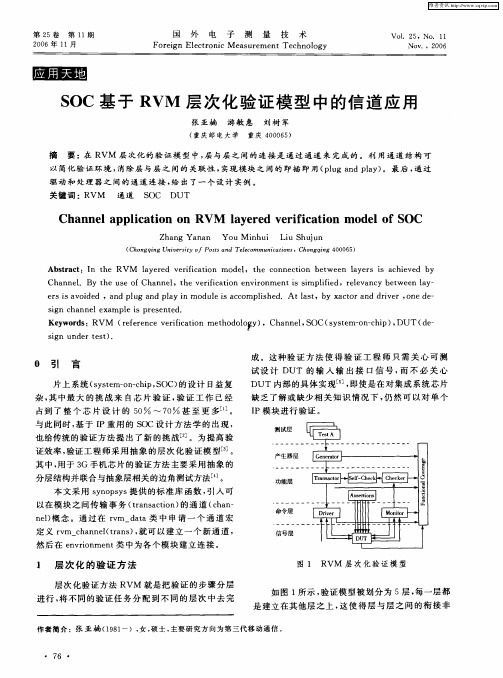
也 给传统 的验证 方法 提 出 了新 的挑 战【 。为 提 高验 2 ] 证 效率 , 验证工 程 师采 用 抽象 的层次 化 验证 模 型[ 。 3 ]
产 生 器 层
其中 , 用于 3 G手 机芯 片的验 证方 法 主要采 用抽 象 的
分层结构并联合 与抽象层相 关的边角测 试方法l 。 - 4 J 本文 采用 s n p y 提 供 的标准 库 函数 , 入可 y oss 引 以在 模块 之 间传输 事 务 (rna t n 的通 道 ( h n ta sci ) o ca — n 1概 念 。通过 在 rm— aa类 中 申请 一 个 通 道 宏 e) v dt
驱 动 和 处 理 器 之 间 的 通 道 连 接 , 出 了一 个 设 计 实例 。 给
关键词 : RVM 通 道 S C D O UT
Cha ne p lc to n RVM a e e e ii a i n m o e f S n la p i a i n o l y r d v r f c to d lo OC
sgn c n le a pl s pr s n e i ha ne x m e i e e t d.
Ke wo d :RV M ( e ee c e i c to t o oo y ,Ch n e , OC( y t m— n c i ) DUT ( e y rs r fr n e v rf a in me h d l g ) i a n lS s se o —h p , d—
维普资讯
第2 5卷
第 1 期 1
国 外 电
子
测 量
技
术
Vo1 2 . 5,N o 1 . 1 NOV ., 2 6 00
20 0 6年 I 1月
基于UML的SoC层次化设计模型研究
基于UML的SoC层次化设计模型研究
马钊坤;韩国栋
【期刊名称】《计算机工程与设计》
【年(卷),期】2010(031)024
【摘要】为了进一步提高基于统一建模语言(unified modeling language,UML)的系统集成芯片(system on a chip,SoC)设计技术的开发效率,提出一种层次化设计模型.该模型在软硬件协同设计之前先建立与系统实现方式无关的逻辑功能模型;然后使用设计空问搜索技术决策系统最佳实现方案,为系统设计者提供系统实现方式选择平台.同时通过定义4个设计模型概念层及相应的层间接口建立层次化的设计模型,方便设计模型数据在开发组内交互,减少重复工作.最后介绍了层次化设计模型在多种开发模型及设计模式中的应用,表明了层次化模型的灵活性.
【总页数】4页(P5265-5268)
【作者】马钊坤;韩国栋
【作者单位】国家数字交换系统工程技术研究中心,河南,郑州,450002;国家数字交换系统工程技术研究中心,河南,郑州,450002
【正文语种】中文
【中图分类】TP391.72
【相关文献】
1.基于UML的需求分析模型及设计模型度量 [J], 姚珺
2.基于平台和层次化功耗管理的蓝牙SoC研究与设计 [J], 李振荣;庄奕琪;牛玉峰
3.基于规则的UML设计模型的一致性检验 [J], 刘晓建;李战怀
4.基于UML的面向对象的图形用户界面设计模型 [J], 孙晓平;郭腾冲;魏明珠;涂序彦
5.基于UML的SoC建模设计方法研究 [J], 张海涛;龚龙庆
因版权原因,仅展示原文概要,查看原文内容请购买。
- 1、下载文档前请自行甄别文档内容的完整性,平台不提供额外的编辑、内容补充、找答案等附加服务。
- 2、"仅部分预览"的文档,不可在线预览部分如存在完整性等问题,可反馈申请退款(可完整预览的文档不适用该条件!)。
- 3、如文档侵犯您的权益,请联系客服反馈,我们会尽快为您处理(人工客服工作时间:9:00-18:30)。
D E S I G N -T O -S I L I C O NW H I T E P A P E RDIVIDE AND CONQUER:HIERARCHICAL DFT FOR SOC DESIGNSRICK FISETTE, MENTOR GRAPHICSINTRODUCTIONLarge System on Chip (SoC) designs present many challenges to all design disciplines, including design-for-test (DFT). By taking a divide-and-conquer approach to test, significant savings in tool runtime and memoryconsumption can be realized. This whitepaper describes the basic components of a hierarchical DFTmethodology, the benefits that it provides, and the tool automation that is available through Mentor’s Tessenttool suite.WHAT IS HIERARCHICAL DFT?For large SoC devices, the front-end and physical design practices are typically performed at a core level.Whether it’s called a core, block, tile, macro, or module they all refer to the level of hierarchy at which designtasks are completed. These completed cores are then integrated into the SoC. Hierarchical DFT refers to thepractice of implementing all DFT with respect to these same core hierarchical boundaries. The test patternsfor these cores are then applied individually or in groups from the SoC level.With hierarchical DFT, once a core design is complete it means it’s DFT is complete as well, and that it includesa set of patterns that can be used to test the core regardless of how it gets integrated into an SoC. Cores canbe tested individually, in groups, or all together; whatever best suits the test plan and available pin resourcesin the SoC. Interconnect between cores and chip-level glue logic are then tested separately and the coveragefor all test modes is combined into a single comprehensive coverage report.WHY ADOPT A HIERARCHICAL DFT METHODOLOGY?A hierarchical DFT methodology solves many issues that are often encountered with the insertion of DFTstructures and running ATPG for large SoCs. Some of the most common and compelling problems that can bemitigated with hierarchical DFT include the following:LONG ATPG RUNTIMESAs netlist sizes grow so does the runtime for scan ATPG. It is not unusual for pattern generation to take manyhours or even many days depending on the fault model and design size.LARGE MEMORY FOOTPRINTThe memory required for loading an entire SoC design into the workstation for ATPG can require 10s of Gb, ifnot more than 100 Gb. This severely limits how many machines can be used, if indeed, any machines have therequired amount of memory. Even if those machines are available then there is often competition with otherdesign disciplines (e.g. physical design/verification) for using these resources.DFT IN THE CRITICAL PATH TO TAPEOUTTraditional DFT methodologies require that the full-chip netlist be finalized before production test patternscan be generated. This requirement places DFT squarely in the critical path to tapeout. To further complicatethis situation any late (even minor) changes made prior to tapeout to address functional bugs will meanthrowing away any existing patterns and restarting that process, potentially delaying tapeout.LIMITED CHIP PINS FOR DFTIt is common to have very large SoCs that have relatively few chip-level pins available for DFT purposes.Especially with core-based designs where the number of cores can far exceed the number of chip-level pins.One potential solution is to concatenate chains from one core to another, but this can result in very long shiftcycles and create dependencies between cores that make the cores harder to reuse. It also still requires thatthe full-chip netlist be completed before patterns can be generated. The same can be said for any approachthat puts compression logic at the chip-level in order to drive multiple cores with many scan chains. Thisarrangement also has a negative impact on compression logic because of the resulting very high chain-to-channel ratio.OVERVIEW OF THE HIERARCHICAL DFT FLOWThe best way to address the challenges of testing large SoCs is to take a divide and conquer approach thatcuts the task down into smaller, more manageable pieces. The following high-level description highlights thekey DFT tasks required for hierarchical DFT and how they fit into the overall flow.CORE-LEVEL WRAPPER CHAIN INSERTIONThe core is the least common denominator in a hierarchical flow and is the lowest hierarchical level at whichtest patterns are applied. What makes testing an individual core possible, regardless of how it’s integrated intoa higher-level design, is a wrapper chain. Much like a boundary scan chain, the core wrapper chain providesguaranteed control for all inputs of a core and guaranteed observation of the outputs. As long as you canaccess the wrapper chain you can test that core without compromising test coverage.The wrapper chain is a key concept and is the foundation upon which the hierarchical DFT methodology isbuilt. When testing the contents of the core, otherwise known as Internal mode, the wrapper chain isconfigured to launch values into the core and capture responses coming out, as illustrated in Figure 1.The External mode of the core reconfigures the wrapper chain to launch values from the outputs to test chip-level glue logic and interconnect while inputs capture the responses, as shown in Figure 2.The wrapper chain therefore delineates between the logic tested in Internal mode and the logic tested inExternal mode. In addition to the wrapper chains, it is also necessary to insert all scan chains, compressionlogic, and test control logic to make it “DFT complete.”CORE-LEVEL RETARGETABLE PATTERN GENERATIONThe benefit of running ATPG at the core level for Internal mode is significantly reduced runtime and memoryfootprint compared to running ATPG at the chip level. Runtime savings are design dependent, but it is notunusual to see a 5x-10x reduction by running ATPG at the core level. Memory footprint savings of a similarmagnitude are also possible. Once the core is “DFT complete,” it is possible to generate a set of scan patternsFigure 1: Wrapper chain configuration for Internal testmode. Figure 2: Wrapper chain configuration for External test mode.at the core level that can subsequently be retargeted to the chip level. The key assumption is that the core iswrapped. Any other core-based DFT methodology that does not include wrapper chains cannot produceretargetable patterns without seriously compromising test coverage at the core boundaries and chip-levelglue logic. Once core-level patterns have been generated, they should also be verified at the core-level muchthe same as functional and physical verification are done. The outputs from this step in the flow are a set ofretargetable patterns and a fault list containing all the coverage information for that pattern set.GRAYBOX GENERATION FOR COREGraybox models are intended to reduce thememory footprint for External mode by as much as10x or more. As previously described, Externalmode only targets logic outside of a core’s wrapperchain. Some of that logic still resides within theboundary of the core. Since none of the logic insidethe wrapper is tested in External mode there’s noneed to include it in the core netlist for that mode.The graybox netlist of the core removes all of thelogic tested in Internal mode and only includeswhat’s needed for External mode, as shown inFigure 3. This is another key hierarchical DFTconcept and makes it possible to test an entire SoCdesign without ever having to load the full chipnetlist at any time.The amount of core netlist reduction madepossible by using a graybox netlist varies widely based on the design. When measured by the number design instances in the graybox netlistcompared to the full netlist, it’s typical to have lessthan 10% or a reduction of 10X. Table 1 shows a few examples graybox netlist reduction.CHIP-LEVEL RETARGETING OF SCAN PATTERNRetargeting previously generated core level patterns to the chip level is where the biggest ATPG runtimesavings are realized. Large SoC designs may require days to generate patterns from the chip level, butretargeting patterns reduces the chip-level effort to minutes. There are many variations of how a chip-levelarchitecture can configure cores to be tested in Internal mode. It could be one core at a time, all corestogether or a group of cores at a time. For each grouping of cores to be tested together, you load in either agraybox or blackbox netlist of those cores. The full netlist is not necessary because the retargeting starts atthe core boundary and works its way out to chip-level pins. First, it performs the mapping of Internal modescan patterns from the core pins up to the chip-level pins. In addition it must also merge the pattern sets ofmultiple cores so that they can be simultaneously applied. Retargeting reduces the memory footprint of theFigure 3: The graybox netlist of a core only includes the logicneeded for External mode test.loaded design and eliminates the need to regenerate patterns at the chip level to test the cores. A single set ofretargeted patterns is saved for each Internal mode configuration required. The example in Figure 4 showshow Internal mode 1 groups Cores 1 and 2 together whose patterns are retargeted and merged together.Cores 3 and 4 are retargeted and merged together in Internal mode 2.EXTERNAL MODE PATTERN GENERATIONOnce all cores have been tested in Internal mode, all that’sleft is to test the interconnect and glue logic between thecores and calculate the final chip-level test coveragenumber. First, the chip-level netlist is loaded along with thegraybox of each core. The External mode configurationaccesses all the wrapper chains of the cores as well as anychip-level scan chains and ATPG is run, as shown in Figure 5.Once these patterns are completed, all of the interconnectand glue logic has been tested, which, on top of all theInternal mode configurations, means the entire chip hasbeen tested. In order to calculate the final test coverage ofthe entire chip, the fault lists saved from each core’s Internalmode pattern set are merged into the External mode faultlist. The tool then calculates the combined coverage of theInternal modes and External mode. The final pattern set that is delivered to the ATE consists of the patterns for External mode and as many retargeted Internal modepattern sets as there are Internal mode configurations.COMPONENTS OF A HIERARCHICAL DFT SOLUTIONHierarchical DFT is not a single tool feature but rather a methodology that requires changes in how DFT isinserted in cores, how patterns get generated and how those patterns get applied. The following sectionsprovide more details regarding the DFT tool automation in the Tessent tool suite that support a hierarchicalmethodology.WRAPPER CHAINS/CORE ISOLATIONWrapper chain identification and insertion is a fundamental step in preparing cores for hierarchical test. Thereare two different types of wrapper cells supported: dedicated and shared . A dedicated wrapper cell is a newcell that is added to the design for test purposes that provides the control and observation on I/Os that isFigure 4:Internal test modes at the chip level.Figure 5: External mode tests the interconnect and glue logic between cores.required for hierarchical DFT. However, dedicated wrapper cells are not usually an ideal solution because theyadd area to the design and add delay to the functional path. This added area and delay problem has been abarrier to wider adoption of hierarchical DFT.Tessent Scan gets around this problem byidentifying and stitching shared wrappercells by default. A shared wrapper cell is anexisting functional register that can alsoserve to isolate a primary input/output fortest purposes. It therefore is shared forfunctional as well as DFT purposes. This isthe ideal solution for wrapping a corebecause there is no additional logicrequired for test purpose and has no impacton the functional path.Any input/output that is not immediatelyregistered at the core boundary requiresadditional analysis to identify which existingfunctional flops can be used as wrappercells. This identification can get complicatedquickly because the tool must account forall fanouts to registration points as well asinternal feedback paths that drive logicclouds interacting with the I/Os. All of these situations must be identified and handled by the wrapper insertion process. The resulting wrapperchains and scan chains might look like Figure 6. All the logic inside these wrapper chains is tested as part ofInternal mode while any logic outside the wrapper chains will be detected in External mode. Notice also thatthe input wrapper chains, core chains and output chains each have their own scan shift enable signal. That isnecessary in order to achieve at-speed test coverage at the boundary of the core.Take for example a typical at-speed testscenario (launch off capture) as shownin Figure 7. To detect the fault at theinput of the buffer, you need a launchflop and a capture flop, but you alsoneed another flop to provide atransition value to the launch flop.When operating at the boundary of awrapped core, you do not have a flop toprovide that transition value, as shown in Figure 8. Instead, this is handled by holding the input wrapperchain in shift mode even during the capture cycle. Thisallows the scan shift path to provide the transitionvalue instead of the D input of the launch flop, asshown in Figure 9.Figure 6: Shared wrapper chains.Figure 7: At-speed testing inside the core.Figure 8: At-speed testing at the core boundary.At the same time, the values on the Dinput of the core flops and the outputwrapper cells must be captured. Internaltest mode is defined by the fact thatinput wrapper chains are constrained inshift mode so they can launch into thecore while the rest of the registers in thedesign can capture. Conversely, Externalmode requires that the output wrapperchains be held in shift mode in order tolaunch at-speed to chip-level logic whilethe other registers can capture. Thismeans you need separate control of theinput wrapper scan_enable and theoutput wrapper scan_enable to successfully operate Internal andExternal modes, respectively. Theidentification of these various shared wrapper cell scenarios, as well as the insertion of the wrapper chaincontrol elements, are automatically handled by Tessent Scan.GRAYBOX NETLIST GENERATIONThe purpose of the graybox representation of a core is to reduce the memory footprint otherwise required byDFT tools to load a full netlist. It can be used in place of the full core netlist in any situation in which only thelogic at the boundary of the core is needed. Typically, that means External mode but may also apply to scanpattern retargeting situations. Figure 10 illustrates the comparison between a full core netlist and what isretained for a graybox core.What needs to be included in the graybox is primarily the wrapper chains and any combinational logic thatsits between the wrapper chains and the primary inputs/outputs of the core. This is very similar to an interfacelogic model that might be used for static timing analysis (STA) in which the path between an I/O port and aregister must be analyzed. What is not included in an STA model would be internal feedback paths that alsodrive clouds of logic interfacing to the I/Os. There may also be some control logic needed to put the core intoits test mode or possibly needed by other cores or chip-level logic. The typical reduction factor from the fullnetlist size to the graybox is in the range of 10x to 20x, with some designs outside that range. This reduction isdependent on how much logic must be traced through in order to identify shared wrapper cells. TessentTestKompress includes the ability to generate the graybox netlist.Figure 9: At-speed testing at the boundary of a wrapped core.Figure 10: Complete core netlist compared to graybox netlist.SCAN PATTERN RETARGETINGMapping patterns from the boundary of a core to chip-level pins is only a small part of the overall retargetingtask. One must also take into account any inversions or added pipeline stages at the chip level and modify thepatterns accordingly. If the chip architecture is such that multiple non-identical cores can be accessed andtested simultaneously, the pattern sets of those cores must be merged. A critical part of the retargetingprocess is the design rule check (DRC) that verifies the chip’s setup conditions match the conditions duringcore-level pattern generation. Without this check in place to flag setup problems early, it falls to the user todebug the problem by simulating the faulty retargeted patterns in a chip-level simulation environment, amuch longer and difficult debug process.Clock control and the placement of that control logic in the design hierarchy is a major consideration whenimplementing pattern retargeting. The ideal solution is to have clock control logic that is programmable byscan data located inside the core. Because the programming of the capture clock on a per pattern basis is partof the scan data, clocking information is completely self-contained in the pattern set and is not dependent onexternal clock sources. This makes it possible to merge the pattern sets of multiple cores without creatingclocking conflicts. Once clock sources are located outside the core (and are presumably shared by other cores)you can only merge patterns for one clock at a time. Otherwise the cores being merged may require differentcommonly sourced clocks for any given pattern, which would result in capture errors in one or both of thecores. While still retargetable, the resulting patterns are less efficient than they would be if the clock controlwere inside the core. Tessent TestKompress includes all of the pattern retargeting functionality described. BENEFITS OF HIERARCHICAL DFT REALIZED IN SILICONAny change in methodology means additional effort, or at least different effort, that must be justified. In thecase of hierarchical DFT, the most notable additional effort required is the wrapper insertion. A secondaddition is a change in clock control implementation for retargeting, if it is not already located inside thecores. This additional up-front effort, though, pays dividends throughout the design process and even onthe ATE.Users who are employing this methodology with pattern retargeting are seeing ATPG runtimes reduced by 5xor more. As important as that reduction is, reduced cumulative time for hierarchical ATPG does not accuratelyquantify the complete benefit to runtime challenges. What’s more important is when in the design scheduleATPG occurs. With retargeting, the patterns for all the cores can be done far in advance of the completion ofthe chip-level netlist. That means as soon as the chip netlist is complete, the core-level patterns already existand can be retargeted in just minutes instead of taking days to generate patterns from the chip level at acritical point in the schedule. If there is a late ECO to one of the cores, then you only need to rerun ATPG forthat one core and then retarget. Generating scan patterns is no longer a gating item as you get close totapeout. The verification of those patterns is also considerably simplified because it is done primarily at thecore level at the time the core is completed.The memory footprint reduction is highly design-dependent, but it’s not unusual to see a 10x reduction.Whatever memory is required for your largest core represents the most memory you’ll need for the entirechip. The chip-level netlist for External mode is typically very small because it comprises mostly grayboxmodels, which are usually 1-5% the size of the full core netlist. There are a couple of aspects to why thismemory reduction is advantageous. It opens up quite a few more multi-processor machines to work on ATPGthat would otherwise have all their memory consumed before all the CPUs can be used. This means you cantake better advantage of distributed and multi-threaded processing without running into memory limitations.You also will no longer have to compete for the biggest machines with other design disciplines like physicaldesign and physical verification, which usually require lots of memory.TECH12050-w MGC 05-14F o r t h e l a t e s t p r o d u c t i n f o r m a t i o n , c a l l u s o r v i s i t :©2014 Mentor Graphics Corporation, all rights reserved. This document contains information that is proprietary to Mentor Graphics Corporation and may be duplicated in whole or in part by the original recipient for internal business purposes only, provided that this entire notice appears in all copies. In accepting this document, the recipient agrees to make every reasonable effort to prevent unauthorized use of this information. All trademarks mentioned in this document are the trademarks of their respective owners.A less intuitive advantage to hierarchical DFT is that pattern count (and consequently test time) is oftenreduced by as much as 2x. This can be attributed to the fact that the limited scan channel resources no longerneed to be divided across the entire chip. Instead, by breaking up the testing into smaller pieces, all of thoseresources can be dedicated to testing the individual cores thereby improving efficiency.Diagnosis also benefits from hierarchical DFT with pattern retargeting capabilities. Being able to map chipfailures back to the core level allows you to run diagnosis at the core level rather than the full chip. Just likeATPG, the runtime is reduced dramatically.CONCLUSIONWith some up-front design effort and planning, the biggest challenges of testing large SoCs can be addressedwith a hierarchical DFT methodology. Implementation of the methodology is greatly assisted by theautomation now available in the Tessent tool suite for the most important design tasks.。