汽车诊断仪_元征X431 3G版产品功能详述
X431设备介绍
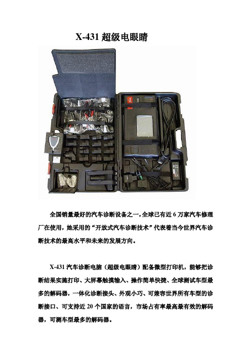
X-431超级电眼睛全国销量最好的汽车诊断设备之一,全球已有近6万家汽车修理厂在使用,她采用的“开放式汽车诊断技术”代表着当今世界汽车诊断技术的最高水平和未来的发展方向。
X-431汽车诊断电脑(超级电眼睛)配备微型打印机,能够把诊断结果实施打印、大屏幕触摸输入、操作简单快捷、全球测试车型最多的解码器,一体化诊断接头、外观小巧、可兼容世界所有车型的诊断接口、可支持近20个国家的语言,市场占有率最高最有效的解码器,可测车型最多的解码器。
让,我们来看看X431的性能。
你,为何不试一试。
可测试60多种国产车系和近200种外国车系,可测试最新奔驰最新宝马测试,奔驰可测试148个系统。
软件在天天升级通过专业网站实现天天升级,每年升级近400个版本,率先推出了CAN-BUS诊断接头,并得到了市场的认可,目前X431网站开通了近20个国家的语言为世界各地用户提供方便快捷的服务,同时X431有很多附加功能;传感器盒(SENSORBOX)的万用表功能、传感器功能、支持PCLINK数据通测试,支持传感器测试盒(SENSORBOX)。
我们看看X431的三大功能;首先是开放式汽车故障诊断功能:支持读码、清码、读取数据流基本功能,其次是网路升级功能,软件每天都在升级,在就是打印功能客户可将测试结果实时打印。
X431的产品结构:由SMARTBOX、微型打印机、主机。
SMARTBOX由接测试主线的接口与测试主线连接,微型打印机由打印出纸口、打印机走纸键、打印机选择键、打印机旋纸按钮、打印纸,主机由热键、电源键、触摸屏、CF卡(由专家版和普通版)、串口(就是9针插口)可通过PC联机线与计算机连接,下面我们演示打印机安纸的过程:第一步:打开打印机的后盖,第二步:打开打印机调节旋钮口,第三步:取出打印机装纸轴,第四步:并把打印纸套在装纸轴上,第五步:将打印机装纸轴装到打印机上,注意:保证打印纸的安装方向正确,顺时针转动进纸旋钮,第六步:把盖子盖上。
X431工作原理资料
X431工作原理资料X431是一种先进的汽车诊断设备,可以帮助技师快速准确地诊断和解决汽车故障。
它采用了一种独特的工作原理,结合了硬件与软件的相互配合,从而实现了高效、智能的诊断功能。
X431的工作原理主要包括以下几个方面:1.采集汽车数据:X431通过连接到汽车的诊断接口,能够实时采集到来自汽车各个系统的数据。
这些数据包括故障码、传感器数据、执行器状态等,用于分析和诊断问题。
2.分析和解码数据:X431的软件会对采集到的数据进行分析和解码,将其转化为可读的故障码和参数数值。
同时,它还能够根据采集到的数据判断可能存在的故障模式,并提供相应的诊断建议。
3.诊断结果显示:经过分析和解码,X431会将诊断结果显示在设备的屏幕上。
诊断结果通常包括故障代码、问题描述、可能的原因以及解决方案等信息。
技师可以根据这些信息进行进一步的诊断和修复工作。
4.数据库与云端支持:X431内置了大量的汽车品牌和型号的数据库,其中包含了详细的故障码解码信息和修复方案。
同时,通过连接到互联网,X431还可以实时获取最新的故障码库和修复方案,以保持诊断的准确性和时效性。
5.特殊功能支持:除了常规的故障诊断功能,X431还具备一些特殊功能,如编程、电子控制单元重置、参数调整等。
这些功能可以帮助技师更好地进行汽车维修和调试。
总的来说,X431的工作原理是通过采集、分析和解码汽车数据,提供准确的故障码和修复建议。
它基于完善的数据库和云端支持,为技师提供了全面而高效的诊断工具。
通过X431的帮助,技师可以更快速、更准确地找出汽车故障,并采取相应的维修措施,提高了维修效率和质量。
元征X-431解码器在汽车防盗系统故障诊断中的应用
(
3)拧点火 钥 匙 到 ON 档,能 听 到 发 动 机 调 节 怠
进行防盗系统和原 ECU 间 的 匹 配,如 图 2 所 示,这 样
ECU 的随机代码才会被新的防盗系统读入并存储,点
作者简介:韩瑞刚 (
1977
G),男,山西太谷人,讲师,硕士,主要从事汽车发动机方面研究.
180
机 械 工 程 与 自 动 化 2020 年第 3 期
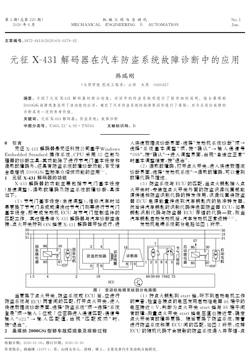
当点火钥匙插入点火开关时安装在点火开关外面的防盗识读线圈起能源传递和防盗识别代码的转发作用识读线圈将防盗器ecu电源能量传送到汽车钥匙内的脉冲转发器然后将汽车钥匙的识别代码传送回防盗器ecu如果钥匙识别代码与防盗器ecu存储的代码一致则当汽车钥匙启动发动机后汽车发动机正常运转2g3
第 3 期(总第 220 期)
关键词:元征 XG
431 解码器;防盗系统;故障诊断
中图分类号:U463
23+4
92∶TN764 文献标识码:B
0 引言
元征 XG
431 解码器是元征科技公司基于 Wi
ndows
EmbeddedS
t
anda
rd 操 作 系 统、
CPU 采 用 32 位 微 处
理器的诊断工具,其 功 能 除 了 进 行 节 气 门 基 本 设 定 和
G05
G20
(
1)拧点火钥匙到 s
t
a
r
t档,听不到启动电机工作
的声音,检查各接点的电压发现启动继电器 86 端子的
电压接近 0V,判 断 为 点 火 开 关 s
t
a
r
t 档 与 86 端 子 间
有故障,测量点火 开 关 s
X431的使用流程
X431的使用流程1. 准备工作在使用X431之前,需要进行一些准备工作,以确保使用顺利进行。
以下是具体步骤:•确保X431设备已充电或连接到电源•检查X431设备的网络连接是否稳定•确保X431设备已安装最新的软件版本•准备车辆的诊断接口线缆并连接到车辆的OBD-II接口2. 打开X431设备将X431设备的电源打开,等待设备启动,进入主界面。
3. 选择车辆品牌和型号在X431设备的主界面上,选择对应的车辆品牌和型号。
如果你不确定车辆的具体信息,可以通过车辆的VIN码进行查询。
4. 进行诊断选择“诊断”功能,X431设备将会与车辆进行连接,并开始进行全面的系统扫描和诊断。
在此过程中,你可以观察设备显示的诊断结果,并查看任何故障码或错误信息。
5. 解读诊断结果根据X431设备显示的诊断结果,你可以进一步了解车辆的问题。
设备可能会列出故障码、系统状态、传感器数据等信息。
根据这些信息,你可以确定车辆的具体问题,并采取相应的维修措施。
6. 提供维修建议根据诊断结果,X431设备还能够提供维修建议。
它可以根据车辆的问题和诊断数据,给出具体的维修指导和建议。
7. 查找技术支持信息如果你在使用X431设备时遇到问题,可以通过设备上的搜索功能查找相关的技术支持信息。
这些信息可能包括维修手册、技术论坛、常见问题解答等。
8. 记录诊断结果为了方便后续的维修工作,你可以在X431设备上记录诊断结果。
这样,你可以随时查看之前的诊断结果,并进行比对分析。
9. 清除故障码如果进行了维修操作,并解决了车辆故障,你可以使用X431设备来清除故障码。
这将会重新启动车辆的系统,并消除之前的故障标记。
10. 结束使用当你完成了对车辆的诊断和维修工作后,可以关闭X431设备,并将诊断接口线缆断开。
同时,记得将设备存放在干燥、通风的地方,以确保设备的安全和维护。
以上就是使用X431设备的基本流程。
通过X431的诊断功能,你可以更准确地找到和解决车辆的问题,提高维修的效率和准确性。
X431宝马诊断软件特殊功能介绍
X431宝马诊断软件特殊功能介绍元征软件宝马开发工程师李游幸宝马汽车无论从车型设计、整体性能、操控性还是舒适性等方面始终遥遥领先于世界水平。
BMW 3系列更是荣获2006年度“世界年度车型”奖。
然而采用高科技电子控制技术提高汽车性能的同时也使汽车变得更加复杂,出现故障也使维修工作变得更加困难,需要更专业的维修技师借助先进的仪器来完成。
为此深圳元征科技股份有限公司推出X431,ADM等系列汽车故障诊断仪器设备,为汽车维修人员提供强力的帮助,深受用户喜爱。
本文即简要介绍X431中宝马诊断软件,尤其是特殊功能的使用说明。
首先简单介绍宝马汽车的诊断座位置、形状及底盘的识别标志位置。
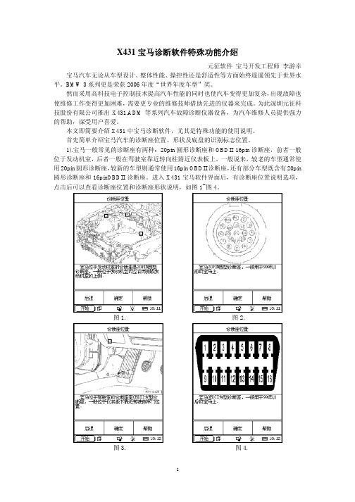
1).宝马一般常见的诊断座有两种:20pin圆形诊断座和OBDII 16pin诊断座,前者一般位于发动机室,后者一般在驾驶室靠近转向柱附近仪表板上。
一般说来,较老的车型通常使用20pin圆形诊断座,较新的车型则通常使用16pin OBDII诊断座,还有部分车型既含有20pin 圆形诊断座和16pinOBDII诊断座。
进入X431宝马软件界面后,有诊断座位置说明选项,点击后可以查看诊断座位置和诊断座形状说明,如图1~图4。
图1. 图2.图3. 图4.2). 宝马的底盘通常分有: 1系列的E87,3系列的E30、E36、E46和E90,5系列的E28、E34、E39和E60/E61,6系列的E24和E63/E64,7系列的E23、E32、E38和E65/E66,8系列的E31,X系列的X3 (E83) 和X5 (E53) ,Z系列的Z1 (E30) 、Z3 (E36) 、Z4 (E85) 和Z8 (E52) ,以及MINI。
除了MINI容易识别外,其他底盘一般都标记在车头盖或后尾行李箱的支撑柱上,即打开车头盖或者后尾行李箱,分别有两根圆形小柱支撑着它们,在上面可以找到如5系列的“E39”等字样。
在使用X431诊断宝马汽车的过程中,绝大部分客户对于读故障码、清故障码、数据流,以及部分动作测试等功能的使用都已非常熟练,而且简单易懂。
x431的应用电路及工作原理
x431的应用电路及工作原理1. 概述x431是一种常见的汽车故障诊断工具,广泛应用于汽车维修工作中。
本文将介绍x431的应用电路和工作原理。
2. 应用电路x431的应用电路主要由以下几个部分组成:2.1. 传感器x431内部集成了多个传感器,用于检测车辆各种参数,如发动机转速、温度、氧气含量等。
传感器将检测到的信号转换成电信号,并传递给下一级的电路处理。
2.2. 信号处理电路x431的信号处理电路负责接收传感器传来的信号,并进行滤波、放大、分析等处理。
处理后的信号会被发送到微处理器进行进一步计算。
2.3. 微处理器微处理器是x431的核心部件,负责控制整个系统的运行和数据处理。
微处理器会根据接收到的信号和存储的故障代码库进行比对,最终给出对车辆故障的诊断结果。
2.4. 通信模块x431的通信模块与车辆的OBD(On-Board Diagnostics)系统进行通信,以获取车辆的实时数据和故障代码。
通信模块使用标准的OBD协议进行通信,确保与不同品牌和型号的车辆兼容。
3. 工作原理x431的工作原理可以简单描述如下:1.用户连接x431与需要诊断的车辆之间的OBD接口。
2.x431通过通信模块向车辆发送请求,获取车辆的实时数据和故障代码。
3.传感器感知车辆各种参数,并将信号传递给x431的信号处理电路。
4.信号处理电路对传感器信号进行处理,然后发送给微处理器。
5.微处理器根据接收到的信号和存储的故障代码库进行比对,最终给出车辆故障的诊断结果。
6.x431将诊断结果显示在设备屏幕上,并提供详细的故障码解释和修复建议。
x431的工作原理借助了先进的电子技术和车辆数据分析算法,能够高效准确地诊断车辆故障,并给出相应的解决方案。
4. 总结x431是一种汽车故障诊断工具,其应用电路和工作原理基于传感器、信号处理电路、微处理器和通信模块等组成。
通过连接到车辆的OBD接口,x431能够获取车辆的实时数据和故障代码,并根据存储的故障代码库进行比对和诊断,最终给出解决方案。
X431数据记录功能介绍
X431数据记录功能介绍元征软件贺鹏麟X431的功能之强大在汽车维修领域是有目共睹的,其中最实用的有以下几条:1.测试车型最多(可测几乎所有国产车型和亚欧美各类型进口车)。
2.测试质量高(测试数据准确,精度高、速度快)。
3.测试范围广(奔驰可测项目多达148项)。
4.测试技术领先,率先推出CAN-BUS诊断接头(CAN BUS和VOLVO CAN-BUS诊断接头)。
5.升级速度快(天天发行新的诊断软件)。
6.具有数据流记录、保存、回放功能。
其中前面5条用户可能都比较熟悉,但第6条由于是元征公司后续开发的,很多用户都不熟悉甚至不会使用,而该功能在解决汽车间歇性故障中又非常适用,所以这里有必要对此功能的使用条件,操作方法和技巧等做一简要介绍。
要使用此功能,必须到 网站下载升级14.10或以上版本的显示程序。
进行数据记录前必须保证CF卡上有足够的剩余存储空间(一般情况下连续记录100条数据流1小时大约需要2M 空间)。
关于如何查看CF卡剩余空间,请参阅X431使用说明书。
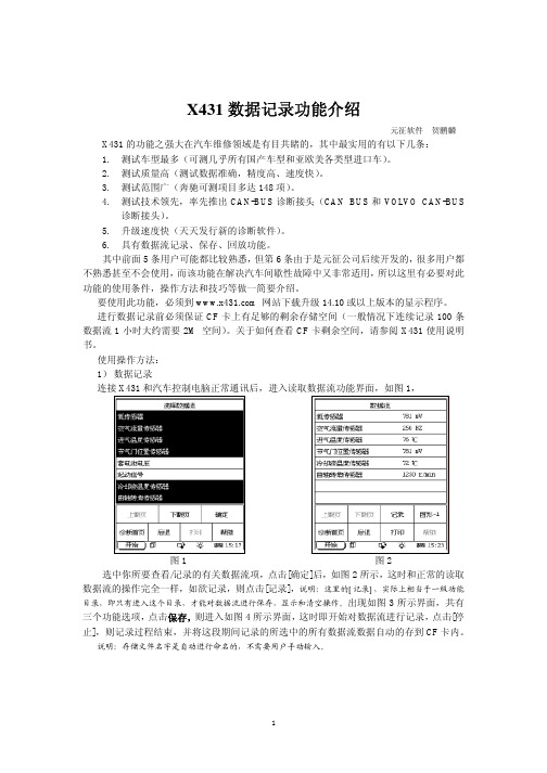
使用操作方法:1)数据记录连接X431和汽车控制电脑正常通讯后,进入读取数据流功能界面,如图1,图1 图2 选中你所要查看/记录的有关数据流项,点击[确定]后,如图2所示,这时和正常的读取数据流的操作完全一样,如欲记录,则点击[记录],说明:这里的[记录],实际上相当于一级功能目录,即只有进入这个目录,才能对数据流进行保存,显示和清空操作。
出现如图3所示界面,共有三个功能选项,点击保存,则进入如图4所示界面,这时即开始对数据流进行记录,点击[停止],则记录过程结束,并将这段期间记录的所选中的所有数据流数据自动的存到CF卡内。
说明:存储文件名字是自动进行命名的,不需要用户手动输入。
图3 图4 2)数据显示如要显示/查看以前记录的数据,必须要保证X431能够进入到读取数据流的功能界面,即只有在此功能下,才能进入曾经存储数据的目录并访问相关存储记录的文件。
X431奇瑞轿车专用诊断仪说明书XXXXZGP20040406英

CHERY CAR X431-CHERYContentsPart A: Diagnostic Program (1)Part B: Software Update (14)Part C: Main Unit (22)FAQ (45)Part A: Diagnostic ProgramContentsIntroduction (2)Features (2)Advanced (2)Open (2)Integrative (2)Flexible (2)Hardware Configuration (2)Name (3)Name (3)Ports and Indicators (3)Printer Operation (4)Mounting Paper (4)Printing Test Result (5)Explanation of Buttons (5)Button Descriptions (5)Conditions for Test (5)Select Diagnostic connector (5)Diagnostic Socket Location (6)Pin Definitions (6)Connection (6)Operation (7)Entering Function Menu (7)Read Fault Code (10)Clear Fault Code (10)Data Stream (10)Actuation Test (12)IntroductionX431 is a newly developed automobile diagnostic computer. It is based on the technology of open diagnostic platform, the most advanced automobile diagnostic technology brought forward by our company. The open diagnostic platform represents the highest level of automobile diagnostic technology, and is the developing trend of this field in the future.FeaturesAdvancedX431 is the most advanced automobile diagnostic unit in the world at present. It is designed compactly with modern outline and large LCD touch screen. Demountable printer makes the operation easy. The product is a result of combination of the automobile industry and the communication technology, which starts the new development trend in the automobile diagnosis field. This product not only provides a new way of automotive diagnosis for vehicle service station, but also becomes a favorable choice for “DIYers”.Open●Open operating system. That is, X431 isan open automobile diagnostic platformwith multifunction and multi-languagebased on LINUX operation system.●X431 provides open interface to supportthe third party‟s development. IntegrativeX431 has all functions of PDA. Handwriting input, personal database, vast vocabulary English-Chinese dictionary.The super capacity database can realize multi-purpos e management of user‟s information.FlexibleX431 has a fire-new modern design. Each function can be combined with others at will or used independently.●The main unit and the diagnostic box canbe used independently.●The main unit itself is equal to a PDA,which has the functions of personaldatabase, etc.●The SMARTBOX can be connected to PCto perform automobile diagnosis when it isdemounted from the main unit. Thediagnostic software used by PC can evenbe downloaded on the our website. That is,the SMARTBOX can be sold independently.This is an important feature of X431.● A standard RS232 interface is used toconnect the SMARTBOX and its upper unit.So more BOXes can be designed toincrease functions, such as SENSORBOX,REMOTEBOX, etc. This feature increasesthe value of X431.●MINIPRINTER is detachable. User can useit to print out data.As described above, the independent use of the main unit and the SMARTBOX (or other diagnostic box) is the extraordinary and creative feature of X431.Hardware ConfigurationThe hardware configuration of X431-CHERY is as shown in Figure 1-01.Figure 1-01Printer OperationMounting PaperMINIPRINTER uses heat sensitive paper with size of Φ30×57mm (internal hole Φ7mm). Refer to Figure 1-03a to Figure 1-03d for mounting the paper.1. Open the paper lid on the back of the printer. See Figure 1-03a.Figure 1-03a2. Take out the spindle and mount the paper scroll onto the spindle. See Figure 1-03b.Figure 1-03b3. Put the paper spindle into the printer with correct direction. The paper may not be fed if the direction is wrong. See Figure 1-03b and Figure 1-03c.Figure 1-03c4. Open the side plate, pull up the pressing rod and lead the paper into slot. Turn the feed knob clockwise until the paper comesout of the outlet. See Figure 1-03d.Figure 1-03d5.Push down the pressing rod, mount theside plate, attach the paper lid, and thenconnect the printer to the X431 main unit. Printing Test ResultThere are two indicators on the printer:1.[SEL]:to show the readiness of the printer.2.[POWER]:the power indicator of the printer.If the [SEL] indicator is not lit, you can press the [SEL] button to turn it on and make the printer ready.When the [SEL] indicator is lit, it shows that the printer is ready. Click the [PRINT] button (if it appears) on the screen of X431 main unit to print the test result.Explanation of ButtonsButton DescriptionsThe main buttons on the operation interface and their functions are as follows: [BACK]: to return to the previous interface. [START]: to do the next operation. [EXIT]: to exit the diagnostic program. [OK]: to confirm and execute. [CANCEL]: to cancel present operation and return to the previous interface.[PAGE UP]: to display the previous page. It is inactive if the current page is the first page. [PAGE DOWN]: to display the next page. It is inactive if the current page is the last page. [HOME]: return to the main interface. [PRINT]: to print the test result.[BOX INFO]: to show the version information of SMARTBOX.[HELP]: to display the help information. [RETRY]: to do the unfinished operation once again.Conditions for Test●The voltage of vehicle battery should be11-14V. The rated voltage of the X431 is12V.●Turn off all electric devices such as A/C,headlight, stereos etc.●The throttle should be in the closedposition.●The ignition timer and idle speed shouldbe in the standard range; the coolanttemperature should be 90-110℃and thetransmission fluid temperature should be50-80℃.Select Diagnostic connector ●Select [Fiat-3] connector for diagnosingCHERY car with 3PIN diagnostic socket.●Select [Mitsubishi-12+16] connector fordiagnosing Mitsubishi electronic controlsystems equipped on CHERY B11 series.●Select [Smart OBDII-16] connector fordiagnosing other electronic controlsystems of CHERY car with 16PINdiagnostic socket.Diagnostic Socket Location● Fiat-3 diagnostic socket is in the enginecompartment.● The OBDII-16PIN diagnostic socket isusually located in the cab under the instrument panel at the left side.Pin DefinitionsThe Fiat-3 diagnostic socket is as shown in Figure1-04.Figure 1-04The OBDII 16PIN diagnostic socket is as shown in Figure 1-05.Figure 1-05Connection● Insert the CF card into the CF card slot(Note: keep the face labeled “UPSIDE ” upward), and make sure the card is fully seated.● Insert one end of the main cable into thediagnostic socket on SMARTBOX.● Connect the other end of the main cableto the [Smart OBDII] diagnostic connector. ● Connect the other end of the diagnosticconnector to the 16PIN OBDII diagnostic socket.Note:If the power supply on vehicle diagnostic socket is insufficient or the power pin is damaged, you can get power in the following ways:♦ From cigarette lighter: insert one end of the cigarette lighter cable into the lighter socket in vehicle and connect the other end to the power connector of X431 main cable.♦ From battery: clamp the two clips of battery cable on the positive and negative poles of battery and insert another end of the cable into the power connector of X431 main cable.♦ From power adapter: connect the power adapter to the 100-240V AC outlet with power cord. Insert the 12V DC plug of power adapter into the power connector of X431 main cable.OperationEntering Function Menu After connection, press [POWER] key to start X431.After starting the main unit, press [HOTKEY] (or click [Start] button on the main menu, and select [GAG]→[GD Scan] on the pop-up menu). The screen will display the home page of vehicle diagnosis as shown in Figure 1-06.Figure 1-06Button descriptions:♦[QUIT]: to exit the diagnostic program. ♦[BOX INFO.]: to display hardware and software version of SMARTBOX.♦[HELP]: to display help information.♦[START]: to start the diagnosis.Click [START] button, the screen will display the icon of vehicle make as shown in Figure 1-07.Figure 1-07Button descriptions:♦[BACK]: to return to the previous interface.♦[PAGE UP]: to display the previous page, it is inactive if the current page is the first page.♦[PAGE DOWN]: to display the next page, it is inactive if the current page is the last page.♦[HELP]: to display the help information. Click the icon of vehicle make. The screen will display the message as shown in Figure 1-08.Figure 1-08The software can diagnose ENG, ABS, SRS, AT, immobilizer systems and so on of all CHERY models before 2003.Click [OK ] button.X431 begins to reset and check the SMARTBOX, and download the diagnostic program from the CF card. After download, the screen will display the message as shown in Figure 1-09.Figure 1-09Button descriptions: [OK]: to go on test .vehicle models menu as shown in Figure 1-10.Figure 1-10The machine can diagnose A11, A15, B11 and S15 series.Note:The test procedure for each vehicle model is similar, so we only take A11 series as an example to describe the operation. Refer to the example and the prompts on the screen when testing other series.Click [A11 series]. The screen will display the system menu as shown in Figure 1-11.Figure 1-11Engine, SRS and ABS systems of A11 series can be diagnosed.Note:The test procedure for different system is similar. So here wetake “Engine-MM SPI ” as example to describe the operation.Click [Engine]. The screen displays the engine menu as shown in Figure 1-12.Figure 1-12show prompt toselect diagnostic connector. See Figure 1-13.Figure 1-13[Fiat-3] diagnostic connector should be used for diagnosing MM SPI engine. When the connector is well plugged, click [OK] button. Then the screen will display the function menu as shown in Figure 1-14.Figure 1-14The following functions can be performed:1.Read fault code.2.Clear fault code.3.Data stream4.Actuation testClick corresponding item to perform the function.Read Fault CodeClick [Read Fault Code] in the function menu shown in Figure 1-14. X431-CHERY starts to read fault code. The screen will display the result if the reading is successful. Figure 1-15 shows an example of the test result.Figure 1-15If printer is ready, the displayed result can be printed out by clicking [PRINT] button. Button description:♦[HOME]: to return to the home page of vehicle diagnosis.♦[BACK]: to goback to the previous interface.♦[PRINT]: to print out the test result. Clear Fault CodeClick [Clear Fault Code] in the function menu shown in Figure 1-14. X431-CHERY starts to clear the fault code. The screen will display the message as shown in Figure 1-16.Figure 1-16When the fault code is cleared successfully, the screen will display the message as shown in Figure 1-17.Figure 1-17Click [OK] button to return to the function menu.Data StreamClick [Data stream] in the function menu shown in Figure 1-14. The screen will display the data stream menu of the tested system.Click one or more items that you want to see. The selected items will be highlighted as shown in Figure 1-18.Figure 1-18Button description:♦ [PAGE DOWN]: to display the next page of data stream items.♦ [HOME]: to return to the home page of vehicle diagnosis.♦ [BACK]: to go back to the previous interface.♦ [OK]: to display the live value of the selected data stream items.Click [OK ] button. The screen displays the live value of the selected data stream items, as shown in Figure 1-19.Figure 1-19Button description:♦ [GRAPHIC-1]: to display the waveform of a data stream item.♦ [HOME]: to return to the home page of vehicle diagnosis.♦ [BACK]: to go back to the previous interface.♦ [PRINT]: to print the test result.In the interface of data stream display, click [GRAPHIC-1] to display the waveform of the data stream item. Figure 1-20 shows an example.Figure 1-20Button description:♦ [PAGE DOWN]: to display the waveform of next data stream item.♦ [GRAPHIC-2]: to display the waveforms of 2 data stream items.♦ [HOME]: to return to the home page of vehicle diagnosis.♦ [BACK]: to go back to the previous interface.♦ [PRINT]: to print the test result.In the interface of single waveform display, click [GRAPHIC-2] to display the waveforms of 2 data stream items for live comparison between two correlative data stream items.Figure 1-21 shows an example.Figure 1-21Note:♦ The screen will display the live value of data stream again if the [DIGITAL] button is clicked in the interface.♦ The three display modes -- [DIGITAL], [GRAPHIC-1] and [GRAPHIC-2] can be switched in turn.Actuation TestClick [Actuation test ] in the function menu shown in Figure 1-14. The screen will display the list of actuators for test. See Figure 1-22.Figure 1-22Click one item to perform the test each time. During the test, operator may feel the action of the actuator by seeing or hearing.When the actuation test is complete, the screen will display the massage as shown in Figure 1-23.Figure 1-23Click [OK] button to return to the menu.Part B: Software UpdateContentsUpdate of Diagnostic Software (15)Hardware Requirement (15)User Registration (15)Read Terms of Service (15)Fill in Necessary Information (16)Member Login (16)Member Area (17)Account Administration (17)Product Control (17)User‟s Information Maintenance (17)Order Information (17)Logout (17)Software Download (17)Software Update (19)Remaking of X431 CF card (20)Appendix: Flow Chart of X431 Upgrade (21)Update of DiagnosticSoftwareThe Internet update function of X431 can letthe user conveniently and quickly downloadthe software from our website for update.We put the latest version of software to www.x431. com and display the massage on thenews page. User can use computer to visit theWebsite in any part of the world. Afterregistration, the latest version of software canbe downloaded. Then user can update hisX431 by unzipping and installing the software.Hardware RequirementThe following necessities should be madeready:1. A computer that can be connected toInternet.2. A CF card reader/writer and a CF card thatneed to be updated.See Figure 2-01 for hardware connection.Figure 2-011-CF card reader/writer 2-USB cable3-USB Port 4-Computer 5-CF card1.I nsert the CF card into the CF cardreader/writer.2.C onnect one end of the USB cable②tothe port of the CF card reader/writer①,and the other end to the USB port of thecomputer.User RegistrationLog on www. x431. com. See Figure 2-02Figure 2-02Select the favorite language in the pull-downmenu at the lower right of the interface toenter the homepage. See Figure 2-03.Figure 2-03Read Terms of ServiceClick “Register” in the interface shown inFigure 2-03 to open the window as shown inFigure 2-04.Figure 2-04Note:When the member purchases one or moreproducts after registration, he should logonto the member area, and then click“product control” to register the newly purchased product.Refer to the section “Member login”.The terms of service is shown in the screen. After reading and fully understand it , click “I accept” button to enter the interface shown in Figure 2-05.Fill in Necessary InformationFill in the serial No. of SMARTBOX, registration No. and dealer code in the interface shown in Figure 2-05.Figure 2-05The serial No. of SMARTBOX is marked on the back of SMARTBOX. The registration No. is in an envelope delivered withthe product (the number must be kept confidential). The dealer code is attached on the last page of the user‟s manual.After the information is filled, click “Next step” to enter the next interface shown in Figure 2-06.Note:When a product is sold, the dealer will log onto www. x431. com and enter the dealer code in the “Dealer administration” area so that the user can do effective registration later. User should contact the dealer if registration can not be done effectively.Figure 2-06If the filled serial No. or registration No. isinvalid, the screen will display the message asshown in Figure 2-07. Click “OK” button to return to the previous interface to re-fill the correct numbers.Figure 2-07After information are filled in the interface shown in Figure 2-06, click “Next step” to enter the next interface. See Figure 2-08.Figure 2-08Fill in the username and password. Then click “OK” button to enter the interface shown in Figure 2-09.Figure 2-09Up to now, the registration is completed. Click “Login“ to perform further operation or click “Close” to exit.Note:Only the registered user can download and update the software .Member LoginThe user becomes the registered member after registration.Member can log in the website by fillingusername and password in the interface shown in Figure 2-03. Click if you forget your necessary information in the pop-up dialogue box shown in Figure 2-10.Figure 2-10Note:The E-mail account is very important as our webmaster will send the username and password to the account.Member AreaWhen a registered member purchase one or more new products, it is not necessary to click “Register”on the homepage to register the newly purchased product. Instead, he can enter username and password to log in, and then click “member” in the interface shown in Figure 2-11 to get into the member area. See Figure 2-12.Figure 2-11Figure 2-12The member can perform the following function:● Account administration ● Product control● User‟s information maintenance ● Order management ● LogoutAccount Administration It is for changing password.Product ControlThe following tasks can be performed for “Product Control” function:● Register newly purchased product.● Hand over the machine to other customer. ● Click serial No. to see the currently available software version.User’s Information Maintenance It is for renewing the user‟s information.Order InformationIt is for checking the unpaid order.LogoutWhen clicking “Logout”, the system will pop up a dialogue box as shown in Figure 2-13.Figure 2-13Click “OK” button to return to the hompage.Software DownloadNewly registered user can download, free of charge, the same software as that installed in the purchased main unit, or the available later version of the software.After filling in the username and password, click “Login” to enter the interface as shown in Figure 2-14.Click here to enterFigure 2-14Select the SMARTBOX No. in Figure 2-14 and then click “Next step” to enter the web page of software download.The screen will show a list of software and different versions for downloading. See Figure 2-15. If no later version is released, the item will be marked “Not ready”.Figure 2-15Select the latest version and click “Check” button or “Download” icon to open the function introduction page for the software. The information on the page includes new function, tested vehicle, hardware requirement, etc. See Figure 2-16.Figure 2-16A new page will appear when user clicks “Download Linux version” button. The pop up window will show the description for updating the downloaded software. See Figure 2-17.Figure 2-17Click “Download” button to save the software into the u ser‟s computer.It is necessary to download the “X431 Update tool” and put it in the same folder (e.g. “X431 update” folder) as other downloaded software if it does not exist in your computer. It is going to be used later during updating.Precaution on operation of the CF card reader/writer:1)Install the driverIf it is the first time to use the CF card reader/writer, you may have to install its driver. Use CD-ROM or floppy disk which are bought separately or delivered with the CF card reader/writer to install the driver.CF card reader/writer can use the default driver in Windows Me/2000/XP and Mac OS 9.x/Mac OS X. However, it is necessary to install the driver on Windows 98.The installation procedure is as follows: 1. Boot Windows 98.2. Insert the CD-ROM into CD-ROM drive.3. Connect CF card to the USB port of the PC with the attached USB cable.4. Find and Double click on setup.exe file in the catalogue of CD-ROM. The system will make preparation for the installation. See Figure 2-18.Figure 2-185. When the preparation is complete, the screen will prompt to continue the operation. See Figure 2-19. Click “Next” to start installation.Figure 2-196. When installation is finished, the screen will display the information as shown in Figure 2-20. Click “Finish” t o exit.Figure 2-20When the CF card reader/writer is installed successfully, a “Removable disk” icon will be added in the catalogue of “My computer”.Note:♦ Do not unplug the CF card reader/writerfrom the USB port while its LED is blinking, otherwise data would be damaged!♦ Data on CF card cannot be restored fromthe “Recycle Bin” once deleted.2)Pull out the CF cardThe CF card must not be pulled out when the CF card reader/writer is being used. Otherwise, the data in the CF card will be lost.Procedure for pulling out the CF card:On the desktop of Windows, open the window of “My computer”. Click the right mouse button on “Removable disk” to pop up a menu. Select“Ejector (J)” in the menu. Then pull out the CF card. Thewritten data may be lost if the CF card is pulled out discretionarily. When you want to use the CF card again, put it in.Software UpdateOpen the “X431 update” folder, and doubleclick the icon . Then install the update tool according to the prompts on the screen.When the complete,the “X431 update tool” icon will appear onthe desktop.Make sure that the X431 CF card reader/writer and the CF card are well connected to the tool” ico n to run the program.The program will automatically check the downloaded update files, including the diagnostic program and the display program. See Figure 2-21.Figure 2-21Select the module for update in the interface shown in Figure 2-21, and cl ick “Update” icon to update. When the update is complete, prompts will appear to notify successful update.Description of icons at the lower left of the interface:♦ Source folder : to show the routethat the update program is from. The default one is where the last software from.♦ Target folder : to show the route thatthe update program will be installed. It isCF card in this situation. It is necessaryto click this button to designate theremovable disc when laptop computer isused.The required space and available space are listed at the lower left of the interface. If the available space is not enough to perform the operation, click to show the installed programs. See Figure 2-22.Figure 2-22Select the programs that can be deleted and click “Delete” button to make some more space available.Remaking of X431 CF cardIn case X431 CF card is damaged and the program in the card can not be used, please use the following procedure to make a new CF card:1.Log onto the website "www. x431. com".Enter your username and password to login.Select the SMARTBOX No., and thendownload the following programs into yourcomputer:1) Necessary programs for making CF card:●X431 UPDATE TOOLS---- for writingthe program from computer to CFcard when doing X431 update●DISPLAY PROGRAM---- fordisplaying the X431 diagnosticinformation and managing the X431diagnostic programs●SYSTEM DATA---- system dataused by X431 system2)Optional programs that can be selectedaccording to user's demand:Diagnostic program for various vehicles 2.Install the X431 UPDATE TOOLS intocomputer.3.Format the X431 CF card.4.Run the X431 UPDATE TOOLS and writethe display program, system data and diagnostic programs onto CF card.Appendix: Flow Chart of X431 UpdatePart C: X431 Main UnitContentsLayout of Main Unit (23)Introduction (24)Interface (24)Input (25)Using the Soft Keyboard (25)Input by Keyboard (26)Input by Writing Board (26)Control of App (26)Check Box (26)Scrolling Bar (27)Common Button (27)Help (27)Tool and Game (27)Tools (27)Calculator (27)World Time (28)Dictionary (29)Picture View (29)Game (30)FIR (30)Reversi (30)PIM (31)Memo (31)Add New Memo (31)View Memo (31)Edit Memo (32)Delete Memo (32)Edit Type (32)Browse By Types (32)Address (32)Add New Address (33)View Address (33)Edit Address (33)Delete Address (34)Search Address (34)To Do (34)Add New To Do (35)View To Do (35)Edit To Do (35)Delete To Do (35)Edit Type (36)The Set of display (36)Schedule (36)Add New Schedule (37)View Schedule (38)Edit Schedule (38)Delete Schedule (38)System (39)Control Panel (39)Application (39)Power Management (40)Clock (41)Contrast (42)Language (42)System Information (43)Calibrate Touch screen (43)User Register (43)About (43)Shut Down (44)Vehicle Maintaining (44)Vehicle Decoding Device (44)Sensor Testing and Simulating (44)FAQ (45)About Update via Internet (45)About Hardware (46)About System Setting (47)About Operation (48)Questions Related to Vehicle (49)Layout of Main UnitFigure 3-01Touch ScreenPaper OutCF Card SlotEjectorDATA I/OPaper InPrinter adjustorSerial Port 1Hot Key Power ButtonIntroductionInterfaceTurn on the power source, and then press [Power] key on the machine. The screen will display the prompts about touch screen calibration. Press [Hot] key (refer to the section “Calibrate Touch screen”for detailed steps) if you want to make calibration, otherwise, you can wait until it displays the start interface as shown in Figure 3-02.Figure 3-02 Note:An interface for User Register will be displayed when the machine is started at first time. Refer to the section “User Register” for detailed steps.When you want to turn off the machine, press and hold [Power] key for at least 2 seconds.[Start] button: Its function is the same as that in Windows. Click it to pop up the start menu. The items and their respective functions in the menu are shown in the following table.[] Active Taskbar Icon: Click it by stylus to display and switch the executed programs. [] Back Light Icon: Click it to turn on/off back light.[] Soft Keyboard Icon: Click it to activate the soft keyboard. Then you have two ways to choose:1.Input by soft keyboard;2.Input by writing board.InputNote: To input data, please activate SoftKeyboard with stylus and use the stylus in the subsequent operations.Using the Soft Keyboard Activate and HideYou can click Soft Keyboard icon on the bottom of the touch screen to activate the soft keyboard, and click again to hide it.Input by Soft KeyboardYou have two ways to choose. One is to input by Soft Keyboard just like normal keyboard, but with stylus instead of finger. The other is to input by writing board.Click [En] button, it will switch from normal keyboard to writing board [Hw]. And click [Hw] button, it will switch back.The Function KeyThere are four function keys on the upper-right of the Soft Keyboard. SBC/DBC case, punctuations, Keyboard/Writing board, and the Soft Keyboard position can be determined by clicking one of the four keys for each of the functions from left to right. (Refer to Figure 3-03)The four function keys at the upper-middle position are for moving the cursor leftward, rightward, upward or downward.Figure 3-03In keyboard mode, the key at the bottom left of the keyboard is [Shift] key. Click it to change the lowercase letter into the uppercase letter, and the numeral key into special symbol。
元征431发动机诊断仪说明书

X431产品介绍(微卡培训)

一、产品简介 二、产品结构 三、产品功能 四、技术介绍 五、技术参数
六、产品展示
七、产品应用 八、产品特点 九、注意事项
一、产品简介
X-431电脑检测仪是全球销量最好的汽车诊断电脑 之一,全球已有近二十万家修理厂在使用,他所采 用的“开放式汽车诊断技术”代表着当今世界汽车 诊断技术的最高水平和未来发展方向,是汽车诊断 的最佳解决方案。
读取数据流: 根据不同的故障现象选择最关键的数据
读取数据流:根据不同的故障现象选择最关键的数据
读取数据流:根据不同的故障现象选择最关键的数据
读取数据流:根据不同的故障现象选择最关键的数据
读取数据流:根据不同的故障现象选择最关键的数据
数据流记录/对比
数据流记录/对比
数据流记录/对比
数据流记录/对比
点击[开始] 。
屏幕显示车系选择菜单。以朝柴 为例进行演示,点击朝柴车标。
选择诊断程序版本,点击[确定]。
系统及SMARTBOX初始化。
选择[控制模块]。
选择[合适的诊断接头]。
根据实际修车情况选择不同的功能菜单
X431读取故障码
清除故障码
读取数据流:根据不同的故障现象选择最关键的数据
操作系统: CPU: CF卡内存: 主机接口: 主机电源: 主机功率: 显示屏幕:
屏,带背光
LINUX操作平台 32位微处理器 128 M 标准串口/并口 DC12V 约9W 240×320大屏幕LCD,带触摸
六、产品展示
连接X-431。
按 [POWER]键,开机。
按[HOTKEY]键(或点击[开始] → [诊断 程序]→[汽车解码程序])进入汽车诊断 主界面。
汽车故障诊断新利器——元征X-431 Diagun诊断枪

汽车故障诊断新利器——元征X-431 Diagun诊断枪
佚名
【期刊名称】《《汽车与驾驶维修:维修版》》
【年(卷),期】2009(000)010
【摘要】2009年3月,国内最大的汽车诊断设备制造商之一——深圳市元征科技股份有限公司,正式向中国市场发布了新一代汽车故障诊断新品——X-
431Diagun诊断枪。
该产品体积小巧、功能强、便于携带,一经上市便引起了诊断市场各方的高度关注。
【总页数】1页(P98)
【正文语种】中文
【相关文献】
1.测评元征X431 GX3汽车故障诊断仪 [J], 孙磊
2.测评元征X-431 Diagun汽车故障诊断枪 [J], 王全蕾
3.现代汽车故障诊断的利器——汽车示波器 [J], 王加升
4.汽车故障诊断新利器——元征X-431 Diagun诊断枪 [J],
5.元征X-431解码器在汽车防盗系统故障诊断中的应用 [J], 韩瑞刚
因版权原因,仅展示原文概要,查看原文内容请购买。
x431使用技巧

x431使用技巧X431是一款汽车诊断工具,广泛应用于汽车修理行业。
下面是一些X431的使用技巧。
1. 确保连接稳定:使用X431之前,要确保诊断仪与车辆的连接稳定。
可以使用诊断仪上的电源插头连接到车辆的OBDII 接口,或者使用诊断仪上的USB线连接到电脑。
2. 选择正确的车型:打开X431软件后,要选择正确的汽车品牌和车型。
如果选择错误的车型,可能无法进行正确的诊断。
3. 进行全面的系统扫描:X431可以对车辆的各个系统进行全面的扫描,包括发动机、变速器、制动系统等。
在进行系统扫描之前,需要等待一段时间,让诊断仪与车辆进行通信。
4. 读取故障码:X431可以读取车辆的故障码,帮助用户快速定位故障。
读取故障码后,可以查看故障码的描述和建议的维修方法。
5. 清除故障码:在修复故障后,可以使用X431清除车辆的故障码。
清除故障码后,可以重新进行系统扫描,确保故障已经修复。
6. 查看实时数据:X431可以显示车辆的实时数据,包括发动机转速、车速、冷却液温度等。
通过查看实时数据,可以判断车辆是否正常工作。
7. 进行特殊功能:X431还具有一些特殊功能,如喷油器编程、刹车片更换提醒等。
这些特殊功能能够帮助用户更方便地维修车辆。
8. 更新软件:为了保持X431的诊断能力,需要定期更新软件。
可以通过连接到互联网,下载最新的软件更新。
9. 学习使用手册:X431有详细的使用手册,用户可以通过学习手册了解更多的使用技巧和注意事项。
掌握这些技巧能够更好地使用诊断仪。
总之,X431是一款功能强大的汽车诊断工具。
通过学习使用技巧,可以更高效地使用X431进行车辆诊断和修复。
元征X-431 PAD Ⅲ实测:上汽荣威i5气囊在线编程
栏目编辑:高中伟 gzw@Diagnosis & Inspection检测技术及设备48-CHINA ·April元征X-431 PAD Ⅲ实测:上汽荣威i5气囊在线编程元征X-431 PAD III是一款具有“智能诊断”和“在线编程”功能的高端汽车故障诊断工具,具有特殊功能多、车型覆盖广、测试数据准确、诊断功能强的特点。
在线编程无需原厂账号,不产生费用,对车辆ECU模块无损害。
适用范围支持车型为上汽荣威i5,2017-2019款车型。
功能介绍升级ECU版本或者对空白ECU写入数据, 此功能对蓝牙通讯信号要求较高,信号不好会导致刷写过程中断线, 测试时应保证车辆蓄电池电压充足。
条件需求重新编程。
软件版本选择上汽荣威V13.00及以上版本。
产品要求元征X-431 PAD III系列产品。
操作步骤说明:在线编程的完成一般分为三个步骤:编程、配置和设置,需要顺次执行完成这三项。
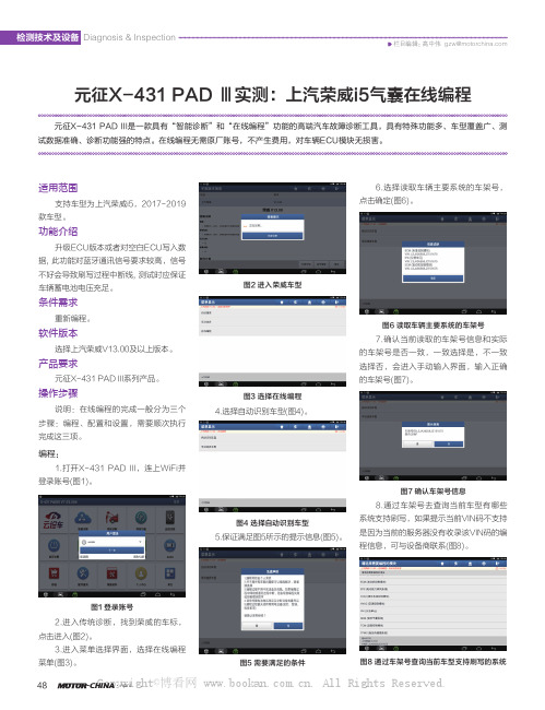
编程:1.打开X-431 PAD III,连上WiFi并登录账号(图1)。
图1 登录账号2.进入传统诊断,找到荣威的车标,点击进入(图2)。
3.进入菜单选择界面,选择在线编程菜单(图3)。
图2 进入荣威车型图3 选择在线编程4.选择自动识别车型(图4)。
图4 选择自动识别车型5.保证满足图5所示的提示信息(图5)。
图5 需要满足的条件6.选择读取车辆主要系统的车架号,点击确定(图6)。
图6 读取车辆主要系统的车架号7.确认当前读取的车架号信息和实际的车架号是否一致,一致选择是,不一致选择否,会进入手动输入界面,输入正确的车架号(图7)。
图7 确认车架号信息8.通过车架号去查询当前车型有哪些系统支持刷写,如果提示当前VIN码不支持是因为当前的服务器没有收录该VIN码的编程信息,可与设备商联系(图8)。
图8 通过车架号查询当前车型支持刷写的系统Copyright©博看网 . All Rights Reserved.高中伟 gzw@Diagnosis & Inspection 检测技术及设备2021/04·汽车维修与保养499.选择SDM(安全气囊),显示对应的编程菜单(图9)。
项目九 X431诊断仪

图7
图8
(6) 进入诊断程序界面,如图9;由于对诊断车辆和发动机的型号较为熟悉,可进入传统诊断模 块根据具体车系和品牌、名称进行选择,根据此次实习车辆型号只需进入中国车系选择一汽大 众即可,如图10。
注意:如果对车辆具体型号不太了解,X431提供智能识别,只需进入智能诊断页面即可。
图9
图 10
(7)选择完车系和车型以后进入到功能选择页面,此时故障现象为发动机故障灯点亮,所以选
(4)找到诊断接口以后,1号将找到的诊断仪OBDII蓝牙诊断头插在车辆诊断接口上,2号将 X431诊断仪交到1号手中,如图6。
注意:确保诊断接口连接牢靠,接好后观察诊断头上指示灯是否为蓝色闪烁状态。
图5
图6
2
整车实训项目
(5) 1号解锁故障诊断仪,并找到图标,如图7图标,点按 所示。
图标进入诊断程序页面,如图8
相关知识
汽车故障自诊断系统 在发动机控制系统中,电子控制单元都有OBD(自诊断系统),对控制系统各部分的工作情况进行监 测。当ECU检测到来自传感器或输送给执行元件的故障信号时,立即点亮仪表盘上的警告灯,以提 示驾驶员发动机有故障;同时,系统将故障信息以设定的故障码形式储存在存储器中,以便帮助维 修人员确定故障类型和范围。以传感器、执行器、 控制单元三者为监测对象,在系统运行过程当 中监测输入信息,当某一信息超出预设的范围值,并且持续一定时间,自诊断模块便判断为出现故 障,并把该故障以代码的形式存储,同时点亮故障指示灯。
0
整车实训项目
操作实施
1.准备阶段 (1)车辆进入工位前,学生将工位卫生清理干净,排除障碍物,准备好相关的工具、物品、耗 材等。 (2)将车辆停放在举升机的中央位置,1号拉紧驻车制动装置,并将变速器置于空挡,如图1所 示。 (3) 2号分别将转向盘套、换挡手柄套、座椅套、地板垫递给1号进行安装、铺设,如图2。
X431使用方法及技巧

X431使用方法及技巧X431是一种汽车诊断工具,在汽车维修和保养方面起着重要的作用。
下面介绍一些使用X431的方法和技巧。
一、使用方法:1.准备工作:根据X431的型号选择合适的诊断接口,并与车辆的OBD-II接口连接好。
2.打开X431:按下电源按钮打开X431设备,等待设备开启。
3.选择车辆类型:根据实际情况选择正确的车辆类型,比如轿车、SUV、商务车等。
4.选择车辆品牌:在车辆品牌列表中找到正确的车辆品牌,并选择相应的车型。
5.连接车辆:在X431提示下,将诊断接口插入车辆的OBD-II接口中,确保连接稳固。
6.开始诊断:点击“诊断”按钮或者相应的汽车系统进行诊断,等待诊断结果显示。
7.读取故障码:在诊断结果中可以找到车辆的故障码,点击相应的系统可以查看详细的故障信息。
8.修复故障:根据诊断结果进行相应的修复工作,可以清除故障码和调整车辆参数。
9.完成诊断:完成修复后,点击“完成”按钮结束诊断,并打印或保存诊断报告。
二、技巧:1.熟悉菜单:熟悉X431的菜单及操作流程,可以提高使用效率。
2.更新软件:定期更新X431的软件和数据库,以获取更准确和完整的诊断结果。
3.多点检测:在进行车辆诊断时,可以选择多个系统进行检测,以便全面了解车辆的情况。
4.操作指引:如果对特定车型不熟悉,可以查阅相关的操作指引和技术资料,帮助进行准确的诊断和修复工作。
5.数据对比:在进行诊断时,可以对比不同系统或车辆同类故障的数据,以便更准确地定位问题。
6.停止冻结帧:在进行动态数据流诊断时,可以停止冻结帧,以便更准确地观察传感器数据的变化。
7.保养复位:X431可以进行保养复位,在进行保养后,及时将保养数据复位,以确保正确的保养记录。
8.多语言支持:X431支持多种语言,可以自由切换语言,使使用更加方便。
9.数据保存:对于重要的诊断结果和维修记录,可以将数据保存到本地或云端,方便查阅和分享。
10.了解故障码:了解常见的故障码含义和解决方法,可以帮助更快地定位和修复故障。
X431使用方法与技巧

PIONEER IN THE AUTOMOTIVE AFTERMARKET
12
LAUNCH 元征软件
X-431超级电眼睛
在装备OBDⅡ系统旳车辆上,全部旳故障代码(DTC)都以英文字母开头,背面跟随4个数 字。如:P0101、C1234、B2236等等。 DTC开头旳字母表达被监测到故障旳系统: P为动力系统; B为车身系统; C为底盘系统; U为网络或数据通讯传播系统。 字母后旳第一种数字是通用码(对全部旳车辆制造商),或是制造商专用码。例如:0指 一般码,1指制造商专用码。美国通用汽车企业就有帮助你诊疗车辆技术情况所特定旳数 字类型编码。 第二个数字指出了受影响旳故障系统类型,数字从1-7: 1为燃油及空气计量系统; 2为燃油及空气计量系统(特指喷射系统回路功能不良); 3为点火系统或缺缸监测系统; 4为辅助排放系统; 5为车速控制和怠速控制系统; 6为计算机输出线路系统; 7为变速箱。
LAUNCH 元征软件
X-431超级电眼睛
PIONEER IN THE AUTOMOTIVE AFTERMARKET
1
LAUNCH 元征软件
X-431超级电眼睛
1. 产品构造 2. 产品功能 3. 使用环节 4. 常见问题
PIONEER IN THE AUTOMOTIVE AFTERMARKET
2
PIONEER IN THE AUTOMOTIVE AFTERMARKET
17
LAUNCH 元征软件
X-431超级电眼睛
通道调整匹配
根据厂方旳要求和实际需要修 改和输入某些设定值(匹配), 如保养灯归零、更换发动机电 脑、新换发动机控制单元与电 子防盗系统进行匹配、配钥匙、 怠速调整等都需要做通道调整 匹配。
- 1、下载文档前请自行甄别文档内容的完整性,平台不提供额外的编辑、内容补充、找答案等附加服务。
- 2、"仅部分预览"的文档,不可在线预览部分如存在完整性等问题,可反馈申请退款(可完整预览的文档不适用该条件!)。
- 3、如文档侵犯您的权益,请联系客服反馈,我们会尽快为您处理(人工客服工作时间:9:00-18:30)。
车专用,准确无误。 使用者把本设备与汽车电脑诊断座相连,即可通过手动操作上面的按键来读取或清除 汽车电控系统中的故障。汽车故障检测仪还可使保养灯归零。Automobile doctor For OBD-II 可以[读取数据 流],读取对汽车产生重要影响的运行参数,包括:发动机转速、汽车车速、冷却液温度、进气温度、节气 门开度、电瓶电压、点火角、氧传感器电压等。并且可以获得参数的详细情况,通过将该参数的实际数值 与参考值比较可以判断该参数是否异常。
池和测试及 J2534等功能模块,用户可根据需要自行选择所需产品配置。(功能模块将陆续开放) ¾ 全新操作界面设计,用户界面更加友好,操作更加简易。 ¾ 提供 VGA 借口,支持外接投影仪或大显示屏扩展显示。
1
¾ 设置以太网口,支持有线连接互联网络。 ¾ 全面开放各车系和车型测试软件,诊断软件和功能继续保持行业领先地位。
在3G 技术更加发达的未来,将来汽车远程诊断、远程服务、视频功能、高效简便 ¾ 诊断、维修资料共享、行业交流、信息发布等功能变得可能和更加现实。 ¾ X431 3G 充分利用先进的计算机技术及无线3G 网络系统,随时随地上网升级及查找资 ¾ 料,令您的工作事半功倍。
产品介绍:
X431 3G 是元征科技凭借精益求精、创新的研发理念,领先的生产技术和严格的质量保证体系,融合第三代 移动通信技术(3G),在行业中率先推出可无线高速上网、一键升级、一键反馈和一键搜索的新一代汽车故障诊 断和检测电脑,使汽车故障诊断和检测进入3G 时代。 X431 3G 充分利用先进的计算机技术及无线3G 网络系统,随时随地上网升级及查找资料,令您的工作事半功倍。
简介 汽车故障检测仪(Automobile doctor)俗称汽车解码器
用途 用于检测汽车故障的便携式智能汽车故障自检仪 ,用户可以利用它迅速地读取汽车电控系统中的故
障,并通过 128*64 的液晶显示屏显示故障信息,迅速查明发生故障的部位及原因。避免了传统的汽车故 障自检仪需要查阅说明书中的故障码表的麻烦。
汽车解码仪元征 X431 3G 版
3G 技术: ¾ 3G 移动通讯技术、工控计算机技术和汽车故障诊断技术的发展,使汽车维修行业
¾ 也发生翻天覆地的变化。第53届春季汽保展上了解到,深圳市元征科技股份有限公司 ¾ 在本届展会上,推出了二款具有3G 无线上网、一键升级、一键搜索和可提供无限增值 ¾ 服务的第三代汽车故障诊断检测设备,一款叫 X-4313G,另一款叫 X-431 NCP。X- ¾ 431NCP 是元征科技推出的第三代汽车故障诊断和检测设备的核心设备,而 X-4313G 是 X¾ 431 NCP 的前奏,使汽车维修全面进入3G 时,目前市面多为 OBD2 和 OBD2 带 CAN
的插头,选对插头,找到车辆诊断插头(一般大部分在方向盘下面左右两侧)然后进入系统,里面如何操 作需要看操作手册,并不是每一种检测仪器的操作都一样,而且不同车系在诊断仪器里面显示的操作也不 一样,需要选对车型,和药所要进入的系统,有的比较直观一看就明白是什么比如 ABS 气囊 发动机控制 系统等,有的比较麻烦比如大众系列的需要记得通道号,当然手册里面也有注明,这些都需要对汽车的了 解和对诊断仪器的了解才可以做到,并不是会用诊断仪器即可。
3
4
产品参数:
操作系统 CPU 显示屏 主机电源 工作温度 测试范围 尺寸 示波器
Windows Embedded Standard 32位微处理器 7寸 TFT 彩色触摸屏 DC 12V -10—60 C 12V 和24 V 车辆 200X128X22 mm 4通道、最高采样频率150MHz、最大存储深度64MSa、8位分辨率
产品特性:
¾ 将工控计算机标准导入汽车维修设备行业,设备更稳定、质量更可靠。 ¾ 支持3G 通讯,可无线告诉上网、一键升级、一键反馈和一键搜索,是软件升级、信息反馈和资料查找更方
便快捷。 ¾ 包含在线维修哭,提供海量的维修资料、维修案例等技术支持。 ¾ 全新外观结构设计,全面考虑用户使用需求以及人体工学,实现独特和创新设计。 ¾ 多功能模块支持,除主机具备的诊断以及打印功能外,产品还覆盖示波器、汽车点火分析、传感器分析、电
注意事项 当汽车故障检测仪读取不了汽车电脑时: 1.检测仪的检测插头与车辆检测座接触不良,清除干净插头和检测座再试; 2.仪器软件内部故障,对仪器进行升级后再测,仍无法检测可与厂家联系处理;
2
3.检测仪、数据线、检测插头、车辆检测座未正确连接,重新检查连接。 目前,远征、亿科、车博士、修车王、金德等专业公司的汽车故障检测仪在市场上较多。 ——*——*——*——*——*——*——*——*—*——*——*——*——*——*——*——*—— 本文由广州智维电子科技有限公司收集整理,如果有什么疑问请联系我们: 网址: 电话:020-38744186 020-38744187 传真:020-38744189 E-mail:销售 sales@ 一般信息和技术支持 support@ 地址:广州市天河区五山华南理工大学国家科技园 2 号楼 205-206室 邮编:510640
