WOODWARD调速器参数修改及调速阀校验作业指导书
woodward505调速系统控制参数的选择问题

woodward505调速系统控制参数的选择问题摘要: 介绍了汽轮机负荷高的危害,展示了woodward505基本的控制功能,以及如何限制负荷。
现有水泥线余热电站的汽轮机供货商---青岛捷能汽轮机厂和杭州中能汽轮机厂(本文只列举设计中常用的汽轮机供货商),两家在505汽轮机厂家的调速系统控制参数选择不同,可能存在的隐患进行阐述,并建议在余热发电系统中woodward505组态设计中应有限制功率。
关键词: 汽轮机负荷; 505限制负荷;(一)前言在水泥线余热发电的小型机组中,使用woodward505调速器,是一种较为成熟的设计,在现有的水泥线余热电站的机组中有着较多的应用。
通过系统调试,系统完全满足控制要求。
在现有水泥线余热电站woodward505编程中经常用到的参数有:汽轮机进汽压力,发电机有功功率,汽轮机转速。
我们公司设计项目中主要采用的是青岛捷能汽轮机厂和杭州中能汽轮机厂的汽轮机,这两个厂家供货的woodward505调速器在各自的编程中采用的控制参数不全相同,虽都能保证机组的正常运行,但是从设计优化角度讲,还可以改进。
(二)woodward505简介1)woodward505调速机的原理woodward505调速器是以微处理器为基础的数字式转速调节器,专用于汽轮机控制。
根据汽轮机的特性,参数以及应用场合,在505调速器面板上直接进行组态。
其控制原理是:接收两个转速探头的信号,与内部设定值进行比较,经PID运算模块运算后输出4-20mA的电流信号。
该信号经电液转换器转换为二次油压信号,二次油压通过油动机、错油门调节汽轮机气阀的开度,控制进气量,使汽轮机转速稳定在设定值。
2)505调速机的应用505调速器采用了数字式信号低选(LSS)总线使三个信号中的最小信号去控制汽轮机的调节阀。
这三个控制调节阀位置的信号分别为:转速PID输出,可编程辅助PID输出和阀位限制器输出。
LSS 总线的输出直接设定了执行机构输出电流。
伍德沃德UG8指针式调速器
伍德沃德UG8指针式调速器此本说明书(03040)取代说明书03032以及说明书03032A至说明书03032C 伍德沃德调速器公司03040切记安装,操作或者维修这一设备前,请先将此本说明书通读一遍,并且阅读同进行这项工作有关的所有其它说明书。
了解熟悉所有技术参数,遵守安全规程,采取防护措施。
不遵守安全规程可引起人生伤害和/或者财产损失。
参考通过说明书封底所列的这些公司,可以取得销售、服务和产品资料,说明书的“辅助设备”章节主要包括了下列一些说明书。
(图2张)项目编号名称说明书 03013 UG调速器停车电磁铁说明书 03016 UG调速器机油低压停车产品规格 03029 UG8调速器项目编号名称说明书 03035 PM调速马达说明书 03505 调速(同步)马达零件目录和润滑指南说明书 03507 UG8L支管压力燃油限制器说明书 25007 液压控制油项目编号名称规范步骤 25075 机械——液压控制装置储藏的商业防腐包装说明书 36052 PG、UG8及UG40调速器磁性转速传感器说明书 36604 Booster伺服马达使用说明 50516 蝶形节流阀调速器联动装置说明书 56103 UG8的指针盘修理第二章安装步骤简介本章提供收货、贮藏、安装以及起动调节所必须的信息。
切记发动机、透平机或者其它型式的原动机应该装有独立的超速(过热,或者超压,适用时)停车装置以防在机械——液压调速器或者是电控装置,执行机构、燃油控制装置、传动机构、联动装置或者受控装置出故障时,发动机、透平机或者其它型式的原动机飞车、损坏并且带来可能发生的人生伤亡事故。
收货到货的UG8调速器用螺栓垂直固定在木架上。
调速器在工厂试验后,将机油排出。
这样就能使内部零件涂上一层机油薄膜以防生锈。
安装前不需进行内部清洗。
有些传动轴被涂上一层机油薄膜,而其它的(根据用户的要求而定)包上软封。
安装前,用浸泡过无机酒精的抹布将软封除去。
--WOODWARD调速器参数修改及调速阀校验作业指导书

1 适用范围适用于WOODWARD调速器505D、505E。
2 目的熟悉WOODWARD调速器的组态方法,通晓参数所包含的意义并能够修改参数;校验WOODWARD调速阀的阀门特性,使其精确工作。
3 人员资格、人员数量及职责分工3.1人员资格和数量3.1.1熟悉WOODWARD调速器的接线、调速器的组态方法、调速阀供油系统,会正确使用WOODWARD的操作界面,能正确修改参数。
3.1.2作业前应协同分工,一般应有2-3人进行,2人操作,另外人员配合。
3.2 职责分工3.2.1 车间技术组是本作业指导书的主管部门,负责对作业的技术指导、监督、检查。
3.2.2 各班组在作业过程中应严格执行操作技术要求及相应安全生产禁令。
4 工器具准备及要求4.1作业前准备一份空白的505调速器组态菜单。
4.2仪表常用工具一套。
4.3信号发生器一台、万用表一台、对讲机一对。
4.4干净抹布几块。
5作业前检查项目5.1检查对讲机通话是否正常、信号发生器工作是否正常、万用表的电流档是否完好。
5.2检查需要修改的参数是否在所选择的菜单里,参数值是否正确同时对系统的原参数进行记录以备核对。
5.3检查WOODWARD调速器工作正常、无系统报警。
5.4检查WOODWARD调速阀供油压力正常。
5.5检查并确认T&T阀中TRIP阀在全关位置。
6技术要点6.1了解WOODWARD调速器的接线。
6.2了解WOODWARD调速器的组态方法。
6.3了解WOODWARD调速器的操作界面。
6.4了解WOODWARD调速阀的供油系统6.5了解WOODWARD调速器的人机界面7使用具体作业步骤7.1确认T&T阀中的TRIP阀处于全关位置(机组停车)7.2在WOODWARD调速器上按PROGRAM,屏幕上会要求输入PASSWORD,输入密码后就进入组态界面。
7.2.1WOODWARD505调速器的组态菜单共有十三个大菜单,分别为:1、TURBINE START(透平启动)主要包含:启动方式、启动时速度斜率、IDLE设定点、冷启动与热启动的时间设定、冷启动与热启动的斜率设定、IDLE延迟时间、是否使用外部跳闸以及是否使用复位来清除跳闸输出等等。
WOODWARD 505数字式调节器使用操作方法

WOODWARD 505数字式调节器使用操作方法Woodward 505是美国Woodward 公司生产的以微处理器为基础的数字式调节器。
根据每一台汽轮机的特性和参数对505进行组态。
505接受转速探头送来的频率信号,经内部频率/电压转换器转换后与设定值比较,产生相应的4-20mA模拟信号,输出至电液转换器(I/H),I/H把模拟信号转换成相应的二次油压1.5-4.5bar,二次油压控制错油门,进而控制调阀开度,控制蒸汽流量,调整汽机出力,使转速稳定在设定值。
图1 控制总图图1是驱动压缩机的汽轮机的控制回路。
压缩机的入口或出口压力可转换成模拟信号4-20mA给WOODWARD505,以遥控信号改变505的设定值来控制转速。
汽机的启动、暖机,升/降速可以在505面板上完成。
安装在汽机旁的就地柜上一般设置必要的按钮,也可以完成上述功能。
但505面板操作有优先权。
利用505可以进行汽机的超速试验,505面板上会显现报警信号。
505出现跳闸信号时,模拟输出为0mA,调阀关闭,同时把跳闸信号给保护系统,切断油路,关闭速关阀,可以保证汽机安全。
2 面板介绍图-2 505面板及显示屏图2是505面板,由LED显示屏和30个按键组成。
LED可同时显示两行,每行24个字符,可在组态和运行时显示和监视参数。
30个按键的功能介绍如下:SCROLL(翻滚键):在键盘中间带有四个方向键的钻石状大按钮,〈、〉方向移动屏幕向左或向右翻滚程序功能模块和运行模式。
∧、∨方向移动屏幕向上或下翻滚程序功能模块和运行模式。
SELECT(选择):选择键用来选择505显示窗上面一行或下面一行。
按“Select”键和@符号决定哪一行变量可被调整。
当只有一个可变量存在时,“Select”键和@符号的位置是不相干的。
ADJ▲ ADJ▼(调整):在运行方式中增大或减少某一可调参数PRGM(程序):按此键,停机时调节器由CONTROLLING PARAMETER PUSH RUN OR PRGM状态转入程序状态;运行时,进入菜单。
WOODWARD调速器说明书02035a

02035ALoadSharingModule0.5–4.5 Vdc Output9907-252Installation, Operation, and Calibration ManualManual 02035A!WARNINGRead this entire manual and all other publications pertaining to the work to be performed before installing, operating, or servicing this equipment. Practice all plant and safety instructions and precautions. Failure to follow instructions can cause personal injury and/or property damage.The engine, turbine, or other type of prime mover should be equipped with an overspeed (overtemperature, or overpressure, where applicable) shutdowndevice(s), that operates totally independently of the prime mover control device(s) to protect against runaway or damage to the engine, turbine, or other type of prime mover with possible personal injury or loss of life should the mechanical-hydraulic governor(s) or electric control(s), the actuator(s), fuel control(s), the driving mechanism(s), the linkage(s), or the controlled device(s) fail.!CAUTIONDo not attempt to service the unit beyond that described in the operating instructions. All other servicing should be referred to qualified service personnel.!CAUTIONTo prevent damage to a control system that uses an alternator or battery-charging device, make sure the charging device is turned off before disconnecting the battery from the system.!CAUTIONElectronic controls contain static-sensitive parts. Observe the following precautions to prevent damage to these parts.•Discharge body static before handling the control (with power to the control turned off, contact a grounded surface and maintain contact while handling the control).•Avoid all plastic, vinyl, and styrofoam (except antistatic versions) around printed circuit boards.•Do not touch the components or conductors on a printed circuit board with your hands or with conductive devices.!CAUTIONTo maintain compliance with CE marking requirements, the European Union Low Voltage Directive requires that the Load Sharing Module (LSM) be mounted in an IP43 enclosure as defined in EN60529. Access to the Load Sharing Module must be restricted to qualified personnel.!IMPORTANT DEFINITIONSWARNING—indicates a potentially hazardous situation which, if not avoided, could result in death or serious injury.CAUTION—indicates a potentially hazardous situation which, if not avoided, could result in damage to equipment.NOTE—provides other helpful information that does not fall under the warning or caution categories.Woodward Governor Company reserves the right to update any portion of this publication at any time. Information provided by Woodward Governor Company is believed to be correct and reliable. However, no responsibility is assumed by Woodward Governor Company unless otherwise expressly undertaken.© 1999 by Woodward Governor CompanyAll Rights ReservedManual 02035 Load Sharing ModuleContentsCHAPTER 1. GENERAL INFORMATION (1)Introduction (1)Description (1)CHAPTER 2. ELECTROSTATIC DISCHARGE AWARENESS (7)CHAPTER 3. INSTALLATION (9)Introduction (9)Unpacking (9)Location Considerations (9)General Wiring Requirements (10)Power Requirements (10)Shielded Wiring (11)Generator Connections (12)Current Transformers (12)Load Sharing Lines, Droop, and Auxiliary Contacts (12)Output to the Engine Speed Control (13)Synchronization Connections (13)Speed Trim Potentiometer (13)External 5 Vdc Reference (Optional) (13)CHAPTER 4. SETUP AND CALIBRATION (15)Introduction (15)Phasing Check (16)Phase Correction Procedure (17)Load Gain Adjustment (21)Droop Adjustment (22)Setting Droop for an Isolated Load (22)Setting Droop for an Infinite Bus (23)CHAPTER 5. THEORY OF OPERATION (25)Introduction (25)Power Supply (25)Power Sensor (25)Load Comparator Circuit (26)Speed Trim Circuit (26)Isochronous Load Sharing (26)Droop Operation (26)Auxiliary Equipment (27)0.5–4.5 Vdc Output (27)CHAPTER 6. TROUBLESHOOTING (29)Woodward iLoad Sharing Module Manual 02035ii WoodwardContentsCHAPTER 7. SERVICE OPTIONS (31)Product Service Options (31)Replacement/Exchange (31)Flat Rate Repair (32)Flat Rate Remanufacture (32)Returning Equipment for Repair (32)Packing a Control (33)Return Authorization Number (33)Replacement Parts (33)How to Contact Woodward (33)Additional Aftermarket Product Support Services (34)Technical Assistance (36)APPENDIX. LSM CONTROL SPECIFICATIONS................................................37 Declaration of Conformity.............................................................inside back coverIllustrations and Tables1-1. Typical System Using a Load Sharing Module (1)1-2. Outline Drawing of Load Sharing Module (2)1-4. Block Diagram of Load Sharing Module.................................................3 1-3. Plant Wiring Diagram of Load Sharing Module ...................................4/53-1. Preparation of Shielded Cables (11)4-1. Temporary CT Connections (18)4-2. Droop Adjustment (23)Manual 02035 Load Sharing ModuleChapter 1General InformationIntroductionThe Woodward Load Sharing Module is made for use with engines equippedwith speed controls that accept a 0–5 Vdc speed setting. The Load SharingModule allows use of Woodward power generation accessories and allows loadsharing between engines equipped with speed controls that are not manufacturedby Woodward and engines controlled with Woodward electronic controls, orcontrols using other Woodward load sharing modules.DescriptionThe Load Sharing Module provides isochronous and droop load-sharingcapability for engines in generator set applications. Additional equipment in thecontrol system can include the Woodward SPM-A Synchronizer, Import/ExportControl, Automatic Generator Loading Control, and Automatic Power Transferand Loading Control.Figure 1-1 shows a typical system using a Load Sharing Module.Figure 1-1. Typical System Using a Load Sharing ModuleWoodward 1Load Sharing Module Manual 02035Figure 1-2. Outline Drawing of Load Sharing Module2 WoodwardManual 02035 Load Sharing ModuleFigure 1-3. Block Diagram of Load Sharing ModuleWoodward 3Load Sharing Module Manual 020354 WoodwardManual 02035 Load Sharing ModuleFigure 1-4. Plant Wiring Diagram of Load Sharing ModuleWoodward 5Load Sharing Module Manual 020356 WoodwardChapter 2Electrostatic Discharge AwarenessAll electronic equipment is static-sensitive, some components more than others. To protect these components from static damage, you must take special precautions to minimize or eliminate electrostatic discharges.!CAUTIONTo prevent possible serious damage to the Load Sharing Module, do not attempt to service the unit beyond that described in the operating instructions. All other servicing should be referred to qualified service personnel.Follow these precautions when working with or near the Load Sharing Module.1. Before doing maintenance on the Load Sharing Module, discharge the staticelectricity on your body to ground by touching and holding a groundedmetal object (pipes, cabinets, equipment, etc.).2. Avoid the build-up of static electricity on your body by not wearingclothing made of synthetic materials. Wear cotton or cotton-blend materials as much as possible because these do not store static electric charges asmuch as synthetics.3. Keep plastic, vinyl, and styrofoam materials (such as plastic or styrofoamcups, cup holders, cigarette packages, cellophane wrappers, vinyl books or folders, plastic bottles, and plastic ash trays) away from the Load SharingModule, the modules, and the work area as much as possible.4. Do not remove the printed circuit board (PCB) from the electronic cabinetunless absolutely necessary, and then only after all input power has beenremoved from the unit. If you must remove the PCB from the electroniccabinet, follow these precautions:•Do not touch any part of the PCB except the edges.•Do not touch the electrical conductors, the connectors, or thecomponents with conductive devices or with your hands.•When replacing a PCB, keep the new PCB in the plastic antistatic protective bag it comes in until you are ready to install it. Immediatelyafter removing the old PCB from the electronic cabinet, place it in theantistatic protective bag.Chapter 3InstallationIntroductionThis section contains general installation instructions for the Load Sharing Module. Environmental precautions and location considerations are included to determine the best location for the Load Sharing Module. Additional information includes unpacking instructions, electrical connections, and an installation check-out procedure.UnpackingBefore handling the Load Sharing Module, read Chapter 2, Electrostatic Discharge Awareness. Be careful when unpacking the Load Sharing Module. Check the unit for signs of damage such as bent or dented panels, scratches, and loose or broken parts. Notify the shipper of any damage.Location ConsiderationsConsider these requirements when selecting the mounting location:• Adequate ventilation for cooling• Space for servicing and repair• Protection from direct exposure to water or to a condensation-prone environment• Protection from high-voltage or high-current devices, or devices which produce electromagnetic interference• Protection from excessive vibration• An ambient operating temperature range of –40 to +70 °C (–40 to +158 °F) Do not mount the Load Sharing Module on the engine.Figure 1-2 is an outline drawing of the Load Sharing Module. Install the unit as close as practical to the electronic engine control, but not on the engine itself. It may be installed in any position.To maintain compliance with CE marking requirements, the European Union Low Voltage Directive requires that the Load Sharing Module (LSM) be mounted in an IP43 enclosure as defined in EN60529. Access to the Load Sharing Module must be restricted to qualified personnel.General Wiring RequirementsThe circled ground symbol identifies the Protective Earth Terminal.This terminal must be connected directly to protective earth using agrounding conductor at least as large as those used on terminals 1through 9. The insulation of the grounding conductor must be ofgreen and yellow color.This symbol identifies functional or EMC earth. This terminal is tobe used for cable shield connections only. It is not to be used as aprotective earth terminal.External wiring connections and shielding requirements for a typical installation are shown in the plant wiring diagram, Figure 1-4. These wiring connections and shielding requirements are explained in more detail in this chapter.To maintain compliance with CE marking requirements, the Low Voltage Directive requires that the Load Sharing Module must only be connected to Class III equipment.Wiring for the Load Sharing Module must be suitable for at least 90 °C (194 °F) and also be suitable for the maximum installed operating temperature.The Load Sharing Module must be permanently connected and employ fuses or circuit breakers in each of the PT lines to limit current to the LSM PT inputs to no more than 5 A. In addition, a 2 A fast-acting fuse or circuit breaker must be provided in the 24 Vdc power supply line.All terminal block screws must be tightened to 0.56 to 0.79 N·m (5.0 to 7.0 lb-in).To maintain compliance with CE marking requirements, the EMC Directive requires that all shields be connected to the terminals provided per the plant wiring diagram, Figure 1-4.Power RequirementsThe Load Sharing Module is powered from a 24 Vdc source. The 24 Vdc source must be a minimum of 18 Vdc and a maximum of 32 Vdc continuous. If a battery is used for operating power, an alternator or other battery charging device is necessary to maintain a stable supply voltage.!CAUTIONTo prevent possible serious damage to the Load Sharing Module, make sure the alternator or other battery charging device is turned off or disconnected before disconnecting the battery from the unit.Shielded WiringAll shielded cable must be twisted conductors with either a foil or braided shield. Do not attempt to tin (put solder on) the braided shield. All signal lines should be shielded to prevent picking up stray signals from adjacent equipment. Connect the shields to the terminals indicated in the plant wiring diagram. Wire exposed beyond the shield must be as short as possible.The other end of the shields must be left open and insulated from any other conductor. Do not run shielded signal wires with other wires carrying large currents. See Application Note 50532, EMI Control for Electronic Governing Systems, for more information.Where shielded cable is required, cut the cable to the desired length and prepare the cable as instructed below and shown in Figure 3-1.Figure 3-1. Preparation of Shielded Cables1. Strip outer insulation from both ends, exposing the braided or spiral wrappedshield. Do not cut the shield on the end nearest to the Load Sharing Module.Cut off the shield on the end away from the unit.2. Use a sharp, pointed tool to carefully spread the strands of the shield.3. Pull the inner conductors out of the shield. Twist braided shields to preventfraying.4. Connect lugs to the shield and to the control wires. Number 6 slotted orround crimp-on terminals are used for most installations. Connect the wires to the appropriate terminals on the module.Installations with severe electromagnetic interference (EMI) may require shielded wire run in conduit, double shielded wire, or other precautions.Generator ConnectionsNOTEUse 1 mm² (18 AWG) or larger wire for all PT and CT connections.The spacing between the lugs on terminals 3 and 4 must be 6.5 mm(0.256 inch) or greater to comply with the European Union LowVoltage Directive (see Figure 1-4). The lugs must have insulatedsleeves.IMPORTANTConnections from the potential transformers and currenttransformers must be made correctly in regard to the three phasesfor the Load Sharing Module to operate correctly. Sorting out thethree phases at the module is tedious and requires numerousgenerator starts and stops. If at all possible, make sure that thewiring is correctly done at the time of installation and the phasescorrectly and permanently identified at the generator and at themodule.Connect the PT output from the A leg to terminal 1. Connect the PT output fromthe B leg to terminal 2. Connect the PT output from the C leg to terminal 3. Sizethe potential transformers to produce 100–240 Vac.Current TransformersPower source current transformers should be sized to produce 5 A secondarycurrent with maximum generator current (3–7 A secondary current at full load isacceptable). CT burden is 0.1 VA. To prevent lethal high voltage fromdeveloping on leads to the terminals, the Load Sharing Module contains internalburden which must be connected across the power source current transformerswhenever the unit is running. Ammeters may be installed on the leads from thecurrent transformers.Connect phase “A” CT to terminals 4 and 5. Connect phase “B” CT to terminals6 and 7. Connect Phase “C” CT to terminals 8 and 9. Observe correct phasing asshown in the plant wiring diagram, Figure 1-4.Load Sharing Lines, Droop, and Auxiliary ContactsThe droop contact for selecting droop or isochronous operation is wired in serieswith the circuit breaker auxiliary contact between terminals 13 and 14. Whenboth the droop contact and circuit breaker auxiliary contact are closed, the LoadSharing Module is in the isochronous load sharing mode. In this mode theinternal load-sharing-line relay is energized, the droop signal is disabled, and theload matching circuit is connected to the load-sharing lines, permittingisochronous load sharing.The Load Sharing Module is in the droop mode when EITHER the droop contact or the circuit breaker auxiliary contact is open. If the droop contact is open, the Load Sharing Module remains in the droop mode even when the circuit breaker auxiliary contact is closed. If droop is not desired when the auxiliary contact is open, turn the droop potentiometer fully counterclockwise.Use a single pole, single-throw switch with a 0.1 A minimum rating for the “open for droop” switch.Output to the Engine Speed ControlUse twisted 0.5 mm² (20 AWG) or larger shielded wire to connect the 0.5–4.5 Vdc output signal from terminals 19 (+/signal output), 20 (common), and 21 (optional, external 5 Vdc reference) to the control. Connect the shield to the closest chassis screw only. Do not connect the shield at the speed control end of the wiring.Synchronization ConnectionsIf an SPM-A synchronizer is used, connect twisted-pair 0.5 mm² (20 AWG) or larger shielded wire from the synchronizer to terminals 24(+) and 25(–). Tie the shield to the closest chassis screw. Do not connect the shield at the synchronizer end of the wiring.Speed Trim PotentiometerIf a speed-trim potentiometer is used, connect a 10 k 10-turn potentiometer to terminals 26 (CW), 27 (wiper), and 28 (CCW). Use 0.5 mm² (20 AWG) or larger shielded wire, and connect the shield to the closest chassis screw. Do not connect the potentiometer end of the shield.The potentiometer is used to move the speed setting when manually synchronizing the generator or to change load demand in droop mode.External 5 Vdc Reference (Optional)An external +5 Vdc reference voltage may be connected between terminal 21(+) and chassis ground (–). The reference voltage determines the zero bias output level, 0.50 x Vref, and the minimum and maximum output range, 0.1 x Vref and 0.9 x Vref. Connection to an external reference will automatically override the LSM internal 5 volt reference.When using a DDEC III or IV control, terminal 916 could be connected to terminal 21. Terminal 916 is a 5 Vdc reference from the DDEC control that is referenced to terminal 952 that is connected to terminal 20 of the LSM.Chapter 4Setup and CalibrationIntroductionUse this calibration procedure after a Load Sharing Module is installed on a generator set, to obtain the needed operating characteristics during load sharing.1. Check the input power on terminals 15(+) to 16(–) for 24 Vdc. Properpolarity must be maintained.2. Remove wires from load sharing line terminals 10 and 11, and from theSPM-A Synchronizer (if used) at terminals 24 and 25.3. Select isochronous operation by shorting terminals 13 and 14.4. If a speed setting potentiometer is used, set it to mid position (50%).!WARNINGTO PROTECT AGAINST POSSIBLE PERSONAL INJURY, LOSS OF LIFE, and/or PROPERTY DAMAGE EACH TIME you START the engine, turbine, or other type of prime mover, BE PREPARED TO MAKE AN EMERGENCY SHUTDOWN to protect against runaway or overspeed should the mechanical-hydraulic governor(s), or electric control(s), the actuator(s), fuel control(s), the driving mechanism(s), thelinkage(s), or the control devices fail.5. Start the engine according to the engine manufacturer’s instructions. Adjustthe engine for rated speed. Apply full load to the generator set.NOTEThe most accurate calibration is made at full load. However, if it isnot possible to run the generator set at full load, run it at less thanfull load, and reduce the voltage readings given in this calibrationprocedure proportionally. For example: run a 200 kW generator set at100 kW and divide all voltages given in this calibration procedure by2. If you reduce the load in this manner, be sure to reduce it by thesame amount throughout the calibration procedure.6. Set the LOAD GAIN potentiometer fully clockwise.7. Check the load signal voltage between terminals 22 and 23. Adjust theLOAD GAIN potentiometer for 6.0 Vdc signal. If this voltage is notobtainable, set the load signal as close as possible to 6 Vdc.8. Remove the load from the generator set.9. Check the voltage between terminals 22 and 23. This voltage should be 0.0± 0.25 Vdc. If this voltage is not correct, the Load Sharing Module is faulty or there may still be load on the generator.Phasing Check!WARNINGA high voltage across open CTs (current transformers) can cause death or serious injury. Do not disconnect a CT from the Load Sharing Module while the engine is running. The CTs can develop dangerously high voltages and may explode if open circuited while the engine is running.For this check, the generator set must be running isochronously, not paralleled, and with a power factor greater than 0.8.10. Check that the potential connections are made as follows and correct themif they are not.• Phase A to terminal 1• Phase B to Terminal 2• Phase C to Terminal 3NOTEThe most accurate calibration is made at full load. However, if it isnot possible to run the generator set at full load, run it at less thanfull load, and reduce the voltage readings given in this calibrationprocedure proportionally. For example: run a 200 kW generator set at100 kW and divide all voltages given in this calibration procedure by2. If you reduce the load in this manner, be sure to reduce it the sameamount throughout this calibration procedure.11. Start the engine and apply full load to the generator set.12. Using a dc voltmeter, measure the load signal at terminals 22 and 23. Adjustthe load gain potentiometer to give a 6 Vdc load signal. If 6 Vdc is notobtainable, set the load signal as close as possible to 6 Vdc. Record thisvoltage.13. Shut down the generator set.!WARNINGA high voltage across open CTs (current transformers) can cause death or serious injury. Do not disconnect a CT from the Load Sharing Module while the engine is running. The CTs can develop dangerously high voltages and may explode if open circuited while the engine is running.14. Disconnect the wire from terminal 5 that comes from the phase “A” CT andconnect both wires from this CT to terminal 4.15. Start the generator set and apply full load.16. Measure the load signal at terminals 22 and 23. If the phase “B” and “C”current transformers are connected correctly, this voltage will be 1/3 lower than the voltage recorded in step 13. For example: if the reading was 6 volts in step 13, the reading in this step should be approximately 4 volts.17. Shut down the generator set.18. Reconnect the phase “A” CT wire to terminal 5.19. If the reading in step 16 was correct, proceed to Load Gain Adjustment laterin this chapter. Otherwise, perform the following Phase CorrectionProcedure.Phase Correction ProcedureIf this procedure is followed, the correct connection of the current transformers is assured; the correct CT will be connected to the correct input on the Load Sharing Module with the correct polarity. Use this procedure only if the Phasing Check indicates that the phasing is incorrect.A CT for any phase (A, B, or C), will produce the most positive load signal voltage when it is connected, in the proper polarity, to the terminals on the Load Sharing Module which correspond to the same phase. Any other connections of this CT will produce a less positive load signal voltage. This procedure makes trial connections of the first CT to all three CT inputs on the Load Sharing Module, polarized both ways on each CT input. The load signal voltage is recorded for each connection, and the CT is then connected to the CT input terminals that produced the most positive load signal voltage and with the polarity that produced the most positive load signal voltage.In a like manner, the second CT is tried on each of the two remaining CT input terminals in each polarity, then connected, in the correct polarity, to the terminals which produced the most positive load signal voltage.The remaining CT is then connected to the remaining CT input and the load signal checked for each polarity. This CT is then connected to the CT input, polarized so that it produces the most positive load signal voltage.When the procedure is completed, all three CTs are connected to the proper CT inputs on the Load Sharing Module, with the correct polarity, and are now labeled with their correct designations.The procedure for correcting phase wiring requires that the generator set be shut down and the current transformers disconnected many times. For convenience during the phasing check, the temporary method of connecting the current transformers shown in Figure 4-1 is recommended. By connecting a burden resistor (a 0.5 , 20 W resistor), across each current transformer, that current transformer can be disconnected from the Load Sharing Module after removing all load. The connections between the terminal strip and the Load Sharing Module can be changed with the generator set running; however, remove all load before any changes in connections are made. Do not disconnect a wire from a current transformer with load on the system. After completion of the procedure remove the terminal strip and the resistors.Figure 4-1. Temporary CT Connections!WARNINGA high voltage across open CTs (current transformers) can cause death or serious injury. Do not disconnect a CT from the Load Sharing Module while the engine is running. The CTs can develop dangerously high voltages and may explode if open circuited while the engine is running.For this procedure, the generator set must be running isochronously, not paralleled, and with a power factor greater than 0.8.1. Start with the generator shut down.2. Label each CT wire with the phase and polarity that you think it should be.Even though this identification may prove to be wrong during thisprocedure, this step is necessary so that the individual wires may beidentified during the description of the procedure.3. Disconnect the phase “B” CT wires from terminals 6 and 7 and connectthese two wires together. Use a small screw and nut and tape theconnection.4. Disconnect the phase “C” CT wires from terminals 8 and 9 and connectthese two wires together. Use a small screw and nut and tape theconnection.5. Connect the two wires from the phase “A” CT to phase “A” input terminals4 and 5.!WARNINGTO PROTECT AGAINST POSSIBLE PERSONAL INJURY, LOSS OF LIFE, and/or PROPERTY DAMAGE EACH TIME you START the engine, turbine, or other type of prime mover, BE PREPARED TO MAKE AN EMERGENCY SHUTDOWN to protect against runaway or overspeed should the mechanical-hydraulic governor(s), or electric control(s), the actuator(s), fuel control(s), the driving mechanism(s), thelinkage(s), or the control devices fail.6. Start the engine and apply full load.7. Measure the load signal voltage between terminals 22 and 23 and recordthis voltage.8. Shut the generator set down and reverse the phase “A” wires on terminals 4and 5.9. Start the engine and apply full load.10. Measure the load signal voltage between terminals 22 and 23 and recordthis voltage.11. Shut the generator set down.12. Remove the phase “A” CT wires from terminal 4 and 5 and connect thephase “A” CT wires to the phase “B” input terminals 6 and 7.13. Start the engine and apply full load.14. Measure the load signal voltage between terminals 22 and 23 and recordthis voltage.15. Shut the generator set down and reverse the phase “A” CT wires onterminals 6 and 7.16. Start the engine and apply full load.17. Measure the load signal voltage between terminals 22 and 23 and recordthis voltage.18. Shut down the generator set.19. Remove the phase “A” CT wires from terminal 6 and 7 and connect thephase “A” CT wires to the phase “C” input terminals 8 and 9.。
505调速器操作规程讲解

汽轮机的505数字式调速器一、概述WOODWARD 505 是美国WOODWARD 公司专门为控制汽轮机研制生产的以微处理器为基础的数字式转速调节器。
其特点是控制精度高、稳定性好、操作简便。
可根据每一台汽轮机的特性、参数,以及应用场合,对505进行组态。
其组态直接在WOODWARD 505面板上进行。
二、技术参数2.1外形尺寸:505的所有部件包容在一个NEMA4型钢制机壳中。
2.2 面板介绍30个按键的功能介绍如下:SCROLL:键盘中央的大菱形键,在其四个角上带有箭头。
♦◆(左右翻动)使编程或运行方式下的功能块左移或右移。
▲▼(上下翻动)使编程或运行方式下的功能块显示上下移动。
SELECT(选择键):选择键用于505显示器上行或下行变量的选择控制。
@符号用于指出哪一行(变量)能通过调整键来进行调整。
只有当上、下行都为可调整变量(动态,阀门标定方式)时,SELECT 键和@符号才起作用。
当显示器只显示一个变量时,SELECT键和@符号的位置将不起作用。
ADJ(调整):在运行方式中,“▲”增大可调参数,“▼”减小可调参数。
PRGM(编程):当调速器处于停机状态时,用该键选择编程方式。
在运行方式中,该键用于选择程序监视方式。
在程序监视方式中,能浏览所编制的程序但不能改变。
RUN(运行):从(CONTROLLING PAPAMETR/PUSH RUN or PRGM)状态触发汽轮机运行即起动指令。
STOP(停机):一旦给以确认,触发汽轮机控制停机(运行方式)。
能通过服务方式设定值(在“键选择”下)来取消“STOP”指令。
RESET(复位):对运行方式的报警和停机作复位、清除。
在停机后按改建还能使调速器返回到(CONTROLLING PAPAMETR/PUSH RUN or PRGM)状态。
0 / NO(取消):输入0 / NO 或退出。
1 / YES(确认):输入1 / YES或投入。
2 / ACTR(执行机构):输入2或显示执行机构位置(运行方式)。
WoodWardPG-PL型调速器

学习汇报材料
WoodWardPG-PL型调速
一、Woodward PG-PL调速器简介
简介
PG型的调速器是指PNEUMATIC GOVERNOR,它以 总的控制箱为基础发展许多分类的型号调速器,是根据使 用和它操作形式分为:PGD、PGL、PGPL、PGA、 PGATL、PGE、PGAV、PGPH、PGTR、PGG、PGGEG 和PG/2301等型号。头两个字样PG是指以PG型基本的工 作原理,后的几个字样是以何种的操作形式,如D是转盘 式(Dial)、L是连桿式(Level)、A是以气动调速等等 。
WoodWardPG-
二、PG-PL调速器组成部分
PG-PL型调速器底座
WoodWardPG-
二、PG-PL调速器组成部分
PG-PL型调速器底座
蓄能器
WoodWardPG-
二、PG-PL调速器组成部分
PG-PL型调速器底座
进油、回油孔
(与其相接的 是动力活塞侧)
WoodWardPG-
二、PG-PL调速器组成部分
调速弹簧,飞锤,飞锤头装置
滑阀柱塞
飞锤 调速弹簧
WoodWardPG-
二、PG-PL调速器组成部分
已磨损的飞锤(更换)
WoodWardPG-
二、PG-PL调速器组成部分
调速滑阀
内有轴承(本次拆检过程检查时此轴承无磨损)
WoodWardPG-
二、PG-PL调速器组成部分
速度设定活塞
WoodWardPG-
WoodWardPG-
Woodward PG-PL调速器
双合金的 回位连杆
WoodWardPG-
三、PG-PL调速器基本工作原理
WOODWARDPG_PL调速器的维护和调试[1]
![WOODWARDPG_PL调速器的维护和调试[1]](https://img.taocdn.com/s3/m/01a2cf0576c66137ee06195e.png)
WOODWARD PG 2P L 调速器的维护和调试严慧萍1,蒋湘佺2Maintenance and C ommissioning of W OODW ARD PG 2P L G overnorY an Hui 2ping 1,Jiang X iang 2quan 2(11兰州工业高等专科学校,甘肃省兰州市 730050;21兰化维达建筑安装工程公司,甘肃省兰州市 730060)摘 要:通过分析PG 2P L 机械液压式调速器结构和工作原理,提出日常维持保养方法及在线调试技术,为实践工作提供可行、实用、简单的方法。
关键词:调速器;离心力;在线调试中图分类号:TH13715 文献标识码:B 文章编号:100024858(2002)12200252031 引言调速器是调整与恒定汽轮机转速的部件,它对汽轮机组开停车及正常运行起着至关重要的作用。
其种类很多,常用的有德国某公司的SRI V 全液压调速器、美国某公司的PG 2P L 机械液压式调速器、W OOD 2W ARD505电子调速器等。
2 调速器结构分析211 调速器主要组成(1)汽轮机转速感应机构:用于检测汽轮机实际转速;(2)转速参考设定机构;(3)比较器:用于将汽轮机实际转速与转速参考设定点相比较;(4)执行机构:是与汽轮机的调节气阀相连的机构,用于控制汽轮机进气量。
以上4部分组成的汽轮机转速闭环控制系统如图1所示。
图1 汽轮机转速闭环控制系统 收稿日期:2002207201 作者简介:严慧萍(1964—),女,副教授,硕士研究生,主要从事机械制造及自动化方面的工作。
(4)负载压力 液压缸出口油接比例溢流阀进口腔,负载压力通过AD7520完成D/A 数模转换及电液控制器控制比例溢流阀定压提供。
比例溢流阀输出的压力与输入的电流信号的大小呈线性关系,改变电流的大小,可改变比例溢流阀的输出压力。
电流信号大小改变通过单片机发送给AD7520的数字量大小来实现。
调速器检验作业指导书
调速器检验作业指导书
更多免费资料下载请进:好好学习社区
调速器检验作业指导书
备注:
1产品型式试验基本上按上述顺序进行,如果某些试验项的结果与进行该项试验的先后顺序无关,试验顺序可以变动;
2试验应在无强制对流空气且环境温度为20℃±5℃的场所进行;
3首样检验、试制新产品、产品在设计、工艺、材料有重大改变时,上述每项都必须检验。
其余则可以根据客户或送检部门要求检验其中一项、几项或全部项目;
4型式试验时如有任一试验条款中任一试品不合格,则判该批为不合格,要求改进后重新送样,并对不合格项目进行复试;
5型式试验的样本数量不少于6只;
6本作业指导书引用标准有(标准如有修订或换版则以最新版为准), 试验中不完善的项目可引用相应标准的对应章节作补充:
GB/T3667.1 交流电动机电容器第1部分:总则----性能、试验和定额----安全要求----安装和运和导
则
GB/T 2423.3 电工电子产品基本环境试验规程试验Ca:恒定湿热试验方法
UL810 电容器
GB 4706.1 家用和类似用途电器的安全第一部分:通用要求
GB/T 5169.10 电式电子产品着火危险试验试验方法灼热丝试验方法:总则
GB/T 5169.11 电工电子产品着火危险试验试验方法成品的灼热丝试验和导则
GB 14536 家用和类似用途电自动控制器
GB 15092.2 器具开关第2部分:软线开关的特殊要求
GB 15092.4 器具开关第2部分:独立安装开关的特殊要求
GB 15902.1 器具开关第1部分通用要求
GB/T13380 交流电风扇和调速器
型式试验中,“----”表示“不适用”,“/”表示“未检验”。
调速器试验指导书DOC
调速器试验指导书DOC
一、简介
调速器是控制机械设备运行转速的一类装置。
它可以通过调节电机电
流来调整机械设备的运行转速,以达到控制机械设备运行的目的。
调速器
它有稳定的电机控制,低噪音,低磨损,高效率,低失速率等优点,相对
于传统的大功率调速器,调速器可以更好的控制机械设备的运行。
二、试验准备
1、设备检查:在试验前首先应该对调速器进行检查,主要检查调速
器的接线是否正常,控制继电器的参数是否合适,以及驱动电机是否工作
正常。
2、调节器调整:在试验中,应根据实际情况调整调速器的输出电流,确保所驱动机械设备的转速稳定正常。
3、电机试运行:在试验中,应试运行电机,检查风扇的转速及电机
的温度,以确保电机的正常运行。
4、电源检查:在试验过程中,应定期检查电源,以确保电源电压稳定,以及电压的稳定性。
三、试验步骤
1、准备试验设备:首先,准备所需的试验设备,一般包括:调速器、控制继电器、电源电压表、驱动电机、温度计以及电动机等设备。
2、调整参数:首先调整控制继电器参数,控制电机转速,确保电机
转速的稳定性。
--WOODWARD调速器参数修改及调速阀校验作业指导书

1 适用范围适用于WOODWARD调速器505D、505E。
2 目的熟悉WOODWARD调速器的组态方法,通晓参数所包含的意义并能够修改参数;校验WOODWARD调速阀的阀门特性,使其精确工作。
3 人员资格、人员数量及职责分工3.1人员资格和数量3.1.1熟悉WOODWARD调速器的接线、调速器的组态方法、调速阀供油系统,会正确使用WOODWARD的操作界面,能正确修改参数。
3.1.2作业前应协同分工,一般应有2-3人进行,2人操作,另外人员配合。
3.2 职责分工3.2.1 车间技术组是本作业指导书的主管部门,负责对作业的技术指导、监督、检查。
3.2.2 各班组在作业过程中应严格执行操作技术要求及相应安全生产禁令。
4 工器具准备及要求4.1作业前准备一份空白的505调速器组态菜单。
4.2仪表常用工具一套。
4.3信号发生器一台、万用表一台、对讲机一对。
4.4干净抹布几块。
5作业前检查项目5.1检查对讲机通话是否正常、信号发生器工作是否正常、万用表的电流档是否完好。
5.2检查需要修改的参数是否在所选择的菜单里,参数值是否正确同时对系统的原参数进行记录以备核对。
5.3检查WOODWARD调速器工作正常、无系统报警。
5.4检查WOODWARD调速阀供油压力正常。
5.5检查并确认T&T阀中TRIP阀在全关位置。
6技术要点6.1了解WOODWARD调速器的接线。
6.2了解WOODWARD调速器的组态方法。
6.3了解WOODWARD调速器的操作界面。
6.4了解WOODWARD调速阀的供油系统6.5了解WOODWARD调速器的人机界面7使用具体作业步骤7.1确认T&T阀中的TRIP阀处于全关位置(机组停车)7.2在WOODWARD调速器上按PROGRAM,屏幕上会要求输入PASSWORD,输入密码后就进入组态界面。
7.2.1WOODWARD505调速器的组态菜单共有十三个大菜单,分别为:1、TURBINE START(透平启动)主要包含:启动方式、启动时速度斜率、IDLE设定点、冷启动与热启动的时间设定、冷启动与热启动的斜率设定、IDLE延迟时间、是否使用外部跳闸以及是否使用复位来清除跳闸输出等等。
woodward-505调速器中文手册
505调节器概述“505”是以微处理器为基础的汽轮机用数字式调节器,是美国WOODWARD公司的产品。
在驱动发电机,压缩机或泵的汽轮机调节系统中,505调节器用于控制机组转速、功率,汽轮机新汽压力或排汽压力,泵或压缩机的进(出)口压力以及其它与汽轮机相关的过程参数。
505调节器的功能及应用示例见附录1。
你所使用机组中505的功用见随机资料0-0641-T.Nr-00。
505调节器可独立应用也能通过3个串行接口与装置分布控制系统(DCS)及PC机相联,通信接口根据需要按ASCⅡ或RTU组态RS-232,RS-422或RS-485通信。
505调节器的控制组件与操作盘集装在一起,为适应用户的不同要求,505有盘装和架装两种形式,505调节器可安装在控制室内也可装设在机旁,它们的外形及安装尺寸见附录2。
505调节器的所有输入、输出通过机壳背面的笼形线夹端子板接通,架装505的接线须穿过机箱底面的密封盖板接到端子板。
505调节器的接线端子板见附录3。
为适应不同配置的需要,机内设置有多个跨接器,跨接器的选用请见woodward公司505说明书。
操作505调节器的操作盘包括显示器和键盘。
显示器有两行,每行24个字符。
键盘有30个触摸键。
在操作时每个程序步都会依次在显示器中显现,机组运行时,显示器屏面上可同时看到设定参数的实际值和给定值。
505调节器的操作步骤见附录4。
505采用选项屏(菜单)驱动程序软件,使用户能便捷地按机组特性自主在现场进行组态。
505调节器的操作主要有两种模式:程序(组态)方式和运行方式,程序方式是指在汽轮机停机状态下,对预设程序模块进行选择和赋值,通常一旦调节器完成组态就不再使用程序方式。
运行方式是指调节器组态后从机组起动到停机整个过程的操作。
此外,还有一种模式是服务方式,它可在505接通电源后的任何时间内联机对程序或设置参数进行调谐,不过进入服务方式须谨慎从事。
程序方式和服务方式都只能通过505面板上的操作盘进行操作,而运行方式除本机操作盘外,还可通过外部给定或通信接口执行。
Woodward UG8型调速器功能介绍及故障分析

Woodward UG8型调速器功能介绍及故障分析woodwardug8型调速器功能介绍及故障分析一、ug8型调速器的种类ug8型调速器就是一种机械液压式调速器,大约在1944年由美国已经开始生产,ug8型调速器分后三种:表盘式调速器,即ug8d;杆式调速器,即ug8l;杆式气动调速器,即ug8pl。
二、加装规程1.检查调速器传动轴:证实调速器本身的传动轴若想民主自由的转动。
具体内容检查方法如下:用很小的力量,慢慢地将传动轴很均衡地转动,速度要比手表上的秒针还慢,不是检查能不能转的问题,而是要仔细感觉转动时的阻力是否很均衡,完全感觉不到转动时阻力有变化。
如果不是这样情况,即表示它的同心度不良,安装上去后,很容易引起传动轴折断,底座轴套烧毁,齿轮油泵和控制阀衬套烧毁,控制装置本体的齿轮油泵箱等损坏。
在加装的时候,不论是代莱调速器还是刚修通的调速器,每次都应用领域此方法检查,如果辨认出旋转时阻力存有变化,应当即为返厂,决不能勉力。
很多人认为“调速器输出轴上转臂按原来的安装记号肯定是没有问题发生”,实际上这种观点是错误的。
按原来的安装记号安装,只是作为安装时参考,而是否合适,要在运行中复查。
因为调速器检修后(或换上新的调速器)其设置的数据和欣华前(或原旧调速器)可以存有相同,且有时燃油高压油泵柱塞经过维修、燃油连杆系统等被调节过等,这些都会影响调速器功能。
2.工作台面之同心度与垂直度:在引擎上的调速器工作台,必须洁净台面,台缘,检查与调速器传动轴碰触的地方。
若是细花键连轴器,必须检查连轴器相连接套与否收紧。
通常在引擎停放状态,其连轴器直奔套就是无法旋转,若能够转动的话,那就是连轴器套的传动键遭毁坏;若无法转但存有收紧的现象,则就是间隙过小所致。
例如辨认出连轴器套收紧的话,则必须展开引擎调速器工作台同心度的检查。
检查方法:用磁性百分表座贴在引擎调速器相连接的细花键套连轴器的端面,将百分表的表针一拖再拖在工作台的平面上和法兰缘内孔,慢慢旋转引擎的飞轮齿轮,百分表的度数就是在0.05毫米之内为标准,少于0.08毫米就要维修。
woodward TG13 TG17调速器使用手册范本

警告在安装、操作或维护本设备前,应通读本手册以及与所进行工作有关的所有其它出版物。
应遵循安全指导和注意事项,不按照说明书会引起人身伤害和/或财产的损失。
发动机、透平或其它类型的原动机应配置超速(超温或超压,在合适的场合)停机装置,这些停机装置应完全独立于原动机的控制设备以防止若机械-液压调速器或电子调节器,执行机构、燃料控制器、传动机构、杠杆机构或被控设备故障时的失控飞车引起的发动机、透平或者其它类型原动机的损坏及人身伤亡事故。
当本手册有重大修改时,手册编号所赋字母按字母表的顺序变为下一个字母。
修改的容由其边上的竖线表明。
WOODW ARD调速器公司保留随时修改本出版物的任何部分的权利。
WOODWARD公司所提供的资料被确认是正确和可靠的。
除非另有明确承诺,对于本手册的使用,WOODW ARD调速器公司不负任何责任。
WOODW ARD调速器公司1984年保留所有权利目录第一章概述序言说明参考文献第二章安装序言接收贮存驱动轴转向连杆的连接输出油转速调整连杆热交换器的安装(任选)供油何时需要热交换器?第三章调速器的动行和调整序言首次运行转速不等率不等率的调整第四章作用原理序言运行说明油压和分配飞锤的作用导向阀的功能不等率调整杠杆的功能第五章故障排除外表检查定义摆动波动振荡第六章更换零件更换零件资料图示清单1-1 调速器的输出1-2 TG-13调速器2-1 泵壳组件2-2 泵壳组件2-3 油泵传动销的位置2-4 泵壳组件2-5 调速器驱动轴顺时针旋转的装配2-6 调速器驱动轴逆时针旋转的装配2-7a 螺钉转速调整,铸铁壳体TG-13和TG-17调速器的外形尺寸图2-7b 杠杆转速调整,铸铁壳体TG-13和TG-17调速器的外形尺寸图2-7c 杠杆转速调整,压模铸铝壳体TG-13和TG-17调速器的外形尺寸图2-7d 螺钉转速调整,压模铸铝壳体TG-13和TG-17调速器的外形尺寸图2-8 热交换器接口的位置2-9 热交换器的管路示意图3-1 不等率调整杠杆的移动4-1 TG-13和TG-17示意图(小)4-1 TG-13和TG-17示意图(大)6-1 铸铁壳体,螺钉转速调整TG-13和TG-17调速器的零件6-2 TG-13和TG-17顶盖组件的零件(杠杆转速调整)用于铸铁壳体的TG-13和TG-176-3 压模铸铝壳体、螺钉转速调整TG-13和TG-17调速器的零件6-4 压模铸铝壳体、螺钉转速调整,带加长驱动轴TG-13和TG-17调速器的零件6-5 TG-13和TG-17顶盖组件的零件(杠杆转速调整)用于铸铝壳体的TG-13和TG-17第一章概述序言本手册04042提供了有关WOODW ARD TG-13和TG-17调速器安装、运行和调整、作用原理、故障排除和更换零件的一般说明。
WOODWARD飞机调速器构造原理及调试方法

WOODWARD飞机调速器构造原理及调试方法孙一【摘要】针对WOODWARD 210776\"C系列\"调速器的研究,该类调速器主要安装于TB系列飞机,对调速器构造及工作原理进行深入分析,并详细介绍了调试方法,可以帮助一线维修人员减少维修工时,提高效率,也有助于提高飞行教员和学员对飞机调速器的理论认识.【期刊名称】《技术与市场》【年(卷),期】2019(026)008【总页数】2页(P126-127)【关键词】调速器;调试【作者】孙一【作者单位】中国民用航空飞行学院飞机修理厂,四川德阳618300【正文语种】中文0 引言WOODWARD公司成立于美国,从电子机械和液压运动控制器制造商逐渐发展成为具有130多年发动机控制器设计和制造经验的大公司,在先进的飞行控制系统、集成式驾驶舱控制器、精确执行机构、运动控制和传感方面树立了航空和防御工业的全球标杆。
其产品种类主要有电磁阀、调速器、调节控制系统、电控液压放大器、执行器、电流压力转换器等,广泛应用于航空、工业发动机及发电控制。
WOODWARD公司所制造的调速器型号众多如210776、210761、210681、210681等,本文主要针对WOODWARD 210776“C系列”调速器进行研究。
210776 C调速器主要安装于TB系列飞机,其作用是对螺旋桨变距滑油压力的控制,以实现变距角度的控制,不断地调整螺旋桨的角度使螺旋桨在一定范围内,都保持适中的迎角,使得螺旋桨具有较高的工作效率和发动机保持稳定的工作状态。
1 WOODWARD飞机调速器基本构成WOODWARD飞机调速器由头部组件、壳体组件、基座组件组成。
头部组件包括顶盖、操纵摇臂组件、调速弹簧、柱塞组件。
操作摇臂组件通过外置的控制摇臂可实现人工变距,为了提高工作效率,飞行员操纵变距杆(即转速调节控制摇臂)来压缩或放松调速弹簧,即改变调速弹簧力,这样与之平衡的飞重离心力就需要改变,从而实现发动机转速的改变。
WOODWARD 2301D设置、操作手册

WOODWARD 2301D设置、操作手册26288 (Revision C)使用WOODW ARD 2301D进行柴油机无差速度调节控制,相关设置、操作如下:启动过程说明采用自动启动控制过程,由控制台控制全部过程,启动控制原理:通过识别柴油机由被动运转,转变到主动运转,实现启动过程自动控制,识别原理:风马达定速在点火速度以上,怠转速度以下,通过识别风马达达到点火速度后,柴油机会主动运转,并由调速器配合,控制到怠转速度,即认为启动成功,如果超时达不到怠转速度,认为启动失败。
硬件1. 开关输入控制1.1接线图WOODWARD 2301D 开关控制图1.2 启动控制描述1.2.1 系统通电,自检通过,符合启机条件1.2.2 28号端子同31号端子【停车】触点闭合1.2.3 28号端子同33号端子【怠转/额定】触点分开,其他控制触点分开1.2.4 启动风马达1.2.5 当转速达到点火转速后,柴油机点火主动运转1.2.6 当转速达到启动控制速度后,调速器开始调整油门,逐步控制到怠转1.2.7 当转速达到怠转速度后,关闭风马达,启动成功1.2.8 如果超时未达到怠转速度,则认为启动失败,执行停机过程1.3 运行控制描述1.3.1 闭合28号端子同33号端子【怠转/额定】触点(一直闭合), 调速器控制到额定转速1.3.2 28号端子同35号端子【升速】36号端子【降速】点动闭合,转速上升或下降1.4 停机控制描述1.4.1 打开28号端子同33号端子【怠转/额定】触点,等待发动机转速降到怠转速度后1.4.2 打开28号端子同31号端子【停车】触点,调速器控制到停车状态注意:不可将【停车】触点直接用于停车,因为可能在额定高转速下,直接切断油路,对发动机不利,所以必须在怠转低转速下,切断油路,使发动机熄火,达到停机目的。
不可将【停车】触点用于紧急停车,以防执行器被卡,达不到紧急停车目的。
注意:在不使用模拟线路控制时,应将模拟线路设置为不使用。
调节阀校验作业指导书
调节阀校验作业指导书1、适用对象本作业指导书适用于气动薄膜调节阀,包括单座、套筒、三通、角阀等校验作业过程。
在电气阀门定位器拆卸重装、调节阀故障检修后需进行重新校验。
2、目的为了保证人身和生产安全,为作业人员调节阀校验作业过程提供指导。
3、人员资质、人员数量及职责分工3.1人员资质和数量3.1.1本作业由两人或两人以上作业,一人作业,一人监护或辅助。
3.1.1作业人员对调节阀、电气定位器的结构原理应熟悉。
3.2职责分工3.2.1技术部是本作业指导书的主管部门,负责对作业的技术指导、监督、检查。
3.2.2各班组在作业过程中应严格执行操作技术要求及相应安全生产禁令,履行各项必要的作业程序。
4、工器具要求普通仪表工具1套,万用表、送电流信号仪器等1套。
5、对作业对象要求开具有效的作业票,了解工艺介质的性质和状态如温度、压力等,做好防护保证安全。
要了解作业对象周围环境情况。
确认调节阀已离线、排放干净、冷却降温,与工艺操作无关。
6、对使用材料要求根据需要选用合适的风线如规格Φ8x1、Φ10x1、Φ12x1规格的不锈钢管或紫铜管。
7、对作业环境要求作业前应确认周围环境,做好危险环境因素分析和识别,采取必要的预防措施。
8、技术要求或技术要点技术指标:(带定位器)基本误差±1.5%,回差1.5%,死区0.6%,始终点偏差±2.5%,额定行程偏差+2.5%。
按设计和调节阀、电气阀门定位器的铭牌确定供气压力、输出压力、额定行程等数据。
电信号为4-20mADC。
9、作业程序9.1备好工具、仪器,开具有效的作业票。
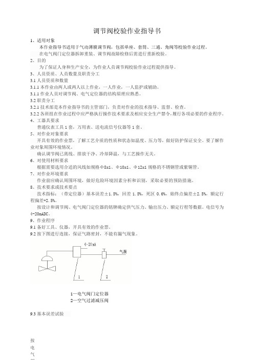
9.2按下图进行连接,保证气路密封,不能有漏气现象。
1—电气阀门定位器2—空气过滤减压阀9.3基本误差试验按电气阀门定位器标准信号范围(4-20mA),分四等份,将输入信号平稳地按增大或减小方向输入定位器,测量各点所对应的行程值,并按公式(1)计算实际“信号-行程”关系与理论关系之间的各点误差,其最大值即为基本误差。
汽轮机WOODWARD505操作指南
操作指南简介键盘和显示器505E的服务面板由调速器前面板上的键盘和LED(发光二极管)显示器组成。
LED显示器可以显示2行(每行24个字符),用来显示运行参数和故障检测参数,使用的语言是简单英文。
通过505E前面板上的30个按键可以实现全部的控制操作。
操作控制透平时无需另外的控制面板,所有的透平控制功能都能通过505E的前面板执行。
下面将对每个键的功能作一说明。
具体有些说明请参见505E说明书操作流程图(第5章),里面详细的介绍了每个功能键下的菜单,如何操作,请仔细阅读。
SCROLL (翻页键): 键盘中央的大菱形键,菱形的四个角上各标有一个箭头。
◄,►(左、右翻动):在编程或运行模式下使功能块显示左、右移动。
▲,▼(上、下翻动):在编程或运行模式下使功能块显示上、下移动。
SELECT(选择键): 用于505E显示器上行或下行变量的控制选择。
符号@用于指示哪一行(变量)能通过ADJ键来进行调整。
只有当上、下均有可调整变量(动态、阀门标定模式)时,才会使用SELECT键和@符号来决定哪一行的变量可被调整。
当显示器上只有一个可调整参数时,SELECT键不能改变@符号的位置。
ADJ (调整键): 在运行模式下,▲增大可调参数,▼减小可调参数。
PRGM (编程键): 当调速器处于停机状态时,用该键可进入编程模式。
当调速器处于运行模式时,用该键可进入程序查看模式。
在程序查看模式下,程序只能查看,不能修改。
RUN(运行键): 当机组准备就绪后,按RUN键发出一个透平运行或启动的命令给505E。
STOP(停止键): 一旦给予确认,触发透平控制停机(运行模式下)。
通过服务模式设定(在‘键选项’下)可以禁用STOP命令。
RESET(复位键):用于复位/清除运行模式下报警和停机。
在停机后按该键,还能使调速器返回到((Controlling Parameter / Push Run or Prgm)状态。
0/NO: 输入0/NO或退出。
woodward电子调速器调试教程要点

电子调速器调试教程一、参数输入步骤1.第一步:确认转速传感器、执行器、控制器各处接头的可靠连接。
并按照应用图纸检查电路连接;将调试工具与电脑、APECS控制器可靠连接。
连接示意图如下:速度传感器的作用是测量发动机的速度,其作用非常重要。
如果其工作不正常,将导致系统根本无法正常工作。
对螺距为1mm的传感器,转动传感器直到它接触齿轮外径,再将它旋出95-130度以得到一个0.38-0.51mm的间隙。
传感器安装必须按正确的方法以保证合适的间隙第二步:打开汽车电源但不启动发动机,然后闭合电调开关观察控制器指示灯应以每秒一次的频率闪烁。
第三步:双击桌面ACT快捷方式第四步:进入如下界面第五步:将下图相应方框选中第六步:点击下一步第七步:输入发动机的缸数和飞轮齿数第八步:选中本系统所使用的转速模式第九步:在下图方框中输入系统所需额定转速第十步:点击下一步第十一步:将所设参数载入控制器第十二步:参数设置完成第十一步:进入调试界面,输入相应的经验P、I、D值P I D调节方法:厂家的原始设置是比较好的开始调整的组合,调试时,先调P,然后是I,最后是D。
之后再调P和I。
如果需要,重复此步骤。
●P(比例增益):用来改善响应时间。
调试中应在维持系统稳定的前提下尽量采用大的比例增益。
调试P的方法是增加P直到速度出现振荡,然后减小P直到振荡停止。
如果系统没有产生振荡,碰一下执行器的连接杆使之产生振荡,然后减小P直到振荡消失。
●I(积分增益):用来消除稳态错误。
调试方法是增加I直到速度产生波动,然后降低I直到振动停止。
如果系统没有产生振荡,碰一下执行器的连接杆使之产生振荡,然后减小P直到振荡消失。
●D(微分增益):用来提高稳定性。
增加D直到当突加突减负载会引起系统轻微振荡为止。
注意:每添入或修改一个参数都要按回车确认才能存入控制器,起作用。
二、调试软件常用菜单说明波形图显示窗口设置其中常用到的几个参数为:PLOT1里的engine_rpm发动机实际转速;PLOT2里的n_desired设定转速值,tpc_dutycycle为占空比信号,如果选择此参数则相应下面的数值范围最大设1最小设0,因为占空比为一百分数;三、常见故障诊断常规检查:请按下述步骤对APECS电子调速器作常规检查。
调速器作业指导书

调速器作业指导书1目的对船用调速器的修理做技术要求。
2范围本标准规定了船用调速器的修理技术要求及修理后的试验要求。
3职责3.1技术部门负责作业指导书下发,工艺指导。
3.2检验部门负责检验合格。
3.3施工人员严格按照流程施工。
4工作程序4.1调速器机上拆下时的注意事项4.1.1调速器从机上拆下之前,作业人员应当向船方了解修理的原因、工作状况及其过去所发生的一些不正常的现象(例如:有没有波动,起动困难,加速困难等情况)。
4.1.2进入机舱后确定控制空气是否已关、吊机是否可用及电源开关位置(注:在使用时发生意外可立刻将电源关上以确保安全)。
4.1.3在拆出调速器前,先记录调速器的设计号(即D/N),伺服器与调整器之间的油管做记号,记录调速器的指示在零的位置与主油排的指示位置或高压油泵的指示位置。
4.1.4在调速器从机上拆下时,应注意其原来的安装连接是否正确,如油排连接是否正确、灵活、连杆连接部位间隙是否过大、调速器输出轴手柄第几孔与油排连接。
拆下调速器伺服马达连接线时要做好笔录。
机座传动齿轮、齿孔是否正常,如有异常应及时通知船方。
4.1.5拆除调速器底座螺丝及连杆(主机拆除所有管子连接)。
4.1.6调速器拆下后需检查传动所有连接部位及燃油泵、齿条方面等是否原先就存在问题。
如有发现问题需及时与船方沟通并以书面形式告知经营部。
4.1.7检查完后把调速器底座螺丝旋回原处并用纸板或回丝布将底座罩住,以防止垃圾进入(主机将所有管路接头部位用回丝布包好)。
4.2调速器修理过程中的注意事项:1.1.1.1调速器进厂后首先做好登记工作,如调速器的所属单位(船名)、设计号、序号、速降、补偿指针刻度、针阀开度、进厂日期、工程编号等,还要做好调速器输出轴与柄、调速器与外部管接头的记号。
1.1.2.速器解体前(除UG8D、SGsPSG、D.K等型号外),需要上试验台测试。
如果原始状态很差或原始数据超出WoodWard标准参数范围,必须通过经营部与客户联系,以妥善处理。
- 1、下载文档前请自行甄别文档内容的完整性,平台不提供额外的编辑、内容补充、找答案等附加服务。
- 2、"仅部分预览"的文档,不可在线预览部分如存在完整性等问题,可反馈申请退款(可完整预览的文档不适用该条件!)。
- 3、如文档侵犯您的权益,请联系客服反馈,我们会尽快为您处理(人工客服工作时间:9:00-18:30)。
WOODWARD调速器参数修改及调速阀校验作业指导书
WOODWARD调速器参数修改及调速阀回路校验作业指导书
1 适用范围
适用于WOODWARD调速器505D、505E。
2 目的
熟悉WOODWARD调速器的组态方法,通晓参数所包含的意义并能够修改参数;校验WOODWARD调速阀的阀门特性,使其精确工作。
3 人员资格、人员数量及职责分工
3.1人员资格和数量
3.1.1熟悉WOODWARD调速器的接线、调速器的组态方法、调速阀供油系统,会正确使用WOODWARD的操作界面,能正确修改参数。
3.1.2作业前应协同分工,一般应有2-3人进行,2人操作,另外人员配合。
3.2 职责分工
3.2.1 车间技术组是本作业指导书的主管部门,负责对作业的技术指导、监督、检查。
3.2.2 各班组在作业过程中应严格执行操作技术要求及相应安全生产禁令。
4 工器具准备及要求
4.1作业前准备一份空白的505调速器组态菜单。
4.2仪表常用工具一套。
4.3信号发生器一台、万用表一台、对讲机一对。
4.4干净抹布几块。
5作业前检查项目
5.1检查对讲机通话是否正常、信号发生器工作是否正常、万用表的电流档是否完好。
5.2检查需要修改的参数是否在所选择的菜单里,参数值是否正确同时对系统的原参数进行记录以备核对。
5.3检查WOODWARD调速器工作正常、无系统报警。
5.4检查WOODWARD调速阀供油压力正常。
WOODWARD调速器参数修改及调速阀回路校验作业指导书
5.5检查并确认T&T阀中TRIP阀在全关位置。
6技术要点
6.1了解WOODWARD调速器的接线。
6.2了解WOODWARD调速器的组态方法。
6.3了解WOODWARD调速器的操作界面。
6.4了解WOODWARD调速阀的供油系统
6.5了解WOODWARD调速器的人机界面
7使用具体作业步骤
7.1确认T&T阀中的TRIP阀处于全关位置(机组停车)
7.2在WOODWARD调速器上按PROGRAM,屏幕上会要求输入PASSWORD,输入密码后就进入组态界面。
7.2.1WOODWARD505调速器的组态菜单共有十三个大菜单,分别为:
1、TURBINE START(透平启动)
主要包含:启动方式、启动时速度斜率、IDLE设定点、冷启动与热启动的时间设定、冷启动与热启动的斜率设定、IDLE延迟时间、是否使用外部跳闸以及是否使用复位来清除跳闸输出等等。
2、速度设定
包含转子旋转一圈的脉冲数、齿轮比、速度探头故障判断、离线和在线的P、I、D 参数的设定等。
3、速度设定点
包含超速测试限位值、超速跳闸值、可控制速度范围、设定点斜率、临界转速设定等。
4、操作参数
包含是否使用TIE\GEN断路器断开跳闸、最大功率设定、额定速度设定、使用就地\远程控制等。
5、驱动组态
WOODWARD调速器参数修改及调速阀回路校验作业指导书
包含输出电流范围、是否反向输出、死区设定、一路或两路输出等。
6、模拟输入
包含1-6路输入参数的种类、量程。
7、节点输入
包含1-12路节点信号类型。
8、功能键
对F3和F4键的定义。
9、辅助控制
包含是否使用辅助控制、辅助输入信号丢失是否联锁、是否使用功率输入、是否反转、量程、初始值、辅助控制P、I、D设定等。
10、串级控制
包含是否使用串级控制、是否反转、串级设定点量程、斜率、是否跟踪、速度设定高低限值、串级控制PID设定以及单位等。
11、模拟输出
包含1-6个模拟输出回路的组态。
12、继电器
包含1-6个继电器回路的组态,如信号类型、动作值等。
13、通讯
包含调速器与外方设备的通讯协议组态。
7.3组态完成后按CLEAR键两次调速器即可从编程状态回到初始画面。
7.4在WOODWARD调速器上调整输出信号对调速阀进行校验
7.4.1将WOODWARD调速器的外部紧急停车信号用短接线短接
7.4.2在调速器面板上按RESET
7.4.3在调速器面板上按EMERGENCY SHUTDOWN
7.4.4在调速器面板上按ACT,然后通过按SCROLL DOWN键直到出现STROKE ACTUATORS-DSBLED,STEAM MUST BE OFF,再按YES,随后出现STROKE TO MIN (I)
WOODWARD调速器参数修改及调速阀回路校验作业指导书
CURR ADJUST,此时通过ADJ键可以调整调速器的电流输出(20-160MA).
7.4.5当调速阀动作存在问题时,
7.4.5.1检查调速器输出的电流信号是否正常
7.4.5.2检查调速阀的供油压力是否正常
7.4.5.3检查调速阀连接的连杆是否松动
注意:1、调速阀的全关位置非常重要,在满足生产的前提下,行程可放次要位置。
2、以上检查均正常时,就需要将调速阀拆下送有资质的部门维修。
8安全及维护保养要求
8.1安全要求
8.1.1作业人员在作业前要确认TRIP阀处于全关位置,并要得到工艺同意。
8.1.2作业中不可随意更改其他参数。
8.1.3作业后将组态菜单进行认真记录完善并做好存档。
8.1.4作业时机组必须处于停车状态。
8.1.5作业中不可随意拆下调速阀的油管线。
8.1.6作业时严禁调速器电流输出信号线接地或短接。
8.2设备日常维护和保养
8.2.1定期检查调速器有无系统报警。
8.2.2定期检查调速阀油路的密封性、压力是否正常。
8.2.3定期检查调速阀内电流接线端子是否牢固。
