百图富BY系列三脚架说明书
富士牌照相机使用说明书

富士牌照相机使用说明书各零件名称(P10)1、快门键( p22)2、开关(电源)键 (p18)3、闪光灯 (30)4、自动拍照指示灯 (p32)5、镜头∕镜头盖 (P46)6、麦克风 (p46)7、扬声器(p47)8、液晶显示屏 (p11)9、DISP(照片显示 )∕BACK(退回 )键(静态拍照)键(p31) 10、指示灯11、 W(广角变焦)键()12、 T(摄远变焦 )键()13、USB 多级连结器插孔()14、(放像 )键(p39)15、吊带挂扣(p2)16、电池盖( p12)17、三脚架用螺丝孔18、电池插入部( p12)19、电池拆卸按纽( p12)20、储存器插孔( p15)翻开∕封闭电源(p18)按 ON∕OFF(电源 )键,电源翻开;再按一次,电源封闭。
※经过重放模式翻开电源:按住重放键约 1 秒,电源翻开;重放过程中,按重放键,电源封闭。
设置使用的语言和时间(p19)购置相机后,第一次翻开电源时,使用的语言和时间没有设置。
可依据以下次序选择使用的语言并设置时间。
1、翻开电源,语言设置画面被显示出来。
2、选择使用的语言。
3、按 MENU∕OK 键,语言被设置,时间设置画面显示出来。
4、经过选择设置的项目(年、月、日、时、分),经过上∕下三角(▲▼)变更设置的项目(年、月、日、时、分)。
5、选择年、月、日。
6、从年,月,日、月∕日∕年、日,月,年选择日期的摆列次序。
7、按 MENU∕OK 键,语言和时间设置达成,能够开始拍照。
※ 校订:想要从头设置语言和时间时,能够经过设置菜单(セットアップメニュー)进行再设置。
注:拿出电池并经过长久保留以后,设置的时间会自动除去,并经过确认画面显示出来。
装入电池约 2 小时后,即便再拿出,设置的时间也能够保持大概 24 小时。
基本拍照和重放( p20)■ (自动)拍照这里介绍拍照的基本操作流程。
翻开相机电源( p20)1、按 ON∕OFF键,翻开相机电源。
带你解锁脚架新姿势!曼富图190go!M系列三脚架解析

带你解锁脚架新姿势!曼富图190go!M系列三脚架解析曼富图(Manfrotto)是知名的意大利专业摄影器材品牌,曼富图经典的190系列更是引领三脚架潮流的知名产品系列,相信大家一定都不陌生。
全新190go!M系列近期,曼富图全新推出190go!M系列三脚架,该系列三脚架是190go!系列的升级产品。
190go!M采用M-Lock旋锁机制,搭配XPRO系列云台和全新两种材质的三脚架脚管,可以进行非常快速和精确的设置,是集便携性和专业性于一身的三脚架产品。
装配了MHXPRO-BHQ2三维云台的190 go!M碳纤维三脚架套装两种材料两种云台满足多种不同需求我们本次试用的产品是装配了MHXPRO-BHQ2三维云台的190 go!M碳纤维三脚架套装。
除了我们试用的这款套装之外,190 go!M系列三脚架根据脚管材质和云台型号的不同,还有几种套装可供选择。
全新190 go! M系列拥有铝合金、碳纤维两种脚管材质。
其中铝合金产品采用了增强的D形铝合金材料,通过提升扭转强度提升了三脚架的稳定性,这款产品偏重于性价比。
而碳纤维产品则使用了升级的碳纤维材料,比以往的碳纤维材料更轻,同时具备更佳的稳定性。
因而碳纤维版本的190 go! M三脚架也成为曼富图专业三脚架产品序列中有史以来最轻盈的产品。
三脚架搭配的云台则有XPRO三维云台(型号为MHXPRO-3W)和XPRO球型云台(型号为MHXPRO-BHQ2)两种选择。
XPRO是曼富图的高端云台产品系列,在本次升级中,XPRO云台的加入让三脚架如虎添翼:三维云台能够实现精确的构图操作,球型云台则能够实现快速平滑的构图。
什么是M-Lock旋锁机制?接下来,我们要为大家介绍该系列产品最大的亮点——M-Lock 旋锁机制。
它是曼富图新推出的新型脚管锁止机制。
众所周知,三脚架脚管锁主要有搭扣和旋锁两种类型,而190go!M系列的M-lock旋锁能够集二者之所长:只要将旋锁旋转90°(1/4圈)就可以将两节脚管分离开来,锁定的三节脚管在短短几十秒的时间内就能完全打开,完成脚架的设置。
锐迪安 三脚架云台 产品手册说明书

Radian TRIPOD BALL HEAD23Attaching/Removing the Radian ™ Ball HeadTo mount the ball head to the tripod:1. Lift the Quick-Release Locking Latch on the tripod.2. Press and hold the Platform Release Button andfully seat ball head into the tripod. Once seated, the ball head can be oriented in any direction. 3. Rotate the Quick-Release Locking Latch down tothe locked position.4. To remove the ball head, follow these steps inreverse order.NOTE: If needed, the locking latch can be repositioned by shifting the latch to the left and rotating the latch up/down to reposition.Quick-Release PlateQuick-ReleaseBubble LevelDrag Tension KnobPress the Quick-Release Button on the tripod to seat the ball head.Quick-Release Locking LatchBase Panning KnobCounterweight HookTo help stabilize the tripod in windy conditions, hang a weight from the Counterweight Hook.Radian TRIPOD BALL HEAD45Tilt ActionThe ball head’s tilt can be adjusted by unlocking the ball head. This allows you to position your optic at the desired angle. For extreme angle, or full vertical orientation, rotate the head into one of the two cutaways.• To unlock the ball head, rotate the Ball Locking Knob counter-clockwise until the head moves freely. Adjust to your desired position and lock the ball head.• To lock the ball head, rotate the Ball Locking Knob clockwise until you feel tension on the knob.Panning ActionThe Radian ™ Ball Head can be adjusted to allow you to pan across a scene without adjusting the ball head’s angle. This is particularly helpful while glassing wildlife moving across a field, maintaining a flexible shooting position for your mounted rifle.To use the Panning Base Knob:• To unlock the panning base, twist the Panning Base Knob counter-clockwise.• To lock the panning base, twist the Panning Base Knob clockwise. You may also adjust the drag of the panning base by tightening the Panning Base Knob, but not locking it down completely. This will allow you to have more control for smoother panning across a scene.Adjusting Drag TensionThe drag tension can be adjusted on the Radian ™ Ball Head for when the head is in the unlocked position, allowing you to pan and tilt the ball head. This is helpful when viewing fast-paced action scenes. To adjust the drag tension, unlock the ball head by rotating the Ball Locking Knobcounter-clockwise. Turn the Drag Tension Knob clockwise to increase the drag tension, or counter-clockwise to decrease the drag tension.NOTE: Once the drag tension is set, it will stay at this tension no matter how much the Ball Locking Knob is loosened.Rotate the Ball Locking Knob to adjust position or lock in place.Adjust the Drag Tension Knob.Rotate the Panning Base Knob to pan or lock in place.Radian TRIPOD BALL HEAD67Attaching Optics to Ball HeadThe Radian ™ Ball Head uses Arca-Swiss style quick-release plates. To mount your optic to the tripod:1. Twist the Quick-Release Locking Knob counter-clockwise to remove the Quick-Release Plate.2. Attach the plate to your optic. Be sure to tighten the Mount Bolt from the bottom side of theplate and flip the D-ring so it lies flat.3. Place the Quick-Release Plate back into the tripod head and turn the Quick-Release LockingKnob clockwise to securely lock the plate in the head. NOTE: To mount binoculars to the tripod, a binocular adapter is required. Purchase Vortex ® binocular adapters from your local dealers.NOTE: Some optics are designed to be Arca-Swiss compatible and can be mounted to the tripod head without the need for plates.TIP: Purchase additional quick-release plates for your optics so it is easy for you to switch equipment.Quick-Release Plate and Mount BoltQuick-Release Locking KnobVIP WARRANTYOUR UNCONDITIONAL PROMISE TO YOU.We promise to repair or replace the product. Absolutely free.Unlimited UnconditionalLifetime Warranty************************•800-426-0048Note: The VIP Warranty does not cover loss, theft, deliberate damage, or cosmetic damagenot affecting product performance.For additional information, and the most up-to-dateproduct manuals, visit 。
伯克莱摄影三脚架系列产品介绍说明书
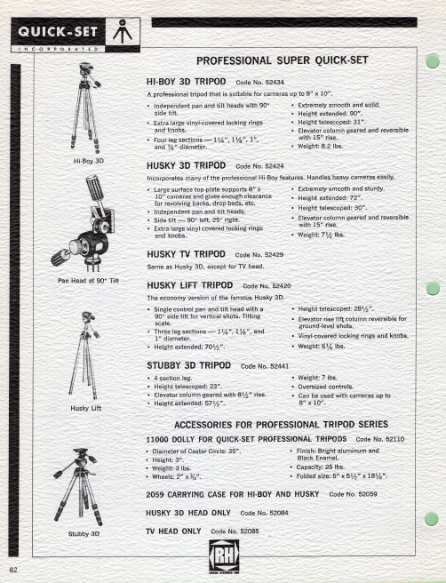
HUSKY 3D TRIPOD Code No. 52424
-
Incorporates many of the professional Hi-Boy features. Handles heavy cameras easily.
• Large surface top plate supports 8" x 10" came~as and gives enough clearance for revolving backs, drop-beds, etc.
Auto·Pro Fingertip Release
Travelite 2L
AUTO-PRO TRIPOD Code No. 52412
New "Auto·Lok" self·locking levers for completely automatic leg extension and elevator locking! No bush ings or screws to loosen or tighten ... can't slip! Sets up and folds down
Model 5000
2
Model 6000
3
54 1h"
59"
PROFESSIONAL Husky Lift Husky 3-D Hi-Boy 3-D Stubby 3-D
SUPER QUICK-SET
3
70 1h"
3
72"
4
90"
4
57 1h"
TELESCOPED LENGTH
坠落救援用三脚架
整性。任何曾在实际发生的坠落事故中使用过的个人防护装备都应暂停使用。任何时候都不 要擅自对您的任何个人防护装备进行修改或维修;只有制造商或授权维修中心才有资格进行 有关的维修工作。这些使用说明须与有关的个人防护装备存放在一起。
三角架符合en795类产品标准安装将三角架支撑起来即把其三条支撑腿撑开直至位于每条支撑腿顶端的夹扣锁孔装置在相应的位置上锁定如果不调整锁孔装置应无法将各条支撑腿收拢
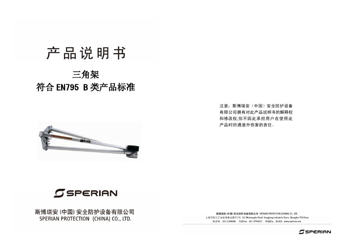
三角架 符合 EN795 B 类产品标准
注意:斯博瑞安(中国)安全防护设备 有限公司拥有对此产品说明书的解释权 和修改权,但不因此承担用户在使用此 产品时所遇意外伤害的责任。
注意: 您所购买的产品为个人防护产品(PPE),感谢您对本公司产品的信任! 为了使该产品的使用达到您的要求,请在每次使用之前遵照本手册中的使用说明执行。
如对本手册所述的使用说明置之不理,可能会造成一些严重的影响。我们建议您经常重新阅 读这些使用说明。此外,如果以本使用手册所述内容之外的其它方法使用、保存或维护本产 品,供应商和代理商拒绝承担一切责任!如果购买者不是最终用户,务必将这些使用说明转 交给最终用户!
常旋转(在使用时) 。
滑轮
使用:取下连接滑轮的安全钩,以便让缆绳从沟漕中穿过。然后将安全钩重新装好,并 确定将安全钩已锁紧。
救援绞盘 符合 EN1496 B 类产品标准
安装 利用所提供的两个插销将绞盘固定在三角架或 Miller Potex 悬臂上,然后用插销将每一插
销孔锁定。确定绞盘周围留有足够的空隙,并且没有可能防碍或阻止绞盘正常操作的障碍物。 位于缆绳一端的一个自动抓钩可以与符合 EN361 标准的坠落防护全身安全带、符合
GlideGear G2H 100 摄影机支架说明书

Fig. 2
3 Screw the Rail Caps (D) at the end of each Vertical Rails (C) as shown in Fig. 3.
4 You can now mount your camera onto the Camera Plate (E).
For more information please visit our website:
For more information please visit our website:
Using the G2H 100 with a vest and arm system
PLEASE NOTE that the G2H 100 needs to be used in combination with a Vest and Arm system and is compatible with any vest and arm system with a pin diameter smaller than 7/8” or 22.5mm To use the G2H 100 with your vest and arm system, simply slide the arm’s pin inside the G2H 100 handle (F) as shown iments
Move the Main Frame (A) along the Vertical Rails (C) to balance
the camera’s tilt axis
Lock Main Frame (A) into position using the thumb-
screws
Move the Camera Plate (E) along the Camera Rails (B) to balance the camera’s roll axis
百诺经典板扣系列三脚架使用说明书
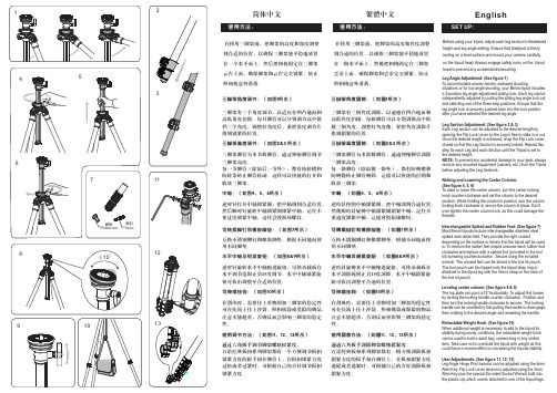
简体中文在使用三脚架前,把脚架的高度和角度调整到合适的位置,以确保三脚架能平稳地放置在一个水平面上,然后把相机固定在三脚架云台上面,确保脚架和云台完全锁紧,防止照相机意外滑落。
三脚架有三个角度调节,以适应在凹凸地面和高低角度拍摄。
每只脚管可以分别调节高中低档三个角度,调整好角度后,要把角度调节片推到锁紧的位置。
三脚架脚管为多节数脚管,通过伸缩脚管调节三脚架高度。
每一节脚管(除最后一节外),都有防转槽和防转条防止脚管转动。
这样可以快捷的打开和收放三脚架。
逆时针拧开中轴锁紧圈,把中轴调到合适位置,然后顺时针旋转中轴锁紧圈锁紧中轴,记住不要过度锁紧中轴,这样会毁损坏螺纹。
互换不锈钢脚钉和橡胶脚垫。
根据不同地面使用不同脚垫。
逆时针旋转水平中轴缩进旋钮,可使承载板在水平调节范围正负15度调节。
水平中轴锁紧旋钮可拔出调整至合适的位置。
在刮风时,需要挂上重物增加三脚架的稳定性可在挂钩上挂上沙袋、照相机袋或类似的物品。
注意不能超重,否则反而会影响三脚架的稳定性。
百诺经典板扣系列脚架都有一个方便调节扳扣锁紧力度的扳手扣在脚管上,在扳扣锁紧力度过松或者过紧时,可根据自己的喜好调节扳扣锁紧力度。
通过六角扳手调节脚架螺丝松紧度。
三脚架角度调节:(如图1所示)三脚架高度调节:(如图2&3 所示)中轴:(如图4、5、6所示)水平中轴及锁紧旋钮:(如图8&9所示) 使用调节方法:(如图11、12、13所示)可转换脚钉和橡胶脚垫:(如图7所示)可伸缩挂钩:(如图10所示)English繁体中文Before using your tripod, adjust each leg section to thedesired height and leg angle setting. Ensure that thetripod is firmly resting on a level surface and mount your camera carefully on the tripod head. Always engage safety locks on the tripod head to prevent any accidental dismounting.Leg Angle Adjustment: (See figure 1)To accommodate uneven terrain, awkward shootingsituations or for low angle shooting, your Benro tripod includes a 3-position leg angle adjustment sliding lock. Each leg can be independently adjusted by pulling the sliding leg angle lock out and selecting one of the three step positions. Ensure that the leg angle lock is securely pushed back into the lock position after you have selected the desired leg angle.Leg Section Adjustment: (See figure 2 & 3)Each Leg section can be adjusted to the desired length by opening the Flip Lock Lever so the Leg is free to slide in or out. Once the desired length is achieved, snap the Flip Lock Lever closed so that the Leg Section is securely locked. Repeat this step for each Leg and each Section until the Tripod is set to the desired height.NOTE: To prevent any accidental damage to your gear, always remove any mounted equipment (camera, etc.) from the Tripod before adjusting the Leg Sections.Raising and Lowering the Center Column: (See figure 4, 5, 6)To raise or lower the center column, turn the center locking knob counter-clockwise and set the column to the desired position. While holding the column in position, turn the column locking knob clockwise to secure the column in place. Don't over tighten the center column lock, as this could damage the threads.Interchangeable Spiked and Rubber Feet: (See figure 7)Most Benro tripods include interchangeable stainless steel spiked and rubber feet. They provide the right contactdepending on the surface or terrain that the tripod will be used in. To remove the rubber feet simple unscrew each rubber foot clockwise and replace with a spiked foot (provided in the tool kit) screwing counterclockwise. Secure using the included wrench. The unused feet can be stored in the tool kit pouch. The tool pouch can be clipped onto the tripod strap ring or attached to the tripod leg with the Velcro strap on the back of the tool kit pouch.Leveling center column: (See figure 8 & 9)The top plate can pivot ±15°horizontally. To adjust first loosen by turning the locking handle counter clockwise. Position and then turn the locking handle clockwise to secure. The locking handle can be oriented by first pulling the handle to disengage, then rotating to the desired angle and reseating the handle.Retractable Weight Hook: (See figure 10)When additional weight is necessary to add to the tripod for stability during windy conditions, the retractable weight hook can be used to hold a sand bag, camera bag or any similar item. Take care not to overload the tripod with weight as this could have a reverse effect on increasing the tripods er Adjustments: (See figure 11, 12, 13)Leg Angle Hinge Pivot tension can be adjusted using the 4mm Allen Key. Flip Lock Lever tension is adjusted using the 3mm Allen Key plus the special Six-sided Socket Wrench built into the plastic clip which comes attached to one of the tripod legs.在使用三脚架前,把脚架的高度和角度调整到合适的位置,以确保三脚架能平稳地放置在一个水平面上,然后把相机固定在三脚架云台上面,确保脚架和云台完全锁紧,防止照相机意外滑落。
marsace MT1542说明书
marsace MT1542说明书
xxx采用了等同于普通三脚架的脚管以及中轴设计,并且具有3节脚管可伸缩、3档脚管张角可调节的设计,使得M-4C在爬楼摄影时拥有不输一般三脚架的稳定性。
同时,xxx采用了xx结构的快装板夹座,可以兼容市面上大部分的快装板,全景云台的采用使得我们可以方便地进行全景接片。
三脚架定位需要注意的几点:
1、利用三脚架的升降功能在使用前取出三脚架展开后将摇杆旋转至工作高度,(工作高度等于身高减掉30公分)取下云台的快装版将快装版上的。
2、螺丝锁在相机的底部。
把相机装和快装版装在云台上,按要拍照的镜头调整工作高度,这时就可以用摇杆来调整高度。
3、在展开每支脚管时务必把每一支脚管全部拉打开至最大限度为止,并全部展开三支脚管。
因为在操作相机时,如果脚管没有拉到尽头存在将板。
4、扣固定好,脚管关节部位会很容易出现松动的情况,三支脚管也必须展开到最大限度,固定在地面的面积已大得足够,因此三脚架也不易移动。
5、将三脚架的其中一支脚调到镜头的正下方进行拍摄,另外两只脚管面向拍摄者的方向这样拍照的时候才不会碰撞到脚架。
6、检查固定座,看固定座是否固定完好,若没有固定完好,则必须再次固定。
7、找出水平线,找出水平线的目的在于在使用时方便核对三角架是否平稳,以保证使用的效果。
гомдустру roduction EFPAU TEST NO说明书
感谢您购买 产品!请仔细阅读本手册,它将帮助你妥善设置并运行您的系统,使其发挥卓越的性能。
并保留这些说明以供日后参照。
警告:为了降低火灾与电击的风险,请不要将产品暴露在雨中或潮湿环境中。
警告:为了降低电击的风险,非专业人士请勿擅自拆卸该系统。
仅供专业人士操作。
等边三角形中的闪电标记,用以警示用户该部件为非绝缘体,系统内部存在着电压危险,电压。
可能足以引起触电。
可能足以引起触电如系统标有带惊叹号的等边三角形,则是为提示用户严格遵守本用户指南中的操作与维护规定。
注意:请勿对系统或附件作擅自的改装。
未经授权擅自改装将造成安全隐患。
警告:燃不得将明火源(如点的蜡烛)放在器材上面。
1. 请先阅读本说明。
2. 保留这些说明以供日后参照。
3. 注意所有警告信息。
4. 遵守各项操作指示。
5. 不要在雨水中或潮湿环境中使用本产品。
6. 不要将产品靠近热源安装,例如暖气管、加热器、火炉或其它能产生热量的装置(包括功放机 )。
7. 不要破坏极性或接地插头的安全性设置。
如果提供的插头不能插入插座,则应当请专业人员更换插座。
8. 保护好电源线和信号线,不要在上面踩踏或拧在一起(尤其是插头插座及穿出机体以外的部分 )。
9. 使用厂商规定及符合当地安全标准的附件。
10.雷电或长时间不使用时请断电以防止损坏产品。
12. 不要让物体或液体落入产品内——它们可能引起火灾或触电。
13. 请注意产品外罩上的相关安全标志。
. 仅与厂商指定或与电器一同售出的推车、架子、三脚架、支架或桌子一起使用。
推动小车/电器时,应谨防翻倒。
11注意事项产品的安装调试须由专业人士操作。
在使用非本厂规定的吊装件时,要保证结构的强度并符合当地的安全规范。
警告:1扬声器及扬声器系统的产品有限保修期为自正式购买日起的3年。
由于用户不合理的应用而导致音圈烧毁或纸盆损坏等故障,不包含于产品保修项目。
产品吊附件(包括音箱装配五金件和吊挂配件)的有限保修期为自正式购买日起的1年。
BH-40电子球头与三脚架配件说明书
**Visit our website to see a ballhead video tutorial.
® , ™, © 2014 Really Right Stuff, Inc. All rights reserved.
3
8
4
2
1 5 6
7
KEY FEATURES
1. Pan Lock Knob — Our exclusive drum and band panning brake
Using the Drop Notch
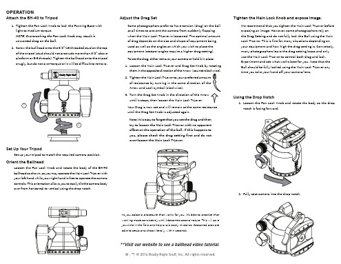
1. Loosen the Pan Lock Knob and rotate the body so the drop notch is facing forward.
2. Fully seat camera into the drop notch.
As you adopt a procedure that works for you, it’s best to practice that working mode consistently until it becomes second nature. This will save you time in the field and help avoid costly mistakes. Seasoned pros are able to setup and shoot literally within seconds.
MTS-SP100 Renogy 杆架安装系统说明书
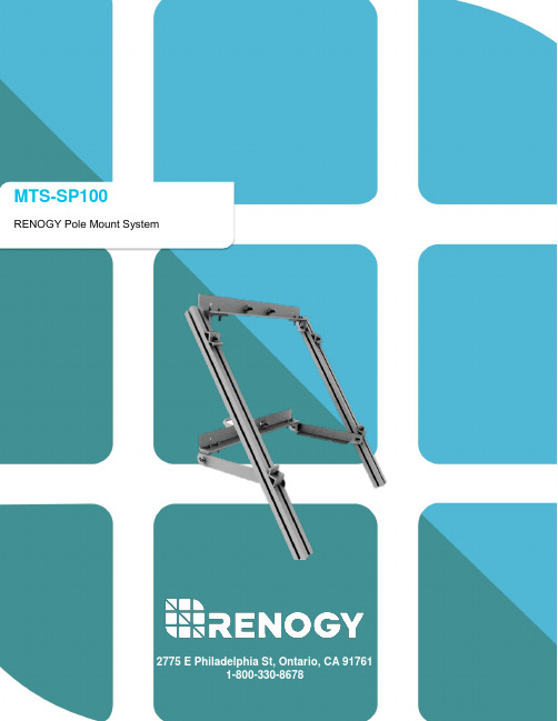
MTS-SP100 RENOGY Pole Mount SystemImportant Safety InstructionsPlease save these instructions.This manual contains important safety, installation, and operating instructions for the Renogy Pole Mount hardware system. The following symbols are used throughout the manual to indicate potentially dangerous conditions or important safety information.WARNING: Indicates a potentially dangerous condition. Use extreme caution when performing this task.CAUTION: Indicates a critical procedure for safe and proper operation of the system. NOTE: Indicates a procedure or function that is important to the safe and proper operation of the system.General Safety Information•Read all of the instructions and cautions in the manual before beginning the installation.•Do NOT attach solar panel to pole mount until mount is securely fit, and pole base has been secured.•Chance to strip nuts and bolts exists.•Multiple people for installation is suggested.•Do NOT substitute parts from other manufacture ring sources, doing so may void the warranty and/or result in an unstable system•This system is NOT possessing any compliance with residential structural codes and should not be used in place of a system that is, if required by local regulations Installer Responsibilities•Installation compliance with any applicable codes which are in force at the installation site •Installation compliance and compatibility with all system components and the environment including but not limited to roofing, system components, etc.•Verification that all project information is accurateWARNING: This equipment should be installed, adjusted, and serviced by qualified electrical maintenance personnel familiar with the construction and operation of the equipment and the hazards involved. Failure to observe this precaution may result in bodily injury. Protective gloves and safety glasses should be worn during installation.Table of ContentsGeneral Information (4)Identification of Parts (5)Installation (8)Fasten L-Channels to L-Brackets (9)Slide U-Bolt through back face of L-Channel (9)Attach Support Arm to bottom L-Brackets (10)Fasten T-Slotted Brackets to top L-Channel using the L-Brackets (10)Fasten the bottom of the T-Slotted Bracket to Support Arm (11)Slide panel onto brackets and fasten with end lamps (11)Pole Mount Dimensions (13)Compatibility (15)General InformationThe Renogy Pole Mount System is designed for off-grid applications, when mounting to a roof is not ideal. It will support off-grid systems, and Renogy 100W solar panel. The system comes complete with all fasteners to secure the system to the installation surface. This system makes the installation of small solar systems easy, affordable and quick.Key Features•5052-H32 aluminum construction•Stainless steel fasteners•High-tensile strength•Corrosion Free•Withstands 50 psf (125 mph wind loads)•Attractive brushed aluminum finish•Infinitely adjustable between 15-65 degrees•Precision hole positioning and alignment•Easy, rapid assembly•Well-illustrated instructions•Wind resistance of 120mphImageAttach Support Arm to bottom L-BracketsFigure 3Note: The reason for this is that depending on the angle that the T-Slotted brackets are fastened to the top L-Channel, you may need to adjust the bottom L-Channel so that it will be flush against the pole.Fasten T-Slotted Brackets to top L-Channel using the L-BracketsFigure 4(G)(H)(I)(K)(D)(K)(H)(F)(A)(I)CompatibilityRENOGY Solar Module Compatibility* RNG-10D INCOMPATIBLERNG-10D-SS INCOMPATIBLERNG-20D INCOMPATIBLERNG-30D INCOMPATIBLERNG-30D-SS INCOMPATIBLERNG-50D INCOMPATIBLERNG-50D-SS INCOMPATIBLERNG-80D-SS INCOMPATIBLERNG-100D COMPATIBLERNG-100D-S COMPATIBLERNG-100D-SS COMPATIBLERNG-100D-SSP COMPATIBLERNG-100MB COMPATIBLERNG-100D-R COMPATIBLERNG-160D-SS INCOMPATIBLERNG-300D INCOMPATIBLERNG-50P INCOMPATIBLERNG-100P COMPATIBLERNG-160P INCOMPATIBLERNG-270P INCOMPATIBLERNG-320P INCOMPATIBLE Renogy reserves the right to change the contents of this manual without notice.。
Festo标牌支架操作手册说明书
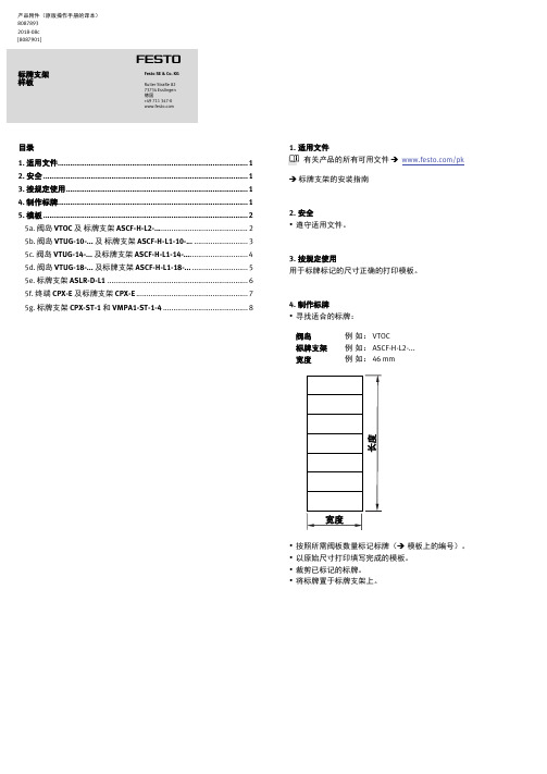
产品附件(原版操作手册的译本)80878932018-08c[8087901]†‡标牌支架样板Festo SE & Co. KG Ruiter Straße 82 73734 Esslingen德国+49 711 347-0目录1. 适用文件 (1)2. 安全 (1)3. 按规定使用 (1)4. 制作标牌 (1)5. 模板 (2)5a. 阀岛VTOC及标牌支架ASCF-H-L2- (2)5b. 阀岛VTUG-10-...及标牌支架ASCF-H-L1-10-... .. (3)5c. 阀岛VTUG-14-...及标牌支架ASCF-H-L1-14-. (4)5d. 阀岛VTUG-18-...及标牌支架ASCF-H-L1-18-... (5)5e. 标牌支架ASLR-D-L1 (6)5f. 终端CPX-E及标牌支架CPX-E (7)5g. 标牌支架CPX-ST-1和VMPA1-ST-1-4 ......................................... 81.适用文件有关产品的所有可用文件→/pk →标牌支架的安装指南2.安全∙遵守适用文件。
3.按规定使用用于标牌标记的尺寸正确的打印模板。
4.制作标牌∙寻找适合的标牌:阀岛例如: VTOC标牌支架例如: ASCF-H-L2-...宽度例如: 46 mm∙按照所需阀板数量标记标牌(→模板上的编号)。
∙以原始尺寸打印填写完成的模板。
∙裁剪已标记的标牌。
∙将标牌置于标牌支架上。
5. 模板5a.阀岛 VTOC及标牌支架 ASCF-H-L2-...宽度: 46 mm长度: 29.5 … 250 mm12 3 4 5 6 7 8 9 10 111213 14 15 16 17 18 19 20 21 22 23241 2 3 4 5 6 7 8 9 10 11 12 13 14 15 16 17 18 19 20 21 22 23 24宽度: 38mm长度: 37 ... 247 mm12 3 4 5 6 7 8 9 10 111213 14 15 16 17 18 19 20 21 22 23241 2 3 4 5 6 7 8 9 10 11 12 13 14 15 16 17 18 19 20 21 22 23 24宽度: 38 mm长度:53.5 … 373.5 mm1 112 2 23 3 34 4 45 5 56 6 67 7 78 8 89 9 910 10 1011 11 1112 12 1213 13 1314 14 1415 15 1516 16 1617 17 1718 18 1819 19 1920 20 2021 21 2122 22 2223 23 2324 24 24宽度: 38 mm长度:62.5 … 442.5 mm1 13 1 132 14 2 143 15 3 154 16 4 165 17 5 176 18 6 187 19 7 198 20 8 209 21 9 2110 22 10 2211 23 11 2312 24 12 241 2 3 4 5 6 7 8 9 10 11 1213 14 15 16 17 18 19 20 21 22 23 245e.标牌支架 ASLR-D-L1宽度: 17.5mm长度:8 … 192 mm1 12 23 34 45 56 67 78 89 910 1011 1112 1213 1314 1415 1516 1617 1718 1819 1920 2021 2122 2223 2324 245f.终端 CPX-E 及标牌支架CPX-E宽度:15.5 mm 长度:80 mm111112 2 2 2 2 333334 4 4 4 45 5 5 5 56 6 6 6 67 7 7 7 7888881 1 1 1 12 2 2 2 2 333334 4 4 4 45 5 5 5 56 6 6 6 67 7 7 7 7888881 1 1 1 12 2 2 2 2 333334 4 4 4 45 5 5 5 56 6 6 6 67 7 7 7 7888885g. 标牌支架 CPX-ST-1 和 VMPA1-ST-1-4宽度: 39.5 mm 长度: 9 mm。