DCH英文规格书
303540SpecificationForApproval英中文电池规格书
303540SpecificationForApproval英中文电池规格书SHENZHEN HHS ELECTRONICS CO.,LTD.SHENZHEN HHS ELECTRONICS CO.,LTD.SHENZHEN HHS ELECTRONICS CO.,LTD.SHENZHEN HHS ELECTRONICS CO.,LTD.SHENZHEN HHS ELECTRONICS CO.,LTD.SHENZHEN HHS ELECTRONICS CO.,LTD.SHENZHEN HHS ELECTRONICS CO.,LTD.6、Visual inspection/产品外观要求There shall be no such defect as scratch, flaw, crack and leakage, which may adversely affect commercial value of the cell.成品电池不可出现划伤、污迹、变形、褪色、漏液等不良现象。
7、The warranty period/保修期12 Month from the factory shipment.从出厂代码日起12个月保修。
8、 Storage 储存8.1 The Li-ion battery pack should be stored in a cool, dry and well-ventilated area, and should befar from the fire and the high temperature.锂电池需保存在阴凉,干燥,通风的环境中,避免接触火源与热源。
8.2 The battery should store in the product specification book stipulation temperature range, the beststorage temp. is 0 to 25℃. The best humidity is 60±25%.电池需按规格书规定温度范围进行储存,最佳储存温度0-25℃,最佳湿度为60±25%。
g5nb 英文规格书

g5nb 英文规格书G5NB English Specification BookThe G5NB English Specification Book provides a comprehensive overview of the specifications and features of the G5NB product. This article aims to provide an accurate description of the G5NB product and its key specifications, without including any web links or images.The G5NB product is a high-performance electronic device designed for various applications in the field of electrical engineering. It is renowned for its reliability, efficiency, and advanced features that meet the demands of modern industries.1. Electrical Specifications:The G5NB product operates within a specified voltage range of X volts to Y volts. It has a maximum current capacity of Z amperes, making it suitable for a wide range of electrical circuits. The product's power consumption is A watts, ensuring energy efficiency and cost-effectiveness.2. Mechanical Specifications:The G5NB product has a compact and robust design, with dimensions of L x W x H. It is made of high-quality materials, ensuring durability and longevity. The product's weight is B kilograms, making it easy to handle and install in various applications.3. Environmental Specifications:The G5NB product is designed to withstand challenging environmental conditions. It operates within a temperature range of C to D degrees Celsius, making it suitable for both indoor and outdoor applications. It also has a high resistance to dust, moisture, and vibrations, ensuring reliable performance in harsh environments.4. Features:The G5NB product offers a range of advanced features that enhance its functionality and usability. Some notable features include:4.1. Overload Protection: The product is equipped with built-in overload protection mechanisms, preventing damage from excessive electrical current.4.2. Short Circuit Protection: It includes short circuit protection to prevent damage caused by sudden electrical shorts.4.3. Thermal Protection: The G5NB product is designed with thermal protection to prevent overheating, ensuring safe and reliable operation.4.4. High Efficiency: It offers high efficiency in energy conversion, reducing power loss and maximizing performance.4.5. Easy Installation: The product is designed for easy installation, with clear instructions and user-friendly interfaces.5. Application Areas:The G5NB product finds applications in various industries, including but not limited to:5.1. Industrial Automation: The product is widely used in industrial automation systems, controlling and monitoring electrical circuits in factories and manufacturing plants.5.2. Power Distribution: It is suitable for power distribution systems, ensuring smooth and efficient power transmission.5.3. Building Management: The G5NB product is used in building management systems, controlling and regulating electrical circuits in commercial and residential buildings.5.4. Renewable Energy: It is compatible with renewable energy systems, such as solar and wind power, ensuring efficient utilization and distribution of clean energy.In conclusion, the G5NB English Specification Book provides a detailed and accurate description of the product's specifications and features. It is a reliable and efficient electronic device suitable for a wide range of applications in various industries. With its advanced features and robust design, the G5NB product offers enhanced functionality and performance, making it a preferred choice for professionals in the field of electrical engineering.。
奥斯博格全热交换新风机 HERU V150 DCH 使用说明书
用 户 手 册HERU® V150 DCH HERU® V250 DCH HERU® V350 DCH123789全热交换新风机简介及原理 使用操作指南及安全注意事项..................................................选型安装指南.......................................控制电路连接.......................................维护保养..........................................规格....................................................1随着现今社会对空调使用的普及,各种空调场所的空气普遍被污染,直接影响到人们的健康。
为改善封闭建筑物内的空气品质和节约能源,我公司生产的新一代节能变频高效净化全热交换器,彻底解决了人们对工作生活环境高空气品质的渴望,同时又具备有很高的能量回收效率:新风和节能是本产品的重要特点,使用本全热型新风净化机,可有效地回收通风换气时室内排风中所损失的能量,最大限度地节约能源,运行时吸气、排气同时进行,室内环境十分舒适;节能变频高效净化全热交换器与空调系统配合使用可增加室内空气的新鲜度,保持室内空气的温、湿度指标,减少新风负荷、降低空调设备的容量和日常运行费用,以达到空气净化和节能的双重目的。
本产品适用于几乎所有新风要求的场所如:办公室、学校、会议厅、展览馆、影剧院、宾馆、医院、住宅、公寓、厂矿等。
TVOC2S=60H=3(N=10(80(m³/h)Q1=N×Q=10×80=800(m³/h)数5.5/h Q2=P×S×H=5.5×60×3=990(m³/h)Q2>Q1室内吸气口油烟403用户手册4安装节能变频高效净化全热交换器的位置必须保证天花板内高度不小于下表的尺寸天花板内高度A型 号HERU ® V150 DCH HERU ® V350 DCH260300在安装管道工程中应避免管道过分弯曲、多次弯曲以及缩小接续管道直径。
Altech CBI245A DC UPS规格表说明书
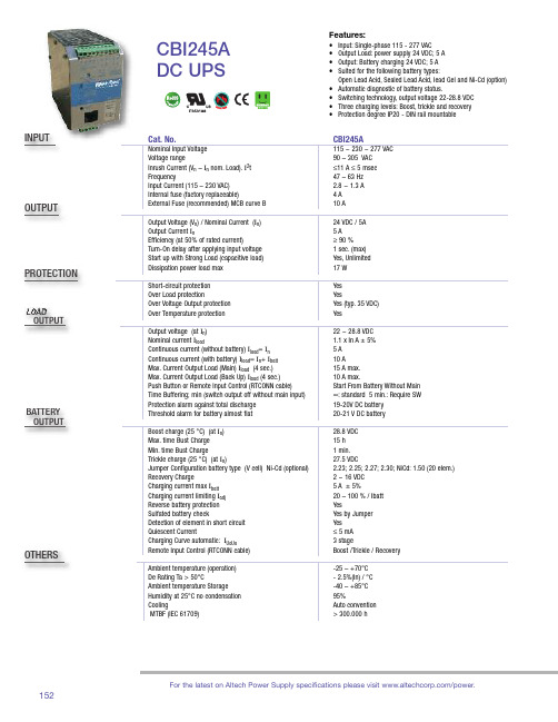
152For the latest on Altech Power Supply specifications please visit /power.CBI245A DC UPS Features:•Input: Single-phase 115 - 277 VAC •Output Load: power supply 24 VDC; 5 A •Output: Battery charging 24 VDC; 5 A •Suited for the following battery types:Open Lead Acid, Sealed Lead Acid, lead Gel and Ni-Cd (option)•Automatic diagnostic of battery status.•Switching technology, output voltage 22-28.8 VDC •Three charging levels: Boost, trickle and recovery •Protection degree IP20 - DIN rail mountableOUTPUT INPUTBATTERY OUTPUTLOADOUTPUT PROTECTION OTHERSCat. No.CBI245A Nominal Input Voltage 115 ~ 230 ~ 277 VAC Voltage range 90 – 305 VAC Inrush Current (V n – I n nom. Load). I 2t ≤11 A ≤ 5 msec Frequency 47 – 63 Hz Input Current (115 – 230 VAC) 2.8 ~ 1.3 A Internal fuse (factory replaceable) 4 A External Fuse (recommended) MCB curve B 10 A Output Voltage (V n ) / Nominal Current (I n )24 VDC / 5A Output Current I n 5 A Efficiency (at 50% of rated current)≥ 90 % Turn-On delay after applying input voltage 1 sec. (max) Start up with Strong Load (capacitive load) Yes, Unlimited Dissipation power load max 17 W Short-circuit protection Yes Over Load protection Yes Over Voltage Output protection Yes (typ. 35 VDC) Over Temperature protection Yes Output voltage (at I n ) 22 ~ 28.8 VDC Nominal current I load 1.1 x In A ± 5% Continuous current (without battery) I load = I n 5 A Continuous current (with battery) I load = I n + I batt 10 A Max. Current Output Load (Main) I load (4 sec.) 15 A max. Max. Current Output Load (Back Up) I load (4 sec.) 10 A max. Push Button or Remote Input Control (RTCONN cable) Start From Battery Without Main Time Buffering; min (switch output off without main input) ∞: standard 5 min.: Require SW Protection alarm against total discharge 19-20V DC battery Threshold alarm for battery almost flat 20-21 V DC battery Boost charge (25 °C) (at I n ) 28.8 VDC Max. time Bust Charge 15 h Min. time Bust Charge 1 min. Trickle charge (25 °C) (at I n ) 27.5 VDC Jumper Configuration battery type (V cell) Ni-Cd (optional) 2.23; 2.25; 2.27; 2.30; NiCd: 1.50 (20 elem.) Recovery Charge 2 ~ 16 VDC Charging current max I batt 5 A ± 5% Charging current limiting I adj 20 – 100 % / Ibatt Reverse battery protection Yes Sulfated battery check Yes by Jumper Detection of element in short circuit Yes Quiescent Current ≤ 5 mA Charging Curve automatic: I UoUo 3 stage Remote Input Control (RTCONN cable) Boost /Trickle / Recovery Ambient temperature (operation) -25 – +70°C De Rating Ta > 50°C - 2.5%(In) / °C Ambient temperature Storage -40 – +85°C Humidity at 25°C no condensation 95% Cooling Auto convention MTBF (IEC 61709)> 300.000 h153Altech Corp.®• 35 Royal Road • Flemington, NJ 08822-6000 • Phone (908)806-9400 • FAX (908)806-9490CBI245ADC UPSThe Altech DC-UPS system is built to optimize powermanagement. The available power is automatically allocated between load and battery, supplying power to the load is the firstpriority. For high inrush applications the charging power will reroute automatically to the load. In this case the maximum available current on the load output is two times the value of the device rated current.The Battery Care concept based on algorithms that achieve rapid and automatic charging, battery optimization during charging time, flat batteries recovery and real time diagnostic The Real Time Auto-diagnostic system, monitors battery faults, sulfated battery, short circuit battery elements, reverse polarity connection,battery disconnect. This conditions are detected and identified by the number of blinks of the diagnosis Led.The Altech DC-UPS system is designed to charge and monitor all battery types, by selecting the battery type via jumpers. Thepredefined curves include Open Lead Acid, Sealed Lead Acid, Gel,Ni-Cd (optional) battery types. The charging curve areprogrammed to automatically switch between Recovery Charge,Boost charge and Trickle charge. The continuous battery efficiencymonitoring, reduces battery damage risk and allows a safeoperation in permanent connection.A compact and rugged metal case with DIN rail mounting bracketprovide an easy installation and an IP20 protection.Voltage CurrentFast / Boost Charge Recovery Charge Tickle / Float Charge V o ltage /C u rrent Jumper for Battery Type SelectionSignal Output Contacts Main or Backup Power Yes Battery Power Low Yes Battery Fault Yes Max. Current Rating (Resistive Load)1A 30 VDC/60 VAC Minimum Permissible Current Rating 1mA @ 5 VDC RJ45 Connection Input/Output Temp. Comp. Battery (with ext. probe) Yes - Optional Remote monitoring display Yes - Optional Can Bus NoEnvironmentInsulation voltage (IN/OUT) 3000 VACInsulation voltage (input / ground) 1605 VAC Insulation voltage (Output / ground) 500 VAC Protection Class (EN/IEC 60529) IP20Pollution Degree Environment 2Connection TB, Screw Terminal 2,5 mm² (24–14AWG)Protection class (Ground Connected) Class I Dimensions (WxHxD) 65x115x135 mm 2.56x4.53x5.32 inWeight (approx.)0.6 kg (1.35 Lbs)Safety and EMC Battery charger standard compliance IEC/EN 60335-2-29Safety standards compliance:EN60950 / UL1950 / CEFire Detection and alarm compliance EN54-4 EMC Directive 89/336/EECCharging cycle DIN41773Emission IEC 61000-6-4Immunity IEC 61000-6-2。
多奥英文版本IC卡停车场规格书

IC Card Parking Management System Solution1. Description:Does your Shopping Mall have parking problems as follows:- A capacity crowed at parking lot and often blocked, it is very difficult for customers to find a parking space?- Often have to queue in the passageway, lead to customers very agitated, often get lots of plains?- The queuing time is too long before the mall closed, often cause the charge dispute, even need to release vehicles for free to ease long lines and plaints?- System vulnerability, results a lot of fraud and cash losing?- System break down, cannot offer fortable and quick service for customers?Large Shopping Mall is a place where many shops and brands gathered, provide fortable and quick parking lot experience is a very important aspect of improving service and increasing passenger flow volume of shops, and the spending power of motorists are stronger than other customers, so how to provide a high efficiency, security and stability parking lot is very important for the customer, and the parking lot is the place where gives them first impression and last impression, so choosing what kind of parking equipment for the operation of the whole Shopping Mall has the extremely important influence.In the process of selection, some customers will choose low-cost domestic equipment, and does not take into account the stability of post-stage operation; Some clients understand the importance of stability, but they flinch from the expensive imported equipment. Can’t we have it both wa ys, no high stability and highly cost-effective equipment? Absolutely not! DUOAO is your best choice, it is the perfect bination of domestic enterprises with international top technology, we have a wealth of practical experience in the parking industry.2.Entry Terminal:DAIC-TC-PLC is an Entry Terminal used inDUOAOCenter Charge parking system. It supports Mifare card asparking tickets and provides a fast and easy entrance control of a parking facility. In case of network disconnection, it can still be operated under stand-alone mode; offline data will be saved and then sent back to Central Management Server after network reconnected.A LED display and a multimedia speaker provide a user friendly interface. While a presence of a car is detected at an EntryTerminal, a display and a vocal message will both prompt the driver to push a ticket button for a ticket of Mifare IC card. The ticket number, entry time, terminal ID and site ID are all written into the card ticket. After the card ticket is taken by the driver, the gate will be opened for entering.For those card tickets dispensed but not taken by the driver are recycled and blacklisted, whileback-out card tickets are also blacklisted by the parking system.Standard specs:●Motorized Mifare IC card reader/writer/dispenser/collector: Contactless read/write mechanism.Ticket capacity: 350 tickets.●Embedded Linux system control board.●Isolated digital I/O control board.●4 words LED display with 305mm*75mm /4 and half words LED display with345mm*75mm LED display screen.●Multimedia speaker.●Sub-inter device.●Flexible application and patible with IC card and ID card;●Work with RFID Long range parking reader for hands free and fast entry/exit;●Cabinet:Cold-roll steel sheets with 1.2mm-1.5mm.●Surface treatment: Unoil-Rust remove-Acid wash- Polish- dust removal- Polyester powder coating- Baking paint for metal in high temperature.●Alarm monitoring and control: Real time alarm monitoring and alert to the Central Management Server.●Alarm types: cabinet intrusion/collision, ticket Back-out and stolen tickets information are sent to Central Management Server as blacklist.●Working Temperature : -25 ~70°C.●Relative Humidity:10%-95%.●Electrical : 220VAC,,0.8/0.4A,50/60Hz.●Power: 60W.●Mifare card reader (wall mount type) for season card (subscriber) system.●Secondary card dispenser for a dual card dispensing system of a total of 600 tickets capacity.●Customized cabinet material and color.●The front panel adopting thenew technology of toughened glass and organic glass, collision avoidance, scratch proof, waterproof design.●Cabinet size:L508mm*H1405mm*W300mm.●Socket size:L348mm*148mm.●40.000 event transaction in Max.3. Cashier Station:DAIC-TC-SF Cashier Station isa PC based POS puter in DUOAOparking system. It supports Mifare ICcard as parking tickets and provides amanned payment service for a parkingfacility. In case of networkdisconnection,It can still be operated understand-alone mode; offline data will besaved and then sent back to CentralManagement Server after networkreconnected.PM800CCP Cashier Station reads the data from a ticket of Mifare IC card received; calculates and displays the required amount of parking fee on the fee display. Once a payment is made, payment pleted data is written back into the Mifare IC of the card ticket for exit validation later. A printed receipt is available upon request.Standard specs:POS puter:✧Resolution: 1024×768✧Luminance: 250cd/㎡✧Color: 16.7M✧Contrast ratio; 600:1✧Touch Systems:Military resistance touch screen (Single point of up to 35 million times)(USB/RS232Optional touch card)✧Main control broad:QC-1037✧CPU: Intel Cedar Trail series CPU 1037 1.8G✧Memory:2GB DDR3-1333 SDRAM(MAX 8G)✧Storage:2.5" SATA II SSD-32G/HDD-500GSystem Parameter:✧Main board:QC-1037✧CPU: Intel® 1037 Dual Core✧Memory: DDR3 1333MHz✧Chip Group: Intel® N10 Express Chipset✧SATA✧SATA II 3GB/s HDD/SDD✧SATA III 6GB/s HDD/SDD✧M-SATA✧LAN: Realtek RTL8111DL (100/1000Mbps)✧Audio: Realtek ALC887 HD Audio Codec integrated✧Storage: 1*2.5 " SATA II HDD-500G/SSD-32GI/O Interface✧Interface:2×RS232 connection line(4 in Max)✧Printer interface:1×LPT✧Audio output:1×Audio\1×Mic✧Video output:1×VGA、✧Network port:1×LAN✧PS2 port✧Expansion bus:1*PCIex1 Expansion slots✧1*Mini PCI-E Expansion slotsWork Environment✧Operating temperature:-10~60℃✧Save temperature:-30~80℃✧Operation humidity:20~85%✧Earthquake-proof characteristics:3 Grms/5~450HzSoftware Configuration✧Mifare IC card validator:✧Mifare IC card reader/writer✧Receipt Printer:✧Print method: direct thermal.✧Print speed: 25 RPM (6-inch per minute). Paper width: 60 mm.✧Cashier Drawer: 4 trays for bills, 8 trays for coins.✧Electrical: 110 or 220VAC, 50/60Hz.✧POS Application Software : Administration login :Username/Password login or authorization card required;Multiple authority levels can be applied for configuring differrent group of system functions.✧Parking rate configuration downloaded from the server:--Time zone;--week days,--Holidays.--plimentary time--Grace time.✧Fee calculation on lost tickets. Discount selection:--Amount.--Percentage.--Hours.✧Mifare card reader (wall mount type) for season card(subscriber) system.✧Color TFT LCD touch screen for operator display.✧Operator shift report.4.Exit Terminal:DAIC-TC-CK is an Exit Terminal used in DUOAO parkingsystem. It supports Mifare IC card as parking tickets andprovides a fast and easy exit control of a parking facility. Incase of network disconnection, PM-800 can still beoperated under stand-alonemode;on-line data will be saved and then sent backto Central Management Server after network reconnected.A LED display and a multimedia speaker provide the terminal with a user friendly interface. While a presence of a car is detected at the Exit Terminal, a display and a vocal message will both prompt the driver to insert a ticket of Mifare IC card for exit verification. The terminal will open the barrier gate and recycle the ticket if parking ticket is valid for exiting. In case of parking fee not paid or grace time exceeded, the ticket is then rejected to the ticket slot and the driver is prompted to retrieve the ticket, and make payment at an Auto Pay or a Cashier Station.Standard specs:●Motorized Mifare card reader/writer and collector. Contactless read/writemechanism.●Embedded Linux system control board.●Isolated digital I/O control board.● 4 words LED display with 305mm*75mm /4 and half words LED display with345mm*75mm LED display screen.●Multimedia speaker.●Sub-inter device.●Flexible application and patible with IC card and ID card,●Work with RFID Long range parking reader for hands free and fast entry/exit;●Cabinet: Cold-roll steel sheets with 1.2mm-1.5mmPolyester powder coating.●Surface treatment: Unoil-Rust remove-Acid wash- Polish- dust removal- Polyesterpowder coating- Baking paint for metal in high temperature.●Alarm monitoring and control:Real time alarm monitoring and alert to the Central ManagementServer.Alarm types: cabinet intrusion/collision, ticket low/empty, device/ municationerrors ...etc.●Working temperature: -25 ~70°C.●Electrical: 100/220VAC, 0.8/0.4A, 50/60Hz.●Dimensions (W x D x H) : 500mm x 500mm x 1300mm (±3%).●Power: 60W.●Mifare card reader (wall mount type) for season card (subscriber) system.●Customized cabinet material and color.●The front panel adopting the new technology of toughened glass and organic glass,collision avoidance, scratch proof, waterproof design●Cabient size:L508mm*H1405mm*W300mm●Socket size:L348mm*148mm●40.000 event transaction in Max.Exit /Entry Terminal Size5. Intelligent Parking Management SoftwareSelect DUOAO Intelligent Parking Management system, you can only with just a few clicks from anywhere of the world.JTPM-800 is now having a web based interface!Simply login to parking software via a web browser to monitor and control the enter parking facility. All setups the configuration of system, the revenue or other reports inquire can be easily operated with a few finger clicks even from the other side of the world.Main page:--Apie chart of occupancy status--An alarm table of instant alarms--A system tree chart to monitor individual device statusRemote Control--hardware reset or softwareSetup:--System: device variable configuration-All device-Auto Pay Station/Cashier Station-Entry/Exit Terminals--Parking Area.--Parking Rate--Holiday--Discount--Operator accountAuthorization LevelTicket:--Blacklist management--Season card managementReport--Daily revenue--Operator shifts--Monthly revenue--Traffic--Other reports6. Program Features●User friendly interface;--Main functions with graphic icon button for an easy use.●Continuous system monitoring;--DUOAO parking software can continuously monitors all the linked device and reports alarms if any.●Real time status acquiring;--A real-time detailed status of all the linked device can be easily acquired from the device tree chart at main page.●Alarm reporting--Instant alarms are prompted listed in the alarm table on the screen and also saved in database.●Universal parking fee configuration--Designed to easily setup various kinds of parking fee charging scheme--Muitiple rates, time zones, day types, daily/weekly maximum charges,discounts,holidays,plimentary and grace time are all configurable;●Remote control of all linked system device--Hardware reset or software restarted of all linked device;--Open/close automatic gate remotely--Programmable timing output contracts to control peripheral device.●Parking space counting system--Hourly& subscribed space counted respectively.--Vacant number can be sent to a numeric led information display;●Integrated season card system;--Time zone configurable--Anti-Passback control included●System database with a configurable backup schedule and location;●Reports:--Revenue report for Auto-pay stations--Shift report for cashier stations--Transaction report for auditing--Traffic flow report--Daily/weekly/monthly revenue report--Parking duration report●Multi-level administrative authorization implemented:--Each administration level authorized with selected software functions.--Different operator account can be assigned with different administration level. 7. The system highlight:➢It can store, modify or query information by Chinese or English version .➢The software also can be edit to customers own language.➢Connecting the controller to PC directly, execute control mands and transmit parameter by the keyboard and mouse , it’s easy for management staff to grasp all the information.➢Easy for setting system time, buffer time and parking rates, and it can be transmitted to devices through the network.➢Monitoring equipment status and the condition of parking space remaining through network.➢After receiving the alarm of abnormal state from vehicle barrier, it can display and print the malfunction.➢After receiving the alarm signal from a shortage of cards and tickets, it will show on the screen and start warning, and it can receive the invalid ticket information from invoice machinery and transfer it to data bank for managing.➢It will receive alarm signal from the full-automatic toll gate: signal of a shortage of cards, coin box filled up, banknote box filled up and equipment be moved ordamaged.➢When the connection of machine and system malfunction, the system will send a warning signal immediately, in order to rule out malfunction as soon as possible. ➢It can display the situation of remaining parking space.➢When the operator querying the information, the subtitles will display successively, the conversion of page to page can be controlled by buttons.➢You can set the traffic light manually or automatically.➢Transmitting the stall data to the information center by data link.➢You can set publicity wordsand the display time, which will be displayed by a super high screen.8. Configuration List9.System InstallationEntry TerminalInstallation:The Follow photo is the wiring diagram of entry terminal, which has includedPM-800 main parking controller, card dispenser, card issuer, IC card reader of cabinet, IC card reader of dispenser, LED display, car park space display screen, long range parking reader, vehicle loop detector, push button, power supply; The cabinet LED display and car park space display are RS485 interface, and all connect to the LED display interface.Exit Terminal Installation:The following photo is the wiring diagram of exit terminal,which has include PM-800 main parking controller, card collector, IC card reader of cabinet, IC card reader of card collector, LED cabinet display, amount display, long range parkingreader, vehicle loop detector, push button, power supply; The cabinet LED display and amount display are RS485 interface, and all connect to the LED display interface.Outside Device Connection definition:10.1 0.Traffic Island Wiring:The traffic island wiring size should be suggested as follows. All details please according to customer’s different application.11. Terminal Machine (Exit/Entry) Installation:Before all the installation, please confirm the traffic island be built well and the five groups connection line be connected well;(1pcs AC220V power supply line, 1pcs network cable, 1pcs barrier control line with 6 cores; 1pcs loop detector connection line, 1pcs long range card reader connection line (optional)).Drilling hole in the right place of traffic island, and fixed the barrier gate and terminal on the ground by expansion Screws.12. Terminal Machine DebuggingAfter installed, please strictly in accordance with the following steps to debug.●Assembly part checkingVisual inspect all assembly parts which inside of the barrier gate and terminal machine in good condition or not, and the anchor screws working loose or not●Visual inspect all connection line before power onChecking all assembly part connection including (exit/entry terminal machine. barrier gate, long range reader, PC),and checking all output /input connectors working loose or not; If wrong connection or in loose condition, please re-connection and make sure that the connector contact is good.Please use the link tester to test the network cable, and use the multimeter testing the power supply input/output terminal whether there is a short/open circuit or not after visual inspect.●Checking the DIP switch setting right or notAccording to the PM - 800 shell screen printing to setting,Entry DIP1 is off and Exit D1P1 is ON.Check IC card reader DIP switch,DIP1 and DIP2 is ON.Check cabinet LED display address is right or not, DIP1 is ON,DIP2~DIP7 is OFF.Check park space LED display address,DIP2 is ON,DIP1,DIP3,DIP4 is OFF.Check card dispenser working mold(Pre-issued work mode); the card dispenserD1P1 is ON, other are OFF.●All Device Testing After Power onFirstly check all connection without short/open circuit and then observe the red power supply indicators of all accessories are in “on” condition or not after power on, if all indicators turn on that mean power supply work in normal.PM-800 parking controller is power on,the power supply indicator is normally on; and the operation indicator D1 will flashing. Usually will be acpanied by a buzzer and munications lights flashing when power on, If the buzzer always alarm and munication has been flashing, you need to check controller and software connection is well or not. If the controller cannot be connected to the Internet, please check the controller indicator is normal (green light is normally on, yellow light is flashing)When the card dispenser is power on but without any card inside, the card dispenser motor will start to back and forth, and that mean the card dispenser has in normally working status and waiting for put card. The motor will stop when put the card inside.Card machine working state and alarm sound and corresponding operation shown in the following table.no. Work Condition Buzzer Corresponding operation1 power-on self-test2 times Work in normally2 Card is less than the amount of presetvalue (card can still be issued)1 times/intervalAdd card and put card block3 Forward path blocked (card cannot beissued2 times/intervalClean sensor4 Time our error(card cannot be issued) 3times/interval1.Check card thickness ;2.Card with oil or not3.Clean friction gear and card4.Card is excessive deformation ;5. Clean the sensor ofcardpre-issued5 Recycling bin has been filled (card canstill be issued)4 timesconsecutiveTake the card in the recycle bin6 Card box empty 5 timesconsecutiveAdd card and put card blockPut a metal plate on the loops after connection the induction loop to the vehicle loopdetector. The green indicator of vehicle loop detector is turn on, and same time D3 indicator of PM-800 parking controller normally on and with the voice prompt which means the vehicle loop detector connection and loop input signal is right. Remove the vehicle plate, the green indicator will turn off and meanwhile the D3 indicator of PM-800 controller with turn off and which means the vehicle loop detector and induction line connection is right. Or else please checking the loop detector and induction line connection is correct or not.Barrier gate connection testing. According to the PM - 800 parking controller panel screen printing instructions for connecting the barrier gate and controller. Pressing the barrier controller three buttons open/close/stop to testing barrier working status is normally or not.13. Modify IP address of the controllerAfter debugging the devices, please install the server software on the puter, then add the controllers on server management software, and assign the IP address of each controller. After adding controller on the server management software, you need to modify the IP address of the controller and the server IP address. Specific methods: input the IP address of the controller on the GOOGLE browser or Internet explorer browser(After controller PM - 800 connect to power, LED panel will scroll display the IP address of controller and server IP address, if you don’t have viewing screen, please revert the IP address to 192.168.8.99 before login). Then modify the IP address of controller according to clew after login.。
DC-005规格书

弘港科技电子有限公司产品承认书PART APPROVAL SHEET供方名称:客户名称:VENDOR:插孔开关CUSTOMER:供方型号:需方型号:VENDOR PART NO:DC-005CUSTOMER PART NO:送样数量:送样日期:SUBMSSION QUANTITY:SUBMSSION DATE:产品承认书附件目录----样品(V) ----承认书(V) ----产品图纸(V)客户确认签署(盖章):供方确认签署(盖章): SIGN FOR CUSTOMER APPROVAL SIGN FOR VENDOR APPROVAL规格书SPECIFICATIONDESIGNATION系列:DC电源MODEL型号:DC-0051.RATING额定值:DC30V2.5A2.CONSTRUCTION DIMENSION结构尺寸:Apply to the appended drawing:符合附加图纸3.APPEARANCE外观:Have no remarkable damage,crack and rust etc:无明显损伤,裂纹,锈迹等. ITEM专案TEST CONDITION测试条件SPECIFICATION规格4.ELECTRONICAL CHARACTERISTICS.电气性能.4A CONTACT RESISTANCE 接触阻抗Being measured at1KHz small current contactresistance meter.在1KHZ小电流下测量.30mΩmax30毫欧以下.4B INSULATIONRESISTANCE绝缘阻抗Measurements shall be made following applicationof DC500V potential across terminals and acrossterminals and frame for1minute.在端子之间和端子与壳之间加DC500V条件下,持续1分钟测量.100MΩmin100兆欧以上.4C WITHSTANDVOLTAGE耐电压AC500V(50Hz or60Hz)shall be applied acrossterminals and across terminals and frame for oneminute在端子之间和端子与壳之间加AC500V(50HZ或60HZ)条件下,持续1分钟测量.There shall be no breakdown.无击穿现象出现.5.MECHANICAL CHARACTERISTICS.机械性能.5A INSERTION AND WITHDRAWFORCE插拔力Being measure at across spring piece and acrossmatching plug for ergometer用测力计在插头与弹片之间进行测量.Insertion and extractionforce3-15N插拔力3-15N5B TERMINAL STRENGTH 端子强度A static force of500gf being applied in onedirection on the tip of terminal for1minute.一個500克之静负荷施加于端子顶部的一個方向持续1分钟。
mos规格书中英文版

mos规格书中英文版Title: MOS Specifications Book (Chinese-English Version)Abstract:This article presents the MOS (Metal-Oxide-Semiconductor) Specifications Book, providing a comprehensive overview of MOS technology, its components, and operating principles. The Chinese-English version of the book ensures that crucial information about MOS technology is accessible to a wide audience.1. IntroductionThe MOS Specifications Book aims to provide a detailed understanding of MOS technology and its various applications. It covers key aspects such as MOS transistors, fabrication processes, and circuit design considerations. The book is divided into multiple chapters, each focusing on specific MOS-related topics.2. MOS TransistorsThe first chapter of the MOS Specifications Book explores the fundamentals of MOS transistors. It discusses their structure, working principles, and performance characteristics. This section provides valuable insights into MOS transistor operation, including the enhancement and depletion modes.3. Fabrication ProcessesThe second chapter delves into the fabrication processes involved in creating MOS technology. It describes key steps, such as silicon waferpreparation, oxidation, ion implantation, and metal deposition. The book also provides an overview of photolithography techniques used in MOS fabrication.4. Circuit Design ConsiderationsChapter three focuses on circuit design considerations for MOS technology. It discusses concepts like voltage scaling, power dissipation, and noise margins. The book provides guidelines for designing robust, power-efficient MOS circuits, emphasizing the importance of minimizing leakage currents and optimizing timing parameters.5. MOS Memory DevicesThe fourth chapter explores MOS memory devices, including static random-access memory (SRAM) and dynamic random-access memory (DRAM). It explains the basic principles behind these devices, their architecture, and performance characteristics. This section also discusses various memory cell topologies and their trade-offs.6. MOS Image SensorsChapter five provides an in-depth analysis of MOS image sensors. It covers the working principles, pixel architectures, and fabrication techniques used in CMOS imagers. The book highlights the advantages of CMOS image sensors, such as low power consumption and high integration levels.7. Applications of MOS TechnologyThe final chapter of the MOS Specifications Book discusses the diverse applications of MOS technology. It examines MOS circuits in areas such asmicroprocessors, analog and digital integrated circuits, and power electronics. This section showcases the versatility and widespread adoption of MOS technology.ConclusionThe MOS Specifications Book (Chinese-English Version) offers a comprehensive understanding of MOS technology for a diverse audience. Its detailed chapters covering MOS transistors, fabrication processes, circuit design considerations, memory devices, image sensors, and applications make it an invaluable resource for students, researchers, and professionals in the field. The book's accurate and concise presentation ensures an enjoyable reading experience without compromising the flow of information.。
中英文船舶规格书 6

PART VI ELECTRIC PART第6部分-电气部分 (1)SECTION 1GENERAL总述 (1)1-1General总述 (1)1-2Arrangement of Equipment设备布置 (1)1-3 Name plate铭牌 (2)1-4Painting colors油漆颜色 (2)1-5Mark and Arrangement of Bus Bar 汇流排的标志和布置 (3)SECTION 2WIRING 第2节-接线 (4)2-1Wiring system布线系统 (4)2-2Cable Application电缆的敷设 (5)2-3Cable Installation 电缆敷设 (5)SECTION 3PRIMARY SOURCE第3节-初级电源 (7)3-1General总述 (7)3-2Main Generators主发电机 (7)3-3Emergency Generator应急发电机 (8)3-4Main Switchboard主配电板 (9)3-5Emergency Switchboard应急配电板 (13)3-6 Shore Connection Box 岸电箱 (14)3-7Test Panel电工试验板 (15)3-8Navigation Watch Console航行驾控台 (15)SECTION 4SECONDARY SOURCE第4节-次级电源 (17)4-1Transformers变压器 (17)4-2Storage Batteries and Battery Charging Board 蓄电池和蓄电池充放电板 (18)SECTION 5DISTRIBUTION SYSTEM第5节-配电系统 (19)5-1Electric Distribution电源分配 (19)5-2Section and Distribution Boards 区配电板和配电盘 (19)5-3Connection boxes and Branch Boxes接线盒和分线盒 (20)SECTION 6POWER SYSTEM第6节-动力系统 (21)6-1Motors马达 (21)6-2Starters起动器 (22)6-3Electric Warmer for Room 舱室电加热器 (24)SECTION 7LIGHTING SYSTEM第7节-照明系统 (25)7-1General总述 (25)7-2Lighting fixtures照明灯具 (25)7-3General Lights通用照明 (27)7-4Flood Light 投光灯 (29)7-5Portable Type Cargo Lamps 手提型货舱灯 (30)7-6Control of Lighting 灯的控制 (30)7-7Switches 开关 (31)7-8Receptacles插座 (31)SECTION 8NAVIGATION LIGHTS AND SIGNAL INSTRUMENT第8节-航行灯和信号灯338-1Navigation Lights航行灯 (33)8-2Signal Lights信号灯 (33)8-3Suez Canal Signal Lights & Searchlight (220V)苏伊士运河信号灯&探照灯 (34)8-4Panama Canal Steering Light (220V)巴拿马运河操舵灯 (34)8-5Other signal light (220V)其它信号灯。
- 1、下载文档前请自行甄别文档内容的完整性,平台不提供额外的编辑、内容补充、找答案等附加服务。
- 2、"仅部分预览"的文档,不可在线预览部分如存在完整性等问题,可反馈申请退款(可完整预览的文档不适用该条件!)。
- 3、如文档侵犯您的权益,请联系客服反馈,我们会尽快为您处理(人工客服工作时间:9:00-18:30)。
Individual Sheet
1.Scope
This specification relates to DC ceramic disc capacitor intended for use in telecommunication and electronic devices.
2. Part number
□□□101 J 26 C0H F 6 F J 5 A □
⑴⑵⑶⑷⑸⑹⑺⑻⑼⑽⑾⑿
The part number consists of 12 sections. The meaning in each section is as follows:
⑴Capacitor type code
The type code is DCC for temperature compensating disc ceramic capacitors(Class Ⅰ) being 50V of rated voltage, DCT for high dielectric constant disc ceramic capacitors(Class Ⅱ) being 50VDC of rated voltage, DCM for both types being 500V of rated voltage, DCH for both types being 1000V up to 3000V rated voltage, DCG for both types above 3000V rated voltage, and DCS for semi-conductive disc ceramic capacitors (class III, i.e. SBBLC).
⑵Rated capacitance
The first and second digits identify the first and second significant figures of the capacitance, the third digit identifies the multiplier. The capacitance unit is pF.
⑶Capacitance tolerance
⑷Body Dimension code
⑸Temperature coefficient or temperature characteristics
⑹Rated voltage
⑺Lead diameter
⑻Lead length or taped style
⑼Lead style
⑽Lead Spacing
* For the capacitors in bulk packing only. For taped capacitors the lead spacing conform to figure 2 or figure 3.
⑾Letter symbol
The letter symbol is the code using for producing management by manufacturer only.
⑿Figure symbol 0 or 1
The figure “0” means that the products comply with European Union Di rective, i.e. the contents of environment-related hazardous substances in the products are less than the amount to be banned or controlled in RoHS directive.
The figure “1” means that there is no relative command for the products, sometimes may be omitted.
3. Standard atmospheric condition
3.1 Temperature: 15~35℃
3.2 Relative humidity: 45~75%
3.3 Atmospheric pressure: 86~106kPa (860~1060 mbar)
4.Operating and storage temperature range
4.1Operating temperature range:
4.2Storage temperature range: -10 to +40℃
5.Characteristics and test methods
5.1Electrical characteristics and test methods
5.2Mechanical characteristics and test methods
5.3Endurance characteristics and test methods
6. Marking
(1)Temperature characteristic:
The marking of class Ⅰtemperature characteristic is the color block on top of capacitor
The marking of class Ⅱ &Ⅲtemperature characteristic is symbols specified in following table.
(2) Capacitance
When rated capacitance is under 100pF the capacitance marking is value being rated capacitance in unit pF.
When rated capacitance is 100pF or over the capacitance marking is made in third digit method.
(3)Tolerance
The tolerance marking for classⅠis the symbols specified in following table.
The tolerance marking for classⅡ&Ⅲis the symbols specified in following table.
(4) Rated voltage
When rated voltage is 50V the voltage marking is symbol “___” under capacitance marking.
When rated voltage is 500V the voltage marking is symbol “ ” over capacitance marking.
When rated voltage is 1000V or over, the voltage marking is symbols “1KV”, “2KV”, “3KV”, “6KV” over capacitance marking.
(5) Manufacturer
When diameter of capacitor body is 6.5mm or under (for 50V and 500V capacitors) or diameter of capacitor body is 7.5mm or under the manufacturer’s marking is symbol“.” under the last digit of capacitance marking.
When diameter of capacitor body is over 6.5mm (for 50V and 500V capacitors) or over 7.5mm (for 1000V capacitors) the manufacturer’s marking is symbols “SHM”.
Example of marking for class Ⅰ
Examples of marking for class Ⅱ&Ⅲ: a. 50V:
b. 500V:
c. 1000~6000V:
HR R 102K 2KV SHM。