IEC_UL_60950-1_电气间隙详解
UL60950-1-2007标准最新要求 (1)
UL60950-1-2007 标准最新要求本讲义主要内容标准范围Scope定义Definitions标签Label结构Construction电气间隙和爬电距离Clearance and Creepage主要的测试方法及要求Main tests method and requirementUL60950-1-2007General Requirements for Information Technology Equipment.。
UL60950-1-2007UL60950-1-2007安全的一般要求:是在防止人体受到下述危险的伤害, 人体泛指使用者及服务人员此二种类型的人:电击(Electric shock)危险能量(Energy hazards)火灾(Fire)机械及热的危险(Mechanical and heat hazards)辐射危险(Radiation hazards)化学的危险(Chemical hazards)材料及零件(Materials and components)Definition 定义Rated Voltage: 额定电压,由制造厂商标定的电源电压;Rated Current:额定电流,由制造厂商标定的设备输入电流;Rated Frequency:额定频率,由制造厂商标定的电源频率;Rated Frequency Range:额定频率范围,由制造厂商标定的额定频率范围。
Definition定义AC120V,AC100-240V,AC120/240V, DC 24V; 120V, 100-240V, 24V;0.5A, 1.0A, 500mA, 1000mA;50Hz, 60Hz;50-60Hz, 50/60Hz.Definition 定义Movable equipment: 移动式设备-质量小于或等于18Kg且未固定的设备,或者-装有滚轮、小脚轮或其他装置,便于操作人员按完成预定应用的需要来移动的设备。
安规爬电距离与电气间隙
IEC/EN60950 空间距离/Clearances(min) distances(min)保险丝前L N 3mm 3mm初级接地零部件3mm 3mm 保险丝本体3mm 3mm初级次级5mm 6mmIEC/EN60065 空间距离/Clearances(min) distances(min)( 保险丝前)L —N 3mm 3mm 初级—接地零部件3mm 3mm 保险丝本体3mm 3mm初级—次级6mm 6mmIEC/EN60335 空间距离/Clearances(min) distances(min)( 保险丝前)L —N 3mm 3mm 初级—接地零部件3mm 3mm 保险丝本体3mm 3mm 初级—次级(Transformer) 6mm 6mm 初级—次级(Except Transformer) 6mm 6mmIEC/EN61558 空间距离/Clearances(min) distances(min)( 保险丝前)L —N 3mm 3mm初级—接地零部件3mm 3mm 爬电距离/Creepage 爬电距离/Creepage 爬电距离/Creepage 爬电距离/Creepage保险丝本体3mm 3mm初级—次级5.5mm 6mm安全规格(系列标准)注:1、IEC/EN60065适用于:家用电子类产品,例如:电视机,录音机,收音机,VCD,DVD,电子琴,复读机……2 、IEC/EN61558 适用于: 安全变压器及安全隔离变压器, 例如:空调内置变压器, 按摩椅上的变压器,鱼罐内的变压器等, 其实,所有产品均可用此标准, 但是, 由于此标准要求很严, 一般情况下, 我们的产品不申请此产品. 除非其他标准类没含盖的产品或客人特殊要求3 、IEC/EN60335适应于:家用电器类产品,例如:电池充电器,灯具,微波炉等.电气间隙: 两相邻导体或一个导体与相邻带电机壳表面的沿空气测量的最短距离.爬电距离: 两相邻导体或一个导体与相邻电机壳表面的沿绝缘表面测量的最短距离.[size=2] 安全距离[/size]包括电气间隙(空间距离), 爬电距离(沿面距离)和绝缘穿透距离1 、电气间隙: 两相邻导体或一个导体与相邻电机壳表面的沿空气测量的最短距离.2、爬电距离: 两相邻导体或一个导体与相邻电机壳表面的沿绝绝缘表面测量的最短距离.电气间隙的决定: 根据测量的工作电压及绝缘等级, 即可决定距离一次侧线路之电气间隙尺寸要求, 见表 3 及表 4 二次侧线路之电气间隙尺寸要求见表5但通常:一次侧交流部分:保险丝前L—N>2.5mm,L.N PE(大地)>2.5mm, 保险丝装置之后可不做要求, 但尽可能保持一定距离以避免发生短路损坏电源.一次侧交流对直流部分》2.0 mm一次侧直流地对大地》2.5mm (一次侧浮接地对大地)一次侧部分对二次侧部分》4.0mm跨接于一二次侧之间之元器件二次侧部分之电隙间隙》0.5mm即可二次侧地对大地》1.0mm即可附注:决定是否符合要求前,内部零件应先施于10N力,外壳施以30N力,以减少其距离, 使确认为最糟情况下, 空间距离仍符合规定.爬电距离的决定:根据工作电压及绝缘等级, 查表 6 可决定其爬电距离但通常:(1)、一次侧交流部分:保险丝前L—N>2.5mm,L.N大地》2.5mm, 保险丝之后可不做要求, 但尽量保持一定距离以避免短路损坏电源.(2) 、一次侧交流对直流部分》2.0mm(3) 、一次侧直流地对地》4.0mm如一次侧地对大地⑷、一次侧对二次侧》6.4mm,如光耦、Y电容等元器零件脚间距冬6.4mm 要幵槽.⑸、二次侧部分之间》0.5mm即可⑹、二次侧地对大地》2.0mm以上⑺、变压器两级间》8.0mm以上3、绝缘穿透距离: 应根据工作电压和绝缘应用场合符合下列规定:――对工作电压不超过50V(71V交流峰值或直流值),无厚度要求;——附加绝缘最小厚度应为0.4mm;――当加强绝缘不承受在正常温度下可能会导致该绝缘材料变形或性能降低的任何机械应力时的, 则该加强绝缘的最小厚度应为0.4mm. 如果所提供的绝缘是用在设备保护外壳内, 而且在操作人员维护时不会受到磕碰或擦伤, 并且属于如下任一种情况, 则上述要求不适用于不论其厚度如何的薄层绝缘材料;――对附加绝缘, 至少使用两层材料, 其中的每一层材料能通过对附加绝缘的抗电强度试验; 或者:――由三层材料构成的附加绝缘, 其中任意两层材料的组合都能通过附加绝缘的抗电强度试验; 或者:――对加强绝缘, 至少使用两层材料, 其中的每一层材料能通过对加强绝缘的抗电强度试验; 或者:由三层绝缘材料构成的加强绝缘, 其中任意两层材料的组合都能通过加强绝缘的抗电强度试验.4、有关于布线工艺注意点: 如电容等平贴元件,必须平贴,不用点胶如两导体在施以10N力可使距离缩短,小于安规距离要求时,可点胶固定此零件, 保证其电气间隙.有的外壳设备内铺PVC胶片时,应注意保证安规距离(注意加工工艺)零件点胶固定注意不可使PCB板上有胶丝等异物. 在加工零件时, 应不引起绝缘破坏.5、有关于防燃材料要求:热缩套管V —1或VTM—2以上;PVC套管V —1或VTM—2以上铁氟龙套管V —1或VTM—2以上;塑胶材质如硅胶片,绝缘胶带V—1或VTM—2 以上PCB板94V —1 以上6、有关于绝缘等级(1) 、工作绝缘:设备正常工作所需的绝缘(2) 、基本绝缘: 对防电击提供基本保护的绝缘(3) 、附加绝缘: 除基本绝缘以外另施加的独立绝缘, 用以保护在基本绝缘一旦失效时仍能防止电击(4) 、双重绝缘: 由基本绝缘加上附加绝缘构成的绝缘(5) 、加强绝缘: 一种单一的绝缘结构, 在本标准规定的条件下, 其所提供的防电击的保护等级相当于双重绝缘各种绝缘的适用情形如下A、操作绝缘oprational insulationa、介于两不同电压之零件间b、介于ELV电路(或SELV电路)及接地的导电零件间.B、基本绝缘basic insulationa、介于具危险电压零件及接地的导电零件之间;b、介于具危险电压及依赖接地的SELV电路之间;c、介于一次侧的电源导体及接地屏蔽物或主电源变压器的铁心之间d、做为双重绝缘的一部分.C、补充绝缘supplementary insulationa、一般而言,介于可触及的导体零件及在基本绝缘损坏后有可能带有危险电压的零件之间, 如:I、介于把手、旋钮,提柄或类似物的外表及其未接地的轴心之间.U、介于第二类设备的金属外壳与穿过此外壳的电源线外皮之间.川、介于ELV电路及未接地的金属外壳之间.b、做为双重绝缘的一部分D、双重绝缘Double insulation Reinforced insulation一般而言, 介于一次侧电路及a、可触及的未接地导电零件之间,或b、浮接(floating) 的SELV的电路之间或c、TNV电路之间双重绝缘=基本绝缘+补充绝缘注:ELV线路:特低电压电路在正常工作条件下, 在导体之间或任一导体之间的交流峰值不超过42.4V或直流值不超过60V的二次电路.SELV电路:安全特低电压电路.作了适当的设计和保护的二次电路, 使得在正常条件下或单一故障条件下任意两个可触及的零部件之间, 以及任意的可触及零部件和设备的保护接地端子(仅对I 类设备)之间的电压,均不会超过安全值.TNV:通讯网络电压电路在正常工作条件下, 携带通信信号的电路.。
IEC_UL_60950-1_电气间隙详解

想了解 IEC/ UL 60950-1:2000 安全标准如何影响电源供电或电池供电的信息类产品的设计吗?需要变更设计,但却没把握 IEC/ UL 60950-1:2000 的规定对于变更的设计有何影响?本文的问答内容旨在协助您符合 IEC/ UL 60950-1:2000 的安全要求。
第一部分沿面距离 (Creepage Distance)IEC/ UL 60950-1:2000 最小沿面距离的规定载录于 2.10.4 条款中。
敬请参考表 2L 以了解各产品应有的沿面距离要求。
若您的产品所测出的工作电压介于表中指定的两个工作电压值之间,您可利用线性内插法 (Linear Interpolation) 计算出所需要的沿面距离。
请参见表 2L 之附注2。
现在就由以下的举例,示范线性插入法的计算运用。
范例 = 电路信息输入电压:100-240V AC测出的工作电压:365 Vms, 890 V peak污染等级:2材料类别:IIIa 或 IIIbQ1a:如何计算基本绝缘需要的沿面距离?300V 需要的沿面距离 = 3.2mm400V 需要的沿面距离 = 4.0mm(4.0-3.2)÷(400-300)×65=0.523.2+0.52=3.72A1a. 基本绝缘需要的的最小沿面距离 = 3.8mm注意事项:须根据表 2L 之附注2,以无条件进入的方式算到最接近的 0.1 mm 单位。
Q1b. 如何计算加强绝缘 (Reinforced Insulation) 需要的沿面距离?公式:(基本绝缘需要的沿面距离) ×2==== > 3.72×2=7.44A1b. 加强绝缘需要的的最小沿面距离 = 7.5 mm注意事项:须根据表 2L 之附注2,以无条件进入的方式算到最接近的 0.1 mm 单位。
须先将基本绝缘所需的最小沿面距离加倍后,再用无条件进入的方式算到最接近的 0.1 mm 单位。
iec 60950-1标准

iec 60950-1标准IEC 60950-1 是一项国际性的电气电子产品安全标准,其全称为"IEC 60950-1: Information technology equipment - Safety - Part 1: General requirements",中文译为"信息技术设备-安全-第1部分:通用要求"。
本文将对这一标准进行解读,包括标准的背景、范围、主要内容、适用领域、测试方法等方面的详细介绍。
一、标准背景IEC 60950-1 标准起源于对信息技术设备(ITE)的安全性要求的关注。
信息技术设备包括计算机、服务器、网络设备等,在其使用中需要满足一系列的电气、机械、热、辐射等方面的安全性要求,以确保用户和环境的安全。
二、标准范围IEC 60950-1 标准主要涵盖了信息技术设备的安全性要求,其中包括但不限于以下方面:电气安全:对设备内部电气元件、电路和电源的安全性要求。
机械安全:设备的机械结构、外壳和连接部分的设计和制造要求,以防止危险的机械伤害。
热安全:设备在正常使用和异常条件下的热特性,以确保不会引起火灾或热伤害。
辐射安全:设备的辐射特性,以防止对人体和其他设备的不良影响。
危险物质控制:对使用危险物质的限制和控制,以符合环保和人体健康的要求。
三、主要内容IEC 60950-1 标准主要包含以下内容:一般要求:对设备的整体设计、生产和测试的一般要求。
电气要求:包括电气元件的要求、绝缘和绝缘距离的要求等。
机械要求:设备的外壳、连接部分、机械强度和稳定性等的要求。
热要求:设备在正常和异常条件下的热性能要求。
辐射要求:设备产生的辐射和对辐射的抗干扰能力要求。
四、适用领域IEC 60950-1 标准适用于广泛的信息技术设备,包括但不限于:个人计算机和工作站服务器和数据中心设备网络设备,如路由器和交换机存储设备,如硬盘和光盘驱动器打印机和复印机视听设备,如电视、音响系统通信设备,如电话和传真机五、测试方法IEC 60950-1 标准中包含了一系列的测试方法,以确保设备在正常和异常条件下的安全性能。
pcb电气间隙和爬电距离 标准

pcb电气间隙和爬电距离标准
PCB电气间隙和爬电距离的标准一般参考国际电工委员会(International Electrotechnical Commission, IEC) 的相关标准:
- 电气间隙: 根据应用环境和电气等级,IEC 60950-1标准中规定了不同等级电气设备的电气间隙要求,比如基本绝缘等级需要至少达到2.5mm的电气间隙。
- 爬电距离: 根据应用环境和电气等级,IEC 60950-1标准中规定了不同等级电气设备的爬电距离要求,比如基本绝缘等级需要至少达到2.5mm的爬电距离。
除IEC标准外,不同国家和地区还有自己的标准,比如美国有UL标准,欧盟有EN标准等。
在设计PCB时应该结合应用环境和电气等级来确定合适的电气间隙和爬电距离,并遵循相关标准要求。
IEC 60950-1 标准介绍
9 TÜV Rheinland (Shanghai) Co., Ltd.
2019/10/22
重要定義 (裝置的移動性)
• 可移動式設備 (MOVABLE) • ≦18kg 且未加以固定 或
• 設備提供便於移動的方法讓操作者執行使用
• 手持式設備 (HAND-HELD) – 正常使用下用於手持(握)的可移動式設備或任何 設備的一部件
電力系統 屋內配線 無需電力裝置
5 TÜV Rheinland (Shanghai) Co., Ltd.
2019/10/22
安全的原理
• 安全設計的優先考慮順序 • 明定設計的準則用來將危險消除,減少或隔離 • 針對危險加以標示或指示
• 保護的對象 • 使用者(操作者) – 無能力識別危險, 但不故意製造危險狀況 • 維護/維修人員 – 針對顯著的危險, 具有預防危害自身及他人安全的 能力, 但無法預防非預期的危險
擊風險所應用附加於基本絕緣的獨立絕緣
• 雙重絕緣 (DOUBLE INSULATION) – 基本絕緣 + 補充絕緣 • 加強絕緣 (REINFORCED INSULATION) – 提供與雙重絕緣同等級的單一絕
緣系統以防護電擊
• 工作電壓 (WORKING VOLTAGE) – 零件或絕緣在正常使用狀況下的操作電壓 • 均方根值工作電壓 (RMS WORKING VOLTAGE) (含d.c.成分) • 峰值工作電壓 (PEAK WORKING VOLTAGE) (含d.c.成分及設備內部重複性產
7 TÜV Rheinland (Shanghai) Co., Ltd.
2019/10/22
重要定義 (裝置的電氣額定)
60950-1安规测试-TUV培训材料

IEC 60950-1:2005 EN 60950-1: 2006 安全测试要求
Prepared by: Charles Chen
TÜV SÜD Group - TÜV Product Service GmbH Seite 12
工作电压 (2.10.2)
测试方法: • 测试电压:额定电压;测试频率:额定频率; 测试样品接上最大正常负载; • 电源的零线和保护地相接; • 次级电路的功能地接到保护地; • 用示波器测量并记录变压器初级线圈各个引脚分别对次级线圈 各个引脚的电压,包括有效值和峰值; • 示波器设置为直流耦合(DC coupling); • 示波器的电源注意要跟电网电源隔离;
TÜV SÜD Group - TÜV Product Service GmbH
Seite 3
操作人员保护
标准试验指 (2.1.1.1 b) 测试方法: • 将操作人员可拆卸零部件(不包括灯)卸掉,包括熔断器座,并将 操作人员可以触及的门盖等打开,运动部件处于最不利的位置; • 在不施加明显力的情况下,将标准试验指插入到产品外壳的开孔, 样品处于任何可能的位置 (重量 ≥ 40kg 的样品不应翻倒); • 如果标准试验指不能进入样品内部,则改用刚性试验指以30N的 力施加于样品的外壳开孔,假如刚性试验指可以进入的话,用标 准试验指在30N力的情况下重新测试。 合格判定: 标准试验指不能触及2.1.1.1的零部件。
TÜV SÜD Group - TÜV Product Service GmbH Seite 8
UL电气间隙
IEC 60950-1EN 60950-1 (BABT), UL 60950-1/CSA 60950-1-03, AS/NZS 60950.1•Document to briefly cover major differences in current UL1459 & UL1950 requirements affecting signal transformer design•European (EN 60950-1) requirements•ACA/AUSTEL (AS/NZS 60950.1, TS 001) requirements•Upcoming changes to these documentsI. Current Requirements:A. United States and Canada:The first revision of UL 60950-1/CSA 60950-1-03 is the most current safety standard covering all of telecom, business, and computer equipment in the United States and Canada. UL 60950-1 and CSA 60950-1-03 were developed as U.S. and Canadian bi-national standards with the goals of harmonizing U.S. and Canadian safety standards, and obtaining a standard with as few deviations from IEC 60950-1 as possible.The latest word is; new product submittals through July 1, 2006 will be evaluated using all the requirements in UL 60950-1 First Edition, or if requested in writing, evaluated using the requirements in UL 60950, Third Edition. After July 1, 2006 all new product submittals are required to use UL 60950-1 First Edition. Products that are certified by Underwriters Laboratories Inc. to previous ITE standards may continue to be certified without further investigation, unless otherwise communicated by UL. However, any significant changes made to these products will be evaluated to the standard(s) used for new product submittals as of the date of the change request, i.e., either UL 60950 Third Edition or UL 60950-1 First Edition through July 1, 2006, and UL 60950-1 First Edition, thereafter.One of the biggest differences between the old domestic telecom standards (UL 1459 & CSA 225) and the new ITE (information technology equipment) standard (UL 60950-1/CSA 60950-1-03) is that, like EN 60950-1, AS/NZS 60950.1 and other IEC 60950-1 documents, UL 60950-1 generally requires minimum distances between circuits that present an electrical hazard to the user and circuits that are accessible. These distances must be maintained in signal transformers. This is important to Midcom as a telecommunications transformer manufacturer, as UL 1459 and CSA 225 had very few and much less stringent requirements outlined with regard to the construction of signal transformers.B. European Union:To sell in the European Union, it is necessary to demonstrate safety by showing that you comply with the Low-Voltage Directive (73/23/EEC). Simply stated, all the LVD says is that Electrical Equipment for sale in the EU must be safe. The individual signing declarations stating such may be held liable for a false or negligent declaration.Because of this, safety approvals to IEC standards are often obtained. It will be necessary to consider what other directives (EMC, TTE, etc.) you must comply with before selling in the European Union; however, these are not the topics of this briefing. The Information Technology Equipment product safety standard published in the Official Journal of the European Communities is EN 60950-1. The current edition of this is based on first edition of IEC 60950-1. Many other European and Eastern Block countries that are not members of the EU have adopted this standard as theirs for ITE (Information Technology Equipment) product safety.C. Australia:The current ITE product safety standard in Australia is Joint (Australia and New Zealand) Amendment 4 to AS/NZS60950.1. this to is based on the 1st amendment to IEC 60950-1.II. Determination of Insulation Requirements:The underlying principle the IEC 60950-1 standards follow with regard to electrical safety is two levels of protection against electrical shock. This is the key to understanding what type of insulation is required when choosing a transformer, or, for that matter, determining the proper board layout and mechanical design of your equipment to adequately maintain the creepage and clearance distances specified in IEC 60950-1. This document will focus on choosing the correct transformer.A. Levels of insulation:There are 5 levels of insulation defined in the IEC 60950-1 standards. The table below summarizes the definition and level of protection offered by each level of insulation:Table 1.Grade of InsulationDefinition(Summary of IEC 60950-1 definition: See clause 1.2.9 of IEC 60950-1)Level ofProtectionFunctional Insulation needed for the correct operation of the equipment. 0Basic Insulation to provide basic protection against electric shock. 1 Supplementary Independent insulation applied in addition to BASIC INSULATION in case of afailure of BASIC INSULATION.1Double BASIC + SUPPEMENTARY INSULATION 2 Reinforced Single insulation system equivalent to DOUBLE INSULATION 2 Protective Earth Not insulation, but when properly constructed and under the right circumstancescan be used to provide one level of protection against electric shock. See clause2.3.2, 2.3.3.1Two levels of protection are provided by double insulation, reinforced insulation, or basic insulation + proper protective earthing. Basic + basic insulation does not qualify for two levels of protection.B. More complete definition of levels of insulation:A given dielectric barrier or level of insulation is more completely defined in IEC 60950-1 by the:•Grade of Insulation (as defined in the above table) required (see clause 2.9.3)•Working Voltage (1.2.9.6, 2.10.2) the insulation is subjected to.•Pollution Degree (2.10.7).Once these three things are determined, the applicable construction and dielectric withstand voltage requirements can be determined. The WORKING VOLTAGE is defined in clause 1.2.9.6 as “…the highest voltage to which the insulation or the component under consideration is, or can be, subjected when the equipment is operating under normal conditions of normal use.” The rules for determining this voltage are spelled out in clause 2.10.2. Ingeneral, when determining the WORKING VOLTAGE one must consider the voltage the insulation can besubjected to under normal and single fault conditions (two levels of protection). In most cases, this is taken to be the mains voltage (primary side) minus the voltage on the secondary side. In Australia andEurope, the working voltage for telecom line transformers is often required to be the main voltage. This is because of concern over a possible fault condition on the protective earth (see clause 6.1), which will be expounded upon later.C. What are the electrical strength requirements for a given grade of insulation?The electrical strength a given barrier must provide is given in clause 5.2, Table 5B of IEC 60950-1. This will depend on:1. Grade or Level of Insulation2. Working voltage (must consider normal and single fault conditions) the given barrier is exposed to.When taking into account all of the international deviations to the IEC 60950-1 requirements, we recommend that a typical modem transformer designed for international use (especially the EU) be designed to the requirements ofSUPPLEMENTARY INSULATION with a WORKING VOLTAGE of 250VACrms (354Vpeak). Referring to table 5B, the barrier this transformer will be required to provide is 1.5kV of isolation. A power transformer providingREINFORCED INSULATION for the same WORKING VOLTAGE would be required to provide 3.0kV of isolation.D. How does the required level of insulation affect the construction requirements of thetransformer?Construction requirements for given barriers are outlined in clause 2.10. That transformers are subject to these requirements is stated in clause 1.5.4 and normative annex C.2. The requirements of clause 2.10 outline three parameters of concern:1. CLEARANCE DISTANCE (definition, clause 1.2.10.1): “The shortest distance between two conductive parts…measured through air.” Air Clearance is of concern as high transient voltages can arc over, breaching the dielectric barrier. Specified clearances for different conditions are outlined in tables 2H, 2J, and 2K of IEC 60950-1. The required clearance is based on three parameters:a) Working Voltage: For determining the appropriate clearance distance, the peak (not RMS) or DC workingvoltage must be considered. Rules for determining the correct Working Voltage for determiningCLEARANCE DISTANCE are given in clause 2.10.3.2 (for circuits with a direct connection to mains), andclause 2.10.3.3 (for circuits that are isolated from mains).b) Nominal Mains Supply Voltage (often the same as the working voltage in the case of a isolation power orsignal transformer)c) Pollution DegreeThe nominal mains supply voltage plays a role in determining clearance, as clearance is sensitive to transient voltages, and a given level of transient is expected for a given mains supply voltage. The POLLUTION DEGREE is simply a measure of how dirty the operating environment is. In general, the more pollution, the more sensitive the air-gap is to over-voltages. The Working and Nominal Mains Supply voltages are important in determining the appropriate Air CLEARANCE DISTANCE as the expected transients that may cause arcing across the barrier are greater with higher working and nominal mains supply voltages.2. CREEPAGE DISTANCE (definition, clause 1.2.10.2): “The shortest path between two conductive parts…measured along the surface of the insulation.” Given a high enough potential applied between two points on an insulating surface, the right environmental conditions, and enough time, the surface of the insulation willbreak down. This is called tracking, and is a surface phenomenon only. What is left where the tracking hasoccurred is a conducting carbon path. This is the reason for the creepage distance requirements. Creepage requirements are outlined in table 2L of IEC 60950-1 and are dependent on three factors:a) WORKING VOLTAGE, (RMS or DC, not peak voltage) of the given insulation. The rules for determiningthe correct Working Voltage for determining the correct CREEPAGE DISTANCE are given in clause2.10.4.b) Pollution Degree rating of the operating environment (how dirty is the operating environment?), and thec) Material Group – a rating given to polymeric materials that compares their resistance to carbon tracking.This rating is determined by test methods defined by IEC 112 or UL 746C. The following gives the CTIMaterial Group ratings given by IEC 60112, and the CTI PLC (Performance Level Categories) given by UL746C; CTI voltages ratings are given as the highest voltage at which the given material will not failaccording tracking test outlined in UL 746C or IEC 60112:IEC rating(MaterialGroup) UL rating (PLC) Comparative Tracking Index(volts)I 0 ≤600VII 1 400V ≤CTI <600VIIIa 2 250V ≤CTI <400V3175V ≤CTI <250V IIIb 4 100V ≤CTI <175VNone 5 0V ≤CTI <100VThe occurrence of tracking tends to be sensitive to RMS or DC voltages. Contaminants in the environment (Pollution Degree) also play a vital role in how quickly a material will break down. A typical office or home environment is considered Pollution Degree 2 as defined by IEC 60950-1 and its daughter standards. The better a material performs (higher voltage rating) in the CTI test, and the lower the pollution degree, the lesser the required creepage distance.3. Distance through insulation: Clause 2.10.5.1 outlines these requirements. REINFORCED andSUPPLEMENTARY INSULATION both require a minimum distances through insulation of 0.4mm, 2 layers ofthin sheet material each of which will withstand the given Electrical Strength test, or 3 layers, of which anycombination of 2 layers will withstand the Electrical Strength test. BASIC INSULATION does not have anythrough insulation distance requirement, except that the vast majority of authorities will not consider enameledmagnet wire insulation as suitable for BASIC INSULATION in most cases.2. Electrical Strength: Determination of the proper Electrical Strength of the Insulation depends on the WorkingVoltage (peak or DC), and whether or not the barrier is in a circuit with a direct connection to mains. Rules fordetermining the appropriate Working Voltage to figure the correct Electrical Strength test are given in clause2.10.2 and clause 5.2 (see Table 5B). It is necessary that a transformer meet both the construction andelectrical strength requirements outlined in the standard. Meeting the electrical strength requirements alone isnot enough! A transformer providing 10kV of isolation, yet not meeting any of the required creepage,clearance, or through insulation requirements will buy you nothing!III. Accessible circuits and Hazardous circuits.If a circuit is accessible, it must meet the requirements of either a SELV (Safety Extra Low Voltage) CIRCUIToperating below a HAZARDOUS ENERGY LEVEL, or a LIMITED CURRENT CIRCUIT. These requirements areoutlined in clauses 2.2 and 2.4 of IEC 60950-1 (make sure to refer to the particular country standard, as the UL,EN, and AS/NZS standards have some differences). In general, an accessible circuit must operate below aHAZARDOUS VOLTAGE (clause 1.2.8.5, …60V DC or 42.4 V-peak) under normal and single fault conditions (two levels of protection are implied here). As primary power (the wall outlet) is clearly hazardous, two levels ofprotection are required between this and accessible circuits. Below is a table summarizing circuit classifications in terms of safety according to IEC 60950-1.Table 2.Circuit Clause Definition HazardLevel1 Primary Circuit 1.2.8.3 Circuit directly connected to supply mains or other equivalentsource.2 Secondary Circuit 1.2.8.4 No direct connection to PRIMARY POWER or mains. -Hazardous Voltage Secondary Circuit 1.2.8.51.2.8.4SECONDARY CIRCUIT operating at a HAZARDOUSVOLTAGE2ELV (Extra Low Voltage) Circuit 1.2.8.6 SECONDARY CIRCUIT operating below a HAZARDOUSVOLTAGE (42.4 Vpeak or 60 V DC) but does not meet SELVor LIMITED CURRENT CIRCUIT requirements.1TNV (Telecommunication Network Voltage) Circuit 1.2.8.10 A SECONDARY CIRCUIT carrying TELECOMMUNICATIONSSIGNALS under normal operating conditions.1TNV-3 1.2.8.13 Telecommunications line exposed to over-voltages, and carriesRinging voltages up to 200Vpeak to ground and 300V peak topeak.1TNV-2 1.2.8.12 Same as TNV-3 except not exposed to over-voltages. 1 TNV-1 1.2.8.11 Low Voltage line, operating under 60VDC under normaloperating conditions.-SELV (Safety Extra-Low Voltage) Circuit 1.2.8.72.2A SECONDARY CIRCUIT operating under a HAZARDOUSVOLTAGE (42.4Vpeak, 60V DC) under normal and single faultconditions.Limited Current Circuit 1.2.8.62.4 A SECONDARY CIRCUIT from which the current that can be drawn is not hazardous under normal and single fault conditions.1 The Hazard Level is equivalent to the level of protection number in Table 1. These numbers are not taken from any IEC 950 standard, but are merely meantas an aid for the purposes of this technical note in understanding these requirements. Table 0.1 of IEC 950 lays out the isolation requirements between differenttypes of circuits quite well.IV. More on the Telecommunications Network:TNV has been divided into three categories. One reason this done was to accommodate for the fact thatmany digital telecommunications circuits operate below SELV (Safety Extra Low Voltage) limits. These digital lines, however, cannot be considered SELV as they are outside lines and are therefore subject to over-voltage conditions (power line induction, lightning strikes, etc.). In addition, a telecommunications circuit or line that operates in an environment not exposed to over voltages (perhaps an indoor TNV circuit) does not have the same hazards as an exposed telecommunications circuit. Following is a summary of each TNV circuit category.1. TNV-1: Sections 1.2.8.11 and 2.3.1 of IEC 60950-1: A TNV-1 circuit is defined as a circuita) whose normal operating voltages do not exceed the limits for an SELV CIRCUIT under normal operatingconditions (generally, this means that no cadenced ringing signals are allowed on TNV-1 circuits), and onwhich over-voltages from the TELECOMMUNICATIONS NETWORK and CABLE DISTRIBUTION SYSTEMS are possible.2. TNV-2: Sections 1.2.8.12 and 2.3.1: A TNV-2 circuit is defined as, whose normal operating voltages exceed thelimits for an SELV Circuit under normal operating conditions and which is not subject to over voltages fromTELECOMUNICATIONS NETWORKS.a) For voltages other than telephone ringing signals, limits are: Uac/70.7 + Udc/120 ≤ 1. In other words,assuming there is no appreciable AC voltage component on the Telecommunications line (cadenced ringing signals excluded), the maximum allowable DC battery voltage is 120VDC.b) Telephone ringing signal limitations are defined in clauses M.2 and M.3. Annex M.3 defines ringing signallimits as 300Vpeak to peak and 200V peak to ground.3. TNV-3: Section 1.2.8.13 and 2.3.1: TNV-3 circuit limitations are identical to TNV-2 circuits, except that they areexposed to outside plant over voltage conditions (power cross, lightning, etc.).V. Telecom Interface Transformer Requirements:Generally, one level of protection is required between the telephone network (TNV CIRCUITS) and any accessible circuits (SELV or LIMITED CURRENT). The reason for this is that, while TNV is not considered hazardous in the sense that a primary power circuit is, one level of protection is still necessary to protect the user from hazardous conditions such as lightning strikes, power line induction, etc. In addition, ringing voltage signals on theTelecommunications Network can have voltages on the order of hundreds of volts. Contact with these voltages is often not a pleasant experience. In general, when considering the most stringent national deviations to IEC 60950-1, you will need a transformer that provides SUPPLEMENTARY INSULATION rated for a 250VAC WORKING VOLTAGE for a PRIMARY CIRCUIT (see clause 6.2 of EN 60950-1). These requirements are not only designed to protect the equipment user from hazards, but also the telephone network service personnel from possible fault conditions related to bad grounding.Applicable Creepage, Clearance, and Electrical Strength requirements for TelecomTransformers(assuming transformer providing the isolation between TNV-2 or TNV-3 circuit and SELV circuit)UL 60950/CSA No. 60950-1-03, EN 60950-1, and AS/NZS 60950.1Insulation WorkingVoltage Creepage Distance ClearanceDistance1Test VoltageBASIC120VDC 1.5mm (CTI III)1.1mm (CTI II)0.8mm (CTI I)N/A N/ABASIC150VDC 1.6mm (CTI III)1.1mm (CTI II)0.8mm (CTI I)N/A N/ASUPPLEMENTARY250 VAC(354Vpeak)2.5mm (CTI III)1.8mm (CTI II)1.3mm (CTI I)2.0mm(1.5mm)1500 VACAustralian Deviation 3000VAC Electrical Strength and 7.0kV surge test required between Network connection and Headset or Handset.3000VAC Electrical Strength and 2.5kV surge test required between Network connection and equipment other than Handsets or Headsets expected to be touched during normal use.1500VAC Electric Strength and 1.5kV surge test required between Network connection to circuitry and parts that can be touched, and connections to other equipment.1. Numbers in parenthesis only apply if manufacturer has an approved quality plan.2. 1500VAC required between outside plant network connection and handheld parts. See clause 6.2.1, 6.2.2.1, and6.2.2.2.3. See Australian deviations to clauses 6.2.2.1 and 6.2.2.2 below concerning electrical strength testing at networktermination.4. See Annex M.3 of IEC 60950-1, UL 60950-1/CSA No. 60950-1-03, EN 60950-1, and AS/NZS 60950.1.There seems to be a misconception that REINFORCED INSULATION is required between TNV and SELV. This is not true.REINFORCED INSULATION is only required for a telecom signal transformer if there is a HAZARDOUSVOLTAGE involved. By definition (clause 1.2.8.5), TNV, SELV, and LIMITED CURRENT CIRCUITS do not have HAZARDOUS VOLTAGES on them; therefore there is generally no need for a REINFORCED barrier. There are some cases (span powering) where voltages on the telecom network exceed TNV limits. In this case, something more than SUPPLEMENTARY INSULATION may be needed. REINFORCED INSULATION may also be needed if, for some reason, there is a HAZARDOUS VOLTAGE on the equipment side of the telecom line isolationtransformer. This would be necessary to protect network service personnel.VI. Power transformer requirements:Power transformer requirements are not as straightforward as the telecom transformer requirements as these depend much more on the particulars of your circuit. What are you isolating from what? Are you using protective earth as one level of protection? Additional clearance distances may be needed depending on how high repetitive voltage spikes are if you are using a switch mode type power supply. Once you figure out your working voltages, how many levels of protection your transformer will provide, etc., you can proceed in the manner outlined above.The same tables and requirements in determining creepage, clearance, and distance through insulation apply for power and telecom signal (i.e. modem, DSL) transformers. Be aware that additional overload testing requirements outlined in annex C.1. also apply to power transformers.Applicable Creepage, Clearance, and Electrical Strength requirements for Power Transformers (Pollution Degree 2)UL 60950-1/CSA 60950-1-03, EN 60950-1, and AS/NZS 60950.1INSULATION WORKINGVOLTAGE CREEPAGEDISTANCECLEARANCEDISTANCE*TESTVOLTAGEBASIC120VAC 1.5mm (CTI III)1.1mm (CTI II)0.8mm (CTI I)1.0mm(0.5mm)1000VACREINFORCED120VAC 2 x above 2 x above2000 VACBASIC250 VAC 2.5mm (CTI III)1.8mm (CTI II)1.5mm (CTI I)2.0mm(1.5mm)1500 VACREINFORCED250 VAC 2 x above 2 x above3000 VAC* Numbers in parenthesis only apply if manufacturer has an approved quality plan.A. Significant National Deviations:1. AUSTRALIA: The most significant deviations from IEC 60950-1 regarding the Telecommunications Networkare the deviations of clause 6.2.2.1 and 6.2.2.2. More stringent HI-POT testing is required by Australia at the Network Termination. This may or may not affect ones choice of transformer.2. Northern Europe: Norway, Finland, and Sweden have issues with obtaining a reliable ground, as their soil isnot very conductive due to the rocky soil and almost year round permafrost. As a result, they have manydeviations in clause 6 and elsewhere in EN 60960-1 with regard to the use of earthing as a means ofprotection against electrical shock. In general (each of these countries has their own twist on this issue, and their deviations are defined in different clauses), SUPPLEMENTARY INSULATION for a PRIMARY CIRCUIT (250Vrms working voltage) is required between the Telecommunications Network and any circuit that has aconnection to earth (clause 6.2.1, 6.1.2). Also, grounding is not generally permitted (6.1.1) as a means ofproviding protection against electrical shock (Class II equipment is preferred). Denmark has some issue here also with regard to the connection of surge suppression devices to conductive metal parts.3. US and Canada: The United States and Canada have significant deviations to IEC 60950-1, especiallyconcerning connection to the Telecommunications Network. These deviations, found in UL 60950-1/CSA60950-1-03 include:i. Clause 5.1.8.3 “Limitation for touch current due to ringing signals”:ii. Clause 5.3.6 (e) “Overloading of internal (i.e.cardcage) SELV CIRCUIT connectors and printed wiring board connectors”iii. Clause 6.4 “Protection against over voltages from power line crosses”This section covers requirements to ensure that Telecommunications Equipment does not become a fire orElectrical safety hazard due to Power Line contact or Induction with the TELECOMMUNICATIONS NETWORK.These requirements are similar to the Bellcore GR-1089-CORE and ITU K.20 and K.21 Over-voltage requirements in that they address the same concerns, however, the test condition details differ significantly from the Bellcore or ITU requirements. Clause 6.4 is not found in IEC 60950-1, EN 60950-1, or any other IEC 950 documents. The UL 60950-1/CSA 60950-1-03 clause 6.4 Over-voltage requirements are the same as those found in clause 58 of UL 1459. The reason that this requirement is not found in other IEC documents is that overhead power lines and telephone lines in close proximity to one another are not common in many other countries. This testing is done in both a common mode (longitudinal) and differential mode (metallic) manner. The longitudinal testing should have little impact on the transformer, as the highest potential this is done at is 600V. One of these tests is done for between ½ hour to 7 hours…so, if a flaky isolation transformer is used, it is likely to fail. The metallic test on the other hand can be very destructive to the transformer, as large currents (up to 2.2 amps for ½ to 7 hours duration) are dumped through the network coil, heating the transformer to very high temperatures. This may result in melting or charring the insulation providing the dielectric barrier. There are two options here to design for compliance: •Over-current limiting protection in front of the transformer• A transformer designed to withstand large currents injected into the network coil.It is possible to design in such a manner to demonstrate compliance and avoid this testing if a suitable fire enclosure, spacing, and suitable current limiting are used.Disclaimer: This document is intended only as an introduction to some of the requirements affecting your choice of a transformer.All said in this document may not be 100% accurate, and is likely to change. It would be prudent to check these facts against the appropriate national standard, and with the appropriate competent approval authority. Midcom cannot take responsibility for any errors made because of the information presented here.。
IEC60950-1讲解

IEC60950-1:2001介紹
IEC 60950-1:2001介紹
4.4 Protective earthing conductors截面積大小,須符 合規章條款 3.2.5 表3B最小尺寸的規定。
IEC 60950-1:2001介紹
4.5 Protective bonding conductors截面積大小,須符 合規章條款 3.2.5 表3B最小尺寸的規定,或規章條款 2.6.3.3.的規定當額定電流大於16A時,且導體大小符合規 章表2D最小尺寸的規定。
下述危險的傷害, 人體泛指使用者及服務人員此二種類
型的人:
危險的種類 電殛 (Electric shock) 危險能量 (Energy hazards) 火災 (Fire) 機械及熱的危險 (Mechanical and heat hazards) 幅射危險 (Radiation hazards) 化學的危險 (Chemical hazards) 材料及零件 (Materials and components) 適用否? Yes Yes Yes Yes YES Yes Yes
IEC 60950-1:2001介紹
3.2.2
3.2.3
3.2.4
IEC 60950-1:2001介紹
3.2.5
3.2.6
3.2.7
3.2.83.2.9
IEC 60950-1:2001介紹 4. 危險的防護
4.1 操作人員可碰觸下列電路或零件:
- ___SELV_電路的裸露零件 - ___限電流_____電路的裸露零件 - 符合2.1.1.1.規定條件的_ TNV 電路
IEC 60950-1:2001介紹
IEC 60950-1:2001介紹
EN60950-1(GB4943)电源测试等内容陈)

二、 测试内容
2.17 外壳热硬力测试(4.2.7)
测试条件: 一定温度下(正常温升时外壳的最高温度+10K) 至少70度 ;运行7小时
二、 测试内容
2.18 插头扭力 (4.3.6)
判断:< 0.25Nm
二、 测试内容
2.19热要求 (4.5)
测试点 1)关键元件 2)接触外壳
开关电源符合EN /IEC 60950-1(GB 4943) 测试项目简介
主讲:陈付雁
主要内容
一、开关电源组成 二、测试内容(重点) 三、样品需求 四、资料的准备
一 开关电源组成
直插式
桌面式
一 开关电源组成
一 开关电源组成
一 开关电源组成
二、测试内容
假设
2.1 输入电流(1.6.2条EN 60950-1)
结果: 满足标准防触电要求
二、 测试内容
2.12 线拉力(3.2.6)
设备:电子称 卡尺
结果: 线(线芯)位移≤2mm
二、 测试内容
2.13稳定性测试(4.1)
适合的产品: 1 产品≥7Kg 倾斜10°角(注意:可移动件的严酷性) 2 地面产品≥25Kg (25% 重量但不超过250N的力) 3地面产品, 向下施加 800N的力
判断:小于0.25mA
二、 测试内容
2.22 电气强度(5.2) 测试: 输入/输出 输入/外壳(塑料壳需要包裹10X20CM的锡箔)
判断:仪器未报警为合格
二、 测试内容
2.23 附录 C 变压器输出过载和输出短路
三、样品需求
样品需求: 成品10件(不超声) 成品5件(超声) 变压器(不浸油)3个;浸油2个 空板 2片
安规标准细则-----60950-1

IEC/EN60950-1安规标准细则二、电气间隙及爬电距离1, L-N 间须至少满足基本绝缘2, 保险丝两引脚间需至少满足基本绝缘3, 初次级电路之间,光藕初次级之间,变压器初次级之间(含初级绕组/初级PIN/初级铜箔对次级绕组/次级PIN/次级铜箔),Y电容初次级间均需满足双重绝缘或加强绝缘;初级带电部件同外壳外部可触及部位间需满足最少0.4mm的穿透绝缘或双重绝缘/加强绝缘要求参考IEC60950-1 table 2H,2J,2L,基本绝缘,附加绝缘,加强绝缘(或双重绝缘)需满足以下要求(工作电压以250V AC 或354V峰值计算):基本绝缘/附加绝缘: 电气间隙CL:2..mm Min, 爬电距离2.5 mm Min双重绝缘/加强绝缘: 电气间隙CL:4..mm Min, 爬电距离5.0 mm Min备注1:计算电气间隙及爬电距离,允许对内部零件施加10N的力备注2:计算电气间隙及爬电距离时,污染等级以2级计备注3:计算电气间隙及爬电距离时,物料级别通常为IIIb备注4:计算爬电距离时,允许用插值法三、高压及绝缘要求1备注:开关电源建议用DC电压进行高压测试.2、绝缘电阻IEC/EN60950-1对绝缘电阻无要求.四、正常温升(通常带满载进行测试)1, 测试电压a,测试电压为电源电压的+6%- -10%,或b, 额定电压为230V时, 测试电压为230V的+/-10%,或c, 生产商指定的更宽的电压范围2,测试频率为50HZ 和/或60HZ3, 环境温度最大的环境温度为25度或生产商指定的更大值4, 绕阻允许的最高温度T《零件允许的最高温度+环境温度-生产商指定的最大的环境温度举例:B级绝缘物料允许的最高温度为120度, 测试的环境温度为25度,-若生产商没有指定最大的环境温度,则T《120+25-25,即T《120度(热偶法测试时T还需减10度)-若生产商指定最大的环境温度为40度,则则T《120+25-40,即T《105度(热偶法测试时T还需减10度) 具体零件的温度限定见表4B5,正常温升测试的接收标准测试过程中,温度保险丝及电流保险丝不允许动作,零部件温度不得超出表4B的要求,测试后产品需立即通过高压测试五、异常测试(通常带满载进行测试)1, 测试电压a,测试电压为电源电压的+6%- -10%,或b, 额定电压为230V时, 测试电压为230V的+/-10%,或c, 生产商指定的更宽的电压范围2,测试频率为50HZ 和或60HZ3, 环境温度最大的环境温度为25度或生产商指定的更大值4,测试方法a)开路或短路半导体零件和电容b)组合电路中会导致出现能量过分消耗的内部错误c)满足双重绝缘或加强绝缘的Y电容不必进行单一故障测试5, 异常测试的接收标准异常测试过程中不允许出现:---火蔓延到设备外部,并且---发出金属融化物---外壳出现变形致使电气间隙及爬电距离不符要求---A级绝缘物料温度超过150度, E级绝缘物料温度超过165度,B级绝缘物料温度超过175度,F级绝缘物料温度超过190度,H级绝缘物料温度超过210度异常测试过程后不允许出现:-----高压失败六、接触电流(泄露电流)---可接触不见及电路没有连接到保护接地时,接触电流0.25mA Max---手持设备测试设备端子通过主保护接地端子时, 接触电流0.75mA Max---可移动设备测试设备端子通过主保护接地端子时, 接触电流3.5mA Max---固定设备或其它设备, 接触电流3.5mA Max七、机械要求1, 外壳需能承受250N的固定力5 S2, 产品外壳内的零件均需承受10N的固定力5 S3, 直插式设备对排插产生的力矩不得超过0.25Nm4, 直插式设备跌落要求:产品需承受高度为1米的跌落3次5, 台式设备的水平表面需承受直径为50mm重量为500克的钢球从1.3m高度自由跌落的冲击, 垂直表面则需承受钢球从1.3m高度进行的摆击测试6,应力缓解测试: 产品需承受至少70度(或外壳正常温升测试时的最大温度加10K,取较大值)7小时-------完成了1-6的测试后,试验指不允许接触到危险带电部件(超过42.4V AC 或60V DC为危险电压) )且高压测试必须仍然符合要求.7、电源线的相关要求:a,电源线线材要求电源线以不可拆卸方式连接的设备总重不超过3公斤的, PVC包胶线材最低级别为227IEC52(最低为H03VV系列线材); 超过3公斤的, PVC包胶线材最低级别为227 IEC53(最低为H05VV系列线材)如电源线以可拆卸方式连接的, PVC包胶线材最低级别为227 IEC52(最低为H03VV系列线材), 设备没有重量限定.如有接地保护, 芯线颜色须为绿/黄.b, 电源线截面积要求c,电源线长度要求---使用了0.5mm2线材作为电源线时,电源线长度不得超过2米, 其余情况对电源线长度无要求---例外特别地,UL60950-1要求产品外部的连接线不得超过3.05m,且需使用标示了温度/电压值的VW-1 或FT-1或更好的线材.d, 电源线拉力要求1秒, 线材位移不能大于2mm.------参考标准IEC60950-1:2001.。
IEC60950-1 安规要求简介
或任何类型设备的一个部件
2020/3/3
18
设备级别
固定:Stationary equipment which is fastened or otherwise secured at a specific location.
直插式:预定使用中不使用电源线,电源插头 和设备外壳构成一整体、其重量是靠墙上插 座来承载的设备。
2020/3/3
3
IEC 60950-1:2001介紹
- Electric shock
電殛的發生情形是因為有電流通過人體,只要有數毫安培的電 流,即可對正常健康人造成影響,並且有可能因不自覺地反應而 造成間接性危險。當然,更大的電流會造成更危險的情形。一 般而言,在乾燥情形下,小於40Vpeak或60Vdc的電壓,通常視為 不具危險的電壓。但是,可被觸碰的零件或是提把皆應接至大 地或是將其適當地隔離之。
2020/3/3
6
IEC 60950-1:2001介紹
- Mechanical hazards 機械的危險是因下列原因而產生: - 設備的機構穩定度及結構穩固 - 避免結構上銳邊尖角 - 受危險可動零件所傷 - 受陰極射線管或高壓燈泡爆裂的碎片所傷 降低機械的危險的方式有: - 設備的銳邊或銳角___圓__弧_化__ - 提供___安_全__內__鎖___裝置 - 提供___防__護_罩___ - 適當的____穩_定__度____設計 - 選用陰極射線管及高壓燈泡具___防__爆___功能 - 當無法避免使用者會因接觸而造成機械危險的區域時須 提供___標_示___以警告使用者
• (短时工作):正常负载下,在一段规定的时间 内进行工作,这种工作是从设备处在冷态条件下 开始,在每一段工作时间之间相隔有足够的时间 使设备冷却到室温。
UL 60950 _电气部分测试
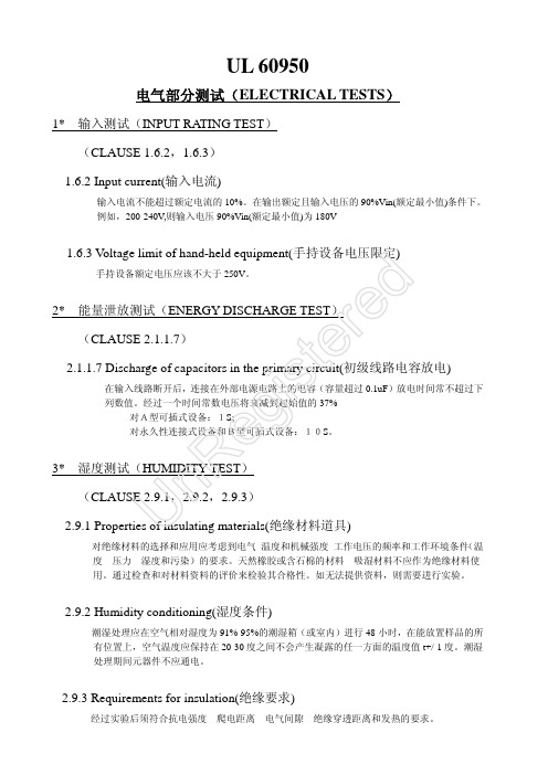
Vdc ≤20 20<Uoc≤30 30<Uoc≤60
A ≤8.0 ≤8.0 ≤150/Uoc
≤5*Uoc ≤100 ≤100
a、 oc 为断开所有负载电路所测得的输出电压。电压为正弦交流电压和无纹波
is 直流电压。对于非正弦交流电压和带有大于 10%峰值的纹波的直流电压,
峰值电压不应超过 42.4V。
设备的设计应尽可能地限制因机械、电气过载或故障,或者因异常工作或使用不当而造成 着火或电击危险。设备在出现异常时,操作人员的安全应仍保持在本标准的含义范围内, 但不要求设备仍处于完好的工作状态。(如短路或开路输入电解、整流桥堆、开关组件、 变压器的绕组、光偶、输出整流二极管、输出电感、稳压电路等) (可以使用熔断器、热断路器、过流保护装置来提供充分的保护。)
潮湿处理应在空气相对湿度为 91%-95%的潮湿箱(或室内)进行 48 小时,在能放置样品的所 有位置上,空气温度应保持在 20-30 度之间不会产生凝露的任一方面的温度值 t+/-1 度。潮湿 处理期间元器件不应通电。
2.9.3 Requirements for insulation(绝缘要求)
经过实验后须符合抗电强度、爬电距离、电气间隙、绝缘穿透距离和发热的要求。
Vpeak or d.c.
Vpeak or d.c.
peak or d.c.
or 60Vd.c.
1000
见表 5B
1500
第二部分
500
基本绝缘 附加绝缘 加强绝缘 (双重绝缘)
1000 2000
1500 3000
见表 5B 第二部分
3000
不试验 不试验
11*、异常测试(ABNORMAL TEST) (CLAUSE 5.3) 5.3.1 Protection against overload and abnormal operation (过载和非正常工作保护)
压敏电阻在IEC 60950-1中的要求解析

STANDARD & APPLICATION引言浪涌被称为瞬态过电压,是电路中出现的一种短暂电流、电压波动,会对电子设备造成危害。
压敏电阻作为信息技术设备等产品中常见的抗雷击浪涌的元器件,可以有效防止这种危害。
但是压敏电阻的使用位置、选型不当都可能造成整机产品不满足安全标准要求。
本文分析了IEC 60950-1: 2013中对压敏电阻的要求,以期对压敏电阻的正确使用提供帮助。
1 压敏电阻相关定义解析电子电路中的浪涌保护元器件,也称为浪涌抑制器。
常见的浪涌抑制器包括电压敏感电阻器(VDR)、碳块、气体放电管(GDT)和其他一些具有非线性电压电流特性的半导体器件,如瞬态抑制二极管(TVS diode)。
其中电压敏感电阻器按其使用材料的不同可分为碳化硅压敏电阻器、金属氧化物压敏电阻器(MOV)、钛酸钡压敏电阻器等,其中以氧化锌为主的金属氧化物压敏电阻是目前开关电源中最广泛使用的浪涌保护元器件。
本文所分析的压敏电阻特指金属氧化物压敏电阻。
2 典型浪涌保护元器件介绍浪涌的保护元器件一般分为开关型和钳位型。
压敏电阻属于钳位型的典型代表,而气体放电管属于开关型的典型代表。
两者的区别也使得在使用时有极大不同。
2.1 压敏电阻压敏电阻实物和电路图中符号如图1,位号一般为VR、RV、X。
压敏电阻在正常电压下呈现高阻抗状态。
当外界浪涌电压超过压敏电阻电压时,压敏电阻会迅速击穿导通,工作电流急剧增大,将电压钳位;当外界电压恢复正常时,压敏电阻又恢复高阻抗状态(图2)。
压敏电阻响应时间快,一般用于电网电源的相线与中线之间。
但由于压敏电阻的电容值较大,不宜直接用于对高频电子系统的保护。
应用于相线与地之间时也要充分考虑漏电流。
2.2 气体放电管气体放电管实物和电路图符号如图3,位号一般为SG、SA。
气体放电管通常采用陶瓷封装,内部充满惰性气压敏电阻在IEC 60950-1中的要求解析Analysis on Request of Varistor in IEC 60950-1北京海关技术中心 武鹏 齐玮摘要阐述了压敏电阻和气体放电管的特性以及两者在开关电源单独或串联使用的情况;详细分析了 IEC 60950-1:2013对压敏电阻的要求,并结合型式试验时的不合格实例及整改方案来加以说明,有助于相关检测人员更好地理解标准。
pcb强电间距标准

pcb强电间距标准
PCB(Printed Circuit Board,印刷电路板)的强电间距标准通常受到电气安全和电气性能等多个方面的考虑。
不同的国家和行业可能会有不同的标准和规定,以下是一些通用的PCB 强电间距标准的概述:
1.IPC标准(美国电子工业联合会):
•IPC-2221A:《印刷电路板设计标准通则》是一份美国IPC 组织发布的标准,其中包括了一些关于电气间隙的要求。
通常,根据电压等级,IPC-2221A建议不同的最小间隙。
2.IEC标准(国际电工委员会):
•IEC 60950-1:《信息技术设备的安全》标准,提供了一些PCB 设计的相关规定,包括强电间距的要求。
3.UL标准(美国保险实验室):
•UL 60950-1:《信息技术设备的安全》标准,涵盖了PCB 设计和电气特性的要求,对强电间距等有具体规定。
4.GB标准(中国国家标准):
•在中国,GB 4943.1-2011《信息技术设备安全第1部分:一般要求》是一个关于信息技术设备安全的标准,也提供
了一些PCB 设计的要求。
5.行业协会标准:
•一些特定行业协会可能会发布与特定应用领域相关的标准,这些标准可能对PCB 设计的强电间距提出了具体的
要求。
请注意,具体的强电间距要求可能会受到设计的应用、电压等级、材料选择等多个因素的影响。
在进行PCB 设计时,最好根据所在国家或地区的相关标准以及具体应用的要求来确定适当的强电间距。
此外,通常还需要与认证机构和生产厂商进行沟通,以确保PCB 的设计符合相关的安全和性能标准。
UL60950 安规间距要求

UL60950安规间距要求(开关电源安规)黄晓康,QQ:513186508欢迎交流一.1.FG接地符号需要加上2.INLET與EMI filter在線路圖上必需用虛線框起來標示3.FUSE的参数與警語需在PCB上標示4.暴露的不带电的金属部分均应与大地相接范例一.输入电压:100-240V AC测出的工作电压:365Vrms,890Vpeak污染等级:2(Pollution Degree2)材料类别:IIIa或IIIb(见上图Pollution Degree2栏下面)如何计算基本绝缘需要的沿面距离?由于测得工作输入电压有效值为365V,在上图中没有.所以需要计算1.先由上图得到300V需要的爬电距离= 3.2mm2.再得到400V需要的爬电距离= 4.0mm3.计算所需增加间距:(4.0-3.2)÷(400V-300V)×(365V-300V)=0.52mm3.2mm+0.52mm=3.72mmA1a.基本绝缘需要的的最小爬电距离= 3.8mm4.如何计算加强绝缘(Reinforced Insulation)需要的爬电距离?公式:(基本绝缘需要的爬电距离)×2====>3.72mm=7.44mm加强绝缘需要的的最小爬电距离=7.5mm注意:根据 2.10.4条款的第三项,万一最小爬电距离小于最小电气间隙(Clearance),则以最小隔空直线间隙做为爬电距离的间距。
第二部分隔空间隙(电气间隔)(Clearance)以下将说明如何针对上例的加强绝缘要求,算出最小的隔空间隙。
敬请参照上面表2K及表2L以进一步了解您的设备之隔空间隙要求。
Q2.如何计算加强绝缘所需要的隔空间隙?根据 2.10.3.2条款规定,当电路的工作电压值(Peak)超过交流电源供电器的电压时,可采取两个步骤决定最小的隔空间隙。
A2.步骤1:请查阅「表2K─初级电路(Primary Circuits)以及初级电路和次级电路(Secondary Circuit s)之间绝缘所需的最小隔空间隙」从最大工作电压的420Vpeak列,您可从表2H找到功能绝缘1.5mm.基本绝缘2.0mm加强绝缘4.0mm按照IEC60950的规定,初级电路的工作电压不超过420V时,功能绝缘1.5mm,基本绝缘2mm,加强绝缘4mm;如果工作电压超过420Vpeak,那么就要把表2K和2L中的数值加起来.由于超过了420Vpeak.所以请查阅「表2L─初级电路的工作电压值超过额定(Nominal)交流电源供应电压值时,绝缘所需的额外隔空间隙」根据最大工作电压890Vpeak,找到2500V列的933Vpeak列.您可从表2L找到功能绝缘额外加距离0.7mm.基本绝缘额外加距离0.7mm.加强绝缘额外加距离1.4mm.最终得到功能绝缘(1.5mm+0.7mm)=2.3mm基本绝缘(2.0mm+0.7mm)=2.7mm加强绝缘(4.0mm+1.4mm)=5.4mm一般要求为:初级基本绝缘(B/S),次级功能绝缘(低压安全电压)(F),初次之间加强绝缘(R)。
- 1、下载文档前请自行甄别文档内容的完整性,平台不提供额外的编辑、内容补充、找答案等附加服务。
- 2、"仅部分预览"的文档,不可在线预览部分如存在完整性等问题,可反馈申请退款(可完整预览的文档不适用该条件!)。
- 3、如文档侵犯您的权益,请联系客服反馈,我们会尽快为您处理(人工客服工作时间:9:00-18:30)。
想了解 IEC/ UL 60950-1:2000 安全标准如何影响电源供电或电池供电的信息类产品的设计吗?需要变更设计,但却没把握 IEC/ UL 60950-1:2000 的规定对于变更的设计有何影响?本文的问答内容旨在协助您符合 IEC/ UL 60950-1:2000 的安全要求。
第一部分沿面距离 (Creepage Distance)
IEC/ UL 60950-1:2000 最小沿面距离的规定载录于 2.10.4 条款中。
敬请参考表 2L 以了解各产品应有的沿面距离要求。
若您的产品所测出的工作电压介于表中指定的两个工作电压值之间,您可利用线性内插法 (Linear Interpolation) 计算出所需要的沿面距离。
请参见表 2L 之附注2。
现在就由以下的举例,示范线性插入法的计算运用。
范例 = 电路信息
输入电压:100-240V AC
测出的工作电压:365 Vms, 890 V peak
污染等级:2
材料类别:IIIa 或 IIIb
Q1a:如何计算基本绝缘需要的沿面距离?
300V 需要的沿面距离 = 3.2mm
400V 需要的沿面距离 = 4.0mm
(4.0-3.2)÷(400-300)×65=0.52
3.2+0.52=3.72
A1a. 基本绝缘需要的的最小沿面距离 = 3.8mm
注意事项:
须根据表 2L 之附注2,以无条件进入的方式算到最接近的 0.1 mm 单位。
Q1b. 如何计算加强绝缘 (Reinforced Insulation) 需要的沿面距离?
公式:(基本绝缘需要的沿面距离) ×2
==== > 3.72×2=7.44
A1b. 加强绝缘需要的的最小沿面距离 = 7.5 mm
注意事项:
须根据表 2L 之附注2,以无条件进入的方式算到最接近的 0.1 mm 单位。
须先将基本绝缘所需的最小沿面距离加倍后,再用无条件进入的方式算到最接近的 0.1 mm 单位。
如果基本绝绿的沿面距离已先采用无条件进入,然后再加倍计算,则计算结果会有 0.1mm 单位的误差。
根据 2.10.4 条款的第三项,万一最小沿面距离小于最小隔空间隙 (Clearance),则以最小隔空直线间隙做为沿面距离的间距。
第二部分隔空间隙 (Clearance)
以下将说明如何针对上例的加强绝缘要求,算出最小的隔空间隙。
敬请参照 2.10.3.2 条款的表 2H 及表 2J 以进一步了解您的设备之隔空间隙要求。
Q2. 如何计算加强绝缘所需要的隔空间隙?
根据 2.10.3.2 条款规定,当电路的工作电压值 (Peak) 超过交流电源供电器的电压时,可采取两个步骤决定最小的隔空间隙。
A2. 步骤1:
请查阅「表 2H ─初级电路 (Primary Circuits) 以及初级电路和次级电路 (Secondary Circuit s) 之间绝缘所需的最小隔空间隙」
IEC/ UL 60950-1 电气间隙详解
从最大工作电压等于交流电供应电压的位置 240 Vac 的 300 Vrms 列,向右移到名称为「N ominal AC mains supply voltage > 150 V 300 V」的电流突波电压 (Transient Voltage) 2 500V 字段,您可从表 2H 找到加强绝缘所需的最小隔空间隙 = 4.0mm。
步骤2:
请查阅「表 2J ─初级电路的工作电压值超过额定 (Nominal) 交流电源供应电压值时,绝缘所需的额外隔空间隙」
在名称为「Nominal AC mains supply voltage > 150 V 300 V」的电流突波电压 (Transie nt Voltage) 2500V 字段里,从横列中选出数值最接近的量测出工作电压值 (= 933V) 。
注意选出的电压不能小于已测出的工作电压。
运用「表 2J」此列,即可找出加强绝缘的「额外隔空间隙」(= 1.4mm)。
将步骤 1 和步骤 2 取得的最小隔空间隙相加─ 4.0+1.4=5.4,就可得到加强绝缘的最小隔空间隙为 5.4 mm。
本范例中,计算出的隔空间隙小于沿面距离,因此我们可判断上例设备的间隙,加强绝缘时所需的沿面距离是 7.5mm。
以上范例属于极为一般的情况,已将任何特定条件除外。
具体详情请参考适用的相关标准。
影响绝缘配置 (Insulation Coordination) 的因素之一─材料类别
材料类别 (Materials Group) 是根据材料的 CTI 值分类。
CTI ─比较留痕指数 (Comparative Tracking Index / 单位:(伏特数) 是依据 UL 746C 或 IEC 60112 测试而产生的数据。
UL 认可组件目录 (Recognized Component Directory) 列出了某些同时符合 UL746C 及 IEC 6 0112 标准的绝缘胶带 (Insulated Tapes)。
在决定最小的沿面距离前,除非事先已知隔空间隙路径中所采用的物料之 CTI 值,否则即设定物料类别为 IIIa 或 IIIb。
若您打算因为更好或更高等级的 CTI 值,而缩小变压器结构中的最小沿面距离,请注意下列事项:
绝缘胶带和加边胶带 (Margin Tapes) 的薄膜 (Film) 及粘着面之 CTI 值,必须依据变压器的结构而有不同的考虑。
注意事项:
最内部线圈 (Winding) 的最小沿面距离,可从加边胶带粘着边或线轴 (Bobbin) 表面等两个较差的 CTI 值中取得。
除了加边胶带的 CTI 值外,还必须检查线轴物料的 CTI 值。
利用较佳的 CTI 值来决定所需的沿面距离可缩减沿面距离的结果。
不过,当工作电压所需隔空间隙大于沿面距离时,您必须以隔空间隙值做为要求的沿面距离值。
外接式已认证电源供应器之玩具电脑在进行上述标准规范认证时,所需进行的测试项目1如下:
•UL60950-1:输入电流测试 (Input Test):单相 (Single-Phase (1.6.2))、电力限制性电源量测 (Limited Power Source Measurements (2.5))、接地保护测试 II (Earthing II (2.6.3.4,
2.6.1)、湿度 (Humidity (2.9.1, 2.9.2, 5.2.2))、稳定度 (Stability (4.1))、电线固定座及抗拉力
测试 (Stain Relief Test (3.2.6))、稳定力测试 (Steady Force (4.2.1 - 4.2.4))、冲击力测试(I
mpact (4.2.5, 4.2.1))、应力强度测试 (Stress Relief Test)、锂电池电流逆充量测 (Lithium Ba ttery Reverse Current Measurement (4.3.8))、加热测试 (Heating Test (4.5.1, 1.4.12, 1.4.
13))、接地漏电流测试(单相/多相;TN/TT 系统) (Touch Current (Single-Phase/Poly-phase; TN/TT System) (5.1, Annex D))、电信网络与缆线系统的极限接地漏电流测试 (Limitation of the Touch Current to a Telecommunications Network and a Cable Distribution System (5.1.8.1))、响铃信号的极限接地漏电流测试 (Limitation of Touch Current due to Ringing Si gnals (5.1.8.3))、电压 (Electric Strength (5.2.2))、异常操作测试 (Abnormal Operation (5.3.
1 - 5.3.8.2))、过负载测试 (Overload of Operator Accessible Connector (5.3.6))。
