i.MX roadmap
Tektronix MDO3000 Series 数字多功能作业仪用户指南说明书
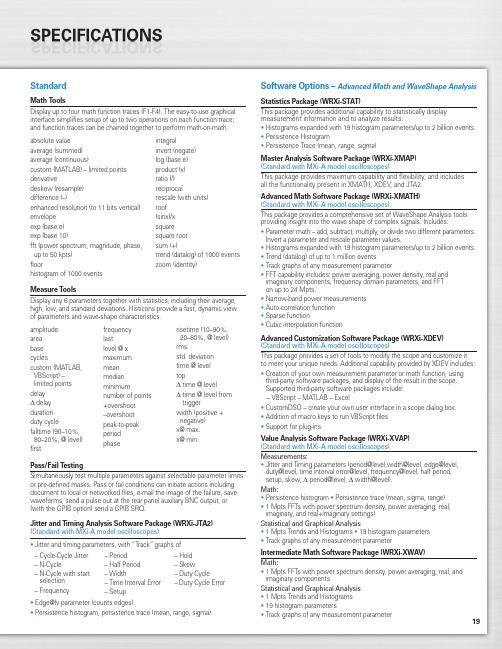
19StandardMath ToolsDisplay up to four math function traces (F1-F4). The easy-to-use graphical interface simplifies setup of up to two operations on each function trace;and function traces can be chained together to perform math-on-math.absolute value integralaverage (summed)invert (negate)average (continuous)log (base e)custom (MATLAB) – limited points product (x)derivativeratio (/)deskew (resample)reciprocaldifference (–)rescale (with units)enhanced resolution (to 11 bits vertical)roof envelope (sinx)/x exp (base e)square exp (base 10)square root fft (power spectrum, magnitude, phase,sum (+)up to 50 kpts) trend (datalog) of 1000 events floorzoom (identity)histogram of 1000 eventsMeasure ToolsDisplay any 6 parameters together with statistics, including their average,high, low, and standard deviations. Histicons provide a fast, dynamic view of parameters and wave-shape characteristics.Pass/Fail TestingSimultaneously test multiple parameters against selectable parameter limits or pre-defined masks. Pass or fail conditions can initiate actions including document to local or networked files, e-mail the image of the failure, save waveforms, send a pulse out at the rear panel auxiliary BNC output, or (with the GPIB option) send a GPIB SRQ.Jitter and Timing Analysis Software Package (WRXi-JTA2)(Standard with MXi-A model oscilloscopes)•Jitter and timing parameters, with “Track”graphs of •Edge@lv parameter (counts edges)• Persistence histogram, persistence trace (mean, range, sigma)Software Options –Advanced Math and WaveShape AnalysisStatistics Package (WRXi-STAT)This package provides additional capability to statistically display measurement information and to analyze results:• Histograms expanded with 19 histogram parameters/up to 2 billion events.• Persistence Histogram• Persistence Trace (mean, range, sigma)Master Analysis Software Package (WRXi-XMAP)(Standard with MXi-A model oscilloscopes)This package provides maximum capability and flexibility, and includes all the functionality present in XMATH, XDEV, and JTA2.Advanced Math Software Package (WRXi-XMATH)(Standard with MXi-A model oscilloscopes)This package provides a comprehensive set of WaveShape Analysis tools providing insight into the wave shape of complex signals. Includes:•Parameter math – add, subtract, multiply, or divide two different parameters.Invert a parameter and rescale parameter values.•Histograms expanded with 19 histogram parameters/up to 2 billion events.•Trend (datalog) of up to 1 million events•Track graphs of any measurement parameter•FFT capability includes: power averaging, power density, real and imaginary components, frequency domain parameters, and FFT on up to 24 Mpts.•Narrow-band power measurements •Auto-correlation function •Sparse function• Cubic interpolation functionAdvanced Customization Software Package (WRXi-XDEV)(Standard with MXi-A model oscilloscopes)This package provides a set of tools to modify the scope and customize it to meet your unique needs. Additional capability provided by XDEV includes:•Creation of your own measurement parameter or math function, using third-party software packages, and display of the result in the scope. Supported third-party software packages include:– VBScript – MATLAB – Excel•CustomDSO – create your own user interface in a scope dialog box.• Addition of macro keys to run VBScript files •Support for plug-insValue Analysis Software Package (WRXi-XVAP)(Standard with MXi-A model oscilloscopes)Measurements:•Jitter and Timing parameters (period@level,width@level, edge@level,duty@level, time interval error@level, frequency@level, half period, setup, skew, Δ period@level, Δ width@level).Math:•Persistence histogram •Persistence trace (mean, sigma, range)•1 Mpts FFTs with power spectrum density, power averaging, real, imaginary, and real+imaginary settings)Statistical and Graphical Analysis•1 Mpts Trends and Histograms •19 histogram parameters •Track graphs of any measurement parameterIntermediate Math Software Package (WRXi-XWAV)Math:•1 Mpts FFTs with power spectrum density, power averaging, real, and imaginary componentsStatistical and Graphical Analysis •1 Mpts Trends and Histograms •19 histogram parameters•Track graphs of any measurement parameteramplitude area base cyclescustom (MATLAB,VBScript) –limited points delay Δdelay duration duty cyclefalltime (90–10%, 80–20%, @ level)firstfrequency lastlevel @ x maximum mean median minimumnumber of points +overshoot –overshoot peak-to-peak period phaserisetime (10–90%, 20–80%, @ level)rmsstd. deviation time @ level topΔ time @ levelΔ time @ level from triggerwidth (positive + negative)x@ max.x@ min.– Cycle-Cycle Jitter – N-Cycle– N-Cycle with start selection – Frequency– Period – Half Period – Width– Time Interval Error – Setup– Hold – Skew– Duty Cycle– Duty Cycle Error20WaveRunner WaveRunner WaveRunner WaveRunner WaveRunner 44Xi-A64Xi-A62Xi-A104Xi-A204Xi-AVertical System44MXi-A64MXi-A104MXi-A204MXi-ANominal Analog Bandwidth 400 MHz600 MHz600 MHz 1 GHz 2 GHz@ 50 Ω, 10 mV–1 V/divRise Time (Typical)875 ps500 ps500 ps300 ps180 psInput Channels44244Bandwidth Limiters20 MHz; 200 MHzInput Impedance 1 MΩ||16 pF or 50 Ω 1 MΩ||20 pF or 50 ΩInput Coupling50 Ω: DC, 1 MΩ: AC, DC, GNDMaximum Input Voltage50 Ω: 5 V rms, 1 MΩ: 400 V max.50 Ω: 5 V rms, 1 MΩ: 250 V max.(DC + Peak AC ≤ 5 kHz)(DC + Peak AC ≤ 10 kHz)Vertical Resolution8 bits; up to 11 with enhanced resolution (ERES)Sensitivity50 Ω: 2 mV/div–1 V/div fully variable; 1 MΩ: 2 mV–10 V/div fully variableDC Gain Accuracy±1.0% of full scale (typical); ±1.5% of full scale, ≥ 10 mV/div (warranted)Offset Range50 Ω: ±1 V @ 2–98 mV/div, ±10 V @ 100 mV/div–1 V/div; 50Ω:±400mV@2–4.95mV/div,±1V@5–99mv/div,1 M Ω: ±1 V @ 2–98 mV/div, ±10 V @ 100 mV/div–1 V/div,±10 V @ 100 mV–1 V/div±**********/div–10V/div 1 M Ω: ±400 mV @ 2–4.95 mV/div, ±1 V @5–99 mV/div, ±10 V @ 100 mV–1 V/div,±*********–10V/divInput Connector ProBus/BNCTimebase SystemTimebases Internal timebase common to all input channels; an external clock may be applied at the auxiliary inputTime/Division Range Real time: 200 ps/div–10 s/div, RIS mode: 200 ps/div to 10 ns/div, Roll mode: up to 1,000 s/divClock Accuracy≤ 5 ppm @ 25 °C (typical) (≤ 10 ppm @ 5–40 °C)Sample Rate and Delay Time Accuracy Equal to Clock AccuracyChannel to Channel Deskew Range±9 x time/div setting, 100 ms max., each channelExternal Sample Clock DC to 600 MHz; (DC to 1 GHz for 104Xi-A/104MXi-A and 204Xi-A/204MXi-A) 50 Ω, (limited BW in 1 MΩ),BNC input, limited to 2 Ch operation (1 Ch in 62Xi-A), (minimum rise time and amplitude requirements applyat low frequencies)Roll Mode User selectable at ≥ 500 ms/div and ≤100 kS/s44Xi-A64Xi-A62Xi-A104Xi-A204Xi-A Acquisition System44MXi-A64MXi-A104MXi-A204MXi-ASingle-Shot Sample Rate/Ch 5 GS/sInterleaved Sample Rate (2 Ch) 5 GS/s10 GS/s10 GS/s10 GS/s10 GS/sRandom Interleaved Sampling (RIS)200 GS/sRIS Mode User selectable from 200 ps/div to 10 ns/div User selectable from 100 ps/div to 10 ns/div Trigger Rate (Maximum) 1,250,000 waveforms/secondSequence Time Stamp Resolution 1 nsMinimum Time Between 800 nsSequential SegmentsAcquisition Memory Options Max. Acquisition Points (4 Ch/2 Ch, 2 Ch/1 Ch in 62Xi-A)Segments (Sequence Mode)Standard12.5M/25M10,00044Xi-A64Xi-A62Xi-A104Xi-A204Xi-A Acquisition Processing44MXi-A64MXi-A104MXi-A204MXi-ATime Resolution (min, Single-shot)200 ps (5 GS/s)100 ps (10 GS/s)100 ps (10 GS/s)100 ps (10 GS/s)100 ps (10 GS/s) Averaging Summed and continuous averaging to 1 million sweepsERES From 8.5 to 11 bits vertical resolutionEnvelope (Extrema)Envelope, floor, or roof for up to 1 million sweepsInterpolation Linear or (Sinx)/xTrigger SystemTrigger Modes Normal, Auto, Single, StopSources Any input channel, External, Ext/10, or Line; slope and level unique to each source, except LineTrigger Coupling DC, AC (typically 7.5 Hz), HF Reject, LF RejectPre-trigger Delay 0–100% of memory size (adjustable in 1% increments, or 100 ns)Post-trigger Delay Up to 10,000 divisions in real time mode, limited at slower time/div settings in roll modeHold-off 1 ns to 20 s or 1 to 1,000,000,000 events21WaveRunner WaveRunner WaveRunner WaveRunner WaveRunner 44Xi-A 64Xi-A 62Xi-A104Xi-A 204Xi-A Trigger System (cont’d)44MXi-A64MXi-A104MXi-A204MXi-AInternal Trigger Level Range ±4.1 div from center (typical)Trigger and Interpolator Jitter≤ 3 ps rms (typical)Trigger Sensitivity with Edge Trigger 2 div @ < 400 MHz 2 div @ < 600 MHz 2 div @ < 600 MHz 2 div @ < 1 GHz 2 div @ < 2 GHz (Ch 1–4 + external, DC, AC, and 1 div @ < 200 MHz 1 div @ < 200 MHz 1 div @ < 200 MHz 1 div @ < 200 MHz 1 div @ < 200 MHz LFrej coupling)Max. Trigger Frequency with400 MHz 600 MHz 600 MHz 1 GHz2 GHzSMART Trigger™ (Ch 1–4 + external)@ ≥ 10 mV@ ≥ 10 mV@ ≥ 10 mV@ ≥ 10 mV@ ≥ 10 mVExternal Trigger RangeEXT/10 ±4 V; EXT ±400 mVBasic TriggersEdgeTriggers when signal meets slope (positive, negative, either, or Window) and level conditionTV-Composite VideoT riggers NTSC or PAL with selectable line and field; HDTV (720p, 1080i, 1080p) with selectable frame rate (50 or 60 Hz)and Line; or CUSTOM with selectable Fields (1–8), Lines (up to 2000), Frame Rates (25, 30, 50, or 60 Hz), Interlacing (1:1, 2:1, 4:1, 8:1), or Synch Pulse Slope (Positive or Negative)SMART TriggersState or Edge Qualified Triggers on any input source only if a defined state or edge occurred on another input source.Delay between sources is selectable by time or eventsQualified First In Sequence acquisition mode, triggers repeatedly on event B only if a defined pattern, state, or edge (event A) is satisfied in the first segment of the acquisition. Delay between sources is selectable by time or events Dropout Triggers if signal drops out for longer than selected time between 1 ns and 20 s.PatternLogic combination (AND, NAND, OR, NOR) of 5 inputs (4 channels and external trigger input – 2 Ch+EXT on WaveRunner 62Xi-A). Each source can be high, low, or don’t care. The High and Low level can be selected independently. Triggers at start or end of the patternSMART Triggers with Exclusion TechnologyGlitch and Pulse Width Triggers on positive or negative glitches with widths selectable from 500 ps to 20 s or on intermittent faults (subject to bandwidth limit of oscilloscope)Signal or Pattern IntervalTriggers on intervals selectable between 1 ns and 20 sTimeout (State/Edge Qualified)Triggers on any source if a given state (or transition edge) has occurred on another source.Delay between sources is 1 ns to 20 s, or 1 to 99,999,999 eventsRuntTrigger on positive or negative runts defined by two voltage limits and two time limits. Select between 1 ns and 20 sSlew RateTrigger on edge rates. Select limits for dV, dt, and slope. Select edge limits between 1 ns and 20 s Exclusion TriggeringTrigger on intermittent faults by specifying the normal width or periodLeCroy WaveStream Fast Viewing ModeIntensity256 Intensity Levels, 1–100% adjustable via front panel control Number of Channels up to 4 simultaneouslyMax Sampling Rate5 GS/s (10 GS/s for WR 62Xi-A, 64Xi-A/64MXi-A,104Xi-A/104MXi-A, 204Xi-A/204MXi-A in interleaved mode)Waveforms/second (continuous)Up to 20,000 waveforms/secondOperationFront panel toggle between normal real-time mode and LeCroy WaveStream Fast Viewing modeAutomatic SetupAuto SetupAutomatically sets timebase, trigger, and sensitivity to display a wide range of repetitive signalsVertical Find ScaleAutomatically sets the vertical sensitivity and offset for the selected channels to display a waveform with maximum dynamic range44Xi-A 64Xi-A 62Xi-A104Xi-A 204Xi-A Probes44MXi-A 64MXi-A104MXi-A 204MXi-AProbesOne Passive probe per channel; Optional passive and active probes available Probe System; ProBus Automatically detects and supports a variety of compatible probes Scale FactorsAutomatically or manually selected, depending on probe usedColor Waveform DisplayTypeColor 10.4" flat-panel TFT-LCD with high resolution touch screenResolutionSVGA; 800 x 600 pixels; maximum external monitor output resolution of 2048 x 1536 pixelsNumber of Traces Display a maximum of 8 traces. Simultaneously display channel, zoom, memory, and math traces Grid StylesAuto, Single, Dual, Quad, Octal, XY , Single + XY , Dual + XY Waveform StylesSample dots joined or dots only in real-time mode22Zoom Expansion TracesDisplay up to 4 Zoom/Math traces with 16 bits/data pointInternal Waveform MemoryM1, M2, M3, M4 Internal Waveform Memory (store full-length waveform with 16 bits/data point) or store to any number of files limited only by data storage mediaSetup StorageFront Panel and Instrument StatusStore to the internal hard drive, over the network, or to a USB-connected peripheral deviceInterfaceRemote ControlVia Windows Automation, or via LeCroy Remote Command Set Network Communication Standard VXI-11 or VICP , LXI Class C Compliant GPIB Port (Accessory)Supports IEEE – 488.2Ethernet Port 10/100/1000Base-T Ethernet interface (RJ-45 connector)USB Ports5 USB 2.0 ports (one on front of instrument) supports Windows-compatible devices External Monitor Port Standard 15-pin D-Type SVGA-compatible DB-15; connect a second monitor to use extended desktop display mode with XGA resolution Serial PortDB-9 RS-232 port (not for remote oscilloscope control)44Xi-A 64Xi-A 62Xi-A104Xi-A 204Xi-A Auxiliary Input44MXi-A 64MXi-A104MXi-A 204MXi-ASignal Types Selected from External Trigger or External Clock input on front panel Coupling50 Ω: DC, 1 M Ω: AC, DC, GND Maximum Input Voltage50 Ω: 5 V rms , 1 M Ω: 400 V max.50 Ω: 5 V rms , 1 M Ω: 250 V max. (DC + Peak AC ≤ 5 kHz)(DC + Peak AC ≤ 10 kHz)Auxiliary OutputSignal TypeTrigger Enabled, Trigger Output. Pass/Fail, or Off Output Level TTL, ≈3.3 VConnector TypeBNC, located on rear panelGeneralAuto Calibration Ensures specified DC and timing accuracy is maintained for 1 year minimumCalibratorOutput available on front panel connector provides a variety of signals for probe calibration and compensationPower Requirements90–264 V rms at 50/60 Hz; 115 V rms (±10%) at 400 Hz, Automatic AC Voltage SelectionInstallation Category: 300 V CAT II; Max. Power Consumption: 340 VA/340 W; 290 VA/290 W for WaveRunner 62Xi-AEnvironmentalTemperature: Operating+5 °C to +40 °C Temperature: Non-Operating -20 °C to +60 °CHumidity: Operating Maximum relative humidity 80% for temperatures up to 31 °C decreasing linearly to 50% relative humidity at 40 °CHumidity: Non-Operating 5% to 95% RH (non-condensing) as tested per MIL-PRF-28800F Altitude: OperatingUp to 3,048 m (10,000 ft.) @ ≤ 25 °C Altitude: Non-OperatingUp to 12,190 m (40,000 ft.)PhysicalDimensions (HWD)260 mm x 340 mm x 152 mm Excluding accessories and projections (10.25" x 13.4" x 6")Net Weight7.26kg. (16.0lbs.)CertificationsCE Compliant, UL and cUL listed; Conforms to EN 61326, EN 61010-1, UL 61010-1 2nd Edition, and CSA C22.2 No. 61010-1-04Warranty and Service3-year warranty; calibration recommended annually. Optional service programs include extended warranty, upgrades, calibration, and customization services23Product DescriptionProduct CodeWaveRunner Xi-A Series Oscilloscopes2 GHz, 4 Ch, 5 GS/s, 12.5 Mpts/ChWaveRunner 204Xi-A(10 GS/s, 25 Mpts/Ch in interleaved mode)with 10.4" Color Touch Screen Display 1 GHz, 4 Ch, 5 GS/s, 12.5 Mpts/ChWaveRunner 104Xi-A(10 GS/s, 25 Mpts/Ch in interleaved mode)with 10.4" Color Touch Screen Display 600 MHz, 4 Ch, 5 GS/s, 12.5 Mpts/Ch WaveRunner 64Xi-A(10 GS/s, 25 Mpts/Ch in interleaved mode)with 10.4" Color Touch Screen Display 600 MHz, 2 Ch, 5 GS/s, 12.5 Mpts/Ch WaveRunner 62Xi-A(10 GS/s, 25 Mpts/Ch in interleaved mode)with 10.4" Color Touch Screen Display 400 MHz, 4 Ch, 5 GS/s, 12.5 Mpts/Ch WaveRunner 44Xi-A(25 Mpts/Ch in interleaved mode)with 10.4" Color Touch Screen DisplayWaveRunner MXi-A Series Oscilloscopes2 GHz, 4 Ch, 5 GS/s, 12.5 Mpts/ChWaveRunner 204MXi-A(10 GS/s, 25 Mpts/Ch in Interleaved Mode)with 10.4" Color Touch Screen Display 1 GHz, 4 Ch, 5 GS/s, 12.5 Mpts/ChWaveRunner 104MXi-A(10 GS/s, 25 Mpts/Ch in Interleaved Mode)with 10.4" Color Touch Screen Display 600 MHz, 4 Ch, 5 GS/s, 12.5 Mpts/Ch WaveRunner 64MXi-A(10 GS/s, 25 Mpts/Ch in Interleaved Mode)with 10.4" Color Touch Screen Display 400 MHz, 4 Ch, 5 GS/s, 12.5 Mpts/Ch WaveRunner 44MXi-A(25 Mpts/Ch in Interleaved Mode)with 10.4" Color Touch Screen DisplayIncluded with Standard Configuration÷10, 500 MHz, 10 M Ω Passive Probe (Total of 1 Per Channel)Standard Ports; 10/100/1000Base-T Ethernet, USB 2.0 (5), SVGA Video out, Audio in/out, RS-232Optical 3-button Wheel Mouse – USB 2.0Protective Front Cover Accessory PouchGetting Started Manual Quick Reference GuideAnti-virus Software (Trial Version)Commercial NIST Traceable Calibration with Certificate 3-year WarrantyGeneral Purpose Software OptionsStatistics Software Package WRXi-STAT Master Analysis Software Package WRXi-XMAP (Standard with MXi-A model oscilloscopes)Advanced Math Software Package WRXi-XMATH (Standard with MXi-A model oscilloscopes)Intermediate Math Software Package WRXi-XWAV (Standard with MXi-A model oscilloscopes)Value Analysis Software Package (Includes XWAV and JTA2) WRXi-XVAP (Standard with MXi-A model oscilloscopes)Advanced Customization Software Package WRXi-XDEV (Standard with MXi-A model oscilloscopes)Spectrum Analyzer and Advanced FFT Option WRXi-SPECTRUM Processing Web Editor Software Package WRXi-XWEBProduct Description Product CodeApplication Specific Software OptionsJitter and Timing Analysis Software Package WRXi-JTA2(Standard with MXi-A model oscilloscopes)Digital Filter Software PackageWRXi-DFP2Disk Drive Measurement Software Package WRXi-DDM2PowerMeasure Analysis Software Package WRXi-PMA2Serial Data Mask Software PackageWRXi-SDM QualiPHY Enabled Ethernet Software Option QPHY-ENET*QualiPHY Enabled USB 2.0 Software Option QPHY-USB †EMC Pulse Parameter Software Package WRXi-EMC Electrical Telecom Mask Test PackageET-PMT* TF-ENET-B required. †TF-USB-B required.Serial Data OptionsI 2C Trigger and Decode Option WRXi-I2Cbus TD SPI Trigger and Decode Option WRXi-SPIbus TD UART and RS-232 Trigger and Decode Option WRXi-UART-RS232bus TD LIN Trigger and Decode Option WRXi-LINbus TD CANbus TD Trigger and Decode Option CANbus TD CANbus TDM Trigger, Decode, and Measure/Graph Option CANbus TDM FlexRay Trigger and Decode Option WRXi-FlexRaybus TD FlexRay Trigger and Decode Physical Layer WRXi-FlexRaybus TDP Test OptionAudiobus Trigger and Decode Option WRXi-Audiobus TDfor I 2S , LJ, RJ, and TDMAudiobus Trigger, Decode, and Graph Option WRXi-Audiobus TDGfor I 2S LJ, RJ, and TDMMIL-STD-1553 Trigger and Decode Option WRXi-1553 TDA variety of Vehicle Bus Analyzers based on the WaveRunner Xi-A platform are available.These units are equipped with a Symbolic CAN trigger and decode.Mixed Signal Oscilloscope Options500 MHz, 18 Ch, 2 GS/s, 50 Mpts/Ch MS-500Mixed Signal Oscilloscope Option 250 MHz, 36 Ch, 1 GS/s, 25 Mpts/ChMS-500-36(500 MHz, 18 Ch, 2 GS/s, 50 Mpts/Ch Interleaved) Mixed Signal Oscilloscope Option 250 MHz, 18 Ch, 1 GS/s, 10 Mpts/Ch MS-250Mixed Signal Oscilloscope OptionProbes and Amplifiers*Set of 4 ZS1500, 1.5 GHz, 0.9 pF , 1 M ΩZS1500-QUADPAK High Impedance Active ProbeSet of 4 ZS1000, 1 GHz, 0.9 pF , 1 M ΩZS1000-QUADPAK High Impedance Active Probe 2.5 GHz, 0.7 pF Active Probe HFP25001 GHz Active Differential Probe (÷1, ÷10, ÷20)AP034500 MHz Active Differential Probe (x10, ÷1, ÷10, ÷100)AP03330 A; 100 MHz Current Probe – AC/DC; 30 A rms ; 50 A rms Pulse CP03130 A; 50 MHz Current Probe – AC/DC; 30 A rms ; 50 A rms Pulse CP03030 A; 50 MHz Current Probe – AC/DC; 30 A rms ; 50 A peak Pulse AP015150 A; 10 MHz Current Probe – AC/DC; 150 A rms ; 500 A peak Pulse CP150500 A; 2 MHz Current Probe – AC/DC; 500 A rms ; 700 A peak Pulse CP5001,400 V, 100 MHz High-Voltage Differential Probe ADP3051,400 V, 20 MHz High-Voltage Differential Probe ADP3001 Ch, 100 MHz Differential Amplifier DA1855A*A wide variety of other passive, active, and differential probes are also available.Consult LeCroy for more information.Product Description Product CodeHardware Accessories*10/100/1000Base-T Compliance Test Fixture TF-ENET-B †USB 2.0 Compliance Test Fixture TF-USB-B External GPIB Interface WS-GPIBSoft Carrying Case WRXi-SOFTCASE Hard Transit CaseWRXi-HARDCASE Mounting Stand – Desktop Clamp Style WRXi-MS-CLAMPRackmount Kit WRXi-RACK Mini KeyboardWRXi-KYBD Removable Hard Drive Package (Includes removeable WRXi-A-RHD hard drive kit and two hard drives)Additional Removable Hard DriveWRXi-A-RHD-02* A variety of local language front panel overlays are also available .† Includes ENET-2CAB-SMA018 and ENET-2ADA-BNCSMA.Customer ServiceLeCroy oscilloscopes and probes are designed, built, and tested to ensure high reliability. In the unlikely event you experience difficulties, our digital oscilloscopes are fully warranted for three years, and our probes are warranted for one year.This warranty includes:• No charge for return shipping • Long-term 7-year support• Upgrade to latest software at no chargeLocal sales offices are located throughout the world. Visit our website to find the most convenient location.© 2010 by LeCroy Corporation. All rights reserved. Specifications, prices, availability, and delivery subject to change without notice. Product or brand names are trademarks or requested trademarks of their respective holders.1-800-5-LeCroy WRXi-ADS-14Apr10PDF。
Juniper技术交流

Kaspersky Lab AV stops Viruses, filebased Trojans or spread of Spyware, Adware, Keyloggers
防垃圾邮件 核心安全 9
Symantec stops Spam / Phishing
Juniper Stateful Firewall, VPN, Access
整机 4Gbps防火墙处理能力(64bytes小包)
• • • • • •
12
最大15 Gbps 3DES或 AES VPN能力 整机2 百万并发连接 支持25,000 IPSec VPN tunnels 支持24个千兆接口或6个万兆接口 支持500个虚拟防火墙系统 支持4094个VLANs
Copyright © 2011 Juniper Networks, Inc.
SRX650 SRX240 SRX100
14
SRX210
Copyright © 2011 Juniper Networks, Inc.
新一代安全操作系统 JUNOS-ES
JUUNOS ENHANCED SERVICE
电信级路由操作系统JUNOS和安全操作系统ScreenOS的完美融合
来自JUNOS的MPLS/NSF/NSR等高级功能 来自JUNOS的层次化CLI配置风格
7
Copyright © 2011 Juniper Networks, Inc.
丰富的SSG接口模块:PIMS
8口10M/100M/1000M电口
16口10M/100M/1000M电口
6口1000M光口
2口E1/T1
2口同步串口
1口ISDN BRI S/T
8
韩国ATO公司产品介绍

To Be a World ClassTo Be a World Class Memory Solution ProviderSolution Provider MemoryMemory Solution Provider ATO Solution Co., LtdSolution Co., Ltd ATOJan 2013Jan2013About ATO Solution¾Efficient MCP Memory Solution ProviderSince established in 2007, ATO Solution has been growing as amemory MCP solution provider focusing on Digital Still Camera(DSC) application.ATO Solution has been recognized as one of the most reliable MCP memory f tTo Be The Best Partner For Your Memory Solutionmanufacturer.The 1Fab-less in NAND Flash memory industryFor Your Memory Solution ¾The 1st Fab-less in NAND Flash memory industry In 2012, ATO Solution successfully launched and started mass production for 256Mb, 512Mb SLC NAND Flash memory products, which were developed by its own design technology.ATO Solution expands SLC NAND product line-up by launching 1Gb SLC Flash memory within the Q1’2013.Corporate Core TechnologyThe effective NAND Flash Memory DesignP id d ffi i t M S l ti f t dOptimized NAND Flash Design &SPI Provided efficient Memory Solutions for customer needs Optimized NAND Flash Design & SPITo Be the Best Partner for Memory Solution To Be the Best Partner for Memory SolutionNAND/DRAM MCPNAND SPI(patented)Low Density NANDCompany OutlineOrganizationCEO Chris Park EstablishedOctober 31, 2007CEOHeadquarter705 Loadland EZ Tower, 153 Gumi-dong, Bundang-gu, Seongnam-si, Gyeonggi-do, Korea AdvisorV. Presidenty gg ,Product NAND FlashMCP (NAND+DRAM)13M USD R&D ProductionSupport Sales & Marketing Financial Account QualityCapital 1.3M USD Employees 41peoples Design Prod. Eng’rQuality Management Production Management PurchasingKorea Taiwan ChinaHR IRRevenue 24.3M USD (2012)Web Site2013Mass production start for own 1Gb SLC NAND Flash in Q1Mass production start for own 256Mb/512Mb SLC NAND Flash2012Started consumer MCP delivery for Altek /PentaxStarted own SLC NAND Flash delivery for Ability / Fuji-film 2009~2011Start consumer MCP delivery for SDIC (Samsung Digital Imaging Co.) Mobile MCP registered on Spreadtrum 2G/3G platforms New business started with Asia Optical Flextronics Selected as “Company with Good technology”by Korean Government New business started with Asia Optical Flextronics Development start for SLC NAND Flash (256Mb/512Mb)2008 Company EstablishedSelected as Company with Good technology by Korean Government Acquired ISO9001:2000, ISO14001:20042007Biz start with Foxconn , MCP for Digital Still CameraBusiness Milestone1.Early Positioning with Consumer MCP 2The 1Fab less for NAND Flash Memory2.The 1st Fab-less for NAND Flash Memory3.New innovative solution ; SPI NAND Flash MemoryPhase II ; Low Density NandPhase III ; Nand based SPIProvide NAND-cell based Phase I ; Market Solution Provided Memory Solution Low Density NAND Flash Memory Development & Marketing for Consumer & SPI Flash for PC, Mobile, and Consumer MarketProvided Memory Solution ; MCP for Consumer Marketg Mobile Market`2007`2008`2009`2010`2011`2012`2013`2014`2015Phase I ; MCP Solution for ConsumerPartners CustomersMARKETING /QUALITY SERVICETAM : ~150M set / yearPhase II ; Low Density NAND Flash9IDMs are focusing on high density NAND Flash Memory-Capacity and Technology drivenMarket still needs continuous high reliable product and serviceHigh Competition ply9Market still needs continuous high reliable product and serviceamong MajorSuppliers and/SupDemUnstable supply& Continuous demandSupplyATO Solution’sTarget Marketpp yDemandSuppliers Move256Mb512Mb1Gb2Gb4Gb Density8Gb16GbEdge in design competiveness¾Die Size Comparison TableP d tCDi Si (2)W/FR ti Product Company Die Size (mm2)Tech(nm)W/F Size Ratio 256Mb H35.82908” 2.7435828”274(1.8V/3.3V)M 35.82908 2.74S(EOL)37.449012” 2.86ATO Solution13.07578”1512Mb (1.8V/3.3V)H33.11578” 1.58S 38.476312” 1.85T 29.634312” 1.42ATO Solution20.85578”11Gb (33V)H 30.994812” 1.093090109(3.3V)For 1bit ECCP 30.975012” 1.09ATO Solution28.22578”1Market Outlook _ WW SLC NAND Flash FCST (Consumer)K unit500,000 600,000 128Mb256Mb 512Mb 1Gb 2Gb 4Gb 8Gb200,000 300,000 400,000 Source : Forward Insight (2012. Sep)-100,00020112012201320142015 2016Total Consumer Demand byDensity (kUnits)2011 2012 2013 2014 2015 2016 CAGR<128Mb ------128Mb 6,119 5,074 4,089 2,144 --44145315301900152591925256Mb 44,145 31,530 19,001 5,259 1,925 -512Mb 114,519 96,382 75,177 59,212 47,661 30,157 -23.4%1Gb 147,898 154,362 161,864 167,566 179,001 187,513 4.9%2Gb 109,268 104,836 107,999 112,413 119,733 130,192 3.6%4Gb 54,644 54,906 61,917 73,858 85,309 95,797 11.9%757910037145912164430677411528Gb7,579 10,037 14,591 21,644 30,677 41,152Total (128Mb-8Gb)484,173 457,127 444,637 442,096 464,306 484,812 0.0%¾Global SLC NAND FCST in digital consumer market is estimated as a quite flat.Market Outlook _ WW Mobile Phone FCST2500Smartphone Mid-End Feature Phone Low-End Feature Phone206%1500200025.9%22.3%15.2%23.3%10.2%21.9% 6.7%20.6%358%24.7%26.1%0500100051.7%61.5%67.9%72.7%39.5%35.8%29.5%44.4%2011 2012 2013 2014 2015 2016Source : Forward Insight (2012. Sep)Mobile phone unit forecast (M Units)2,0 11 2,012 2,013 2,014 2,015 2,016 CAGRS t h 471658901112713551566272%Smartphone 471 658 901 1,127 1,355 1,566 27.2%Mid-End Feature Phone 710 596 452 278 203 144 -27.3%Low-End Feature Phone 418 411 389 427 437 444 1.2%¾Global total mobile phone unit shipments will reach to 1.7 billion units in 2013.¾Feature phone have the larger share in 2012 mobile market but its trend is expected to change after 2013Mobile Phones Units 1,599 1,665 1,742 1,832 1,995 2,154 6.1%when smart-phone will take over it.Brief Specification _ 256Mb / 512Mb / 1GbFEATURES DESCRIPTIONDensity 256Mb 512Mb 1GbArchitecture Single-Level CellPower Supply 1.8V: 1.7V ~ 1.95V / 3.3V: 2.7V ~ 3.6V 3.3V: 2.7V ~ 3.6VMemory Cell Array x8 : (32M + 1024K) x 8bits x16 : (16M + 512K) x 16bits x8 : (64M + 2M) x 8bitsX16 : (32M + 1M) x 16bits x8 : (128M + 4M) x 8bitsPage Size x8:(512 + 16)Bytes / x16:(256 + 8)Words x8:(2K + 64)BytesRandom Access 15us(1.8V) / 12us(3.3V)25usSerial Page Access 50ns(1.8V) / 30ns(3.3V)25nsProgram / Block EraseTime 200us(Typ) / 2ms(Typ)Copy Back ProgramOperation Fast Page copy without external bufferingOTP area 16Kbytes/8K words(32 pages)16Kbytes(8 pages)Hardware Data Protection Program / Erase locked during Power transitionsEndurance /Data100K P /E C l ith 1bit ECC /10Endurance / Data Retention 100K Program / Erase Cycles with 1bit ECC / 10years Temperature Range 0℃to +70℃/ -40℃to +85℃P k I f ti 48P TSOP (1220)/48B fBGA (99)48P TSOP (12x20mm)fBGA (9x9mm)Package Information 48P TSOP (12x20mm)/ 48B fBGA (9x9mm)48B fBGA (9x9mm)48B fBGA (6.5x8mm)Phase III ; SPI NAND Flash1Gb (SPI, Quad IO), 3.3V, 104Mhz(133Mhz@15pF), 8x6 WSON -Very high reliability,competitive cost,simpler package form factorHigh VoltageHOLD#Very high reliability, competitive cost, simpler package form factorControl Logic GeneratorI/O Shift RegisterW#CS#SCLKSISOECCGeneratorSPI InterfaceAddress Registerand Counter2K Bytes Data Buffer StatusRegister7FFFFFFh7FE0000hEmbedded ECCX DecoderEmbedded ECCY Decoder0000000h001FFFFhNAND Cell ArraySLC NAND Flash Product Roadmap 20132014ES CS MP Q1Q2Q3Q4Q1Q2Q3Q41.8V/3.3V256Mb 32Mx8 / 16Mx16Small Block TSOP/BGA/MCP1.8V / 3.3V512Mb 1.8V/3.3V64Mx8 / 32Mx16Small Block TSOP/BGA/MCP1.8V / 3.3V1Gb 3.3V128Mx8Large Block 3.3VTSOP/BGA/MCPNOTE) Endurance(256Mb/512Mb/1Gb) : 100K Program/Erase Cycles (with 1bit/528byte ECC)SLC NAND Flash Product Roadmap –cont’20132014ES CS MPQ1Q2Q3Q4Q1Q2Q3Q42Gb 1.8V/3.3V 256Mx8 / 128Mx16Large Block TBDLarge Block4Gb 1.8V/3.3V 512Mx8 / 256Mx16Large Block TBDNOTE) Endurance(2Gb/4Gb) : 100K Program/Erase Cycles (with 4bit/528byte ECC)Serial NAND Flash Product Roadmap20132014 ES CS MPQ1Q2Q3Q4Q1Q2Q3Q4 33V1Gb3.3V(128M+4M)x Bytes104MHzInternal ECC codeti3.3VgenerationWSON/SOP104MHzInternal ECC code2Gb/4GbgenerationTBD NOTE) Endurance : 100K Program/Erase CyclesCertificationsISO9001 : 2008• Oct 02, 2008 Acquired ISO9001ISO14001 : 2004• Oct 02, 2008 Acquired ISO14001Eco-Partner• Feb 09, 2009 Acquired Eco-Partner Di i i C tifi t N R i t ti D t E i d D t SDivision Certificate No.Registration Date Expired Date Sponsor ISO9001: 2008QI8221/082008.102013.11ICRISO14001:2004EI3363/082008.102013.11ICREco-Partner EPC-52452009.02-SAMSUNGco a t e C55009.0S SU GSummary ; Core Competencies Leading edge NAND Memory technology •High level of NAND Flash design experience and capability for optimized architecture D i d D l t C bilit fk ith li bl lit•Design and Development Capability of new packages with reliable quality •Market leading test technology, which is core factor of MCP quality•Stable quality control through field-proven management systemS l ti h ld i t d d li d IP f d Strategic relationship with Supply-ChainStable support with Strategic relationshipATO Solution holds 6registered and 6applied IPs for NAND and NAND SPI •Stable support with Strategic relationship Optimized operation and organization focusing on customer service•Simplified and optimized operation and logistics, which are result in reasonable lead time and customer service Memory specialized human resources•Key Engineering Resources are all from Major Memory Companies with 11+ years experience-Memory : Hynix, Samsung, STMicroelectronics(Numonyx), SMIC-Packaging : Stats ChipPAC, Amkor, Winpac-Test : iTEST, HisemFlexible and dynamic customer service•Customer Specific design and technical solutionThank you for your attention. Thank you for your attentionKOREA(HQ)CHINATAIWAN。
Mentor - 嵌入式车载解决方案

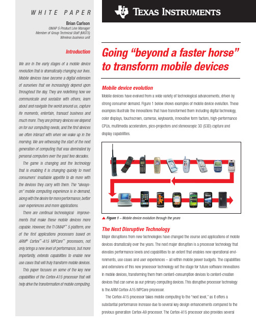
Android is a trademark of Google Inc. Use of this trademark is subject to Google Permissions.Agendan Brief overview of Mentor Graphicsn Overview of Automotive Embedded Solutions n Detailed discussion on AUTOSAR Solutionsn Q & An Current projects & Next stepsMentor GraphicsnElectronic design automation (EDA)industry pioneer founded in 1981nGlobal innovator ofadvanced design solutions from components to systemsn86 Offices and R&D centers worldwide nFY ’15 revenueapproximately $1.24BCritical design software used to create the world ’selectronic systemsMentor Graphics Global PresenceUnited StatesCanadaIreland United Kingdom NetherlandsGermany Denmark Sweden FinlandPoland Armenia Russia China KoreaJapanTaiwanSingaporeAustriaItalyHungaryEgyptIsraelPakistan IndiaFranceSpainSwitzerlandChile Morocco5,400 Employees WorldwideNon-U.S. employees represent 60% of baseEngineers Account for ~50% of Employees WorldwideRevenue: non-US 55%; US 45% USGreg HinckleyPresident and COOProduct DivisionsSystem Design (SDD)Design to Silicon (D2S)Emulation (MED)Design Verification Test (DVT)Analog Mixed Signal (AMS)World TradeFinanceLegalHRITMarketingMike EllowUnique Multi-OS Automotive Vendorn Android, AUTOSAR, Linux, Nucleus RTOS n326 automotive focused engineersn Mentor Linux in planned production for >50 million vehicles n Mentor AUTOSAR in >130 Car Models n 21 OEM Customers n37 Tier 1 CustomersSemiconductor,15%Industrial,9%Medical 7%Networking5%Mil-Aero 1%Consumer2%Multi-OSAndroid ●AUTOSAR●Bare metal●Linux●Nucleus RTOSSecure MulticoreFrameworkType 1 Hypervisor ●AMP ●SMP ●TrustZone EnabledToolingSourcery CodeBench ●Analyzer ●AUTOSAR Virtual Prototyping ●Requirements TracingOur Expertise-Infotainment-ECU Software-AUTOSAR, VTP and Tools -ASIL, ISO26262 support-ADAS Platforms -Video Expertise-Driver Information -Safety SolutionsSystem Development Kit (SysDK)n Integrated design kit to rapidly prototype automotive embedded systems for a widerange of applications –IVI, ADAS, digitalclusters etc.n Significantly shorter time-to-market with automotive grade reference platformn Reduced costs through accelerated product developmentn Increased reliability via on-road production proven systemsMentorConnected OS™HardwarePlatformDevelopmentInfrastructureReferenceDocumentationIn-Car ExperienceINFOTAINMENT (IVI)Using a Reference PlatformnUsing a reference platform will reduce time-to-SOPFeature ReadyTimeOS SelectionLibrary development Graphics / AudioLayersApplication IntegrationIntegration and TestPerformance TestingBoot Code OptimizationKernel Optimization SOP DeadlineOS SelectionResearch LearningTime to SOP –with reference platformnUsing a reference platform will reduce time-to-SOPFeature ReadyTimeApplication IntegrationIntegration and TestPerformance TuningSOP ReadyReference PlatformTypical Infotainment StackStandards Based Reference Platform SOC ChoiceApplicationsHMI OEM Control Tier 1 & OEM ControlProduction-Ready Embedded PlatformBootLoaderKernelMiddleware IndependentSUPER BSP & OPTstack®AccelerateSOC PlatformsJacinto 5Jacinto 6i.MX 61. 2. 3.2. 3.Supportfor new platforms1.Automotive Base PlatformIBC (Initial Boot Code)Automotive FastBoot Bootloader ¨Power-Fail-Safe UpdateLinux OSAutomotive BSP ¨Silicon Vendor Communication ¨Optimization/FastBoot ¨Configuration ¨MaintenanceAutomotiveSystem ServicesAutomotive Audio Automotive VisualsSystem Architecture Design ReviewsProfessional Engineering+ToolsSystem Libraries Board PeripheralsSourcery CodeBench YoctoC o n n e c t e d O S ™Name Fully-Programmable Cluster Connected Cluster Hybrid-Cluster + Head unitDescription High performance clusterwith a modern look and feel Cluster capable of displayingdata from an external inputConsolidated solution ofcluster and Head unit with 1or 2 displays + HUDKey Features Safety critical RTOSCar network integration Displaying incoming contentfrom external sources (e.g.decoded video from CEdevices or other ECUs)Multi-display supportOS separationShared graphics support withHW accelerationDisplayExtension toHUDüüüPricing$$$$$$Mentor’s RTOS: NucleusMost deployed RTOS; over 3 billion units shippedIntegrated Power Management–Industry First RTOS SolutionAdvanced Graphics and SecurityMentor Mixed-Criticality SolutionSafe Graphics RenderCertifiedSafe Instrument LogicSafe Graphics Driver•Graphics Planes blended in hardware,•Managed by safe driverDraws contentto separate graphics plane managed by safe driverExample Implementation-TI Jacinto 6-Fastboot-CAN andEthernetLinux-basedADAS PlatformsAcoustic Vehicle Alerting System (AVAS)n Complete product delivery of pedestrian warning car sound systemn Spans project architecture, product development, industrialization, product qualification and certificationRegulation for EV and EHVs Effective 2013“the sound to be generated by the AVAS should be a continuous sound that providesinformation to the pedestrians and vulnerable road users of a vehicle in operation. Thesound should be easily indicative of vehicle behavior and should sound similar to thesound of a vehicle of the same category equipped with an internal combustion engine.“Reduced CostRemoval of passive noise dampening materials Accelerated Time-to-Market In-car tuning in days vs. weeksBroadband ANC Engine & Road Noise Cancellation Optimized for Vehicle AcousticsRefined In-Car ExperienceActive Noise ControlOverviewANC Demo Vehicle: Ford Lincoln MKZ HybridMentor’s AUTOSAR Solutionsn VSx Design Tools—Network and connectivity synthesis—Timing and Performance Analysis—Virtual platforms and simulation—Automated AUTOSAR ECU Configurationn VSTAR Run-Time Software—Complete AUTOSAR 4.x compliant stack—Support for OEM specific modules—Connectivity: CAN, LIN, FlexRay, Ethernet—ISO26262 Safety Certifications, Multi-Coren Professional Services—Implementation, migration from legacy solutions—Training, on-site project support—Integration, Boot-Loader development, DiagnosticsMentor ’s AUTOSAR ECU Design SuiteBidirectional OEM-Tier 1 Design Cycle CollaborationOEMArchitectural Design & ECU SpecificationTier 1ECU Design &ImplementationAUTOSAR overviewn AUTOSAR is AUT omotive O pen S ystem AR chitecture.n It is an open standard for the car manufacturers and their suppliers for designing the automotive software and electronic architectures.n AUTOSAR helps in bringing down the overall cost of a vehicle platform by enabling reuse of functionality and software.Industry Trends –Solutionn Reuse of functions andsoftwaren Fast integration of newtechnologies—Hybrid & Electrification—Advanced Driver Information n Scalable architectures—From compact to luxury—Flexible and extendablen Increased connections of functions and data exchangen Standardization n Domain architecturesn AUTOSAR and GENIVIn Integrated E/E development solutionsTrends/Requirements SolutionReuse of Features and SW on different vehiclesAdvanced Driver Info. Engine ControlAudio SystemClimate ControlActive Cruise ControlFeatureSoftware ComponentsSWC 1SWC 2SWC 3SWC 1SWC 2SWC 3SWC 1SWC 2SWC 3SWC 1SWC 2SWC 3SWC 1SWC 2SWC 3Architecture Evolutionn Developed for specific car models –not scalable and reusable n Software download to long for production and servicenSoftware with complex dependencies –everything is networked witheverything else.199820062012Source:Designed around You -Volvo ‘s all new EE Architecture and Development ProcessDr. Thomas M. M üller, Vice President, Electrical & Electronic Systems Engineering,Volvo Car Group Automobil Elektronik Kongress, July 2013, Ludwigsburg, GermanyDomain Architecture: Scalable ReuseInfotainmentCombiMulti-mediaHeads UpBodyPower WindowClimate Control Climate Seat PowertrainEngine ControlHybridInverter BEVCompactMediumLuxuryB a c k b o n e F l e x R a y /E t h e r n e tChassisABSActive SuspensionRear SteeringChassis CANSafetySeat BeltAirbags Forward RadarSafety CANAUTOSAR Activity: FY14 and beyondnAUTOSAR 3.x is decliningnAUTOSAR 4.x is growing significantly nAUTOSAR is a world-wide successnNew ECU design starts to drive the AUTOSAR 4.x demandECU4.X ECU Design Starts 2013 –2016Source: Industry events and meeting, MGC estimates0204060801001201401601802009201120132015AR 4.0AR 3.xMGC’s AUTOSAR backgroundn1998: Volcano Automotive was founded.n2000: Founding Member of the LIN consortium.n2003: AUTOSAR Consortium Startedn2004: Joined AUTOSAR as Premium Membern2005: Mentor Graphics acquired Volcano Automotiven2006: VSx product line started (Version 3.x)n2008: Won the first customer -BMWn2012: Released first complete AUTOSAR 4.0.3 solution (Design to implementation) and won the first AR 4.0.3 production project at Volvo Cars (SOP 2014)n2012/13 Majority of AR 4.0.3 ECU production projects capturedØCurrently >100 people in development, application, service and support worldwideØ400 Person Years invested in AUTOSAR solutionIdeal Solutionn Full Flow Coverage—Design –SW and System authoring—Implementation: SWC, BSW and ECU config—Test –PC, Emulation, ECUn Integrated and Modular—Full coverage without interface problems—Works with all different other tools supporting AUTOSAR (e.g. MATLAB/Simulink)n Standards Based—100% AUTOSAR compliant—Eclipse, ARTOP, SPHINX, Genivin Services—Competent AUTOSAR know-how to finishproject in time and available world wide —Training, coaching, integration, migrationn ISO26262—Functional safety from ASIL A -DOSLCMGC ’s AUTOSAR solution¨Full SolutionØAvailable off the shelf ØSeveral existing OEM and T1 customers for 4.0.x ¨Open, Modular and Integrated¨ISO26262 SupportAUTOSAR VSx Tools Overviewn System and ECU Designn SWC, CSWC and deployment n RTE, OS, COMmunication(LIN, CAN, FlexRay) stackValidation andnE/E Architecture &E/E Architecture ExplorationSWC, CSWC and deploymentAUTOSAR and EAST-ADL basedVSx Tool PlatformVSASystem Design,AUTOSAR authoringVSBECU Design BSW Configuration and BuilderVSIVirtual ValidationAPICustomer Plugin, ScriptingVSx InfrastructureAUTOSAR MetaModel Handling (ARTOP and SPHINX based)VSA COMNetwork Design LIN, CAN, FRAUTOSAR Layered Architecture: ECU Software DevelopmentBSWCommunication LIN, CAN, FREthernetCommunication StackMicrocontroller HWMCALAUTOSAR FlowECU 1ECU 2SWC 1SWC 2SWC 3Output: System DescriptionSystem Design and Communication Output: ECU ExtractECU 1SWC 1SWC 3Extract Output: ECU Configuration DescriptionECU 1SWC 1SWC 3ECU ConfigurationRTEBSWSWC 1SWC 2SWC 3VFBOutput: SWC DescriptionSWC DesignV e h i c l e V i e wE C U V i e wAUTOSARExchange (arxml)Android is a trademark of Google Inc. Use of this trademark is subject to Google Permissions.Model Creation with Round-Trip WorkflowSkeleton Simulink ModelSimulink Data Objectsarxml import SW-Cdesign internal behaviormerge SW-C backc, harxmlgenerate codevalidate modelStep 1Step 2Step 3Step 4Step 5Completed Simulink Model*.mVSAVSA –COM Designer: AUTOSAR Network DesignnCreate communication matrix for CAN,LIN, FlexRay systemsn Capture signal timing requirementsnPack signals into frames and schedule frames on networkn Route gatewayed signalsnAnalyze signals communication delays and network utilization ECU 1ECU 2SWC 1SWC 2SWC 3Signal ATiming requirement: 100ms ECU 1ECU 2SWC 1SWC 2SWC 3ID DataFrame 1Period 50ms Signal A Timing AnalysisSignal Req Com Delay -Signal A 100 67-Signal B 150 77-Signal C 15067-Signal D 200 77SWC CompositionFlexRay ScheduleFrame PackerConfiguration SetupAndroid is a trademark of Google Inc. Use of this trademark is subject to Google Permissions.VSB BSW Configuration EditornVSB process developed according to AUTOSAR methodologynVSB process supports an iterative development where the ECU extract can be updated and changes merged into existing configurationnVSB process supports parallel development where several users may work with different aspects of the same configurationSWC 1SWC 3RTEBSWOSConfiguring OSConfigure 1000 Communication ParametersE c u C o n f i g u r a t i o n n a v i g a t o rE c u C o n f i g u r a t i o n l o g i c a l v i e wAdvanced editor (FlexRay job list)Service and IOHW view Property editorECU ConfigurationMGC VSTAR BSW 4.0.x stackApplication LayerSWC 1SWC 3RTE BSWAndroid is a trademark of Google Inc. Use of this trademark is subject to Google Permissions.VSI: Virtual Systems Integratorn Execution environment for AUTOSAR Systems on the desktop n Early validation of SW functionality on virtual ECU and BSW n Migration and debug for legacy applications into AUTOSAR nFull debug and interactive validation at all relevant levels ofsoftware system, OS task or executing codeMy_mod.cinitialbegin clk = 0;#10 clk = 1;forever #50 clk =!clk;end My_mod.c initial begin clk = 0;#10 clk = 1;forever #50 clk =!clk;endRTESWC 1SWC 2SWC 3Software Modeling UML T oolHand CodeModel Based DesignPC HardwareIdeal Solutionn Full Flow Coverage—Design –SW and System authoring—Implementation: SWC, BSW and ECU config—Test –PC, Emulation, ECUn Integrated and Modular—Full coverage without interface problems—Works with all different other tools supporting AUTOSAR (e.g. MATLAB/Simulink)n Standards Based—100% AUTOSAR compliant—Eclipse, ARTOP, SPHINX, Genivin Services—Competent AUTOSAR know-how to finishproject in time and available world wide —Training, coaching, integration, migrationn ISO26262—Functional safety from ASIL A -D P P P P PMGC’s Customer Basen40 AR 4.0.3 projects.n14 in VCC (Delphi, Robert Bosch, Denso, BHTC, HUF, Actia, ELTEC, Siemens, Alpine, Futjisu etc.), 14 in BMW (incl. VAP, Robert Bosch)n First sourced ECUs from GM Global B (Denso) and JLR (Borg Warner)n Strategic partnership with Delphi for all AUTOSAR ECUs n Additional ECUs at SAIC, LG。
美行科技路帮-你要的限行数据解决方案2020

1、全国覆盖
24个省95个城市、173个区县限行查询数据,多达33个字段限行规则调用
(数据不断更新中……)
数据调取最小范围到区/县 限行区域矢量图清晰获取
Copyright @ 2019 MXNAVI. All rights reserved.
有保障
Copyright @ 2019 MXNAVI. All rights reserved.
2020年 路帮发展
在千万级下载量车主服务类APP合作考验下,路帮服务响应及时且高效 货车限行数据开发中…
LOOPON 合作案例—千万级下载量车主服务类APP
限行数据由路帮网提供
Copyright @ 2019 MXNAVI. All rights reserved.
你要的限行数据解决方案
沈阳美行科技有限公司
对于广大车主来说,限行信息获取已经成为刚需
尾号限行一直是一个非常态的交通管制方式。目前中国已经有近百个城市推行了限行管制措施, 且各地限行措施不一,有日期限行、尾号限行、单双号限行、特殊号牌限行、开四停四、所有号 牌区域限行等等。
Copyright @ 2019 MXNAVI. All rights reserved.
30
67
18
可结合美行导航定制开发
Copyright @ 2019 MXNAVI. All rights reserved.
16
பைடு நூலகம்
LOOPON 数据演示端-WEB端
网址:
Copyright @ 2019 MXNAVI. All rights reserved.
17
2016
2017
ADRV9026四通道宽带RF接收器平台商品介绍说明书

VISIT ADRV9026Quad-Channel, Wideband RF Transceiver Platform200 MHz Bandwidth Integrated Radio Transceiver SolutionApplications►Macro base stations ►Massive MIMO►Small cell designs1See page 3 for future enhancements in the ADRV902x family roadmapSmallest Size, Lowest Power Transceiver Solution for Base Transceiver Stations (BTS )►Smallest size reduces footprint and enhances form factor flexibility►50% power consumption reduction over previous generation ADRV9009 for increased radio density►Enables ORAN small cell designs with lowest system power and costHighly Integrated, High Performance Software-Defined Radio►2× integration over ADRV9009►Supports up to 200 MHz bandwidth and covers all bands from 650 MHz to 6 GHz 1Common Platform Design for 3G/4G/5G Reduces Complexity, Development Costs, and Time to Market►Single-chip FDD/TDD solution simplifies hardware and software development ►Common API across multiple applications►Reduces product development cycles for band and power variants►Enables modular architecture for scalable radio solutionsADRV9026 Quad-Channel, Wideband RF Transceiver Platform RF SynthRF Synth ORX1/ORX2TX 1TX 2RX10°90°RX2RX3+RX3–RX4+RX4–RX1+RX1–RX2+RX2–TX3+TX3–TX4+TX4–TX1+TX1–TX2+TX2–ORX3+ORX3–ORX4+ORX4–ORX2+ORX2–ORX1+RF SynthLO 1LO 2GPIO AuxADC AuxDACGPINT1JESD204B/C Serial InterfaceClock GenerationandSynchronizationDEVCLK±SYSREF±LO 2LO 1LO 2LO 1RX3, RX4, TX3, TX4, ORX 3/ORX4RX1, RX2, TX1, TX2, ORX 1/ORX2pFIR,LO Leakage,QEC, Tuning,InterpolationGPIO_ANA_n AUXADC_nSPI_CLKSPI_EN SPI_DO SPI_DIORXn_EN TXn_EN ORXn_EN VDDA_1P8VDDA_1P3VDDA_1P0VDIG_1P0EXT_LO1±EXT_LO2±PWR MGMTGPINT2RESET TESTSERDOUTA±SYNCIN1±SYNCIN2±SYNCIN3±SERDINA±SERDINB±SERDINC±SERDIND±LO 3LO 3SYNCOUT1±SYNCOUT2±8419VIF444SERDOUTB±SERDOUTC±SERDOUTD±MicroprocessorADCADCDACDACADCADCDecimation,pFIR,DC Offset,QEC,Tuning,OverloadDecimation,pFIR, AGC,DC Offset,QECTuning RSSI,OverloadControl InterfaceSPI Port0°90°0°90°2ADRV9026 Quad-Channel, Wideband RF Transceiver Platform3Visit ADRV9026 Overview►Four differential transmitters ►Four differential receivers►Two observation receivers with two inputs each ►Center frequency: 650 MHz to 6000 MHz ►Maximum receiver bandwidth: 200 MHz ►Maximum transmitter bandwidth: 200 MHz►Maximum transmitter synthesis bandwidth: 450 MHz►Maximum observation receiver bandwidth: 450 MHz►Fully integrated independent fractional-N radio frequency synthesizers ►Fully integrated clock synthesizer►Multichip phase synchronization for all local oscillators and baseband clocks ►Support of TDD/FDD 3G/4G/5G applications►16 Gbps JESD204B/C digital interfaceSee roadmap below for future enhancementsADRV9026 Family RoadmapEnhanced features and functions will be added to the ADRV9026 over time, including:►25 Gbps SERDES support►Extending LO frequency range down to 75 MHz►Support for an external LO►Filter Wizard to generate custom profilesAn enhanced version from the ADRV902x family will be released in 2020 with integrated DPD and CFR, reducing FPGA requirements, as well as lowering total system power and cost.RadioVerse Ecosystem and PartnershipsRadioVerse ® is a design and technology ecosystem for advanced radio design and development. We offer market-leading integrated transceiver technology, software tools, evaluation and prototyping platforms, a range of reference designs, and radio solutions. RadioVerse is building up a global partnership network to provide customers all levels of design support. ADRV9026’s partner network and reference design ecosystem will be launched on /radioverse in 2020.Evaluation SystemThe evaluation system comprises an FPGA carrier board ADS9-V2EBZ and a radio daughtercard, coming with two frequency bands of matching: –HB for 2.8 GHz to 6 GHz and –MB for 650 MHz to 2.8 GHz. Compatible evaluation software is provided for download, including API library, Windows GUI, and a binary image for FPGA configuration.Radio CardsCarrier BoardsSoftware and DriverE v a l u a t i o n S y s t e m►ADRV902X-HB/PCBZ (for 2.8 GHz to 6 GHz )►ADRV902X-MB/PCBZ (for 650 MHz to 2.8 GHz )►ADS9-V2EBZ(FPGA motherboard with Xilinx ® UltraScale+™)►Operating system-agnostic API source in ANSI C►Windows GUI for transceiver configuration and data capture►Binary image for FPGA configurationFor regional headquarters, sales, and distributors orto contact customer service and technical support, visit /contact.Ask our ADI technology experts tough questions, browse FAQs, or join a conversation at the EngineerZone Online Support Community. Visit .©2019 Analog Devices, Inc. All rights reserved. Trademarks and registered trademarks are the property of their respective owners.PH21775-11/19(A)VISIT 。
Realtek WiFi Roadmap

Realtek WLAN Update Dec, 2011Q1 Q2 Q3 Q42011Q1 Q2 Q3 Q42012Q1 Q2 Q3 Q42013Value (SB 1x1)Position (SB 2x2 & 1x1 Combo)Performance (DB & 11ac)RTL8188CE/CE-VL -802.11n 1T1R SB -SWR/LDO regulatorRTL8188EE-802.11n 1T1R SB -SWR/LDO regulator -LTR/OBFFRTL8723AE-802.11n 1T1R SB -BT2.1/3.0/4.0 LE -SWR/LDO regulatorRTL8192DE-802.11n 2T2R DB -DB concurrentRTL8812AE-802.11ac(pre) 2T2R DB -80MHz BW(650Mbps PHY)RTL8813BE-802.11ac 3T3R DB -160MHz BWRTL8192CE-802.11n 2T2R SB -SWR regulatorRTL8811AE-802.11ac 1T1R DB-80MHz BW(433.3Mbps PHY)RTL8723BE-802.11n 1T1R SB -BT2.1/3.0/4.0 LE -FM Tx/Rx-SWR/LDO regulatorRTL8821AE-802.11ac 1T1R DB + BT2.1/3.0/4.0 LE -80MHz BW(433.3Mbps PHY)RTL8822AE-802.11ac(pre) 2T2R DB+ BT2.1/3.0/4.0 LE -80MHz BW(650Mbps PHY)Q1 Q2 Q3 Q42011Q1 Q2 Q3 Q42012Q1 Q2 Q3 Q42013RTL8188EU-802.11n 1T1R SB -SWR/LDO regulator -LPMRTL8723AU-802.11n 1T1R SB -BT2.1/3.0/4.0 LE -SWR/LDO regulator -USB multi-functions RTL8192DU-802.11n 2T2R DB -DB concurrentRTL8812AU-802.11ac(pre) 2T2R DB -80MHz BW(650Mbps PHY)-USB3.0RTL8813AU-802.11ac 3T3R DB -160MHz BW -USB3.0RTL8192CURTL8192CE-VAU -802.11n 2T2R SBRTL8188CUS/CTV RTL8188CE-VAU -802.11n 1T1R SB-SWR/LDO Regulator Value (SB 1x1)Position (SB 2x2 & 1x1 Combo)Performance (DB & 11ac)RTL8723BU-802.11n 1T1R SB -BT2.1/3.0/4.0 LE -FM Tx/Rx-USB multi-functionsRTL8811AU-802.11ac 1T1R DB-80MHz BW(433.3Mbps PHY)RTL8821AU-802.11ac 1T1R DB + BT2.1/3.0/4.0 LE -80MHz BW(433.3Mbps PHY)Q1 Q2 Q3 Q42011Q1 Q2 Q3 Q42012Q1 Q2 Q3 Q42013RTL8189ES-802.11n 1T1R SB -SWR/LDO regulator -LTRRTL8723AS-802.11n 1T1R SB -BT2.1/3.0/4.0 LE -SWR/LDO regulator RTL8712S-802.11n 1T2R SB -SWR regulatorRTL8811AS-802.11ac 1T1R DBRTL8723BS-802.11n 1T1R SB -BT2.1/3.0/4.0 LE -FM Tx/RxRTL8189CS-802.11n 1T1R SB--pin-to-pin with RTL8723ASValue (SB 1x1)Position (SB 2x2 & 1x1 Combo)Performance (DB & 11ac)RTL8821AS-802.11ac 1T1R DB -BT2.1/3.0/4.0 LERTL8831AS-802.11ac 1T1R DB -BT2.1/3.0/4.0 LE -FM Tx/RxRTL8851AS-802.11ac 1T1R DB -BT2.1/3.0/4.0 LE -FM Tx/Rx -GPSRTL8188CUS Chipset Solution•Package: 46 Pin QFN•Process: 65nm•Single Chip Solution integrating CMOS MAC, Baseband, RF, EEPROM•Operating at 2.4GHz ISM Frequency Band •802.11b/g/n 1T1R MiMo Solution•USB2.0 Interface•Support for Realtek GreenWLANConfidential for nVidiaConfidential for nVidiaLow rBOM + Small footprint –USB (1x1)68QFN 76QFN 46QFN Package FootprintExternal Front EndExternal EEPROM Built ‐in 3.3V LDO4.5x6.5mmNO NO YES (SW Reg.)Realtek 1x1 RTL8188CUS9x9mmPA x 1NO YES (Linear)Ra 1x1RT30709x9mmNO YES NOATHR 1x1AR9271Confidential for nVidiaRalink Atheros RTL8188CUSRTL8188SU RT3070Netgear WN111v2Unassociated idle 91.2/20(*)140190/102(*)210Associated idle 92.6/45(*)143190/67.38(*)240Radio off 18.93833N/A Card Disable 1.36 1.9 3.2 2.4Suspend 1.36 1.9 3.2 2.4Continuous Rx 105@87.4Mbps 159@91Mbps 230@83Mbps 273@109Mbps Continuous Tx 129@85Mbps 130@102Mbps240@80Mbps225@96MbpsPS1: (*) enable power saving mode PS2: AP using DIR ‐655Unit: mARealtekBetter Thermal experience ‐USB (1x1)Realtek 42 vs Ralink 62Lower power consumption would have lower case temperature and should be more stable.RTL8188CUS USB Software Support•Support for Linux Kernel 2.4 and 2.6•Support for Android up to Ver.2.3 now •XP/Linux Version of MP tool•Support for Win XP driver for testing•Wi‐Fi Direct•Security support for WEP, WPA, WPA2, WPSConfidential for nVidiaRTK Wi‐Fi on Tablet/MID ApplicationsPlatform Realtek Wi-Fi Solution Freescale i.MX51/ Android 2.1/2.2/2.3RTL8188CUS/RTL8712SDIO nVIDIA/Android 2.1/2.2RTL8188CUS/RTL8712 SDIO Marvell 166 (ARM based)/Android2.1/2.2RTL8188CUSTelechips TCC89xx/Android 2.1/2.2/2.3RTL8188CUS/RTL8712SDIO InfoTM IC/Android 2.1/2.2RTL8188CUS/RTL8712SDIOZT-N180A ARM 11 (InfoTM)/Android 2.1/2.2RTL8188CUSRockchip 2818/Android 2.1/2.2/2.3RTL8188CUSIngenic jz4760/Android 1.6/2.2/2.3RTL8188CUSSamsung S5PV210/Android2.2RTL8188CUSWonderMedia WM8505/WM8650/Android 2.2/2.3RTL8188CUSWonderMedia WM8505/WM8650/WinCE 6.0RTL8188CUSAmlogic 8726m /Android2.2/2.3RTL8188CUSRenesas/Android 2.2RTL8188CUSJade Tech(X900/Android 1.6RTL8188CUSWW First Sale (RTL8188CUS)http://www.planex.co.jp/product/wireless/gw‐usvalue‐ez2T2R 2.4G2T2R 2.4/5GBroad Selection for USB applicationsCostP e r f o r m a n c e1T1R 2.4G1T1R+BT Combo8188CUS 8192CU 8188SU8192DU8188CUS + BC81T2R 2.4G8191SU8192SU8188CE-VAURTL8188CE‐VAU USB miniCard●Excellent power consumption performance●Least power consumption of USB WLAN in the world●Support selective suspend●Unique power down mode support●Same design as RTL8188CE PCI‐e Minicard●No engineering effort●Same MP environment●More than 120 countries homologation●Valued features for table PC applications●Optional single antenna support●Android supportRTL8188CTV Module –UM88C061.2 layers of PCB Design.2.Single side of component populated.3.Single printing antenna design.4.With dimension of 36 x 18mm.e as stamp type of module to connect to the main board.6.3.3V Input powerUM88C06 ModuleRTL8723AS Reference Design•WLAN, BT single chip–WLAN: 2.4GHz, 802.11b/g/n 1T1R–BT2.1+EDR/BT3.0+HS/BT4.0 LE•I/F: SDIO(WLAN)+UART(BT)•Module instead of HMC–Main board rBoM saving◆PCIe socket saving–Smaller, thinner, less weight for tablet or Netbook◆11x20mm2w/o antenna connector◆11x30mm2w/ antenna connector •Support GreenWLAN TM•Support Wi‐Fi Direct/EZ Sharing/uWiFiRTL8723AS LGA Module20mm10mm30mmModule w/o antenna connector Module w/ antenna connectorFront Side Back SideRTL8723AS LGA Module Application Module on main boardw/ PCB antennaModule on main boardw/ Murata/IPEX antennaconnectorRTL8723As Power Consumption8723ASMode 3.3V Power consumption(mA)TP(Mbps)WIFI Reset0.048N/A Non-Associated0.074N/A Associated Idle0.818N/A Radio off0.074N/A Tx n mode 40MHz130.54545 Rx n mode 40MHz75.23647 Tx n mode 20MHz12643.9 Rx n mode 20MHz7446.1 Tx g mode12026.4 Rx g mode7323 Tx b mode122 5.2 Rx b mode74 5.4RTL8723A Reference Design SummaryBoard TypeForm Factor HMC LGA moduleChipset P/N RTL8723AE RTL8723AE-VAU RTL8723AS RTL8723AS-VAU Interface PCIe+USB USB Multi-Function SDIO+UAR USB Multi-Function Package QFN68QFN68QFN68QFN68PCB Layer2L2L4L4LBoard Size Standard HMC10x20mm2/10x30mm2Sample status ES: Sep'11MP: Dec'11ES: Nov'11MP: Jan'12ES: Dec'11MP: Jan'12ES: Dec'11MP: Jan'12SW alpha Sep'11Nov'11Dec'11Dec'11 SW beta Oct'11Dec'11Jan'12Jan'12 DVT Report Oct'11Dec'11Dec'11Dec'11 HW HDK Sep'11Nov'11Dec'11Nov'11Regulatory Major countries:Oct'11Others: Dec'11Major countries:Oct'11Others: Dec'11Major countries:Feb'12Others: Apr'12Major countries:Feb'12Others: Apr'12Summary(1)RTL8723AE/AE ‐VAU will share the same HDK package with description in different sheetsa)Same homologationb)Only 3 component difference (Cx2 & Rx1) between RTL8723AE/AE ‐VAM & RTL8723AE ‐VAU(2)RTL8723AS/AS ‐VAU share the same HDK package with description in different sheets (3)RTL8723AE ‐VAS is only for reference design development on nVidia platformEnd WNIC Products WLANBTPCI ‐EUSB SDIOPCI ‐EUSBUARTRTL8723AE (1)●●RTL8723AE ‐VAM (1)●●RTL8723AE ‐VAU (1)●●RTL8723AS (2)●●RTL8723AS ‐VAU (2)●●RTL8723AE ‐VAS (3)●●‐11‐Copyright ©2011Realtek Semiconductor Corp.。
海哥尔德电子产品简介说明书

APRIL 2013Quick-Refere nce GuideLAPTOP, DESKTO P AND VIDEO STORAGE DRIVESSeagate Partner Program MembersVisit the Sales Tools section to access the latestproduct roadmap, end-of-life schedule and product information. DistributorsEMEA SPP Support00-800-6890-8282US Sales Support1-800-SEAGATE or 1-405-324-4700Visit for more information or call 1-800-SEAGATE (1-800-732-4283) © 2013 Seagate Technology LLC. All rights reserved. Printed in USA. Seagate, Seagate Technology and the Wave logo are registered trademarks of Seagate Technology LLC in the United States and/or other countries. Barracuda, G-Force Protection, Momentus, Pipeline HD, SmartAlign and SV35 Series are either trademarks or registered trademarks of Seagate Technology LLC or one of its affiliated companies in the United States and/or other countries. The FIPS logo is a certification mark of NIST, which does not imply product endorsement by NIST, the U.S., or Canadian governments. All other trademarks or registered trademarks are the property of their respective owners. When referring to drive capacity, one gigabyte, or GB, equals one billion bytes and one terabyte, or TB, equals one trillion bytes. Your computer’s operating system may use a different standard of measurement and report a lower capacity. In addition, some of the listed capacity is used for formatting and other functions, and thus will not be available for data storage. Actual data rates may vary depending on operating environment and other factors. The export or re-export of hardware or software containing encryption may be regulated by the US Department of Commerce, Bureau of Industry and Security (for more information go to ). Seagate reserves the right to change, without notice, product offerings or specifications. QR502.15-1304GB, April 2013APRIL 2013Quick-Reference GuideLAPTOP, DESKTOP AND VIDEO STORAGE DRIVESNew Seagate Model Number KeyDesktop, laptop and video storageST 500 DX 001BRANdCAPACiTySegMeNTATTRiBuTeS2 letters ST= Seagate MX= Maxtor2 to 4 digits 80 = 80GB 500 = 500GB 1500 = 1,500GB Capacities>9,999GB: 10 = 10TB 15 = 15TB2 lettersDX = Desktop Premium DM = Mainstream DL = Entry LevelLX = Laptop Premium LM = Laptop Mainstream LT = Laptop Thin VX = Surveillance VM = DVR VT = DVR Thin3 digits, non-intelligent Varies for:Z-height Form Factor RPM Cache Interface SED, FIPS Drop Sensor Interface SpeedView a brief training presentation on how our model numbering format has changed at /seagate/ModelNumber 1 One gigabyte, or GB, equals one billion bytes; and one terabyte, or TB, equals one trillion bytes when referring to drive capacity.2See FIPS 140-2 Level 2 Certificate at /groups/STM/cmvp/documents/140-1/1401vend.htm.37mm z-height expanded to 9.5mm enables compatibility with standard laptop chassis.4Advanced Format 4K sector drive with SmartAlign ™ technology resolves misalignment conditions.5Seagate makes this drive in both 4K and 512-byte sectors. SmartAlign technology is included on 4K sector drives. Both drives are functionally and physically equivalent.6Formerly Barracuda ®drive。
EICAD3.0说明

6.45.4道路模型实体................................................................................................................9
3.22.2MeshEditor程序支持快捷、高效的模型编辑..............................................................6
3.32.3支持道路设计过程中实时剖切....................................................................................6
EICAD简介
EICAD简介
1.目录................................................................................................................................................2
EICAD 3.0.0在原有2.99版的改进型导线法、积木法和扩展模式法的基础上,吸收了国
内外道路、轨道和管线等领域新的线路平面设计理论和实现方法。大大强化了全过程动
态拖动设计功能;实现了快捷、实时的实体联动。
在布设各种复杂立交、在众多高压线塔、高架桥桥墩等障碍之间的穿行、在山
Simplex

Individually addressable manual fire alarm stations for releasing applications with:∙Power and data supplied via IDNet or MAPNET II addressable communications using a single wire pair∙Operation that complies with ADA requirements∙Visible LED indicator that flashes duringcommunications and is on steady when the station hasbeen activated∙Pull lever that protrudes when alarmed∙Break-rod supplied (use is optional)∙Dual action push and pull operation∙Label kit provides for six varieties of releasing applications (ordered separately)Compatible with the following Simplex® Releasing System control panels equipped with either IDNet or MAPNET II communications:∙Model Series 4100ES, 4010ES, and 4010∙Installed 4100, 4120, and 4020 systemsCompact construction:∙Electronics module enclosure minimizes dust infiltration ∙Allows mounting in standard electrical boxes∙Screw terminals for wiring connectionsTamper resistant reset key lock∙Locks are keyed the same as Simplex fire alarm cabinets Multiple mounting options:∙Surface or semi-flush with standard boxes or matching Simplex boxes∙Flush mount adapter kit∙Adapters are available for retrofitting to commonly available existing boxesUL listed to Standard 38These 4099 series addressable manual stations combinethe familiar Simplex housing with a compact communication module providing easy installation for releasing applications. The integral individual addressable module (IAM) monitors status and communicates changes to the connected control panel via MAPNET II or IDNet communications wiring.A blank area on the front of the station allows the selection of a label to match the specific releasing application (label kit is ordered separately). (Refer to data sheet S4099-0005 for standard Simplex addressable manual stations.)* This product has been approved by the California State Fire Marshal (CSFM) pursuant to Section 13144.1 of the California Health and Safety Code. See CSFM Listing 7150-0026:224 for allowable values and/or conditions concerning material presented in this document. Additional listings may be applicable; contact your local Simplex product supplier for the latest status. Listings and approvals under Simplex Time Recorder Co. are the property of Tyco Safety Products Westminster.4099-9015 Addressable Manual Station for Releasing Applications (with Manual Release label from4099-9802 Label Kit)Label Kit4099-9802Activation requires that a spring loaded interference plate (marked PUSH) be pushed back to access the station pull lever with a firm downward pull that activates the alarm switch. Completing the action breaks an internal plastic break-rod (visible below the pull lever, use is optional). The use of a break-rod can be a deterrent to vandalism without interfering with the minimum pull requirements needed for easy activation. The pull lever latches into the alarm position and remains extended out of the housing to provide a visible indication.Station reset requires the use of a key to reset the manual station lever and deactivate the alarm switch. (If the break-rod is used, it must be replaced.)Station testing is performed by physical activation of the pull lever. Electrical testing can be also performed by unlocking the station housing to activate the alarm switch.Releasing System PeripheralsUL, ULC, CSFM Listed;IDNet or MAPNET II Communicating Devices; FM Approved *Addressable Manual Stations for Releasing ApplicationsAddressable Manual StationsModelDescription4099-9015 Double action, Push operation, Addressable manual station; red housing with white letters and white pulllever; requires label kit 4099-98024099-9802Label kit, white lettering on red background; select the label required for the specific releasing application; types include: Clean Agent, Extinguishing, Carbon Dioxide, Foam System, Sprinkler, and ManualAccessoriesModelDescriptionReference2975-9178 Surface mount steel box, redRefer to page 3 for dimensions 2975-9022 Cast aluminum surface mount box, red2099-9813 Semi-flush trim plate for double gang switch box, red Typically for retrofit, refer to page 4 2099-9814 Surface trim plate for Wiremold box V5744-2, red 2099-9819 Flush mount adapter kit, black Refer to page 4 for details2099-9820Flush mount adapter kit, beige2099-9804 Replacement break-rodPower and Communications IDNet or MAPNET II communications, 1 address per station, up to 2500 ft (762 m) from fire alarm control panel, up to 10,000 ft (3048 m) total wiring distance (including T-Taps)Address Means Dipswitch, 8 positionWire ConnectionsScrew terminal for in/out wiring, for 18 to 14 AWG wire (0.82 mm 2 to 2.08 mm 2)UL Listed Temperature Range 32° to 120° F (0° to 49° C) intended for indoor operation Humidity Range Up to 93% RH at 100° F (38° F) Housing Color Red with white raised letteringMaterialHousing and pull lever are Lexan polycarbonate or equal Pull Lever ColorWhite with red raised letteringHousing Dimensions 5” H x 3 ¾” W x 1” D (127 mm x 95 mm x 25 mm) Installation Instructions579-11354" (102 mm) square box, 2-1/8" (54 mm) minimum 4" Square Box MountSemi-Flush Mount Side ViewSingle Gang Box MountSingle gang box, 2-1/2" deepPreferred Mounting. For surface mounting of theseaddressable manual stations, the preferred electrical boxes are shown in the illustration to the right.Additional MountingReference. Refer to page 4 for Wiremold box mounting compatibility.2975-9178 Box5-3/16" H x 4" W x 2-3/16" D (132 mm x 102 mm x 56 mm)Knockouts located top and bottom2975-9022 Cast Box 5" H x 3-7/8" W x 2-3/16" D (127 mm x 98 mm x 56 mm)4099-9015 Addressable Manual StationFor retrofit and new installations, additional compatible mounting boxes and the required adapter plates are shown in the illustration to the right.Front ViewFlush mount adapter kit Side ViewTyco Fire Protection Products • Westminster, MA • 01441-0001 • USAS4099-0006 11/2014TYCO, SIMPLEX, and the product names listed in this material are marks and/or registered marks. Unauthorized use is strictly prohibited. Lexan is a trademark of the General Electric Co. Wiremold is a trademark of the Wiremold Company.。
路路AI-智能路面管理方案说明书

An easier route:5 ways AI improvesroad asset managementTraditional human assessment Drive slowly to detect and document RoadAI Full driving speed; inspector is free to carry out other tasksConducting inspections with two trained personnel per vehicle isa common method of assessing road conditions. This approachlimits how much data inspectors can gather and record whilethey're driving the route. With RoadAI, only one person is requiredin the vehicle, traveling at normal speed. The driver is free to focuson driving.Traditional human assessmentTakes weeks to get data in usable format RoadAI Immediate; data gathered and shared in real timeAfter driving long distances to assess the roads and recordconditions, it takes time to enter the data in a database andextract it in a usable format. RoadAI gathers data in realtime during drives; the data can be uploaded and sharedright away. Once data is gathered, it can be uploaded andanalyzed automatically.Road maintenance is traditionally time- and resource-intensive. From potholes to road signs, the challenge for engineers is to manage a dynamic environment that covers hundreds or even thousands of miles.Artificial intelligence (AI) is helping road maintenance organizations improve their planned and reactive road maintenance strategies. RoadAI provides a quick, complete, objective analysis of pavement conditions through an automated road survey methodology. The end result is a fast and cost-effective means of analyzing road conditions, which makes it possible to repair roads faster and keep them safer.Here are five ways AI improves road asset management.Inspection speed 1.Data availability2.Traditional human assessment Broad and nonspecific RoadAI Comprehensive, automated, used in short- and long-termHuman recording processes tend to cluster defects into broader categories like structural edge or wearing course defects, so the end analysis is more general. Highly detailed video data collection, categorization and analysis are all performed automatically with RoadAI. Traditional human assessment Trained inspectors are neededRoadAI Non-experts can complete inspectionsRoad condition assessment requires trained and experienced personnel who can spot defects in pavement, road signs and other assets. Collecting data is easy with RoadAI — place the phone in a vehicle and start driving. No specialized training is necessary.3.4.Vaisala is here to helpFrom sensors to systems and digital services, Vaisala gives road stakeholders unrivaled road network visibility anddecision support — so everyone can keep moving toward better, more insightful ways of operating. We are recognized experts in transportation, and we continue to channel our curiosity into new ways of making roadways safer and more efficient than ever — as reflected in our guiding principles:See, understand, decide Move ahead The innovators Mobility and beyond /roadai Scan the code formore information Ref. B212319EN-B ©Vaisala 2022This material is subject to copyright protection, with all copyrights retained by Vaisala and its individual partners. All rights reserved. Any logos and/or product names are trademarks of Vaisala or its individual partners. The reproduction, transfer, distribution or storage of information contained in this brochure in any form without the prior written consent of Vaisala is strictly prohibited. All specifications — technical included — are subject to change without notice.Traditional human assessmentManual and seasonal RoadAI Automated and can be repurposed for other needsTraditional road asset management processes —reactive and planned maintenance plus managingnetwork assets — have relied on manual proceduresat certain times of the year. But automated datacollection makes it possible to collect data every timesomeone is simply driving from one place to another.With a wealth of road data already available, you canfree resources to focus on taking care of your roadsin a proactive manner. This process leads to betterresource management at significant cost savings.Learn more about how to drive improvement in your road maintenance strategies.5.。
roadmap 模板
roadmap 模板IntroductionThe roadmap is a visual representation of a long-term plan that outlines goals and objectives for an organization, team, or project. It is a tool used by companies to communicate their vision and strategy to stakeholders, investors, employees, and customers. A well-defined roadmap enables a company to set goals, prioritize tasks, allocate resources, and stay on track toward achieving its objectives.Section 1: Defining the GoalTo create an effective roadmap, the first step is to define the goal. This involves identifying the purpose of the roadmap, the key stakeholders involved, and the scope of the project. The goal should be clearly stated and aligned with the business strategy.Section 2: Creating the RoadmapOnce the goal is defined, the next step is to create the roadmap. There are several things to consider when creating a roadmap. First, it should clearly outline the objectives, milestones, and timelines for theproject. Second, it should provide a comprehensive overview of the resources required for each project phase. Third, it should include metrics for measuring progress toward achieving the objectives.Section 3: Communicating the RoadmapThe success of a roadmap depends on the effectiveness of its communication. It should be communicated to all relevant stakeholders in a clear and concise manner. The roadmap should be easily accessible, updated regularly, and reviewed with stakeholders to ensure alignment with the business strategy.Section 4: Updating the RoadmapThe roadmap is a living document that should be updated regularly to reflect changes in the business environment. As new information becomes available, the roadmap should be revised to reflect these changes. Any changes to the roadmap should be communicated to stakeholders so they understand the impact on the project timeline, resources, and objectives.ConclusionIn conclusion, a well-defined roadmap is essential for any organization seeking to achieve its long-term goals. It provides a clear path for the organization to follow and can help to ensure that it stays on track toward achieving its objectives. By defining the goal, creating the roadmap, communicating it effectively, and updating it regularly, an organization can use the roadmap to help guide its decision-making and propel its success.。
新唐(Nuvoton) Motor MCU Series

(Mini51) 1組獨立 ADC, 12-bit, 8ch, 760KHz
(M052) 2組獨立 ADC, 12-bit, 16/14-ch, 800KHz
(MT530/MT520)
功能說明
PID+FOC+SVPWM (MT530/MT520)
Yes
2組 QEI (MT530/MT520)
2組comparator (Mini 51/M052) 3組comparator (MT530/MT520) 2組OP Amplifier (MT530/MT520)
更快的弦波及磁場導向運算速度
更快的弦波及磁場導向運算速度
MT630 Cortex-M4F, 84Mhz 256/386KB
32/48KB
Flash-shared
4 x 24-bit
8 chx16-bit
NO 2 sets 3xUART & 2xSPI & 1xI2C & 1xCAN2.0b 8ch ADCA 8ch ADCB 12-bit, 1MKHz
3xComp 2xOP
Current Feedback
新唐 MCU 在電機應用上的特點說明(1)
Mini51/M052/ MT530/MT520 PWM解析度 PWM有互補輸出和 可編程死區
PWM中斷要求
PWM煞車(Brake)
ADC轉換時間
特點規格
16-bit
8-bit Dead time control
Yes
可同步觸發ADC
N79E815 ~ N79E8132
TI OMAP Roadmap
Enhancements
128-bit (vs 64) load/store path 3-inst (vs 2) instruction decode 8-micro-ops (vs 4) issue 64-byte (vs 32) cache line Simultaneous load + store Improved brance prediction: • Higher capacity • Support for indirect branches More out-of-order instructions Optimized level 1 caches Tighter integration with NEON/ VFP Improved memory performance: • Tightly-coupled L2 cache reduces latency • Enhanced auto-prefetch • More requests buffering
Key benefits
In the same process node: • >1.5x single-thread performance • >1.6x floating point and media performance • Improved multiprocessing bandwidth • Improved streaming performance • Advanced system support – Hardware virtualization – Larger memory – System coherency
These enhancements focus on improving the processing throughput and efficiency of the core by supporting wider paths, more parallelism, tighter integration and various optimizations. The details of all these processing enhancements are out of the scope of this paper, and can be found in ARM papers and documentation. This paper will later focus on two new features that will significantly benefit mobile devices and extend the software they can support: hardware virtualization and larger physical address extension. Before addressing these new features, it is important to note the significant boost in performance and improved energy efficiency that the Cortex-A15 process delivers.
MTK 智能机平台介绍

Smartphone Platforms p Roadmap OverviewMar 2011Copyright © MediaTek Inc. All rights reserved.Smartphone Platform RoadmapAll smartphone platforms (from MT6573) can be upgraded to TD-SCDMA/HSPA MT657xPlatform Rel. 6 HSPA 1GHz Cortex A9 FWVGA 30fps Video 8MP ISP 4-in-1 Connectivity ComboMT6573 Platform Rel. 6 HSPA 650 MHz ARM11 FWVGA 30fps Video 8MP ISP 4-in-1 Connectivity ComboMT6516 Platform EDGE 416 MHz ARM9 D1 30fps Video 5MP ISP BT/WiFi/GPS/FMMT6513 Platform Egde 650 MHz ARM11 FWVGA 30fps Video 8MP ISP 4-in-1 Connectivity C b 4i 1C ti it Combo2009 / 2010Copyright © MediaTek Inc. All rights reserved. 4/11/2011 120112012EDGEHSPAMT6573 Platform HSPA, Mainstream SmartphoneCopyright © MediaTek Inc. All rights reserved.MT6573 Platform Block Diagram (HSPA)MP: Q2’11 (Android 2.3) NAND/DDR(4G/2G) Camera (8MP) Display (FWVGA)MT6620(Connectivity)FMMT6573(AP/BB/PMIC)MT6162(OthelloH, RF)RFFEPlatform ChipsetPlatform Chipset: MT6573: 65nm, 12.6x12.6mm FCCSP MT6620: 65nm, 5.3x5.7mm WLCSP MT6162: 65 , 6 6 6 6 65nm, 6.2x6.2mm aQ aQFNCopyright © MediaTek Inc. All rights reserved. 4/11/2011 3MT6573 Platform – Key Features▪ Highly-integrated 65nm AP/modem SoC– 650 MHz ARM11 with 128 kB L2 Cache – R l 6 HSPA M d Rel. Modem (7 2/5 76 Mb ) (7.2/5.76 Mbps) – Integrated PMIC▪Advanced multi-media subsystem y– – – – – FWVGA 30fps video encode/decode 8 MP camera with integrated ISP 3D Graphics (Open GL ES 2.0) FWVGA/24M Color Display Controller Integrated TV Out (NTSC/PAL)4-band 3G + 4-band EDGE cellular modem (OthelloH RF) BT 3.0 HS + BT 4.0 LE (MT6620, 4-in-1 Combo) WiFi 802.11 a/b/g/n (MT6620) 802 11 FM Rx/Tx (MT6620) GPS (MT6620)▪Multi-mode connectivity enabled by highly-integrated chipset M lti d ti it bl d b hi hl i t t d hi t– – – – –▪Android Operating System v2 3 v2.34/11/2011 4Copyright © MediaTek Inc. All rights reserved.MT6573 Power Consumption Comparison p pCopyright © MediaTek Inc. All rights reserved.4/11/20115MT6573 3D Performance Comparison p▪ By two famous benchmark tools (Neocore 3D, Nenamark)HTC Legend MT6573 (MSM7227) ARM11 ARM11 600 650 HVGA (3.2 inch) HVGA (3.5 Inch) WVGA (3.5 Inch) CPU CPU Clock (MHz) LCM 1. Neocore 3D (High => Win) OpenGL ES 1.1 Benchmark FPS 2. NenaMark ( (High => Win) ) OpenGL ES 2.0 Benchmark FPS 32.23 2189.93 3753.8 24.5Copyright © MediaTek Inc. All rights reserved.4/11/20116MT6573 Package Size Comparisons g pMT6573 PlatformAP+BB+PMICMSM7227 PlatformAP+BB (int. GPS) (intMT 6573RF12.6x12.6 mm2RFMSM 7227 RTR 6285PMIC12x12 mm2MT 61626.2x6.2 mm27.85x7.85 mm2PM 7540Connectivity (4-in-1) Connectivity (BT+FM+Wi-Fi)7x7 mm2MT 66205.3x5.7 mm2BCM 432975.62x6.57 mm2227 mm2Copyright © MediaTek Inc. All rights reserved. 2010/08291 mm2Strength of MT6573 Smartphone PlatformDual SIM One-stop Service: Analog TV g BT/FM/Wi-Fi/GPS Video TelephonyFWVGA Video Playback Video StreamingMT6516Full HTML Browser Better PerformanceMT6573ARM11 650 MHz AP Rel. 6 HSPA Modem Integrated PMIC8M Camera FWVGA Video RecordFace Detection / Smile Shot3D AccelerationLauncher , Live Wallpaper Gallery, Games G ll GTier 1 PerformanceAudio/Speech/Modem Low PowerTurnkey SolutionAndroid latest versionIOT, FTA, CTS 100% PassCopyright © MediaTek Inc. All rights reserved.2010/088Copyright © MediaTek Inc. All rights reserved.。
维多利亚HD800S2机器评测
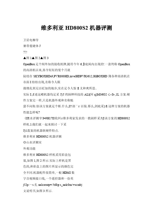
维多利亚HD800S2机器评测卫星电柳导赛带蔓婕体J竺!▲图1▲图2▲图3OpenBox足个闻外知的接收机牌,随符今年6,】底闲内出现的'.一款垮称OpenBox 的高清机以来,基令短短的曼个月就陆续存SKYBOXHDs9,PVR800HD,invelHDPVR3612,HiBOXHD簿各种商清机在市面I纷纷出现,名称令人眼拢缭乱到无以砭加的地步,实在足令人惊lI义和爽所思..实际I:,f:述这嵝机器均足采J}J湾扬钾科技的ALl(阿q|)M36O2心-It-,1L方案.硬件方案完一样,只是机器外观和名称魁蛩不问衙.似该方案就足个框.什么,|I!!部¨r以装.那么,剑底采}fl这种方案的机器性能怎样呢?《IJI水评测窄I=9H17II收纠r维多利家发求的一教阔样采J{I该方案的HD800S2样机.1:我们就一起来探讨一下采J}l泼案的机器软硬件特点.维多利亚HD800S2机器评测◎山水评测室外观功能维多利亚HD800S2样机采用彩盒包装,如图1,图2所示.实际上样机是黑色的,和彩盒上的图片所显示的颜色完全不同.机器配件很简单,一根HDMI数字音视频接口线,一个遥控器和一份英j52p:~s扎nalcorntp=//bl0g-s_nalc0m/wscmbj文说明书,如图3所示.图4为HD800S2机器前面板,分为左,中右三个功能区域,左边区域是操作按钮,上下左右方向键(频道+/一, 2010tf~i22Jt1]产品评测▲图4▲图5▲图6▲图7音量+/一),0K(确认),MENU(菜单)和STANDBY(待机)键共7个按键.中间区域是一个显示窗口,内置四位绿色LED数码管,指示频道序号和简单的英文字母信息,靠数码管的右边设有绿色的信号锁定,红色的待机指示灯.右边区域为一个仓盖,打开是一个CA插槽和一个CI模块接口.图5为HD800S2机器背面板,具有一组LNBlN和LNBOUT环路输出;音视频接口有一组A V接口,一组YPbPr接口,两个SCART接口这几种模拟接口, 一个HDMI,一个S/PDIFH轴这两种数字接口;另外还有一个RJ一45网口,一个RS一232串口以及一个USB接口,背面板上还有一个交流开关电源.HD800S2机器的体积大d,和长城318A机器的几乎一样,图6,图7为两者之间的对比.电路主板图8为HD800S2机器的内部结构,全机是由开关电源板,电路主板,CA卡座板和操作控制板四大块组成.其中电路主板正面,背面如图9,图1O所示.厂家告知,发来的评测机是采用手工焊接的样机, 和正式生产的机器在焊接工艺上存在一些差别.1.主控芯片HD800S2机器主控芯片被散热器覆盖,厂家告知型号为ALiM3602(U3).这是台湾扬智科技于2009年第一季度推出的一款MPEG一21H.264双解码高清芯片(图11),同期还推出了MPEG一2/ H.264双解码标清芯片M3381/M3381C.提到扬智(AL1)公司,可能烧友不太了解,但说起DVB—S采用的阿里方案,老烧友应该有所了解,早期的亚视达,天诚,迪艾特等接收机大都采用此设计方案,其实阿里就是ALl的译音,这家台湾公司早在DVD领域就有建树,如推出的0.18um制程的单芯片(整合侍服控制芯片与解码芯片)M3355,其方案与ESS,WlNBOND(华邦)等一起占有很大的市场.在DVB—S领域中,扬智公司从M3326M3327,M3328,M3329,M3330发展到现今的M3381,M3602,M3606,M3701,产品一直不断地推陈出新,已形成一个完整的Roadmap系列.其中M3602是高集成度,低成本的▲图8▲图9▲图10欢迎投稿一一一53l卫星电柳导j贲带萋嬗I峦I_三l兰兰竺▲图13▲图14▲图15MPEG一2/H.264双解码高清芯片,主要应用于高性价比的普及型高清机器后端解决方案中.《山水评测室》从网上了解到:最先采用M3602方案的是珠海中大的WS一3688F高清机.扬智官方给出了M3602芯片4-DVB—S2/ S解调器M3501的应用方案,如图12所示.在官方资料中显示:M3602内置嵌入式高性能396MHzMfPSCPU,内建MPEG一2MP@HL,H.264HP@L4.1高清格式解码器,JPEG图片格式解码加速器,支持DDRSDRAM内存,支持串行/并行FLASH,并行A TA接口(PATA)的硬盘设备,具有CA,CI输入接口,内建DVl和HDMI数字视频输出攫口,S/PDIF数字音频接口.2.存储器HD800S2机器采用SPIEPROM(U39)+2XDDRSDRAM(U4,U5)存储系统方案,如图13所示.其中U39是台湾Macronix(旺宏)公司的串行外设接口(SPI)CM0SEPR0M可擦写存储芯片MX2SL3205,容量4MB,用于系统程序的存储;U4,U5是日本ELPIDA (尔必达)公司的D5116AGTA一5B—E,这是一款DDR400内存芯片, 采用32MX16bit结构,存储容量为64MB,速度200MHz,两片总容量为128MB,用于系统运行中的数据存储内存.实际上,在U39焊盘上还标有另外一个U11标记,并设计了PCB走线,我们估计可以更换另外一款FLASH芯片达到系统升级扩容的问题.l54忡:~sanal∞Mp=..g.saJ.0cm啊3.HDMI接口保护芯片HD800S2机器的音视频输出可提供数字和模拟两种信号,数字视频接口采用了目前流行的HDMI接口,数字音频接口为S/PDIF同轴接口.令人可喜的是在HDMI接口上采用ESD保护芯片.业内人知道HDMl等高速数字接口的ESD保护是一项非常艰巨的任务,因为在高速数据速率下,保护电路带来电容性负载会大幅度降低信号的完整性.在ESD保护元件的选型原则上,主要有如下几点:(1)击穿电压应尽可能接近lC的工作电压,这样一旦电压稍高于正常工作电压,ESD保护器件便能快速导通.(2)箝位电压应尽可能低,防止受保护IC上的电压超出正常工作电压太多,箝位电压还应低于导致器件失效的破坏电压.(3)ESD保护器件最好有超低电容负载,以尽量减少由于电容负载引起的阻抗失配.除了早期采用分立的ESD保护元件外,现今的HDMf接口绝大多数选用单芯片ESD保护方案,这些ESD单芯片集成了多个分立元件,提供更多功能和线路匹配,如《山水评测室》之前评测机器所指出的长城318A—S2 就安装了这种ESD保护芯片CM202O~00TR.HD800S2机器HDMf接口(JH1)采用PN521(UH1)保护芯片,这是美国德州仪器(TI,Texas Instruments)公司的HDMIESD保护芯片TPD12S521的工厂标记,如图14 所示.TPD12S521芯片采用TSSOP一38 i]一~~一~\ll】_一i}]一一2ojo年第22期产品评测封装,其0.5mm的脚间距与HDMI插座的引脚间距是一样的,能提供无缝布局走线(图15),以消除差分信号对的走线毛刺.低速控制线提供电平转换功能,以消除对外部电平转换器fC的需要.在TPD12S521芯片第38个引脚上提供了一个额定输出电流为55mA的片上稳压器(图16),当输出为5v~l-I 55mAF]~,最大过流保护输出电压降是100mV.这一电流可使得HDMI接收器即便处于关机状态,也能够检测到发射信号.4.模拟音视频输出接口前面已经介绍过,HD800S2机器提供了一组A V接口(JY7),一组YPbPr接口(JY7)和两组SCART模拟音视频接口(SCART1),内部驱动电路如图17所示.其中CVBS复合视频信号采用FMS6143(U52)驱动芯片,在对F302+,DM800O机器的评测中,《山水评测室》多次介绍过该芯片, 这是一款8MHz带宽三通道视频滤波驱动芯片(LCVF),适合于480i/576i规格的标清视频接口驱动.而在HD800S2机器中,YPbPr接口驱动芯片为安森美半导体(Onsemi)公司的N2563(U42),这~0F302+,DM8000机器中使用的FMS6363芯片性能参数完全一样,都是30MHz带宽三通道LCVF,用于适合720p/1080i高清视频格式的芯片.由于M3602主控芯片未内置音频DAC,因此电路主板上采用了CS4334 (U53)音频DAC芯片,将数字音频信号转换为L/R模拟音频信号,再经过4558(U41)双运放构成音频前置电路放大后,为A V,SCART接口提供模拟音频信号.主板上4O53(u51)是一款常用的三组二路CMOS模拟开关芯片,内部含有三组单刀双掷开关.在HD800S2机器中,用于SCART接口的"iV/VCR连接信号的切换.5.网络接口芯片HDS00S2机器提供了一个RJ一45 网络接口(JL1),内部电路如图18所示.通过台湾CYL(卓智)PH16系列的网络变压器芯片PH163539TG作为电气隔离,将滤波后的高频信号传送到网络芯片LAN9220一ABZJ中. LAN9220是美国SMSC公司的一款支持可变电压I/O~[3HPAuto—MDIX 16位NOnPCI小型1o/100M以太网控制芯片,采用QFP一56P封装,在HD800S2机器中,主要用于网络数据的请求和下载.6.RS一232串行接口HD800S2机器RS一232串口(JR1)没有采用专用的RS一232接口转换芯片,而是采用两个贴片三极管构成的简单的分立元件电路来完成这种电平转换.7.调谐器部分HD800S2机器只有DVB—S/S2接收功能,采用CanTuner(铁壳调谐器)+板载解调器方案,如图19,图2O所示.其中CanTuner型号为夏普的$7VZ7306(TU2),内部采用IX247O锁相环芯片.板载解调器采用阿里自家的M3501芯片,这是一款DVB—S/S2解调芯片,内建双8位ADC,支持差分和单端模式,支持DVB—S/QPSK,DVB—S2的QPSK/8PSK/H8PSK/16APSK解调,支持DiSEqC20协,义,并具有低功耗待▲图16▲图17▲图18▲图19欢迎投稿:scm@sach'na.∞m55l卫星电鲫j贲带多嫂位l▲图2O▲图23▲图24▲图22一一●-';L=::黝LJ~LJ?..0',...…:二…一:▲图25▲图27机模式.对于调谐器输出的13/18V电压的切换和关断,HD800S2机器沿用了常见的三端可调式稳压芯片317T(UB1)构成的电路.B,CI接口由于主控芯片内置了接口模块,因此USB接口(JU1),Cl接口(Ji1)没有外置9区动芯片,是直接和主控芯片连接的,来实现外接U盘,移动硬盘以及CI模块的插入使用.其他电路板1.CA卡座板同样由于主控芯片内置了CA接口模块,因此CA卡座板(图21)仅仅是一个IS07816通用标准的卡座接口,通过排线和主板的JA1插J壅连接.2.操作控制板J56Mp=_sanal∞眦..怕HD800S2机器的操作控制板和一般的机器有所不同,如图22一图24所示,除了具有串行接口LED数码管及键盘管理芯片ET6202(IC080)外,还设置了一个SM894051C25(IC01)单片机.SM894051C25是台湾新茂(SyncMOS)的一款8位单片机,采用SOIC一20L封装.其功能和我们曾经在对430XP机器,MUTANT一200S机器(图25)介绍中使用的SM8952AC25基本一样,作为一种通用低成本的可编程控制器.在HD800S2机器中用于机器的运行操作以及开待机控制.SM894051C25工作频率可达25MHz,不过HD800S2操作控制板上所配的晶振(CXO1)为12.000MHz.因此MCU工作时钟频率为12MHz.3.开关电源板HD800S2机器的开关电源板采用SM8013C(U1)的电源管理芯片,这是一个新型的高性能的电流型PWM控制芯片.在HD800S2机器中,通过驱动外部高压MOSFET场效应晶体管CS2N60F (Q1)构成高效的开关电源,如图26,图27所示.2oio年第22期产品评测▲图28▲图29▲图3O▲图31▲图32▲图33▲图34▲图35▲图36▲图37▲图38▲图39▲图40▲图41▲图42▲图43▲图44▲图45欢投稿:w..m@..'?..57l匝虱贲带多嫂位II二竺竺.u▲图46▲图47▲图48一!!I▲图50▲图51SM8013C具有tP</J\的启动电流和工作电流,保证较低的待机功耗和很高的工作效率.在空载或者轻载的情况下,芯片会降低PwM工作频率,从而进一步氏开关损耗.在HD800S2机器开关电源板中,由D8组成的一路+24V电源经过主板电路的二次稳压后,向LNB提供13/18V极化切换电压;由D7组成的一路+12V电源向音频D/A芯片等供电;由D9,D10分别组成的两路+5V电源向调谐器,读卡器等供电,并经过主板的电源管理芯片产生3.3V,2.5V,1.3V电压,为主芯片,存储器,网络芯片等供电.使用和建议HD800S2机器的使用操作还是比较简单的,开机启动画面如图28所示.主界面有【编辑频道】,【安装】,【系统设置】,【工具】,【录制】和【本地网络设置】六大项目,从主菜单下的【工具】一【信息】可以查看到软件版本(图29),我们这台HD800S2样机采用图30的繁体中文版本.1,节目设置使用前,首先需要在【安装】项目里进行【天线设置】(图31),根据自身的配置方案,进行天线配置.例如,我们的115.5.E位于八切一的第四个端口下.那就在【DiSEqC1.1】项目上选择.2Cascades:Port4,依此类推,其他项目参数的设置如图32所示.设置完成后就可以选择"盲扫"模式进行搜索,HD800S2机器可以自动搜索出采用DVB—S,DVB—S2调制的信号,并在搜索界面中显示搜索到的电视和广播节目数量和实时滚动的节目名称,如果是节目中文名称,也能够正常显示,如图33,图34所示.f58Mp=~sana.∞p:..g.sa.一嗍2.节目播放搜索完成后,就可以收看节目了.按遥控器上的SATLIST键,可调出卫星列表,选择所需要收看的卫星,再按OK键选择节目,就可以播放了(图35,图36),在节目播放中,依次按遥控器上的INFO信息键,可显示当前节目信息条(图37),当前节目EPG(图38)和该节目的接收参数界面(图39).其中的节目信息条提供了丰富的节目信息显示功能,可指示节目的CA代码,有无EPG,字幕,图文信息,并且显示节目源分辨率,视频,音频编码格式.在节目播放中,按EPG键,可查看节目信息指南,由于系统软件内置了中文字库,因此能够支持中文解析(图40),但该功能只对携有EPG信息的节目有效.在节目播放中,按TXET,sUBTITLE键,可查看该频道的图文信息,显示字幕,但该功能只对携有图文信息,显示字幕的频道有效,否则会显示"没有数据.在节目播放中,按下FIND键,输入字母和数字可快速显示看名称开头含有该字符的频道(图41),以便用户快速切换.3.系统设置【系统设置】界面如图42所示,具有【语言】,【电视制式】,【显示设置】,【本地时间设置】,【定时器设置】,【父母锁】和【OSD设置】七大选项,其中的【语言】选项灰化,无法设置.【电视制式】选项主要是针对节目的显示格式进行设置,如图43所示.其中【视频分辨率】具有.480i,480p, 576i,576p,720p一50,720p一60, 1080i一50,1080i一60八种强制格式,该选项还可以通过遥控器上的2olo年第22期产品评测V.FORMA T快捷键直接选择.如果机器是通过HDMI接口连接电视机,则机器启动时会自动将视频分辨率调整到当前使用的HDMI电视可支持的最大模式.《山水评测室》提示:视频分辨率可选范围主要取决于用户所使用电视机能够支持的格式,其中720p_50,720p_60,1080i_50,1080i_60为高清画质格式,适合HDSOOS2机器和电视机对应的数字HDMI接口或模拟YPbPr接口连接,以16:9模式输出;480i,576i为标清隔行画质格式,适合于HD800S2机器的CVBS复合视频接口,SCART接口和电视机的普通A V接口连接,以4:3模式输出.而480p,576p为标清逐行画质格式,适合于HD8OOS2机器的YPbPr接口,SCART接口和电视机的YPbPr接l口连接,以4:3模式输出.不过,《山水评测室》使用发现,该机器没有50Hz,60Hz帧频的电视制式自适应模式,都是强制转换的.如设置为1080i一50格式,则对1080i一60格式的节目强制转换为1080i一50格式,这样多多少少会对画质有一些伤害,建议新版本中添加"自适应模式".【外观模式】选项主要是针对当前节目显示格式进行画面大小变换设置,具有"Auto,4:3PS(平移和扫描),4:3LB(信箱),16:9四个选项,建议选择"Auto".【显示设置】界面如图44所示,【本地时间设置】界面如图45所示,不过本地时间设置是采用节目转发器的时间,随着转发器的不同,本地显示时间也会改变,建议新版本中添加"网络效时"功能.4.网络设置HD800S2机器具有网络功能,这也是当今高清机最基本的一项要求.HD800S2机器支持现今流行的CCcam协议,只要~:CCcam.cfg文件复ffJU~Uu盘根目录下,再将U盘插入机器的USB接口, 然后通过以下步骤进行导入:(1)进入主菜单的【本地网络设置】界面(图46),选择【CCcam插件设置】项目,按OK进入.(2)选择【用USB升级文件】项目,在【添加升级文件】界面里(图47),选择"1CCcam.cfg(CCcam Plug)",再按遥控器的黄色键,读取升级文件.(3)机器自动读取和保存账号,并提示读取成功,如图48所示.(4)再进入【管理配置文件】选择"1CCcam.cfg(CCcamPlug)",在这里可以看刚才导入的账号,按遥控器的OK键勾选激活.(5)返回到【本地网络设置】中开启自动获取IP地址(图49),保存后,连接有效的网络并按遥控器上的POWER 键重新启动机器.(6)机器开始重新启动,并进行账号加载(图50),待机器正常运行时,再进入【管理配置文件】"1CCcam.cfg (CCcamPlug)"的界面中,发现显示"Online"(图51),表示已经登陆成功,这样就可以看CA节目了.5.PVR功能HD800S2机器通过连接外置的USB存储器(包括移动硬盘,U盘等)可实现PVR功能,主要包括节目的录制,回放和时光平移功能.使用该功能前,首先~gUSB存储器连接到机器背面板的▲图52▲图53▲图54▲图55▲图56▲图57欢迎投稿:w..m@.ch.n.?com59I▲图58▲图6O▲图61▲图62▲图63▲图64▲图65▲图66▲图67PVR接口上,不一会儿,屏幕提示机器"USB设备已连接正常".与此同时,原来灰化的【录制】界面项目全部变得可操作化.初次使用外置USB存储器时,需要进入【录制】界面(图52),进行【磁盘格式化】,如图53所示.由于目前的机器只有一个USB接口.因此【磁盘分区】选项为默认值,无法选择.选择【硬盘格式化】,按0K键确认后,系统会提示"Areyousureto formattheUSBPortitionl宁"用户可根J60hnp:,,wv哪sat_ch'nac.m『hnp://bl0gna?com^Ⅳscmb_i 据自己的需要选择"FAT,NTFS硬盘格式,注意:磁盘格式化将删除该存储器里的全部数据格式化后存储器后,会创建一个PVRSS2保存录制文件的文件夹.这样,就可以进行正常的录制节目了.(1)节目录制在节目播放中,按RECORD录制键可进行及时录制,录像时屏幕下方会出现录像进程框,如图54所示.录像进程框中用户可以看到已录制节目的名称, 日期,时间及节已录制当前节目的时长.在录制过程中,按EXIT键可退出录制进程显示界面,但屏幕右上角仍然显示REC,表示正在录制中.在录制过程中,再按RECORD录制可以设置录制持续时间,按EXIT退出键可选择停止录制.HDSOOS2机器还提供了预约录制功能,这从【系统设置】一【定时器设置】来实现,如图55,图56 所示.l《山水评测室》提示:1①在录制过程中,用户可按PAUSE键暂停画面播放,但不能暂停录制,录制仍然在进行中,只有按STOP键可彻底停止录制.②说明书上介绍:录制内容的时长最短为2分钟,最长为24,时,少于2分钟的录制系统不会进行保存,当录制时间达到120分钟或uA空间不足时系统会自动停止录制操作并退出此录制页面.经过《山水评测室》实际测试,我们目前使用的版本取消这种具有录制时间限制的功能,用户可以不受时间限制,随心所欲地录制节目2olo年第22疑产品评测(2)节目回放录制节目的回放操作比较麻烦,需要按遥控器上的MENU键,进入【录制】的【录像管理器】界面,选择刚才录制节目(图57)进行播放(图58).要返回节目播放状态中,需按STOP停止键,再按三次EXIT退出键.建议新版本中添加节目回放和退出的快捷键功能.在【录像管理器】界面中,不但可以进行节目的删除,重命名操作,还可以按绿色键可以输入机器的默认密码, 锁定录制文件.这样下次播放时必须输入密码才能看到录制的节目,这个功能不错,值得表扬一下.(3)电脑播放HD800S2机器录制的文件是以类"2008—01—01.04.0451一HD一529 "名称格式的子文件夹保存在PVRSS2 文件夹里,如图59所示.每一个子文件夹下有一个或多个容量不超过948MB 的DVR格式文件和一个固定的32KB容量info文件,其中前者录制节目文件,不过目前电脑中的大多数播放软件,编码软件和分离器无法识别这种格式的文件,因此无法直接播放.同样,经《山水评测室》测试,将电脑上ts格式的视频复制到PVR文件夹下,HD800S2机器均无法播放.即使改变文件名称和文件后缀名来符合HD800S2机器录制文件的命名要求,还是不能播放.可见,HD800S2机器是不能直接支持其它机器录制节目的视频播放的.(4)时光平移当在【录制】的【DVR配置】界面中开启时光平移功能时,机器将自动在PVR文件夹下生成test—write1和test—write2两个6MB文件,并将剩余磁盘空间的一半容量划给时光平移使用.此时遥控器上的PAUSE暂停键就变为时光平移启用键,再按PLAY播放键就可以进行时光平移中的播放,按住PAUSE暂停键可逐帧播放,按STOP停止键终止时光平移功能.(5)音乐和图片播放HD800S2机器可以播放硬盘中的JPG,BMP格式的图片文件,以及MP3格式的音乐文件,如图6O,图61所o6.节目编辑HD8OOS2机器上提供了简单的【编辑频道】功能(图62),如进行喜爱频道编辑,先进入图63的电视频道列表,按FA V键一OK键进行编辑.不过这种编辑非常麻烦,好在HD800S2机器上提供了频道编辑软件,并有RS一232串口,USB接口两种编辑方法.前者~0430xp机器的编辑方法类似.后者实际上是先将HD800S2机器的系统软件保存在U盘中,再导入到电脑中进行编辑,编辑完成后,再保存到U盘并通过接收机的USB升级功能刷写带有新频道的系统软件,这样就完成了编辑工作.具体方法如下:(1)将U盘插入机器中,通过【工具】一【用USB备份】,如图64所示.(2)按OK键进入,在【备份模式】上有"镜像文件"和"杂项文件"两个选项,这里选择"镜像文件",将光标移动到【开始】上,按OK键,在弹出的【备份镜像文件】界面上,如图65所示.共有四个可选项:①HDS2一DUMP.abs,对用户自定义机器设置进行备份;~systemSetting,▲图70▲图71:w..m@.'.'_.m6'I圜▲图74▲图75▲图76对用户设置的机器系统进行备份; CCcam.cfg,对系统中已储存的CCcam. cfg文件进行备份;constantCW,对constantCW文件进行备份.(3)可以选择①②两项,再按黄色键确认储存和备份(图66).备份完成后,按lNFO信息键可以查看备份结果(图67).(4)将U盘插入电脑中,打开频道编辑软件,选择OpenBinFile文件类型的HDS2一DUMP.abs文件,如图68所.(5)选择数据库类型为"USer DateBase(用户数据库)",展开AlJ Services(所有服务)项目,找到所需要编辑的节目名称双击它进行编辑,如图69所示.注意需要采用繁体字体编辑,否则编辑的节目名称在机器上无法正确显示.(6)对于一些相邻之间大量重复的频道,可以配合电脑键盘的"Shift"键进行快速删除,如图70所示.(7)展开FavoriteGroup(喜爱组)项目,在界面右边空白处,右击鼠标选择"EditGroup(编辑组)",如图71所示.在弹出【FavoriteGroup Edit(喜爱组编辑)]界面中添加各种类型的喜爱频道,并按OK键保存,如图72所示.(8)将编辑好的节目保存后,再将HDS2一DUMP.abs文件复制到U盘中,然后将U盘插到机器中,按照图73~图75进行升级,升级完成后,机器目动重届.(9)按遥控器上的FA V喜爱键,可以发现我们的中文台标已编辑成功,如图76所示.注意:喜爱频道文件夹名称目前无法显示,希望在新版本中得到改进.7.RS.232串口升级实际上在我们上面介绍的节目编辑中的(1)~(3)就是系统备份步骤,(8)就是系统升级步骤.当然这只是采用U盘的系统升级,如果采用u盘升级失败后,还可以采用机器提供的STBERomUpgrade软件通过RS一232串口升级来弥补.具体操作方法如下: (1)关闭机器的电源,用RS一232交叉串口线(注和DM5.0使p=~saacomgIsa…cm用的连接线一样)连接电脑串口和机器串口.(2)运行EromUpgrade.exe程序,其中[Port】端口,【BitsRate】速,【Parity】奇偶性,【Operate MOde】操作模式,按照默认选项进行,无需重新设置.在【FiIe】文件处选择刷机文件,并勾选【InCludeBootloader]包括引导程序的选项框,具体如图77所示.(3)按Next键,开始将电脑中的系统文件传送到机器的内存中,如图78 所示,当进度条到100%日寸,表示文件传送完成(图79).(4)继续按Next键,机器开始将保存在内存中的系统文件烧写~UFLASH 芯片中,如图80所示.请注意:这时千万不能断电或进行其他任何操作(5)当进度条再次到100%日寸,表示系统升级完成(图81),按Finished键结束串口刷机.8.更换背景画面HD800S2机器还提供了杂项文件备份和升级,也就是在上图65中选择"杂项文件",同样有四个可选项,其中的Tp_PROG.dbs(Sat,TP,Prog),对卫星列表,TP以及系统已储存的节目列表进行备份;②Back—logo.mSV (Backgroud),对系统背景进行备份;,选项和"镜像文件"里的相同.第项为我们提供了更改背景画面的方法,只要制作一个容量为42KB的M2V格式的视频文件,将它上传机器中,就可以替换原来的背景画面,图82为《山水评测室》制作的分辨率为1280×720《美丽的钓鱼岛》背景画面.2olo年第22期产品评测总评最后我们将已评测的F302+,DM8000,DM800打造版三款高清机和HD800S2机器作一个简单的功能对比,如图83,图84所示.1.门限问题对于采用S7VZ7306卫星调谐器+M3501板载解调器构成的HD800S2机器的门限问题,《山水评测室》和采用国产易尔达EDS一4B47FF1B一体化调谐器的F302+机器,采用BCM4501的板载调谐器的DM8000机器以及采用日本ALPS(阿尔卑斯)BSBE2—401A一体化调谐器的DM800机器作出对比测试.在同等接收条件,在高频头波导管口处贴上一段铝箔,人为降低信号质量,接收部分转发器节目,以画面观感为主,测试数据如表1.通过简单的测试我们发现:在这四款高清机中,无论是DVB—S2信号的接收,还是DVB—S信号,这台HD800S2样机都有不错的表现,接收门限仅次于DM8000机器,这是我们料想不到的.2.开机,待机,换台时间在未连接硬盘,不激活机器网络功能的同等条件下,经测试,HD800S2机器在。
开源地图OpenStreetMap在无人驾驶系统中的应用

47软件开发与应用Software Development And Application电子技术与软件工程Electronic Technology & Software Engineering1 OpenStreetMap概述开放街道地图(OpenStreetMap ,简称OSM )是一个受到维基百科概念启发的自发地理信息项目。
该项目由英国软件工程师史蒂夫科斯特于2004年创建,其初衷是创造一个内容自由且所有用户都能编辑的世界地图。
经过多年的积累,OSM 目前已囊括了世界绝大部分地区的详细地理信息。
OSM 的地图数据来源包括手持式GPS 设备,航拍图,卫星影像,或传统的地区地图,注册用户们通过这些数据来保证OSM 的精确性及时效性。
在知名GIS 供应商GoogleEarth 自2012年开始引入收费API 机制以后,越来越多的大型网站和应用开始转向使用OSM 提供GIS 信息支撑,其中包括苹果的自有地图服务AppleMaps 和微软的Here 地图业务。
个人用户和大型企业的贡献使得OSM 的准确程度在快速提高。
一篇来自爱尔兰国立大学的论文[1]指出,在绝大多数情况下,OSM 能够提供和GoogleMap 或微软Here 地图等商业地图同等的信息量和几乎一致的准确地理数据,这说明OpenStreetMap 项目已足够在商业中使用。
2 封闭场景下的无人驾驶需要什么样的地图通过对无人驾驶系统所面对的速度,装载内容,以及道路情况的划分,无人驾驶所面对的场景可被分为封闭场景和开放道路场景。
一般而言,封闭场景包括港口,矿山,物流货场等不会有未经许可的社会车辆或人员进场的场景。
对于无人驾驶系统而言,封闭场景具有以下两个特点。
一是在正常情况下,所有车辆,人员,以及路旁设备均处于系统的统一监控下并可以通过相应传感器或地图确定位置,几乎不会出现未经注册的车辆或行人。
二是道路或场内设备位置的一切变动都处于计划内,不会出现无法预知的变动,如未经通知的临时维修或临时变道。
迈巴迪RLX导航系统指南说明书

Restriction Level While Driving
Voice command only Not restricted Voice command only. Limited to three screens Voice command only Not restricted Not restricted Voice command only. Limited to three screens Not restricted Voice command only. Limited to three screens Voice command only Voice command only Voice command only Limited use Restricted Restricted Restricted Restricted
Map Screen Legend
33 19
Calculated route
Time to go
Distance to go
Next guidance point
Current vehicle location
Turn-by-Turn Directions
Shows a more detailed view of the next maneuver during route guidance on the multi-information display. See your Owner’s Manual for instructions on how to turn this feature on or off.
Magellan RoadMate 6630T-LM 快速入门指南说明书

®Magellan® RoadMate® 6630T-LM GPS Navigator & HD Dash Cam ComboQuick Start GuideFCC Statement:This device complies with part 15 of the FCC Rules. Operation is subject to the following two conditions: (1) This device may not cause harmful interference, and (2) this device must accept any interference received, including interference that may cause undesired operation.This equipment has been tested and found to comply with the limits for a Class B digital device, pursuant to part 15 of the FCC Rules. These limits are designed to provide reasonable protection against harmful interference in a residential installation. This equipment generates, uses and can radiate radio frequency energy and, if not installed and used in accordance with the instructions, may cause harmful interference to radio communications. However, there is no guarantee that interference will not occur in a particular installation. If this equipment does cause harmful interference to radio or television reception, which can be determined by turning the equipment off and on, the user is encouraged to try to correct the interference by one or more of the following measures:—Reorient or relocate the receiving antenna.—Increase the separation between the equipment and receiver.—Connect the equipment into an outlet on a circuit different from that to which the receiver is connected.—Consult the dealer or an experienced radio/TV technician for help.Caution: Any changes or modifications not expressly approved by the party responsible for compliance could void the user's authority to operate the equipment.This equipment complies with FCC radiation exposure limits set forth for an uncontrolled environment.This transmitter must not be co-located or operating in conjunction with any other antenna or transmitter.IC Statement:This device complies with Industry Canada licence-exempt RSS standard(s). Operation is subject to the following two conditions:(1) this device may not cause interference, and(2) this device must accept any interference, including interference that maycause undesired operation of the device.Le présent appareil est conforme aux CNR d’Industrie Canada applicables aux appareils radio exempts de licence. L’exploitation est autorisée aux deux conditions suivantes :(1) l’appareil ne doit pas produire de brouillage, et(2) l’utilisateur de l’appareil doit accepter tout brouillage radioélectrique subi, même si le brouillage est susceptible d’en compromettre le fonctionnement.IC Radiation Exposure Statement:This equipment complies with Canada radiation exposure limits set forth for uncontrolled environments.This transmitter must not be co-located or operating in conjunction with anyother antenna or transmitter.Déclaration d’IC sur l’exposition aux radiations:Cet équipement est conforme aux limites d’exposition aux radiations définies par le Canada pour des environnements non contrôlés.Cet émetteur ne doit pas être installé au même endroit ni utilisé avec une autre antenne ou un autre émetteur.5 6 7 89 10 11 12Camera Lens Micro SD Slot (DVR Recording) Power Button Micro SD Slot(diagnostics only)Video InUSB Connector,Power InputSearch ButtonCreate Route ButtonDVR Recording ButtonAddress Book ButtonSettings Menu Button4 5 67 8 9Pause Routing Driving Status DVR Recording Multi-DestinationRoute ButtonSettings Menu ButtonOrientation ButtonTraffic Status IconNext Maneuver IconNext ManeuverInstructionson the Welcome screen.2. Tap your language preference > tap .3. Read the End User License Agreement.5a. If you already have a Magellan account, taptap5b. To register later, tap > tapYou cannot download map or software updates until you log in or register.6. Enter your account details > tap .to calibrate LDWS and FCWS.to complete initial setup and start free driving.from the Map screen.Updates when you see a notification (e.g. 2 New Updates).4. Wait for the new map or software to download.Updated maps or software are now downloaded.from the Map screen.2. Tap .Calibration to calibrate the camera for FCWS and LDWS.1. Tap from the Map screen.2. Tap .3. Tap Lane Departure Warning System (LDWS) (FCWS).4. Tap Beep to hear an alert sound,FCWS Alert Icon LDWS Alert Icon (Right Side)LDWS Alert Icon (Left Side)from the Map screen.to begin recording video.to return to the Map screen. The DVR Recording button changes to the Map screen while recording is in progress.To stop recording, tap from the Map screen > tapfrom the Map screen..Video Time > selectThis time limit also applies toTap and holdAccess Recorded Videos and Photos.from the Map screen.2. Tap any of the time-stamped files to view them, or tap of all file playback types (below).3. Tap on a folder to view time-stamped files.from the Map screen.3. Tap the check box next to Headlight Reminder to turn the Headlight Reminder on (checked) or off (unchecked).。
- 1、下载文档前请自行甄别文档内容的完整性,平台不提供额外的编辑、内容补充、找答案等附加服务。
- 2、"仅部分预览"的文档,不可在线预览部分如存在完整性等问题,可反馈申请退款(可完整预览的文档不适用该条件!)。
- 3、如文档侵犯您的权益,请联系客服反馈,我们会尽快为您处理(人工客服工作时间:9:00-18:30)。
TM
Freescale i.MX Application Processors
i.MX 6Quad i.MX53
2012
Content Creation, Technology Driver
Netbook
i.MX 6Dual
i.MX51 i.MX50
2012
Jun 2011
Color eReader
• •
Embedded Multimedia
• •
Pioneer in portable media players Eleven tablet products based on i.MX shipping in 2010 and design win momentum continuing to build
2
Freescale™ and the Freescale logo are trademarks of Freescale Semiconductor, Inc. All other product or service names are the property of their respective owners. © Freescale Semiconductor, Inc. 2010.
•
Introducing the i.MX 6 Series
Software and hardware compatibility between families makes it even easier to build a portfolio of products quickly
Best-in-class performance enabled by quad core processing, low power consumption and bleeding-edge multimedia and graphics Fast development through simplified hardware design, flexible interfaces and easy-to-use development kits Optimized peripheral sets tailored to serve automotive, industrial and consumer markets Available in 2012
•
•
►
A list of participating Freescale products is available at: /productlongevity
Freescale™ and the Freescale logo are trademarks of Freescale Semiconductor, Inc. All other product or service names are the property of their respective owners. © Freescale Semiconductor, Inc. 2010.
Breaking the Boundaries of User Experience
Freescale™ and the Freescale logo are trademarks of Freescale Semiconductor, Inc. All other product or service names are the property of their respective owners. © Freescale Semiconductor, Inc. 2010.
Broad traction in the embedded market Connected display based devices in consumer, medical and industrial markets
Freescale™ and the Freescale logo are trademarks of Freescale Semiconductor, Inc. All other product or service names are the property of their respective owners. © Freescale Semiconductor, Inc. 2010.
#1 market share in eReader market • Selected by 4 out of the top 5 eReader vendors for next-generation designs • >2X unit shipments in 2010
Smart Mobile Devices
•
►
For the automotive and medical segments, Freescale will make a broad range of program devices available for a minimum of 15 years For all other market segments in which Freescale participates, Freescale will make a broad range of devices available for a minimum of 10 years Life cycles begin at the time of launch
Good, Better, Best Differentiation
TM
NEW
Media Tablet
Luxury Infotainment
Advanced HMI
Performance/ Multimedia Capability
i.MX Application Processor General Embedded NDA Roadmap
Execution Samples w/BSP Production
Video: QVGA – D1 dec LCD: Segmented to WVGA PMIC: Integrated
STMP37xx
2011
2012
2013
TM
Freescale™ and the Freescale logo are trademarks of Freescale Semiconductor, Inc. All other product or service names are the property of their respective owners. © Freescale Semiconductor, Inc. 2010.
Smart Energy Meter
Freescale™ and the Freescale logo are trademarks of Freescale Semiconductor, Inc. All other product or service names are the property of their respective owners. © Freescale Semiconductor, Inc. 2010.
Premium
CPU: 1GHz+ multi-core
2500 – 14,000+ DMIPS Graphics: Adv 2D+3D HW i.MX 6Quad
Video: >1080p enc/dec LCD: >1080p PMIC: Integrated/Separate CPU: 1-2 core NhomakorabeaTM
Freescale Multimedia Traction
Automotive
• •
eReaders
•
Leadership in Telematics and advanced automotive infotainment Selected by 7 out of the top 10 automotive OEMs for next-generation designs
Industry’s Most Scalable Family of Multimedia Applications Processors
Build scalable product lines with the new i.MX 6 series — ultimate versatility with compatible single, dual and quad core devices
i.MX 6Dual
ARM9 ARM11 Cortex-A8 Cortex-A9
i.MX 6Solo
Production Proposal
CPU: Single core
400 – 800MHz 500 – 1000 DMIPS Graphics: Basic 2D HW
Entry
i.MX28 i.MX27 i.MX25 i.MX233 i.MX 6Solo Lite
i.MX
Your Interface to the World
i.MX families offer the most versatile platforms for multimedia and display applications, bringing personality and interactivity to a whole new world of products
TM
3
Freescale Product Longevity Program
► ►
The embedded market needs long-term product support Freescale has a longstanding track record of providing long-term production support for our products Freescale is pleased to introduce a formal product longevity program for the market segments we serve