Abstract A feedback-based model for IO servicing
前馈型电压模式控制逆变器研究
何启晨 卢伟国 周雒维
(重庆大学输配电装备及系统安全与新技术国家重点实验室 重庆市 400030) 摘要 在传统电压模式基础上,对单相全桥逆变器提出了一种前馈型电压模式控制方案,利 用开关变换器稳态输入输出占空比关系构造控制方程,引入输入电压前馈使得输入电压波动对 输出无影响,同时在无积分反馈环节下输出电压就能稳定跟踪参考信号,避免了 PID 控制中积 分项对系统性能的影响,控制实现上则采用输入电压积分电路求解控制方程中的开关占空比。 进行了性能分析并与传统 PID 控制逆变器的模型比较,理论分析表明前馈型电压模式控制逆变 器具有稳态跟踪性能好,抗输入电压扰动以及对负载跳变动态响应好的优点。进行了仿真对比 和实验验证,结果表明理论分析的正确性和前馈型电压模式控制的有效性。此外,所提控制方 案具有控制简单,模拟电路容易实现的优点,便于实际应用。 关键词:逆变器 前馈 电压模式 比例反馈 动态性能 中图分类号: TM464
t0 Ts
t0 dTs
(vi vo )dt 0
(1)
由于开关频率足够高, 则在一个开关周期内输入电 压 vi 和输出交流电压 vo 近似不变,为简单起见仍 用其符号表示其一个开关周期的平均值,则式 (1) 可变为
(vi vo ) dTs (vi vo ) (1 d )Ts 0
性能。 此外, 在输入端由于实际逆变器中直流输入 电压并不是恒定不变的, 在仅有反馈的情况下输出 电压受输入电压波动的影响。 为此, 在传统电压模 式结构基础上, 考虑在无积分环节时仍能保证输出 电压的稳态精度, 同时引入输入电压前馈来消除其 波动对输出电压的影响。
L
S1 vi S2
S3
+
iL
分析报告英语作文

分析报告英语作文AbstractWith the advancement of globalization, English has become an essential tool for communication in various fields. The analysis report of English essays aims to explore the characteristics, structure, and techniques that can help students improve their writing skills and excel in the English language.IntroductionEnglish essays play a crucial role in language learning and academic success. This report analyzes the key elements of a well-structured English essay, including its introduction, body, and conclusion. By understanding these components, students can enhance their writing abilities and effectively convey their ideas in English.Characteristics of a Good English EssayA good English essay should exhibit clarity, coherence, and conciseness. It should present a clear thesis statement in the introduction, followed by well-organized supporting arguments in the body paragraphs. Additionally, the conclusion should effectively summarize the main points discussed in the essay.Structure of an English EssayIntroductionThe introduction serves as the opening paragraph of an essay and should capture the reader’s attention. It usually includes a hook, background information, and a thesis statement that outlines the main argument of the essay.Body ParagraphsThe body paragraphs make up the main portion of the essay and provide detailed explanations and evidence to support the thesis statement. Each paragraph should focus on a single idea and include relevant examples and analysis.ConclusionThe conclusion brings the essay to a close by summarizing the main points and restating the thesis statement in different words. It should leave a lasting impression on the reader and provide a sense of closure to the essay.Techniques for Improving English Writing Skills1.Practice Writing Regularly: Regular practice is essential forimproving English writing skills. Students should dedicate time each day towrite essays, journal entries, or short stories to enhance their writing abilities.2.Seek Feedback: Feedback from teachers, peers, or writing tutors canhelp students identify areas for improvement in their writing. Constructivecriticism and suggestions can aid in refining their writing skills.3.Expand Vocabulary: A diverse vocabulary can enrich students’writing and make their essays more engaging. Learning new words and using them appropriately in essays can enhance the overall quality of their writing.4.Review Grammar and Punctuation: Proper grammar andpunctuation are vital for effective communication in English writing. Students should review grammar rules and practice using correct punctuation to ensure clarity in their essays.ConclusionIn conclusion, the analysis report of English essays highlights the essential components of a well-written essay, including its structure, characteristics, and techniques for improvement. By mastering these elements, students can enhance their writing skills and express their ideas effectively in English. Continuous practice, feedback, and vocabulary expansion are crucial for achieving success in English writing.。
基于新型全阶观测器的感应电机无速度传感器控制
Voe. 54. No. 5Mg. 2021第54卷第5期2021年 5月微电机MICROMOTORS基于新型全阶观测器的感应电机无速度传感器控制胡锦涛,邵宜祥,庄圣伦,孙素娟,周百灵,孙立鑫(南瑞集团(国网电力科学研究院)有限公司,南京211106)摘 要:随着我国海上风电的迅猛发展,感应电机作为一种主流电机已广泛用作海上风电中的发电机组%针对感应电机无速度传感器控制中转速估 大、过渡不平滑及 矩阵的 大等问题, 了 化型反馈矩阵的新型全阶观测器方案。
时极点平移法推导出 矩阵中各元素的表达式,再从与 度两方 ,提出 矩阵的简化思想,以减小 及 度。
通过对方案真与 ,结果表明型全阶观测器在感应电机的无速度传感器控制过程中观测精度高,动态性能好,工程 强。
关键词:感 电机;无速度传感器;矩阵;全阶观测器;极平移法中图分类号:TM346; TP273 文献标志码:A文章编号:1001-848(2021 )05预079预7Speed Sensorless Control of Induction Motor Based on New Full-order ObserverHUJonoao , SHAOYotoang , ZHUANGShengeun , SUNSueuan , ZHOUBaoeong , SUNLoton(NARI Group Corgoration ( Stato Grid Electric Powes Researct Institoto ),Nanking 211106,Chin a )Abstract : WiW the rapid development of oashon wind power in our counWy , the induction motors have beenwiOely used as generator sets in dfshoro wind power as a mainstream motor. A new full-5rder obse/er scheme based on a simpliOed feedback matao was designed. It was mainly used to solve these problems , in cluding larae speed estimation vror , low transition smoothness, and larae feedback matao ctlculgon inspeed sensorless control of induction motors. The exp/ssion of each element in We feedback matao was de-aved by means of the pole shift method in We beginning and Wen a simplified iOea of feedback matao was proposed to reduco We amount of calculation and the difficulty of implementation consiOeang We two aspectsof stability and converaenco speed duang the process of design. After simulation and expeament of the scheme ,tCe results show that the new full-5rder obse/er has high obse/ation accu/cy ,good dynamic per-fo/nanco and strong engineeang practicability in tCe speed sensorless control process of induction motor.Key words : induction motor ; speed sensorless ; feedback matax ; full-5rder obse/er; pole shift methodo 引言近年来,我国海上风电装机容量越来越大(1-),随着产业链的成本 及单机 的扩大,使得感电机风电机以 靠性、 单、低成本等逐步成为我国海 电的主流机型。
Eliminating stack overflow by abstract interpretation
In Proceedings of the3rd International Conference on Embedded Software,Philadelphia,PA,pages306–322,October13–15,2003.c Springer-Verlag. Eliminating stack overflow by abstract interpretationJohn Regehr Alastair Reid Kirk WebbSchool of Computing,University of UtahAbstract.An important correctness criterion for software running on embeddedmicrocontrollers is stack safety:a guarantee that the call stack does not over-flow.We address two aspects of the problem of creating stack-safe embeddedsoftware that also makes efficient use of memory:statically bounding worst-casestack depth,and automatically reducing stack memory requirements.Ourfirstcontribution is a method for statically guaranteeing stack safety by performingwhole-program analysis,using an approach based on context-sensitive abstractinterpretation of machine code.Abstract interpretation permits our analysis toaccurately model when interrupts are enabled and disabled,which is essentialfor accurately bounding the stack depth of typical embedded systems.We haveimplemented a stack analysis tool that targets Atmel A VR microcontrollers,andtested it on embedded applications compiled from up to30,000lines of C.Weexperimentally validate the accuracy of the tool,which runs in a few secondson the largest programs that we tested.The second contribution of this paper isa novel framework for automatically reducing stack memory requirements.Weshow that goal-directed global function inlining can be used to reduce the stackmemory requirements of component-based embedded software,on average,to40%of the requirement of a system compiled without inlining,and to68%of therequirement of a system compiled with aggressive whole-program inlining that isnot directed towards reducing stack usage.1IntroductionInexpensive microcontrollers are used in a wide variety of embedded applications such as vehicle control,consumer electronics,medical automation,and sensor networks. Static analysis of the behavior of software running on these processors is important for two main reasons:–Embedded systems are often used in safety critical applications and can be hard to upgrade once deployed.Since undetected bugs can be very costly,it is useful to attempt tofind software defects early.–Severe constraints on cost,size,and power make it undesirable to overprovision resources as a hedge against unforeseen demand.Rather,worst-case resource re-quirements should be determined statically and accurately,even for resources like memory that are convenient to allocate in a dynamic style.0 KB4 KB Without stack boundingWith static stack bounding Fig.1.Typical RAM layout for an embedded program with and without stack bounding.Without a bound,developers must rely on guesswork to determine the amount of storage to allocate to the stack.In this paper we describe the results of an experiment in applying static analysis techniques to binary programs in order to bound and reduce their stack memory re-quirements.We check embedded programs for stack safety :the property that they will not run out of stack memory at run time.Stack safety,which is not guaranteed by tra-ditional type-safe languages like Java,is particularly important for embedded software because stack overflows can easily crash a system.The transparent dynamic stack ex-pansion that is performed by general-purpose operating systems is infeasible on small embedded systems due to lack of virtual memory hardware and limited availability of physical memory.For example,8-bit microcontrollers typically have between a few tens of bytes and a few tens of kilobytes of RAM.Bounds on stack depth can also be usefully incorporated into executable programs,for example to assign appropriate stack sizes to threads or to provide a heap allocator with as much storage as possible without compromising stack safety.The alternative to static stack depth analysis that is currently used in industry is to ensure that memory allocated to the stack exceeds the largest stack size ever observed during testing by some safety margin.A large safety margin would provide good in-surance against stack overflow,but for embedded processors used in products such as sensor network nodes and consumer electronics,the degree of overprovisioning must be kept small in order to minimize per-unit product cost.Figure 1illustrates the rela-tionship between the testing-and analysis-based approaches to allocating memory for the stack.Testing-based approaches to software validation are inherently unreliable,and test-ing embedded software for maximum stack depth is particularly unreliable because its behavior is timing dependent:the worst observed stack depth depends on what code is executing when an interrupt is triggered and on whether further interrupts trigger before the first returns.For example,consider a hypothetical embedded system where the maximum stack depth occurs when the following events occur at almost the same time:1)the main program summarizes data once a second spending 100microseconds2at maximum stack depth;2)a timer interruptfires100times a second spending100mi-croseconds at maximum stack depth;and3)a packet arrives on a network interface up to10times a second;the handler spends100microseconds at maximum stack depth.If these events occur independently of each other,then the worst case will occur roughly once every10years.This means that the worst case will probably not be discovered during testing,but will probably occur in the real world where there may be many in-stances of the embedded system.In practice,the events are not all independent and the timing of some events can be controlled by the test environment.However,we would expect a real system to spend less time at the worst-case stack depth and to involve more events.Another drawback of the testing-based approach to determining stack depth is that it treats the system as a black box,providing developers with little or no feedback about how to best optimize memory usage.Static stack analysis,on the other hand,identifies the critical path through the system and also the maximum stack consumption of each function;this usually exposes obvious candidates for optimization.Using our method for statically bounding stack depth as a starting point,we have developed a novel way to automatically reduce the stack memory requirement of an em-bedded system.The optimization proceeds by evaluating the effect of a large number of potential program transformations in a feedback loop,applying only transformations that reduce the worst-case depth of the stack.Static analysis makes this kind of opti-mization feasible by rapidly providing accurate information about a program.Testing-based approaches to learning about system behavior,on the other hand,are slower and typically only explore a fraction of the possible state space.Our work is preceded by a stack depth analysis by Brylow et al.[3]that also per-forms whole-program analysis of executable programs for embedded systems.How-ever,while they focused on relatively small programs written by hand in assembly lan-guage,we focus on programs that are up to30times larger,and that are compiled from C to a RISC architecture.The added difficulties in analyzing larger,compiled programs necessitated a more powerful approach based on context-sensitive abstract interpreta-tion of machine code;we motivate and describe this approach in Section2.Section3 discusses the problems in experimentally validating the abstract interpretation and stack depth analysis,and presents evidence that the analysis provides accurate results.In Sec-tion4we describe the use of a stack bounding tool to support automatically reducing the stack memory consumption of an embedded system.Finally,we compare our research to previous efforts in Section5and conclude in Section6.2Bounding Stack DepthEmbedded system designers typically try to statically allocate resources needed by the system.This makes systems more predictable and reliable by providing a priori bounds on resource consumption.However,an almost universal exception to this rule is that memory is dynamically allocated on the call stack.Stacks provide a useful model of storage,with constant-time allocation and deallocation and without fragmentation.Fur-thermore,the notion of a stack is designed into microcontrollers at a fundamental level. For example,hardware support for interrupts typically pushes the machine state onto3the stack before calling a user-defined interrupt handler,and pops the machine state upon termination of the handler.For developers of embedded systems,it is important not only to know that the stack depth is bounded,but also to have a tight bound—one that is not much greater than the true worst-case stack depth.This section describes the whole-program analysis that we use to obtain tight bounds on stack depth.Our prototype stack analysis tool targets programs for the Atmel A VR,a popular family of microcontrollers.We chose to analyze binary program images,rather than source code,for a number of reasons:–There is no need to predict compiler behavior.Many compiler decisions,such as those regarding function inlining and register allocation,have a strong effect on stack depth.–Inlined assembly language is common in embedded systems,and a safe analysis must account for its effects.–The source code for libraries and real-time operating systems are commonly not available for analysis.–Since the analysis is independent of the compiler,developers are free to change compilers or compiler versions.In addition,the analysis is not fragile with respect to non-standard language extensions that embedded compilers commonly use to provide developers withfine-grained control over processor-specific features.–Adding a post-compilation analysis step to the development process presents de-velopers with a clean usage model.2.1Analysis Overview and MotivationThefirst challenge in bounding stack depth is to measure the contributions to the stack of each interrupt handler and of the main program.Since indirect function calls and recursion are uncommon in embedded systems[4],a callgraph for each entry point into the program can be constructed using standard analysis techniques.Given a callgraph it is usually straightforward to compute its stack requirement.The second,more difficult,challenge in embedded systems is accurately estimating interactions between interrupt handlers and the main program to compute a maximum stack depth for the whole system.If interrupts are disabled while running interrupt handlers,one can safely estimate the stack bound of a system containing interrupt handlers using this formula:stack bound depth(main)depth(interrupt)However,interrupt handlers are often run with interrupts enabled to ensure that other interrupt handlers are able to meet real-time deadlines.If a system permits at most one concurrent instance of each interrupt handler,the worst-case stack depth of a system can be computed using this formula:stack bound depth(main)depth(interrupt)4Fig.2.This fragment of assembly language for Atmel A VR microcontrollers motivates our approach to program analysis and illustrates a common idiom in embedded soft-ware:disable interrupts,execute a critical section,and then reenable interrupts only if they had previously been enabledUnfortunately,as we show in Section3,this simple formula often provides unneces-sarily pessimistic answers when used to analyze real systems where only some parts of some interrupt handlers run with interrupts enabled.To obtain a safe,tight stack bound for realistic embedded systems,we developed a two-part analysis.Thefirst must generate an accurate estimate of the state of the proces-sor’s interrupt mask at each point in the program,and also the effect of each instruction on the stack depth.The second part of the analysis—unlike thefirst—accounts for potential preemptions between interrupts handlers and can accurately bound the global stack requirement for a system.Figure2presents a fragment of machine code that motivates our approach to pro-gram analysis.Analogous code can be found in almost any embedded system:its pur-pose is to disable interrupts,execute a critical section that must run atomically with respect to interrupt handlers,and then reenable interrupts only if they had previously been enabled.There are a number of challenges in analyzing such code.First,effects of arithmetic and logical operations must be modeled with enough ac-curacy to track data movement through general-purpose and special-purpose registers. In addition,partially unknown data must be modeled.For example,analysis of the code fragment must succeed even when only a single bit of the CPU status register—the master interrupt control bit—is initially known.Second,dead edges in the control-flow graph must be detected and avoided.For ex-ample,when the example code fragment is called in a context where interrupts are dis-abled,it is important that the analysis conclude that the sei instruction is not executed since this would pollute the estimate of the processor state at subsequent addresses.Finally,to prevent procedural aliasing from degrading the estimate of the machine state,a context sensitive analysis must be used.For example,in some systems the code501 (a)Lattice for each bit in the machine stateand1000101111xor110101(b)Logical operations on abstract bits and combining machine states at merge pointsFig.3.Modeling machine states and operations in the abstract interpretationin Figure2is called with interrupts disabled by some parts of the system and is called with interrupts enabled by other parts of the system.With a context-insensitive ap-proach,the analysis concludes that since the initial state of the interruptflag can vary,thefinal state of the interruptflag can also vary and so analysis of both callers of the function would proceed with the interruptflag unknown.This can lead to large over-estimates in stack bounds since unknown values are propagated to any code that could execute after the call.With a context-sensitive analysis the two calls are analyzed sepa-rately,resulting in an accurate estimate of the interrupt state.The next section describes the abstract interpretation we have developed to meet these challenges.2.2Abstracting the Processor StateThe purpose of our abstract interpretation is to generate a safe,precise estimate of the state of the processor at each point in the program;this is a requirement forfindinga tight bound on stack depth.Designing the abstract interpretation boils down to twomain design decisions.First,how much of the machine state should the analysis model?For programs thatwe have analyzed,it is sufficient to model the program counter,general-purpose regis-ters,and several I/O registers.Atmel A VR chips contain32general-purpose registers and64I/O registers;each register stores eight bits.From the I/O space we model theregisters that contain interrupt masks and the processor status register.We do not model main memory or most I/O registers,such as those that implement timers,analog-to-digital conversion,and serial communication.Second,what is the abstract model for each element of machine state?We chose to model the machine at the bit level to capture the effect of bitwise operations on theinterrupt mask and condition code register—we had initially attempted to model themachine at word granularity and this turned out to lose too much information through conservative approximation.Each bit of machine state is modeled using the lattice de-picted in Figure3(a).The lattice contains the values0and1as well as a bottom element, ,that corresponds to a bit that cannot be proven to have value0or1at a particular program point.Figure3(b)shows abstractions of some common logical operators.Abstractions of operators should always return a result that is as accurate as possible.For example,6when all bits of the input to an instruction have the value0or1,the execution of the instruction should have the same result that it would have on a real processor.In this respect our abstract interpreter implements most of the functionality of a standard CPU simulator.For example,when executing the and instruction with as one argument and as the other argument,the result register will con-tain the value.Arithmetic operators are treated similarly,but re-quire more care because bits in the result typically depend on multiple bits in the input. Furthermore,the abstract interpretation must take into account the effect of instructions on processor condition codes,since subsequent branching decisions are made using these values.The example in Figure2illustrates two special cases that must be accounted for in the abstract interpretation.First,the add-with-carry instruction adc,when both of its arguments are the same register,acts as rotate-left-through-carry.In other words,it shifts each bit in its input one position to the left,with the leftmost bit going into the CPU’s carryflag and the previous carryflag going into the rightmost bit.Second,the exclusive-or instruction eor,when both of its arguments are the same register,acts like a clear instruction—after its execution the register is known to contain all zero bits regardless of its previous contents.2.3Managing Abstract Processor StatesAn important decision in designing the analysis was when to create a copy of the ab-stract machine state at a particular program point,as opposed to merging two abstract states.The merge operator,shown in Figure3(b),is lossy since a conservative approx-imation must always be made.We have chosen to implement a context-sensitive anal-ysis,which means that we fork the machine state each time a function call is made, and at no other points in the program.This has several consequences.First,and most important,it means that the abstract interpretation is not forced to make a conservative approximation when a function is called from different points in the program where the processor is in different states.In particular,when a function is called both with inter-rupts enabled and disabled,the analysis is not forced to conclude that the status of the interrupt bit is unknown inside the function and upon return from it.Second,it means that we cannot show termination of a loop implemented within a function.This is not a problem at present since loops are irrelevant to the stack depth analysis as long as there is no net change in stack depth across the loop.However,it will become a problem if we decide to push our analysis forward to bound heap allocation or execution time.Third, it means that we can,in principle,detect termination of recursion.However,our current implementation rarely does so in practice because most recursion is bounded by values that are stored on the stack—which our analysis does not model.Finally,forking the state at function calls means that the state space of the stack analyzer might become large.This has not been a problem in practice;the largest programs that we have ana-lyzed cause the analyzer to allocate about140MB.If memory requirements become a problem for the analysis,a relatively simple solution would be to merge program states that are identical or that are similar enough that a conservative merging will result in minimal loss of precision.72.4Abstract Interpretation and Stack Analysis AlgorithmsThe program analysis begins by initializing a worklist with all entry points into the program;entry points are found by examining the vector of interrupt handlers that is stored at the bottom of a program image,which includes the address of a startup routine that eventually jumps to main().For each item in the worklist,the analyzer abstractly interprets a single instruction.If the interpretation changes the state of the processor at that program point,items are added to the worklist corresponding to each live control flow edge leaving the instruction.Termination is assured because the state space for a program isfinite and because we never revisit states more than once.The abstract interpretation detects control-flow edges that are dead in a particular context,and also control-flow edges that are dead in all contexts.In many systems we have analyzed,the abstract interpretationfinds up to a dozen branches that are provably not taken.This illustrates the increased precision of our analysis relative to the dataflow analysis that an optimizing compiler has previously performed on the embedded pro-gram as part of a dead code elimination pass.In the second phase,the analysis considers there to be a controlflow edge from every instruction in the program to thefirst instruction of every interrupt handler that cannot be proven to be disabled at that program point.An interrupt is disabled if either the master interrupt bit is zero or the enable bit for the particular interrupt is zero.Once these edges are known,the worst-case stack depth for a program can be found using the method developed by Brylow et al.[3]:perform a depth-first search over controlflow edges,explicit and implicit,keeping track of the effect of each instruction on the stack depth,and also keeping track of the largest stack depth seen so far.A complication that we have encountered in many real programs is that interrupt handlers commonly run with all interrupts enabled,admitting the possibility that a new instance of an interrupt handler will be signaled before the previous instance terminates. From an analysis viewpoint reentrant interrupt handlers are a serious problem:systems containing them cannot be proven to be stack-safe without also reasoning about time. In effect,the stack bounding problem becomes predicated on the results of a real-time analysis that is well beyond the current capabilities of our tool.In real systems that we have looked at reentrant interrupt handlers are so common that we have provided a facility for working around the problem by permitting a de-veloper to manually assert that a particular interrupt handler can preempt itself only up to a certain number of times.Programmers appear to commonly rely on ad hoc real-time reasoning,e.g.,“this interrupt only arrives10times per second and so it cannot possibly interrupt itself.”In practice,most instances of this kind of reasoning should be considered to be designflaws—few interrupt handlers are written in a reentrant fashion so it is usually better to design systems where concurrent instances of a single handler are not permitted.Furthermore,stack depth requirements and the potential for race conditions will be kept to a minimum if there are no cycles in the interrupt preemp-tion graph,and if preemption of interrupt handlers is only permitted when necessary to meet a real-time deadline.82.5Other ChallengesIn this section we address other challenges faced by the stack analysis tool:loads into the stack pointer,self-modifying code,indirect branches,indirect stores,and recursive function calls.These features can complicate or defeat static analysis.However,em-bedded developers tend to make very limited use of them,and in our experience static analysis of real programs is still possible and,moreover,effective.We support code that increments or decrements the stack pointer by constants,for example to allocate or deallocate function-scoped data structures.Code that adds non-constants to the stack pointer(e.g.,to allocate variable sized arrays on the stack)would require some extra work to bound the amount of space added to the stack.We also do not support code that changes the stack pointer to new values in a more general way,as is done in the context switch routine of a preemptive operating system.The A VR has a Harvard architecture,making it possible to prove the absence of self-modifying code simply by ensuring that a program cannot reach a“store program memory”instruction.However,by reduction to the halting problem,self-modifying code cannot be reliably detected in the general case.Fortunately,use of self-modifying code is rare and discouraged—it is notoriously difficult to understand and also pre-cludes reducing the cost of an embedded system by putting the program into ROM.Our analysis must build a conservative approximation of the program’s controlflow graph.Indirect branches cause problems for program analysis because it can be diffi-cult to tightly bound the set of potential branch targets.Our approach to dealing with indirect branches is based on the observation that they are usually used in a structured way,and the structure can be exploited to learn the set of targets.For example,when analyzing TinyOS[6]programs,the argument to the function TOSit contained only14recursive loops.Our approach to dealing with recursion,therefore, is blunt:we require that developers explicitly specify a maximum iteration count for each recursive loop in a system.The analysis returns an unbounded stack depth if the developers neglect to specify a limit for a particular loop.It would be straightforward to port our stack analyzer to other processors:the anal-ysis algorithms,such as the whole-program analysis for worst-case stack depth,operate on an abstract representation of the program that is not processor dependent.However, the analysis would return pessimistic results for register-poor architectures such as the Motorola68HC11,since code for those processors makes significant use of the stack, and stack values are not currently modeled by our tool.In particular,we would proba-bly not obtain precise results for code equivalent to the code in Figure2that we used to motivate our approach.To handle register-poor architectures we are developing an approach to modeling the stack that is based on a simple type system for registers that are used as pointers into stack frames.2.6Using the Stack ToolWe have a prototype tool that implements our stack depth analysis.In its simplest mode of usage,the stack tool returns a single number:an upper bound on the stack depth for a system.For example:$./stacktool-w flybywire.elftotal stack requirement from global analysis=55To make the tool more useful we provide a number of extra features,including switching between context-sensitive and context-insensitive program analysis,creating a graphical callgraph for a system,listing branches that can be proven to be dead in all contexts,finding the shortest path through a program that reaches the maximum stack depth,and printing a disassembled version of the embedded program with annotations indicating interrupt status and worst-case stack depth at each instruction.These are all useful in helping developers understand and manually reduce stack memory consump-tion in their programs.There are other obvious ways to use the stack tool that we have not yet implemented. For example,using stack bounds to compute the maximum size of the heap for a sys-tem so that it stops just short of compromising stack safety,or computing a minimum safe stack size for individual threads in a multi-threaded embedded system.Ideally,the analysis would become part of the build process and values from the analysis would be used directly in the code being generated.3Validating the AnalysisWe used several approaches to increase our confidence in the validity of our analysis techniques and their implementations.103.1Validating the Abstract InterpretationTo test the abstract interpretation,we modified a simulator for A VR processors to dump the state of the machine after executing each instruction.Then,we created a separate program to ensure that this concrete state was“within”the conservative approximation of the machine state produced by abstract interpretation at that address,and that the simulator did not execute any instructions that had been marked as dead code by the static analysis.During early development of the analysis this was helpful infinding bugs and in providing a much more thorough check on the abstract interpretation than manual inspection of analysis results—our next-best validation technique.We have tested the current version of the stack analysis tool by executing at least100,000instructions of about a dozen programs,including several that were written specifically to stress-test the analysis,and did notfind any discrepancies.3.2Validating Stack BoundsThere are two important metrics for validating the bounds returned by the stack tool. Thefirst is qualitative:Does the tool ever return an unsafe result?Testing the stack tool against actual execution of about a dozen embedded applications has not turned up any examples where it has returned a bound that is less than an observed stack depth.This justifies some confidence that our algorithms are sound.Our second metric is quantitative:Is the tool capable of returning results that are close to the true worst-case stack depth for a system?The maximum observed stack depth,the worst-case stack depth estimate from the stack tool,and the(non-computable) true worst-case stack depth are related in this way:worst observed true worst estimated worstOne might hope that the precision of the analysis could be validated straightfor-wardly by instrumenting some embedded systems to make them report their worst ob-served stack depth and comparing these values to the bounds on stack depth.For several reasons,this approach produces maximum observed stack depths that are significantly smaller than the estimated worst case and,we believe,the true worst case.First,the timing issues that we discussed in Section1come into play,making it very hard to ob-serve interrupt handlers preempting each other even when it is clearly possible that they may do so.Second,even within the main function and individual interrupt handlers,it can be very difficult to force an embedded system to execute the code path that pro-duces the worst-case stack depth.Embedded systems often present a narrower external interface than do traditional applications,and it is correspondingly harder to force them to execute certain code paths using test inputs.While the difficulty of thorough test-ing is frustrating,it does support our thesis that static program analysis is particularly important in this domain.The71embedded applications that we used to test our analysis come from three families.Thefirst is Autopilot,a simple cyclic-executive style control program for an autonomous helicopter[10].The second is a collection of application programs that are distributed with TinyOS version0.6.1,a small operating system for networked sensor11。
几种pid整定方法的比较

Ioan Naşcu1, Robin De Keyser2, Silviu Folea1, Tudor Buzdugan1
1 Technical University of Cluj Napoca, Department of Automation, Ioan.Nascu@aut.utcluj.ro, Tudor.Buzdugan@aut.utcluj.ro, Silviu.Folea@aut.utcluj.ro
(3)
Ti
= 2ζτ , Td
= τ2 2ζτ
,Tf
= Tc 2 2Tc +θ
thus resulting in the closed-loop transfer function:
M 2 = a2 + b2 = M ′2M ′′2 = (a′2 + b′2e the PID controller we will approximate e-θs by
(1-θs) and using the well-known IMC-PID design method we
then obtain:
Kc
=
2ζτ k p (2Tc + θ )
brought to steady-state conditions in manual control or with
any preliminary tuned PID controller.
The process Hp is assumed to be linear, stable and proper. The PID controller has a non-interacting structure cascaded
基于前馈-反馈的移动机器人轨迹跟踪控制
2017年2月计算机工程与设计 Feb. 2017第 38 卷第 2 期 C O M P U T E R E N G IN E E R IN G A N D D E S IG N V o l. 38 N o. 2基于前馈-反馈的移动机器人轨迹跟踪控制郑伟勇,李艳玮(河南工程学院计算机学院,河南郑州451191)摘要:由于非完整约束系统及其控制系统自身的复杂性,差动驱动非完整移动机器人的轨迹跟踪具有相当大控制难度,为此,提出一种基于前馈-反馈模糊逻辑控制算法的控制器。
通过前馈控制解决轨迹跟踪的时间延迟问题,通过反馈模糊逻 辑控制并解决系统建模的不确定性及外部环境干扰的影响。
仿真结果表明,该控制器更加适合移动机器人的轨迹跟踪,其 在轨迹跟踪精度和抗干扰能力上均明显优于标准反演控制器,移动机器人在不同方向上的轨迹跟踪误差均小于0.1。
关键词:轮式移动机器人;轨迹跟踪;运动学;模糊逻辑;前馈-反馈中图法分类号:T P13 文献标识号:A文章编号:1000-7024 (2017) 02-0539-05doi:10. 16208/j. is s n l000-7024. 2017. 02. 048Trajectory tracking of wheeled mobile robot based onfeed-forward and feedback controllerZHENG Wei-yong,LI Yan-wei(School o f C o m puter, H enan In s titu te o f E n gineering, Zhengzhou 451191,C hina)Abstract:A s the com plexities o f nonholonom ic W M R s and th e ir c o n tro l system increase the d iffic u ltie s o f tra je c to ry trackin g c o n tro l,a type o f feed-forw ard and feedback fuzzy logic controllers was proposed. Feed-forw ard con tro l was adopted to solve the tim e delay in tra je cto ry tra c k in g, and the feedback fuzzy logic c o n tro l was used fo r resolving the m odel uncertainties and environm ental disturbances. T h e obtained sim ulation results show th a t the developed co n tro lle r is best suited fo r the trackin g traje cto ry problem s, the tra je c to ry trackin g precision and resisting disturbance capacity o f the proposed co n tro lle r are superior to the standard backstepping c o n tro lle r, and a ll o f the tra je c to ry trackin g errors in d iffe re n t directions are less than 0. 1. Keywords:wheeled m obile ro b o ts;tra je c to ry tra c k in g;kin e m a tics;fuzzy lo g ic;fe e d-fo rw ard and feedback〇引言从机械设计和配置的角度来说,轮式移动机器人(w heeled m obile r o b o t s,界1\11〇[1’2]可划分为完全约束和非 完全约束机器人,目前许多研究人员针对非完全约束轮式 移动机器人(nonholonom ic wheeled m obile ro b o ts, N W M R)研发了多种优异的控制器,但系统的外部干扰和 系统不确定性仍然是当前控制器设计亟待解决的技术瓶颈>5]。
摘要

摘要摘要( abstract) 也称为内容提要,通常在学术论文中都必须附有摘要,其位子应放在论文的正文之前,对整个论文内容的概述。
无论对专业读者还是对非专业读者而言,摘要都是一个非常重要的文件。
摘要如果和论文一起发表,则被称为一次性出版物摘要,主要用于帮助读者评价文章内容及其潜在作用,使读者不必阅读全文就可以了解论文的内容。
除此之外,摘要也可以被单独收入文摘机构出版的摘要期刊如:生物学文摘(Biological Abstract)、化学文摘(Chemical Abstract)等,称为二次性出版物摘要。
此类脱离论文独立成篇的摘要主要用于方便读者检索文摘、收集信息,帮助研究者寻找新的研究领域。
1.1 摘要的定义摘要的英文术语:有两个词汇,一个是 abstract, 一个是 summary根据美国国家标准学会 ( American National Standards Institute ) 于1971年通过并颁布的《美国国家文摘写作标准》(American National Standards for Writing Abstracts)规定,abstract 不应与 summary 混同。
Abstract 对一篇论文的主要内容以精炼的文字进行高度概括,使读者不必阅读论文全文即可迅速了解论文内容,或者让读者对即将阅读的文章有思想准备,或者让读者判断是否有通读全文的必要。
文中只对论文信息进行浓缩,而不加主管评论或解释,可以脱离原文而独立成篇。
字数通常在100 –150 个词左右,更确切地说,约为原文长度的1% - 5%(有的杂志规定摘要平均为全文的 3% - 5% )。
现在越来越多的用法是abstract。
尤其是放在索引资料中一律要用abstract 这个术语,在论文的题目下也通常要用这个词。
Summary (概要) 与 abstract 无明显差别。
严格地说,summary 一般附在论文的后面,对论文的主要结论和成果进行再叙述。
广义非线性脉冲切换系统的指数稳定和L_(2)增益控制
第42卷第6期2021年6月Vol.42,No.6Jun.2021东北大学学报(自然科学版)Journal of Northeastern University(Natural Science)doi:10.12068/j.issn.1005-3026.2021.06.022广义非线性脉冲切换系统的指数稳定和l2增益控制杨冬梅,李祉含(东北大学理学院,辽宁沈阳110819)摘要:研究了一类具有脉冲的广义非线性切换系统的指数稳定问题和厶增益控制问题.将脉冲以及非线性控制加入到系统当中,系统更具有实际意义.首先,提岀了一种具有厶增益控制的状态反馈控制器的有效设计方法,通过构建Lyapunov函数,改进系统中的状态反馈控制器,使得闭环系统是指数稳定的.其次,利用线性矩阵不等式并结合模型依赖平均驻留时间方法,给岀了系统指数稳定且具有厶增益性能的充分条件.最后,通过数值例子及图像仿真来说明理论结果的有效性.关键词:广义系统;指数稳定性;Lyapunov函数;厶增益;脉冲;平均驻留时间中图分类号:O231文献标志码:A文章编号:1005-3026(2021)06-0908-05Exponential Stability and L2-Gain Control of Nonlinear Pulse Switching Singular SystemsYANG Dong-mei,LI Zhi-han(School of Sciences,Northeastern University,Shenyang110819,China.Corresponding author:LI Zhi-han, E-mail:1208335717@)Abstract:Exponential stability and L2-gain control of singular nonlinear switching systems with pulses are studied.The pulse and nonlinear control are added to the system to make it of more practical significance.First,an effective design method of state feedback controller with L2-gain control is proposed by constructing the Lyapunov function,and the state feedback controller in the system is improved to make the closed-loop system exponentially stable.Secondly,by using the linear matrix inequality and the model dependent average dwell time method,the sufficient conditions for exponential stability and L-gain performance are given.Finally,numerical examples and image simulation are given to illustrate the effectiveness of the theoretical results. Key words:singular system;exponential stability;Lyapunov function;L-gain;pulse;average dwell time切换系统与广义系统的结合[|]作为一类混杂系统的重要模型广泛存在于许多工程领域中,比如:经济系统、电力系统、高速交通系统、容错控制系统[2]、飞行器控制系统等.从理论分析和工程实践的角度,切换广义系统受到众多学者的青睐.另一方面,虽然已经有很多方法用于广义系统的求解,但是求解以外,更多人关注广义系统控制的相关问题,因此研究广义系统控制的求解等相关问题是十分必要的.实际系统在连续性和离散性中有着错综复杂的交集,在实际动态过程中,系统在某一时刻的突然变化往往会导致脉冲行为,因此通过建立切换广义脉冲非线性系统的复杂模型,对其控制性能以及稳定性能进行研究.文献[3]设计了切换线性系统的动态输出反馈,文献[4-5]分别讨论了切换广义系统的脉冲和时滞问题.由于实际系统更复杂,存在更多的不确定性,所以本文首先将系统复杂化,设计了相比于传统的输出反馈控制更收稿日期:2020-09-24基金项目:国家自然科学基金资助项目(61673100).作者简介:杨冬梅(1966-),女,辽宁沈阳人,东北大学教授.第6期杨冬梅等:广义非线性脉冲切换系统的指数稳定和厶2增益控制909有效的状态反馈控制器,通过状态反馈控制器得到的输出信号都是可靠的,不存在延迟,并且能够在不改变系统能控性的同时使得系统稳定正常工作,获得期望的性能.最后利用线性矩阵不等式的算法来解决针对广义系统中含有等式约束求解的难题,使结论更具有一般性.稳定性一直是研究的焦点问题,其中指数稳定比渐进稳定更加适用于广义系统,文献[6-7]分别研究了离散马尔可夫跳跃广义系统的鲁棒稳定和不确定广义非线性系统的指数稳定,通过对比其他文献结论得出指数稳定更有助于分析系统解的收敛速率.本文主要研究具有脉冲的一类广义非线性切换系统的稳定性问题和厶2增益控制•给出了状态反馈控制器设计的有效方法,提出了确保系统指数稳定性和加权厶2增益的充分条件•算例仿真中,可通过求解矩阵不等式得到控制器增益矩阵及控制参数,证明理论结果的可行性.1问题描述考虑一系列具有脉冲的广义非线性切换系统:应⑴=£(”x(r)+B”®“⑺+码(必(”(r,x(r))+'―)t),t^t k.>△x=X(t k)—X(t k)=①*X(t),t=t”.z(t)=。
应用于14bitSARADC的高精度比较器的设计_陈幼青
28卷 第6期2011年6月微电子学与计算机MICROELECT RONICS &COM PUTE RV ol .28 N o .6June 2011收稿日期:2010-08-20;修回日期:2010-11-01基金项目:福建省自然科学基金重点项目(2007J0003);福建省自然科学基金(2009J05143);福建省新世纪优秀人才支持计划项目(XSJRC2007-26)应用于14bit SA R ADC 的高精度比较器的设计陈幼青,何明华(福州大学物理与信息工程学院,福建福州350000)摘 要:基于预防大锁存理论,设计了一款带有三级前置运算放大器和latch 再生电路的高精度比较器.为了实现高精度,采用了输入失调储存(IOS )和输出失调储存(O OS )级联的消失调方法,有效降低了比较器的输入失调电压.传统的比较器动态失调测试方法非常耗时,为此采用新的带负反馈网络的动态失调测试电路,从而大大提高了比较器的设计和仿真效率.Hhnec CZ 6H (0.35μm )工艺下,仿真表明,比较器能够分辨的最小信号为33.2μV ,满足14bit SA R AD C 对比较器的性能要求.关键词:SA R ;比较器;动态失调测试电路中图分类号:T N432 文献标识码:A 文章编号:1000-7180(2011)06-0109-04Design of High -esolution Comparator Applied in 14bit SAR ADCCHEN You -qing ,H E M ing -hua(College o f Phy sics and Info rmatio n Engineering ,Fuzhou Unive rsity ,F uzhou 350000,China )A bstract :Based on preamplifie r -la tch theo ry ,a high -re so lutio n co mpa rato r w ith three pre -amplifier s and a la tch is presented .In or der to achieve hig h -resolution ,bo th IO S and OO S offset cancella tion technique is used ,w hich suc -cessf ully decreases the input offset vo ltag e .T he traditio nal dy namic o ffset test me tho d is time co nsuming ,so a new dy namic o ffse t te st bench containing a negative feedback loop is adopted ,w hich efficiently speeds up the desig n and simulatio n .T he simulatio n r esults show that comparato r can distinguish 33.2μV under hhnec CZ6H (0.35μm )process .It is suitable fo r the 14bit SA R ADC .Key words :SA R ;comparato r ;dy namic o ffse t te st bench1 引言SA R 型ADC 具有中等速度、中等精度、低功耗、低成本等综合优势[1-2],在工业测控仪器、医疗成像设备、安防安检系统等中低速数据采集和信号处理系统中具有广泛的应用,此外,还可作为ADC IP 核广泛应用于SoC 中[3].比较器是SA R ADC 的关键模块,它在很大程度上直接影响了AD 转换器的各项性能参数,如速度、精度、功耗等.对于12bit 以上的SA R 型ADC ,除了要进行数字校准之外,对比较器的结构设计、输入失调电压处理提出了更大的挑战.14bit SAR ADC 要求比较器的分辨率达到16bit 以上.为了达到16bit 的比较精度,同时满足整个ADC 200kS /s 的速度要求,比较器采用了带三级前置运算放大器和latch 再生电路的比较器结构,同时采用输入失调储存和输出失调储存级联的消失调技术.2 比较器的电路结构和输入失调电压处理传统的比较器有运放结构的开环比较器和latch 锁存再生的闭环比较器.运放结构的比较器具有有精度较高、失调电压较小等优点[4],对小信号响应速度快,但对于大信号响应速度慢,输出电压与时微电子学与计算机2011年间成负指数关系.Latch 比较器对小信号响应慢,但由于使用了正反馈,对大信号响应速度比较快,输出电压与时间成正指数关系,但它的失调电压较大,容易受噪声干扰,对于14bit 的SA R 型ADC ,比较器单独使用运放结构的比较器或者latch 锁存比较器,都无法达到要求,因此需要将两种比较器结构级联,即预放大锁存比较器结构[5-6].预放大级对输入信号逐级放大,当信号被放大到Latch 再生电路能够有效识别的幅度时,Latch 电路再通过正反馈将信号迅速放大到数字电路能够有效识别的幅度.此外,比较器输入端与latch 再生电路通过前置运放进行隔离,有效降低了latch 再生电路回程噪声的影响[7].对于高精度A DC ,比较器通常要进行消失调处理.latch 级的失调电压一般在50~100mV ,运放的失调电压大约为5~20mV .latch 级的失调电压除以预防大的增益后,等效到比较器输入端的失调电压变得很小.因此,对于此种电路结构,主要是要消除运放的失调电压的影响.常用的失调电压消除方法有两种,一种是输入失调储存(IOS ),一种是输出失调储存(OOS )[6].IOS 是将失调电压储存在输入耦合电容上,OOS 是将失调电压储存在输出耦合电容上.Latch 级的失调电压通常比较大,常常要求前面预放大级的增益足够大,但是IOS 的速度相对比较慢,而OOS 中的预放大级增益不能太大,否则电容上的电压饱和后无法反映失调电压的真实大小.鉴于此,同时考虑速度问题,采用三级前置运放,这样可以将增益分配到各个运放,每个运放的增益都不需要太大[8],同时采用输入失调存储和输出失调存储级联的办法消除输入失调电压的影响,如图1所示.图1 比较器的结构图1中,op1、o p2、op3是三个前置运算放大器,增益大小分别设为A 1,A 2和A 3;C 1和C 2是失调校准电容.失调校准时,开关组S1断开,S2、S3、S4开关组闭合,此时比较器输入共模电平,op1的差分输入是V os1,差分输出是V o1;op2的差分输入是V os2和V o2,差分输出是V o2;o p3的差分输入是V os3和V o3,差分输出是V o3,那么,V o1=V os1(-A 1)(1)(V o2+V os2)(-A 2)=V o2(2)(V o3+V os3)(-A 3)=V o3(3)正常工作时,开关组S2、S3、S4断开,S1闭合,op1的差分输入是V os1和需要比较的信号V i ,差分输出为V o1′;op2的差分输入是V os2和V i2,差分输出是V o2′;o p3的差分输入是V os3和V i3,输出是V o3′;此时第一级到第三级的增益变为A 1′,A 2′,A 3′.那么,V o1′=(V os1+V i )(-A 1′)(4)V o2′=(V os2+V i2)(-A 2′)(5)V o3′=(V os3+V i3)(-A 3′)(6)由于正常工作的时候,op2和op3的输入是高阻节点,因此C 1和C 2上的电荷保持不变,因此有,V o1-V o2=V o1′-V i2(7)V o2-V o3=V o2′-V i3(8)由以上八个式子可求得ΔV os3=V i3+V os3-V i A 1′A 2′=(A 1′-A 1)A 2′V os1+A 2′-A 21+A 2V os2+11+A 3V os3(9)对于整个比较器系统,关注的是消失调处理后第三级运放输入端的残余输入失调电压,由上式可知,由于增益变化使得第一和第二级运放的输入失调电压未消除干净.考虑latch 级的失调电压和开关注入到电容上的失调电荷(设开关注入到C 1和C 2上的失调电荷分别为ΔQ 2、ΔQ 3),将残余输入失调电压等效到第一级运放的输入端,可得ΔV os ,eq =A 1′-A 1A 1′V os1+A 2′-A 2(1+A 2)A 1′A 2′V os2+1(1+A 3)A 1′A 2′V os3+V osL A 1′A 2′A 3′+ΔQ 2A 1′C 1+ΔQ 3A 1′A 2′C 2(10)由上式可知,暂不考虑增益变化的影响,消失调处理后,比较器残余的等效输入失调电压主要受第三级运放、la tch 的失调电压和开关注入到电容上的失调电荷的影响.对于第二级运放,既有输入失调存储,又有输出失调存储.级联处理后,第二级运放的输入失调电压被消除干净,而第三级运放和latch 级的失调电压除以增益A 1′A 2′A 3′,等效到输入端失调电压变得很小.考虑DAC 输入到比较器的最后一次比较信号110 第6期陈幼青,等:应用于14bit SA R ADC 的高精度比较器的设计的幅度,若与消失调处理时加的共模电平相差比较大,第二级运放由于增益变化造成的残余失调电压除以分母的增益,值很小,可以忽略不计.但是,第一级运放由于增益变化造成的残余失调电压对于高精度比较器来说,是最致命的影响因素,要求第一级运放运放的版图设计高度对称,并且使用大尺寸管子,减小失配,或者处理DAC 的输出信号幅度,减小增益变化的影响.3 比较器的电路设计SA R ADC 的参考电压为2.5V ,对比较器精度的要求为16bit ,那么,1/2LSB ≈38μV ,latch 级的失调电压大约为50~100m V ,设latch 失调电压100mV ,并考虑余量设计,要达到相应的比较精度,将前置运放的总增益设为80dB ,因为第一运放要对小信号进行快速响应,带宽设计比较大,但增益比较小,设为20dB ,后两级都为30dB ,并考虑latch 再生时产生的回程噪声,第二、三级采用casco de 结构,由于中间隔离了两个运放,回程噪声对第一级运放的影响很小,且考虑DAC 的输出信号幅度,第一级运放就不采用cascode 结构.运放都采用了带弱正反馈的电路结构,输出端增加了过驱动恢复开关,如图2所示,其中图(a )是第一级运放结构,图(b )是第二、三级运放结构.图2 前置运算放大器的电路结构图3是latch 再生电路和输出波形整形电路.La tch 再生电路是两个反相器首尾连接的电路结构,并通过时钟控制来实现采样和再生两个工作状态.Latch 采样时,开关S3和S4断开,S1和S2闭合,预防大级输出的信号输入到latch 再生电路的输入节点上,再生锁存时,S1和S2打开,S3和S4闭合,latch 电路迅速锁存再生,然后通过钟控SR锁存器和反相器进行输出波形整形.图3 latch 再生电路和钟控S R 锁存器4 比较器的输入失调电压仿真和结果分析比较器的工作过程可分为消失调处理和正常比较两个阶段,比较器的输入失调电压包括静态失调电压,如管子的阈值电压失配造成的DC 失调,以及动态失调电压,如开关电荷注入等,因此,无法像传统的运放结构比较器那样进行DC 扫描,从而得到输入失调电压.这种动态比较器的输入失调电压通常只能通过瞬态仿真,一次又一次的尝试,看比较器能够分辨的最小信号为多少,这种逐次逼近的测试方法,在多个corner 仿真和参数扫描时,工作量非常大,仿真效率很低.为了提高仿真效率,采用带负反馈网络的动态失调测试电路.图4是测试电路原理图.差分放大器将比较器的输出信号“0”和“1”信号转为“-1”和“1”信号,从而改变积分器的积分方向,即,积分器的输出信号的斜率的正负,积分器的输出信号加到比较器的负端,差分放大器和积分器构成了负反馈网络,通过负反馈使整个测试系统最终达到平衡状态.这样,只要仿真一次就可以获得比较器的输入失调电压.平衡时,积分器的输出信号必然穿越让比较器输出发生翻转的实际阈值电压,此时,积分器输出信号与比较器的正端输入信号的差值的平均值,就是比较器的等效输入失调电压.比较器的失调电压是由于电路元件的失配造成的,这种失配通常是随机的,在流片前,无法测出真正的失调电压,因此,动态失调电压测试前,可以先用M onte carlo 方法将运放的DC 失调电压范围测出来,然后系统失调仿真时,通过人为加等效的直流电压源模拟前置运放和latch 的失调电压.图5是比较器在M OS 工艺的co rner 为ss ,电容为tt mip ,直流电压源变化10%,即5.5V ,温度为-40℃情况下的的比较器输入失调电压仿真结果,该情况是多个corner 仿真、电源电压和温度参数扫描最坏的一111微电子学与计算机2011年种情况,由图示可知,该情况下比较器消失调处理后残余的等效输入失调电压为33.2μV ,满足精度要求.图4 钟控比较器动态失调测试电路图5 比较器输入失调电压仿真结果5 结束语通过采用三级前置运算放大器和latch 再生电路的比较器结构以及输入失调储存和输出失调储存级联的消失调技术,实现了高精度要求.带负反馈网络的动态失调电压测试电路有效提高了设计和仿真效率.仿真表明,比较器能够分辨的最小信号为33.2μV ,满足14bit SAR ADC 对比较器的精度要求,但是比较器的速度只有30M H z ,可以进一步优化设计,实现高速高精度,扩大比较器的应用范围.参考文献:[1]裴晓敏.8通道10b 的R -C 混合式SA R A DC 的设计[J ].现代电子技术,2008(9):83-85.[2]陈娟娟,钟德刚,徐静平.用于便携式设备的12位低功耗SA R A /D 转换器[J ].微电子学,2008,38(3):401.[3]Lo ng Sha nli ,W u Jianhui ,Xia Xiao juan ,et al .A 1.8-V 3.1mW succe ssiv e approx imation A DC in system -on -chip [J ].A nalog Integ ra ted Circuits a nd Sig nal P ro -cessing ,2008,56(3):205-2011.[4]冯楚华,陶建中,于宗光.一种用于数字功放的低功耗宽输入电压比较器[J ].微电子学与计算机,2008(11):109-112.[5]殷湛,郭立,杨吉庆.一种用于流水线A DC 的高速电压比较器[J ].微电子学与计算机,2006(2):182-184.[6]孙彤,李冬梅.一种0.2-mV 20-M H z 600-μW 比较器[J ].微电子学,2007,37(2):270-272.[7]李亮,臧佳锋,徐振,等.高速低功耗钟控比较器的设计[J ].半导体技术,2008,33(1):11-13.[8]林武平,郭良权,于宗光.新型高速低功耗动态比较器[J ].半导体技术,2008,33(12):1119-1120.作者简介:陈幼青 女,(1983-),硕士研究生.研究方向为模拟集成电路设计.何明华 男,(1971-),博士,教授.研究方向为嵌入式系统与系统级芯片设计.(上接第108页)[7]鲁云平,宋军,姚雪梅.基于免疫原理的网络入侵检测算法改进[J ].计算机科学,2008,35(9):116-119.[8]蔡涛,鞠时光,仲巍,等.面向存储安全系统的新型人工免疫算法[J ].计算机科学.2008,35(8):60-63.[9]陈云芳,王汝传.基于免疫算法的分类器设计[J ].计算机科学,2008,35(12):133-135.[10]陈君波,叶庆卫,周宇,等.一种新的混合变异粒子群算法[J ].计算机工程与应用,2007,43(7):59-60.作者简介:许小润 女,(1982-),硕士.研究方向为数字图像处理、模式识别.吴贵芳 男,(1978-),博士,副教授.研究方向为数字图像处理、模式识别.张庆华 男,(1964-),硕士,高级工程师.研究方向为机器视觉.112。
审稿意见回复信英文模板和语料总结

审稿意见回复信英文模板和语料总结[Your Name][Your Address][City, State, ZIP Code][Email Address][Phone Number][Date][Reviewer's Name][Journal Name][Journal Address][City, State, ZIP Code]Dear [Reviewer's Name],2. Abstract: Thank you for pointing out the need to providea brief summary of the main findings in the abstract. I have revised the abstract accordingly, ensuring that it concisely summarizes the key results and implications of the study.4. Methodology: I appreciate your suggestion of including more details on the specific methods and protocols used in the study. In response to this suggestion, I have added a subsection in the methodology section that provides a detailed descriptionof the materials, procedures, and statistical analyses employed in the research.5. Results and Discussion: I am grateful for your constructive feedback on the organization and interpretation of the results. I have carefully restructured the results and discussion sections to ensure a logical flow and to present the findings in a more coherent manner. Additionally, I have revised the discussion section to provide a more in-depth analysis and interpretation of the results, addressing the limitations and potential areas for future research.6. Conclusion: Thank you for pointing out the need for a more concise and focused conclusion. I have revised the conclusion section accordingly, summarizing the main findings and their implications succinctly.7. Language and Style: I appreciate your input regarding the clarity and language usage in the manuscript. I have carefully reviewed the entire manuscript, addressing grammar and sentence structure issues, and ensuring that the writing style is concise and coherent.Once again, I would like to thank you for your valuable feedback, which has significantly contributed to enhancing the quality of my research. I am confident that the revisions I have made have addressed the concerns raised in your reviewadequately. Please do not hesitate to contact me if you require any further clarifications or have additional suggestions.Sincerely,。
机械手_外文文献及翻译
Model-based Control for 6-DOF ParallelManipulator基于模型的控制六自由度并联机器人Abstract 摘要A novel model-based controller forsix-degree-of-freedom (DOF) parallel manipulator is proposed in this paper,in order to abatement the influence of platform load variety and compel the steady state errors converge to zero 一种新的基于模型的控制器的六自由度并联机器人(自由度)提出,以便消除影响平台负载的品种和迫使稳态误差收敛到零In this paper, 6-DOF parallel manipulator is described as multi-rigid-body systems, the mathematical model of the 6-DOF parallelmanipulator including dynamics based on Kane method and kinematics used closed-form solutions andNewton-Raphson method is built in generalized coordinate system. 在本文中,六自由度并联机器人被描述为多刚体系统,数学模型的六自由度并联机器人基于凯恩方法包括动力学和运动学使用封闭形式的解决方案和牛顿迭代法是建立在广义坐标系统。
The model-based controller is presented with the feedback of cylinders positions of platform, desired trajectories and dynamics gravity as the input and the servovalve current as its output. 基于模型的控制器是与气缸位置反馈平台,所需的轨迹和动态重力作为输入和输出的伺服阀电流。
2008_TOE_Performance recovery of feedback-linearization based

an observer is designed to estimate the torque, which is then
canceled by control. In most of these studies the observer is
designed using linear observer theory without rigorously ana-
lyzing the impact of the slowly varying torque, but good sim-
ulation or experimental results are reported. Exceptions can be
found in [4] and [16], where nonlinear analysis is included, al-
L. Freidovich is with the Department of Applied Physics and Electronics, Umeå University, Umeå SE-901 87, Sweden (e-mail: leonid.freidovich@tfe. umu.se).
Manuscript received June 25, 2007; revised November 09, 2007 and March 12, 2008. Current version published November 05, 2008. This paper was presented in part at the 45th IEEE Conference on Decision and Control, San Diego, CA, December 13–15, 2006. This work was supported in part by the National Science Foundation under Grants ECS-0400470 and ECCS-0725165 and by Tillämpad fysik och Elektronik, Umeå Universitet. Recommended by Associate Editor D. Dochain.
基于自适应权重的多重稀疏表示分类算法_段刚龙_魏龙_李妮

网络出版时间:2012-08-16 10:45网络出版地址:/kcms/detail/11.2127.TP.20120816.1045.019.htmlComputer Engineering and Applications计算机工程与应用基于自适应权重的多重稀疏表示分类算法段刚龙, 魏龙, 李妮DUAN Ganglong, WEI Long, LI Ni西安理工大学信息管理系, 陕西西安 710048Department of Information Management, Xi’an University of Technology, Xi’an 710048, ChinaAdaptive weighted multiple sparse representation classification approach Abstract:An adaptive weighted multiple sparse representation classification method is proposed in this paper. To address the weak discriminative power of the conventional SRC (sparse representation classifier) method which uses a single feature representation, we propose using multiple features to represent each sample and construct multiple feature sub-dictionaries for classification. To reflect the different importance and discriminative power of each feature, we present an adaptive weighted method to linearly combine different feature representations for classification. Experimental results demonstrate the effectiveness of our proposed method and better classification accuracy can be obtained than the conventional SRC method.Key words:adaptive weight; multiple sparse representation; SRC摘要:提出了一种基于多特征字典的稀疏表示算法。
基于PLC的电解加工机床控制系统的设计与实现
文章编号:1001-2265(2008)07-0077-04收稿日期:2007-12-06作者简介:陈远龙(1964 ),男,安徽来安人,合肥工业大学特种加工研究所副研究员,博士,研究方向为特种加工工艺及设备,(E -m ail)chenyuan l ong @s i na .co m 。
基于PLC 的电解加工机床控制系统的设计与实现陈远龙1,贾志华1,黄振东2,万胜美1(1.合肥工业大学特种加工研究所,合肥 230009;2.安徽省六安恒源机械有限公司,安徽六安 237004)摘要:介绍了基于O MRON 公司CJ1M 可编程逻辑控制器(PLC )设计的D J K3225型电解加工机床控制系统。
详细阐述了该系统的控制要求、硬件组成及相关软件设计要点。
触摸屏作为人机接口,实现了对运动和加工参数的修改、控制加工流程的执行、显示运动参数的变化,使系统控制界面友好,简单直观,便于操作。
关键词:电解加工机床;可编程逻辑控制器;触摸屏中图分类号:TG65 文献标识码:AD evelopm ent and R ealization of ECM M achi n e Tool Contro l System Based on PLCC H EN Yuan long 1,JIA Zh i hua 1,HUANG Zhen dong 2,WAN Sheng m e i1(1.Acade m y o f Non trad itional M achining ,H efe i University o f Techno logy ,H efe i 230009;2.LiuanH eng Yuan M echan is m Li m ited Co m pany of An H u i Prov i n ce ,Liu A n H efei 237004,Ch i n a)Abst ract :Intr oduci n g the D J K3225EC M M ach i n e Too l con tro l syste m w hich B ased on CJ1M PLC ofOMRON Co m pany ,elabo rati n g control request of the syste m ,the hardw are co m position and the a i m po i n t of so ft w are de si g n .As a hum an co mputer interface ,it can realize the para m eter m odificati o n o fm ove m ent and m achining ,contro l the executi o n o fm achi n i n g fl o w ,and d i s play the variety of t h e para m eter .The i n terface of t h e syste m is friend l y ,and itm akes the syste m operated and hand led easily .K ey w ords :EC M m ach i n e too ;l PLC ;touch screen0 引言DJ K3225型电解加工机床是针对航空航天、武器装备等制造领域中广泛应用的高强度、高韧性、高硬度等难加工材料的加工所设计的专用机床,主要适用于长筒形零件的型孔及扩孔加工[1]。
软件测试中英文对照外文翻译文献

STUDY PAPER ON TEST CASE GENERATION FOR GUI BASED TESTINGABSTRACTWith the advent of WWW and outburst in technology and software development, testing the softwarebecame a major concern. Due to the importance of the testing phase in a software development lifecycle,testing has been divided into graphical user interface (GUI) based testing, logical testing, integrationtesting, etc.GUI Testing has become very important as it provides more sophisticated way to interact withthe software. The complexity of testing GUI increased over time. The testing needs to be performed in away that it provides effectiveness, efficiency, increased fault detection rate and good path coverage. Tocover all use cases and to provide testing for all possible (success/failure) scenarios the length of the testsequence is considered important. Intent of this paper is to study some techniques used for test casegeneration and process for various GUI based software applications.KEYWORDSGUI Testing, Model-Based Testing, Test Case, Automated Testing, Event Testing.1. INTRODUCTIONGraphical User Interface (GUI) is a program interface that takes advantage of the computer'sgraphics capabilities to make the program easier to use. Graphical User Interface (GUI) providesuser an immense way to interact with the software [1]. The most eminent and essential parts ofthe software that is being used today are Graphical User Interfaces (GUIs) [8], [9]. Even thoughGUIs provides user an easy way to use the software, they make the development process of the software tangled [2].Graphical user interface (GUI) testing is the process of testing software's graphical user interfaceto safeguard it meets its written specifications and to detect if application is working functionally correct. GUI testing involves performing some tasks and comparing the result with the expected output. This is performed using test cases. GUI Testing can be performed either manually byhumans or automatically by automated methods.Manual testing is done by humans such as testers or developers itself in some cases and it is oftenerror prone and there are chances of most of the test scenarios left out. It is very time consumingalso. Automated GUI Testing includes automating testing tasks that have been done manually before, using automated techniques and tools. Automated GUI testing is more, efficient, precise, reliable and cost effective.A test case normally consists of an input, output, expected result and the actual result. More thanone test case is required to test the full functionality of the GUI application. A collection of testcases are called test suite. A test suite contains detailed guidelines or objectives for eachcollection of test cases.Model Based Testing (MBT) is a quick and organized method which automates the testing process through automated test suite generation and execution techniques and tools [11]. Model based testing uses the directed graph model of the GUI called event-interaction graph (EIG) [4] and event semantic interaction graph (ESIG). Event interaction graph is a refinement of event flow graph (EFG) [1]. EIG contains events that interact with the business logic of the GUI application. Event Semantic Interaction (ESI) is used to identify set of events that need to be tested together in multi-way interactions [3] and it is more useful when partitioning the events according to its functionality.This paper is organized as follow: Section 2 provides some techniques, algorithms used to generate test cases, a method to repair the infeasible test suites are described in section 3, GUI testing on various types of softwares or under different conditions are elaborated in section 4, section 5 describes about testing the GUI application by taking event context into consideration and last section concludes the paper.2. TEST CASE GENERATION2.1. Using GUI Run-Time State as FeedbackXun Yuan and Atif M Memon [3], used GUI run time state as feedback for test case generation and the feedback is obtained from the execution of a seed test suite on an Application Under Test (AUT).This feedback is used to generate additional test cases and test interactions between GUI events in multiple ways. An Event Interaction Graph (EIG) is generated for the application to be tested and seed test suites are generated for two-way interactions of GUI events. Then the test suites are executed and the GUI’s run time state is recorded. This recorded GUI run time state is used to obtain Event Semantic Interaction(ESI) relationship for the application and these ESI are used to obtain the Event Semantic Interaction Graph(ESIG).The test cases are generated and ESIGs is capable of managing test cases for more than two-way interactions and hence forth 2-, 3-,4-,5- way interactions are tested. The newly generated test cases are tested and additional faults are detected. These steps are shown in Figure 1. The fault detection effectiveness is high than the two way interactions and it is because, test cases are generated and executed for combination of events in different execution orders.There also some disadvantages in this feedback mechanism. This method is designed focusing on GUI applications. It will be different for applications that have intricate underlying business logic and a simple GUI. As multi-way interactions test cases are generated, large number of test cases will be generated. This feedback mechanism is not automated.Figure 1. Test Case Generation Using GUI Runtime as Feedback2.2. Using Covering Array TechniqueXun Yuan et al [4], proposed a new automated technique for test case generation using covering arrays (CA) for GUI testing. Usually 2-way covering are used for testing. Because as number of events in a sequence increases, the size of test suite grows large, preventing from using sequences longer than 3 or 4. But certain defects are not detected using this coverage strength. Using this technique long test sequences are generated and it is systematically sampled at particular coverage strength. By using covering arrays t-way coverage strength is being maintained, but any length test sequences can be generated of at least t. A covering array, CA(N; t, k, v), is an N × k array on v symbols with the property that every N × t sub-array contains all ordered subsets of size t of the v symbols at least once.As shown in Figure 2, Initially EIG model is created which is then partitioned into groups of interacting events and then constraints are identified and used to generate abstract model for testing. Long test cases are generated using covering array sampling. Event sequences are generated and executed. If any event interaction is missed, then regenerate test cases and repeat the steps.The disadvantages are event partition and identifying constraints are done manually.Figure 2. Test Generation Using Covering Array2.3. Dynamic Adaptive Automated test GenerationXun Yuan et al [5], suggested an algorithm to generate test suites with fewer infeasible test cases and higher event interaction coverage. Due to dynamic state based nature of GUIs, it is necessary and important to generate test cases based on the feedback from the execution of tests. The proposed framework uses techniques from combinatorial interaction testing to generate tests and basis for combinatorial interaction testing is a covering array. Initially smoke tests are generated and this is used as a seed to generate Event Semantic Interaction (ESI) relationships. Event Semantic Interaction Graph is generated from ESI. Iterative refinement is done through genetic algorithm. An initial model of the GUI event interactions and an initial set of test sequences based on the model are generated. Then a batch of test cases are generated and executed. Code coverage is determined and unexecutable test cases are identified. Once the infeasible test cases are identified, it is removed and the model is updated and new batch of test cases are generated and the steps are followed till all the uncovered ESI relationships are covered. These automated test case generation process is shown in Figure 3. This automated test generation also provides validation for GUIs.The disadvantages are event contexts are not incorporated and need coverage and test adequacy criteria to check how these impacts fault detection.Figure 3. Automated Test Case Generation3. REPAIRING TEST SUITESSi Huang et al [6], proposed a method to repair GUI test suites using Genetic algorithm. New test cases are generated that are feasible and Genetic algorithm is used to develop test cases that provide additional test suite coverage by removing infeasible test cases and inserting new feasible test cases. A framework is used to automatically repair infeasible test cases. A graph model such as EFG, EIG, ESIG and the ripped GUI structure are used as input. The main controller passesgenerator along with the strength of testing. This covering array generator generates an initial set of event sequences. The covering array information is send to test case assembler and it assembles this into concrete test cases. These are passed back to the controller and test suite repair phase begins. Feasible test cases are returned by the framework once the repair phase is complete. Genetic algorithm is used as a repair algorithm. An initial set of test cases are executed and if there is no infeasible test cases, it exits and is done. If infeasible test cases are present, it then begins the repair phase. A certain number of iterations are set based on an estimate of how large the repaired test suite will be allowed to grow and for each iteration the genetic algorithm is executed. The algorithm adds best test case to the final test suites. Stopping criteria’s are used to stop the iterations.The advantages are it generates smaller test suites with better coverage on the longer test sequences. It provides feasible test cases. But it is not scalable for larger applications as execution time is high. As GUI ripping is used, the programs that contain event dependencies may not be discovered.4. GUI TESTING ON VARIOUS APPLICATIONS4.1. Industrial Graphical User Interface SystemsPenelope Brooks et al [7], developed GUI testing methods that are relevant to industry applications that improve the overall quality of GUI testing by characterizing GUI systems using data collected from defects detected to assist testers and researchers in developing more effective test strategies. In this method, defects are classified based on beizer’s defect taxonomy. Eight levels of categories are present each describing specific defects such as functional defects, functionality as implemented, structural defects, data defects, implementation defects, integration defects, system defects and test defects. The categories can be modified and added according to the need. If any failures occur, it is analyzed under which defect category it comes and this classification is used to design better test oracle to detect such failures, better test case algorithm may be designed and better fault seeding models may be designed.Goal Question Metric (GQM) Paradigm is used. It is used to analyze the test cases, defects and source metrics from the tester / researcher point of view in the context of industry-developed GUI software. The limitations are, the GUI systems are characterized based on system events only. User Interactions are not included.4.2. Community-Driven Open Source GUI ApplicationsQing Xie and Atif M. Memon [8], presented a new approach for continuous integration testing of web-based community-driven GUI-based Open Source Software(OSS).As in OSS many developers are involved and make changes to the code through WWW, it is prone to more defects and the changes keep on occurring. Therefore three nested techniques or three concentric loops are used to automate model-based testing of evolving GUI-based OSS. Crash testing is the innermost technique operates on each code check-in of the GUI software and it is executed frequently with an automated GUI testing intervention and performs quickly also. It reports the software crashes back to the developer who checked in the code. Smoke testing is the second technique operates on each day's GUI build and performs functional reference testing of the newly integrated version of the GUI, using the previously tested version as a baseline. Comprehensive Testing is the outermost third technique conducts detailed comprehensive GUI integration testing of a major GUI release and it is executed after a major version of GUI is available. Problems are reported to all the developers who are part of the development of the particular version.flaws that persist across multiple versions GUI-based OSS are detected by this approach fully automatically. It provides feedback. The limitation is that the interactions between the three loops are not defined.4.3. Continuously Evolving GUI-Based Software ApplicationsQing Xie and Atif M. Memon [9], developed a quality assurance mechanism to manage the quality of continuously evolving software by Presenting a new type of GUI testing, called crash testing to help rapidly test the GUI as it evolves. Two levels of crash testing is being described: immediate feedback-based crash testing in which a developer indicates that a GUI bug was fixed in response to a previously reported crash; only the select crash test cases are re run and the developer is notified of the results in a matter of seconds. If any code changes occur, new crash test cases are generated and executed on the GUI. Test cases are generated that can be generated and executed quickly and cover all GUI functionalities. Once EIG is obtained, a boolean flag is associated with each edge in the graph. During crash testing, once test cases that cover that particular edge are generated, then the flag is set. If any changes occur, boolean flag for each edge is retained. Test cases are executed and crashes during test execution are used to identify serious problems in the software. The crash testing process is shown in Figure 4. The effectiveness of crash test is known by the total number of test cases used to detect maximum faults. Significantly, test suite size has no impact on number of bugs revealed.This crash testing technique is used to maintain the quality of the GUI application and it also helps in rapidly testing the application. The drawbacks are, this technique is used for only testing GUI application and cannot used in web applications, Fault injection or seeding technique, which is used to evaluate the efficiency of the method used is not applied here.Figure 4. Crash Testing Process4.4. Rapidly Evolving SoftwareAtif M. Memon et al [10], made several contributions in the area of GUI smoke testing in terms of GUI smoke test suites, their size, fault detection ability and test oracle. Daily Automated Regression Tester (DART) framework is used to automate GUI smoke testing. Developers work on the code during day time and DART automatically launches the Application Under Test (AUT) during night time, builds it and runs GUI smoke tests. Coverage and error report are mailed to developer. In DART all the process such as Analyzing the AUT’s GUI structure using GUI ripper, Test case generation, Test oracle generation, Test case executor, Examining theand test oracles are generated. Fault seeding is used to evaluate fault detection techniques used. An adequate number of faults of each fault type are seeded fairly.The disadvantages are Some part of code are missed by smoke tests, Some of the bugs reported by DART are false positive, Overall effectiveness of DART depends on GUI ripper capabilities, Not available for industry based application testing, Faults that are not manifested on the GUI will go undetected5. INCORPORATING EVENT CONTEXTXun Yuan et al [1], developed a new criterion for GUI testing. They used a combinatorial interaction testing technique. The main motivation of using combinatorial interaction is to incorporate context and it also considers event combinations, sequence length and include all possible event. Graph models are used and covering array is used to generate test cases which are the basis for combinatorial interaction testing.A tool called GUITAR (GUI Testing Framework) is used for testing and this provides functionalities like generate test cases, execute test cases, verify correctness and obtain coverage reports. Initially using GUI ripper, a GUI application is converted into event graph and then the events are grouped depending on functionality and constraints are identified. Covering array is generated and test sequences are produced. Test cases are generated and executed. Finally coverage is computed and a test adequacy criterion is analyzed.The advantages are: contexts are incorporated, detects more faults when compared to the previous techniques used. The disadvantages are infeasible test cases make some test cases unexecutable, grouping events and identifying constraints are not automated.Figure 5. Testing Process6. CONCLUSIONSIn this paper, some of the various test case generation methods and various types of GUI testing adapted for different GUI applications and techniques are studied. Different approaches are being used under various testing environment. This study helps to choose the test case generation technique based on the requirements of the testing and it also helps to choose the type of GUI test to perform based on the application type such as open source software, industrial software and the software in which changes are checked in rapidly and continuously.REFERENCES[1][2]Xun Yuan, Myra B. Cohen, Atif M. Memon, (2010) “GUI Interaction Testing: Incorporating Event Context”, IEEE Transactions on Software Engineering, vol. 99.A. M. Memon, M. E. Pollack, and M. L. Soffa, (2001) “Hierarchical GUI test case generation using automated planning”, IEEE Transactions on Software Engineering, Vol. 27, no. 2, pp. 144-155.X. Yuan and A. M. M emon, (2007) “Using GUI run-time state as feedback to generate test cases”, in International Conference on Software Engineering (ICSE), pp. 396-405.X. Yuan, M. Cohen, and A. M. Memon, (2007) “Covering array sampling of input event sequences for automated GUI testing”, in International Conference on Automated Software Engineering (ASE), pp. 405-408.X. Yuan, M. Cohen, and A. M. Memon, (2009) “Towards dynamic adaptive automated test generation for graphical user interfaces”, in First International Workshop on TESTing Techniques & Experimentation Benchmarks for Event-Driven Software (TESTBEDS), pp. 1-4.Si Huang, Myra Cohen, and Atif M. Memon, (2010) “Repairing GUI Test Suites Using a Genetic Algorithm, “in Proceedings of the 3rd IEEE InternationalConference on Software Testing Verification and Validation (ICST).P. Brooks, B. Robinson, and A. M. Memon, (2009) “An initial characterization of industrial graphical user interface systems”, in ICST 2009: Proceedings of the 2nd IEEE International Conference on Software Testing, Verification and Validation, Washington, DC, USA: IEEE Computer Society.Q. Xie, and A.M. Memon (2006) “Model-based testing of community driven open-source GUI applications”, in International Conference on Software Maintenance (ICSM), pp. 145-154.Q. Xie and A. M. Memon, (2005) “Rapid “crash testing” for continuously evolving GUI- based software applications”, in International Conference on Software Maintenance (ICSM), pp. 473-482.A. M. Memon and Q. Xie, (2005) “Studying the fault-detection effectiveness of GUI test cases for rapidly evolving software”, IEEE Transactions on Software Engineering, vol. 31, no. 10, pp. 884-896.U. Farooq, C. P. Lam, and H. Li, (2008) “Towards automated test sequence generation”, in Australian Software Engineering Conference, pp. 441-450.[3][4][5][6][7][8][9][10][11]研究基于GUI测试生成的测试用例摘要随着 WWW的出现和信息技术与软件开发的发展,软件测试成为一个主要问题。
Ellis-Corrective-Feedback

Key premises
CF works for acquisition providing that certain conditions are met:
1. Participants are focussed primarily on meaning in the context of producing and understanding messages in communication.
2. The social dimension – this addresses the role played by context in which CF takes place, the social background of the participants and how the participants jointly construct the social context of CF.
Dimensions of corrective
feedback
1. The cognitive dimension – this accounts for how learners process CF for acquisition (i.e. it examines the interactions between input, output and the learner’s internal mechanisms.
3. The psychological dimension – this concerns how individual factors such as beliefs about learning, personality and anxiety impact on the teacher’s choice of CF strategies and the learners’ responses.
热负荷的预测分析
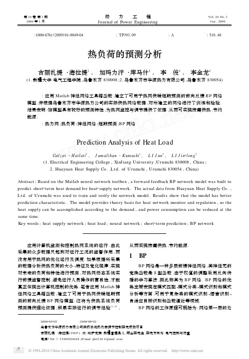
用同样的方法可预测热网的其他参数 ,如流量 、 室外温度 、供水温度等.
3 预测结果分析
由于热力系统负荷变化的复杂性 ,神经网络要 获取其变化规律 ,需要较大的训练样本. 根据乌鲁木 齐市华源热力有限公司的运行数据 ,在一个完整的 采暖期中 ,用每日前 16h 的数据作为样本 ,预测后 8h 的热量参数 (如回水温度 、流量等) . 图 3 为 B P 网 络对热网动态模型回水温度 Tg 以及流量 qm 的预 测值与实际值的比较曲线. 表 1 为乌鲁木齐市华源热力有限公司的 6 号换 热站回水温度和流量的部分仿真数据误差分析表.
40. 00
41. 363 2
1. 363 2
490
200421123
42. 50
45. 233 8
2. 733 8
485
200421124
40. 00
41. 569 4
1. 569 4
464
200421125
40. 00
41. 363 2
1. 363 2
490
200421126
42. 90
44. 063 7
图 1 神经网络辨识热网的动态系统 Fig. 1 Sketch of neural net work system for heat supply
net work dynamic identification system
报提供依据[628 ] . 图 1 为神经网络辨识热网动态系统的示意图. 其中 ,A 为被辨识的热网动态系统 ;B 为由神经网路 构成的一个辨识模型[9] ; d 为系统干扰 ,即室外温度 Tw . 图中 A 与 B 是并联的 ,将输入 x ( k) - Tg ( k) , qm ( k) 同时加到 A 和 B 上 ,测量其输出 y ( k + 1) - Th · ( k + 1) 和 ^T h( k + 1) ,并利用误差 e( k + 1) = T h ( k + 1) - ^T h( k + 1) 修正 B 的参数 ,使 e ( k + 1) 趋近于 0 , 此时辨识模型 B 能很好地近似热网动态系统 A .
电子邮件过滤算法基于反馈纠正概率学习说明书
Mail Filtering Algorithm Based on The Feedback Correction Probability LearningZou Xiao Yunhubei polytechnic institutexiaogan hubei,432000Abstract—With the popularity of the Internet, e-mail with its fast and convenient advantages has gradually developed into one of the important communication tools in people's lives. However, the problem of followed spam is increasingly severe, it is not only the dissemination of harmful information, but also waste of public resources. To solve this problem, the author proposed a mail filtering algorithm based on the feedback correction probability learning. The feedback correction probability training has less feedback learning data and use error-driven training in order to achieve a high classification effect. The experiment also tested the idea.Keywords-The feedback Probability learning; Spam; ProbabilityI.I NTRODUCTIONInternet is an international information system and brings immeasurable economic and social benefits. At the same time, it also brings some dangerous international problems, such as e-mail spam (unsolicited e-mail)[1~3]. According to " China Internet Development Statistics Report ", China's Internet users receive 13.9 e-mail weekly in July 2004: 4.6 normal e-mail, the spam has reached 9.3. Spam spread like an epidemic in network environment, affecting normal network communications, wasting network resources, so the computer users waste a lot of time in mail identification. For users, spam has brought them a lot of harm and loss in their work, income, life, entertainment and the spiritual realm[4~6].To solve this problem, this paper proposed a mail filtering algorithm based on the feedback correction probability learning. The feedback correction probability training has less feedback learning data and use error-driven training in order to achieve a high classification effect. The experiment also tested the idea. Comparing with the standard analytic hierarchy process, we know that the algorithm reduce the amount of calculation while ensure the correctness of the conclusion. It also makes weight to determine more reasonable and provides a scientific basis for further evaluation decisions.II.T HE MAIN IDEAS AND PRINCIPLES OF CORRECTION PROBABILITY ASSOCIATED ALGORITHMThe object of information filtering is the dynamic flow of information, thus the form and content of spam is changing over time, so mail filtering system needs to be updated according to the new changes and demands. So we introduce the feedback learning techniques to improve our spam filtering model, making the model realizing real-time updates based on the form and content of spam and the needs of users. The feedback technique is an important research methods, through the man-machine interactive way to make the output of the model return to the input, in order to improve the performance. It is a method to achieve optimized through learning misclassified part of the data , then re-training and learning. In general there are two typesof feedback learning: incremental learning and re-learning. The feedback learning make full use of the results or intermediate results of the original study, and generally do not need to rescan the learned mails. Re-learning is a completely re-start learning of the new study set contains thee-mail have been learned and to be learned. E-mail sets can be divided into a training set, test set and classified set. For filtering process, the e-mail can be divided into two categories: spam and legitimate mail, which useful in spam filtering applications.A.The process of learning algorithmFeedback learning algorithm of support vector machine finds points located at the boundary of the two categories and feeds back classification error messages. Model classification processing relates to support vector of classification boundary. If system classification proved it's a correct document means that original classification model contains relevant information, no value to our feedback learning. Classification error e-mail, contain classified information not included in original model, is the focus of feedback learning. But these e-mail tend to be a small part in entire classification results set. In theory, the learning method has feedback fewer samples and improves the classification accuracy. Support vector machine classification through quadratic optimization training processto get data points set used for classification process on the boundary. These points, called support vectors, including data points correctly and incorrectly classified located on classification boundary. Support vector set K is a relatively small subset of training set E, generally speaking . Support vector containing useful classified information in training document set E. Therefore, support vector machines has good incremental training learning features. Feedback learning can make full use of incremental learning advantages to re-optimize the selection of support vector setS in feedback document set F and classification model Ω, in order to gain new classification model and support set k'.1. The analysis and optimization of support feedback vector machineConstruct decision function,iskernelfunction,is supportvector,is optimal solution of dual problem. The KKT conditions eachsample satisfied is:New sample satisfy KKT conditions don't change support vector set, while others do. Samples against KKT conditions can be divided into three types:1. In classification interval, the sample and the class on the same side of classification boundary, correctly classified by original classifier, ; as S1 shown in Figure 1;2. In classification interval, the sample and the class on the different sides of classification boundary, incorrectly classified by original classifier, ; as S2 shown in Figure1;3. Outside classification interval, the sample and the class on the different sides of classification boundary, incorrectly classified by original classifier, ; as S3shown in Figure1;Figure 1 Samples against KKT conditionsThrough analysis of the samples distribution, we found that misclassification sample is a special case against KKT conditions. Therefore, we select the wrong classified ones as the feedback learning samples, so that training programs can quickly capture new information contribute to classification and timely abandon duplicate information. Here mainly for feedback processing of training documents set E, the feedback e-mail sets need to take optimization training together with the original model of support vector set. These e-mail may have become the support vector of original classification model, and their remaining in set S will affect the model results. Therefore, the feedback learning process during e-mail training, we should firstly detect the supportvector of feedback e-mail, remove the same feature vectorsand add new feature vector, before the training.B. The processes of feedback algorithmThe processes of feedback algorithm are shown as follow: Step1: Process each e-mail i d∈R in set R (set of classification results), feedback the error e-mail which also can be selected in a certain ratio, depends on our specific environment. Verify the artificial feedback classification (legitimate mail or spam) according to the e-mail characteristics, then put them into the feedback e-mail set F to prepare for the effective characteristic collection.Step2: After document feedback processing, extract the body of the e-mail, then quantification process and featureextraction. Read support vector sets (),,1,2,3......zx j j j e m h i d =, d is the number of supportvectors in the set.Step3: Begin the feedback training learning. Get a e-mail in feedback set F and generate related document vector, then obtain support vector in set S of original classification model Ω. Feedback e-mail vector:(),,1,2,3......gb gi i i f m h i n =Step4: Analysis the type of feedback document, if the e-mail is part of training document feedback mail, calculate the similarity of the feedback vector and the support vector. The distance between points in the space is measured by the cosine of the angle between the vectors, which represents the degree of similarity between documents. The smaller the angle the higher the similarity of the document.(,)gb zx i j gb zx i j gb zx i jf e sim f e f e =, if the similarity is biggerthan m θ, two e-mail are same, so delete the feedback vector. Step5: Repeat Step3, until all support vectors aredifferent from each other. These vectors form set 'k .Step6: Collect recent spam characteristic phrases, then change them into the vector model denoted as M.Step7: Take the union of F, M and 'k as training set, begin Re-optimize training of support vectors.III. E XPERIMENTAL A NALYSISFeedback learning experiment is cumbersome and also need enough experience. We use F1 as the reference, compare the difference before and after feedback. Refer to the result of support vector before feedback, final result is average of many experiments. Preliminary experiments show that the filtering effect is improved, we will do further research experiments of this algorithm to verify the result. In additional, when the files have strong compatible characteristics the manual classification standard will not as same as the practical training sample standard, which will cause the temple fluctuation in some specific type because the feedback learning needs the persons give relatedfeedback types. However, this will not affect the performance of feedback learning classification. It also indicates the importance of the quality of the learning samples for classification performance.After all, we can infer that using feedback learning techniques to re-filter the E-mail is quite reasonable method based on the performance of the feedback learning in the information filter area. It utilizes the error diver to train in order to achieve good filter performance which fulfills the function of E-mail real time update and increase the filter accuracy on the base of small amount of E-mails.IV.C ONCLUSIONSThe paper proposes a scam E-mail filter algorithm based on feedback correct probability learning techniques to fix the advantage of the standard filter models. The method, which is scientific and simple, decreases the subjective factors and provides scientific basis for the scam messages filter strategy. The model can be easily applied to other area if it is combined with computers and set up appropriate evaluation systems.A CKNOWLEDGMENTChinese book Classification Code: TP391 Document code: A.R EFERENCES[1]K.Schneider,A Comparison of Event Models for Naive Bayes Anti-Spain E-Mail Filtering[A].In: Proc.10th Conference of the European Chapter of the Association for Computational Linguistics (EACL 2003) [C].Budapest,Hungary. 2003.4:307一314.[2]S.S.Keerthi,K. Shevade,C. Bhattachayya et al. Improvements toPlatt’s SMO Algorithm for SVM Classifier Design[J]. Neural Computation . 13(3),2001.[3]Lin Chunfu,Wang Shengde.Fuzzy Support Vector Machines[J]. IEEETransactions on Neural Networks, 2002..[4]Huang Hanpang, Liu Yihung. Fuzzy Support Vector Machines forPattern Recognition and Data Mining [J]. International Journal of Fuzzy Systems, 4(3),2002.[5]Li Kunlun, Huang Houkuan. An Architecture of Active LearningSVMs for Spam. Signal Processing, 2002 6th International Conference, 2002, Vol. 2, Aug. 26-30: 1247–1250.[6]Rocchio J J. Relevance Feedback in Information Retrieval[A]. TheSmart Retrieval System Experiments in Automatic Document Processing [C]. NeJersey:P rentice Hall Inc,1971. 313-323.TABLE I. T ABLE 1:C OMPARISON OF F1 BEFORE AND AFTER FEEDBACK Corpus F1 before SVM feedback F1 after SVM feedback Ling-spam bare 86% 87.5%Ling-spam Lemn 86.3% 87.6%Ling-spam Stop 86.6% 88.3%Ling-spam Lemn_stop 87.5% 89.7%。
带状态观测器的逆变器增广状态反馈控制和重复控制

1 引言
带 LC 滤波器的逆变电源在空载时的阻尼比很 小,具有很强的振荡倾向,单独采用输出电压反馈 难以获得良好的动态性能。双环控制方式[1],通过 设置电容电流内环提高了系统的动态性能,但是双 环控制的控制器设计比较复杂,并且双环控制对控
续系统设计的模拟控制器离散化来得到数字控制
器,为模拟化方法。直接数字法就是对加采样保持
器的被控对象离散化模型进行数字控制器设计。由于
实际系统的采样频率不可能无穷大,所以模拟化方法
不能实现只有数字控制特有的控制策略。直接数字法
在保持系统稳定的同时可得到更宽的控制带宽,这个
优点在多环系统或采样周期较大时变得更为显著,所
式中
x = [uC
iL
]T
,
A
=
⎡ ⎢
0
⎢
⎢⎢⎣−
1 L
1 C −r L
⎤ ⎥ ⎥ ⎥ ⎥⎦
,
B
=
⎡ ⎢ ⎢ ⎢⎣
0 1 L
⎤ ⎥ ⎥ ⎥⎦
W
=
⎡⎢− ⎢
1 C
⎤ ⎥ ⎥
,
C = [1
0]
⎣0⎦
y—— 逆变器输出
2.2 离散时间模型
数字控制器的设计方法有模拟化方法和直接数
字化方法两种[6]。如果采样周期足够小,把基于连
第 22 卷第 1 期
刘新民等 带状态观测器的逆变器增广状态反馈控制和重复控制
93
图 2 增广状态反馈控制系统图
Fig.2 Additional state-feedback control system
- 1、下载文档前请自行甄别文档内容的完整性,平台不提供额外的编辑、内容补充、找答案等附加服务。
- 2、"仅部分预览"的文档,不可在线预览部分如存在完整性等问题,可反馈申请退款(可完整预览的文档不适用该条件!)。
- 3、如文档侵犯您的权益,请联系客服反馈,我们会尽快为您处理(人工客服工作时间:9:00-18:30)。
A feedback-based model for I/O servicingAthena Vakali *,G.I.Papadimitriou,A.S.PomportsisDepartment of Informatics,Aristotle University of Thessaloniki,P.O.Box 114,54006Thessaloniki,GreeceReceived 22February 2000;accepted 3May 2000AbstractModern I/O subsystems have increased their capacity and density but their performance has not been improved accordingly.To address this problem,we have developed a new model that is based on the feedback information provided to the I/O subsystem controller.The presented model is applied to a multiple disk drive subsystem,which serves requests in parallel.Under conventional servicing,each request refers to a speci®c drive and is placed on the corresponding disk drive queue in order to be serviced.The proposed feedback-based model redirects requests among disk drives towards performance gain.The feedback is evaluated by a metric identi®ed by the queue length per disk drive.Performance analysis proves that the feedback-based model results in e ective and improved load distribution.The request servicing in a parallel disk drive subsystem is simulated and simulation runs measure both conventional and feedback-based servicing.The simulation results validate the presented model and prove that it shows an impor-tant improvement in both seek and servicing times compared with the conventional request servicing model.Ó2001Elsevier Science Ltd.All rights reserved.Keywords:Load balancing;I/O subsystems;Parallel I/O;Secondary storage;Parallel disks performance1.IntroductionStorage subsystems are a vital component of modern computer systems.According to Ref.[5],the amount of storage sold has been almost doubling each year,and in this context,magnetic disks are the most dominant devices.Typical accesses to disks are much more slower than accesses to the main memory of a computer system.This fact has created the so called access gap ,which has gained a lot of attention and raised several issues regarding methods to overcome or to *Corresponding author.Tel.:+30-31-99-8415;fax:+30-31-99-8419.E-mail addresses:avakali@csd.auth.gr (A.Vakali),gp@csd.auth.gr (G.I.Papadimitriou),apombo@csd.auth.gr (A.S.Pomportsis).0045-7906/01/$-see front matter Ó2001Elsevier Science Ltd.All rights reserved.PII:S0045-7906(00)00027-6310 A.Vakali et al./Computers and Electrical Engineering27(2001)309±322minimize the di erence between processor speed and disk servicing time.As a consequence of the slow service time of secondary storage media,many applications become I/O bound and the storage system is often a bottleneck in many applications.The expansion of the distributed systems resulted in increased I/O requirements for parallel and distributed applications and the operating systems design has to deal directly with the I/O bottleneck[7,5].The most widely adopted solution to the I/O bottleneck problem is the use of storage subsystems with parallel functionality and capabilities.Multiple disks are used in parallel in order to increase data availability and data access parallelism.Data redundant storage has been implemented by several multiple disk schemes attached to one or more controllers and supported by identical or various disk drive con®gurations.Redundant inexpensive/independent disk arrays(RAID)have been proposed as a varying level methodology for disk redundancy [3,15].A considerable interest has been shown for the shadowed/mirrored disks(mirroring cor-responds to the RAID level1model),where all disks are identical and store the same data.In such systems,enhanced fault tolerance and improved disk performance are achieved at the ex-pense of storage space.In Refs.[1,2,8],analytic models have been developed in order to study the performance of shadowed/mirrored disks by the consideration of expected involved times, focusing on seeking.Storage system management is a major problem a ecting the overall functionality of the cur-rent systems and several approaches have been proposed towards a self-managing storage system. As indicated in Ref.[13]a self-con®guring,self-managing storage system is given and the goals of the system and speci®cations of the workload,the data and the storage devices are available and it decides on how to balance the load and the data among the disk drives.Storage management models have also been developed by identifying the attributes of the workload and/or the disk device(e.g.[6]).These attributes refer to the workload response times,bandwidth,data sizes and so on.Modern disk drives attributes and its characteristics have been identi®ed in Ref.[12]and their inclusion to the simulation model is discussed.Some of these attributes have been studied extensively in order to investigate their impact on the disk's servicing time(e.g.,the rotational delay[9]).Furthermore,the a ect of disk drives characteristics on storage performance has been investigated in connection with the advances in disk technology and the most signi®cant per-formance factors have been indicated in Ref.[10].Furthermore,modern I/O subsystems are reinforced with quite e cient mechanisms imple-mented as policies that perform scheduling,reordering of I/O requests or read-ahead.The current complicated storage systems infrastructure hardens the development of analytic as well as simulation models.Disk controller has been considered as the most suitable component for hosting storage systems policies and current technology provides e cient controllers with re-spect to the disk drive's functionality.Most disk controllers are reinforced with self-managing techniques through standard interfaces used on standard systems without software modi®ca-tions[4].This paper presents a model in solution to the problems of I/O bottleneck and I/O request servicing,as studied in Ref.[16].Our approach is based on the following important assump-tions:·most current storage systems support multiple drives and a queue of requests is associated with each drive,A.Vakali et al./Computers and Electrical Engineering27(2001)309±322311·the response time could be improved by redirecting requests to idle drives or to drives with lighter load,·the information provided by each disk drive's queue could be used as a feedback in order to perform the request redirection,·the storage system could be self-managed and the workload could be served more e ciently.The remainder of the paper is organized as follows:Section2presents the multiple disks I/O storage subsystem con®guration and identi®es the most crucial performance factors.Section3 introduces the proposed feedback model and analyzes the request servicing policies as well as the performance metrics and their impact on improving the storage system responsiveness and functionality.In this section performance analysis is carried out and theorem proofs are provided.Section4presents the simulation results and discusses the performance gain in the presented model.Finally,conclusions are summarized and future work areas are suggested in Section5.2.I/O subsystem with multiple disksSeveral I/O subsystems have been suggested in modern parallel and distributed systems.Most of these assumes the hierarchical memory model proposed in Ref.[17],where an abstract machine consists of a set of processors interconnected via a high-speed network and each processor access an appropriate I/O controller.Each of these controllers manages a set of disk drives.The con-troller is responsible for managing and directing read/write requests to the queues of the disk drives.Most modern magnetic disks have an embedded small computer systems interconnect (SCSI)controller.Here,we concentrate on a multiple disks subsystem where disk drives are managed by a common I/O controller.Disk drives are of the same type and have similar con-®guration requirements(Fig.1).2.1.Device and workload characteristicsA typical data storage hierarchy includes main memory,magnetic disks and possibly tape drives or tertiary storage devices.The host operating system guides an I/O request to the disk drive controller via the appropriate disk drivers.The controller manages the storage and re-trieval of data to and from the disk mechanism and performs mappings between incoming logical addresses and the physical disk location that stores the data[12].The storage subsystem comprises of N individual disk drives,which stores information and each one is considered as an independent drive.Each disk drive is equipped with one read/write head per disk surface and the head moves to the appropriate cylinder location in order to serve the current request.Reading data is satis®ed by accessing the disk which contains the requested data whereas writing is performed by the disk speci®ed by the®le system(as explained next).Disks serve requests in parallel in order to exploit the system's responsiveness.Disk drives have associated queues that contain requests waiting to be serviced.Current controller interfaces support commandqueueing,which permits the reordering of queued requests in order to improve disk perfor-mance(e.g.,SCSI-2).Requests arrive to the system randomly by various independent processes.Some requests arrive, while others are being serviced,and so queues are created in each disk drive.Requests arrival rate could be either constant or independent and exponentially distributed or bursty.The disk con-troller commands the drives to serve the requests posed by the®le system.A typical request consists of the following attributes:Device:the id of the disk drive to serve the request,Operation:either R(ead)or W(rite),Start Location:the physical address where the data are(will be)located,Size:the amount of data(in MBytes)to be read(written),Arrival Time:the time when the request arrived at the controller.According to the above request pattern,the controller will direct each request to the appropriate drive in order to be served.As depicted in Fig.1,each disk drive in the subsystem is an individual server''and has its own queue.Therefore,the disk controller is the common server whose service is required by all I/O operations.2.2.Performance metricsGiven the arrangement of disk surfaces and read/write heads,the time required for a particular I/O operation involves mainly the following actions(Fig.2)[10]:·wait in queue:time spent in queue waiting for the drive to be free for servicing the I/O,·wait for channel:time spent waiting for the channel to be free such that the seek and sectorinformation can be sent down,·seek time:time spent to move the appropriate head to the appropriate cylinder,·latency time:time spent for the required sector to rotate around to the location of the head,·transfer time:time to perform the actual data transfer.Disk performance is measured by speci®c metrics based on the above times spent at each phase of the request servicing process.The overall time for executing and completing a user request consists of command overhead,seek time,rotational delay and data transfer mand overhead has been reducing due to the acceleration of disk controller's chips and mechanisms.Therefore,the service time of a request in the disk mechanism is a function of the seek time (ST),the rotational latency (RL)and the transfer time (TT),whereas queue delay must be considered also for the evaluation of the overall service time [13,14].The most widely used formula for evaluating the expected service time involves these time metrics and is expressed by:E ServiceTime E ST E RL E TT ; 1 where E ST refers to the expected seek time,E RL refers to the expected rotational delay and E TT refers to the expected transferring time.Seeking is a major performance factor and several expressions have been suggested for the expected seek time evaluation.While seeking,the read/write head arm is involved in the opera-tions of speedup,coast,slowdown and settle,successively in order to reach the requested location.The speedup time will be the dominant factor for short seeks,whereas the coast is the dominant factor for long seeks.The following function has been used widely for the approximate evaluation of the seek time:Seek Time dist 0if dist 0a b dist p if 0<dist <cutoff ;c d dist if dist P cutoff 8<: 2where a ,b ,c ,d and cut-o are device-speci®c parameters and dist is the number of cylinders to be traveled.Furthermore,a closed formula has been derived for the expected seek time (E ST )under random uniform access [13].The expected rotational delay is evaluated by E RL % Revolution Time =2 for randomly distributed requests.The transfer time depends on the amount of data to be transferred and is evaluated by E [TT] Request Size =Transfer Rate under a constant TransferRate.3.The feedback model3.1.The request servicing processOur work is based on the idea of redirecting requests at the disk controller,based on provided feedback in order to improve disks performance.Controller is suggested as a better suited place for the task of reorganizing data[4].Here,the controller does not remain a static design,where data are placed as directed by the®le system.Instead,the controller becomes a dynamic tool which e ciently re-directs the requests to the physical medium according to the feedback information.Fig.3presents the structure of our feedback-based model,which revises the basic multiple disk drives model(presented in Fig.1) according to the proposed feedback.Each request is either a read or a write process guided to the controller.Our model is based on the distinction of the requests by their type(Read or Write).The feedback information is used in order to redirect the write requests from heavy loaded disk drive queues to other disk queues which remain idle or are lightly loaded.As presented in Fig.4,the feedback-based controller alters the original request pattern such that the attributes of device and start location are adapted to the systems load in case of writing.Therefore,write service is per-formed by redirecting request pattern within the controller to allow data relocation such that the service time is improved.3.2.The probability updating schemeAt each time slot t,the feedback-based controller contains a probability distribution P(t)over the set of disks.Thus,P t f p1 t ;...;p N t g,where N is the number of disks.The destination-disk of each newly arriving write request is randomly selected according to the probability dis-tribution P(t).The probability distribution P(t)is updated at each time slot by taking into accountthe estimated load of each disk drive.The load is estimated by using the disk queue length since the queue size is an indicative quantity for the disk load.De®nition.The load L i (t )of each disk d i (i 1;...;N )is evaluated in byL i t max f Q i t ; g ; 3 where Q i (t )is the number of requests waiting in the queue of disk d i ,while is a positive real number in the neighborhood of 0.The probability p i (t )of redirecting a write request to a disk d i is inversely proportional to the load L i (t )of this disk.At any time slot t ,for any two disks d i and d j ,we havep i t p j t L j t L i t A p i t p j t L j t L i t : 4 Since the choice between two disks i and j for servicing a write request will be made according to their loads L i t and L j t .The disk with the heavier load has smaller probability than the other disk with the lighter load.Since at any given time slot t ,it holds P N i 1p i 1,we express all p i s i 1;2;...;N )in terms of one speci®c disk,namely the i disk drive.Therefore,p 1 t p i tL i t L 1 t ;p 2 t p i t L i t L 2 t;...p n t p i t L i t L N t : 5From the above,we derive that the choice probability of each disk d i i 1;...;N will be updated according to the following probability updating scheme:p i t1L i tP Nk 11L k t: 63.3.Asymptotic analysisThe performance evaluation is based on the request servicing process and the probability up-dating scheme as discussed in the previous subsections.The following theorem is indicative for the proposed load-balancing model.Theorem.When the feedback-based model is used in a multiple disk system,there is a small slot size, such that for any two disks d i and d jlim t3I L i t limt3IL j t :Proof.For any two disks d i and d j,we de®ne:X i;j t L i t ÀL j t .Without loss of generality, assume that L i t >L j t .Let a be the overall arrival rate of the disk system(in requests/slot)and b is the service rate of each disk(in requests/slot).Since the disks are of identical con®guration b remains the same for all disks.a and b can be as small as desired by selecting a small slot size.We haveE D X i;j t E X i;j t 1 ÀX i;j t ;ap i t Àb À ap j t Àb ;a p i t Àp j t ;a1L i tÀ1L j t P Nk 11L k t;ÀaL i t L j tP Nk 11L k tX i;j t ÀrX i;j t ;7whereraL i t L j tP Nk 11L k t:Thus,E X i;j t 1 1Àr X i;j t : 8 Since r>0,it follows that:E X i;j t 1 <X i;j t : 9 316 A.Vakali et al./Computers and Electrical Engineering27(2001)309±322Furthermore,if we select a small enough slot size,such that a <L i t L j t P N k 11=L k t and consequently,r <1,we haveE X i ;j t 1 >0: 10 From relations (9)and (10),it is derived that ÀX i ;j t 1 is a submartingale [11]and consequently,it asymptotically converges to a random variable ÀX .Therefore,as t 3ID X i ;j t 30A a p i t Àp j t 30A L i t ÀL j t 30:11 Thus,lim t 3I L i t lim t 3IL j t :4.Simulation resultsWe have built an event-based simulator to validate the feedback-based I/O servicing model.In order to study the performance of the proposed model,we have implemented the conventional model and two types of models for the feedback-based model,namely the deterministic and the probabilistic model.According to the deterministic model,requests are redirected by deter-mining the minimum loaded disk (used as feedback)each time,whereas under the probabilistic model the disk choice depends on the disks probability distribution (as described in the previous section).Each simulation run considered arrivals of more than 500,000requests over the simulated time.The simulation model was studied for an I/O subsystem of 2;4;...;10disk drives.Each disk is con®gured by the characteristics proposed in Refs.[12,13]for the HP 97560disk drive.The workload is characterized by the arrival process,the request rate,bursty arrivals and the fraction of read and write processes.The read/write ratio was also a parameter for the simulation process and there are di erent arrival sets depending on the probability of having reads to vary within the range 0:1;...;0:9.The proposed feedback-based model showed to be bene®cial in all cases when compared to the conventional I/O servicing model.Figs.5and 6present the improvement rates of the deterministic and probabilistic over the conventional model,respectively.These rates refer to the improvement in service time as evaluated by Eq.(1).The curves represent the results when reading probability was 0.1,0.3,0.5,0.7,0.9,under I/O subsystems of 2,4,6,8,10disk drives.As it was expected from the performance analysis,the most bene®cial improvements in service time result when having low read ratio and many parallel disk drives,since there is an increased exploitation of the service parallelism and load balancing.More speci®cally,the improvement rates for the deter-ministic over the conventional model vary between 4%(2disks,0.9read ratio)and 19%(10disks,0.1read ratio),whereas the corresponding improvement rates for the probabilistic over the conventional model vary between 5%(2disks,0.9read ratio)and more than 20%(10disk,0.1read ratio).Seek time shows a similar improvement rate of the feedback-based model compared to the conventional one.Similarly,Figs.7and 8present the seek time improvement rates of the A.Vakali et al./Computers and Electrical Engineering 27(2001)309±322317deterministic and probabilistic over the conventional model,respectively.The improvement rates for the deterministic over the conventional model vary between 6%(2disks,0.9read ratio)and 18%(10disks,0.1read ratio),whereas the corresponding improvement rates for the probabilistic over the conventional model vary between 7%(2disks,0.9read ratio)and more than 22%(10disks,0.1read ratio).Figs.9and 10depict the load distribution under indicative loads serviced by both the con-ventional and the proposed feedback-based probabilistic model.More speci®cally,Fig.9depicts the load distribution for a parallel I/O subsystem of 10disk drives,under both the feedback-based and the conventional model under 0.1read ratio and Fig.10presents the same bars for a 0.7read ratio.These histograms depict the load variation for each of these models and they represent the bene®cial load distribution of the proposed feedback-based model.Thefeedback-based model exploits the disks with low loads and improves the overall requests ser-vicing process.5.Conclusions ±further researchThe presented paper provided a new I/O servicing model in a parallel multiple I/O subsystem.The proposed model has introduced a request servicing redirection,based on disk queue infor-mation used as feedback.The redirection concerns write requests and the I/O controller is re-sponsible for the new model implementation.The performance analysis proves that the proposed model improves the I/O servicing process and this is also documented by a developed simulation model.Simulation runs for heavy disk loads have been presented and indicative results aredemonstrated.Both service and seek times are considerably bene®ted by the feedback-based model at rates over than 22%.Future work could expand this model in order to include di erent disk technology con®gu-rations.This expansion could be quite useful for investigating the in¯uence of disk parameters to the feedback-based processing.Also,we could adopt di erent load estimations such as expected seek or rotational delays at the disk queues.Disk caches could also be added to the model structure in order to further study the caching in¯uence to the I/O servicing performed under the proposed feedback-based model.References[1]Bitton D,Gray J.Disk shadowing.Proceedings 14th VLDB Conference.1988.p.331±38.[2]Bitton D.Arm scheduling in shadowed disks.Proceedings IEEE COMPCON 89Conference.1989.p.132±36.[3]Chen P,Lee E,Gibson G,Katz R,Paterson D.RAID-high performance,reliable secondary storage.ACM Computer Surveys 1994;26(2):145±85.[4]English R,Stepanov A.Loge:a self-organizing disk controller.HPL-91-179,HP Labs,Technical Report.1991.[5]Gibson GA,Vitter JS,Wilkes J,et al.Strategic directions in storage I/O issues in large-scale computing.ACM Computer Surveys 1996;28(4):763±79.[6]Golding R,Shriver E,Sullivan T,Wilkes J.Attribute-managed storage.Hewlett-Packard Laboratories,Technical Report HPL-SSP-95-11,Storage Systems Program.1995.[7]Jain R,Werth J,Browne JC,editors.Input/output in parallel and distributed computer systems.Dordrecht:Kluwer Academic Publishers,1996.[8]Lo RW,Matlo NS.Probabilistic limit on the virtual size of replicated disc systems.IEEE Trans on Knowledge and Data Engineering 1992;4(1):99±102.[9]Ng SW.Improving disk performance via latency reduction.IEEE Trans on Computers 1991;40(1):22±30.[10]Ng SW.Advances in disk technology-performance issues.IEEE Computer 1998;31(5):75±81.[11]Tucker H.A graduate course in probability.New York:Academic Press;1967.[12]Ruemmler C,Wilkes J.An introduction to disk drive modeling.IEEE Computer 1994;27(3):17±28.[13]Shriver E.Performance modeling for realistic storage devices.PhD Thesis,Department of Computer Science,New York University,1997.[14]Shriver E,Merchant A,Wilkes J.An analytic model for disk drives with readahead caches and request reordering.ACM SIGMETRICS'98,Conference Proceedings.1998.p.182±91.[15]Wilkes J,Golding R,Staelin C,Sullivan T.The HP AutoRAID hierarchical storage system.ACM Trans on Computer Systems Feb 1996;14(1):108±36.[16]Vakali A,Papadimitriou GI.An adaptive model for parallel I/O processing.Proceedings of the IASTED International Conference.Parallel and distributed systems (PDCS'99)1999.p.13±42.[17]Vitter J,Shriver E.Algorithms for parallel memory I,II.Department of computer science,Brown University,Technical Report CS-90-21.1990.Athena I.Vakali received a B.S.degree in Mathematics from the Aristotle University of Thessaloniki,Greece and an M.S.degree in Computer Science from Purdue University,USA.In 1997,she received a Ph.D.degree in Computer Science from the Aristotle University of Thessaloniki.Since 1997,she is a Lecturer at the Department of Informatics,Aristotle University of Thessaloniki,Greece.Her research interests include de-sign,performance and analysis of storage subsystems and data placement schemes for multimedia and Web based information.She has published several papers in international journals and conferences.A.Vakali et al./Computers and Electrical Engineering 27(2001)309±322321Georgios I.Papadimitriou received the Diploma and Ph.D.degrees in Computer Engineering from the Uni-versity of Patras,Greece in 1989and 1994,respectively.From 1989to 1994,he was a Teaching Assistant at the Department of Computer Engineering of the University of Patras and a Research Scientist at the Computer Technology Institute,Patras,Greece.From 1994to 1996,he was a Postdoctorate Research As-sociate at theComputer Technology Institute.Since 1997,he has been a Lecturer at the Department of Informatics,Aristotle University of Thessaloniki,Greece.His research interests include design and analysis of broadband networks and learning automata.He has published several dozens of papers in international journals andconferences.Andreas S.Pomportsis received a B.S.degree in Physics and an MS.degree in Electronics and Communi-cations (both from the University of Thessaloniki),and a Diploma Degree in Electrical Engineering from the Technical Universityof Thessaloniki.In 1987,he received a Ph.D.degree in Computer Science from the University of Thessaloniki.Currently,he is a Professor in the Department of Informatics,Aristotle Universityof Thessaloniki,Greece.His research interests include computer architecture,parallel and distributed com-puter systems,and multimedia systems.322 A.Vakali et al./Computers and Electrical Engineering 27(2001)309±322。