QS5AA030M说明书
西格玛安全截止阀S 50产品信息说明书

Safety Shut-Off ValveS 50Product informationAC Accuracy classAG o Upper response pressure group AG u Lower response pressure group BV Breather valveGPR Gas pressure regulator HDS High-pressure spindle K G Valve flow rate coefficient p Pressure p d Outlet pressure p df SRV closing pressure p do SRV opening pressure p ds Setpoint of the response pressurep ds oUpper SSV response pressure p ds u Lower SSV response pressure p f,max Maximum closing pressure PS Maximum allowable pressure p u Inlet pressureQ n Standard volumetric flow rate RE Diaphragm assembly RSD2 Throttle valveSSV Safety shut-off valve SRV Safety relief valveSG Closing pressure group t Gas Gas inlet temperature VS Valve seatw d Outlet gas velocity w uInlet gas velocityW ds o Upper spring adjustment range (SSV)W ds u Lower spring adjustment range (SSV)Δp Pressure difference from inlet pressure to outlet pressure Δp wo Min. re-engagement difference between upper response pressure and normal operating pressure Δp wu Min. re-engagement difference between lower response pressure and normal operating pressure ρn Gas densityTable of ContentsApplication, Characteristics, Technical Data 4Application 4Characteristics 4Type of models / Options (see page 10) 4Technical data 5Structure and function 6Sectional view 7SSV setpoint spring table - control device 8Dimensions, Connection, and Weight 9Dimensional drawing 9Dimensions and weight 9Connection of the measuring lines and breather lines 9Types of Models / Options 10Design 11Properties of Gases 11Order Data 12Notes 13Contact 14Notes 16Observe the following publications in relation toinstallation, start-up and maintenance: DVGW - work sheets G 491 and G 600Operating and Maintenance Instructions S50ATTENTION List of abbreviations and formula symbolsApplication, Characteristics, Technical DataApplicationSafety shut-off valve (SSV), direct-acting (operating without auxiliary power), for systems acc. to DVGW work sheets G 491 (A) and G 600 (A) (TRGI)Can be used for the gases defined in DVGW work sheet G 260 / G 262 and neutral non-aggressive gases. (other gases on request)Characteristics• Integral pressure-tight version (IS)• High flow rate capacity• Open-air model• with BV breather valve• with electric position indicator SSV 'Closed' via inductive proximity initiator or via reed contact • with SSV electromagnetic remote release when power is applied or in case of power failure• with SSV manual release• oxygen model• hydrogen modelResponse pressure groupsLower response pressure AGu incommand area wdsu AG U Upper response pressure group AGoin command area wdsoAGo10 mbar to 50 mbar2050 mbar to 500 mbar10> 50 mbar10> 500 mbar5 Type of models / Options (see page 10)Technical dataType S 50ModelIntegral pressure-tight (IS)Max. allowable pressure PS 3 barNominal width Rp 1“ (DN 25), Rp 1½“ (DN 40), Rp 2“ (DN 50)(NPT thread on request)Standard volumetric flow rate Q n,max Rp 1“: 100m³/h, Rp 1½“: 300m³/h, Rp 2“: 300m³/h Type of connection Internal thread acc. to EN 10226-1MaterialHousing / actuator housing/ Control device housing Al cast alloy DIN EN 1706-AC-42100 ST6Corrosivity categoryDIN EN ISO 12944-2C1 to C5-I without additional coatingsC5-Man epoxy resin coating is recommended (see page10)Temperature range, Class 2-20°C to +60°C (operating/ambient temperature)Function, strength and tightness DIN EN 14382CE mark acc. to PED/ PIN number C E -0085-BS0420Ex protection The mechanical parts of the device do not have anypotential ignition sources of their own and therefore do not fall within the scope of ATEX 95 (94/9/EC). Electrical components fitted to the devicecomply with the ATEX requirements.Preferred installation positionThe safety shut-off valves (SSV) shall be installed in the pipeline preferably in horizontal position. For all nominal widths, the direction of flow is indicated by an arrow on the housing.Note: Observe the following documents in relation to installation, start-up, and maintenance:• DVGW - work sheets G 491 and G 600• Operating and Maintenance Instructions S50Installation upside down only after consultation with Medenus GmbHStructure and functionThe safety shut-off valve S 50 shuts off the gas flow when the outlet pressure in the regulation section exceeds or falls below a certain response pressure. To this end, the outlet pressure to be monitored is passed on to the SSV control device via a separate measurement line. As a function of the change in pressure, the diaphragm in the control device is raised or lowered. When the outlet pressure in the regulation section falls below the lower switch-off point or exceeds the upper switch-off point, the switch socket connected to the SSV diaphragm will move to the corresponding disengaging position, the balls of the engaging mechanism will release the SSV screw spindle, and the closing spring will press the SSV valve plate against the valve seat. The SSV actuator shuts off the gas flow gas-tight.The SSV can only be opened by hand and engaged in the open position. To do so, the outlet pressure at the measuring point must be lowered below the upper response pressure or raised above the lower response pressure by at least the re-engaging differential amount (Δp).The SSV can, except where otherwise stipulated in specific national legislation, be used in either functional class A (with diaphragm rupture protection) or B (without diaphragm rupture protection).There is also the option of using a remote display for the SSV position “CLOSED” and a manual and remote release when power is applied or in case of power failure.Installation exampleP 1P 2m in . 5x D NInlet OutletRange formeasuring points*(approx. 3x DN P 2)*) Recommended max. velocity at the measurement line port 25 m/sKSN75DF100S50SL10R50Sectional viewActuator housingValve seatActuatorBall detentRe-engagement unitDiaphragmSetting screw for lowerresponse pressureSetting screw for upperresponse pressure*) Standard spring**) If the control device is set up for simultaneous monitoring of upper and lower response pressures, the differencebetween the setpoints for the upper and lower response pressures (pdso and pdsu) should be at least 10% greater than thetotal of values given for Δpwo and Δpwu.SSV setpoint spring table - control deviceB ALYDimensions, Connection, and WeightDimensional drawingConnection of the measuring lines and breather linesNominal width MeasurementlineBreather lineDN 025 Rp 1“Connection* for: tube 12 x 1.5 (thread G 1/4)DN 040 Rp 1½“DN 050 Rp 2“Reactivation of SSVDimensions and weightInductivetransmitterSignal transmitterTypes of Models / OptionsSSV manual and remote releaseReed contacts and inductive transmittersare used to monitor the position (closed oropen position) of the safety shut-off valvevia remote display.Reed contact / inductive transmitterThe direct-acting safety solenoid valve is used aselectromagnetic remote release for closing the safetyshut-off valve when power is applied or in case of powerfailure.To protect the gas pressure regulator from externalinfluences, starting from a corrosivity category C5-M werecommend an epoxy resin coating.Epoxy resin coating in RAL colorsTypes of modelsOxygen version O2Hydrogen version H2(with helium leak test)The BV breather valve is used as for securing the installationroom against inadmissible escape of gas from diaphragmcomparator compartments of safety shut-off valves. In case ofa defect, the impermissible escape of gas into the surroundingatmosphere is limited to a maximum of 30l/h (air).It also serves as a substitute for an expensive and complexinstallation of breather lines.(Option not available for hydrogen version H2)BV breather valve BV breather valveDesignExample:Checking the gas velocitiesw = 380 ∙ Q n / (DN² ∙ p abs )Note: The factor 380 refers to an operating gas temperature fromapprox. 15°C to 20°C. For other temperatures, the velocity must be corrected as follows: w corr = w ∙ (t gas + 273.15) / 290Recommended max. gas velocity at the inlet flange:50 - 70 m/s Lower value for redirections upstream of the SSVInlet and outlet nominal width of the pipeline according to the selected device: 25 mm Q n = 70m³/h p u / (p d ) = 5 bar w u = 380 ∙ 70 / (25² ∙ 6) = 7.1 m/sDetermining the upper response pressureOutlet pressure P d(mbar)Upper response pressure W dso≤200P d +100 mbar >200 - ≤800P d x 1.5>800 - ≤1600P d x 1.3>1600P d +500 mbarPressure loss formulaCalculation pressure absolute (p u +1 bar)= p u,absΔp = Q nK Gx1000p u,abs2Properties of Gases• for natural gas (ρn = 0.83 kg/m³; t = 15°C)•f - natural gas conversion factor- LGas f Hs,n Gas f Hs,n [kWh/m³] [kWh/m³]Acetylene 0.84 16.25 Sewage gas 0.84 Ammonia 1.04 4.83 Carbon monoxide 0.81 3.51Butane 0.55 37.23 Carbon dioxide 0.65 -Chlorine 0.51 - Air 0.80 -Landfill gas approx. 0.80 Methane 1.08 11.06Natural gas L 1.00 9.77 Propane 0.64 28.03Natural gas H 1.03 11.45 Oxygen 0.76 -E thane 0.78 19.55 Sulphur dioxide 0.53 -E thylene 0.97 16.516 Nitrogen 0.81 -Mine gas (30% CH4) 0.86 Hydrogen 3.04 13.43Helium 2.15 -Order DataSafety shut-off S50/Rp1“/MD-R/left/BV/N/H/WAZ/SoIn every selection group, only one option can be selected in each case.............................................................................. ............................................................................. ............................................................................. ............................................................................. ............................................................................. ............................................................................. ............................................................................. ............................................................................. ............................................................................. ............................................................................. ............................................................................. ............................................................................. ............................................................................. ............................................................................. ............................................................................. ............................................................................. ............................................................................. ............................................................................. ............................................................................. ............................................................................. ............................................................................. ............................................................................. ............................................................................. .............................................................................If you want to know more about solutions from MEDENUS for the gas industry, please contact your local contact person or go to our internet site at www.medenus.de Trade representation worldwide medenus.de/de/kontakt.htmlManagementALEXANDER CHRISTIANI Phone: +49 (0) 2761 / 82788-18Mail:***********************Head of Sales & Marketing FRANZ FEICHTNERPhone: +49 (0) 2761 / 82788-26Mobile phone: +49 (0) 151 / 51002711Mail:**********************Technical Inside Sales Department MINDAUGAS PECKAITISPhone: +49 (0) 2761 / 82788-23Mail:**********************Inside Sales Department SEBASTIAN HUCKESTEINPhone: +49 (0) 2761 / 82788-11Mail:***********************MEDENuSGas-Druckregeltechnik GmbHIm Langen Feld 3D-57462 Olpe Phone: +49 (0)2761 82788-0Fax: +49 (0)2761 82788-9Mail:***************Internet: www.medenus.deInside Sales Department STEFANIE MÜLLERPhone: +49 (0) 2761 / 82788-13Mail:********************Head of Inside Sales Department MANUEL SCHEPPPhone: +49 (0) 2761 / 82788-20Mobile phone: +49 (0) 170 / 6355309Mail:*******************Notes .............................................................................. .............................................................................. .............................................................................. .............................................................................. .............................................................................. .............................................................................. .............................................................................. .............................................................................. .............................................................................. .............................................................................. .............................................................................. .............................................................................. .............................................................................. .............................................................................. .............................................................................. .............................................................................. .............................................................................. .............................................................................. .............................................................................. .............................................................................. .............................................................................. .............................................................................. .............................................................................. ..............................................................................Deutsch:http://medenus.de/files/upload/downloads/S50/Pi_S50_de.pdfEnglish:http://medenus.de/files/upload/downloads/S50/Pi_S50_en.pdfIn the download area of our homepage, this document is available in different languages. You can use the following QR codes and links to go directly to this document in your language.MEDENuS Gas-Druckregeltechnik GmbH Phone +49 (0)2761 82788-0Fax +49 (0)2761 82788-9Im Langen Feld 3 / D-57462 Olpe***************www.medenus.de。
综合电量变送器使用说明书
综合电量变送器使用说明书标题:综合电量变送器使用说明书一、产品介绍综合电量变送器是一种将被测信号转换为标准电流信号或电压信号的设备,广泛应用于电力系统、自动化控制等领域。
本产品具有精度高、稳定性好、抗干扰能力强等特点。
二、技术参数1. 输入范围:AC 0-5A/0-1A,DC 0-20mA/4-20mA2. 输出范围:DC 4-20mA/0-5V/0-10V3. 精度等级:0.5%4. 工作温度:-25℃~70℃5. 存储温度:-40℃~85℃6. 相对湿度:≤95%(无冷凝)三、操作步骤1. 将变送器接入电源,并确保输入信号在规定的范围内。
2. 根据需要选择输出信号类型(电流或电压)。
3. 使用万用表检查输出信号是否正常。
四、注意事项1. 在安装和使用过程中,应避免强烈震动和冲击。
2. 请勿在潮湿、腐蚀性气体环境中使用。
3. 长期不使用时,应断开电源,存放在干燥、通风的地方。
4. 不得私自拆卸和维修,如有问题,请联系专业人员处理。
五、故障排除如果设备出现故障,首先检查电源和输入信号是否正常,然后按照以下步骤进行排查:1. 检查接线是否正确。
2. 检查变送器的工作环境是否符合要求。
3. 如果以上方法不能解决问题,请联系我们的售后服务部门。
六、联系方式如需了解更多关于综合电量变送器的信息,或有任何疑问和建议,欢迎随时联系我们:电话:XXX-XXXX-XXXX邮箱:***************感谢您选择我们的综合电量变送器,我们将竭诚为您服务!【注】此文档仅供参考,具体操作请参照实物设备及详细的产品手册。
GTAS-30A、50A驱动器说明书
1
第 1 章 产品检查与安装
伺服驱动器附近有干扰设备时,对伺服驱动器的电源线以及控制 线有很大的干扰影响,使驱动器产生误动作。可以加入噪声滤波 器以及其它各种抗干扰措施,保证驱动器的正常工作。注意加入 噪声滤波器后,漏电流会增大,为了避免这个毛病,可以使用隔 离变压器。特别注意驱动器的控制信号线很容易受到干扰,要有 合理的走线和屏蔽措施。
5
2.4 标准连接
z 位置控制
第 2 章 接线
6
交流伺服驱动器使用手册
第 3 章 接口
3.1 GTAS-30A 驱动器电源端子 TB
表 3.1 电源端子 TB
端子号 端子记号 信号名称
功能
1
PE
系统接地
接地端子
2
R
主回路电源输 主回路电源输入端子
3
S
入三相
AC220V 50Hz
4
T
AC220V
注意:不要同电机输出端子 U、V、W 连接。
COIN ON:当位置偏差计数器数值在 设定的定位范围时,定位完成输出 ON (输出导通),否则输出 OFF(输出截 止)。
输出;(速 -
速度到达输出端子。
度控制方
COIN ON:当速度到达或超过设定的
式下)
速度时,速度到达输出 ON(输出导 通),否则输出 OFF(输出截止)。
10
交流伺服驱动器使用手册
蔽此功能,用户不用连此端子,
也能使 CCW 驱动允许。
8
交流伺服驱动器使用手册
13 CW 驱 动 RSTP Type1 CW(顺时针方向)驱动禁止输入端子。
禁止
RSTP ON :CW 驱动允许,电机可以
PMC-550A低压电动机保护控制器用户说明书_V2.6_131106
PMC-550A低压电动机保护控制器用户说明书(V2.6)(版权所有,翻版必究)PMC-550A用户说明书版本V2.6危险和警告本装置只能由电气专业人士进行安装,对于因不遵守本手册的说明所引起的故障,厂家将不承担任何责任。
触电、燃烧或爆炸的危险⏹装置只能由取得资格的电气工作人员才能进行安装和维护。
⏹更换装置前,应注意断开交流电压输入和装置电源,注意电流传感器的二次绕组不可短路。
⏹要用一个合适的电压检测装置来确认电压已切断。
⏹在将装置通电前,应将所有的机械部件,盖子和端子等恢复原位。
⏹装置在使用中应施加正确的电压。
不注意这些预防措施可能会引起严重伤害。
本装置设置缺省密码:0000。
本说明书版权属深圳市中电电力技术股份有限公司所有,未经书面许可,不得复制,传播或使用本说明书及其内容,违犯者将要对相关损失负责。
深圳市中电电力技术股份有限公司保留所有版权。
我们已经检查了本说明书描述硬件和软件内容的准确性。
由于不可能完全消除差错,所以我们不能保证完全正确。
本说明书将被定期升级,升级的说明书会做必要的修改,欢迎提出修改意见和建议。
说明书版本的变动恕不另行通知。
目录1装置简介 (1)1.1 概述 (1)1.2 产品特点 (1)2技术指标 (2)2.1 环境条件 (2)2.2 额定参数 (3)2.3 测量精度 (4)2.4 保护定值误差 (4)2.5 电气绝缘性能 (4)2.6 机械性能 (5)2.7 电磁兼容性能 (5)3功能介绍 (5)3.1 保护功能 (5)3.1.1 起动超时保护 (6)3.1.2 过载保护(反时限) (7)3.1.3 阻塞保护 (7)3.1.4 接地保护 (8)3.1.5 断相保护 (8)3.1.6 不平衡保护 (9)3.1.7 欠功率保护 (9)3.1.8 短路保护 (9)3.1.9 欠压保护 (10)3.1.10 过压保护 (10)3.1.11 欠载保护 (11)3.1.12 tE时间保护 (11)3.1.13 过负荷保护 (12)3.1.14 工艺联锁保护(外部故障) (12)3.1.15 温度保护 (13)3.1.16 电压断线告警 (13)3.1.17 相序保护 (14)3.1.18 合闸异常保护 (14)3.1.19 接触器保护 (14)3.1.20 紧急停车告警 (15)3.1.21 剩余电流保护 (15)3.1.22 出口配置 (15)3.2 控制功能 (15)3.2.2 上电自起动功能 (17)3.2.3 抗晃电功能 (17)3.2.4 电动机控制权限 (18)3.3 起动控制 (18)3.3.1 直接起动控制 (18)3.3.2 降压起动控制 (18)3.3.3 双向起动控制 (19)3.3.4 自动双向起动 (19)3.3.5 双速起动控制 (20)3.3.6 变频器配合起动控制 (20)3.3.7 大电机辅助起动控制 (20)3.4 可编程逻辑功能 (20)3.5 电动机运行状态监测 (21)3.6 电动机运行维护管理 (22)3.7 模拟量输出功能 (22)3.8 起动报告功能 (22)3.9 起动录波功能 (23)3.10 装置自检功能 (23)3.11 通信功能 (23)3.12 在线升级功能 (24)4操作使用 (25)4.1 按键功能说明 (25)4.2 指示灯说明 (26)4.3 菜单结构 (27)4.4 显示界面介绍 (28)4.4.1 测量数据 (29)4.4.2 DIDO状态 (29)4.4.3 参数设置 (29)4.4.4 定值清单 (34)4.4.5 事件记录 (45)4.4.6 统计信息 (46)4.4.7 装置维护 (46)4.4.8 装置信息 (48)5安装与接线 (49)5.1 整机安装 (49)5.1.1 机械尺寸图 (49)5.1.2 安装示意图 (50)5.1.4 MTA外置穿芯式电流传感器 (51)5.1.5 剩余电流互感器 (53)5.1.6 零序电流互感器 (54)5.2 装置端子说明 (55)5.2.1 装置端子图 (55)5.2.2 端子说明 (56)5.3 端子接线 (56)5.3.1 工作电源接线 (56)5.3.2 接地线连接 (56)5.3.3 电压电流温度输入接线 (56)5.3.4 开关量输入接线 (57)5.3.5 继电器输出接线 (58)5.3.6 AO输出接线 (58)5.3.7 通信接线 (58)5.4 故障分析 (59)5.5 保护控制功能使用说明 (61)5.5.1 保护控制参数设置 (61)5.5.2 过载保护动作特性速查 (61)5.5.3 电动机额定电流速查 (62)6典型接线图 (63)6.1 直接起动接线原理图 (63)6.2 星三角降压起动接线原理图 (64)6.3 自耦变压器降压起动接线原理 (65)6.4 电抗器降压起动接线原理图 (66)6.5 双向控制接线原理图 (67)6.6 双速控制接线原理图 (68)6.7 变频器配合控制接线原理图 (69)6.8 大电机辅助控制接线原理图 (70)7售后服务承诺 (71)7.1 新装置质量保证 (71)7.2 装置升级 (71)7.3 装置质保限制 (71)8手册变更记录 (71)1 装置简介1.1 概述深圳市中电电力技术股份有限公司专注于工业用户电力自动化,为满足用户对低压电动机保护、测量和控制的需求,开发出适合国内用户的PMC-550系列低压电动机保护控制器。
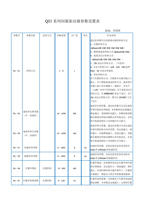
QS5系列伺服驱动器参数设置表
100
速度环比例常数的最小值。调整此值可以改变低速平稳性,不能太小,否则电机会爬行。
PA-37
速度环积分常数的变化率
0~100
10
速度环积分变化率。调整此值可以改变低速平稳性,不能太小,否则电机会爬行。
PA-38
电机与IPM模块对应的系数
1~5000
20B:601
30B:1202
电机与IPM模块对应的系数。
速度环积分常数,通过此参数可以设定速度环调节器的积分时间常数。设定值越大,刚性越大。负载惯量越大,此值应越大。请根据负载情况和驱动器默认参考值设定,在系统不振荡的情况下该参数应尽可能大。
PA-04
加速时间常数
6~1530
6
ms
加速时间常数,该设定值设定的是电机从0rpm到1000rpm的加速时间。
PA-05
QS5AA015M,QS5AA020M:PA38=3874/PA33
QS5AA030M:PA38=7748/PA33
QS5AA050M:PA38=10874/PA33
PA-39
低速时的电流环积分常数
1~5000
1
低速时的电流环积分常数,PA39=(1/10~1/3)PA30;(位置控制时,PA39=1)
PA-58
外部速度控制V8
-3000 - 3000
0
RPM
(ALR,CLE,INH)=(1,1,1)时的速度
PA-59
ALR定义选择
1/2
1
1:ALR为报警清除;2:ALR为速度选择;
PA-60
力矩增益
0:采用外部模拟量控制转矩输出;
非0值:输出转矩设定值(转矩大小不受外部模拟量控制)。
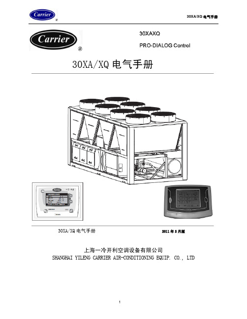
30XAXQ电器说明书(新版)
4.10.1 4.10.2 4.10.3 4.10.4 4.10.5 4.10.6 4.10.7 4.10.8 4.10.9
标准机组菜单................................................................................................................. 15 A 回路模拟值菜单 .......................................................................................................... 16 B 回路模拟值菜单 .......................................................................................................... 16 C 回路模拟值菜单 .......................................................................................................... 17 A 回路离散值菜单 .......................................................................................................... 17 B 回路离散值菜单 .......................................................................................................... 18 C 回路离散值菜单 .......................................................................................................... 18 设定点菜单..................................................................................................................... 19 输入菜单......................................................................................................................... 19
ARU52AX-L ARU75AX-L ARU90AX-L 系列吸油烟机用户手册说明书

USER MANUAL520, 750 & 900 // UNDERMOUNT HOOD ARU52AX-L | ARU75AX-L | ARU90AX-LIMPORTANT // Please ensure that you read through this user manual prior to installation and use. This manual contains important information to ensure optimal performance and keep you safe. Please retain your proof of purchase, as this will be required in the event that you require warranty service. Remember to retain this manual for future reference.520, 750 & 900 // UNDERMOUNT HOODHELLOCONGRATULATIONS ON THE SELECTION OF THIS SLIDEOUT RANGEHOOD. OUR APPLIANCES HAVE BEENSPECIFICALLY DESIGNED FOR AUSTRALIAN AND NEWZEALAND KITCHENS.Please read through this user manual carefully as it contains information that will ensure that your appliance is installed correctly, important operating & care instructions and also some advice of what you need to do if this appliance is not performing as intended.pg 2520, 750 & 900 // UNDERMOUNT HOODCONTENTSHELLO2 CONTENTS3 WARNING & SAFETY INFORMATION4 INSTALLATION & DUCTING5 OPERATING INSTRUCTIONS7 MAINTAINING YOUR RANGEHOOD8PROOF OF PURCHASE9NOTES10-11 CONTACT DETAILS12pg 3520, 750 & 900 // UNDERMOUNT HOODWARNING & SAFETY INFORMATIONThis appliance is not intended for use by persons (including children) with reduced physical, sensory or mental capabilities, or lack of experience and knowledge, unless they have been given supervision or instruction concerning use of the appliance by a person responsible for their safety. Young children should be supervised to ensure that they do not play with the appliance.There shall be adequate ventilation of the room when the rangehood is used at the same time as appliances burning gas or other fuels.You must read the details concerning the method and frequency of cleaning. There is a fire risk if cleaning is not carried out in accordance with the instructions.Do not flambé under the rangehood. Exhaust air must not be discharged into an existing flue which is used for exhausting fumes from appliances burning gas or other fuels.The minimum distance between the hob surface and the lowest part of the rangehood is 600mm. This distance shall be at least 650mm, if the rangehood is installed over a gas hob. If the instructions for the gas hob specify a greater distance, this has to be taken into account.Attention should be given to ensure that any applicable regulations concerning the discharge of exhaust air is fulfilled.If the supply cord of this equipment is damaged, it must only be replaced by the manufacturer or its service agent or a similarly qualified person in order to avoid a hazard.This appliance has been designed for indoor domestic use only.Do not remove or inspect the filters whilst the hood is in operation.520, 750 & 900 // UNDERMOUNT HOODpg 4DUCTINGpg 5IMPORTANT Before handling the rangehood during installation, it is recommended that you remove the filter to prevent damage.Fig 1.2 illustrates the minimum height from the hob surface to the underside of the rangehood.Electric hob - 600mm Gas hob - 650mmNOTICE: IF THE INTRUCTIONS FOR THE GAS HOB SPECIFY A GREATER DISTANCE, THIS HAS TO BE OBSERVED. ANY INSTALLATION ABOVE 750MM WILL COMPROMISE PERFORMANCE.483/710/859520/750/900300/500/65015010520, 750 & 900 // UNDERMOUNT HOOD *ARU52AX-L *314mm for bevelled edge panel *pg 6DUCTINGNOTICE // ALL DUCTING MATERIAL MUST BE COMPLIANT WITH THE LOCAL LAWS IN FORCE. INSTALLATION1. Remove the filter and light globes. (If installed)2. Remove the stainless steel fascia (4 screws) – take care not to damage the fascia.3. Determine the most efficient path for the ductwork, minimise bends and keep thelength of the ductwork to a minimum.4. It is important to run and finish (install roof / wall caps) prior to installation ofthe hood.5. Cut out the cabinetry as per the installation diagram. Ensure that access has beenallowed for the power cable.6. Hold the hood up to the underside of the cabinet (2 people required); Screw the hood to the cabinetry.7. Attach the ducting adaptor to the ducting.8. Re-install the stainless steel fascia.9. Re-install filter.10. Plug in the power to the unit, turn on and test.WARNING // Do not penetrate any screws into the rangehood as this may result in electrical hazards. Failure to install the screws or fixing device in accordance with these instructions may result in electrical hazards.RE-CIRCULATING (Carbon filter required)TOP DUCTING SIDE DUCTING DUCTED OPTION520, 750 & 900 // UNDERMOUNT HOODOPERATING INSTRUCTIONSFAN SPEEDOFF/LOW/MEDIUM/HIGH switch - located on the left hand side of the control panel.This unit features 3 speed settings; single line indicate low speed, double lines indicatethe medium speed & triple lines indicate high speed.To turn the unit off, set the speed switch to the 0 position (off).LIGHTOn/Off switch - located on the right hand side of the control panel as indicated in the diagram above.pg 7520, 750 & 900 // UNDERMOUNT HOODpg 8GENERAL MAINTENANCEEnsure that the power to the unit is switched off prior to cleaning the unit. Surface should only be cleaned with warm soapy water and a soft non-abrasive cloth. In coastal environments and humid areas more frequent cleaning is required to maintain the finish.FILTERSThese filters should be cleaned frequently, dependant on use (minimum monthly).Aluminium filers are dishwasher safe or can be cleaned with hot soapy water. Ensure that filters are thoroughly dry before re-installing. Slight discolouration may occur when cleaned in the dishwasher.LAMPSYour range hood is fitted with GU10 halogen or LED lamps depending on the model (refer to table below). Before replacing, ensure that lamps are completely cool and the power to the unit has been switched off. Replacement lamps can be purcahsed from your nearest hardware store.To remove the lamp, twist the lamp in an anti-clockwise direction.MODEL LAMP TYPE ARU52X and ARU75X 40W Halogen GU10 (X2)ARU52X-L and ARU75X-L 3W LED GU10 (X2)ARU52AX-L, ARU75AX-L & ARU90AX-L 3W LED GU10 (X2)MAINTAINING YOUR RANGEHOOD 520, 750 & 900 // UNDERMOUNT HOODV E R S I O N 5.0CONTACT DETAILSAUSTRALIA ARISIT PTY LIMITED 40-44 Mark Anthony Drive Dandenong South, VIC 3175 Australia Ph 1300 815 589FX (03) 9768 0838consumer.care@NEW ZEALAND ARISIT PTY LIMITED PO Box 68-140Newton, Auckland 1145New Zealand Ph (09) 306 1020FX (09) 302 0077sales@ARISTON IS COMMITTED TO ONGOING RESEARCH AND DEVELOPMENT. EVERY EFFORT HAS BEEN MADE TO ENSURE ALL INFORMATION IN THIS USER MANUAL IS CORRECT AT TIME OF GOING TO PRINT.DIMENSIONS SHOULD BE USED AS A REFERENCE ONLY AND ACTUAL DIMENSIONS SHOULD BE TAKEN FROM THE PHYSICAL PRODUCT ONLY.MANUFACTURER RESERVES THE RIGHT TO CHANGE SPECIFICATIONS WITHOUT NOTICE520, 750 & 900 // UNDERMOUNT HOOD。
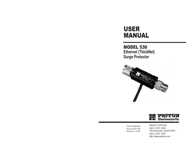
帕顿530以太网防雷器说明书.pdf
3
Using a hybrid circuit that incorporates Silicon Avalanche Diodes, the Model 530 can take repeated "hits" up to its rated capacity without degrading in performance. If the Model 530 should encounter a severe transient above its voltage rating, it will fail "open" to protect the connected hardware from damage. In this case, all signals (including data) are sent directly to ground, indicating to you that the Model 530 has "sacrificed itself" for your system and needs to be replaced.
• Operates at data rates to 10 Mbps
• Provides separate connection to chassis ground for surge handling
• Easy to install
DESCRIPTION
The Patton Model 530 thick Ethernet surge protector guards N-type Ethernet ports and connected equipment against data loss and hardware damage due to transient surges. Providing 1.8 Kilowatts of clamping transient protection, the Model 530 is easy to install and won't slow network performance.
开利 A Q运行维护手册
30XA/XQ 螺杆式风冷冷水(热泵)机组制冷量:317~1551kW制热量:317~1268kW开机运行维护手册2007年5月版上海一冷开利空调设备有限公司SHANGHAI YILENG CARRIER AIR-CONDITIONING EQUIPMENT CO., LTD30XA/XQ开机运行维护手册目录1. 介绍................................................................................................... (4)安装安全要求.............................................................................................. (4)压力设备和部件.............................................................................................. (5)维护安全事项.............................................................................................. (5)维修安全措施.............................................................................................. (6)2.进场检验................................................................................................... (8)设备进场的检验.............................................................................................. (8)机组的搬运和就位.............................................................................................. (8)机组的搬运.......................................................................................... (8)机组的就位.......................................................................................... (8)3. 外形尺寸,安装间距................................................................................................... (10)30XA............................................................................................ (10)30XA452G ....................................................................................... (10)30XA502G ....................................................................................... (11)30XA602G-702G .................................................................................. (12)30XA852G ....................................................................................... (13)30XA1002G ...................................................................................... (14)30XA1202G-1352G ................................................................................ (15)30XA1502G模块1 .......................................................................................... (16)30XA1502G模块2 .......................................................................................... (17)30XQ............................................................................................ (18)30XQ320 .................................................................................... (18)30XQ640 .................................................................................... (19)30XQ960 .................................................................................... (20)30XQ1280 ................................................................................... (21)多台机组安装间距.............................................................................................. (21)4. 30XA/XQ 机组技术和电气参数 (22)30XA/XQ技术参数——标准机组*** (22)30XA....................................................................................... (22)30XQ....................................................................................... (23)30XA技术参数——PT018选项*** (24)30XA/XQ电气数据——标准机组 (25)30XA....................................................................................... (25)30XQ....................................................................................... (25)30XA电气——PT018 ...................................................................................... (26)压缩机电气数据.............................................................................................. (27)每个回路使用的压缩机(A,B,C,D) (27)30XA....................................................................................... (27)30XQ....................................................................................... (27)电气数据,水力模块选项 ..............................................................................................285. 电气连接................................................................................................... .. (29)电源.............................................................................................. (29)130XA/XQ开机运行维护手册电压不平衡率(%)的计算 (29)电源连接/断开开关.............................................................................................. (29)推荐连线部分.............................................................................................. (30)30XA/XQ机组连线的最大和最小截面尺寸 (31)30XA....................................................................................... (31)30XQ....................................................................................... (31)接入电线.............................................................................................. (32)现场控制连线.............................................................................................. (32)6. 运用数据................................................................................................... .. (33)机组运行范围.............................................................................................. (33)30XA....................................................................................... (33)30XQ....................................................................................... (34)最小水流量(机组不带水力模块) (35)最大水流量(机组不带水力模块) (36)蒸发器变流量.............................................................................................. (36)系统最小水容量.............................................................................................. (36)系统最大水容量.............................................................................................. (37)蒸发器水流量.............................................................................................. (37)蒸发器压降曲线.............................................................................................. (38)30XA....................................................................................... (38)30XQ....................................................................................... (38)7. 水管连接................................................................................................... .. (38)管路操作注意事项.............................................................................................. (39)水管连接.............................................................................................. (40)流量控制.............................................................................................. (42)换热器水室的拆卸.............................................................................................. (42)防冻保护.............................................................................................. (43)30XA....................................................................................... (43)标准机组...................................................................................... (43)蒸发器防冻保护 ..................................................................................... (43)30XQ....................................................................................... (43)双机组主从方式运行.............................................................................................. (43)水泵压力和流量曲线(只适用于 30XA单冷机组) (44)可用系统静压(只适用于 30XA单冷机组) (45)8. 系统主要部件和运行数据................................................................................................... . (47)带有滑阀的双转子螺杆压缩机 (47)油过滤器.......................................................................................... (47)制冷剂.......................................................................................... (47)润滑油.......................................................................................... (47)供油电磁阀.......................................................................................... (47)吸气及经济器回气滤网 (47)冷量控制系统.......................................................................................... (47)压力容器.............................................................................................. . (47)管壳式换热器.......................................................................................... (48)230XA/XQ开机运行维护手册油分离器.......................................................................................... (48)经济器.......................................................................................... (49)储液器(只适用于30XQ) (4)9气液分离器(只适用于30XQ) (49)高压开关.............................................................................................. (49)四通换向阀.............................................................................................. (49)冷凝器.............................................................................................. (49)风机.............................................................................................. (50)电子膨胀阀(EXV)......................................................................................... (50)湿度指示器.............................................................................................. (50)干燥过滤器.............................................................................................. (50)传感器.............................................................................................. (50)9.选项和附件(只适用于30XA 单冷机组) (52)10. 标准维护................................................................................................... (53)维护A............................................................................................... (53)维护B .............................................................................................. (53)维修C .............................................................................................. (54)主要电气连接处的紧固.............................................................................................. (54)主要螺栓和螺母的紧固................................................................................................55冷凝器盘管.............................................................................................. (55)蒸发器维护.............................................................................................. (56)压缩机维护.............................................................................................. (56)油分离器.......................................................................................... (56)油过滤器的更换 ......................................................................................... (56)压缩机转向控制 ......................................................................................... (57)热泵常见故障及排除方法 (5)711. 30XA/XQ 冷水(热泵)机组开机预检(安装人员预检后需要填写的表格) (59)本公司保留对此说明书有关内容进行修改而不预先通知用户的权利330XA/XQ开机运行维护手册1. 介绍30XA/XQ 雷霆系列螺杆式风冷冷水(热泵)机组专为工业、建筑空调用途设计。
Q开关电源使用说明书

声光Q开关电源使用说明书(适用于QSD5027、QSD7527)桂林市飞鹰激光应用技术有限公司欢迎您使用我公司生产的QSD系列Q开关电源。
在使用QSD系列Q开关电源之前,请您务必仔细阅读本使用手册。
本手册适用于QSD系列标准产品。
对于用户有特殊要求的特制产品,请仔细阅读手册中另附的特别说明。
请您打开包装箱,核对随机附件。
电源线一根15芯计算机针式插头一只Q9插头一套目录一、简介 11.概述................... 错误!未定义书签。
2.型号说明............... 错误!未定义书签。
3.主要性能和技术指标..... 错误!未定义书签。
二、工作原理及结构. . . . . . . . . . . . . . . . . . . . . . . . . . . . . . . .. 31.Q开关元件结构及工作原理错误!未定义书签。
1.1.结构 .............. 错误!未定义书签。
1.2.Q开关关断激光原理.. 错误!未定义书签。
1.3. Q开关进行Q调制..... 错误!未定义书签。
1.4.Q开关的等效阻抗... 错误!未定义书签。
2.Q电源结构与原理........ 错误!未定义书签。
2.1.开关电源及射频功率的调节. 错误!未定义书签。
2.2.射频单元.......... 错误!未定义书签。
2.3.主控单元 (8)2.3.1.控制电源 (8)2.3.2.控制方式 (8)2.3.3.调制脉冲及出光控制有效电平的设置122. 3. 4. 保护逻辑 (12)2.3.4.1.超温保护 (12)2.3.4.2.外控保护 (12)2.3.4.3.反射保护 (13)2.4.对外接口 (13)2.5.控制面板........... 错误!未定义书签。
2.5.1.数显表……………………………… ..17 2.5.2.RUN/STOP指示灯 (17)2.5.3.ALARM(报警)指示灯 (18)2.5.4.TEST(测试)指示灯 (18)2.5.5.M1、M2、M3 指示灯 (18)2.5.6.按键说明 (18)2.5.7.电源开关 (20)三、电源与Q开关元件的阻抗匹配 20四、安装及操作说明 211.安装条件 (21)2.电气安装连线 (21)3.操作流程说明 (23)五、异常现象释疑…………………………………………. .. 23附图 (26)一、简介1.概述QSD系列Q开关电源是针对不同的应用领域精心设计的高品质的声光Q开关(Acousto-Otipc Q-switch)驱动电源。
QS5按键说明及调试方法

按键名称:“MODE”模式键“DEC”减小键“INC”增加键“ENTER”确认键设置参数操作上电后按“ENTER”显示PA-SET(参数设置)→按“ENTER”显示PA-1(参数号)→按“DEC”键或“INC”键选择参数号→按“ENTER”显示参数值→按“DEC”键或“INC”键增加或减小参数值(更改参数,数值闪烁)→按“ENTER”确认更改(数值不再闪烁)→按“MODE”退回上一级显示(一直退到PA-SET画后)→按“DEC”键或“INC”键(切换显示画面一直切换到EE-SET参数管理画面)→按“ENTER”显示EE-rt (参数保存)→按“ENTER”显示EE-NO→按“DEC”键或“INC”键切换至EE-YES(显示闪烁)→按“ENTER”确认保存(显示FINISH保存完成)具体操作请参看说明书调试方法1:第一步必须在电机线未接的情况下,设置好PA35参数,使伺服驱动器与伺服电机相匹配。
(PA35=3:ACH,四对极2500线电机。
PA35=5-14:ACS,两对极2500线电机。
PA35=17:ACM,四对极2500线电机)2:按照配套电机的额定电流值修改PA33参数以及PA38的值。
此参数会影响过流保护值和过载保护值。
3:检查电流环比例常数;PA-29和电流环积分常数PA-30(出厂时已设好,一般不需改)4:根据实际的传动比设置PA18、PA19电子齿轮比。
建议用户把电子齿轮比设置到交流伺服驱动器中,不要放到上位机。
5:刚性调整:为提高系统刚性减小振动,先将PA-22设为0关闭位置反馈低通滤波器,同时将PA6设置到经验值的最小值。
(推荐低刚性10~30、中刚性30~60、高刚性60~100)一般情况下,只需调整PA2、PA36、PA32和PA29这几个比例常数。
PA3、PA37、PA40和PA30这几个积分常数一般不需调整。
刚性调整一般分为以下三步:①第一步先将PA-32调至0,让电机工作在每分钟几转内,加大PA36,用千分表或百分表测试工作台的移动是否均匀或用手感觉电机运动是否平稳。
QS5AA030M说明书
目录
使用前的注意事项 .............................................................................................. 1 第一章 .................................................................................................................. 5 产品的确认及各部分的名称.............................................................................. 5
第六章............................................................................................... 61
错误报警及处理 ................................................................................................ 61 6.1 报警一览表 .............................................................................................. 61 6.2 报警处理方法 .......................................................................................... 62
第二章.................................................................................................9
超级A品牌净化器产品说明书
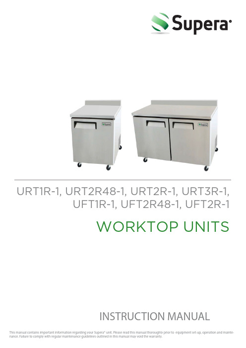
URT1R-1, URT2R48-1, URT2R-1, URT3R-1,UFT1R-1, UFT2R48-1, UFT2R-1WORKTOP UNITSINSTRUCTION MANUALI N S T R U C T I O N M A N U A L Please read the manual carefully and follow allinstructions. Failure to do so may void your warranty.The manufacturer cannot be held liable in the following cases:•Improper installation and servicing •Misuse of the refrigerator •Improper or inad equate maintenance •Unauthorized modification or tampering •Use of non-original spare parts •Partial or total failure to comply with the instructionsTRANSPORTATION Unit may not be placed on its sid e for any reason during shipping. It should be stored in a protected and covered environment at a temperature between -25°C and 55°C with an ambient humidity of 30% to 90%. Do not stack more than 4 units high.INSTALLATION AND SET UPUNIT MUST RUN FOR 24 HOURS BEFORE USING!•The unit is wrapped in absorbent material inside a cardboard box and strapped on a wood pallet. Remove all straps and packaging, including the PVC protective film. If damage is noted, file a claim immediately.•Install the units on a level surface. If the surface is not level,the legs can be adjusted.•Make sure that it is not placed in direct sunlight or by a heat source.•There should be 5cm clearance from wall and unit so that there is proper air circulation for the condensing unit.•Before use, the interior and exterior should be cleanedwith a soft cloth.•Do not use an abrasive cleaner or scour pad!I N S T R U C T I O N M A N U A LCONNECTING TO THE MAIN POWER SUPPLY•Before plugging in, make sure that the main power source is ground ed properly and matches the voltage rating of that of the unit (found on the rating label).•Do not in any way remove the ground prong.•Always make sure that the power cord is in goodcondition, is not frayed and does not show abrasion.•Do not use an extension cords or adapter plugs and only plug in one unit per circuit.•When plugging and unplugging, do so by gripping onto the plug.•Plug in the unit and adjust the thermostat to your desired temperature.MAINTENANCE AND CLEANINGRegular cleaning of the unit is strongly recommended eachmonth. •Before cleaning, power off and unplug the unit.•Clean the exterior and interior with a mild detergent and soft cloth. Do not use abrasive detergents and cloths!Cleaning the Condenser•The condenser should be thoroughly cleaned every 4months or when the fins get dirty. It can be cleaned with a dry brush or a vacuum cleaner.I N S T R U C T I O N M A N U ALTROUBLESHOOTINGPower supply failure•Check that the plug is plugged in correctly•Make sure that the switch is on•Check the main power sourceRequired temperature is not achieved•Check that the thermostat range is correctly regulated•Check that the condenser is not blocked with dust.Improper air flow will affect unit to function at its optimallevel•Unit should not be over-stuffed, and not load ed with hot food•Make sure that the unit is not close to a heat sourceCabinet is leaking water•The drip tray may be missing or damaged•Make sure the pipes are not obstructed•The unit may not be levelCabinet is noisy•The unit may not be level•The frame may have loose screws or boltsIf problems persist after following the troubleshooting guide, please contact your local dealer and have ready your model number, serial number, and date of purchase. You may be asked to also provid e proof of sales. Unnecessary service will be billed to the customer.Please make sure to go over this troubleshooting guidebefore calling for service.I N S T R U C T I O N M A N U ALProper disposal is the responsibility of the owner, and these instructions should be followed to prevent injuries and child entrapment. •Remove all doors and shelves so that a child cannot get trapped inside.•Follow the guidelines of the city garbage disposal program.•The refrigerant will need to be removed by a qualified service technician.CIRCUIT DIAGRAMPROPER DISPOSALI N S T R U C T I O N M A N U ALTechnical ParametersI N S T R U C T I O N M A N U ALOfficial Approvals-Conforms to UL STD. 471-Conforms to NSF 7-Certified to CSA STD. C22.2 NO.12O © SUPERA, 2014Version 5 | May 2014 LIMITED WARRANTYSUPERA REFRIGERATION EQUIPMENT MODELS:Reach-In Refrigerators & Freezers [R1R-1, R2R-1, R3R-1, F1R-1, F2R-1, F3R-1]Undercounter Refrigerators & Freezers [UR1R-1, UR2R-1, UR2R6-1, UF1R-1, UF2R-1, UF2R6-1]Sandwich/Salad Prep Tables, Mega-Top Prep Tables & Pizza Prep Tables [SSPT1R, SSPT2R-1, SSPT2R6-1, MTPT1R-1, MTPT2R-1, MTPT2R6-1, PPT1R-1, PPT2R-1, PPT3R-1]Glass Door Merchandisers [G1M-23-B-1, G1M-23-W-1, G2M-SW-48-B-1, G2M-SW-48-W-1, G3M-70-B-1, G3M-70-W-1]Claims:All claims for parts or labor must be made directly through SUPERA, LLC. All claims should include: model number of the unit, the serial number of the cabinet, proof of purchase, date of installation, and all pertinent information supporting the alleged defect. In case of compressor replacement under warranty, either compressor or compressor tag must be returned to SUPERA, LLC along with above listed information. Failure to comply with warranty policies will result in voiding claims. Any service provided without authorization from Supera, LLC will not be covered by Supera, LLC.Two-Year Parts & Labor Warranty: SUPERA, LLC warrants all new refrigerated components, the cabinet and all parts, to be free from defects in materials or workmanship, under normal and proper use and maintenance service as specified by SUPERA, LLC and upon proper installation (indoor building only) and start-up in accordance with the instruction packet supplied with each SUPERA, LLC unit. SUPERA, LLCʼs obligation under this warranty is limited to a period of two (2) years from the date of original purchase.Any part, covered under this warranty that is determined by SUPERA, LLC to have been defective within two (2) years of original installation date is limited to the repair or replacement, including labor charges, of defective parts or assemblies. The labor warranty shall include ONLY pre-authorized time and up to sixty miles of travel for the service company.Additional Three-Year Compressor Warranty: In addition to the two (2) year warranty stated above, SUPERA, LLC warrants its hermetically sealed compressor to be free from defects in both material and workmanship under normal and proper use and maintenance service for a period of three (3) additional years from the date of original installation, but not to exceed five (5) years and three (3) months after purchase.Compressor determined by SUPERA, LLC to have been defective within this extended period will, at SUPERA, LLCʼs discretion, be either repaired or replaced with a compressor or compressor parts of similar design and capacity.The three (3) year extended compressor warranty applies only to hermetically sealed parts of the compressor and does not apply to any other parts or components, including, but not limited to, cabinet, paint finish, temperature control, refrigerant, metering device, driers, motor starting equipment, fan assembly or and other electrical components, etcetera.Compressor Warranty: The five-year compressor warranty detailed above will be void if the following procedure is not carefully adhered to:1.This system contains R404A or R134a refrigerant and Polyol Ester lubricant. The Polyol Ester lubricant has rapid moisture absorbingqualities.2.Drier replacement is very important and must be changed when a system is opened for servicing. A620 copper drier or better is highlyrecommended.3.Micron level vacuums must be achieved to insure low moisture levels in the system. 500 microns or lower must be obtained.4.When compressor is grounded, suction drier and 620 drier or better must be replaced.pressor must be obtained through SUPERA, LLC, unless otherwise specified in writing, through SUPERA, LLCʼs warranty department. Not Covered Under This Warranty: SUPERA, LLCʼs sole obligation under this warranty is limited to either repair or replacement of parts, subject to the additional limitations below. This warranty neither assumes nor authorizes any person to assume obligations other than those expressly covered by this warranty.Warranty does not cover service requests for free replacement and/or recall parts.SUPERA, LLC HAS FINAL DESCRETION ON ALL WARRANTY REQUESTS.NO CONSEQUENTIAL DAMAGES. SUPERA, LLC IS NOT RESPONSIBLE FOR ECONOMIC LOSS; PROFIT LOSS; OR SPECIAL, INDIRECT, OR CONSEQUENTIAL DAMAGES, INCLUDING WITHOUT LIMITATION, LOSSES, SERVICE TECHNICAN ERRORS, OR DAMAGES ARISING FROM FOOD OR PRODUCT SPOILAGE REGARDLESS OF WHETHER OR NOT THEY RESULT FROM REFRIGERATION FAILURE. WARRANTY IS NOT TRANSFERABLE, This warranty is not assignable and applies only in favor of the original purchaser/user to whom delivered. ANY SUCH ASSIGNMENT OR TRANSFER SHALL VOID THE WARRANNTIES HEREIN AND SHALL VOID ALL WARRANTIES, EXPRESS OR IMPLIED, INCLUDING ANY WARRANTY OF MERCHANTABILITY OR LABOR COVERAGE FOR COMPONENT FAILURE OR OTHER THE WARRANTY PACKET PROVIDED WITH THE UNIT. ALTERATION, NEGLECT, ABUSE, MISUSE, ACCIDENT, DAMAGE DURING TRANSIT OR INSTALLATION, FIRE, FOOD, ACTS OF GOD. SUPERA, LLC is not responsible for the repair or replacement of any parts that SUPERA, LLC determines have been subjected after the date of manufacture to alteration, neglect, abuse, misuse, accident, damage during transit or installation, fire, flood, or act of GOD. IMPROPER ELECTRICAL CONNECTIONS. SUPERA, LLC IS NOT RESPONSIBLE FOR THE REPAIR OR REPLACEMENT OF FAILED OR DAMAGED COMPONENTS RESULTING FROM ELECTRICAL POWER FAILURE, THE USE OF EXTENSION CORDS, LOW VOLTAGE, OR VOLTAGE DROPS TO THE UNIT. NO IMPLIED WARRANTY OF MERCHANTABILITY OR FITNESS FOR A PARTICULAR PURPOSE; THERE ARE NO OTHER WARRANTIES, EXPRESSED, IMPLIED OR STATUTORY, EXCEPT THE TWO (2) YEAR PARTS & LABOR WARRANTY AND THE ADDITIONAL THREE (3) YEAR COMPRESSOR WARRANTY AS DESCRIBED ABOVE. THESE WARRANTIES ARE EXCLUSIVE AND IN LIEU OF ALL OTHER WARRANTIES, INCLUDING IMPLIED WARRANTY AND MERCHANTABILITY OR FITNESS FOR A PARTICULAR PURPOSE. THERE ARE NO WARRANTIES, WHICH EXTEND BEYOND THE DESCRIPTION ON THE FACE HEREOF. Outside U.S. and Canada; This warranty does not apply, and SUPERA, LLC is not responsible for, any warranty claims made on products sold or used outside the continent of the United States and Canada. Installation in a residential application will void all warranties.Supera Customer Care Toll-Free Service Line:1-866-953-3288For additional product and warranty information, please visit our website at:。
五星级远程加强器安装说明书
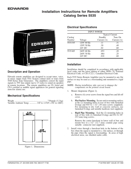
P-047550-0857 ISSUE 3 © 1998FARMINGTON, CT 203-699-3000 FAX 860-677-7746Installation Instructions for Remote AmplifiersCatalog Series 5535EDW ARDSInstallationInstallation should be completed in accordance with applicable local codes and the latest edition of either NFPA 70, National Electrical Code, or CSA C22.1, Canadian Electrical Code.Each 5535 Series Remote Amplifier may be mounted to any flat surface or may be used as a freestanding unit mounted to a rigid pipe.NOTE:During installation, take care not to damage thecomponents on the printed circuit board.1.Mount Adaptatone (Figure 2).a.Remove (4) cover screws from the signal box and lift off cover.b.Flat Surface Mounting . Secure unit to mounting surface at the (2) mounting holes in rear of box with furnished O-rings and #10 X 1 1/2" (38 mm) screws (supplied).For mounting to dry wall or concrete surfaces, use furnished O-rings and suitable hardware (not supplied).c.Rigid Pipe Mounting . Seal the (2) mounting holes in rear of box with (2) furnished O-rings and #12 X 3/8"(9.5 mm) long screws.Remove the center knockout in lower wall of box and mount box to a 1/2" (12.7 mm) conduit pipe using suitable connector (not supplied).2.Install wires through a knockout hole in the bottom of the box when the signal is mounted to a flat surface, or through the pipe when the signal is freestanding. In areas of high electrical noise, use shielded audio cable.Description and OperationEdwards remote amplifiers are designed to accept tones, voice,or music inputs from 5541 System control units or tones from 5540 Series Tone Generators. The amplifiers convert the input signals to 70V line output (up to 15 watts) to sound on speakers in remote locations. The remote amplifiers are UL listed and CSA certified as audible signal appliances for general signaling (non-fire alarm) use.Mechanical SpecificationsWeight .............................................................7 Pounds (3.2 kg)V ariable Ambient Temp.............-31F to +151F (-35C to +66C)Electrical SpecificationsFigure 1. DimensionsINPUT POWERTypical Current Catalog Standby Tone On Number V oltageCurrent (A)Current (A)5535-N5120V 60 Hz .11.31120V 50 Hz .30.4024V DC .02.605535-R5240V 60 Hz .053.20240V 50 Hz .064.2524V DC.018.603.Wire Adaptatone as follows:a.Connecting 5535 Amplifier(s) to 5541 System ControlUnits (Figure 3).Connect the wires from the 5541 System Control unitTB2-Audio Out, L and H terminals to the 5535 RemoteAmplifier TB2-L and H terminals. Observe polarity. Forother system connections, see instructions P-047550-0858 shipped with the 5541 System Control Units.b.Connecting 5535 Amplifier(s) to 5541B SystemControl Units (Figure 3).Connect the wires from the 5541B System Control unitTB2 Area 1 Audio Out terminals to the 5535 RemoteAmplifier TB2-L and H terminals. Observe polarity. Forother system connections, see instructions P-047550-1558 shipped with the 5541B System Control Units.c.Connecting 5535 Remote Amplifier(s) to a Series 5540or 5540A Central Tone Generator (Figure 4).Connect the wires from the Central Tone Generator TB2-HI and LO terminals to the 5535 Remote Amplifier TB2-H and L terminals. Observe polarity. For other systemconnections, see instructions P-047550-0179 shippedwith 5540 Series Central Tone Generators or P-047550-0228 shipped with 5540A Series Central ToneGenerators.d.Connecting 5535 Remote Amplifier(s) to a Series5540B Central Tone Generator (Figure 4).Connect the wires from the Central Tone Generator TS1-9 and 10 Tone Out terminals to the 5535 RemoteAmplifier TB2-H and L terminals. Observe polarity. Forother system connections, see instructions P-047550-1550 shipped with 5540B Series Central Tone Generators.e.Speaker Connections (Figure 3 or 4). The RemoteAmplifier provides up to 15 watts audio power to 70Vline speakers. For best service use the Edwards 5547and/or 5551B Series Speakers.Connect the speakers to the two yellow wires comingfrom the transformer that is mounted on the RemoteAmplifier's printed circuit board.f.Power Supply Connections (Figure 3 or 4).g.Standby Power (Optional) (Figure 3).A 2.5 to 3 ampere hour 24V DC battery is recommendedfor standby power. This type of battery provides 24 hoursof standby service.Connect standby power to 5535 TB1-B(+) andTB1-B(-) terminals. Observe polarity.4.Adjust volume level, if desired, by turning potentiometer(Figure 3 or 4).5.Replace the signal box cover.6.V erify operability as follows.a.Initiate a signal and verify that is sounds on all thespeakers connected to the Remote Amplifier. Resetinitiating device.b.If standby power is used, verify that it will functionproperly. Remove the 120V AC or 240V AC power,initiate a signal and verify that is sounds on all speakersthat are connected to a Remote Amplifier. Reset theinitiating device and restore 120V AC or 240V AC power.Maintenance and TestFigure 2. Remote Amplifier Mounting.Connect the AC power source wires to the two black pigtailed wires coming from the transformer on the inside cover of the remote amplifier.Examine the unit semi-annually for accumulation of dirt. Clean if necessary.The Remote Amplifier should be tested annually or as required by the authority having jurisdiction to ensure continuous service.P-047550-0857 ISSUE 3Figure 3. Remote Amplifier Wiring to System Control Unit (5541B Series Shown)Figure 4. Remote Amplifier Wiring to Central ToneGenerator (5540B Series Shown)P-047550-0857 ISSUE 3。
芯达特技术有限公司产品介绍-5AP电动机保护器说明书

| 5APMOTOR PROTECTOR As a world leader in automotive motor protection, Sensata Technologies has developed the smallest bimetal based protection available at the market today, the 5AP . The 5AP is developed to operate in wide temperature and current ranges, while providing consistent performance characteristics and excellent reliability. CAD-based design techniques combined with 6-Sigma supported manufacturing lines and the best quality control systems give this product maximum safety and reliability. The 5AP operates as a sensi- tive power cut-out which is widely used in Window-Lifts, Adjuster-Motors, Door- Locks and various other applications. One protector series covers a broad range of applications, thus providing the flexibility to customize a particular rating based on the specific requirements of universal applications. But let’s find out what really makes the 5AP perform its job as it does: the Sensata Klixon ® control.The Klixon ® disc is made of a combination of different metals with a predetermined calibration point. When heated, one of the metals expands more than the other, causing the disc to snap. As a world leader in bimetal technology and bimetal-based devices, Sensata Technologies has set its goals of constant improvement and maximum reliability during years of operation and thousands of cycles.The 5AP is manufactured on fully automatic equipment, custom designed to meet the various requirements of today’s automotive industry. As a world leader in automotive motor protection, Sensata Technologies has developed the smallest bimetal based protection available at the market today, the 5AP . The 5AP is developed to operate in wide temperature and current ranges, while providing consistent performance characteristics and excellent reliability. CAD-based design techniques combined with 6-Sigma supported manufacturing lines and the best quality control systems give this product maximum safety and reliability. The 5AP operates as a sensitive power cut-out which is widely used in Window-Lifts, Adjuster-Motors, Door-Locks and various other applications. One protector series covers a broad range of applications, thus providing the flexibility to customize a particular rating based on the specific requirements of universal applications.Klixon ® snap-action controlsDesign and operating principlesIntroductionKey Benefits• Thermal motor protection reacting to both current and temperature • Wide variety of standard thermal configurations • Terminal materal provides trouble-free welding• Eligible for customer partnumber printed on product as well as col-or-coding• Varying of both bimetal and S-wire resistivity creates a current-time characteristic optimized for each specific application• Unique combination of bimetal disc and resistivity wire guarantees very precise tripping times thus prevents too high motor temperature • Protector selection and application testing by Sensata Technologieslaboratory with results in extended report at your serviceSPECIFICATIONSSTANDARD TERMINAL CONFIGURATIONS7.917.7 4.72.8667.923.7(Include cut -off tab)3.252.90.250.3563.253.252.8AAAJ JJNNNR RR617.7(Include cut -off tab)3.257.92.90.250.35445.923.763.2563.257.9Just provide us with your specifications concerning specific current and temperaturerise conditions and we will select a matching 5AP motor protector and provide you with samples. But we do more than that. A skilled staff is available to perform application testing and protector selection in a well equipped laboratory with sophisticated, state-of-the-art equipment, located at each region. In close cooperation with the customer we develop the optimum solution, providing the lowest cost of ownership and thus increasing your competitive advantage. If motor testing and assembly are required on a larger scale, pilot series for your verification will be supplied within a very short cycle time. With design cycles becoming shorter and shorter, you can expect our prompt reply. If you wish to select your own ratings we have a software tool available to assist you in making the right selection.5AP production facility is located in Asia.Serving the customerPage 3Americas+1 508 236 2551electrical-protection-sales@Europe, Middle East & Africa +3 174 357 8156*********************.com Asia Pacific***************************.comChina +86 (21)2306 1651India +91 (40)4033 9611Japan +81 (45)277 7104Korea +82 (53) 644 9685CONTACT USSensata Technologies, Inc. (“Sensata”) data sheets are solely intended to assist designers (“Buyers”) who are developing systems that incorporate Sensata products (also referred to herein as “components”). Buyer understands and agrees that Buyer remains responsible for using its independent analysis, evaluation and judgment in designing Buyer’s systems and products. Sensata data sheets have been created using standard laboratory conditions and engineering practices. Sensata has not conducted any testing other than that specifically described in the published documentation for a particular data sheet. Sensata may make corrections, enhancements, improvements and other changes to its data sheets or components without notice.Buyers are authorized to use Sensata data sheets with the Sensata component(s) identified in each particular data sheet. HOWEVER, NO OTHER LICENSE, EXPRESS OR IMPLIED, BY ESTOPPEL OR OTHERWISE TO ANY OTHER SENSATA INTELLECTUAL PROPERTY RIGHT, AND NO LICENSE TO ANY THIRD PARTY TECHNOLOGY OR INTELLECTUAL PROPERTY RIGHT, IS GRANTED HEREIN. SENSATA DATA SHEETS ARE PROVIDED “AS IS”. SENSATA MAKES NO WARRANTIES OR REPRESENTATIONS WITH REGARD TO THE DATA SHEETS OR USE OF THE DATA SHEETS, EXPRESS, IMPLIED OR STATUTORY, INCLUDING ACCURACY OR COMPLETENESS. SENSATA DISCLAIMS ANY WARRANTY OF TITLE AND ANY IMPLIED WARRANTIES OF MERCHANTABILITY, FITNESS FOR A PARTICULAR PURPOSE, QUIET ENJOYMENT, QUIET POSSESSION, AND NON-INFRINGEMENT OF ANY THIRD PARTY INTELLECTUAL PROPERTY RIGHTS WITH REGARD TO SENSATA DATA SHEETS OR USE THEREOF.All products are sold subject to Sensata’s terms and conditions of sale supplied at SENSATA ASSUMES NO LIABILITY FOR APPLICATIONS ASSISTANCE OR THE DESIGN OF BUYERS’ PRODUCTS. BUYER ACKNOWLEDGES AND AGREES THAT IT IS SOLELY RESPONSIBLE FOR COMPLIANCE WITH ALL LEGAL, REGULATORY AND SAFETY-RELATED REQUIREMENTS CONCERNING ITS PRODUCTS, CURVESThe curves of First Cycle Tripping time and Ultimate trip current are meant to be for selecting samples to perform verification tests only. In the figures two curves of a wide range of possibilities are shown. The level and slope can be varied by making an other selection for the pre-set temperature, bimetal discand/or heater.WARNINGSRISK OF MATERIAL DAMAGE AND HOT ENCLOSURE• The product’s side panels may be hot, allow the product to cool before touching • Follow proper mounting instructions including torque values • Do not allow liquids or foreign objects to enter this productFailure to follow these instructions can result in serious injury, or equipment damage.HAZARD OF ELECTRIC SHOCK, EXPLOSION OR ARC FLASH• Disconnect all power before installing or working with this equipment • Verify all connections and replace all covers before turning on powerFailure to follow these instructions will result in death or serious injury.。
QWA-5 使用手册(1)

使用手册石英钟表测试仪QUARTZ WATCH/CLOCK ANALYZERQWA-5广州可瑞电子科技有限公司注意:仪器一定要保持电源接地良好,及插座的地线端一定要接地,才能保证仪器的灵敏度。
如果采用恒温晶振作为频标,开机需预热10 分钟以上,所测量值才为准确测量值。
警告:感应测试座与主机的连接头请勿在主机通电情况下拔插,否则会损坏主机及感应测试座。
第一章概论QWA-5是一款目前应用于钟表与计时器界最广、功能最强的利器。
它提供了最快速简便而且精确的石英钟表测试方式,使您能节省大量的测试和检修的时间。
QW A-5运用的范围非常的广泛,例如用作石英晶体、指针式石英钟表、数字式石英钟表等的准确度测试;此外,它还可以测量马达线圈,灯阻,消耗电流与消耗功率,以及检测钟表内IC等等,并内附有可调电源0---6V,这些可使您检修测试及生产时非常方便,只要您能妥善运用,您会发觉它的确是目前世界上最先进、最实用的石英钟表检测仪器。
主要性能指标:时间参数测量的准确度为±0.5 PPM选配恒温晶振可以达到±0.05PPM第二章如何安装QWA-5第一部分:打开包装当您打开QW A-5包装时,请检查下列各项:1.主机1台2.附机(感应器)1台3.操作手册1本4.电源线1条5.感应测试笔1条6.合格证卡1张以上各项,如有缺失,请立即与销售人员以及经销商联络补足。
第二部分:面板说明(如图2-1)1.感应区2.石英晶体插座3.测指针式手表开关位置4.信号强度指示表5.测数字式手表开关位置6.附机电源指示灯7.主机电源开关及指示灯8.信号指示灯9.速度指示灯10.负极性指示灯11.正极性指示灯12.主输出数字显示13.电压测量按键14.电阻测量按键15.电流测量按键16.良品或非良品指示灯17.可变电压源按键18.秒/月测量键19.秒/日测量键20.PPM测量键被测物(表,钟,计时器)所放置位置。
测频率32768HZ的钟表用石英晶体时,将石英晶体插入此插座。
活化仪电子版说明书

活化仪电子版说明书作者: 日期:RN-XF蓄电池智能活化仪使用说明书陕西瑞能电气有限责任公司15第一部分 仪器使用说明书••… I 第' 一^章 彳概^述 ............1.1产品概述 ............... 1.2主要功能 ............... 1.3技术指标 ...............第二章主要部件及接线说明2.1主要部件 ............... 2.2接口说明及连线 .........第三章操作指南 ..............开机 .................. 电池充放电 ............ 内阻测试 ............... 电池活化 ...............数据操作 ............... 系统设置 .............. 3.1 3.2 3.3 3.4 3.5 3.6 第四章常见问题及解决…•… 第二部分软件使用说明书••…1打开软件 ................. 2功能操作 ................. 电池充电操作 ....... 电池放电操作 ....... 内阻测试操作 ........电池活化操作 ........ 数据处理操作 ........2.1 2.2 2.3 2.4 2.510 12 13 14 14 15 15 16 17 18第一部分仪器使用说明书第一章概述1.1、产品简介RN-XF蓄电池智能活化仪(2V/12V 一体机是陕西瑞能电气有限责任公司专利产品,适用于2V、12V蓄电池,以下简称活化仪),是日常维护中专用于对落后蓄电池处理的便携式产品。
活化仪采用最先进的脉冲活化技术,针对不同落后电池的实际情况,设置多个循环周期对落后电池做多次循环充放电活化,彻底“清洗”极板硫化物质,有效激活电池硫化的活性物质,从而使电池得到活化,容量得到提升。
1.2、产品主要功能及特点1.2.1、主要特点1、活化仪具有单节电池旁路技术,实现单节电池在线活化,方便、实用。
5KVA全自动变压器控制箱说明书

●暂停功能,自动控制时,此功能可做到在任意点实现升压或降压的暂停,暂停时间可由试验人员灵活掌握,方便观察试品状态;(手动控制台/箱无此功能)
●自动计时功能。自动控制时,当电压自动上升至设定值时,设备自动开始计时,当计时时间到,显示试验结果,设备自动回到零位;(手动控制台/箱无此功能)
4.当电压升至设定值时,计时器会自动计时,当计时时间到,调压器自动回到零位,并断开主接触器。屏幕显示“试验通过”界面,被试品合格。
5.在试验过程中,按“ ”键,系统将停止工作,自动回到零位。
6.在升压或耐压过程中,如发生短路、闪络、击穿等过电流,系统保护启动,主接触器立即断开,调压器自动回到零位。屏幕显示“试验失败”界面,被试品不合格。
七、说明
1.按相关规程设置好场地,接好设备连线,有条件的地区应有专门负责安全的人员在场指导。将控制器上的接地端与地网相连,将变压器的接地端与地网相连,确保两个接地端可靠连接在同一个地网。
2.连接电源线,打开电源开关,电源指示灯亮。如果不在零位,系统将自动回到零位。
3.按一下“ ”键,主接触器吸合,调压器开始工作。
请阅读下列安全注意事项,以免人身伤害,并防止本产品或与其相连接的任何其他产品受到损坏。为了避免可能发生的危险,本产品只可在规定的范围内使用。
只有合格的技术用适当的电源线。只可使用本产品专用、并且符合本产品规格的电源线。
正确地连接和断开。当测试导线与带电端子连接时,请勿随意连接或断开测试导线。
重新安装保险管或更换保险管
输出电压达不到额定值
1)输入电压不相符
按名牌上的电压
2)显示上有无电流指示
- 1、下载文档前请自行甄别文档内容的完整性,平台不提供额外的编辑、内容补充、找答案等附加服务。
- 2、"仅部分预览"的文档,不可在线预览部分如存在完整性等问题,可反馈申请退款(可完整预览的文档不适用该条件!)。
- 3、如文档侵犯您的权益,请联系客服反馈,我们会尽快为您处理(人工客服工作时间:9:00-18:30)。
使用前的注意事项
■请不要将伺服电机直接与市网电源连接。 请不要将伺服电机直接与市网电源连接,会使电机损坏。伺服电机没有伺 服驱动器驱动,不能旋转。
■通电时不要进行插座的拔、插动作。 请断电之后,再进行插座的拔、插。
■请在断电 5 分钟后再进行检查作业。
目录
使用前的注意事项 .............................................................................................. 1 第一章 .................................................................................................................. 5 产品的确认及各部分的名称.............................................................................. 5
■请不要连续地在负加载情况下运行。
不能在负载转动电机、由再生/制动器制动的情况下连续运行。伺服驱动器 的再生制动能力限定在使伺服电机停止的制动的短时间工作状态。
■请不要用电源的开/断运行伺服电机。
电源频繁地开/断将导致内部元件迅速老化,请用指令信号控制伺服电机 的运行。
2
PDF 文件使用 "pdfFactory" 试用版本创建
即使断电,在伺服驱动器的电容内还存储电量,为了防止触电,请确认一 分钟后,再进行检查操作。
■与其它设备的安装间隔请选择在 10mm 以上。
与其它设备的设置间隔,在横向为 10mm 以上,纵向为 50mm 以上进行安装。 伺服驱动器发热,尽可能按有利散热的布局安装,并且安装在不受结露、 振动、冲击影响的环境中。
使用前的注意事项
■请在以下条件下进行耐压试验。
电压:AC1500Vrms,1 分钟 切断电流:100mA 频率:50/60Hz 加压点:L1、L2、L3(R、S、T)接头和 FG 接头之 连接)
间(请紧固端子间的
■漏电保护器,请使用快速反应型。
请使用快速反应型漏电保护器或指定 PWM 逆变器使用的漏电保护器,不能 使用延时型。
第七章............................................................................................... 65
通电运行 ............................................................................................................ 65 7.1 电源连接 .................................................................................................. 65 7.2 试运行 ...................................................................................................... 67 7.3 调整 .......................................................................................................... 69
■请进行抗干扰处理和接地。
信号线上如有干扰,容易产生振动和运行不正常。 请严格遵守如下规定:
a. 请分离强电线和弱电线。 b. 请尽量缩短接线距离。 c. 伺服电机、伺服驱动器的安装,请采取一点接地,接地阻抗 100Ω
以下。 d. 电机和伺服驱动器中间绝对不要使用电源输入干扰滤波器。
1
PDF 文件使用 "pdfFactory" 试用版本创建
3
PDF 文件使用 "pdfFactory" 试用版本创建
4.5 参数功能 .................................................................................................. 50
第六章............................................................................................... 61
错误报警及处理 ................................................................................................ 61 6.1 报警一览表 .............................................................................................. 61 6.2 报警处理方法 .......................................................................................... 62
第三章............................................................................................... 14
配线 .................................................................................................................... 14 3.1 主电路的配线 .......................................................................................... 14 3.2 输入与输出信号 ...................................................................................... 16 3.3 与编码器的配线 ...................................................................................... 23 3.4 电机的配线 .............................................................................................. 24 3.5 标准连接实例 .......................................................................................... 24
1.1 产品到货时的确认 .................................................................................... 5 1.2 产品各部分的名称 .................................................................................... 7
第五章................................................................. 54
面板操作器的使用方法 .................................................................................... 54 5.1 按键说明 .................................................................................................. 54 5.2 键盘操作 .................................................................................................. 54 5.3 监视方式 .................................................................................................. 55 5.4 参数设置 .................................................................................................. 56 5.5 参数管理 .................................................................................................. 57 5.6 试运行 ...................................................................................................... 58 5.7 密码功能 .................................................................................................. 59
第四章............................................................................................... 26
