DTD433H产品说明
昆仑通态触摸屏与DTD433F无线MODBUS通信方案
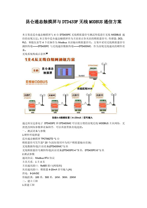
昆仑通态触摸屏与DTD433F无线MODBUS通信方案本方案是昆仑通态触摸屏与4台DTD433FC无线模拟量信号测试终端进行无线MODBUS 通信的实现方法。
本方案中昆仑通态触摸屏作为主站显示各从站的模拟量信号,传感器、DCS、PLC、智能仪表等4个设备作为Modbus从站输出模拟量信号。
方案中采用无线模拟量信号测控终端——DTD433FC与无线通信数据终端——DTD433MC,作为实现无线通讯的硬件设备。
无线系统构成示意图▼通过西安达泰电子DTD433FC和DTD433MC可以很方便的实现无线MODBUS主从网络,无需更改网络参数和设备程序,可以直接替换有线连接。
一、测试设备与参数1.硬件环境搭建昆仑通态触摸屏TPC7062TD *1台模拟量信号发生器* 20个(实际使用中为用户模拟量输出设备)无线数据终端(主站设备)DTD433MC *1块无线模拟量信号测控终端(从站设备)DTD433FC-4 *3块,DTD433FC-8 *1块2.测试参数通讯协议:Modbus RTU协议主从关系:1主4从主站通讯接口:Rs485接口(两线制)从站通讯接口:模拟量4-20mA信号输入(AI)供电:9-24VDC传输距离:100米,500米,1KM,3KM,20KM二、建立工程1.新建工程2.添加设备驱动点击“通用串口父设备”点击设备管理添加“莫迪康ModbusRTU”设备添加结果如下所示“这个是有4个从站”修改通用串口父设备参数修改子设备参数注意设备地址选择三、建立数据通道点击“增加设备通道”添加输入查询对应的数据。
从寄存器3区寄存器地址1开始建立4个设备通道,对应DTD433F 的模拟量输入查询1-4 通道。
点击“快速连接变量”点击“通道处理设置”点击“⑤”设置对应数据四、建立工程画面1.画面控件使用介绍输入查询使用“矩形”. 4个从站,地址分别是1,2,3,4.其中第4个从站是8AI建立如下画面。
依次建立1-4 输入查询通道的画面连接。
工厂无线技改常用的远距离无线开关量信号传输器
工厂无线技改常用的
远距离无线开关量信号传输器
一、D T D509H简介
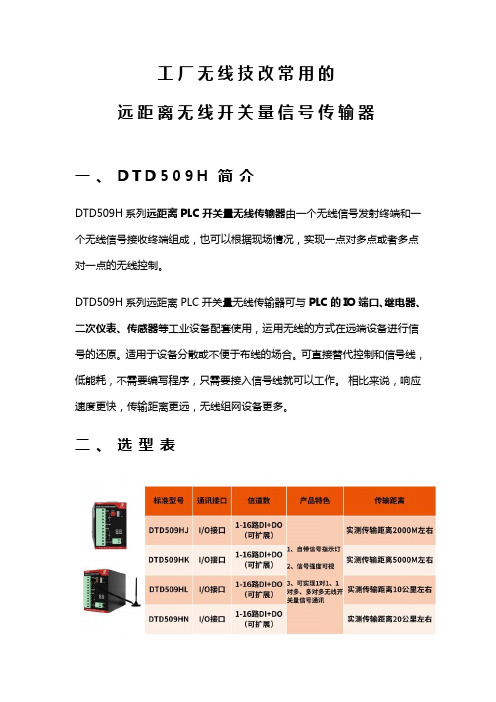
DTD509H系列远距离PLC开关量无线传输器由一个无线信号发射终端和一个无线信号接收终端组成,也可以根据现场情况,实现一点对多点或者多点对一点的无线控制。
DTD509H系列远距离PLC开关量无线传输器可与PLC的IO端口、继电器、二次仪表、传感器等工业设备配套使用,运用无线的方式在远端设备进行信号的还原。
适用于设备分散或不便于布线的场合。
可直接替代控制和信号线,低能耗,不需要编写程序,只需要接入信号线就可以工作。
相比来说,响应速度更快,传输距离更远,无线组网设备更多。
二、选型表
三、用法描述
DTD509H系列PLC开关量信号无线传输器配套PLC、继电器、按钮、报警器等工业设备使用,输入信号可以外接无源触点,干节点。
可以实现点对点及点对多点的远距离开关量信号无线传输通讯
四、应用场景
【应用一】开关量信号1点对多点远距离无线通讯
支持点对点及1点对多点,多路开关量/数字量信号远距离无线传输通讯
【应用二】开关量信号多点对1点之间远距离无线通讯
PLC、泵阀、二次仪表、继电器等I/O开关量信号之间多点对1点无线通讯
【应用三】I/O开关信号之间多对多组网无线通讯
开关量/数字量信号多点对多点无线组网通讯
五、无线方案的优点
采用无线的方式代替有线可以将I/O信号进行远端的还原,不需要物理连接,可以任意时间、地点进行数据传输。
无线信号不但传输速度快,可以大幅提高信息传输效率,而且无需铺设物理线路,节省了布线和维护成本。
无线技术的应用非常广泛,适用于大多数工业场合,大幅度提升了工业自动化的程度。
DTD非属密封调节蝶阀说明书.
录
2
十三、阀门修理指南 7
十四、外形图 8
一、概 述
本阀是适用于汽轮机中低压连通管,作为调节阀门使 用,满足各工况下的连通管的排气流量。设置阀门全关时的最 小流量,以保证阀门异常关闭时,低压缸不产生鼓风发热。
本阀门操作灵活,阀门开启、关闭速度稳定、流阻系数 小,在汽轮机任何工况条件下阀门均不会出现卡涩现象。轴套 与阀轴的设计考虑了高温工况下,材料的膨胀系数,合理的预 留两者之间的间隙,从而防止阀轴与轴套在高温时卡死。
2. 控制阀门时根据DEH控制系统信号(4~20mA)进行抽汽调 控,执行器提供4-20mA阀位反馈。
六、主要外形尺寸和连接尺寸
七、安全提示
1、安装前应仔细核对阀门型号、公称压力、规格是否符合要求,确认
无误后方可安装。当阀门的允许压力和使用温度达不到工况条件的要求 时绝对不能使用,具体的允许值标明在阀门的标牌上。 2、阀门的转轴由多层柔性石墨填料所密封,在松开填料压盖上的螺栓 时,一定要确认,管道里完全没有压力了,不会有介质泄露出来。 3、当阀门必须从管道里拆卸出来时,小心会有介质从管道或阀门里出 来。所以,当介质有害人体或是危险物质时,必须在拆卸阀门前先排空 管道以及小心来自管道或阀门死区的介质。
四、主要零件材料
序号 名称
材质
1
阀体
Q235B
2
蝶板
WCB
3
阀杆
4
轴承
5
填料
6
支架
2Cr13 JF800 柔性石墨 WCB
五、连接形式和动作原理
1.本蝶阀连接形式为法兰式,主要结构是由传动装 置、阀体、蝶板、阀杆等组成。由传动装置带动阀杆与蝶板 在0°至90°范围内作旋转运动,以达到启闭和流量控制的 目的。
DTD金属密封蝶阀说明书资料
406
107
148
153
400
102
216
310
531
331
365
146
400
190
242
248
450
114
222
330
564
369
365
146
400
228
279
292
500
127
229
350
596
404
365
146
400
275
334
363
600
154
267
390
676
473
525
305
400
455
二、型 号 说 明
DT
D
34 3H
16
C
阀门材料: Z 灰铸铁、 Q 球墨铸铁、 C 碳钢、 I 合金钢、 P 铬镍钛钢、 R 铬镍钼钛钢
公称压力: PN6~100、ANSI 150Lb~600Lb 密封面材料: H 堆焊合金、 W 本体不修钢、 Y 硬质合金钢 结构形式: 3 三偏心 连接方式: 4 法兰、 6 对焊、 7 对夹 驱动方式: 3 蜗轮、 6 气动 *、 9 电动 阀门类别: D 蝶阀 功能代号: DT 可调节型
JN-SY2-2009
DTD金属密封蝶阀
使 用 说 明 书
江南阀门
目
一、概述 二、型号说明 三、主要性能参数和执行标准 四、安全提示 五、连接形式和动作原理 六、主要零部件材料 七、外形尺寸和连接尺寸 八、运输与保管 九、阀门的安装 十、压力测试 十一、正常运行与维护 十二、故障排除
DTD 金属密封蝶阀使用说明书
施耐德ZWD414B D415 D416 D433B D432B D433C综合电量变送器使用说明书

ZWD414B/D415/D416/D433B/D432B/D433C 综合电量变送器使用说明书(版本号 V4.1)本文档内容适用于以下型号:ZWD414B—单相综合电量变送器ZWD415—单相交直流电量变送器ZWD416—单相交直流电量变送器(带量程换挡)ZWD433B—三相综合电量变送器ZWD432B—三相综合电量变送器(谐波分析型)ZWD433C—多路综合电量变送器目录1. 产品选型说明 (1)2. 主要技术参数 (6)3. 产品外观、按键及显示窗口 (11)4. 使用前的准备 (12)4.1 测试原理 (12)4.2 安装使用流程 (12)4.3 开机信息说明 (12)4.4 注意事项 (13)5. 基本参数设置 (13)5.1 参数设置 (13)5.2 设置操作示例 (14)6. 使用接线图 (15)7. 串口通讯 (22)8. 扩展功能 (25)8.1 继电器输出功能 (25)8.2 开关量输入功能 (26)8.3 开关量输出功能 (27)9. 装箱清单 (28)10. 注意事项及产品维护 (28)附录1关于Z W D415外置分流器补充说明 (30)1.产品选型说明:表1 产品选型说明表1-1 ZWD414B/D433B功能第 1 页表1-2 ZWD415/ZWD416功能第 2 页表1-3 ZWD432B功能第 3 页表1-4 ZWD433C功能第 4 页表2 其他参数:订货须知:用户在订货前,请确认以下项目:1. 测试参数的范围满足订货产品的量程要求;其它测试范围必须订货时声明。
2. 工作电源:AC (85~265)V,(45~65)Hz;DC (125~250)V;其它要求必须订货声明。
3. 通讯串口默认RS485,MODBUS规约,如需RS232必须订货声明。
4. 扩展功能为选项,非标准配置;用户订货时必需声明。
5. 特制产品测量量程请参照产品标牌,其它特别声明的技术要求或使用要求。
DTDH技术文件(原理等)资料

一、电梯能量回馈装置的工作原理:电梯回馈装置是把电梯在不平衡载荷情况下曳引机所产生的电能经过逆变,变成为与电网同频、同相优质交流电并回馈到局域电网的设备。
供电梯主板、井道及轿厢照明、轿厢风扇等附近有负载的地方(或其它电梯及附属设备)使用。
电梯结构示意图由上示意图或知,电梯由曳引机拖动负载上下运行,而曳引机拖动的负载由轿厢和对重平衡块组成,只有当轿厢载重量约为50%(1吨载客电梯乘客为7人左右)时,轿厢和对重平衡块才相互平衡,否则轿厢和对重就会产生质量差。
电梯运行过程就是电能与机械能转换的过程,当电梯电梯重载上行或轻载下行时,需要给电梯提供能量使机械势能增加,电梯通过曳引机将电能转换为机械势能,曳引机处于耗电状态;当电梯轻载上行或重载下行时,运行过程需要使机械势能减少,电梯机械势能通过曳引机转换为电能,曳引机处于发电状态。
另外电梯在从高速运行到制动停止的过程,是机械动能消耗的过程,其中一部分动能则通过曳引机转换为电能,曳引机也处于发电过程。
曳引机发电过程产生的电能需要及时处理,不然对曳引机有严重的危害。
对于变频电梯,曳引机发电过程产生的电能通过变频器的三相逆变桥反向回到变频器的直流端,存储到储能电容里,而电容的容量有限,当曳引机产生的电能足够大,超过电容的容量,将造成电容损坏,所以多出的电能部分必须消耗掉。
常规的变频电梯处理此部分电能的方法是在电容端加装制动单元和制动电阻,当电容两端的电压到达一定值,制动单元动作,多余的电能通过制动电阻转换为热能散发到空中。
电能回馈装置替代制动单元和制动电阻,通过自动检测变频器的直流母线电压,将变频器的直流环节的直流电逆变成与交流电网同频同相的交流电,经多重噪声滤波环节后连接到交流电网,达到绿色、环保、节能的目的。
二、主要功能:PROPECT-DTDH电梯电能回馈装置是把电梯在不平衡载荷情况下曳引机所产生的电能经过逆变,变成为与电网同频、同相优质交流电返回到局域电网。
达泰电子 DTD433系列工业级无线数传模组 说明书
DTD433系列工业级无线数传模组使用手册铝合金外壳 RS232串口PVC塑料外壳RS232/RS485串口西安达泰电子有限责任公司029-********,85277568, FAX:029-********西安市朱雀大街56号明德门凯旋广场D323E-MAIL:info029@ data029@本公司其他系列产品图片及详细资料,欢迎查看网站 本文档更新日期:2009-01-16 版本号:V3.0该产品在不断改进功能,新增或修改功能的说明以最新版本为准。
恕不另行通知。
目 录一、概述....................................................................................................................................................2二、DTD433数传模组的特性...................................................................................................................32.1 DTD433无线数传模组的技术指标..........................................................................................32.2DTD433无线数传模组的特点..................................................................................................3三、DTD433数传模组的使用方法...........................................................................................................43.1 DTD433X_S塑壳数传模组与终端设备的连接......................................................................43.2 DTD433X_L铝壳数传模组与终端设备的连接......................................................................83.3 天线配置..................................................................................................................................9四、DTD433工业级数传模组的应用...................................................................................................104.1 选择无线监控的优势..........................................................................................................104.2无线数传模块、模组和电台的区别...................................................................................104.3 无线数传模组的通信..........................................................................................................114.4 模组应用领域......................................................................................................................12五、使用注意事项................................................................................................................................12六、质量保证........................................................................................................................................12七、常见故障及解决方法....................................................................................................................13首先,感谢您选用DTD433工业级无线数传模组,我公司将一如既往地为您提供优质的产品和服务!敬告用户,请您在使用前,仔细阅读本手册!本手册适用于DTD433工业级无线数传模组,阅读时请您留意各型号的备注。
迅迪电子 XD308H 宽输入电压范围降压型 DC DC 转换器规格书说明书
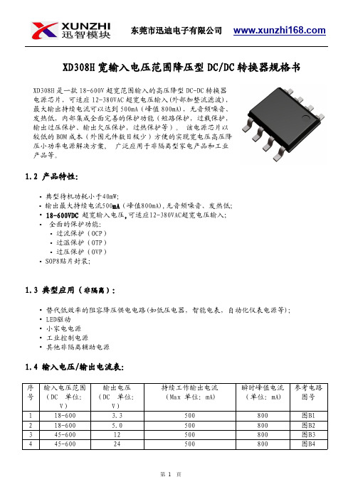
XD308H 宽输入电压范围降压型DC/DC 转换器规格书1.2产品特性:•典型待机功耗小于40mW;•输出最大持续电流500mA (峰值800mA),无音频噪音、发热低;•18-600VDC 超宽输入电压,可适应12-380VAC超宽电压输入;•全面的保护功能:•过流保护(OCP)•过温保护(OTP)•过压保护(OVP)•SOP8贴片封装;1.3典型应用(非隔离):•替代低效率的阻容降压供电电路(如低压电器,智能电表,自动化仪表电源等);•LED驱动•小家电电源•工业控制电源•其他非隔离辅助电源1.4输入电压/输出电流表:序号输入电压范围(DC 单位:V)输出电压(DC 单位:V)持续工作输出电流(Max 单位:mA)瞬时峰值电流(单位:mA)参考电路图号118-600 3.3500800图B1218-600 5.0500800图B2345-60012500800图B3445-60024500800图B4XD308H 是一款18-600V 超宽范围输入的高压降型DC-DC 转换器电源芯片,可适应12-380VAC 超宽电压输入(外部加整流滤波),最大输出持续电流可以达到500mA(峰值800mA),无音频噪音、发热低,内部集成全面完善的保护功能(短路保护,过载保护,输出过压保护、输出欠压保护,过热保护等)。
该电源芯片以较低的BOM 成本(外围元件数目极少)方便的实现宽电压高压降压小功率电源解决方案,广泛应用于非隔离型家电产品和工业产品等。
1.5封装参考:1.6引脚功能:编号名称描述备注1VCC/BP所有控制电路的电源。
外部旁路电容连接点2GND/S芯片参考地。
内部功率MOSFET的源极。
3FB反馈输入4CS电流检测5,6,7,8DRAIN内部功率MOSFET的漏极1.7功能框图:图11.8典型应用电路:1.9绝对最大额定值(备注1):1.10推荐的工作条件(备注2):参数数值单位工作环境温度-40to85°C1.11电气特性:=+25℃。
DTD 系列温度控制器 说明书
րЕޘଠטጡፆү͘Ί!非常感谢您选用台达产品,请在使用前,详细阅读本使用说明书,并将手册放置于易拿处以便参考。
ڦຍְีڦຍĊᑝПᐍĊ当电源上电时,请勿触摸AC接线端,以免遭致电击。
检查输入电源时,请确认电源是关闭的。
本机为开放型装置,因此当要使用在危险的应用场合,如:会造成人员严重伤害及其它设备损坏,请确认将其安装至自动故障安全防护装置设备上。
1. 请使用适合M3螺丝的压接端子(最大宽度7.2mm),端子螺丝在锁紧时请勿过度用力。
确认配线接到正确适当的端子。
2. 如果有尘土或金属残渣掉入机身,可能会造成误动作。
请勿修改或擅自拆卸本控制器。
空余端子请勿使用。
3. 安装时离开高电压及具有强高周波噪声的地方以防止干扰。
在会发生以下情况的场所避免使用此控制器:(a) 灰尘过多及有腐蚀性气体;(b) 高湿度及高辐射;(c) 震动及冲击。
4. 实施配线时和更换温度传感器时,务必关闭电源。
5. 热电偶对的引线要延长时或有结线的场合请依热电偶对的种类务必使用补偿导线。
6. 白金测温阻抗体的引线延长时或有结线的场合,请使用阻抗体的物体。
7. 由测温体到控制器本体的配线路请用最短距离配线,为了避免噪声及诱导的影响尽可能把电源线和负载配线分开。
8. 本机器为开放型机壳,必须安装在具防尘、防潮及免于电击∕冲击的外壳配电箱内。
9. 上电前请确认电源∕信号装配是否正确,否则可能造成严重损坏。
10. 上电时请勿接触机体端子或进行维修,否则可能遭致电击。
11. 切断电源一分钟之内,线路未完全放电,请勿接触内部线路。
请使用干布清洁本机器,勿使用含有酸、碱的液体清洁。
யݡొҜЩჍ!PV: 输入显示值/功能项目显示(红色七段显示器)SV: 设定值显示(绿色七段显示)AT: PID自动调整时闪烁(绿色LED)OUT: 输出动作时亮灯(绿色LED)ALM: 警报动作时亮灯(红色LED): 模式选择及设定完成键: 功能选项及数字左移键!: 向上循环调整键Ᏼᔉܫि!DTD012345ঈఢॾ输入电源交流电100 ~ 240V, 50/60Hz操作电压范围额定电压85% ~ 110%电源消耗功率 6VAMax.显示方法七段LED显示;目前温度值:红色,设定温度值:绿色输入温度传感器热电偶对:K、J、T、E、N、R、S、B、U、L、Txk白金测温电阻:Pt100、JPt100铜测温电阻:Cu50模拟输入电流:0 ~ 20mA、4 ~ 20mA 电压:0 ~ 5V、0 ~ 10V、0 ~ 70mV显示刻度温度输入K2、J2、T2、Pt100-2、JPt100、Cu50可显示0.1度,其它以1度为单位。
TDK 电磁感应器 TAJ333333 产品说明书
Dimensions: [mm]Scale- 2.5:1BC7893181251578931812515T e m p e r a t u r eT pT L78931812515Cautions and Warnings:The following conditions apply to all goods within the product series of WE-PSPA ofWürth Elektronik eiSos GmbH & Co. KG:General:•This electronic component is designed and manufactured for use in general electronic equipment.•Würth Elektronik must be asked for written approval (following the PPAP procedure) before incorporating the components into any equipment in fields such as military, aerospace, aviation, nuclear control, submarine, transportation (automotive control, train control, ship control), transportation signal, disaster prevention, medical, public information network etc. where higher safety and reliability are especially required and/or if there is the possibility of direct damage or human injury.•Electronic components that will be used in safety-critical or high-reliability applications, should be pre-evaluated by the customer. •The component is designed and manufactured to be used within the datasheet specified values. If the usage and operation conditions specified in the datasheet are not met, the wire insulation may be damaged or dissolved.•Do not drop or impact the components, as the component may be damaged.•Würth Elektronik products are qualified according to international standards, which are listed in each product reliability report. Würth Elektronik does not warrant any customer qualified product characteristics beyond Würth Elektroniks’ specifications, for its validity and sustainability over time.•The responsibility for the applicability of the customer specific products and use in a particular customer design is always within the authority of the customer. All technical specifications for standard products also apply to customer specific products.Product specific:Soldering:•The solder profile must comply with the technical product specifications. All other profiles will void the warranty.•All other soldering methods are at the customers’ own risk.•Strong forces which may affect the coplanarity of the components’ electrical connection with the PCB (i.e. pins), can damage the component, resulting in avoid of the warranty.Cleaning and Washing:•Washing agents used during the production to clean the customer application might damage or change the characteristics of the wire insulation, marking or plating. Washing agents may have a negative effect on the long-term functionality of the product.•Using a brush during the cleaning process may break the wire due to its small diameter. Therefore, we do not recommend using a brush during the PCB cleaning process.Potting:•If the product is potted in the customer application, the potting material might shrink or expand during and after hardening. Shrinking could lead to an incomplete seal, allowing contaminants into the core. Expansion could damage the component. We recommend a manual inspection after potting to avoid these effects.Storage Conditions:• A storage of Würth Elektronik products for longer than 12 months is not recommended. Within other effects, the terminals may suffer degradation, resulting in bad solderability. Therefore, all products shall be used within the period of 12 months based on the day of shipment.•Do not expose the components to direct sunlight.•The storage conditions in the original packaging are defined according to DIN EN 61760-2.•The storage conditions stated in the original packaging apply to the storage time and not to the transportation time of the components. Packaging:•The packaging specifications apply only to purchase orders comprising whole packaging units. If the ordered quantity exceeds or is lower than the specified packaging unit, packaging in accordance with the packaging specifications cannot be ensured. Handling:•Violation of the technical product specifications such as exceeding the nominal rated current will void the warranty.•Applying currents with audio-frequency signals may result in audible noise due to the magnetostrictive material properties.•Due to heavy weight of the components, strong forces and high accelerations may have the effect to damage the electrical connection or to harm the circuit board and will void the warranty.•The temperature rise of the component must be taken into consideration. The operating temperature is comprised of ambient temperature and temperature rise of the component.The operating temperature of the component shall not exceed the maximum temperature specified.•Dielectric isolation may be reduced over time and prolonged use.These cautions and warnings comply with the state of the scientific and technical knowledge and are believed to be accurate and reliable.However, no responsibility is assumed for inaccuracies or incompleteness.Würth Elektronik eiSos GmbH & Co. KGEMC & Inductive SolutionsMax-Eyth-Str. 174638 WaldenburgGermanyCHECKED REVISION DATE (YYYY-MM-DD)GENERAL TOLERANCE PROJECTIONMETHODPaC002.0012023-04-04DIN ISO 2768-1mDESCRIPTIONWE-PSPA Push Pull TranformerORDER CODE78931812515SIZE/TYPE BUSINESS UNIT STATUS PAGEImportant NotesThe following conditions apply to all goods within the product range of Würth Elektronik eiSos GmbH & Co. KG:1. General Customer ResponsibilitySome goods within the product range of Würth Elektronik eiSos GmbH & Co. KG contain statements regarding general suitability for certain application areas. These statements about suitability are based on our knowledge and experience of typical requirements concerning the areas, serve as general guidance and cannot be estimated as binding statements about the suitability for a customer application. The responsibility for the applicability and use in a particular customer design is always solely within the authority of the customer. Due to this fact it is up to the customer to evaluate, where appropriate to investigate and decide whether the device with the specific product characteristics described in the product specification is valid and suitable for the respective customer application or not.2. Customer Responsibility related to Specific, in particular Safety-Relevant ApplicationsIt has to be clearly pointed out that the possibility of a malfunction of electronic components or failure before the end of the usual lifetime cannot be completely eliminated in the current state of the art, even if the products are operated within the range of the specifications.In certain customer applications requiring a very high level of safety and especially in customer applications in which the malfunction or failure of an electronic component could endanger human life or health it must be ensured by most advanced technological aid of suitable design of the customer application that no injury or damage is caused to third parties in the event of malfunction or failure of an electronic component. Therefore, customer is cautioned to verify that data sheets are current before placing orders. The current data sheets can be downloaded at .3. Best Care and AttentionAny product-specific notes, cautions and warnings must be strictly observed. Any disregard will result in the loss of warranty.4. Customer Support for Product SpecificationsSome products within the product range may contain substances which are subject to restrictions in certain jurisdictions in order to serve specific technical requirements. Necessary information is available on request. In this case the field sales engineer or the internal sales person in charge should be contacted who will be happy to support in this matter.5. Product R&DDue to constant product improvement product specifications may change from time to time. As a standard reporting procedure of the Product Change Notification (PCN) according to the JEDEC-Standard inform about minor and major changes. In case of further queries regarding the PCN, the field sales engineer or the internal sales person in charge should be contacted. The basic responsibility of the customer as per Section 1 and 2 remains unaffected.6. Product Life CycleDue to technical progress and economical evaluation we also reserve the right to discontinue production and delivery of products. As a standard reporting procedure of the Product Termination Notification (PTN) according to the JEDEC-Standard we will inform at an early stage about inevitable product discontinuance. According to this we cannot guarantee that all products within our product range will always be available. Therefore it needs to be verified with the field sales engineer or the internal sales person in charge about the current product availability expectancy before or when the product for application design-in disposal is considered. The approach named above does not apply in the case of individual agreements deviating from the foregoing for customer-specific products.7. Property RightsAll the rights for contractual products produced by Würth Elektronik eiSos GmbH & Co. KG on the basis of ideas, development contracts as well as models or templates that are subject to copyright, patent or commercial protection supplied to the customer will remain with Würth Elektronik eiSos GmbH & Co. KG. Würth Elektronik eiSos GmbH & Co. KG does not warrant or represent that any license, either expressed or implied, is granted under any patent right, copyright, mask work right, or other intellectual property right relating to any combination, application, or process in which Würth Elektronik eiSos GmbH & Co. KG components or services are used.8. General Terms and ConditionsUnless otherwise agreed in individual contracts, all orders are subject to the current version of the “General Terms and Conditions of Würth Elektronik eiSos Group”, last version available at .Würth Elektronik eiSos GmbH & Co. KGEMC & Inductive SolutionsMax-Eyth-Str. 174638 WaldenburgGermanyCHECKED REVISION DATE (YYYY-MM-DD)GENERAL TOLERANCE PROJECTIONMETHODPaC002.0012023-04-04DIN ISO 2768-1mDESCRIPTIONWE-PSPA Push Pull TranformerORDER CODE78931812515SIZE/TYPE BUSINESS UNIT STATUS PAGE。
新晟显示电子有限公司 NHD-0420DZW 蓝色 OLED 字符显示模块 产品说明书
NHD-0420DZW-AB5 Character OLED Display ModuleNHD- Newhaven Display0420- 4 lines x 20 charactersDZW- OLEDA- ModelB- Emitting Color: Blue5- +5V power supplyRoHS CompliantNewhaven Display International, Inc.2661 Galvin Ct.Elgin IL, 60124Ph: 847-844-8795 Fax: 847-844-8796Functions and Features• 4 lines x 20 characters•Built-in LCD comparable controller•Parallel or serial MPU interface (Default 6800 MPU parallel) •+5.0V Power Supply•Size compatible to NHD-0420DZ series Character LCDs•RoHS compliant[2]Pin Description[4][5]Wiring DiagramsNote:1)Lifetime at typical temperature is based on accelerated high-temperature operation. Lifetime is tested at average 50%pixels on and is rated as hours until half-brightness. The Display OFF command can be used to extend the lifetime of the display.2)Luminance of active pixels will degrade faster than inactive pixels. Residual (burn-in) images may occur. To avoid this,every pixel should be illuminated uniformly. Using a screensaver is highly recommended.3)Brightness is related to the VDD, the brightness will be dimmer if used with lower voltages.[6]Table of Commands[7]Instruction DescriptionsWhen an instruction is being executed, only the Busy Flag read instruction can be performed. During execution of an instruction, the Busy Flag = “1”. When BF = “0” instructions can be sent to the controller.DDRAM Address.on) will be at the first line’s left-most character. The DDRAM contents on the display do not change.When I/D = “1”, the DDRAM or CGRAM Address with automatically increment when a character code is written into or read from the DDRAM or CGRAM. The auto-increment will move the cursor one-character space to the right.When I/D = “0”, the DDRAM or CGRAM Addr ess with automatically decrement when a character code is written into or read from the DDRAM or CGRAM. The auto-decrement will move the cursor one-character space to the left.S = Shift Entire DisplayWhen S = “1”, the entire display is shifted to the right (when I/D = “0”) or left (when I/D = “1”).I/D=1, S=1I/D=0, S=1[8]When D = “1”, the display is turned ON. When D = “0”, the display is turned OFF. Contents in DDRAM are not changed.C = Cursor ON/OFFWhen C = “1”, the cursor is displayed. The cursor is displayed as 5 dots on the 8th line of a character. When C = “0”, th e cursor is OFF.B = Blinking CursorWhen B = “1”, the entire character specified by the cursor blinks at a speed of 409.6ms intervals. When B = “0”, the character does not blink, the cursor remains on.When the display is shifted repeatedly, each line moves only horizontally. The second line display does not shift into the first line.The Address Counter does not change during a Display Shift.When DL = “1”, the data is sent or received in 8-bit length via DB7...DB0.When DL = “0”, the data is sent or received in 4-bit length via DB7...DB4. When the 4-bit data length is used, the data must be sent or received in two consecutive writes/reads to combine the data into full 8-bits.FT1, FT0 = Font Table SelectionNote: Changing the font table during operation will immediately change any data currently on the display to the corresponding character on the newly selected font table.[9]the CGRAM locations. See section: “How to use CGRAM”.ACG5...ACG0 is the binary CGRAM address.the DDRAM locations.ADD6...ADD0 is the binary DDRAM address.Line 1 = Address 0x00 through 0x13Line 2 = Address 0x40 through 0x53Line 3 = Address 0x14 through 0x27Line 4 = Address 0x54 through 0x67The Address Counter is read simultaneously with checking the Busy Flag.When BF = “1”, the controller is busy and the next instruction will be ignored.When BF = “0”, the controller is not busy and is ready to accept instructions.AC6...AC0 is the binary location of either the CGRAM or DDRAM current address.complete, the address is automatically incremented or decremented by 1 according to the Entry Mode.complete, the address is automatically incremented or decremented by 1 according to the Entry Mode.The Set CGRAM Address or Set DDRAM Address Instruction must be executed before this instruction can be performed, otherwise the first Read Data will not be valid.[10]MPU InterfaceWhen DL is set for 8-bit mode, the display interfaces with the MPU with DB7...DB0 (DB7 is the MSB).When DL is set for 4-bit mode, the display interfaces with the MPU with only DB7...DB4 (DB7 is the MSB). Each instruction must be sent in two operations, the 4 high-order bits first, followed by the 4 low-order bits. The Busy Flag must be checked after completion of the entire 8-bit instruction.6800-MPU Parallel Interface (default)[11]8080-MPU Parallel Interface[12][13]Serial InterfaceIn serial interface mode, instructions and data are both sent on the SDI line and clocked in with the SCL line./CS must go LOW before transmission, and must go HIGH when switching between writing instructions and writing data. The data on SDI is clocked into the LCD controller on the rising edge of SCL in the following format:Instruction transmission:*Note: RS and RW should be used between each instruction.Data transmission:*Note: RS and RW only need to be set at the start of continuous data transmission.[14]Built-in Font TablesEnglish/Japanese (FT[1:0] = 00, default)[15]Western European table 1 (FT[1:0] = 01)[16]English/Russian (FT[1:0] = 10)[17]Western European table 2 (FT[1:0] = 11)[18]How to use CGRAMThe Character Generator RAM (CGRAM) is used to generate custom 5x8 character patterns. There are 8 available addresses: CGRAM Address 0x00 through 0x08.“-” = Not usedThe cursor line position can be used, it will be displayed as a logic-OR if the cursor is turned ON.CGRAM is stored in positions 0x00 through 0x07 of the font table. Therefore, to write the first CGRAM character to the display, you would move the cursor to the desired DDRAM location on the display and write character data 0x00.[19]Initialization Sequence4-bit mode:[20][21]Note 2: Conducted after 2 hours of storage at 25⁰C, 0%RH.Note 3:Test performed on product itself, not inside a container.Evaluation Criteria:1: Display is fully functional during operational tests and after all tests, at room temperature. 2: No observable defects.3: Luminance >50% of initial value.4: Current consumption within 50% of initial valuePrecautions for using OLEDs/LCDs/LCMsSee Precautions at /specs/precautions.pdfWarranty Information and Terms & Conditions/index.php?main_page=terms[22]。
浙江恒旺电子有限公司产品说明书
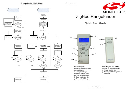
RangeFinder Work Flow/telegesissupportZigBee RangeFinderQuick Start Guide(h)(i)(j)(a)(b)(e(g)Handheld (HHT)(a) Product Model Number (b) LCD Display (c) Navigation Keys (d) Value Change Keys (e) Escape (Back) Key (f) Enter (Activate) Key (g) Power On/Off KeySatellite (IHD and GAS) (h) Product Model Number (i) Power On/Off Key(j) Activity and Battery Status IndicatorIssue: 4Date: Aug 2013 Start GuidePre -TestThis is used to test the link between the Range Finder handheld unit and the satellites IHD and GAS.The results are shown in the following screen and include: ∙ Serial number of the IHD or GAS unit. ∙ Battery capacity at IHD and GAS units. ∙ RSSI level measure during the Pre -Test.∙ Overall result of ‘OK’ or ‘NOK’ for Pre -Test Pass orFail.The bottom row shows:∙ The Zigbee RF channel used for Pre -Test. ∙ The transmit power used for Pre -Test. ∙ The battery status of handheld unit.Pre -Test transfers all the test settings from HHT to the IHD and GAS units for current session, so it is important to get an OK from this test in order to perform any further tests. Press ESC key to exit the test and go back to menu screen.Data Logging Configuration (Data Logger)The HHT will record the results from Test -A/B and Energy Scan into built -in storage. After exiting the welcome screen the data logging config screen will appear which enables the operator to enter the SITE ID for the current session. The SITE ID will be stored with the test results of the cur-rent session (more details in the user manual). At every new site, changethe SITE ID by navi-gating to EDIT option on screen using keys and press OK. The SITE ID is an alphanumeric field of 16 characters and can be edited by using keys.Once the SITE ID is changed press OK key on keypad to hear a beep from device as confirmation.Please enter a unique SITE ID for each location as this is used as record identifier in the data logs. This option can also be accessed by selecting “Data Logger” menu option on Menu Screen 2.Main Menu Screen 1Use navigation keys to scroll through various menuTo use both IHD and GAS for test. To use only IHD for test.Press OK to use the setting for the current session or to select any menu option.The battery symbol indicates the capacity or charging status of the battery of the handheld. Further details of Menu Screen 2 options can be found in the user manual. Using the Range Finder Power On/Off∙ To power on press the Power Key (g) for about 3 sec-onds until the Welcome Screen is displayed∙ To power off press the Power Key (g) until the screengoes blankWelcome ScreenUpon power up the welcome screen pops up displaying information about the device firmware and the serial num-bers of devices paired as shown below. Press any key to exit from this screen.IG I Specifications:RF Interface:Wireless Standard: 2.4GHz IEEE802.15.4 Output Power: - 9 to +8dBmRF Channels: 11,14,15,19,20,24,25Antenna:Half Wave Dipole Antenna with 2dBi GainElectrical:Battery HandheldType: 2x 1.2V 2000mAH NiMH rechargeable Expected Life: 5 Days [150 x 15 min cycles] Charging: 5 Volts @ 300mAvia USB Micro Connector Battery SatelliteType: 2x 1.5V AlkalineExpected Life: 5 Days [150 x 15 min cycles]Environmental:Operating Temperature: 0 to 50C Humidity: 95% RH non -condensing IP Rating: IP54Test BTest B is similar to Test A except it tests the link between the HHT and the IHD and GAS units on channels 20,24 and 25. The result screen is as shown:Energy ScanAn energy scan across all channels specified by the 2.4GHz 802.15.4 standard is performed and the result is shown. The Energy Scan results for each channel are painted on the screen as the scan progresses.The channel number ‘0’ corresponds to channel 11 of the ZigBee 2.4GHz RF spectrum. The channels which are tested in Test A and B are highlighted.Configuration Settings Screen (Config)Usenavigation keys to scroll through different set-tings.Press OK to select the set-ting andkeys to edit it.Once edited again press OK to set the value for the configu-ration setting. If the value is set correctly the device will beep once to con-firm changein setting.The ‘CDT’ option has a valid range of 10 to 120 seconds. This value is the countdown time used during Test A and Test B. if this setting is changed here, the change will be volatile (i.e. CDT will be reset to the default value after power up) The PIN protected configuration settings aredescribed in detail in the user manual.The RangeFinder has 10 built -in profiles of all the settings which are required to perform tests which could be assigned to each device (HHT/IHD/GAS) individually. To assign the setting to any device navigate to the device name using keys and press OK. Test ATest A checks the link between HHT and the IHD and GAS units on channels 11,14,15 and 19. At the start of test a countdown timer gives the operator a chance to place the HHT unit in the test location and move away. Count down time can be changed in the Configuration Settings Screen.or cross respectively in the right hand which failed is highlighted. The red backlight turns ON if link failure occurs on two or more channels.Values under label ‘T’ - RSSI in dBm at HHT ‘S’ - RSSI in dBm at SATNote : On all menu screens the keys will adjust the contrast of the display . Be careful while changing the contrast as it might lead to a blank or completely dark screen.。
AHTT2820高精密温湿度传感器产品说明书
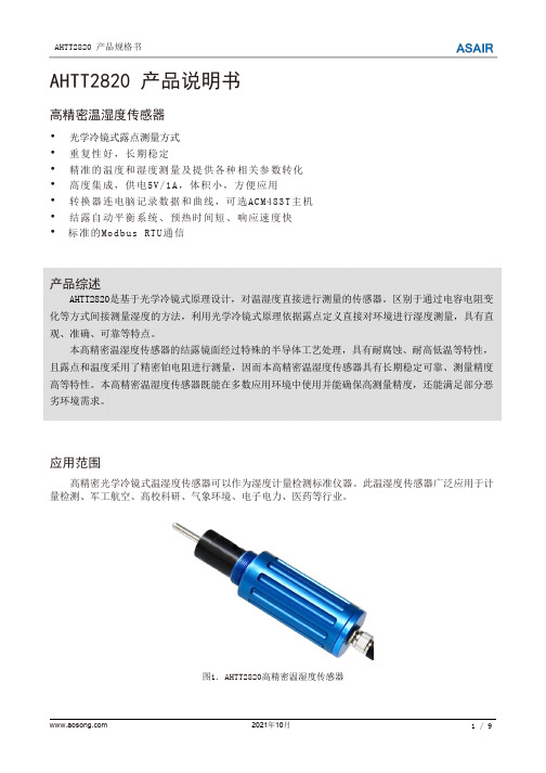
AHTT2820产品说明书高精密温湿度传感器•光学冷镜式露点测量方式•重复性好,长期稳定•精准的温度和湿度测量及提供各种相关参数转化•高度集成,供电5V/1A,体积小,方便应用•转换器连电脑记录数据和曲线,可选ACM483T主机•结露自动平衡系统、预热时间短、响应速度快•标准的Modbus RTU通信产品综述AHTT2820是基于光学冷镜式原理设计,对温湿度直接进行测量的传感器。
区别于通过电容电阻变化等方式间接测量湿度的方法,利用光学冷镜式原理依据露点定义直接对环境进行湿度测量,具有直观、准确、可靠等特点。
本高精密温湿度传感器的结露镜面经过特殊的半导体工艺处理,具有耐腐蚀、耐高低温等特性,且露点和温度采用了精密铂电阻进行测量,因而本高精密温湿度传感器具有长期稳定可靠、测量精度高等特性。
本高精密温湿度传感器既能在多数应用环境中使用并能确保高测量精度,还能满足部分恶劣环境需求。
应用范围高精密光学冷镜式温湿度传感器可以作为湿度计量检测标准仪器。
此温湿度传感器广泛应用于计量检测、军工航空、高校科研、气象环境、电子电力、医药等行业。
图1.AHTT2820高精密温湿度传感器1.传感器原理露点是指水或冰汽化成气态的最大程度(即饱和水汽压)时所对应的温度。
通常气体中实际水汽压在环境温度降到该水汽压对应的露点温度以下时,水汽会凝结成露或霜。
相对湿度是指在一定温度下,实际水汽含量(水汽压)与该温度下理论饱和水汽含量(水汽压)之比。
冷镜式露点系统是利用半导体制冷片控制镜面温度变化,当含水汽的气体通过镜面时,水汽在镜面表面出现结露或结霜,再经过检测结露或结霜的厚度进行自动调节镜面温度,直到结露或结霜的厚度稳定,从而检测出镜面结露或结霜稳定后的温度的智能系统。
冷镜式露点系统是利用半导体制冷片控制镜面温度变化检测出镜面结露或结霜稳定后的温度的智能系统。
当含水汽的气体通过镜面时,在镜面表面出现结露或结霜。
经过检测结露或结霜的厚度进行自动调节镜面温度,直到结露或结霜的厚度稳定在系统的设定值。
T-ASK433-D4 深圳市骏晔科技有限公司版本1.0测试板使用说明书

T-ASK433-D4深圳市骏晔科技有限公司Version1.0T-ASK433-D4测试板使用说明书一、产品介绍:T-ASK433-D4开发工具包含有:四键发射遥控器+接收测试底板+学习码接收模块+高增益天线,可以直接应用于各种场景的演示以及距离、性能测试。
二、产品特点:●频率:433.92MHZ(特殊频点可定制)●灵敏度高达:-112dBm●电源电压输入范围:2.8V-5.5V(推荐工作电压3.3V或5.0V)●锁存与非锁存模式选择:设置T1、T2解码输出锁存/非锁存●可配套学习PT2260、2262、1527遥控器,速率兼容性好●编码数据传输速率 2.5K bps(曼彻斯特编码)●OOK调制模式,可配合PT4450、115H、113、R25(2SK3356)等多种发射电路●模块尺寸28.5×12×6mm(A版)、28.5×12×6mm(B版T型板)三、技术参数:参数符号状态参考值单位最小标准最大工作频率Fc315,433.92MHz 调制方式ASK接收灵敏度50欧姆天线直接输入/1k Kbps-112dBm RF接收带宽300KHz 数据解调带宽解调脉冲宽度为0.2-1ms1 2.5K 接收开启时间T on ms 工作电压VDD 2.8 3.3或5.0 5.5V 工作电流IRC VDD=3.3V/315M 3.9mAVDD=3.3V/433M6mA逻辑真值表T1T2状态说明M闪动模式高电平(悬空)高电平(悬空)T1、T2两个设置端口悬空,不接任何电平L自锁模式高电平(悬空)低电平(接地)D0-D3独立输出锁存状态,遇有效信号翻转H互锁模式低电平(接地)高电平(悬空)D0-D3互锁输出,当前信号输出保持唯一性预留模式低电平(接地)低电平(接地)可定制其他功能模式(暂未使用)注明:红色DK工具板,每次设置T1、T2状态后需要重新上电复位,确认设置[器件简介]四、适用型号模块:注意:测试版顶部有三组引脚口,请根据模块引脚对应焊接。
化工厂多处4-20mA信号无线采集
化工厂多处4-20mA信号无线采集
■需求描述
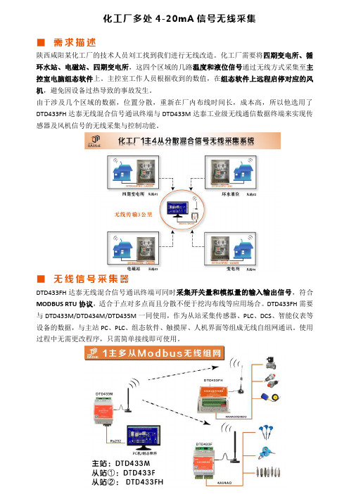
陕西咸阳某化工厂的技术人员刘工找到我们进行无线改造。
化工厂需要将四期变电所、循环水站、电磁站、四期变电所,这四个区域的几路温度和液位信号通过无线方式采集至主控室电脑组态软件上。
主控室工作人员根据收到的数值,在组态软件上远程启停对应的风机,避免因设备过热导致的事故发生。
由于涉及几个区域的数据,位置分散,重新在厂内布线时间长,成本高,所以他选用了DTD433FH达泰无线混合信号通讯终端与DTD433M达泰工业级无线通信数据终端来实现传感器及风机信号的无线采集与控制功能。
■无线信号采集器
DTD433FH达泰无线混合信号通讯终端可同时采集开关量和模拟量的输入输出信号,符合MODBUS RTU协议,适合于点对多点而且分散不便于挖沟布线等应用场合。
DTD433FH需要与DTD433M/DTD434M/DTD435M一同使用,作为从站采集传感器、PLC、DCS、智能仪表等设备的数据,与主站PC、PLC、组态软件、触摸屏、人机界面等组成无线自组网通讯。
使用过程中无需更改程序,只需简单接线即可使用。
基德电控头产品说明书

A UTC Fire & Security CompanyThis literature is provided for informational purposes only. KIDDE-FENWAL, INC. assumes no responsibility for the product’s suitability for a particular application. The product must be properly applied to work correctly.If you need more information on this product, or if you have a particular problem or question, contact KIDDE-FENWAL, INC., Ashland, MA 01721. Telephone: (508) 881-2000.Kidde Fire SystemsA UTC Fire & Security Company 400 Main Street Ashland, MA 01721Ph: 508.881.2000Fax: 508.881.8920K-45-8017 Rev AB© 2007 Kidde-Fenwal Inc.Printed in USAFEATURES•For Use with UL Listed, ULC Listed, and FM Approved SystemsP/N: 486500-01Note:This control head is polarized. Improper wiring will result in operational failure of this device.TECHNICAL DATA •Voltage: 24 Vdc•Current: 0.2 A Continious DrawElectric Control Head, P/N 486500-01, is designed for installation directly on Novec 1230 valves only. This control head must not be installed on any other type ofcylinder valve, or stop (directional) valves. Installation of this control head to any other device (e.g., pressure operated control head) will result in failure of the device to operate.CAUTIONThe Stackable Control head, P/N 486500-1, cannot be used with the 3-inch valve cylin-ders (P/Ns 45-100600-001, 45-100601-001, 45-100900-001, and 45-100901-001). The stackable control head does not have suffi-cient force to activate the 3-inch valve and may result in a system failure. The electric/manual control heads (P/Ns 890181,890149, 890165, and 81-100000-001) may be used with the 3-inch valve.Kidde is a registered trademark of Kidde-Fenwal, Inc.3M and Novec are trademarks of 3M.All other trademarks are property of their respective owners.。
DTD433H产品说明

无线开关量终端产品DTD433H_无需挖沟布线,直接替代PLC 、无线距离可达3000米!DTD433H无线开关量终端相当于一个4路开关输入和4路开关输出的无线PLC主机,它提供了4DI和4DO,符合MODBUS RTU协议,无线可靠传输距离在3000米范围内。
DTD433H产品既可以实现点对点通信,也适合于点对多点而且分散不便于挖沟布线等应用场合。
DTD433H不仅能与PLC、DCS、智能仪表等设备组成无线测控系统,同时能与组态软件、人机界面、触摸屏等工控产品实现达泰自由协议、MODBUS协议的组态,为工业测控领域提供了中短距离无线通信的低成本解决方案。
■ 主 要 特 征:◆ 开关量输入:4通道DI输入,TTL电平或者无源触点均可◆ 开关量输出:4通道DO输出,OC门输出,可以外接直流继电器线包◆ 可以直接代替有线的RS485网,实现无线组网◆ 有效无线传输距离可有三种选择:300米、1000米、3000米左右◆ ISM 开放频段433MHz,无需申请频点◆ 直流9~24V(1A)供电,平均工作电流小于50mA◆ PVC塑料外壳:115×74×60mm,E型导轨卡槽安装◆ 支持标准串口协议:达泰自由串口协议、Modbus RTU协议◆ 八年工业现场运行考验:可确保工作于各种恶劣环境工业场合长期运行■ 应 用 实 例:DTD433H工业级无线开关量终端可以直接替代PLC有线方案,并支持自由串口协议、Modbus RTU协议;彻底解决有线方案施工繁琐、设备后期维护成本高难题。
可以直接组态,与组态软件、PLC、触摸屏及智能仪表连接,无需挖沟布线,已经成功的应用有:◆ 工业场合的无线遥控遥测;◆ 直接代替西门子PLC的无线通信;◆ 工厂改造项目,随时增加无线开关监控点;◆ 无线远程开关控制;◆ 工业设备故障无线报警。
■ 订 货 信 息:产品型号 说明DTD433MA_S 无线主控模块,透明传输RS232、RS485接口,塑料PVC外壳,200米以内。
点对点无线开关量信号传输器
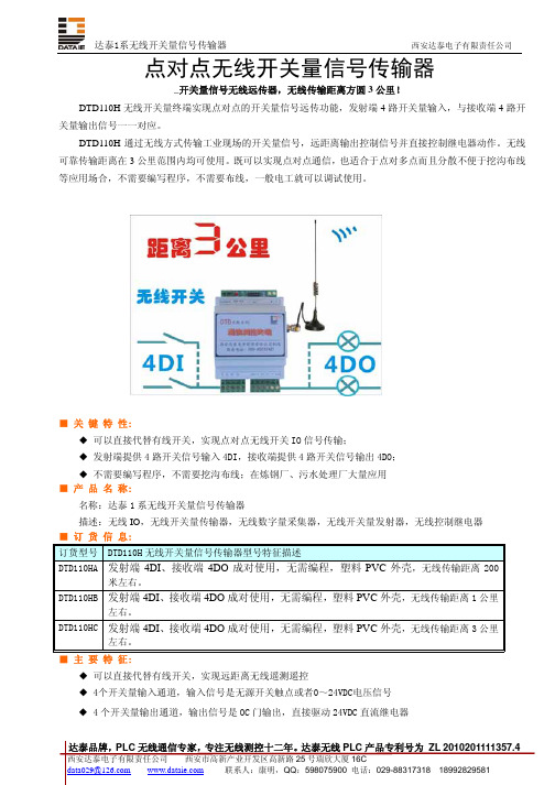
点对点无线开关量信号传输器_开关量信号无线远传器,无线传输距离方圆3公里!DTD110H无线开关量终端实现点对点的开关量信号远传功能,发射端4路开关量输入,与接收端4路开关量输出信号一一对应。
DTD110H通过无线方式传输工业现场的开关量信号,远距离输出控制信号并直接控制继电器动作。
无线可靠传输距离在3公里范围内均可使用。
既可以实现点对点通信,也适合于点对多点而且分散不便于挖沟布线等应用场合,不需要编写程序,不需要布线,一般电工就可以调试使用。
■ 关 键 特 性:◆ 可以直接代替有线开关,实现点对点无线开关IO信号传输;◆ 发射端提供4路开关信号输入4DI,接收端提供4路开关信号输出4DO;◆ 不需要编写程序,不需要挖沟布线;在炼钢厂、污水处理厂大量应用■ 产 品 名 称:名称:达泰1系无线开关量信号传输器描述:无线IO,无线开关量传输器,无线数字量采集器,无线开关量发射器,无线控制继电器■ 订 货 信 息:订货型号 DTD110H无线开关量信号传输器型号特征描述DTD110HA 发射端4DI、接收端4DO成对使用,无需编程,塑料PVC外壳,无线传输距离200米左右。
DTD110HB 发射端4DI、接收端4DO成对使用,无需编程,塑料PVC外壳,无线传输距离1公里左右。
DTD110HC 发射端4DI、接收端4DO成对使用,无需编程,塑料PVC外壳,无线传输距离3公里左右。
■ 主 要 特 征:◆ 可以直接代替有线开关,实现远距离无线遥测遥控◆ 4个开关量输入通道,输入信号是无源开关触点或者0~24VDC电压信号◆ 4个开关量输出通道,输出信号是OC门输出,直接驱动24VDC直流继电器◆ 有效无线传输距离可有三种选择:200米、1000米、3000米◆ ISM 开放频段433MHz,无需申请频点◆ 直流宽电压9~24V供电,平均工作电流小于50mA◆ PVC塑料外壳:115×74×60mm,E型导轨卡槽安装◆ 八年工业现场运行考验:可确保工作于各种恶劣环境工业场合长期运行■ 用 户 实 例:DTD110H系列无线IO开关量传输设备在以下单位先后使用,在马鞍山钢厂已经连续运行6年以上,有些产品是根据用户的特殊要求而定制的。
油品检测标准
油品检测的标准测试方法标准名称标准号RHY5301汽车动力转向液复合剂QSYRH3009-2003RHY5211汽车自动传动液复合剂QSYRH3010-2003RHY5011液压油复合剂QSYRH3011-2003RHY3311二冲程汽油机油复合剂QSYRH3012-2003RHY3131柴油机油复合剂 QSYRH3013-2003 RHY3221通用内燃机油复合剂QSYRH3014-2003RHY6331KTG抗磨燃气轮机油复合剂 QSYRH3015-2003RHY6343KTL汽轮机油复合剂QSYRH3016-2003RHY6341KTP 汽轮机油复合剂QSYRH3017-2003 RHY3061汽油机油复合剂QSYRH3018-2003 长寿命液压油QSYRH2090-2003 DTD 电厂专用柴油机油QSYRH2021-2003 四冲程摩托车油QSYRH2022-2004 清洁液压油QRHRH2083-2003 KTL 长寿命汽轮机油QSYRH2087-2003 KTP 优质抗氧防锈汽轮机油 QSYRH2088-2003 KTG 抗磨燃气轮机油 QSYRH2089-2003序号 标准号 标准名称采用国际标准1 GB6488-86化工产品折光率测定法2 GB/T17144-1997 石油产品残炭测定法(微量法)3 GB/T6540-86 石油产品颜色测定法ASTMD1500-19824GB/T7304-2000石油产品和润滑剂酸值测定法(电位 ASTMD664-81滴定法)5 GB/T7325-87 润滑脂和润滑油蒸发损失测定法 ASTMD972-56 6 GB/T8926-88 用过的润滑油不溶物测定法 ASTMD893-857GB/T11137-89 深色石油产品运动粘度测定法〔逆流ASTMD445-86法〕和动力粘度计算法8 GB/T12579-2002 润滑油泡沫特性测定法 ASTMD892-749 GB/T12581-90 加抑制剂矿物油的氧化特性测定法ASTMD943-81 10GB/T2433-2001 添加剂和含添加剂润滑油硫酸盐灰份ISO3987-1980测定法11 GB/T258-77 汽油,煤油,柴油酸度测定法12 GB/T259-88 石油产品水溶性酸及碱测定法 TOCT6307-75 13 GB/T260-77〔88〕 石油产品水分测定法14 GB/T261-83 石油产品闪点测定法〔闭口杯法〕 ISO2719-1973 15 GB/T262-88 石油产品苯胺点测定法 16GB/T264-83 石油产品酸值测定法17GB/T265-88石油产品运动黏度测定法和动力粘度计算法18GB/T3535-83石油倾点测定法深色石油产品硫含量测定法〔管式炉19GB/T387-90法〕TOCT1437-75石油产品和润滑剂酸值和碱值测定法20GB/T4945-2002〔颜色指示剂法〕ASTMD974-1964 21GB/T508-85石油产品灰分测定法22GB/T5096-85石油产品铜片腐蚀试验法ASTMD130-1983 23GB/T509-88发动机燃料实际胶质测定法TOCT1567-56 24GB/T510-83石油产品凝点测定法25GB/T511-88石油产品和添加剂机械杂质测定法TOCT6370-59〔重量法〕26GB/T6536-1997石油产品蒸馏测定法27GB/T7305-87石油和合成液抗乳化性能测定法ASTMD1401-67 28GB/T8021-87石油产品皂化值测定法加抑制剂矿物油在水存在下防锈性能29GB/T11143-89试验法ASTMD665-8330QJ/DSH290-1998润滑油中21种元素含量测定法(MOA 型油料分析光谱仪法)31QJ/DSH241-88(1998)分子量测定法(饱和蒸汽压法) 32QJ/DSH242-88(1998)润滑油的结构组成计算法33QJ/DSH243-88(1998)原油中沥青质胶质及蜡含量测定法(氧化铝吸附法)34QJ/DSH246-88(1998)使用过润滑油不溶物含量测定法(薄膜过滤法)35QJ/DSH251-88(1998)变压器油中T501添加剂含量测定法36QJ/DSH274-88(1998)有机化合物熔点测定法(差示扫描量热法)37QJ/DSH275-1998润滑油氧化起始温度测定法(差示扫描量热法)38QJ/DSH276-1998内燃机润滑油氧化诱导期测定法(压力差示扫描量热法)39QJ/DSH277-88(1998)内燃机油中铬含量测定法(石墨炉原子吸收光谱法)40QJ/DSH281-88(1998)油品比色测定法(72型分光光度计法)41SH/T0704-2001石油及石油产品中氮含量测定法〔舟进样化学发光法〕42QJ/DSH288-1998重整原料油族组成测定法(气相色谱法)43QJ/DSH289-1998催化裂化汽油族组成测定法(气相色谱法)44QJ/DSH291-1998石蜡碳数分布和异构烷烃含量测定法(毛细管柱气相色谱法)45SH/T0059-1996润滑油蒸发损失测定法(诺亚克法)46SH/T0070-91用过的内燃机油中氧化值和硝化值的测定法(红外光谱法)47SH/T0163-92石油产品总酸值测定法(半微量颜色指示剂法)48SH/T0165-92高沸点范围石油产品高真空蒸馏测定法49SH/T0246-92轻质石油产品中水含量测定法(电量法)50SH/T0253-92轻质石油产品中总硫含量测定法(电量法)51SH/T0270-92添加剂和含添加剂润滑油的钙含量测定法52SH/T0297-92添加剂中钙含量测定法53SH/T0604-2000原油和石油产品密度测定法(U形振动管法)54SH/T0607-94橡胶填充油,工艺油及石油衍生油族组成测定法(白土-硅胶吸附色谱法)55SH/T0653-1998石油蜡正构烷烃和非正构烷烃碳数分布测定法(气相色谱法)56SH/T0656-1998石油产品及润滑剂中碳,氢,氮,测定法(元素分析仪法)57SH/T0657-1998液态石油烃中痕量氮测定法(氧化燃烧和化学发光法)58SH/T0688-2000石油产品和润滑剂碱值测定法(电位滴定法)59SH/T0695-2000发动机油挥发度测定法(气相色谱法)60SH/T0061-91润滑油中镁含量测定法〔原子吸收光谱法〕61SH/T0077-91润滑油中铁含量测定法〔原子吸收光谱法〕62SH/T0079-91石油产品试验用试剂溶液配制方法63SH/T0102-92润滑油和液体料中铜含量测定法〔原子吸收光谱法〕64SH/T0161-92石油产品中氯含量测定法〔烧瓶燃烧法〕65SH/T0162-92石油产品中碱性氮测定法66SH/T0170-92石油产品残炭测定法(电炉法)67SH/T0193-92润滑油氧化安定性测定法〔旋转氧弹法〕68SH/T0206-92变压器油氧化安定性测定法69SH/T0226-92添加剂和含添加剂润滑油中锌含量测DIN51581-83 MOBIL METHOD1067-84 ASTMD3339-80ASTMD3120-82 ASTMD2007DIN51404T2(85) IP244/71(79)TOCT8852-74 ASTMD2272-85IP117/53定法石油产品碱值测定法〔高氯酸电位滴70SH/T0251-93定法〕ASTMD2896-8871SH/T0296-92添加剂和含添加剂润滑油的磷含量测定法〔比色法〕72SH/T0303-92添加剂中硫含量测定法〔电量法〕73SH/T0394-96ZDDP抗氧抗腐剂PH值测定法附录A74GB/T3536-83石油产品闪点和燃点测定法〔开口杯法〕75SH/T0722-02润滑油高温泡沫特性测定法原油和残渣燃料油中镍、钒、铁含量76SH/T0715-02测定法〔电感耦合等离子体发射光谱法〕燃料油中铝和硅含量测定法〔电感耦77SH/T0706-02合等离子体发射光谱及原子吸收光谱法〕使用过润滑油中添加剂元素、磨损金属和污染物以及根底油中某些元素78GB/T17476-1998ASTMD5185-95测定法〔电感耦合等离子体发射光谱法〕79SH/T0565-93加抑制剂矿物油的油泥趋势测定法润滑油氧化诱导期测定法〔压力差式80SH/T0719-2002扫描量热法〕ASTMD6186-9881SH/T0124-2000含抗氧剂的汽轮机油氧化安定性测定法IP28082GB/T4507-1999沥青软化点测定法〔环球法〕ASTMD36-76ASTM D2398-7683SH/T0103-92含聚合物油剪切安定性测定法〔柴油喷嘴法〕ASTMD3945-8684SH/T0505-92含聚合物油剪切安定性测定法〔超声波剪切法〕85SH/T0299-92内燃机油氧化安定性测定法86GB/T2539-81石蜡熔点〔冷却曲线〕测定法87GB/T2540-81石油产品密度测定法〔比重瓶法〕88GB/T4929-85润滑脂滴点测定法ISO/DP2176-1979 89GB/T9171-88发动机油边界泵送温度测定法ASTMD3829-7990GB/T6538-2000发动机油表观粘度测定法〔冷启动模拟机法〕ASTMD5293-199891GB/T4509-1998沥青针入度测定法ASTMD5-73(1978)92SH/T0618-95高剪切条件下的润滑油动力粘度测定法〔雷范费尔特法〕CECL-36-T-8493SH/T0619-95船用油水别离性测定法94SH/T0649-1997船用润滑油腐蚀试验法95SH/T0588-94石蜡体积收缩率测定法ASTMD1168-84〔89〕96GB/T1723-93涂料粘度测定法97柴油机油腐蚀性能评定法ASTMD5293-199898发动机油高温沉积物评定法〔热氧化ASTMD6335-98模拟TEOST法〕润滑油凝胶指数测定法〔温度扫描法〕ASTMD5133-99船用气缸油扩散性试验方法船用气缸油凝胶试验法船用气缸油酸中和速度测定法船用气缸油烘箱存试验法104舰船柴油机油抗水洗性测定法TOCT12337-84105SH/T0293-92真空油脂饱和蒸气压测定法106GB/T5654-85介质损耗因数和电阻率测定法107SH/T0123-93极压润滑油氧化性能测定法108GB8022-87润滑油抗乳化性能测定法ASTMD2711109SH/T0037-90齿轮油贮存溶解特性测定法110SH/T0030-90车辆齿轮油成沟点测定法111GB111145-89车用流体润滑剂低温粘度测定法ASTMD2983112SH/T0081-91(2000)防锈油脂盐雾试验法113GB/T2361-92防锈油脂湿热试验法114SH/T0025-1999防锈油盐水浸渍试验法115SH/T0192-92润滑油老化特性测定法ISO6617116SH0564-93热处理油光亮性测定法JISK2242117SH/T0220-92热处理油冷却性能测定法JISK2525118SH/T0219-92热处理油热氧化安定性能测定法119SH/T0301-93润滑油水解安定性测定法ASTMD2619-88120SH/T0210-92液压油过滤性试验法121SH/T0305-93石油产品密封指数适应性指数测定法IP278/72(88)122SH/T0209-92液压油热稳定性测定法123SH/T0308-92润滑油空气释放值测定法ASTMD3427-75124GJB563-88轻质航空润滑油的腐蚀和氧化安定性测定法125JB/T7266-94容积真空泵性能测量方法126SH/T0516-92QD级汽油机油性能评定法〔程序Ⅱ、Ⅲ、Ⅴ〕127SH/T0200-92含聚合物润滑油剪切安定性测定法〔齿轮机法〕128SH/T0265-92内燃机油高温氧化和轴瓦腐蚀评定法〔L-38法〕129SH/T0306-92润滑剂承载能力测定法〔CL—100齿轮机法〕130SH/T0307-92石油基液压油磨损特性测定法〔叶片CC泵法〕131SH/T0532-92润滑油抗擦伤能力测定法〔梯姆肯法〕级柴油机油高温清净性评定法132SH/T0075-911135C2法〕普通内燃机油高温清净性评定法133SH/T0186-921135A法〕134GB/T12583-98润滑剂极压性能测定法〔四球机法〕CD级柴油机油高温清净性评定法135SH/T0261-941135D2法〕中、高碱值船用中速机油台架试验方136Q/SYRH4006-2003法137S H/T0189-92润滑油抗磨损性能测定法〔四球机法〕138G B/T3142-82润滑剂承载能力测定法〔四球机法〕高压抗磨液压油高压泵台架试验方139Q/SYRH4007-2003法测试的方法方法名称方法号石油产品水溶性酸及碱测定GB/T259-88法适用范围方法概要发布日期实施日期用蒸馏水或乙醇水溶本方法适用于液抽提试样中地水溶测定液体石油性酸或碱,然后,分别产品、添加剂、用甲基橙或酚酞指示1988-031989-03润滑脂、石蜡、剂检查抽出液颜色变-14-01地蜡及含蜡组化情况,或用酸度计测分地水溶性酸定抽提物地pH值,以或水溶性碱。
- 1、下载文档前请自行甄别文档内容的完整性,平台不提供额外的编辑、内容补充、找答案等附加服务。
- 2、"仅部分预览"的文档,不可在线预览部分如存在完整性等问题,可反馈申请退款(可完整预览的文档不适用该条件!)。
- 3、如文档侵犯您的权益,请联系客服反馈,我们会尽快为您处理(人工客服工作时间:9:00-18:30)。
无线开关量终端产品DTD433H
_无需挖沟布线,直接替代PLC 、无线距离可达3000米!
DTD433H无线开关量终端相当于一个4路开关输入和4路开关输出的无线PLC主机,它提供了4DI和4DO,符合MODBUS RTU协议,无线可靠传输距离在3000米范围内。
DTD433H产品既可以实现点对点通信,也适合于点对多点而且分散不便于挖沟布线等应用场合。
DTD433H不仅能与PLC、DCS、智能仪表等设备组成无线测控系统,同时能与组态软件、人机界面、触摸屏等工控产品实现达泰自由协议、MODBUS协议的组态,为工业测控领域提供了中短距离无线通信的低成本解决方案。
■ 主 要 特 征:
◆ 开关量输入:4通道DI输入,TTL电平或者无源触点均可
◆ 开关量输出:4通道DO输出,OC门输出,可以外接直流继电器线包
◆ 可以直接代替有线的RS485网,实现无线组网
◆ 有效无线传输距离可有三种选择:300米、1000米、3000米左右
◆ ISM 开放频段433MHz,无需申请频点
◆ 直流9~24V(1A)供电,平均工作电流小于50mA
◆ PVC塑料外壳:115×74×60mm,E型导轨卡槽安装
◆ 支持标准串口协议:达泰自由串口协议、Modbus RTU协议
◆ 八年工业现场运行考验:可确保工作于各种恶劣环境工业场合长期运行
■ 应 用 实 例:
DTD433H工业级无线开关量终端可以直接替代PLC有线方案,并支持自由串口协议、Modbus RTU协议;彻底解决有线方案施工繁琐、设备后期维护成本高难题。
可以直接组态,与组态软件、PLC、触摸屏及智能仪表连接,无需挖沟布线,已经成功的应用有:
◆ 工业场合的无线遥控遥测;
◆ 直接代替西门子PLC的无线通信;
◆ 工厂改造项目,随时增加无线开关监控点;
◆ 无线远程开关控制;
◆ 工业设备故障无线报警。
■ 订 货 信 息:
产品型号 说明
DTD433MA_S 无线主控模块,
透明传输RS232、RS485接口,
塑料PVC外壳,200米以内。
DTD433MB_S 同上,参考距离1000米左右
DTD433MC_S 同上,参考距离3000米左右
DTD433HA_S 无线开关量从模块,4DI,4DO
塑料PVC外壳,200米以内。
DTD433HB_S 同上,参考距离1000米左右
DTD433HC_S 同上,参考距离3000米左右
◆ 承接无线测控项目
◆ 定制无线测控产品
◆ 赠送无线测控方案
◆ 提供组态软件的无线Modbus通信实例。
产品资料:
■ 《DTD433H系列无线开关量MODBUS测控终端使用说明》
■ 《DTD433H系列无线开关量MODBUS测控终端通信协议》
■ 触摸屏、组态软件与DTD433H的无线MODBUS通信方案
在实际系统中,触摸屏、人机界面与监控对象不在一起,中心计算机一般放置在控制室,而故障点或被控设备安装在现场车间,二者之间距离往往从几十米到几千米。
如果布线的话,需要挖沟施工,比较麻烦,这种情况下比较适合采用无线通信方式。
因为采用无线MODBUS 协议不需要复杂的编程,只需要简单组态,实现无线MODBUS通信需要专门的无线数据终端,在组态时也要考虑设置参数的匹配性,在此就以组态王和力控组态软件为例手把手介绍MODBUS无线通信的方法。
■ 无线数据终端与无线测控终端连接的应用方案
本系统主机使用DTD433M 无线数据终端,采用RS485或者RS232接口与电脑、DCS 、PLC 、触摸屏等控制器连接,并可以通过组态软件实现MODBUS 通信。
从机使用DTD433F 系列模拟量无线测控终端或者DTD433H 系列开关量无线测控终端,以无线通信方式进行MODBUS 协议数据的传输。
无线从机1# DTD433F 模拟量终端 RS232接口
无线从机2# DTD433H 开关量终端 3公里 开放频段
DTD433系列无线MODBUS 测控系统组成
人机界面 组态软件
RS485 MODBUS。
