Hydrodynamic simulation of elliptic flow
应用计算流体动力学模型来模拟地下水流水力性能的湿地外文翻译、中英文翻译、外文文献翻译
Application of computational fluid dynamic to model thehydraulic performance of subsurface flow wetlands FAN Liwei1, Hai Reti1, , WANG Wenxing1; , LU Zexiang2, YANG Zhiming31. Center of Resources and Environment, Beijing University of Chemical Technology, Beijing 100029, China. E-mail: fanlw@2. State Key Laboratory of Chemical Resources Engineering, Beijing University of Chemical Technology, Beijing 100029, China3. Department of Agriculture and Natural Resources, Delaware State University, Dover, DE 19901, USAReceived 10 January 2008; revised 18 February 2008; accepted 23 May 2008AbstractA subsurface flow wetland (SSFW) was simulated using a commercial computational fluid dynamic (CFD) code.The constructed media was simulated using porous media and the liquid resident time distribution (RTD) in the SSFW was obtained using the particle trajectory model.The effect of wetland configuration and operating conditions on the hydraulic performance of the SSFW were investigated. The results indicated that the hydraulic performance of the SSFW was predominantly affected by the wetland configuration.The hydraulic efficiency of the SSFW with an inlet at the middle edge of the upper media was 0.584 and the best among the SSFWs with an inlet at the top, the middle, and the bottom edge of the upper media.The constructed media affected the hydraulic performance by the ratio (K) of the upper and lower media resistance. The selection of appropriate media resistance in the protection layer can improve the hydraulic eciency.When the viscous resistance coefficient of the media in the protection layer changed from 2.315 ×10^5 to 1.200 ×10^8, the hydraulic efficiency ofthe SSFW increased from 0.301 to 0.751. However, the effect of operating conditions on the hydraulic eciency of the SSFW was slight.Key words: subsurface flow wetland; computational fluid dynamic; resident time distribution; hydraulic performanceIntroductionThe wastewater treatment technology by subsurface flow wetland (SSFW) relies on the functions of media-microorganism-vegetable to achieve efficient removal of pollutants by a combination of physical, chemical, and biological processes. The processes of physical, chemical,and biological treatment in a wetland system depend on the flow of the water. Therefore, the hydraulic characteristics within the system have a significant effect on the efficiency of the wetland as a water treatment device (Hu, 1991;Feng and Molz, 1997; Chazarenc et al., 2003). Many wetland management problems can be attributed to poor hydrodynamic characteristics within the wetland system(Persson et al., 1999). An appropriate hydraulic design not only can improve the pollutant removal eciency but also can reduce the cost and achieve optimal benefits of treatment and engineering (Badkoubi et al., 1998; Garc´ıa et al., 2004a; Garc´ıa et al., 2005).Good engineering design demands a detailed understanding of the hydraulic characteristics within a system.Some studies have been devoted to evaluate the impact parameters of the hydrodynamic behavior of constructed wetlands,including the vegetation(Kadlec,1990;Jain and Harindra,1995;serra et al., 2004),flow parameters(Kadlec, 1994), wind (Kadlec and Knight, 1996),temperature(Torres et al., 1997), inlet and outlet location(Persson et al., 1999; Suliman et al., 2006), water depth(USEPA, 2000; Huang et al., 2005), aspect ratio, and medium (William et al., 1995; Garc´ıa et al., 2004b;W¨orman and Kronn¨as, 2005; Molle, 2006; Suliman et al.,2007). However, the hydraulics of the wetland in the above publications was studied by physical tracer experiment that is expensive, time-consuming, and even impossible to perform in the majority of practical cases. Hence, using mathematical models as design tools can contribute to a better understanding of the flow patterns in wetlands.Computational fluid dynamics (CFD) is a sophisticated design and analysis tool to simulate the flow of mass and momentum throughout a fluid continuum. It is an advantage method to study the hydraulics and reaction in a constructed wetland because it is low cost, can be used to analyze the fullflow field and can be scaled up.The technique allows a computational model to be used under many dierent design constraints and is effective in water treatment device design and optimization, such as wastewater oxidation ponds (Wood et al., 1995), sedimentation tanks (Zhou and MeCorquodale, 1994; Matko et al., 1996), industrial reservoir (Ta and Brignal, 1998), and aquaculture raceway (Huggins et al., 2005). However, the flow through the filter constructed in the SSFW is different from that in the above water treatment devices. To the authors’ knowledge, no one has provided a CFD model for SSFWs until today.In this article,the hydraulic characteristics of an SSFW with a layer pattern constructed filter were studied by the CFD model,and the effect of wetland configuration(the inlet location,constructed media,and protection layer)and operating conditions(the inlet elocity(u)and outlet pressure)on the hydraulic performance of the SSFW were discussed thoroughly.This work further investigation of the CFD simulation on the pollutant removal in SSFWs.The author;FAN Liwei1, Hai Reti1, , WANG Wenxing1; , LU Zexiang2, Y ANG Zhiming3 Nationality:ChinaSource:Journal of Environmental Science(English)2008 12th edition Page8应用计算流体动力学模型来模拟地下水流水力性能的湿地FAN Liwei1, Hai Reti1,, WANG Wenxing1;, LU Zexiang2, YANG Zhiming31.中国北京化工大学资源与环境中心 1000292.中国北京化工大学国家重点实验化学资源工程 1000293.美国特拉华州州立大学自然资源和农业部 199012008年1月得到10次修订,2008年2月18日收到,2008年5月23日接受文摘(SSFW)是一个地下水流湿地模拟使用商业计算流体动力学(CFD)的代码。
基于OrcaFlex的海洋柔性管水动力分析
基于OrcaFlex 的海洋柔性管水动力分析章仲怡(中海油能源发展股份有限公司清洁能源分公司,天津300450)摘要:柔性管水动力分析的准确性与保守性直接影响着其疲劳性能计算。
文章针对一种非黏结性柔性管,通过OrcaFlex 对其进行整体水动力分析,得到载荷曲线;并通过波浪筛选提取典型波浪工况,将其施加到OrcaFlex 分析模型中,得到了柔性管各位置处的载荷响应;最后提取了柔性管的最大弯矩和拉伸力数据,为下一步疲劳性能计算提供了数据支持。
关键词:非黏结性柔性管;力学响应分析;OrcaFlex ;弯矩;轴向拉伸力中图分类号:P75文献标志码:Adoi :10.13352/j.issn.1001-8328.2024.01.013Abstract :The accuracy and conservatism of hydrodynamic analysis on flexible pipes directly affect their fa⁃tigue performance calculation.This paper focuses on an unbonded flexible pipe and conducts an overall hydrody⁃namic analysis by OrcaFlex to obtain the load curve.Additionally ,it extracts typical wave conditions via wave screening and applies the conditions to the OrcaFlex analysis model for obtaining the load response at various posi⁃tions of the flexible tube.Finally ,the extracted maximum bending moment and tensile force data of the flexible pipe can provide data support for following fatigue performance calculation.Key words :unbonded flexible pipe ;mechanical response analysis ;OrcaFlex ;bending moment ;axialtensile force作者简介:章仲怡(1991-),男,天津人,工程师,大学本科,主要从事船舶与海洋工程结构物安装设计工作。
海底滑坡对置于海床表面管线作用力的CFD模拟
海底滑坡对置于海床表面管线作用力的CFD模拟王忠涛;王寒阳;张宇【摘要】海底管线是海洋工程中用于传输原油和天然气等的重要通道,通常放置在海床表面或处于悬跨状态.本文采用计算流体动力学CFD法模拟了不同冲击角度下海底滑坡对置于海床表面的海底管线的作用,得到了管线所受的轴向荷载和法向荷载与滑坡冲击角度之间的关系.同时分析了沿冲击方向管线截面形状与管线所受阻力之间的关系.对已有研究进行拓展延伸,丰富了不同工况下轴向阻力系数和法向阻力系数的计算成果,得出了海底滑坡对置于海床表面管线冲击力的计算公式.【期刊名称】《海洋学报(中文版)》【年(卷),期】2016(038)009【总页数】8页(P110-117)【关键词】海底滑坡;海底管线;CFD模拟;非牛顿流体;冲击截面形状【作者】王忠涛;王寒阳;张宇【作者单位】大连理工大学海岸和近海工程国家重点实验室,辽宁大连116024;大连理工大学岩土工程研究所,辽宁大连116024;大连理工大学海岸和近海工程国家重点实验室,辽宁大连116024;大连理工大学岩土工程研究所,辽宁大连116024;大连理工大学海岸和近海工程国家重点实验室,辽宁大连116024;大连理工大学岩土工程研究所,辽宁大连116024【正文语种】中文【中图分类】P642.22海洋中蕴藏着丰富的矿产资源,已成为资源开发较为活跃的区域。
由于承受着各种地质环境条件的制约,因而海底通常处于不稳定状态[1]。
而海底滑坡则是海底中最常见、出现频率最高的地质灾害[2]。
海底管线作为海上运输资源的主要手段,其数量也随着开发活动的愈加频繁而日益增加[3]。
海底滑坡能破坏海底石油平台与海洋工程设施,甚至能够引起诸如海啸等自然灾害,给经济社会造成重大损失[4]。
因此,评价海底的稳定性并进行滑坡-管线相互作用分析,不仅对资源开发防避相关地质灾害具有重要的科学意义和应用价值,而且可为深水区油气勘探平台的稳定性分析和天然气水合物勘探开发提供重要的科学依据[5]。
基于主动射流方法的椭圆水翼梢涡空化抑制研究
网络首发地址:https:///kcms/detail/42.1755.TJ.20230306.1820.004.html期刊网址:引用格式:刘亢, 曹留帅, 万德成. 基于主动射流方法的椭圆水翼梢涡空化抑制研究[J]. 中国舰船研究, 2023, 18(4):175–185.LIU K, CAO L S, WAN D C. Suppression of tip vortex cavitation of elliptical hydrofoil based on active water injection methods[J]. Chinese Journal of Ship Research, 2023, 18(4): 175–185.基于主动射流方法的椭圆水翼梢涡空化抑制研究扫码阅读全文刘亢1,2,曹留帅1,2,万德成*1,21 上海交通大学 船海计算水动力学研究中心,上海 2002402 上海交通大学 船舶海洋与建筑工程学院,上海 200240摘 要:[目的]梢涡空化会产生压力波动和流动噪声,预测梢涡空化的初生和发展过程,了解其作用机理并加以抑制是船舶螺旋桨与旋转机械亟待解决的问题。
[方法]以剖面为NACA 0012翼型的椭圆水翼为研究对象,基于IDDES 湍流模型和Schnerr-Sauer 空化模型,分别在全湿流和空泡流两种工况下对水翼梢涡及其空化现象进行模拟,分析水翼梢涡及其空化之间的相互作用特性。
进一步,通过主动射流方法控制水翼梢涡空化,并对比两种开孔射流方式,即垂向射流和侧向射流的作用效果。
[结果]以梢涡体积作为空泡抑制的判断标准,与无射流工况对比,垂向射流工况对空泡的抑制效果可达到8.09%;而在侧向射流工况下,射流对空泡的抑制效果更加明显,达到了10.47%。
结果证明两种主动射流方式均可以有效抑制梢涡空化。
[结论]通过机理分析发现,垂向射流会影响水翼梢涡入射流的流速及流向,提高梢涡湍动能的耗散项,从而降低水翼的梢涡强度;而在侧向射流工况下,射流则直接作用于梢涡,所携带的能量极大地破坏了水翼的梢涡结构,从而大大降低了梢涡空化现象的产生。
弹性平底海洋结构物入水冲击的仿真分析
文章编号:1001-4500(2005)01-0022-07弹性平底海洋结构物入水冲击的仿真分析夏 斌,陈 震,肖 熙(上海交通大学,上海,200030) 摘 要:在仿真的基础上对弹性平底海洋结构物入水冲击问题进行了研究,讨论了结构的弹性特征对于结构冲击压力峰值的影响,并利用正交试验分析了各个参数对于冲击压力峰值影响的程度,得出了一些有意义的结论。
关键词:冲击压力峰值;弹性平底海洋结构物;入水;正交试验 中图分类号:O352 文献标识码:A1 序言 半个多世纪以来,对于冲击现象的研究越来越受到人们的重视。
船舶在风浪中航行、空投鱼雷入水,海上救生艇抛落,水上飞机降落着水的过程中,都会产生冲击现象,此时结构可能遭受巨大的流体冲击作用力而出现过大的变形或破损,因此研究冲击问题有着广泛而现实的意义。
Von Karm an[1]最早对冲击现象进行了理论研究,他把水上飞机降落过程理想化为一个二维楔形体入水过程,并引入附加质量的概念,推导出冲击载荷的计算公式。
Wagner[2]提出了小倾角模型的近似平板理论,成为现今理论研究的基础。
考虑到冲击时水表面的抬升,运用柏努利方程,导出冲击压力在物体表面的分布状况。
在不考虑空气垫的情况下,任何剖面形状的小倾角模型表面的冲击压力分布都可用近似平板理论进行计算。
Ferdinance[3]和Coine[4]进一步对这一理论进行了补充和完善。
但是此理论仍有许多不足之处,其一应用范围只能为小倾角模型(3°~10°),对于平底这种极端情况,在冲击瞬间压力峰值预报将是无限大,这显然与实际不相符合;其二模型假定为刚体,结构在入水过程中没有变形,但在大多数情况下,弹性结构在流体作用下的变形对结构总体运动和流场会产生较大的影响,必须考虑结构的弹性与流场的相互作用。
考虑物体弹性的入水问题,最早始于Sharo v[5]。
他将弹性体入水问题处理成两个问题的结合,一是先不考虑结构的弹性,求解流场和流体对物体的作用力;二是在已知物面压力分布情况下计算物体的弹性变形。
浮力摆式波浪能发电装置仿真与实验研究
1.2.1振荡水柱式波浪能发电技术发展及研究现状……………………………………5
1。2.2越浪式波浪能发电技术发展及研究现状…………………………………………7
1.2.3振荡浮子式波浪能发电技术发展及研究现状………….:………………………..9
1.3 本文的选题意义及研究内容…………………………………………………………..12
黄炜 2011年12月于求是园
摘要
能源和环境是当今社会的两大热门问题,波浪能作为储量丰富的可再生绿色能源是可
再生能源领域的研究热点。随着波浪能发电愈来愈被重视,世界各国提出了许多波浪发电
的新设想和新技术。至今大约有340余种不同的方案,发明专利超过千项。摆式波浪能发
电装置作为波浪能发电装置的一种,其商用价值在不断深入研究的过程中逐渐被体现出
II
关键词: 波浪能发电水动力学计算AMEsim仿真数字式组合液压缸功率稳定性
III
Abstract
Energy and environment have always been the two main issues of the world today,as the
abundant renewable green energy,wave energy has become a hotspot in the area of renewable energy.So far,more than 340 Wave Energy Converter(WEC)programs have been proposed around the world.As one kind of Wave Energy Converters,the Pendulum Wave Energy
超大型浮体非线性水弹性原理及研究方法

超大型浮体非线性水弹性原理及研究方法于文琪河海大学交通学院海洋学院,南京(210098)E-mail: ziye7777@摘要:近年来,超大型浮体的水弹性分析和二阶波浪力的理论研究已经较为成熟,但是大多数非线性水弹性研究并未应用二阶波浪力及高阶波浪力,一般只是计算一阶速度势对二阶波浪力的贡献,而忽略二阶及高阶项的计算。
本文对超大型浮体水弹性力学理论及与二阶和高阶波浪相关的分析方法的国内外情况作了介绍,并对今后需要开展的研究工作的方向提出了自己的看法。
关键词:超大型浮体,非线性,水弹性响应中国分类号:U661.11. 引言水弹性力学将浮体结构力学和浮体水动力学有机地结合起来,为评估柔性浮体结构的总体性能提供了一个更具一致性和合理性的方法。
水弹性理论至今已发展了20多年,着重研究线性问题。
而超大型浮体的尺度远大于入射波波幅,所以超大型浮体的水弹性问题一般被考虑为线性问题。
但是浮体运动时所引起的二阶力及瞬时湿表面变化引起的二阶流体力可能对浮体产生较大的非线性影响,所以就有必要研究二阶及高阶波浪力对超大型浮体水弹性响应的影响,为实际分析提供理论依据。
2. 超大型浮体水弹性分析原理及相关研究2.1 水弹性分析原理浮体在波浪中运动,不但会产生刚体六个自由度运动,而且会产生振动和弹性变形。
浮体在波浪中振动,大致分为两种:一种是由简谐波浪干扰力作用引起的稳态强迫振动,称为波激振动;另一种是波浪冲击力作用,引起浮体瞬态强迫振动,称为砰击振动,有时也称为冲荡。
一般情况下,浮体是假设为刚体,忽略其弹性变形,用‘切片理论’求得结构在波浪中的运动和受力厚,再由材料力学方法,得到结构的弯矩和剪力。
但是当浮体的尺度增大时,比如超大型浮体,它是一个极为扁平的柔性结构物,在计算中就不能假设为刚体,而应作为弹性体,用水弹性理论进行分析。
水弹性的概念最早是在二十世纪五十年代末期从空气弹性学中引进的,当时的定义是,水弹性是考虑到惯性力、水动力和弹性力之间相互影响的一种现象。
绕弹性水翼非定常空化流激振动特性研究_孟璐
验设备简图如图 1 所示,该设备主要由实验段、进
水管、回水管、真空控制系统等组成。实验前,使
储水池水充满管道形成封闭系统。电机驱 1480 r/min,
额定功率 55 kW,管内可达最大流速为 20 m/s,为
了防止泵的振动对实验造成影响,将电机安装在实 验段下方 5 m 处。实验段上游安装有容积为 11 m3
刘影(1964―),女,山东人,副教授,学士,硕导,从事流体机械研究(E-mail:liuyingm@); 高远(1990―),男,山东人,硕士,从事流激振动研究(E-mail: gaoyuan_bitsme@); 吴钦(1989―),女,湖南长沙人,博士,从事流固耦合研究(E-mail: wuqin919@).
空穴的脉动以及空穴的脱落三个阶段;弹性水翼的振动主要受空穴发展过程的影响,因此流激振动特性呈现出周
期性的变化过程,且弹性水翼振动主导频率为空穴脱落频率;在不同的空穴发展阶段,表现出不同流激振动特性,
并且在空穴脉动和空泡脱落阶段水翼振动较为剧烈。
关键词:弹性水翼;云状空化;准周期;流激振动;频率
中图分类号:O35 文献标志码:A
摘 要:该文通过实验和数值计算相结合的方法,对弹性水翼非定常空化流激振动特性进行了研究。实验中,采
用高速摄像机获取云状空化不同发展阶段的流动发展规律,应用激光测振仪测量弹性水翼的流激振动特性,通过
同步测量技术获取水翼振动特性数据并结合空穴形态图对其进行分析,同时在实验结果基础上加入数值计算部分
对流激振动特性进行进一步的说明。研究结果表明:云状空穴的发展为一个准周期过程,包括附着型空穴的生长、
空化是水力机械及船舶领域中常见现象,空化 的发生通常会带来一系列问题,诸如设备运行特性 发生往往伴随空穴的生成、空泡脱落溃灭以及水动 改变、性能下降、振动、噪声等[1]。在相关领域中, 力载荷的复杂变化等过程,因此工程实践中,空化 工程塑料以及复合材料的应用越来越广泛[2],由于
洋流影响下的水下滑翔机动力学建模、运动分析与控制器设计研究
洋流影响下的水下滑翔机动力学建模、运动分析与控制器设计研究一、本文概述Overview of this article随着海洋科技的飞速发展,水下滑翔机作为一种新型的海洋探测设备,其在海洋环境监测、海底资源勘探、海洋灾害预警等领域的应用日益广泛。
然而,水下滑翔机在复杂的海洋环境中运行时,受到洋流、海流、潮汐等多种因素的影响,其动力学特性极为复杂。
因此,深入研究洋流影响下的水下滑翔机动力学建模、运动分析以及控制器设计,对于提高水下滑翔机的运行效率、稳定性和安全性具有重要意义。
With the rapid development of marine technology, underwater gliders, as a new type of marine exploration equipment, are increasingly widely used in fields such as marine environmental monitoring, seabed resource exploration, and marine disaster warning. However, when underwater gliders operate in complex marine environments, they are influenced by various factors such as ocean currents, ocean currents, tides,etc., and their dynamic characteristics are extremely complex. Therefore, in-depth research on the dynamics modeling, motion analysis, and controller design of underwater gliding under the influence of ocean currents is of great significance for improving the operational efficiency, stability, and safety of underwater gliders.本文旨在探讨洋流影响下的水下滑翔机动力学建模方法,分析水下滑翔机在洋流作用下的运动特性,研究控制器设计策略以提高水下滑翔机的运动性能和鲁棒性。
MIKE21水动力学模型应用研究进展
Advances in Environmental Protection 环境保护前沿, 2020, 10(4), 510-515Published Online August 2020 in Hans. /journal/aephttps:///10.12677/aep.2020.104061Research Progress on Applicationof MIKE21 Hydrodynamic ModelQing Luo, Lihong Liu, Yumeng WangDepartment of Earth and Environment, Anhui University of Science & Technology, Huainan AnhuiReceived: Jul. 15th, 2020; accepted: Aug. 4th, 2020; published: Aug. 11th, 2020AbstractMIKE21 model is a reliable means and an important basis for studying the movement of surface water flow. The model simulation of planar two-dimensional water flow is of great significance for the actual water condition verification, hydrological change calculation and future trend predic-tion. At present, many experts and scholars have carried out practical application of multi-angle, multi-level and different fields, and have repeatedly verified the accuracy and fit of the MIKE21 model. This paper mainly reviews the application of MIKE21 hydrodynamic model in river flood analysis, flood evolution in flood storage area, analysis of urban waterlogging risk and impact of water conservancy construction. The hydrological changes, general conclusions and application limitations, which are obtained, are discussed by the model under different simulation conditions.On this basis, it elaborates and summarizes, and forecasts the application and development trend of MIKE21 hydrodynamic model.KeywordsMIKE21 Hydrodynamic Model, River Flood, Flood Evolution in Flood Storage Area, UrbanWaterlogging, Water Conservancy ConstructionMIKE21水动力学模型应用研究进展罗庆,刘丽红,王雨蒙安徽理工大学地球与环境学院,安徽淮南收稿日期:2020年7月15日;录用日期:2020年8月4日;发布日期:2020年8月11日摘要MIKE21水动力学模型是研究地表水流运动的可靠手段和重要依据,模型关于平面二维水流的模拟,对罗庆等于实际水情验证、水文变化计算、未来趋势预测具有重要意义。
基于one-fluid模型的波浪-浮体相互作用数值模拟研究
第41卷第6期2020年12月水道殊口Journal of Waterway and HarborVol.41 No.6Dec.2020基于one-fluid模型的波浪-浮体相互作用数值模拟研究田昀艳1>2,王收军1,陈松贵2*,王家伟1>2,胡原野1>2(1.天津理工大学机电工程国家级实验教学示范中心,天津300384;2.交通运输部天津水运工程科学研究所,天津300456)摘要:文章运用多相流求解器,建立了基于one-fluid方程的二维粘性数值波浪水槽。
one-fluid模型中,采用浸人边界法建立了一个广义方程来控制空气、水和刚体的运动。
数值离散采用固定笛卡尔网格结合有限体积法,运用Level Set方法捕捉自由液面,采用刚性Heaviside函数识别结构。
使用解析松弛法,通过速度边界入口和水槽末端消波技术,实现了不规则波浪的数值模拟。
通过与在交通运输部天津水运工程科学研究所大比尺波浪水槽实验室实测的数据比较,验证了数值造波及消波技术的可靠性以及数值模拟结果的精确性。
最后,模型中引人刚性结构以探索线性不规则波浪与结构之间的相互作用,并将数值结果与结构水动力分析结果以及前人的数值结果进行了比较。
结果表明,文章所建立的数学模型可以准确地预测结构对不规则波的动力响应。
关键词:多相流求解器;one-fluid方程;二维数值波浪水槽;浸入边界法;不规则波中图分类号:U656.2;TV139.2 文献标识码:A文章编号=1005 - 8443(2020)06 - 0643 - 09在波浪与结构相互作用的研究中,通常采用物理模型实验和数值模拟相结合的方法。
近年来,随着高 性能计算机技术的发展和数值离散方法的成熟,构建数值波浪水槽并研究水波与结构物的相互作用问题, 已成为海岸和海洋工程领域不可缺少的研究方法。
在波浪力学领域,波浪与结构相互作用的建模一直是通过基于势流理论和粘性流理论的数值波浪水槽 方法发展起来的。
高承台群桩基础桥墩的动水附加质量模型验证_杜修力
第34卷第5期2014年10月地震工程与工程振动EARTHQUAKE ENGINEERING AND ENGINEERING DYNAMICS Vol.34No.5Oct.2014收稿日期:2013-03-27;修订日期:2014-06-23基金项目:国家973计划项目(2011CB013600);国家自然科学基金项目(51322813);全国优秀博士学位论文作者专项资金资助项目(201246);长江学者和创新团队发展计划资助(PCSIRT )作者简介:杜修力(1962-),男,教授,博士,主要从事结构抗震和抗爆方面的研究.E-mail :duxiuli@bjut.edu.cn 文章编号:1000-1301(2014)05-0081-06DOI :10.13197/j.eeev.2014.05.81.duxl.011高承台群桩基础桥墩的动水附加质量模型验证杜修力,封光,赵密(北京工业大学城市与工程安全减灾教育部重点实验室,北京100124)摘要:地震作用下桥梁下部结构和水体的动力相互作用问题通常采用有限元法结合动水压力公式的混合方法进行求解。
对于高承台群桩基础桥墩,已有研究者建议了一种动水压力的附加质量模型,即桥墩和水中承台的动水压力分别采用圆柱和圆盘结构的辐射波浪解析解、水中桩的动水压力采用Morison 方程。
此时动水压力附加质量模型不满足解析条件,该方法是近似的,但目前尚未见到验证该方法适用性的研究工作。
本文将流-固耦合实体有限元模型作为参考标准,通过与其进行对比,研究高承台群桩基础桥墩动水压力附加质量模型的适用性。
研究结果表明:两种模型的计算结果存在一定差异,但附加质量模型的计算结果基本能够满足精度要求。
关键词:动水压力;辐射波浪理论;Morison 方程;附加质量模型;有限元法中图分类号:TU311.3;P315.92文献标志码:AStudy on hydrodynamic added mass model for bridge pier onhigh cap pile group foundationDU Xiuli ,FENG Guang ,ZHAO Mi(The Key Laboratory of Urban Security and Disaster Engineering of Ministry of Education ,Beijing University of Technology ,Beijing 100124,China )Abstract :The finite element method and hydrodynamic pressure formula is adopted to calculate the dynamic inter-action between bridge substructure and water under earthquake action.The researchers have proposed a hydrody-namic added mass model for the bridge pier on high cap pile group foundation ,and this model is based on the ana-lytical solution of the hydrodynamic pressure on the pier and cap and the Morison equation for the pile group foun-dation.This method ,which is approximate to the hydrodynamic added mass model ,does not satisfy the analytical conditions ,and there is a certain lack of effective study on the applicability of this method now.Compared with the fluid-solid coupling finite element model ,this paper studies the applicability of the hydrodynamic added mass mod-el.The results indicate that the hydrodynamic added mass model can meet the precision requirement although the solutions of the two models exist certain differences.Key words :hydrodynamic pressure ;radiation wave theory ;Morison equation ;added mass model ;finite element method引言地震作用下由于水与桥梁的相互作用,处于水下部分的结构会受到动水压力作用,从而改变了结构的动地震工程与工程振动第34卷力特性和地震反应。
基于CFD粒子法的波能转换装置水动力模拟

1 Department of Maritime Engineering, Faculty of International Maritime Studies, Kasetsart University, Sriracha Campus, Chonburi 20230, Thailand
Journal of Marine Science and Application (2019) 18:48-53 https:///10」007/s11804-019-00070-0
RESEARCH ARTICLE
Байду номын сангаас
Hydrodynamic Simulation of Wave Energy Converter Using Particle-Based Computational Fluid Dynamics
Wave energy converter (WEC) technology has been widely used to extract energy from ocean waves. To date, WECs have
Article Highlights ・ A particle-based CFD based on the Lattice-Boltzmann method allows
Keywords Wave energy converter • Pivoted buoy • Lattice-Boltzmann • Particle-based • CFD
1 Introduction
Wave energy is a renewable energy that is gaining the atten tion of researchers around the world, due to the growing in terest in studying how to use energy from the sea to generate electricity. Wave energy is a high-density energy source com pared with other renewable energy sources (Clement et al., 2002). The entire world is estimated to have around 2 700 GW in energy resources, but only 500 GW can be exploited using today's technologies (McCormicks al. 2009).
仿鳐鱼水下航行器动态流体仿真
仿鳐鱼游动方程中共有 3 个仿生参数 n, m,
K 影响其游动, 如图 3 所示。
仿生参数 n 为仿生鳍形变系数, 用于模拟鱼
鳍摆动时因肌肉收缩而产生的宽度变化。当 n 0
时, 仿生鳍无形变。随着 n 增大, 仿生鳍形变量增
大, 鳍面变窄。仿真计算时, 一般取 n 0.124 2m2 。
仿生鳍摆动幅值与仿生参数 m 相关, 摆动幅
2021 年 6 月
盛兆华, 等: 仿鳐鱼水下航行器动态流体仿真
第3期
格节点坐标 xf , y f , z f 。
ynp y f
(8)
3) 反算 t 0 s 时刻仿生鳍外形坐标。参考式 式中, lambertW 为朗伯 W 函数。
(3), 将 xf , z f 合并后得到
xnpen sin K yf l1 l2xnp
图 2 仿鳐鱼坐标系 Fig. 2 The coordinate system of bionic rays
将仿生鳍平铺至中性面 Of xf yf , 得到仿生
鳍外形, 可用坐标点描述为
式中,
xnp
Snp
ynp
0
,
xnp
≥
0,
ynp
≥
0
(1)
1
xnp , ynp 分别为仿生鳍外形横、纵坐标。
0 引言
近几十年, 各国研究人员研制出大量具有自 然生物运动特点的仿生型水下航行器, 其具有作 业范围广、机动性和隐蔽性好、噪声低等优点, 克 服了传统螺旋桨推进方式的效率低、机动性差、 噪声大等方面缺点, 在海洋科研考察、海洋资源 开发以及军事领域具有很大的应用前景[1]。
主流的仿生水下航行器推进方式主要有身体
第 29 卷第 3 期 2021 年 6 月
双相黏弹VTI介质一阶速度—应力方程正演模拟及双程波照明研究
506
石油地球物理勘探
2021 年
利 用 谱 元 法 建 立 了 黏 弹 V T I 介 质 波 动 方 程 。姚振 岸 等 [n ]在 黏 弹 T T I 介 质 中 实 现 了 三 种 微 地 震 基 础 源 的 旋 转 交 错 网 格 震 源 加 载 方 式 和 照 明 分 析 。这些 研 究 从 计 算 域 、离 散 化 方 法 和 网 格 类 型 等 方 面 对 地 震波在单相黏弹各向异性介质中的传播规律进行了 分 析 ,虽 然 忽 视 了 介 质 双 相 性 的 影 响 ,但 为 后 续 双 相 黏 弹 V T I 介质的研究奠定了基础。
2021年 6 月 •地震模拟•
名 洫 政 鎵 4 淨參找
第 56卷 第 3 期 文 章 编 号 :1000-7210(2021 )03-0505-14
双相黏弹V T I 介质一阶速度一应力方程 正演模拟及双程波照明研究
吾拉力•胡尔买提曲英铭* 李 振 春 王 雨 婷 鞠 奉 江 刘 畅
( 中国石油大学(华东)地球科学与技术学院. 山东青岛266580)
和 q S H 波 频 率 的 影 响 ;朱 峰 等 [14]提 出 了 黏 声 V T I
介 质 高 阶 傅 里 叶 有 限 差 分 波 场 延 拓 算 子 ,并 将 其 应
用 于 叠 前 深 度 偏 移 ;王 小 杰 等 [15]建 立 了 黏 弹 介 质 反
射 系 数 近 似 公 式 ,提 高 了 储 层 预 测 精 度 。 P i n g 等 [16]
架 和 孔 隙 流 体 之 间 体 积 变 化 的 耦 合 系 数 。若考虑一 种 松 弛 机 制 .则 应 力 松 弛 时 间 和 应 变 松 弛 时 间
可由品质因子Q p 计算m
波浪能自供电生态浮标体设计与分析
2018年6期设计创新科技创新与应用Technology Innovation and Application波浪能自供电生态浮标体设计与分析杨志乾,孙强,王世明,王鹏波,李华南(上海海洋大学工程学院,上海201306)引言自20世纪90年代以来,海洋浮标研究已有三十多年,浮标研究与应用多集中在海洋水文气象浮标、波浪浮标、海洋光学浮标、海洋水质监测浮标[1]。
近几年来,江河湖泊环境问题成为国家重点关注问题,生态浮标应运而生。
生态浮标是一种可搭载水文、水质、生态等监测仪器的漂浮式自动化平台,广泛应用于在江河湖泊与海洋[2]。
标体结构具备抗风浪、耐腐蚀等特点;数据监测必须具有长期、连续、全天候监测等特点[3]。
为满足浮标长期供电需求,在设计时,采用自供电技术,该技术多数采用太阳能技术、风能及混合技术,少部分采用波浪能与潮汐能供电技术。
本文研究一种波浪能自供电生态浮标,增加了定位于可生降的功能,完成“一种波浪能自供电定位式可升降生态浮标”授权专利。
重点研究该浮标体在搭载多种功能为前提,整个标体结构基于Ansys AQWA 流体动力学评估软件模拟风浪作用下的稳定性。
1浮标体设计方案该波浪能自供电浮标的理想状态是标体下方浸没在水中,利用波浪波动推力完成发电,浮于水面上方的标体尽量避免风力的干扰,以达到稳定状态。
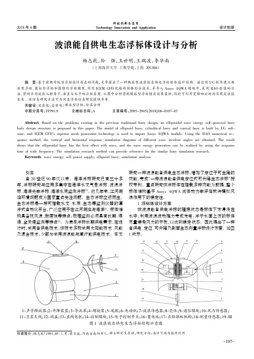
因此提出了一种自供电、定位、可升降及剖面生态测量浮标设计方案。
如图1所示。
摘要:基于前期传统型浮标设计存在的问题,文章提出了一种椭球型波浪能自供电浮标标体设计结构。
通过用UG 软件建立椭球型浮标、圆柱形浮标和圆锥形浮标模型,利用ICEM CFD 优越的网格划分技术,并导入Ansys AQWA 模块中,采用RAO 数值响应法,得到不同波浪入射角下,垂直与水平响应仿真图。
从图中分析得到椭球型浮标随波效果最好,同时可利用宽频响应时间实现波浪能发电。
该仿真研究方法可为同类浮标仿真研究提供参考。
关键词:波浪能;自供电;椭球型浮标;仿真分析中图分类号:TP391.9文献标志码:A文章编号:2095-2945(2018)06-0107-03Abstract :Based on the problems existing in the previous traditional buoy design,an ellipsoidal wave energy self-powered buoybody design structure is proposed in this paper.The model of ellipsoid buoy,cylindrical buoy and conical buoy is built by UG soft -ware,and ICEM CFD's superior mesh generation technology is used to import Ansys AQWA ing the RAO numerical re -sponse method,the vertical and horizontal response simulation diagrams of different wave incident angles are obtained.The result shows that the ellipsoidal buoy has the best effect with wave,and the wave energy generation can be realized by using the response time of wide frequency.The simulation research method can provide reference for the similar buoy simulation research.Keywords :wave energy;self power supply;ellipsoid buoy;simulation analysis作者简介:杨志乾(1991,05-),男,蒙古族,河南省南阳市人,硕士研究生在读,研究方向:海洋可再生能源利用。
波流作用下海上固定式风机基础的水动力性能数值模拟
波流作用下海上固定式风机基础的水动力性能数值模拟刘正浩;万德成【摘要】海上风机基础长期受到海流、波浪等环境荷载的交互作用,作业难度较大,研究风机基础的水动力特性可为其设计及应用提供重要参考.文中基于自主研发的船舶与海洋工程CFD求解器naoe-FOAM-SJTU,对一座固定式高桩承台风机基础在波流作用下的水动力参数进行数值模拟,研究了波浪与海流联合作用时,该风机基础在不同水深、不同波高条件下的受力、表面压力以及波面爬升现象,并与上海交通大学海洋工程国家重点实验室的模型试验结果进行比较,计算结果显示naoe-FOAM-SJTU求解器可以很好地模拟波流联合作用下风机基础的水动力特性.%Since wind turbine foundation is always under interaction of current, waves and other environmental loads,analysis of hydrodynamic performance is of great importance for its design and application.In this paper, a self-developed CFD solver named naoe-FOAM-SJTU is adopted to numerically simulate the hydrodynamic per-formance of a pile wind turbine foundation under the interaction of wave-current combinations.The forces and the flow field of the pile wind turbine foundation under different water depths and wave heights are presented and an -alyzed.The results compared with model test results show the naoe-FOAM-SJTU solver is applicable and reliable in the study of hydrodynamic performance of wind turbine foundation.【期刊名称】《江苏科技大学学报(自然科学版)》【年(卷),期】2017(031)005【总页数】7页(P555-560,566)【关键词】高桩承台风机基础;波流作用;naoe-FOAM-SJTU求解器;水动力性能【作者】刘正浩;万德成【作者单位】上海交通大学船舶海洋与建筑工程学院海洋工程国家重点实验室,上海200240;高新船舶与深海开发装备协同创新中心,上海200240;上海交通大学船舶海洋与建筑工程学院海洋工程国家重点实验室,上海200240;高新船舶与深海开发装备协同创新中心,上海200240【正文语种】中文【中图分类】O35近年来,海上风力发电逐渐成为全球风电产业发展的新方向.目前,商业化的海上风力发电场主要应用于浅水区域(水深小于30 m),并且多采用固定式基座.在海洋工程领域,高桩承台风机基础由于具有抗弯强度高、施工周期短、适应性强、成本相对较低等特点而得到广泛应用.高桩承台风机基础一般是由群桩和连接桩顶的承台组成,其所受波浪和海流载荷对风机基础的安全性及使用寿命有着重要影响,因此,研究高桩承台风机基础的水动力特性对于工程应用具有重要意义.目前,研究海上固定式风机基础水动力特性的方法主要有实地监测、模型试验、理论分析和CFD模拟等.实地监测所测得的数据比较可靠,可以作为检验依据,但其通常是针对已有风机基础,对新型风机基础的设计与应用指导意义不大.模型试验一般是在海洋工程水池中进行的,通过采用造波机、循环造流系统、水深调节等系统研究风机基础在波流作用下的水动力响应.文献[1]通过实验分析了纯波及波流共同作用时,风机基础惯性力系数和拖曳力系数的变化规律.文献[2-3]对东海大桥桩基结构的波流力进行了模型试验研究,分析了不同水深下不规则波与均匀流共同作用于小尺度单桩以及群桩的水动力特征.文献[4]针对不规则波中高桩承台进行了物理模型试验,较为系统地分析了此风机基础的群桩水动力特性,并研究了桩柱波浪力变化规律.理论分析在风机基础水动力特性研究中也有重要应用.文献[5]利用时域高阶边界元法研究了波流与结构物的相互作用问题.文献[6]基于线性势流理论和Morison公式,研究了规则波中典型桩基承台结构的波浪力计算问题,并分析了承台对桩基波浪力的影响,以及水深、桩柱相对中心距离对承台效应系数的影响.然而,随着研究不断地深入,理论分析方法受到了很大的限制,而模型试验也需要较高的成本.近年来,随着计算机技术的快速发展,CFD技术由于成本较低,并且可以得到较为详细的流场信息等优点,被广泛用于海上风力机固定式基座的水动力学性能分析.文献[7]在开源软件OpenFOAM的基础上,利用VOF(Volume of Fluid)自由面处理技术研究了破碎波和垂向的波浪载荷对固定式海上风力机基座的影响.文献[8]利用自主开发的naoe-FOAM-SJTU软件分别研究了规则波和孤立波对东海大桥风机基础的水动力特性的影响.文中采用自主开发的naoe-FOAM-SJTU求解器对一座固定式高桩承台基础在波流作用下的水动力性能进行数值模拟分析,研究波浪与海流同向工况下,该风机基础在不同水深、不同波高下的受力、流场信息及波面爬升现象,并与现有模型试验结果进行对比分析.1.1 流体控制方程对于非定常、不可压的黏性流体,采用流动的控制方程为RANS(Reynolds-averaged navier-Stokes)方程:式中:U和Ug分别为流场速度和网格节点速度;pd=p-ρg·x为流场动压力,p是总压力,ρ是流体密度;μeff=ρ(v-vt)为动力黏性系数;fσ为表面张力,只在界面处起作用,在非界面处为零;fs是数值造波中消波区的源项,仅对消波区有效.1.2 naoe-FOAM-SJTU求解器naoe-FOAM-SJTU求解器[9]是基于开源平台OpenFOAM自主开发的船舶与海洋工程CFD求解器.该求解器包含数值造波与消波模块、六自由度运动模块和动态变形网格模块等,通过求解流场和结构物六自由度运动方程,实现对船舶或者海洋工程结构物[10-15]水动力性能的有效预报.naoe-FOAM-SJTU求解器中自由面的处理采用了OpenFOAM中自带的VOF 法.在对自由面的处理过程中,需要引入体积分数α,用来表示网格内流体占有体积与整个网格体积的比重.α=0表示该网格内没有流体,0<α<1表示自由面,α=1表示该网格单元被流体充满.自由面边界的法向方向通过α函数的梯度来表示,所以网格的α函数值及其梯度值共同决定了网格单元中自由面的位置.naoe-FOAM-SJTU求解器可以实现推板造波、摇板造波、速度入口边界造波,用于处理不同的水动力问题.因为文中需要同时考虑波和流的情况,因此采用速度入口边界造波.速度入口边界造波方法通过在入口边界上设置波面位置和流体速度实现造波.由于文中研究的是浅水工况下风机基础水动力性能,浅水工况需要考虑波浪破碎、砰击等复杂非线性问题,所以一般采用高阶波浪理论,根据波浪参数之间的关系(波浪色散关系),选取斯托克斯五阶波[5]作为数值计算的波浪模型.为了避免波浪反射对计算精度的影响,需要在出口边界前设置海绵层阻尼消波区,通过在动量方程中增加一个源项fs=-ρμs(U-Ucorr),使在特定区域内的自由波面逐渐消弱至水平面,从而避免在出口边界处形成反射.文中采用的消波阻尼源项为:式中:x0为消波区的起始位置;Ls为消波区长度;αs为人工粘性系数;Ucorr为修正系数,主要进行质量修正,保证计算过程中的质量守恒.naoe-FOAM-SJTU求解器采用可以处理任意多面体结构网格的有限体积法(FVM)离散控制方程,通过调用k-ω SST、k-ε等湍流模式来封闭湍流方程;在求解过程中采用PISO算法实现速度场和压力场的耦合求解.2.1 模型及计算网格选取一座高桩承台风机基础作为研究对象,高桩承台结构主要由塔架、承台和8根桩柱组成.承台高程28 m,直径14.5 m,桩柱直径1.2 m,在承台半径R=4.3 m的圆周上均匀分布,斜度为6 ∶1.采用ProE软件进行建模,模型的缩尺比为1 ∶30,模型如图1.网格的划分是利用OpenFOAM自带的snappyHexMesh工具实现的,首先运用PointWise软件绘制背景网格,再利用snappyHexMesh工具划分平台表面的网格.计算域大小为:-5 m<x<20 m,-7.5 m<y<7.5 m,-h<z<5 m,h是水深,计算域如图2.数值水池左侧入口为入射波浪以及均匀流边界,右侧选取一段作为海绵消波区,用来抵消出口处的波浪反射,风机基础表面采用无滑移固壁条件.划分网格时对自由液面以及风机基础表面部分进行局部细化,以便精确捕捉自由液面和处理基础表面边界层内速度等物理量的剧烈变化.一个波高范围内的网格数量大于20个,边界层第一层网格厚度约为0.003 m,模型表面y+控制在50左右.整个网格量大约为200万,不同水深情况下网格数量略有变化,图3为计算整体网格、风机基础附近局部网格以及风机基础表面网格.2.2 计算工况对高桩承台风机基础模型在波流同向载荷下进行了数值模拟,计算了实际尺度为25.96、21.9和17.61 m 3种典型水深下风机基础的水动力特性,对应的模型尺度水深分别为0.991、0.856和0.713 m.还模拟了25.96 m水深下,波高分别为8.7和6.37 m时,波浪对风机基础的影响,对应的模型尺度波高为0.29和0.212 m.模型尺度水流大小均0.316 m/s.工况具体参数如表1.在分析固定式风机基础在波流联合作用下的水动力性能时,除了分析风机基础整体受力外,还需要对风机基础上危险点位置的表面压力进行探测,物理实验和数值模拟都在风机基础模型表面设置了15个压力测试点,这些压力探测点都相对固定在风机基础上,其位置如图4.3.1 数值计算结果验证为验证数值模拟的可靠性,首先选取典型工况的数值模拟结果与模型试验结果进行比较.图5为工况5(即水深0.991 m,流速0.316 m/s,波高0.29 m)下风机基础x方向受力以及典型位置压力测试点的数值模拟与模型试验结果的对比.从图中可以看出,高桩承台风机基础在x方向受力及局部压力测试点的计算结果与实验结果吻合较好,文中CFD方法预报的x方向受力最大值与模型试验结果一致,从图中还可以看出,模型试验在受力最小值附近出现了小峰值,文中CFD方法也预报出了这个峰值变化.从图5(b)~(d)中可以看出,对于典型位置压力的探测,计算结果与模型试验结果也可以很好地吻合,这说明文中CFD方法可以很好地预报风机基础各位置的砰击压力.图6为波峰时刻风机基础周围波面情况的数值模拟及模型试验结果.从图中可以看出,文中CFD方法可以很好地模拟波流作用下风机基础周围自由液面变化情况,此刻,数值模拟的风机基础周围的波浪爬高的最大位置与模型试验的波浪爬高最大位置是相近的.由于风机基础对波浪的反射作用,波浪发生了明显的破碎现象,通过与模型试验的对比,可以看到,文中CFD方法可以较为精确地捕捉波浪破碎现象,同时可以准确地预报波浪爬升的最大位置.这也验证了计算结果的可靠性与准确性.3.2 水深对高桩承台水动力特性的影响高桩承台风机基础受力在结构分析中十分重要,基础主要受海流载荷与波浪载荷的力.图7(a)为高桩承台风机基础在不同水深下的受力情况的时历曲线.从图中可以看出,不同水深条件下风机基础所受到的x方向的正向力差别很小,因此,在浅水条件下,水深对风机基础的正向受力影响并不大,但是风机基础在x方向负向受力差别较大,且水深越深,风机基础所受到的负向力越大.由于浅水效应的影响,3种水深条件下,风机基础在x方向所受的正向力都比负向力大得多.当水深为0.991 m时,风机基础在x方向所受的力在波峰处的最大值是波谷处的最小值绝对值的3.6倍左右.上文提到,在进行数值计算时,风机基础表面布置了15个压力探测点.图7(b)~(d)展示了不同水深条件下,3个典型位置(P1、P3、P11)的压力探测点的砰击压力情况.从图中可以看出,不同位置的压力探测点都受到了周期性的脉冲压力,并且不同位置的压力值也不相同,测压点的压力由下而上逐渐减小.对于最高位置的P3压力探测点,可以发现,在3种水深条件下都出现了周期性压力为零的情况,说明期间P3压力探测点在水面以上,并且水深越浅,P3压力探测点在水面以上的时间越长.从P1、P3、P11 3个压力探测点的砰击压力时历曲线还可以看出,水深越深,压力探测点的砰击压力越大.3.3 波高对高桩承台水动力特性的影响图8(a)为水深0.991 m时,不同波高条件下风机基础的受力情况.从图中可以看出,波高的改变对风机基础受到的x方向的正向力影响较大,波高较大的入射波对风机基础的所受正向力也更大.从图中还可以看出,波高的改变对风机基础受到的x方向的负向力影响并不大,这两个波高条件下,x方向的负向力几乎相等.图8(b)~(d)为不同波高条件下,3个典型位置(P1、P3、P11)压力探测点的砰击压力情况.不同位置的压力探测点都受到了周期性的脉冲压力,波高越大,压力探测点所受的砰击压力越大.3.4 波浪爬高与表面压力图9、10分别为波高为0.29 m和0.212 m条件下,一个波浪周期内4个不同时刻风机基础表面压力及自由面图.从图中可以观察到在两个波高条件下,风机基础都发生了上浪现象,并且波高越大,上浪现象越明显.由于风机基础对波浪存在反射作用,在图9、10中均可以观察到明显的波浪破碎现象,并且波高越大,波浪破碎现象越严重,这也说明,波高越大,风机基础对波浪的反射作用越明显.从图中还可以看到,某些时刻承台会在水面之上,此时P3压力探测点测得的压力为零,这与图7中观察的结果一致.从图9、10中还可以观察到一个周期内不同时刻风机基础表面压力变化情况.从图中可以看出,在一个周期内,风机基础表面压力与其被水淹没状态有关,当波峰到达风机基础表面时,风机基础的表面压力最大,当水脱离承台时,风机基础会受到一个负冲击压力的作用.文中基于自主开发的船舶与海洋工程CFD求解器naoe-FOAM-SJTU,数值模拟了一座固定式高桩承台风机基础在波流作用下的水动力特性.首先将典型工况的数值模拟结果与模型试验结果进行了对比分析,可以发现文中数值模拟采用的naoe-FOAM-SJTU求解器能有效地模拟高桩承台风机基础在波流作用下的载荷情况,并可以精确地捕捉风机基础周围的波浪爬升、破碎以及周围流场信息.其次,在波浪与海流同向的条件下,研究了该风机基础在0.991、0.856和0.713 m 3种典型水深条件下的受力和流场信息等,研究发现,3种水深对该风机基础水平方向的受力影响不大,但是对砰击压力的影响很大,水深越深,风机基础受到的砰击压力越大.通过研究同一水深,不同波高条件下风机基础的受力、表面压力等,可以发现,波高的改变对风机基础的受力等影响都很大,并且波高越大,观察到的波浪破碎现象越严重,这也说明,波高越大,风机基础对波浪的反射作用越明显.文中计算结果展示了naoe-FOAM-SJTU求解器可以很好地模拟波流联合作用下风机基础的水动力特性,并提供一些有工程应用参考价值的分析结论.*通信作者:万德成(1967—), 男, 教授, 研究方向为船舶水动力学.E-mail:**************.cn【相关文献】[ 1 ] VENUGOPAL V, VARYANI K S, WESTLAKE P C. Drag and inertia coefficients for horizontally submerged rectangular cylinders in waves and currents[J]. Proceedings of the Institution of Mechanical Engineers, Part M: Journal of Engineering for the MaritimeEnvironment, 2008, 223(1): 121-136. DOI:10.1243/14750902jeme124.[ 2 ] 兰雅梅, 薛雷平, 刘桦, 等. 东海大桥桥梁桩柱承台水动力模型试验研究——第一部分:作用于单个小尺度桩柱上的波流力[J]. 水动力学研究与进展:A辑, 2004, 19(6): 753-758.DOI:10.3969/j.issn.1000-4874.2004.06.009.LAN Yamei, XUE Leiping, LIU Hua, et al. Experimental studies on hydrodynamic loads on piles and slab of Donghai Bridge part I: hydrodynamic forces on a single pile in wave-current combinations[J]. Journal of Hydrodynamics:A,2004, 19(6): 753-758.DOI:10.3969/j.issn.1000-4874.2004.06.009.(in Chinese)[ 3 ] 兰雅梅, 刘桦, 皇甫熹, 等. 东海大桥桥梁桩柱承台水动力模型试验研究——第二部分:作用于群桩及承台上的波流力[J]. 水动力学研究与进展:A辑, 2005, 20(3): 332-339.DOI:10.3969/j.issn.1000-4874.2005.03.009.LAN Yamei, LIU Hua, HUANG Fuxi, et al. Experimental studies on hydrodynamic loads on piles and slab of Donghai Bridge-Part II: HYdrodynamic forces on pile array and slab in wave-current combinations[J]. Journal of Hydrodynamics:A,2005, 20(3): 332-339. DOI:10.3969/j.issn.1000-4874.2005.03.009.(in Chinese)[ 4 ] 雷欣欣, 孙大鹏, 徐雪蛟, 等. 作用在高桩承台上的不规则波波浪力试验研究[J]. 水道港口, 2013, 34(4): 277-284. DOI:10.3969/j.issn.1005-8443.2013.04.001.LEI Xinxin, SUN Dapeng, XU Xuejiao, et al. Experimental study of irregular wave force loads on high rise pile platform[J]. Journal of Waterway and Harbor, 2013, 34(4): 277-284. DOI:10.3969/j.issn.1005-8443.2013.04.001.(in Chinese)[ 5 ] 刘珍, 滕斌, 宁德志, 等. 波流与结构物相互作用的数值模拟[J]. 计算力学学报, 2010, 27(1): 82-87.LIU Zhen, TENG Bin, NING Dezhi, et al. Time-domain simulation of the wave-current action on 3D bodies[J]. Chinese Journal of Computational Mechanics, 2010, 27(1): 82-87.(in Chinese)[ 6 ] 姚文伟, 刘桦. 规则波中圆形承台对桩基波浪力的影响[J]. 力学季刊, 2009, 30(3): 357-362. YAO Wenwei, LIU Hua. Effect of circular slab for wave loads on piles in regular waves[J]. Chinese Quarterly of Mechanics, 2009, 30(3): 357-362. (in Chinese)[ 7 ] BREDMOSE H, JACOBSEN N G. Breaking wave impacts on offshore wind turbine foundations: focused wave groups and CFD[J]. 29th International Conference on Ocean, Offshore and Arctic Engineering: Volume 3, 2010. DOI:10.1115/omae2010-20368.[ 8 ] ZHOU H, CAO H J, WAN D C. Numerical predictions of wave impacts on the supporting structures of Shanghai Donghai-Bridge offsho re wind turbines[C]∥In The Twenty-third International Offshore and Polar Engineering Conference, Anchorage, 2013-6.30~7.05. International Society of Offshore and Polar Engineers, 2013: 216-224.[ 9 ] SHEN Z R, WAN D C. An irregular wave generating approach based on naoe-FOAM-SJTU solver[J]. China Ocean Engineering,2016,30(2):177-192.DOI:10.1007/s 13344-016-0010-1.[10] SHEN Z R, WAN D C. An irregular wave generating approach based on naoe-FOAM-SJTU solver[J]. China Ocean Engineering, 2016, 30(2): 177-192. DOI:10.1007/s13344-016-0010-1.[11] LIU Y, XIAO Q, INCECIK A, et al. Investigation of the effects of platform motion on the aerodynamics of a floating offshore wind turbine[J]. Journal of Hydrodynamics, Ser B, 2016, 28(1): 95-101. DOI:10.1016/s1001-6058(16)60611-x.[12] CAO H J, WAN D C. RANS-VOF solver for solitary wave run-up on a circular cylinder[J]. China Ocean Engineering, 2015, 29(2): 183-196. DOI:10.1007/s13344-015-0014-2.[13] SHEN Z, WAN D, CARRICA P M. Dynamic overset grids in OpenFOAM with application to KCS self-propulsion and maneuvering[J]. Ocean Engineering, 2015, 108: 287-306. DOI:10.1016/j.oceaneng.2015.07.035.[14] 王建华, 万德成. 南海浮式码头与系泊系统动力耦合分析[J]. 水动力学研究与进展: A辑, 2015, 30(2): 180-186.WANG Jianhua, WAN Decheng. Dynamic coupling analysis of the mooring system and floating pier in the South China Sea[J]. Journal of Hydrodynamics, A, 2015, 30(2): 180-186. (in Chinese)[15] SHEN Z R, YE H X, WAN D C. URANS simulations of ship motion responses in long-crest irregular waves[J]. Journal of Hydrodynamics;A, 2014, 26(3): 436-446.DOI:10.1016/s1001-6058(14)60050-0.。
水下滑翔器动力学建模及优化设计_英文_
第14卷第3期船舶力学Vol.14No.3 2010年3月Journal of Ship Mechanics Mar.2010 Article ID:1007-7294(2010)03-0228-09Dynamic Modeling and Optimization Designon Underwater GlidersZHANG Hong-wei1,WANG Yan-hui1,CHEN Chao-ying1,ZHU Guang-wen2 (1Tianjin University,Tianjin300072,China;2National Ocean Technology Center,Tianjin300111,China)Abstract:Underwater gliders are new floatation devices that are used extensively for oceanographic analysis.The vertical motion of underwater gliders is determined by the gliders’buoyancy to gravity specific ratio.The horizontal motion is controlled by the fixed horizontal wings and the relative posi-tion of gravity and buoyancy center.In this paper,the dynamics and design of underwater gliders are studied using Gibbs function and Appell equations.In the first step of the analysis,general equations that define the relationship between the moving mass in the glider and the glider’s dynamics are obtained.Next,Computational Fluid Dynamics(CFD)software FLUENT is used to obtain the glider’s hydrodynamic parameters for dynamic modeling.Since the position of the wings is one of the most important design parameters,a better optimal position is determined in order to minimize the power consumption.Finally,simulation and experimentation are used to validate the proposed model.Key words:underwater glider;dynamic modeling;Gibbs function;Appell equation;CFDCLC number:U674.941Document code:A1IntroductionIn recent years,underwater gliders have received increased attention from both academia and industry.The concept for conventional underwater gliders is derived from autonomous un-derwater floats which were first proposed by Henry Stommel in1989[1].The first prototype of the underwater glider was designed by Webb Research Corp.in the U.S.A.in1995[2].Since their introduction,underwater gliders have been used extensively for oceanographic sensing and data collection.They have special buoyancy devices that make them attractive for these applications.The buoyancy devices alternately reduce and expand the volume of water dis-placed by the glider,thereby controlling the dive and climb of the glider through the water.The resulting motion of the glider is a saw-toothed pattern.By controlling these devices,the glider can be made to follow programmed trajectories.Additional advantages of underwater gliders in-clude their low cost,low power consumption,autonomy,and capability for long-range sorties.The United States[2-4],Japan[5],France[6-7],New Zealand[8],Canada[9]and Australia[10]all carriedReceived date:2009-05-20Foundation item:Supported by the National Natural Science Foundation of China(50705063,50835006);National Natural Science Foundation of Tianjin(09JCZDJC23400)Biography:ZHANG Hong-wei(1976-),male,lecturer of Tianjin University;WANG Yan-hui(1979-),male,associate professor,Tianjin University,E-mail:yanhuiwang@.out the study of underwater gliders.Nowadays there are three typical kinds of underwater gliders:Slocum,Spray and Seaglider.They are all developed by the United States.China began un -derwater gliders ’researches at the beginning of this century.Tianjin University,National Ocean Technology Center,Shenyang Institute of Automation,Zhejing University,China Ship Scientific Research Center and Northwest Polytechnical University are all doing the research of underwater gliders and some theories and technologies are published [11-15].Tianjin University,cooperating with National Ocean Technology Center,developed an ex -perimental prototype of underwater glider propelled by temperature difference energy in 2005.The underwater glider contains pressure hull,pose control setups,fixed wings,controller and communication module,buoyancy changing module by temperature difference energy and sensor module.The underwater glider is 52kg in air and has a buoyancy adjusting capability of 350ml.The cruise speed is 0.5kns.Working depth is up to 100m.The glider makes the buoyan -cy changing be reality using a special hydraulic system which can absorb temperature differ -ence energy.2Modeling of glidersFig.1is the sketch of an underwaterglider.It shows the main factors of the glider,consisting of a pressure hull,two fixed ex -ternal wings and tails and moving internalmasses.The pressure hull is considered asthe rigid base body that can translate and/or rotate in the fluid field.2.1KinematicsThe inertial frame and the coordinateframe attached to the glider ’s body areshown in Fig.1.The main external forces and moments acting on the glider are the hydro -dynamic forces and moments caused by the glider ’s motion in the water.Buoyancy and gravitational forces are two other external forces that act on the glider.Internal actuators are used to control its attitude.An underwater glider is in its neutral state when buoyancy and gravitational forces balance.It has two bladders.One is an internal reservoir that is sealed in the pressure hull and the other is an external bladder that is flushed.When the external bladder deflates,the glider sinks because the gravity of the under -water glider remains constant while the buoyancy decreases.Conversely,the glider ascends when the external bladder inflates.In this paper,the ballast mass is used to represent this buoyant 1.Pressure hull;2.Eccentric rotating mass;3.Tra-nslational mass;4.Offset mass;5.Ballast mass Fig.1Sketch of the underwater glider 第3期ZHANG Hong-wei et al:Dynamic Modeling and Optimization (229)The pose of the glider is defined as follows:The B -e 1e 2e 3coordinate frame is first superposed with the E -εηξcoordinate frame.Then the glider is made to rotate about the e 1,e 2,and e 3axes with the angles φ,θ,and ψrespectively.We select ε,η,ξ,φ,θ,ψ,δ,and r m 1as generalized coordinates and define S 01as the rotation matrix that describes the transformation from body coordinates to inertial coordinates.Thus the angular velocity of the glider ’s hull can be expressed in inertial coordinates as:ωh =10sin θ0cos φ-sin φcos θ0sin φcos φcos 觶觶觶觶觶觶觶觶θφ觶θ觶ψ觶觶觶觶觶觶觶觶觶觶觶觶觶觶觶觶觶觶觶觶觶T εη觶觶觶觶觶觶觶觶觶觶ξ(1)The positions of the rigid bodies are expressed in inertial coordinates.These position vec -tors are differentiated with respect to time in order to obtain velocities.The acceleration of the bodies is found by differentiating the velocity with respect to time.2.2DynamicsThe Gibbs function of the glider system is expressed as follows:system.As a result of the hydrodynamic forces acting on the fixed horizontal wings,this alternating movement is converted into glide.When it works,the glider will have a saw-toothed trajectory in the vertical plane.The translational mass,which moves along the e 1axis,controls the glid -er ’s pitch.The eccentric turn along the e 1axis of the rotating mass gives the glider a rolling motion which causes the glider turn to left or right.The definition of the variables is shown in Name Variable description αm bm mm om rm hm sr Br br mr or rr sa ha rD f Angle of attack Ballast mass Translational mass Offset mass Eccentric rotating mass Pressure hull and wings m b +m o +m h Position vector fromE to B Position vector from B to m b Position vector from B to m m Position vector from B to m o Position vector from B to m r Position vector from the center of gravity to the center of buoyancy Hull acceleration Acceleration of the rotating mass Added mass cross term U m a m v h v r v m αh αr αm ωh ωr ωm δXYZ M i B i M fI f Force from hull to the translational mass Translational mass acceleration Hull velocity Rotating mass velocity Translational mass velocity Hull angualr acceleration Angular acceleration of the roating mass Translational mass angular acceleration Hull angular velocity Rotating mass angular velocity Movable mass angular velocity Angle of rotation of the rotating mass Components of hydrodynamic forces The ith component of hydrodynamic moments The buoyant force of the body Added mass matrix Added inertia matrixVariable description Tab.1Definition of variables230船舶力学第14卷第3期GT =Gs+Gr+Gm+Gf=12ahαhωharαrωram77777777777777777777777777Tg11g12g13g14g15g16g17g21g22g23g24g25g26g27g31g32g33g34g35g36g37g41g42g43g44g45g46g47g51g52g53g54g55g56g57g61g62g63g64g65g66g67g71g72g73g74g75g76g7777777777777777777777777777ahαhωharαrωram77777777777777777777777777(2)when Gs ,Gr,Gmand Gfrepresent the Gibbs functions of the bodies respectively.The elementsof the matrix are defined as follows:g 11=msI+Mf,g12=-msr軇h+D Tf,g13=-m s I+M f軇軇ω軗hr軇s,g21=msr軇h+Dfg 22=S10JsS T10+S10JmS T10+S10JfS T10,g23=-ω軗ThS10Js+Jf軗軗S T10-ω軗TrS10JmS T10g 31=-m s I+M f軇軗r軇hω軗h,g32=-S10Js+Jf軇軗T S T10ω軗h-S10JmTS T10ω軗h,g44=mrIg 55=S10JrS T10,g56=-ω軗TrS10JrS T10,g65=-S10J TrS T10ω軗r,g77=mmIwhile all the other values of gi j=0i,j=1…7.Using Appel equations,the following can be obtained:坠GT 坠q咬i =QTi,i=1…8(3)where q咬i are the mean generalized coordinates and QTiare the mean generalized forces.Because the glider is a holonomic dynamic system,the generalized force is:QTi =7j=1ΣF j·坠r j坠qi+Mi,i=1 (8)where Fj is the force on the jth body shown in Fig.2,and Miis the moment according to theith generalized coordinate.2.3Simplification of the dynamic modelThe running characteristics of underwater gliders in the vertical plane are important to the design and analysis of the glider.When the motion of the glider is restricted to the vertical plane,the dynamic equations of the glider can be simplified as follows:the pressure hull of the glider is considered as uniform,so that the hull mass is distributed and the center of buoyancy is the same to the center of gravity;the offset mass is negligible;the rotating mass is resting when the glider is restricted to move in vertical plane.From the above simplifications,it can beobserved thatφ=ψ=η=rm2=rm3=rr2=δ=0.Thus,S 01=cosθ0sinθ010-sinθ0cos7777777777θ第3期ZHANG Hong-wei et al:Dynamic Modeling and Optimization (231)Because of the symmetrical shape of the underwater glider,the added mass can be ex-pressed as follows[16]:Mf =mf11000mf2200mf334444444444Df=ΟIf=If11000If2200If334444444444,Substituting these parameters into equations(2)and(3)gives the dynamic equations of the glider in vertical planeI 11I12I13I14I 21I22I23I24I 31I32I33I34I 41I42I43I444 4 4 4 4 4 44444444ε咬ξ咬θ咬r咬m1444444444444444444=F1F2F3F444444444444444(4)whereI 11=mrr cosθ-mrrr1sinθ-mmrm1sinθ,I12=-mrr sinθ-mrrr1cosθ-mmrm1cosθ,I 13=J22+mrrr12+mrr2+mmrm12,I21=mh11+mm+mr,I23=mrr cosθ-mrrr1sinθ-mmrm1sinθ,I 24=mmcosθ,I32=mh33+mm+mr,I33=-mrr sinθ-mrrr1cosθ-mmrm1cosθ,I 34=-mmsinθ,I41=mmcosθ,I42=-mmsinθ,I44=mm,F 1=Mw2-Brb1cosθ-mmgrm1cosθ-mrgrr1cosθ-mrgr sinθ-2mmrm1r觶m1θ觶,F 2=D cosθ-··α+L sinθ-··α+2mmsinθr觶m1θ觶+m r r r1cosθ+m m r m1cosθ+m r r sin··θθ觶2,F 3=-L cosθ-··α+D sinθ-··α+m s+m m+m r··g+B+Bh+2mmcosθr觶m1θ觶-m m r m1sinθ-m r r cosθ+m r r r1sin··θθ觶2,F 4=um-mmg sinθ+mmrm1θ觶2,others Iij=0i,j=1 (4)2.4Hydrodynamic forces and momentsIn this section,the hydrodynamic forces and moments in E-εξplane are derived.The aerodynamic drag(D),lift(L)and moment(M)of the underwater glider in the vertical plane can be calculated using the following equations[17]:D=KD0+KD·α2··v2(5)L=KL0+KL·α··v2(6)M2=K M0+K M···αv2+Kθ1·θ觶+Kθ2·θ觶2(7)In equations(5),(6)and(7),parameters KD0,KD,KL0,KL,KM0,KM,Kθ1,Kθ2are aerody-namic coefficients and can be identified by tank experiments or CFD analysis.The software,FLU-ENT,is used to perform the CFD analysis of the underwater glider.The use of virtual experi-232船舶力学第14卷第3期ments saves the cost of physical experiments and is convenient for varying the parameters of the glider.The fixed horizontal wings are symmetrical slats which are suitable for the low velocity of the glider.The position of the wings relative to the hull is important to the gliding capability. In order to obtain a better design,three virtual designs with varying wing positions are pre-sented.The three designs are shown in Fig.2.(a)Wings are placed0.3meters fore the CB;(b)Wings are placed at CB;(c)Wings are placed0.3meters aft the CBFig.2Three virtual designs of the underwater gliderThe following steps are used to calculate the aerodynamic coefficients for each of the design models.Firstly,with the velocity fixed at0.3m/s and the angular velocity set to zero,the drag,lift and moment are calculated for angles of attack ranging from-5°to5°.The step size in the angles is1°.Thus we get11drags,lifts and moments at the different angles of attack respectively.Then,using the Least-Squares Method and equations(5),(6),and(7),all theparameters,with the exception of Kθ1and Kθ2can be identified.The moving nets method,whichis a part of the FLUENT software,can be used to identify Kθ1and Kθ2by putting KM0and KMin equation(7)and using varying values for the angular velocities.Tab.2shows the values of the aerodynamic coefficients for the three different designs.Tab.2Parameter values for the three glidersKD0KDKL0KLKM0KMKθ1Kθ2a b c 2.202.202.2025252513013013098-98-29529-30530According to Ref.[17],we choose the added mass as follows:Mf =5000650007!"""#$%%%&5Df=ΟIf=4000120001!"""#$%%%&13Design for fixed wings’positionOceanographic gliders are designed for long ranges and typically have very low power consumption.Additionally,oceanographic sensors are placed on gliders in order to keep gliders within the working range during glider missions.The positions of the glider’s external wings 第3期ZHANG Hong-wei et al:Dynamic Modeling and Optimization (233)have a significant influence on the dynamic behavior of underwater gliders.This in turn influ-ences the power consumption and sensor states.In order to improve the horizontal velocity,the steady pitch angle of this glider is set to±38°[11],and because of the glider’s structure,the position vectors are set to rr1=0.3m,rr3=0.05m,rb1=-0.7m.When the position of the origin of the translational mass is-0.3m,the ballastmass has a buoyancy of±0.05kg.The mass of each body in the glider’s design is:mh=40kg,mm =5kg,mr=5kg.Equation(4)is then used to analyze the performances of the three gliders.(a)Fixed wings are placed0.3m before the CB and the movable mass moved0.054m aft to geta pitch angle of38°;(b)Fixed wings are placed at the CB and the movable mass moved0.046maft to get a pitch angle of38°;(c)Fixed wings are placed0.3m aft the CB and the movable mass moved0.039m aft to get a pitch angle of38°Fig.3Dynamic responses of three glidersFrom Fig.3(c),it can be clearly observed that this glider requires only0.039m’s movementof the translational mass to get a desired pitch angle while the gliders shown in Fig.3(a)and(b) require0.054m and0.046m,respectively.Since servos are used to change the position of the movable mass and since the gliders require frequent inflections between downwards and up-wards,the glider in(c)is superior to the others in terms of saving energy.It can also be ob-served that glider(a)has a large overshoot.The pitch angle of this glider before steady state gliding is more than60°.Since a compass with a measuring range of±60°is used to measure the pitch angle,glider(a)is out of the range of the compass.The greater number of oscillations of glider(b)before steady state is achieved affects the measurements obtained form the sensors. As a result,glider(c)is selected for the final design.The time needed for glider(c)to attain a steady gliding state is determined to be about50s longer than the time required for the other two gliders.These50s can be considered as negligible because the glider operates in open wa-ters and always runs at a low velocity.4Trajectory simulation and experimentsGenerally,the glider travels in a saw-tooth trajectory while following programmed trajecto-ries.Fig.4shows the simulation results of glider’s trajectory in the E-εξplane and also the ex-perimental data.The cycle time of the underwater glider moving in the vertical plane is around 400s.The pitch angle of it is near40°.According to the depth of the experiment lake,a trial depth of32m is selected.It can be seen from Fig.4(c)that the experimental data matches well 234船舶力学第14卷第3期第3期ZHANG Hong-wei et al:Dynamic Modeling and Optimization (235)to the simulation results.(a)Position of the translational mass(b)Pitch angle of the glider(c)Comparison of the simulation and the experiment saw-tooth trajectoryFig.4The simulation results of the glider in the vertical plane5ConclusionsUnderwater gliders have the potential to be used in an enormous number of oceano-graphic applications.The dynamic model of the glider developed in this paper along with the analysis conducted for the simpler model provides significant insight into the dynamic behav-iors of gliders.The glider’s dynamic model presented here is general and not vehicle specific. Therefore,it can be applied to the design and optimization of gliders in general.The good cor-relation between the simulation and lake trial proves the validity of the proposed model.This work complements the other research that is being conducted on the design and dynamic analysis of underwater gliders.References[1]Stommel S.The Slocum mission[J].Oceanography,1989,2(1):22-25.[2]Webb D,Simonetti P,Jones C.SLOCUM:An underwater glider propelled by environmental energy[J].IEEE Journal ofOceanic Engineering,2001,26(4):447-452.[3]Eriksen C C,Osse T J,Light R D,et al.Seaglider:A long-range autonomous underwater vehicle for oceanographic re-search[J].IEEE Journal of Oceanic Engineering,2001,26(4):424-436.[4]Sherman J,Davis R E,Owens W B,et al.The autonomous underwater glider“Spray”[J].IEEE Journal of Oceanic Engi-neering,2001,26(4):437-446.236船舶力学第14卷第3期[5]Tomoda Y,Kawaguchi K,Ura T,et al.Development and sea trials of a shuttle type auv ALBAC[C]//8th Int.Symposiumon Unmanned Untethered Submersible Tech.Durham,NH,1993:7-13.[6]Moitie R,Seube N.Guidance and control of an autonomous underwater glider[C]//12th Int.Symposium on UnmannedUntethered Submersible Tech.Durham,NH,2001.[7]Ahmed-ali T,Cuillerier L,Seube N.Nonlinear identifier and observer design for an underwater glider[C]//IFAC Conf.onManeuvering and Control of Marine Crafts.Girona,Spain,2003.[8]Underwater deep ocean glider[EB/OL].accessed May2008,online available at:/px/research/electronics/current-research-projects/underwater-deep-ocean-glider.[9]GSC Pacific(Sidney)-Ocean gliders in Canada[EB/OL].accessed May2008,online available at:http://gsc.nrcan.gc.ca/org/sidney/index_e.php.[10]Facilities-Integrated marine observing system[EB/OL].accessed May2008,online available at:.au/facilities/ocean-gliders.html.[11]Wang Y,Wang S,Xie C.Dynamic analysis and system design on underwater glider propelled by temperature differenceenergy[J].Journal of Tianjin University,2007,40(2):133-138.(in Chinese)[12]Ma Z,Zhang H,Zhang N,et al.Study on energy and hydrodynamic performance of the underwater glider[J].Journal ofShip Mechanics,2006,10(3):64-69.[13]Wang C,Yu J,Wu H,et al.Research on movement mechanism simulation and experiment of underwater glider[J].OceanEngineering,2007,25(1):64-69.(in Chinese)[14]Ge H,Xu D,Zhou Q.Dynamic modeling of a low speed underwater vehicle based on moving mass control[J].MechanicalScience and Technology,2007,26(3):327-331.(in Chinese)[15]Kan L,Zhang Y,Fan H,et al.Buoyancy driven underwater glider motion simulation[J].Computer Engineering and Ap-plication,2007,43(18):199-201.(in Chinese)[16]Graver J.Underwater gliders:dynamics,control and design[D].Princeton University,2005.[17]Leonard N,Graver J.Model-based feedback control of autonomous underwater gliders[J].IEEE Journal of Oceanic Engi-neering,2001,26(4):633-645.水下滑翔器动力学建模及优化设计张宏伟1,王延辉1,陈超英1,朱光文2(1天津大学机械工程学院,天津300072;2国家海洋技术中心,天津300111)摘要:水下滑翔器是广泛应用于海洋观测的新型浮力驱动设备。
应用TELEMAC模型系统的洱海二维水动力模型研究
2D Hydrodynamic Modelling for ErhaiLake Applying TELEMAC ModellingSystem1Cheng* Claude GUILBAUDZHANGSchool of Ocean LHFHohai University Sogreah ConsultantsNanjing, P. R. China 210098 Echirolles, France 38130baily_zc@ claude.guilbaud@sogreah.frTONG ChaofengState Key Laboratory of Hydrology-Water Resources and Hydaulic EngineeringHohai UniversityNanjing, P.R.China 210098tongchaofeng@AbstractNumerical modelling is being used extensively to assist decision making in hydraulicand environmental field. TELEMAC System is a numerical modelling system for freesurface hydrodynamics, water quality and sedimentology etc, popular in Europe butnot introduced in China. The construction of 2D hydrodynamic model for Erhai Lakeapplies TELEMAC System for an interesting and important study. From the modeledresults, lake hydrodynamics are well reproduced, the tracer’s behavior can also beseen. For the modelling itself, TELEMAC shows a good convenience and capabilityof reproducing reality.Keywords: numerical modelling, FEM model, TELEMAC System, Erhai Lake1IntroductionErhai Lake lies in the middle of Dali Prefecture, Yunnan Province, southwest China. The position is 25°16'~25°25'N, 99°32'~100°27'E. In terms of hydrology it is in the upriver part of the Lancang-Mekong River Basin which extends across 6 countries in the Southeast Asia. The Erhai Lake Basin extends across over 16 towns of Dali City and Eryuan County with a total area of 2565 square km, which accounts for 8.7% of the area of whole Prefecture. While the whole Erhai Lake surface lies in Dali city, which is the capital and political, economic and cultural centre of the Dali Prefecture. Erhai Lake is the core area of the Erhai National Nature Reserve and national touristy area. Also it supplies the prefecture with its volume for industrial and domestic usage, the diversity of aquatic animals and plants. [1]- [2]Erhai Lake is the 7th biggest freshwater lake in China. It has a surface area around 250 square km. The length of the lake from south to north is about 42.5 km, while the distance from the west to east is much shorter, about 6 km in average (min. 3 km; max. 9 km). The shape of the lake surface looks like an ear, and this was how it got its name “Erhai” (in Chinese, “Er” means “ear” and “hai” means “sea”).1 Supported by FASEP and Erasmus Mundus-1--2-As a component of the Yunnan Urban Environment Project, water environment assessment of the Erhai Lake plays a key issue in the REA of Erhai Lake Basin since all the influences caused by the new projects will show their final impact on the Erhai Lake water body. Thus the numerical model should enable reproducing lake hydrodynamics and then the water quality. As it is the first time that numerical modelling is applied in Erhai Lake and an initial application of TELEMAC System in China, it is clear that much effort would be made on the establishment of the model.2 Data reorganization and analysisTo the west of Erhai lies the mountain Cangshan, which has a width from west to east about 10 km and length from south to north about 55 km. The Peak Malong is the summit which reaches at 4112 m in elevation. To the east of Erhai, it is the Yungui Plateau whose elevation is around 2000 m.Three islands lie in the lake: Jinsuo Island in the southeast, Nanzhao Island in the northeast and Little Putuo Island in the middle of the east coast. They are recently developed into popular touristy sites. The total area of the islands is about 0.75 square km, which counts 0.308% of the area of Erhai.Figure 1: River systems in Erhai Lake Basin Figure 2: Erhai Lake satellite image in 2002There are 117 identified river reaches in the lake basin, including the famous “Cangshan 18 streams”. The average annual inflow volume is about 825 Million cubic meters. Miju River, Yong'an River, Luoshi River and Boluo River are the four main inflows, accounting for over 70% of the total water received by Lake Erhai. Among them, Miju River, which is the genuine source of the Erhai Lake, has an average annual inflow volume of 510 Million cubic meters, which takes about 60% of the total annual inflow volume of the lake.The only natural river outflow of Erhai Lake is Xier River, which lies in the southwest of Erhai Lake. It then flows 22km to join Yangbi River in the downstream, and finally inpour into the Lancang-Mekong River. Since 1973, a dam with control gates has been built mostly for electricity generation and watervolume control on the Xier River, which later on has taken the key impact on controlling the whole lake area.On the east coast near Jinsuo Island, a pumping station was built in 1994 to for water diversion to Binchuan County, which lies out of the Mekong River Basin, but within Dali Prefecture. The project is called “Erhai-Binchuan Water Diversion”. The designed discharge is 10m3/s, and designed annual average outflow volume is 50 million cubic meters.The whole surface water outflow is now controlled by Dali Erhai Management Bureau.Before 2003, the main purpose of the control of Erhai is electricity generation, but then it had been changed into environmental protection and sustainable development. The mechanism on controlling the gate had changed a lot. Thus we consider the discharge in recent years more important.The volume of ground water resource in Erhai Lake area amounts to 380 million m3. But the impact of ground water movement is not clear enough to be taken into account.When the surface elevation is 1965.35m (Chinese national elevation system-1985), the average depth of Erhai Lake is about 10.12m, while maximum depth is 20.7m, and the volume of the lake is about 2560 Million cubic meters which also varies with the water level of the lake. The average bottom slope angle is 23 degree.Since the dam had been built, the water level in Erhai Lake has been somewhat under a great influence of human activities as well as the natural phenomenon such as rainfall-runoff, evaporation and transpiration. Several standards had been established since 1984 concerning the management of the lake water level.From year 1984 to May 31st 2004, the minimum water level has been set to 1962.69m, and maximum set to 1965.69m, a variation of 3m water level change was allowed. Since June 1st 2004, new standard has been set, the minimum required level rose to 1964.3m, maximum level rose to 1966m, but the extend of water level variation has been reduced to 1.7m mainly for the habitat protection.Notably the elevation is in Haiphong elevation coordination system, which has been widely used in Yunnan Province. The datum plane of Haiphong system is 8.31m lower than the one of the Chinese National elevation coordination system.Due to the valley of the Xier River in the southwest of Erhai Lake, the wind direction in Xiaguan Town (southwest part) appears SW with frequency 32%. Annual average wind speed is 2.4 m/s in Dali Town (east coast) and 4.1m/s in Xiaguan (southwest). Maximum wind speed in Dali Town is 40 m/s W, 20 m/s WSW in Xiaguan. The windiest month is February.3Introduction of the TELEMAC Modelling SystemThe TELEMAC system is a set of programs based on numerical resolution of finite element method (FEM) and designed for the open channel flows using a string of common processes (digitization and graphics). It is developed by LNHE (Laboratoire National d’Hydraulique et Environnement) - Research department of EDF. It was decided to use finite elements technique for numerical modelling in the 1980s, and the first version TELEMAC-2D was born in 1987. New versions have been developed and released continuously since then. Now it is an integrated modelling system which contains two and three dimension modules for the study of hydrodynamic currents, waves, sedimentation, groundwater flows and water quality. [3]The TELEMAC-2D code solves depth-averaged free surface flow equations as derived first by Barré de Saint-Venant in 1871. The main results at each node of the computational mesh are the depth of water and the depth-averaged velocity components.The software has many fields of application. In the maritime sphere, particular mention may be made of the sizing of port structures, the study of the effects of building submersible dikes or dredging, the impact of waste discharged from a coastal outfall or the study of thermal plumes. In river applications, mention may also be made of studies relating to the impact of construction works (bridges, weirs and groynes), dam breaks, flooding or the transport of decaying or non-decaying tracers. TELEMAC-2D has also been used for a number of special applications, such as the bursting of industrial reservoirs, avalanches falling into a reservoir, etc.-3--4-The simulation modules of the TELEMAC modelling system are based on the resolution of partial derivative equation systems through the finite element method. Finite element method was first used for structure applications in UK in 1950s. The method is based on the concept of minimizing the numerical error in an “average” or an integral approach. In majority of cases it deals with unstructured meshes which give FEM the flexibility to represent natural topography precisely.Figure 3: Structure of Telemac system modulesTelemac2D computation is based on Saint-Venant equations, which are derived from Navier-Stokes equations by taking the vertical average in which, however, the non linear terms necessitate certain assumptions and approximations.TELEMAC-2D solves the following Saint-Venant Equations simultaneously:h S u hdiv h u t h=+∇⋅+∂∂)()(r r Continuity)(1)(u hv div h S x z g u u t u t x ∇++∂∂−=∇⋅+∂∂r r r Momentum along x)(1)(v hv div h S y z g v u t v t y ∇++∂∂−=∇⋅+∂∂r r r Momentum along y)(1)(T hv div h S T u t T T T ∇+=∇⋅+∂∂r r r Tracer conservationin which:h (m) depth of water u, v (m/s) velocity components T (g/l or °C) non-buoyant tracer-5-g (m/s2) gravity accelerationt v ,T v (m2/s) momentum and tracer diffusion coefficientsZ (m) free surface elevation t (s) timex,y (m) horizontal space coordinateshS (m/s) source or sink of fluid x S ,yS (m/s2) source or sink terms in dynamic equationsT S (g/l/s) source or sink of tracer4 Model construction4.1 D igit i zat i o n an d m es h g en er at ion.Figure 4: Digitization of the bathymetry Figure 5: Bathymetry edition in Matisse windowIn DEM mode, different criteria of mesh have to be assigned to zones in the domain. One feature of the Telemac System is the use of unstructured 2D mesh with triangular elements which enable the possibility to refine locally grid size.A general criterion of mesh sized 500m has been assigned first to the whole domain –the whole Erhai Lake surface. Then in the area of Jinsuo Island and Nanzhao Island, criteria of 100m have been assigned to some nodes on the coast considering the influences of the islands. For estuaries, physical scale of the estuaries are taken into account, so for the Miju River and Yong’an River, criteria of 5m have been imposed to the 4 points within the river cross section, for Xier River the criterion is 30m and for Luoshi River it is 20m. Then all then criteria have been applied to the whole domain simultaneously as one single criterion by using the distance computing tool.Some criteria can take into account bottom depth or a result of a simulation, in this study, mesh size is only defined from the geometric area. Finally after generating and verifying with Matisse, the generated mesh is with 5741 nodes, shown in Figure 6.-6-Figure 6: Erhai Lake mesh with refined Miju Estuary4.2 Model general parameters as si gnme ntUsing the keywords which are defined in Telemac system, computation parameters, boundary conditions and initial conditions could be set to appropriate values for the specific situation. With Fudaa it could be done even more convenient. Two simulations have been done for February and June 2005. Boundary conditions (daily upstream inflows and downstream water levels) and initial conditions (water level 0.22m in June 2005 and 1.43m in February 2005. The elevations are based on the 1964m water level on which the lake bathymetry was built) have been set.Strickler’s Law has been chosen for friction coefficient, and a universal coefficient of 50 has been given to the model. The situation of the lake bottom and sediment movement of Erhai is not very clear to us, and the velocity of lake current is not high, we presume that the friction parameters would not have big influences on the model, thus universal and constant values are given. 4.3 Wind coe ffi cie ntThe influence of a wind blowing on the water surface could be taken into account in Telemac2d. This is the formula used by the Institute of Oceanographic Sciences (United Kingdom):33310513.2/22.1910)137.012.0(/22.19510565.0/5−−−×=⇒>×+−=⇒<<×=⇒<wind wind wind wind wind wind winda s m U if U a s m U if a s m U if rrr r-7-Where wind U ris the wind velocity in m/s (strictly, it is the wind velocity with respect to the fluid), wind ais a wind-resistance coefficient, ρρ/air is the ratio of the air and water densities, air ρ is approximately1.023 kg/m3 and ρ is 1000 kg/m3.In Telemac2D, the coefficient of wind influence is asked for ρρ/air *wind a . The coefficient was then calculated and then input to the model with a value 0.000000578. 4.4 C ou ran t nu m b er [4]-[6]The Courant–Friedrichs–Lewy condition (CFL condition) is a condition for certain algorithms for solving partial differential equations to be convergent. The CFL condition is commonly represented forpure advection schemes (i.e., ignoring diffusion or reaction terms) asWhere u is the velocity (L/T)is the time step (T) is the length interval (L)and the constant C depends on the particular equation to be solved and not on ∆t and ∆x.In the two-dimensional case this becomesDuring a model simulation, the Courant number value (number of grid cells crossed by a water particle during a time step) considerably influences the quality of the results.Irrespective of numerical schemes with a stability condition on the Courant number, experience shows that result quality decreases if the Courant number is above 7 or 8. It is not yet easy to estimate the value of the Courant number. To help, TELEMAC2D allows the user to check the Courant number during computation: the software automatically executes intermediate time steps so that the Courant number keeps below a given value.This function is activated using the keyword VARIABLE TIME STEPS (Default value NO) and the maximum Courant number value can be specified using the keyword DESIRED COURANT NUMBER (default value: 1).It should be stressed that when a variable time step is used, sampling from the results file and control listing is no longer regular in time, as it depends directly on the time step value.In our model, we chose to give constant time step, so that our Courant number is mainly influenced by the velocity and mesh size. Roughly calculate: The minimum size of the mesh is about 5m in theestuaries, and the largest velocity in our simulation in those areas is about: s m m sm A Q /41.020/2.823max == So if C=1, then<s s m mv x 2.12/41.05≈=∆Actually the maximum time step has been tried successfully in the model is right just 10s. Larger timestep has been tried also but made excess on maximum iterations.5 Model examination5.1 L ak e cu rr en tThe lake current simulated is compared with the existing situation (shown in Figure 7)-8-Figure 7: Simulated lake current (2005 June) compared with the sketch mapFigure 8 Lake current in the Erhai Lake (2005 Feb) with blowup of the south part-9-The results could show that generally the lake currents in the model have attained the same trend as the sketch map prescribed. Especially in the middle and south part of the domain, the circumfluence has obtained good coherence with known data. But in the north, it has not formed a complete circumfluence although the direction is alright. 5.2 Trac er testWith TELEMAC-2D it is possible to take the transport of a non-buoyant tracer into account. The definition of a “tracer” is those whose presence has no effect on the hydrodynamics, and may or may not be diffused. The tracer represents a temperature or other passive physical quantity that does not change or modify the flow. This tracer can be used to study thermal dilution or contaminant flow. Trying to make a presentation to see how the plume is advected and diffused, a tracer has been introduced in to the model system on the Miju River mouth. First given a constant value, and in latter simulations time-dependent variable values are applied for model examinations. Notably, any unit for the tracer is meaningless, since it is just a scalar. From these tracers’ behaviour, the trend of the contaminant plume spreading (or dispersion) may be seen. The results could also be references for the later water quality model. The tracer’s behaviour in the simulation of is shown below.Figure 9: Tracer’s behaviour (period 28 days, 2005 February)Figure 10: Tracer’s behaviour (period 30 days, 2005 June)6ConclusionThe Erhai Lake hydrodynamic model which has been built gives a pleasant result on its performance. The real project has yet been finished; it is believed that it could give a satisfied result. Within the model, inflow discharges has shown just limit impact; while the wind becomes the primary driving force to the lake surface current. It this case, the wind field has proved its apparent influence. Thus, wind field data, such as direction, velocity, and time series in different parts of the lake plays an extremely important role in the hydrodynamic model.The unstructured meshes, which were highly refined in interested areas, has shown the ability of precisely representing natural topography. This made it possible to reduce the storage used by normal grids and also gave the FEM the flexibility of representing the reality.The sophisticated TELEMAC modelling system has proved its strong functions and abilities on handling complex numerical simulation. From the pre-process MATISSE to post-process RUBENS, from the core of this study, TELEMAC-2D, to the OO friendly interface Fudaa, the whole procedure has described the sophisticated modelling system with its sustainable future.Ack n ow l edgm en t sSincere thanks should be sent to XU Zhenzhen and all the teammates worked for this project.Ref e re nc es[1] Bai, J.K. (2002) Dali Erhai Scientific Research. Beijing: Folk Press.[2] Dali Bai Autonomous Prefecture. (1987) Collected Scientific Works on Erhai Lake in Yunnan. Kunming:Yunnan Folk Press.[3] Hervouet, J.M. (2007)Hydrodynamics of Free Surface Flows- Modelling with the finite elementmethod. West Sussex: John Wiley & Sons Ltd.[4] Holly, F.J. (2007) Brief Introduction to Finite Element Method (Lecture Notes). Nice.[5] Guinot, V. (2005) Applied Numerical Methods (Numerical Solution of differential equations for engineers)(Lecture Notes). Nice.[6] Wang, D.H. (1989) Computational Hydraulics. Nanjing: Hohai University Press.-10-。
- 1、下载文档前请自行甄别文档内容的完整性,平台不提供额外的编辑、内容补充、找答案等附加服务。
- 2、"仅部分预览"的文档,不可在线预览部分如存在完整性等问题,可反馈申请退款(可完整预览的文档不适用该条件!)。
- 3、如文档侵犯您的权益,请联系客服反馈,我们会尽快为您处理(人工客服工作时间:9:00-18:30)。
a rXiv:n ucl-t h /99725v17J ul19991Hydrodynamic simulation of elliptic flow ∗P.F.Kolb a,b ,J.Sollfrank b ,P.V.Ruuskanen c ,and U.Heinz a a CERN/TH,CH-1211Geneva 23b Institut f¨u r Theoretische Physik,Universit¨a t Regensburg,D-93040Regensburg c Department of Physics,University of Jyv¨a skyl¨a ,FIN-40351Jyv¨a skyl¨a We use a hydrodynamic model to study the space-time evolution transverse to the beam direction in ultrarelativistic heavy-ion collisions with nonzero impact parameters.We focus on the influence of early pressure on the development of radial and elliptic flow.We show that at high energies elliptic flow is generated only during the initial stages of the expansion while radial flow continues to grow until freeze-out.Quantitative compar-isons with SPS data from semiperipheral Pb+Pb collisions suggest the applicability of hydrodynamical concepts already ≈1fm/c after impact.1.Hydrodynamic model with longitudinal boost invariance The transverse expansion dynamics in non-central heavy-ion collisions at SPS energies has recently attracted much attention [1–7].We here study it within the hydrodynamic model.In order to reduce the complexity of the numerical task we follow [4]and implement analytically Bjorken scaling flow with v z =z/t in the longitudinal direction and onlysolve the transverse dynamics numerically.The Bjorken ansatz holds exactly at infinite beam energy,but properly restricted to a finite rapidity interval it is phenomenologically successful also at SPS and AGS energies [8].It breaks down,however,near target and projectile rapidities;using it we can therefore reliably compute the transverse expansion only near midrapidity.The system of hydrodynamic equations is closed by an equation of state (EOS)p (e,n )giving the pressure as a function of energy and baryon density.Hydrodynamics thus provides a direct relation between the EOS and the dynamical evolution of the system.To study the dynamical effects of a softening of the EOS in the neighborhood of a phase transition to quark-gluon plasma we use three different equations of state.EOS I is the hard equation of an ideal ultrarelativistic gas,p =e/3.EOS H is the much softer EOS for a gas of interacting hadron resonances;for n ≈0it satisfies p ≈0.15e .A Maxwell construction between these two EOS,adding a bag pressure B 1/4=230MeV,results in EOS Q which has a phase transition at T cr (n =0)=164MeV with a latent heat of 1.15GeV/fm 3[9].The system is frozen out at a fixed decoupling temperature T dec ,and all unstable resonances are allowed to decay before we compare with experimental data.22.Space time evolution of the reaction zoneWe initialize the reaction zone with transverse energy and baryon density profiles which are taken to be proportional to the transverse density of wounded nucleons calculated from the Glauber model [4,10].The initial configuration is thus parametrized by theenergy and baryon densities e 0and n 0in central Figure 1.Time evolution of thespatial eccentricity ǫx (top),themomentum anisotropy ǫp (middle),and the radial flow v ⊥ (bottom).collisions.For each EOS these parameters and the decoupling temperature are fixed by a fit [10]to the negative hadron and net proton m t -spectra at midrapidity from central Pb +Pb collisions at 158A GeV [11].The spectra for non-central collisions are then predicted without extra parameters.The hydrodynamic evolution provides the time-dependence of the matter in coordinate and mo-mentum space.In non-central collisions,the ini-tial spatial deformation of the reaction zone in the transverse plane,characterized by its spatial eccentricity ǫx = y 2−x 2T xx +T yy.At freeze-out this hydrodynamic quantity is directly related to the elliptic flow v 2= cos(2ϕ) ,defined by an average over the final particle momentum spectrum;for pions ǫp ≈2v 2[7].In contrast to v 2,ǫp can be studied as a function of time and gives access to the buildup of elliptic flow.The developing stronger flow into the collision plane leads to a decrease of ǫx with time;the buildup of elliptic flow thus slows down and even-tually shuts itself off.This is clearly seen in the upper two panels of Fig.1:ǫp saturates when ǫx passes through zero.For a hard EOS this happens faster than for a soft one;also,the total amount of elliptic flow which can be generated by a given EOS increases with its hardness c 2s =∂e3 For EOS I the system freezes out before the ellipticflow is fully developed;for EOS H and EOS Q the opposite is true.The radialflow,characterized by v⊥ = γ4our hydrodynamical results at midrapidity,obtained with EOS Q and initial conditions tuned to central collisions as described above.The WA98data extend to very peripheral collisions:the lowest spectrum in Fig.2corresponds to b=13fm where hydrodynamics certainly looses its applicability.At such large impact parameters one does not observe the collision of two nuclei,but rather two dilute nucleon clouds penetrating each other. At smaller impact parameters the model fails in the high-m t region;here hard scattering processes begin to dominate which cannot be modeled hydrodynamically.Up to b≈10 fm(bin6represents impact parameters up to11fm[2])and transverse masses of about2 GeV,however,hydrodynamics works very well,both for the pion and net proton spectra. (For the latter the CERES data in Fig.3do not extend to very peripheral collisions,the largest measured impact parameters corresponding to about8.4fm[3].)4.SummaryWe have demonstrated the interplay between spatial eccentricity as the driving force for generating momentum space asymmetries and the back-reaction of the latter on the parison with measured spectra from Pb+Pb collisions with varying impact parameter showed that the hydrodynamical model successfully reproduces the data up to b=8-10fm.The good quantitative agreement between data and model suggests rather rapid thermalization in the reaction zone.Iffinal data confirm that the ellipticflow is essentially saturated in Pb+Pb collisions at the SPS,this would provide strong evidence for very early pressure in the system.In our calculations a large fraction of thefinally ob-served ellipticflow is generated while the energy density exceeds the critical value e cr=1 GeV/fm3for deconfinement.This confirms the suggestion[5]that ellipticflow is a probe for the early collision stage.We thank Th.Peitzmann(WA98)and F.Ceretto(CERES)for sending us their pre-liminary data prior to publication.P.K.wishes to express his gratitude to the CERN Summer Student Programme and thanks T.Peeter’s group for their warm hospitality. REFERENCES1.H.Appelsh¨a user et al.(NA49Coll.),Phys.Rev.Lett.80(1998)41362. C.Blume,PhD thesis,Universit¨a t M¨u nster,1998;M.M.Aggarwal et al.(WA98Col-laboration),Phys.Rev.Lett81(1998)40873. F.Ceretto,PhD Thesis,Universit¨a t Heidelberg,1998;P.Braun-Munzinger,J.Stachel,Nucl.Phys.A638(1998)3c4.J.Y.Ollitrault,Phys.Rev.D46(1992)2295.H.Sorge,Phys.Lett.B402(1997)251;Phys.Rev.Lett.82(1999)20486. D.Teaney,E.Shuryak,nucl-th/99040067.P.F.Kolb,J.Sollfrank,U.Heinz,nucl-th/9906003,Phys.Lett.B,in press8.H.Dobler,J.Sollfrank,U.Heinz,nucl-th/9904018,Phys.Lett.B,in press9.J.Sollfrank et al.,Phys.Rev.C55(1997)39210.P.F.Kolb,Diploma Thesis,Universit¨a t Regensburg,1999;P.F.Kolb,J.Sollfrank,U.Heinz,in preparation11.H.Appelsh¨a user et al.(NA49Coll.),Phys.Rev.Lett.82(1999)2471。
