变压器-外文翻译
电子电气专业外文翻译--变压器
外文原文:TRANSFORMERTransformers come in many sizes. Some power transformers are as big as a house. Electronic transformers, on the other hand, can be as small as a cube of sugar. All transformers have at least one coil. Most have two although they may have many more.The usual purpose of transformers is to change the level of voltage. But sometimes they are used to isolate a load from the power source.TYPES OF TRANSFORMERSStandard power transformers have two coils. These coils are labeled PRIMARY and SECONDARY. The primary coil is the one connected to the source. The secondary is the one connected to the load. There is to no electrical connection between the primary and secondary. The secondary gets its voltage by induction.The only place where you will see a STEP-UP transformer is at the generating station. Typically, electricity is generated at 13,800 volts. It is stepped down to distribution levels, around 15,000 volts. Large substation transformers have cooling fins to keep them from overheating. Other transformers are located near points where the electric power is used.TRANSFORMER CONSTRUCTIONThe coils of a transformer are electrically insulated from each other. There is a magnetic link, however. The two coils are wound on the same core. Current in the primary magnetizes the core. This produces a magnetic field in the core. The core field then affects current in both primary and secondary.There are two main designs for cores:1.The CORE type has the core inside the windings.2.The SHELL type has the core outside.Smaller power transformers are usually of the core type. The very large transformers are of the shell type. There is no difference in their operation, however.Coils are wound with copper wire. The resistance is kept as low as possible keep losses low.IDEALIZED TRANSFORMERSTransformers are very efficient. The losses are often less than 3 percent. This allows us to assume that they are perfect in many computations.Perfect means that the wire has no resistance. It also means that there are no power losses in the core.Further, we assume that there is no flux leakage. That is, all of the magnetic flux links all of the turns on each coil.EXCITATION CURRENTTo get an idea of just how small the losses are, we can take a look at the EXCITATION CURRENT. Assume that nothing is connected to the secondary. If you apply rated voltage to the primary, a small current flows. Typically, this excitation current is less than 3 percent of rated current.Excitation current is made up of two part is in phase with the voltage. This is the current that supplies the power lost in the core. Core losses are due to EDDY CURRENTS and HYSTERESIS.Eddy currents circulating in the core result from induction. The core is, after all, a conductor within a changing magnetic field.Hysteresis loss is caused by the energy used in lining up magneticdomains in the core. The alignment goes on continuously, first in one direction, then in the other.The other part of the excitation current magnetizes the core. It is this magnetizing current that supplies the “shuttle power”. Shuttle power stored in the magnetic field and returned to the source twice each cycle. Magnetizing current is quadrature (90 degrees out of phase) with the applied voltage.1. INTRODUCTIONThe high-voltage transmission was need for the case electrical power is to be provided at considerable distance from a generating station. At some point this high voltage must be reduced, because ultimately is must supply a load. The transformer makes it possible for various parts of a power system to operate at different voltage levels. In this paper we discuss power transformer principles and applications.2. TOW-WINDING TRANSFORMERSA transformer in its simplest form consists of two stationary coils coupled by a mutual magnetic flux. The coils are said to be mutually coupled because they link a common flux.In power applications, laminated steel core transformers (to which this paper is restricted) are used. Transformers are efficient because the rotational losses normally associated with rotating machine are absent, so relatively little power is lost when transforming power from one voltage level to another. Typical efficiencies are in the range 92 to 99%, the higher values applying to the larger power transformers.The current flowing in the coil connected to the ac source is called the primary winding or simply the primary. It sets up the flux φ in thecore, which varies periodically both in magnitude and direction. The flux links the second coil, called the secondary winding or simply secondary. The flux is changing; therefore, it induces a voltage in the secondary by electromagnetic induction in accordance with Lenz’s law. Thus the primary receives its power from the source while the secondary supplies this power to the load. This action is known as transformer action.3. TRANSFORMER PRINCIPLESWhen a sinusoidal voltage Vpis applied to the primary with the secondary open-circuited, there will be no energy transfer. Theimpressed voltage causes a small current Iθto flow in the primary winding. This no-load current has two functions: (1) it produces the magnetic flux in the core, which varies sinusoidally between zero and φm, whereφmis the maximum value of the core flux; and (2) it provides a component to account for the hysteresis and eddy current losses in the core. There combined losses are normally referred to as the core losses.The no-load current Iθis usually few percent of the rated full-load current of the transformer (about 2 to 5%). Since at no-load the primary winding acts as a large reactance due to the iron core, the no-load current will lag the primary voltage by nearly 90º. It is readily seenthat the current component Im = Isinθ, called the magnetizing current,is 90º in phase behind the primary voltage VP. It is this component thatsets up the flux in the core; φ is therefore in phase with Im.The second component, Ie =Isinθ, is in phase with the primaryvoltage. It is the current component that supplies the core losses. The phasor sum of these two components represents the no-load current, orI 0 = Im+ IeIt should be noted that the no-load current is distortes andnonsinusoidal. This is the result of the nonlinear behavior of the core material.If it is assumed that there are no other losses in the transformer, the induced voltage In the primary, E p and that in the secondary, E s canbe shown. Since the magnetic flux set up by the primary winding ,there will be an induced EMF E in the secondary winding in accordance with Faraday’s law, namely, E=NΔφ/Δt. This same flux also links the primary itself, inducing in it an EMF, E p . As discussed earlier, theinduced voltage must lag the flux by 90º, therefore, they are 180º out of phase with the applied voltage. Since no current flows in the secondary winding, E s =V s . The no-load primary current I 0 is small, a few percentof full-load current. Thus the voltage in the primary is small and V p is nearly equal to E p . The primary voltage and the resulting flux aresinusoidal; thus the induced quantities E p and E s vary as a sine function.The average value of the induced voltage given byE avg = turns× change in flux in a given time given time which is Faraday’s law applied to a f inite time interval. It followsthatE avg = N21/(2)m f = 4fNφm which N is the number of turns on the winding. Form ac circuit theory, the effective or root-mean-square (rms) voltage for a sine wave is 1.11 times the average voltage; thusE = 4.44fNφmSince the same flux links with the primary and secondary windings, the voltage per turn in each winding is the same. HenceE p = 4.44fN p φmandE s = 4.44fN s φmwhere E p and Es are the number of turn on the primary and secondarywindings, respectively. The ratio of primary to secondary induced voltage is called the transformation ratio. Denoting this ratio by a, it is seen that a = p sE E = p s N N Assume that the output power of a transformer equals its input power, not a bad sumption in practice considering the high efficiencies. What we really are saying is that we are dealing with an ideal transformer; that is, it has no losses. ThusP m = P outorV p I p × primary PF = V s I s × secondary PFwhere PF is the power factor. For the above-stated assumption it means that the power factor on primary and secondary sides are equal; thereforeV p I p = V s I s from which is obtainedp s V V = p s I I ≌ p sE E ≌ a It shows that as an approximation the terminal voltage ratio equals the turns ratio. The primary and secondary current, on the other hand, are inversely related to the turns ratio. The turns ratio gives a measure of how much the secondary voltage is raised or lowered in relation to the primary voltage. To calculate the voltage regulation, we need more information.The ratio of the terminal voltage varies somewhat depending on the load and its power factor. In practice, the transformation ratio is obtained from the nameplate data, which list the primary and secondary voltage under full-load condition.When the secondary voltage V s is reduced compared to the primaryvoltage, the transformation is said to be a step-down transformer: conversely, if this voltage is raised, it is called a step-up transformer. In a step-down transformer the transformation ratio a is greater than unity (a>1.0), while for a step-up transformer it is smaller than unity (a<1.0). In the event that a=1, the transformer secondary voltage equals the primary voltage. This is a special type of transformer used in instances where electrical isolation is required between the primary and secondary circuit while maintaining the same voltage level. Therefore, this transformer is generally knows as an isolation transformer.As is apparent, it is the magnetic flux in the core that forms the connecting link between primary and secondary circuit. In section 4 it is shown how the primary winding current adjusts itself to the secondary load current when the transformer supplies a load.Looking into the transformer terminals from the source, an impedanceis seen which by definition equals V p / I p . From p s V V = p s I I ≌ p sE E ≌ a , we have V p = aV s and I p = I s /a.In terms of V s and I s the ratio of V p to I p isp p V I = /s s aV I a = 2s sa V I But V s / I s is the load impedance Z L thus we can say thatZ m (primary) = a 2Z LThis equation tells us that when an impedance is connected to the secondary side, it appears from the source as an impedance having a magnitude that is a 2 times its actual value. We say that the load impedance is reflected or referred to the primary. It is this property of transformers that is used in impedance-matching applications.4. TRANSFORMERS UNDER LOADThe primary and secondary voltages shown have similar polarities,as indicated by the “dot-making” convention. The dots near the upperends of the windings have the same meaning as in circuit theory; the marked terminals have the same polarity. Thus when a load is connected to the secondary, the instantaneous load current is in the direction shown. In other words, the polarity markings signify that when positive current enters both windings at the marked terminals, the MMFs of the two windings add.Since the secondary voltage depends on the core flux φ, it mustbe clear that the flux should not change appreciably if Esis to remain essentially constant under normal loading conditions. With the loadconnected, a current Iswill flow in the secondary circuit, because theinduced EMF Eswill act as a voltage source. The secondary currentproduces an MMF Ns Isthat creates a flux. This flux has such a directionthat at any instant in time it opposes the main flux that created it in the first place. Of course, this is Lenz’s law in action. Thus the MMFrepresented by Ns Istends to reduce the core flux φ. This means thatthe flux linking the primary winding reduces and consequently the primaryinduced voltage Ep, This reduction in induced voltage causes a greater difference between the impressed voltage and the counter induced EMF, thereby allowing more current to flow in the primary. The fact thatprimary current Ipincreases means that the two conditions stated earlier are fulfilled: (1) the power input increases to match the power output, and (2) the primary MMF increases to offset the tendency of the secondary MMF to reduce the flux.In general, it will be found that the transformer reacts almost instantaneously to keep the resultant core flux essentially constant.Moreover, the core flux φdrops very slightly between n o load and fullload (about 1 to 3%), a necessary condition if Epis to fall sufficientlyto allow an increase in Ip.On the primary side, Ip’ is the current that flows in the primaryto balance the demagnetizing effect of Is . Its MMF NpIp’ sets up a fluxlinking the primary only. Since the core flux φ0 remains constant. Imust be the same current that energizes the transformer at no load. Theprimary current Ip is therefore the sum of the current Ip’ and I.Because the no-load current is relatively small, it is correct to assume that the primary ampere-turns equal the secondary ampere-turns, since it is under this condition that the core flux is essentially constant. Thus we will assume that Iis negligible, as it is only a small component of the full-load current.When a current flows in the secondary winding, the resulting MMF (Ns Is )creates a separate flux, apart from the flux φ0 produced by I, whichlinks the secondary winding only. This flux does no link with the primary winding and is therefore not a mutual flux.In addition, the load current that flows through the primary winding creates a flux that links with the primary winding only; it is called the primary leakage flux. The secondary- leakage flux gives rise to an induced voltage that is not counter balanced by an equivalent induced voltage in the primary. Similarly, the voltage induced in the primary is not counterbalanced in the secondary winding. Consequently, these two induced voltages behave like voltage drops, generally called leakage reactance voltage drops. Furthermore, each winding has some resistance, which produces a resistive voltage drop. When taken into account, these additional voltage drops would complete the equivalent circuit diagram of a practical transformer. Note that the magnetizing branch is shown in this circuit, which for our purposes will be disregarded. This follows our earlier assumption that the no-load current is assumed negligiblein our calculations. This is further justified in that it is rarelynecessary to predict transformer performance to such accuracies. Sincethe voltage drops are all directly proportional to the load current, it means that at no-load conditions there will be no voltage drops in eitherwinding.The power transformer is a major power system component that permits economical power transmission with high efficiency and lowseries-voltage drops. Since electric power is proportional to theproduct of voltage and current, low current levels (and therefore low I2 losses and low IZ voltage drops) can be maintained for given power Rlevels via high voltages. Power transformers transform ac voltage andcurrent to optimum levels for generation, transmission, distribution,and utilization of electric power.The development in 1885 by William Stanley of a commercially practicaltransformer was what made ac power systems more attractive than dc powersystems. The ac system with a transformer overcame voltage problemsencountered in dc systems with a transformer overcame voltage problemsencountered in dc systems as load levels and transmission distancesincreased. Today’s modern power transformers have nearly 100%efficiency, with ratings up to and beyond 1300 MVA.In this chapter, we review basic transformers theory and developequivalent circuits for practical transformers operating undersinusoidal-steady-state conditions. We look at models of single-phasetwo-winding, three-phase two-winding, and three-phase three-windingtransformers, as well as auto-transformers and regulating transformers.Also, the per-unit system, which simplifies power system analysis byeliminating the ideal transformer winding in transformers equivalentcircuits, is introduced in this chapter and used throughout the remainderof the text.How Electric Utilities Buy Quality When They Buy TransformersBecause transformers are passive devices with few moving parts, it is difficult to evaluate the quality of one over another. But today, when the lifetime cost of transformer losses far exceeds the initial transformer purchase price and a significant percentage of transformer purchases is to replace units that have failed in service, utilities need a mechanism to weigh one manufacturer’s offering against another’s –often well before the transformer is actually built .Power and distribution transformers present entirely different problems to the purchasing engineers charged with evaluating quality. Power transformers are generally custom-built and today they are often very different from any transformers should be evaluated according to a wide range of quality factors, each of which has a different importance or weight, depending on the purchasing utility.In contrast, distribution transformers are purchased in bulk and, provided detailed failure records are kept, the quality can be rather easily determined from computerized statistical programs.LOW LOSSES MEAN HIGH QUALITYOne factor in the engineer’s favor is that high-quality transformers are also low-loss transformers. In a sense, the cost of high quality is automatically paid for in the first few years of transformer life by reduced losses. To this benefit is added the fact that the lifetime of a transformer built today will actually be significantly longer than that of a transformer built only a few years ago.Losses are divided into load and no-load losses and various formulas and/or computer programs are available to evaluate their lifetime impact. When individual utilities plug their cost factors into the formulas, thelifetime impacts they calculate vary widely. For example, the ratio of estimated costs of no-load to load losses can vary by a factor as much as 10 to one. The relative cost of load and no-load losses can also vary from year to year as regulatory pressures push utility management to emphasize different needs.Noise is becoming an increasingly important factor in transformer selection. Again, this factor varies widely from utility to utility. The greatest need for a low-noise transformer is felt by utilities in highly developed areas where substations must be located close to residential neighborhoods.Transformer noise is generated from three sources: (1) the magneto strictive deformation of the core, (2) aerodynamic noise produced by cooling fans, (3) the mechanical and flow noise from the oil-circulating pumps. The radiated core noise, consisting of a 120-Hz tone, is the most difficult to reduce and is also the noise that generates the transformer.Fortunately, improved core-construction techniques and lower-loss core steel both tend to reduction in core noise is needed, it can only be achieved by increasing the cross-sectional area of the core to reduce the flux density. This design change increases the construction cost of the transformer and decreases the core losses. However, a point of diminishing returns is reached at which the cost of increasing core size outweighs the savings in reduced losses.Installation costs are significant because a power transformer must generally be delivered partially disassembled and without oil in the tank. Today, the trend is for the manufacturer to assemble and fill the transformer on site, rather than leave it to the utility. This provides assurance that the transformer is correctly installed and minimizes the cost of lost parts, misunderstanding, etc.Manufacturing facilities provide a key indication of the product quality. Most utilities use plant visits as the first step in their evaluation process. Facility review should include the manufacturer’s quality-assurance program, in-service and test reliability records, contract administration and order support, and technical strength.Coating systems, especially for pad-mount transformers, are becoming increasingly important since the life of the transformer tank may be the limiting factor in transformer life. The problem of evaluating and comparing coating systems on pad-mount transformers from different manufacturers was eliminated with the introduction of ANSI Standard C57.12.28-1988. This is a functional standard that does not dictate to manufacturers now they should coat transformers, but prescribes a series of tests that the coating must withstand to meet the standard. A companion standard, C57.12.31 for poletop transformers, is now under development.Tests prescribed by the standards include: Scratching to bare metal and exposing to salt spray for 1500 hours; cross-hatch scratching to check for adhesion, humidity exposure at 113℃, impact of 160 in.-1b with no paint chipping , oil and ultraviolet resistance, and 3000 cycles of abrasion resistance.In response to this standard, most manufacturers have revamped or rebuilt their painting processes--from surface preparation through application of primers, to finished coating systems. The most advanced painting processes now use electrodeposition methods—either as a dip process or with paint applied as dry power. These processes not only ensure a uniform coating system to every part of the transformer tank out also, because they eliminate traditional solvent-based paints, more easily meet the Clean Air Act Amendments of 1990.Hard evaluation factors are set down in the purchaser’s technicalspecifications, which form the primary document to ensure that all suppliers’products meet a minimum standard. Technical specifications generally include an evaluation formula for no-load and load losses, price, noise level, and delivery date. Technical assistance during installation, warranty assistance, and the extent of warranty are additional hard evaluation factors.Soft factors do not have a precise monetary value, but also may be important in comparing suppliers’ bids. The [following] list suggests soft factors for buyers to include in a transformer-purchase decision. While they do not have a direct dollar value, it is valuable to assign a fixed dollar value or a percentage of bid value to these factors so that they can be used in comparing suppliers’ bids. A well-written specification places all potential suppliers on an equal footing.SOFT FACTORS THAT SHOULD INFLUENCE CHOICE OF SUPPLIERWide choice of designsComputer-aided design proceduresR&D directed at product improvementParticipation in long-term R&D projects through industry groups Clean-room assembly facilitiesAvailability of spare and replacement partsWide range of field servicesApplication assistance/coordinationOngoing communication with usersTony Hartfield, ABB Power T&D Co., Power Transformer Div., St. Louis, Missouri, says it is important to review technical specifications in detail with prospective suppliers before a request for bids is issued. “We attempt to resolve ambiguous terms such as ‘substantial,’ ‘long-lasting,’ or ‘equal-to,’ and replace them with functionalrequirements that clearly define what must be supplied.“Many times, items are added to a specification to prevent recurrence of past problems. These can be counterproductive, particularly if the technology has advanced to a point where the source of the problem has been eliminated.”GOOD IN-SERVICE RECORDS VITALDistribution transformers are purchased in large quantities under very competitive conditions where a unit-price change of a few cents can affect the choice of supplier. As a result, the most sophisticated programs used to guide purchasing policy are based on statistical records of units in service.One example of a systematic failure-analysis program is that conducted by Wisconsin Public Service Corp. (Electrical World, September 1991, p 73). All transformers purchased by the utility since the mid 1980s and all transformer failures are entered into a computerized record-keeping system. Failure rates and equivalent costs are calculated for each manufacturer on a 4-year rolling window. According to Senior Standards Engineer Michael Radke, the system has substantially reduced failure rates, improved communications with transformer vendors, reduced costs, and reduced outages. The system has even helped some manufacturers to reduce failure rates.Georgia Power Co.’s vendor evaluation program has been in place for about 5 years. This program looks at supplier and product separately, judging each according to pre-established criteria. The scores for each criterion are weighted and the over-all score used to calculate a numerical multiplier, which is applied to initial bid price. David McClure, research manager, quality and support, explains that the program involves four departments: engineering, materials, qualityassurance, and procurement. Each department is responsible for a portion of the evaluation and the results from each are entered into a computer program.The evaluation involves objective and subjective factors. Compliance, for example, can be measured objectively, but customer service must be evaluated subjectively. Even so, reviewers follow a well-defined procedure to determine scores for each factor. This approach ensures that ratings are applied consistently to each vendor.Public Service Co. of Colorado (PSC) uses a numerical multiplier that is applied to the bid price. The multiplier incorporates several factors—including historical failure rate, delivery, and quality. Of these factors, historical failure rate is by far the most important, accounting for more than half of the multiplier penalty. For example, the average multiplier for pole-mounted transformers adds 6.3%, of which failure rate accounts for 4.9%; the average multiplier for single-phase pad-mount transformers adds 5.3%, of which failure rate accounts for 3.6%.Failure rate is calculated using a computer program supplied by General Electric Co., Transformer Business Dept, Hickory, North Carolina. It is based on failures of transformers purchased in the last 10 years. The cost of failure includes the cost of a replacement unit and the costs of changeout and downtime.A delivery penalty is calculated by PSC, based on the difference in weeks between promised and actual delivery dates. Significantly, this penalty is calculated equally for early as for late delivery. Early delivery is considered disruptive. John Ainscough, senior engineer, automation analysis and research, reports that his department is planning to modify this factor to encourage both short lead-times andon-time delivery. Currently, the delivery factor does not incorporate the supplier’s manufacturing cycle time.PSC’ s quality factor is based on the percentage of an order that must be repaired or returned to the manufacturer; the accuracy with which products conform to the original specifications, including losses and impedance; and the number of days required to resolve complaints and warranty claims. Responsiveness to complaints is considered a soft evaluation factor and the number of days needed to resolve a complaint is a way of quantifying this factor. The utility is exploring ways to quantify other soft factors in the evaluation process.According to Ainscough, the rating system in use at PSC seems to be effective for consistently selecting high-quality vendors and screening out those that offer low bids at the expense of product quality.Another software program designed to help purchasers select the best available distribution transformer is a Lotus-compatible worksheet for evaluating distribution transformers offered by ABB Power T&D Co. The worksheet adjusts criteria for reliability, quality, delivery/availability, and support. The lower the value factor, the lower is the effective first cost of the transformer. To the adjusted first cost is added the cost of losses, yielding a life-cycle cost for the transformer.Suggested weightings, based on surveys of utilities, are provided for each critertion, but users can easily modify these criteria in light of their own experience and needs. According to ABB’s Dorman Whitley, this ensures that the worksheet does not favor any one manufacturer. Users can also incorporate soft criteria (such as supplier’s long-term commitment to the industry, or level of investment in R&D).LOSSES INFLUENCE RELIABILITY。
变压器英语
垫脚 Foot-pad
小车支架及滚轮 Bogie frame and wheel
油箱 Tank
箱底 Tank bottom
箱盖及箱沿 Tank cover and tank rim
垫脚垫块 Suppoting block for foot-pad
39. 电流互感器 current tran-
40. 电压互感器 voltage tran-
41. 母线式电流互感器 bus-type current tran-
42. 瓷箱式电流互感器 porcelain type current tran-
47. 电容式电压互感器 capacitor type current tran-
48. 接地电压互感器 earthed voltage tran-
49. 组合式互感器 combined instrument tran-
20. 单相变压器组成的三相组合 three-phase banks with separate single-phase tran-
21. 电炉变压器 furnace transformer
22. 整流变压器 rectifier tran-
9. 变流变压器 conventer transformer
10. 分裂变压器 transformer with split windings
11. 厂用变压器 power plant transformer
18. H级绝缘变压器 transformer with H class insulation
19. 气体绝缘变压器 gas insulated transformer
变压器专业词汇英文翻译

变压器专业词汇英文翻译Company Document number:WTUT-WT88Y-W8BBGB-BWYTT-19998变压器常用术语TECHNICAL TERMS COMMONLY USED FOR TRANSFORMER PART 1产品名称及类型电力变压器 Power transformer芯式变压器 core type transformer内铁式变压器 core-form transformer壳式变压器 shell-form transformer外铁式变压器 shell-form transformer密封式变压器 sealed transformer有载调压电力变压器 power transformer with OLTC无载调压电力变压器 power transformer with off-circuit tap-changer 配电变压器 distribution transformer自耦变压器 auto-transformer联络变压器 interconnecting transformer1.10升压变压器 step-up transformer降压变压器 step-down transformer增压变压器 booster transformer串联变压器发电机变压器 generator transformer电站用变压器 substation transformer 交流变压器 converter transformer分裂变压器 split-winding type transformer厂用变压器 power plant transformer 所用变压器 electric substation transformer单相变压器 single-phase transformer 三相变压器 three-phase transformer 多相变压器 polyphase transformer单相变压器组成的三相组 three-phase banks with separate single-phase transformer三相接地变压器 three-phase earthing transformer三线圈变压器 three-winding transformer两线圈变压器 two-winding transformer双线圈变压器 double-winding transformer多线圈变压器 multi-winding transformer油浸式变压器 oil-immersed type transformer浸难燃油变压器 noninflammable medium impregnated transformer干式变压器 dry type transformer树脂浇注式变压器 resin-casting type transformerH级绝缘变压器 transformer with H class insulation气体绝缘变压器 gas insulated transformer电炉变压器 furnace transformer整流变压器 rectifier transformer列车牵引变压器 traction transformer, locomotive transformer矿用变压器 mining transformer防爆变压器 explosion-proof transformer flame-proof transformer 隔离变压器 isolation transformer试验变压器 testing transformer串级式试验变压器 cascade testing transformer串联变压器 series transformer增压变压器 booster transformer灯丝变压器 filament transformer电焊变压器 welding transformer钎焊变压器 brazing transformer船用变压器 marine transformer起动自耦变压器 starting autotransformer起动变压器 starting transformer 移动变压器 movable substation移动式 movable type成套变电站 complete substation全自动保护单相变压器 complete self-protected single-phase transformer(CSP) 互感器 instrument transformer测量用互感器 measurementcurrent/voltage TR保护用互感器 protectivecurrent/voltage transformer电流互感器 current transformer (CT)电压互感器 voltage transformer potential transformer(PT)全绝缘电流互感器 fully insulated current transformer母线式电流互感器 bus-type current transformer绕线式电流互感器 wound primary type current transformer瓷箱式电流互感器 porcelain type current transformer套管用电流互感器 bushing-type current transformer电容式电流互感器 capacitor type current transformer支持式电流互感器 support-type current transformer倒立式电流互感器 reverse type current transformer塑料浇注式电流互感器 cast resin current transformer钳式电流互感器 split-core type current transformer速饱和电流互感器 rapid-saturable current transformer串级式电流互感器 cascade-type current transformer剩余电流互感器 residual current transformer电容式电压互感器 capacitor type voltage transformer接地电压互感器 earthed voltage transformer不接地电压互感器 unearthed voltage transformer组合式互感器 combined instrument transformer剩余电压互感器 residual voltage transformer移圈调压器 moving-coil voltage transformer动线圈 moving winding自耦调压器 autoformer regulator接触调压器 variac感应调压器 induction voltage regulator 磁饱和调压器 magnetic saturation voltage regulator电抗器 reactor并联电抗器 shunt reactor串联电抗器 series reactor饱和电抗器 saturable reactor铁心电抗器 iron core reactor空心电抗器 air core reactor水泥电抗器 concrete(cement) reactor 三相中性点接地电抗器 three-phase neutral reactor单相中性点接地电抗器 single-phase neutral earthing reactor起动电抗器 starting reactor平衡电抗器 smoothing /interphase reactor调幅电抗器 modulation reactor消弧电抗器 arc-suppression reactor 消弧线圈 arc-suppression coil阻波器,阻波线圈 wave trap coil镇流器 ballast密闭式 sealed type包封式 enclosed type户外式 outdoor type户内式 indoor type柱上式 pole mounting type移动式 movable type列车式 trailer mounted type自冷 natural cooling (ONAN)风冷 forced-air cooling (ONAF) 强油风冷 forced-oil forced-air cooling(ONAF)强油水冷 forced-oil forced-water cooling (ONWF)强油导向冷却 forced-directed oil cooling (OFAN)强油导向风冷却 forced-directed forced-air oil cooling(ODAF)恒磁通调压 constant flux voltage variation(CFVV)变磁通调压 variable flux voltage variation(VFVV)混合调压 combined voltage variation(CbVV)PART2 基础词汇千瓦 kilowatt(kw)兆瓦 megawatt(MW)京瓦 gigawatt(GW)千伏 kilovolt(kV)兆伏 megavolt(MV) 京电子伏 giga-electron-volt(GEV) 千伏安 KVA兆伏安 MVA京伏安 GVA千乏 kilovar(kVAr)兆乏 megavar(MVAr)京乏 gigavar(GVAr)产品代号symbol of product产品型号 type of product额定电压 rated voltage额定容量 rated power额定电流 rated current连接组标号 connection symbol, symbol of connection阻抗电压 impedance voltage额定频率 rated frequency空载损耗 no-load loss涡流损耗 eddy-current loss磁滞损耗 hysteresis loss空载电流 no-load current激磁电流 exciting current负载损耗 load loss附加损耗 additional losses, supplementary load loss杂散损耗 stray losses总损耗 total losses损耗比 loss ratio冷却方式 type of cooling介质损耗 dielectric loss介损角正切值 loss tangent电压组合 voltage combination电抗电压 reactance voltage额定电压比 rated voltage ratio电阻电压 resistance voltage电压调整率 voltage regulation相位差 phase displacement相位差校验 phase displacement verification零序阻抗 zero-sequence impedance 短路阻抗 short-circuit impedance 磁通密度 flux density电流密度 current density安匝数 number of ampere-turns轴向漏磁通 axial leakage flux径向漏磁通 radial leakage flux 循环电流 circulating current热点 hot spot最热点 hottest spot局部过热 local overheat有功输出 active output满容量分接 fully-power tapping额定级电压 rated step voltage最大额定电压 maximum rated voltage 最大额定电流 maximum rated through-current绕组额定电压 rated voltage of a winding额定短时电流 rated short time current 额定短时热电流 rated short thermal current额定连续热电流 rated continuous current额定动稳定电流 rated dynamic current 一次电流/电压 primary current/voltage 二次电流/电压 secondarycurrent/voltage实际电流比 actual transformation ratio of a current transformer实际电压比 actual transformation ratio of a voltage transformer二次极限感应电动势互感器的二次回顾路 secondary circuit of CT and PT定额 rating铁心噪声 noise of core背境噪声 background noise噪声水平 noise level声级 sound level声功率级 sound power level声级试验 sound level test声级测量 sound level measurement水平加速度 horizontal acceleration垂直加速度 vertical acceleration地震 seism, earthquake地震烈度 earthquake intensity工频 power-frequency中频 medium frequency高频 high frequency振荡频率 oscillating frequency谐振频率 resonance frequency自振频率 natural frequency of vibration频率响应 frequency response谐波测量 harmonics measurement 绝缘水平 insulation level绝缘强度 insulation strength, dielectric strength主绝缘 main insulation纵绝缘 longitudinal insulation内绝缘 internal insulation外绝缘 external insulation绝缘配合 insulation co-ordination全绝缘 uniform insulation半绝缘 non-uniform insulation降纸绝缘 reduced insulation中心点 neutral point中心点端子 neutral terminal正常绝缘 normal insulation介电常数 dielectric constant油纸绝缘系统 oil-paper insulation system绝缘电阻 insulation resistance绝缘电阻吸收比 absorption ratio of insulation resistance绝缘击穿 insulation breakdown碳化 carbonization爬电距离 creepage distance沿面放电 creeping discharge放电 discharge局部放电 partial discharge局部放电测量 measurement of partial discharge超声定位 ultrasonic location, ultrasonic orientation破坏性放电 disruptive discharge局部放电起始电压 partial discharge inception voltage局部放电终止电压 partial discharge extinction voltage过电压 overvoltage短时过电压 short time overvoltage瞬时过电压 transient overvoltage操作过电压 switching overvoltage大气过电压 atmospheric overvoltage 额定耐受电压 rated withstand voltage 工频耐受电压 power-frequency withstand voltage感应耐压试验 induced overvoltage withstand test温升试验 temperature-rise test温升 temperature rise突发短路试验 short-circuit test动热稳定 thermo-dynamic stability 冲击耐压试验 impulse voltage withstand test雷电冲击耐受电压 lightning impulse withstand voltage操作冲击耐受电压 switching impulse withstand voltage雷电冲击 lightning impulse全波雷电冲击 full wave lightning impulse截波雷电冲击 chopped wave lightning impulse操作冲击 switching impulse操作冲击波 switch surge, switch impulse伏秒特性 voltage-time characteristics 截断时间 time to chopping波前时间 time to crest视在波前时间 virtual front time半峰值时间 time to half value crest峰值 peak value, crest value有效值 root-mean-square value标么值 per unit value标称值 nominal value电级 electrode电位梯度 potential gradient等电位,等位 equipotential屏蔽 shielding静电屏蔽 electrostatic shielding磁屏蔽 magnetic shielding静电屏 electrostatic screen静电板 electrostatic plate静电环 electrostatic ring电磁感应 electro-magnetic induction 电磁单元 electro-magnetic unit有效面 effective surface标准大气条件 standard atmospheric condition视在电荷 apparent charge体积电阻 volume resistance导电率 admittance电导 conductance, conductivity电晕放电 corona discharge闪络 flashover避雷器 surge arrestor避雷器的残压 residual voltage of an arrestor绝缘材料耐温等级 temperature class of insulation 互感器额定负荷 rated burden of an instrument transformer准确级次 accuracy class真值 true value允差 tolerance比值误差校验 ratio error verification 电流误差 current error电压误差 voltage error互感器相角差 phase displacement of instrument transformer复合误差 composite error瞬时特性 transient characteristic瞬时误差 transient error额定仪表保安电流 rated instrument security current二次极限感应电势 secondary limiting 保安因子 security factor额定准确限值的一次电流 rated accuracy limit primary current误差补偿 error compensation额定电压因子 rated voltage factor准确限值因子 accuracy limit factor开断电流 switched current笛卡尔坐标,直角坐标 Cartesian coordinate极坐标 polar coordinate横坐标 abscissa纵坐标 ordinateX-轴 X-axis复数 complex number实数部分 real component虚数部分imaginary component 正数 positive number负数 negative number小数 decimal四舍五入 round off分数 fraction分子 numerator分母 denominator假分数 improper fraction钝角 obtuse angle锐角 acute angle补角 supplementary angle余角 complement angle平行 parallel垂直 perpendicular乘方 involution 开方 evolution, extraction of rootn的5次方 5th power of n幂 exponent, exponential微分,差动 differential, differentiate 积分,集成 integral, integrate成正比proportional to….成反比inversely proportional to…概率 probability归纳法 inductive method外推法 extrapolation method插入法 interpolation method最大似然法 maximum likelihood method图解法 graphic method有限元法 finite element method模拟法 simulation method方波回应 step response迭加电荷 superimposed charge杂散电容 stray capacitance无损探伤 non-distractive flaw detection红外线扫描 infrared scanning计算机辅助设计 computer aided design(CAD)计算机辅助制造 computer aided manufacturing(CAM)计算机辅助试验 computer aidedtest(CAT)近似于 approximate(approx)每分钟转数 revolution per minute(rpm) 速度 velocity加速度 acceleration重力加速度 gravitational acceleration 引力 traction件数 pieces缩写 abbreviation以下简称为 hereinafter referred as xxx 常用单位 units commonly used包括缩写 including abbreviations分米 decimeter 厘米 centimeter海里 knot2.248 码 yard2.249 磅 pound(1b) 磅/平方英寸 pound per square inch(ppsi)英制热量单位 British thermal unit (BTU)马力 horsepower压强 intensity of pressure 帕斯卡 Pascal(Pa)千帕 kpa 兆帕 Mpa粘度 viscosity帕斯卡秒泊 poise 厘泊 centipoises焦耳 joule(J) 千瓦时 kilowatt-hour(kwh)特斯拉 tesla(T) 高斯 gaue(Gs)奥斯特 oersted(0e) 库仑 coulomb(C) 微微库 Pico-coulomb(PC)达因dyne摄氏度 Celsius, centigrade(℃)开尔文 Kelvin 法拉 farad(F)皮可法拉 pico-farad(pF)立方分米 cubic decimeter立方厘米 cubic centimeter桶 barrel 石油 petroleum标准国际单位制 standard international unit厘米-克秒单位制 CGS unit环境设备 ambience apparatus校验 calibration兼容性 compatibility扩散系数 diffusion coefficient故障 fault公顷 hectarePART3 典型产品结构芯式,内铁式 core type壳式,外铁式 shell type铁心 core磁路 magnetic circuit线圈 winding, coil高压线圈 HV winding中压线圈 MV winding低压线圈 LV winding调压线圈 tapped winding, regulating winding高压引线 high-voltage leads中压引线 mid-voltage leads低压引线 low-voltage leads夹件 clamping frame上部夹件 upper clamping下部夹件 lower clamping线圈压紧螺栓winding compressing bolt线圈压紧装置winding compressing device 线圈端部绝缘 end insulation of winding器身定位装置 positioning device for active-part定位装置 fixing device铁心垫脚 foot-plate of core垫脚 foot-pad分接引线 tapping leads, tap leads引线支架 supporting frame for leads 无励磁分接开关 non-excitation tap-changer无载分接开关 off-circuit tap-changer 分接选择器 tap selector有载分接开关 on-load tap-changer(OLTC) on-circuit tap-changer 切换开关 diverter switch选择开关 selector switch转换选择器 change-over selector粗选择器 coarse tap selector触头组 set of contacts过度触头 transition contacts过度阻抗 transition impedance有载开关操纵机构 operating mechanism of OLTC驱动机构 driving mechanism电动机构 motor drive垂直转动轴 vertical driving shaft水平转动轴 horizontal driving shaft 伞尺轮盒 bevel gear box防雨罩 drip-proof cap联轴节 coupling最大分接 maximum tapping最小分接 minimum tapping额定分接 rated tapping, principal tapping固定分接位置数 number of inherent tapping positions工作分接位置数number of service tapping positions主分接 principal tap, main tap正分接 plus tapping负分接 minus tapping分接变换操作 tap-changer operation 分接位置指示器 tap position indicator 线圈分接电压 tapping voltage of a winding线圈分接电流 tapping current of a winding线圈分接容量 tapping power of a winding分接范围 tapping range 分接量 tapping quantities分接因子 tapping factor分接工作能力 tapping duty分接线 tapping step分接线 tapping connection分接引线 tapping lead小车支架及滚轮 bogie frame and wheel箱底 tank bottom箱盖 tank cover箱沿 tank rim垫脚垫块 supporting block for foot-pad 联管接头 tube connector联接法兰 connecting flange加强筋,加强板 stiffener油箱垂直加强铁 vertical stiffening channel of tank wall油箱活门 oil sampling valve放油活门 oil drainningvalve冷却器 cooler集中安装 concentrated installation集中安装强油循环风冷器concentrated installation of forced-oil circulating air cooler冷却器进口 inlet of cooler冷却器出口 outlet of cooler潜油泵 oil-submerged pump油流继电器 oil flow relay净油器 oil filter虹吸净油器 oil siphon filter散热器 radiator片式散热器 panel type radiator管式散热器 tubular radiator放油塞 oil draining plug放气塞 air exhausting plug蝶阀 radiator valve butterfly valve风扇支架 supporting frame for fan motors风扇及电机 fan and motor风扇接线盒 connecting box for fan motors储油柜 conservator油位计 oil-level indicator气体继电器 gas relay, buchholz realy 皮托继电器 pitot relay储油柜联管 elbow joint for conservator 有载开关用储油柜 conservator for OLTC 有载开关用气体继电器 gas relay for OLTC联管 tube connector吸湿器 dehydrating breather铭牌 rating plate温度计 thermometer指示仪表柜 cabinet panel for indicating instruments风扇控制柜 cabinet panel for fan motor control压力释放阀 pressure-relief valve安全气道 explosion-proof pope膨胀器 expander主排气导管 main gas-conduit分支导气管 branching gas-conduit滤油界面 tube connector for oil-filter 温度计座 thermometer socket储油柜支架 supporting frame for conservator高压套管 HV bushing高压套管均压球 equipotential shielding for HV bushing高压零相套管 HV neutral bushing, HV bushing phase0中压套管 MV bushing中压零相套管 MV neutral bushing, MV bushing phase0低压套管 LV bushing接地套管 earthing bushing极性 polarity极化 polarization高压套管储油柜 conservator for HV bushing相间隔板 interphase insulating barrier 吊攀 lifting lug安装轨道 installation rail相序标志牌 designation mark of phase sequence接地螺栓 earthing bolt视察窗 inspection hole手孔 handhole人孔 manholeMR有载开关 MR OLTCABB 有载开关 ABB OLTC伊林有载开关 ELIN OLTC3.129 F&套管 F&G bushingPART4 铁心结构多框式铁心 multi-frame type core 三相三柱铁心 three-phase three-limb core三相五柱铁心 three-phase five-limb core卷铁心 wound core冷轧晶粒取向硅钢片 cold-rolled grain-oriented silicon sheet steel晶粒 crystalline grain高导磁硅钢片 HI-B silicon sheet steel 铁心片 core lamination一迭铁心 a lamination stock铁心迭积图 lamination drawing, lamination diagram迭片 lamination迭片系数 lamination factor空间利用系数 space factor层间绝缘 layer insulation斜接缝 mitring45°斜接缝45°mitred joint斜接缝的交错排列方式 over-lay arrangement for mitred joints of lamination重迭 overlap铁心油通 oil-duct of core铁心气道 air ventilating duct of core阶梯接缝 stepped lay joint对接铁心 butt jointed core渐开线铁心 evolute core, involute core 空气隙 air gap铁心拉板 tensile plate of core limb, core drawplate铁心柱 core limb, core lge轭,铁轭 yoke上轭 upper yoke下轭 lower yoke旁轭 side yoke, return yoke环氧绑扎带 epoxy-bonded bandage轭拉带 yoke tensile belt铁轭拉带 banded band of core yoke上轭顶梁 top jointing beam of upper yoke侧梁 side beam夹件 clamping frame铁心夹件 core clamps, coreframe铁轭夹件 yoke clamping, yoke clamps 上夹件 upper yoke clamping, upper yoke clamps下夹件 lower yoke clampings, lower yoke clamps 夹件腹板 web of yoke clamping夹件肢板 limb of yoke clamping夹件加强 stiffening plate of clamping 压线圈的压钉 winding compressing bolt压钉螺母 nut for compressing bolt弹簧压钉 compressing bolt with spring 油缸压钉 compressing bolt with hydraulic damper线圈支撑架 winding supporter线圈支撑架 winding supporting plate 垫脚 foot pad定位孔 positioning hole带螺母的定位柱 positioning stud拉螺杆 tensile rod夹件夹紧螺杆 yoke clamping bolt铁心接地片 core earthing strip铁心地屏 earthing screen of code旁轭地屏 earthing screen of side yoke 接地屏蔽 earthing shield铁心窗高 core window height中心距M center line distance M铁心中间距 center distance between lombs木垫块 wood padding block迭片系数 lamination factor铁心的级 stage of lamination stacks心柱外接圆 circumscribed circle of core leg铁心端面 core surface perpendicular to lamination木棒 wood bar, wood rod定位板 positioning platePART5 线圈结构圆筒式线圈 cylindrical winding层式线圈 layer winding饼式线圈 disk winding单层圆筒式线圈 single layer cylindrical winding双层圆筒式线圈 double layer cylindrical winding多层圆筒式线圈 multi-layer cylindrical winding大型层式线圈 large size long layer winding分段圆筒式线圈 sectional layer winding分段多层圆筒线圈 sectional multi-layer winding连续式线圈 continuous winding 半连续式线圈 semi-continuous winding纠结式线圈 interleaved winding纠结饼式线圈 interleaved disc winding 纠结—连续式线圈 interleaved-continuous winding部分纠结式线圈 partial-interleaved winding插花纠结式线圈 sandwich-interleaved winding内屏连续式线圈 innershield-continuous winding插入电容式线圈 capacitor shield winding高串联电容线圈 high series capacitance winding双饼式线圈 twin-disk winding交错式线圈 sandwich winding, staggered winding螺旋式线圈 helical winding, helix winding半螺旋式线圈 semi-helical winding单列螺旋式线圈 single-row helical winding双列螺旋式线圈 double-row helical winding三列螺旋式线圈 three-row helical winding短螺旋式线圈 short helical winding 螺旋式线圈引出端的固定 terminal fixing for helical winding分裂式线圈 split winding分段式线圈 sectional winding箔式线圈 foil winding全绝缘线圈 uniformly insulated winding分级绝缘线圈 gradedly insulated winding, winding with non-uniform insulation第三线圈 tertiary winding高压线圈 high-voltage winding中压线圈 mid-voltage winding, intermediate voltage winding低压线圈 low-voltage winding调压线圈 regulating winding, tapped winding辅助线圈 auxiliary winding平衡线圈 balance winding稳定线圈 stabilizing winding公共线圈 common winding串联线圈 series winding连耦线圈 coupling winding励磁线圈 exciting winding, energizing winding 一次线圈 primary winding二次线圈 secondary winding左绕 left-wound右绕 right-wound星形联结 star connection三角形联结 delta connection曲折形联结 zigzag connectionT形联结 scott connection开口三角形联结 open-delta connection 开口线圈 open winding线段 winding disk, winding section线层 winding layer匝绝缘 turn insulation层绝缘 layer insulation段绝缘 insulation between disks, section insulation端绝缘 end insulation顶部端环 top support ring分接头 tapping terminal分接区 tapping zone段间横垫块 radial spacer between disks燕尾垫块 chock燕尾撑条 dovetail strip垫块的厚度 spacer thickness垫块的宽度 spacer width撑条 stick, duct strip轴向撑条 axial strip油道 oil-duct, oil passage径向油道 radial oil-duct段间油道 oil-duct between disks段间过度联线 transfer connection between disks段间换位联线 transposed connection between disksS弯 S-bend线圈起始端 initial terminal of winding 线圈终端 final terminal of winding轴向深度 axial depth径向深度 radial depth绝缘纸筒 insulating cylinder匝间绝缘 turn insulation绝缘角环 insulating angled ring (collar ring)线匝间垫条insulating filling strips between turns分数匝fractional turn 整数匝 integer turn近似一圈 approximate roll并绕导线 parallel wound conductors 多股导线 multi-strand conductors电磁线 electro-magnetic conductor组合导线 composite conductor换位导线 transposed conductor, transposed cable纸包线 paper wrapped conductor纸包导线 covered conductor漆包线 enameled conductor圆线 round wire硬拉铜导线 hard drawn copper conductor退火导线 annealed conductor玻璃丝包线 glass-fiber covered conductor纸槽 paper channel绑线 binding wire绑绳 binding rope静电板 electrostatic plate静电环 electrostatic ring端部电容环 capacitive layer end ring 端部电容屏 capacitive layer end screen屏蔽环 shielding ring屏蔽线 shielding conductor屏蔽角环 shroud petal绝缘包扎 insulation wrapping线圈总高度 overall height of winding 铜线高度 copper height of winding线圈调整 trimming of winding线圈浸漆 varnish impregnation of winding线圈的换位 transposition of winding 标准换位 standard transposition分组换位 transposition by groups线圈展开图 planiform drawing of winding线圈的干燥与压缩 drying and compressing of winding绝缘的压缩收缩率 shrinkage of insulation under compression无氧铜导线 deoxygenized copper conductor铝合金导线 aluminum-alloy conductor PART6 油箱结构及附件钟罩式油箱 bell type tank上节油箱 upper part of tank下节油箱 bottom part of tank 箱壁 tank wall带磁屏箱壁 tank wall with magnetic shield箱底 tank bottom箱盖 tank cover箱沿 tank rim箱沿护框 pad frame for tank rim gasket 边缘垫片 rim加强筋,加强板 stiffener联管头 tube connecting flange放油活门 draining valve油样活门 oil sampling valve油样活塞 oil sampling plug闸阀 gate valve蝶阀 butterfly valve球阀 ball valve压力释放阀 pressure relief valve安全气道 explosion-proof pipe真空接头 connecting flange for evacuation滤油接头 connecting flange for oil filter水银温度计 pocket for mercury thermometer铭牌底板 base plate of rating plate手孔 handhole人孔 manhole6.27 升高座 ascending flanged base turret吊攀 lifting lug千斤顶支座 jacking lug定位钉 positioning pin盖板 cover plate临时盖板 temporary cover plate带隔膜储油柜 conservator with rubber diaphragm带胶囊储油柜 conservator with rubber bladder沉淀盒 precipitation well导气管 air exhausting pipe导油管 oil conduit吊环 lifting eyebolt有围栏的梯子 ladder with balustrade 适形油箱 form-fit tank呼吸器 breather气体继电器 gas relay, buchholz relay 皮托继电器 pitot relay流动继电器 flow relay 风冷却器air cooler水冷却器 water cooler冷却器托架 bracket for cooler冷却器拉杆 tensile rod for cooler潜油泵 oil-submerged pump流量 flow quantity扬程 lift控制箱 control box控制盘 control panel端子箱 terminal box端子排 terminal block风扇接线盒 connecting box for fan-motors金属软管 metallic hose封闭母线联结法兰 joint flange for enclosed bus-bar管式油位指示器 tubular oil-level indicator磁铁式油位指示器 magnetic type oil-level indicatorPART7 铁心制造产品制造 manufacturing of products 硅钢片纵剪 silicon steel sheet slitting 硅钢片横剪 silicon steel sheet cutting to length多刀滚剪机 multi-disk-cutter slitting machine纵剪 slitting横剪 cut-to-length纵剪生产线 slitting line横剪生产线 cut-to-length line开卷机 decoiler毛刺 burr铁心片预迭 pre-stacking of core lamination铁心迭装 core assembly铁心迭片 core lamination选片 pre-selection of lamination迭片 lamination stacking两片一迭 stacked by two-sheet打(敲)齐 knock to even迭装流转台 core assembly tilting platform不迭上轭 core stacking without upper yoke打铁心用垫块 knock block铁心料盘 lamination stocking tray卷铁心机 core winding machine铁心退火 core annealing 铁心中间试验 interprocess core test片的角度偏差 angular misalignment of lamination宽度偏差 width deviation长度偏差 length deviation铁心的垂直度 verticality of core铁心起立 tilt the core into vertical position迭片的定位挡板 positioning stopper for core assembly硅钢片的涂漆 varnish coating of silicon steel sheet片间绝缘试验 lamination insulation test半导体粘带 semi-conductive adhesive tape半干环氧粘带 semi-cured epoxy adhesive tape粘带的固化 cure of adhesive tape夹紧铁心工具 clamping tools for core 铁心柱的夹紧装置 tightening device for core leg铁心翻转台 tilting platform of core螺旋千斤顶 screw jack水平尺 level gauge, level instrument专用套筒搬手 special socket spanner迭片的工艺孔 punching hole on the lamination for manufacturing purpose 迭板导棒 guiding bar for core assembly力短搬手 torque spanner, torque wrench角度测量平台 angular measuring platform切口防锈漆 antirust coating for cutting edges铁心的油道撑条 strips for core oil-ducts撑条粘结 sticking of strips级间衬纸 insulating paper between core stages冲孔模 hole punching die缺口模 notch punching die皮裙 leather apron防护袖 protective sleeve护臂 shoulder guard护腿 shin guardPART8 线圈制造绕线机,卷线机 winding machine卧式绕线机 horizontal winding machine立式绕线机 vertical winding machine 绕盘架 bracket for conductor drums, bracket for wire drums导线盘 conductor drum, wire drum导线拉紧装置 conductor tensile device, wire tensile device导线复绕机 conductor rewind machine 导线矫直机 conductor straightening machine可调节绕线模 adjustable winding drum装配式绕线模 fabricated winding drum 钢板筒绕线模 steel-plate rolled winding drum模子直径 former diameter线圈外径 OD (outside diameter) of winding线圈内径 ID (inside diameter) of winding半径 radius木撑条 wood supporting strips绝缘撑条 insulating strips撑条号 number of the strip, number of chock line正段线饼 normally wound disks反段线饼 reversely wound disks临时段线饼 temporarily wound disksS型弯 crossover匝数器 winding-turn recorder线圈的导线 winding conductor线圈内部的导线焊接 welding of conductors within the winding碰焊 butt welding焊接导线用的碰焊机 butt welder for conductor joint铜焊 brazing welding铜电焊 electric brazing脚控点焊机 foot-operated spot welder 附加绝缘 additional insulation出头固定 winding terminal fixing出头锁紧 winding terminal fastening 打圈出头 terminal end out by looping 拿弯工具 bending tool线圈夹具 clamping tool for winding 线圈翻转架 tilting frame for winding 扁嘴钳 flat nosed pliers8.39 克丝钳 wire-cutting pliers钳锤 plummet恒压干燥 drying under constant compression线圈压板 winding compression plates 拉紧螺杆 tensile screw rod弹簧压梁 spring compression木垫块 wood padding block铝垫块 aluminum padding block线圈的稳定处理 isostatic treatment of winding股间绝缘试验 insulation test between strands导线包纸 insulation wrapping of conductor纸带盘 paper tape reels包纸机 wrapping machine立式包纸机 vertical paper wrapping machine卧式包纸机 horizontal paper wrapping machine恒湿箱 humidistat裁纸机 paper slitting machine螺旋柱形弹簧 helical spring碟形弹簧,盘形弹簧 Belleville spring washer皱纹纸带 crepe paper tape金属编织带 metal wire woven tape线圈干燥后的整理 trimming of winding after drying卧式真空干燥罐 side-loading vacuum drying autoclave立式真空干燥罐 top-loading vacuum drying autoclave线圈油压机 hydraulic press for winding多根撑条铣切机 muli-strip milling cutter线圈的传递及保管 conveyance and storage of windingPART 9 油箱制造钢板表面预处理 steel plate surface pre-processing划线 layout园形样板 circular template剪切 shearing刨边 edge shaping气割 gas cutting自动气割 automatic gas cutting等离子切割 plasma cutting切割机 cutting machine多用切割机 universal cutting machine 气焊把 welding torch, welding blowpipe割咀 cutting nozzle焊咀 welding nozzle 焊条 welding rod焊剂 welding paste, welding flux焊接桌 welding bench焊接用保护镜 welding goggles瓶推车 cylinder trpolley折板机 bending press, bending braks 液压折板机 hydraulic bending press, hydraulic bending brake交流电弧焊 alternation arc welding自动电焊 automatic electric arc welding埋弧自动焊 automatic submerged-arc weldingCO保护焊 CO protected welding氩弧焊 argon protected welding惰性气体供应 inert-gas supply, shielding-gas supply惰性气体焊枪 inert-gas torch for inert-gas welding乙炔焊 acetylene乙炔瓶 acetylene cylinder乙炔气界面 gas connection, acetylene connection瓦斯控制 gas control, acetylene control 瓦斯管 gas hose氧气瓶 oxygen cylinder氧气界面 oxygen connection氧气管 oxygen hose氧化 oxidation高压压力表 high-pressure manometer 低压压力表 low-pressure manometer 水箱 water hank原子氢焊 atomic hydrogen arc welding 电焊工 arc welder, welder容器焊工 boilermaker电焊面罩 arc welding helmet五把手套 five-fingered welding glove 焊把臂 electrode arm焊条把 electrode holder电焊条压力缸 electrode-pressure cylinder电焊条 filler rod填充物 filler角焊 fillet测厚仪 fillet gauge, , weld gauge型材冷弯机 cold bending machine for profiles弯管机 pipe bending machine 钢管压弯模 bending die for steel tube 双动冲床 double-action punching machine龙门冲床 double column punching machine单点液压矫正机 single pole correction press移动式摇臂钻床 movable radial drilling machine深喉冲床 deep-throat punching machine夹件焊装翻转架 revolving fixture for core clamping fabrication焊接变位架 welding transposition fixture小转台 small turntable螺杆桩焊机 stud welder点焊机 spot welder缝焊机 seam welder多点焊机 multi-point spot welder端面车床 surface lathe油箱试漏 leakage test for tank油箱强度试验 strength test for tank真空强度试验 vacuum test for tank煤油着色试漏 coloured kerosene leakage test。
变压器专业英语翻译
变压器专业英语翻译1、元件设备三绕组变压器:three-column transformer ThrClnTrans双绕组变压器:double-column transformer DblClmnTrans 电容器:Capacitor并联电容器:shunt capacitor电抗器:Reactor母线:Busbar输电线:TransmissionLine发电厂:power plant断路器:Breaker刀闸(隔离开关):Isolator分接头:tap电动机:motor-------------------------------------------------------------------------------- 2、状态参数有功:active power无功:reactive power电流:current容量:capacity电压:voltage档位:tap position无功损耗:reactive loss有功损耗:active loss功率因数:power-factor功率:power功角:power-angle电压等级:voltage grade空载损耗:no-load loss铁损:iron loss铜损:copper loss空载电流:no-load current阻抗:impedance正序阻抗:positive sequence impedance 负序阻抗:negative sequence impedance 零序阻抗:zero sequence impedance电阻:resistor电抗:reactance电导:conductance电纳:susceptance无功负载:reactive load 或者QLoad有功负载: active load Load遥测:YC(telemetering)遥信:YX励磁电流(转子电流):magnetizing current 定子:stator功角:power-angle上限:upper limit下限:lower limit并列的:apposable高压: high voltage低压:low voltage中压:middle voltage电力系统power system发电机generator励磁excitation励磁器excitor电压voltage电流current母线bus变压器transformer升压变压器step-up transformer高压侧high side输电系统power transmission system输电线transmission line固定串联电容补偿fixed series capacitor compensation 稳定stability电压稳定voltage stability功角稳定angle stability暂态稳定transient stability电厂power plant能量输送power transfer交流AC装机容量installed capacity电网power system落点drop point开关站switch station双回同杆并架double-circuit lines on the same tower 变电站transformer substation补偿度degree of compensation高抗high voltage shunt reactor无功补偿reactive power compensation故障fault调节regulation裕度magin三相故障three phase fault故障切除时间fault clearing time极限切除时间critical clearing time切机generator triping高顶值high limited value强行励磁reinforced excitation线路补偿器LDC(line drop compensation)机端generator terminal静态static (state)动态dynamic (state)单机无穷大系统one machine - infinity bus system 机端电压控制AVR电抗reactance电阻resistance功角power angle有功(功率)active power无功(功率)reactive power功率因数power factor无功电流reactive current下降特性droop characteristics斜率slope额定rating变比ratio参考值reference value电压互感器T分接头tap下降率droop rate仿真分析simulation analysis传递函数transfer function框图block diagram受端receive-side裕度margin同步synchronization失去同步loss of synchronization 阻尼damping摇摆swing保护断路器circuit breaker电阻:resistance电抗:reactance阻抗:impedance电导:conductance电纳:susceptance导纳:admittance电感:inductance电容: capacitance-------------------------------------------------------------------------------- Absorber Circuit ——吸收电路AC/AC Frequency Converter ——交交变频电路AC power control ——交流电力控制AC ower Controller ——交流调功电路AC Power Electronic Switch ——交流电力电子开关Ac Voltage Controller ——交流调压电路Asynchronous Modulation ——异步调制Baker Clamping Circuit ——贝克箝位电路Bi-directional Triode Thyristor ——双向晶闸管Bipolar Junction Transistor-- BJT ——双极结型晶体管Boost-Buck Chopper ——升降压斩波电路Boost Chopper ——升压斩波电路Boost Converter ——升压变换器Bridge Reversible Chopper ——桥式可逆斩波电路Buck Chopper ——降压斩波电路Buck Converter ——降压变换器Commutation ——换流Conduction Angle ——导通角Constant Voltage Constant Frequency --CVCF ——恒压恒频Continuous Conduction--CCM ——(电流)连续模式Control Circuit ——控制电路Cuk Circuit ——CUK斩波电路Current Reversible Chopper ——电流可逆斩波电路Current Source Type Inverter--CSTI ——电流(源)型逆变电路Cycloconvertor ——周波变流器DC-AC-DC Converter ——直交直电路DC Chopping ——直流斩波DC Chopping Circuit ——直流斩波电路DC-DC Converter ——直流-直流变换器Device Commutation ——器件换流Direct Current Control ——直接电流控制Discontinuous Conduction mode ——(电流)断续模式displacement factor ——位移因数distortion power ——畸变功率double end converter ——双端电路driving circuit ——驱动电路electrical isolation ——电气隔离fast acting fuse ——快速熔断器fast recovery diode ——快恢复二极管fast recovery epitaxial diodes ——快恢复外延二极管fast switching thyristor ——快速晶闸管field controlled thyristor ——场控晶闸管flyback converter ——反激电流forced commutation ——强迫换流forward converter ——正激电路frequency converter ——变频器full bridge converter ——全桥电路full bridge rectifier ——全桥整流电路full wave rectifier ——全波整流电路fundamental factor ——基波因数gate turn-off thyristor——GTO ——可关断晶闸管general purpose diode ——普通二极管giant transistor——GTR ——电力晶体管half bridge converter ——半桥电路hard switching ——硬开关high voltage IC ——高压集成电路hysteresis comparison ——带环比较方式indirect current control ——间接电流控制indirect DC-DC converter ——间接DC- DC转换器insulated-gate bipolar transistor---IGBT ——绝缘栅双极晶体管intelligent power module---IPM ——智能功率模块integrated gate-commutated thyristor---IGCT ——集成门极换流晶闸管inversion ——逆变latching effect ——擎住效应leakage inductance ——漏感light triggered thyristo---LTT ——光控晶闸管line commutation ——电网换流load commutation ——负载换流loop current ——环流。
外文翻译---发电机和变压器

附录一英文原文Generator And TransformerThe turbine turns the rotor of the electric generator in whose stator are embedded three windings. In the process mechanical power from the turbine drive is converted to three phase alternating current at voltages in the range of 11kV to 30kV line to line at a frequency of 60 Hz in the United States. The voltage is usually stepped up by transmission to remote load centers.A generator (also called an alternator or synchronous generator)is shown in longitudinal cross section; the transverse across section is approximately round. The roctoe is called round or cylindrical or smooth. We note that steam-driven turbine-generators are usually two-pole or four-pole, turning at 3600 rpm or 1800 rmp, espectively, corresponding to 60Hz.The high speeds are needed to achieve high steam turbine efficiencies. At these rotation rates, high centrifugal forces limit rotor diameters to about 3.5 ft for two pole and 7 ft for four-pole machines.The average power ratings of the turbine-generator units we have been describing have been increasing,scince1960s, fromabout 300MW to about 600MW,with maximum sizes up to about 1300MW.Inceased ratings are accompained by increased rotor and stator size, and with rotor diameters limited by centrifugal forces, the rotor lengths have been increasing. Thus in the larger sizes, the rotor lengths may be five to six times the diameters. These slender rotors resonate at critical speeds below their rated speeds and care is requied in operation to avoid sustained operation at these speeds.A Transformer is a device that changes ac electric energy at one voltage level into ac electric energy at another voltage level through the action of a magnetic field. It consists of two or more coils of wire wrapped around a common ferro magnetic core. These coils are not directly connected. The only connection between the coils is the common magnetic flux present within the core.One of the transformer windings is connected to a source of ac electric power, and the second(and perhaps third)transformer winding supplies electric power to load. The transformer winding connected to the power source is called the primary winding or input winding, and the winding connected to the power source is called the primary winding or output winding. If there is a third winding on the transformer, it is calledthe tertiary winding.Power transformer is constructed on one of two types of cores. One type of construction consists of a simple rectangular laminated piece of steel with the transformer windings wrapped around two sides of the rectangle. This type of construction is known as core form. The other type consists of a three-legged laminated core with the windings wrapped around the center leg. This type of construction is known as shell form. In either case, the core is constructed of thin laminations electrically isolated from each other in order to reduce eddy currents to a minimn.The primary and secondary windings in a physical transformer are wrapped one on top of the other with low-voltage winding innermost. Such an arrangement serves two purpose: (1)It simplifies the problem of insulating the high-voltage winding from the core. (2)It results in much less leakAge flux than would be the two windings were separated by a distance on the core.Power transformers are given a variety of different names, depending on there use in power systems. A transformer connected to the output of a generator and used to step its voltage to transmission levels is sometimes called a unit transformer. The transformer at the other end of thetransmission line, which steps the voltage down from transmission levels, is called a substation transformer. Finally, the transformer that takes his distribution levels, is called a distribution transformer. All these devices are essentially the same-the only difference among them is their intended use.In addition to the various power transformer, two-special purpose transformers are used with electric machinery and power systems. The first of these special transformers is a device specially designed to sample a high voltage and produce a low secondary voltage directly proportional to it. Such a transformer is called a potential transformer. A power transformer also produces a secondary voltage directly proportional to its primary voltage; the different between a potential transformer and a power transformer is that the potential transformer is designed to handle only a very small current. The second type of special transformer is a device designed to provide a secondary current much smaller than but directly proportional to its primary current. This device is called a current transformer.Transformers come in many sizes. Some power transformers are as big as a house. Electronic transformers, on the other hand, can be as small as a cube of sugar. All transformers have at least one coil; most have two although they may have many more.The usual purpose of transformers is to change the level of voltage. But sometimes they are used to isolate a load from the power source.Standard power transformers have two oils. These coils are labeled PRIMARY and SECONDARY. The primary coil is the one connected to the source. The secondary is the one connected to the load .There is no electrical connection between the primary and secondary. The secondary gets its voltage by induction.The only place where you will see a STEP-UP transformer is at the generating station. Typically, electricity is generated at 13,800 volts. It is stepped up to 345,000 volts for transmission. The next stop is the substation where it is stepped down to distribution levels, around 15,000 volts. Large substation transformers have cooling fins to keep them from overheating. Other transformers are located near points where the electric power is used.The coils of transformer are electrically are electrically insulated from each other. There is a magnetic link, however. The two coils are wound on the same core. Current in the primary magnetizes the core. This produces a magnetic field in the core. The core field then affects current in both primary and secondary.There are two main designs for cores:1.The CORE type has the core inside the windings.2.The SHELL type has the core outside.Smaller power transformers are usually of the core type. The very large transformers are of the shell type. There is no different in their operation, however.Coils are wound with copper wire. The resistance is kept as low as possible to keep losses low.Transformers are very efficient. The losses are often less than 3 percent. This allows us to assume that they are perfect in many computations.Perfect means that the wire has no resistance. It also means that there are no power losses in the core.Further, we assume that there is no flux leakAge. That is, all of the magnetic flux links all of the turns on each coil.To get an idea of just how small the losses are ,we can take a look at the EXCITATION CURRENT. Assume that nothing is connected to the secondary. If you apply rated voltage to the primary, a small current flows. Typically, this excitation current is less than 3 percent of rated current supplies the power lost in the core. Core losses are due to EDDY CURRENTS and HYSTERESIS.Eddy currents circulating in the core result from induction .The core is, after all, a conductor within a changing magnetic field.Hysteresis loss is caused by the energy used in lining up magnetic domains in the core. The alignment goes on continuously, first in one direction, then in the other.The other part of the excitation current magnetizes the core. It is this magnetizing current that supplies the “shuttle power”. Shuttle power is power stored in the magnetic field and returned to the source twice each cycle. Magnetizing current is quadrature with the applied voltage.Excitation current is made up of two parts. One part is in phase with the voltage.The losses that occur in real transformers have to be accounted for in any accurate model of transformer behavior.The major items to be considered in the construction shuttle such a model are.(i)Copper losses. Copper losses are the resistive heating losses in the primary and secondary windings of the transformer. They are proportional to there turn square of the current in the windings.(ii)Eddy current losses. Eddyysteresis loss is current losses are resistive heating losses in the core of the transformer.(iii)Hysteresis losses. These losses are associated with the rearrangement of the magnetic domains in the core during each half-cycle.(iv)LeakAge flux. The fluxes which escape the core and pass through only one of the transformer windings are leakAge fluxes. These escaped fluxes produce a self-inductance in the primary and secondary coils, and the effects of this inductance must be accounted for英文译文发电机和变压器汽轮机驱动发电机的转子,通过嵌在其定子槽内的三相绕组将输入的机械能转变为三相交流电能。
变压器术语专业词汇中英双语对照

变压器有关名词术语英译词汇表A GLOSSARY FOR ENGLISH TRSNSFORMER OF TRANSFORMER TERMINOLOGY 目录TABLE OF CONTENTS目录----------------------------------------------------1基础词汇----------------------------------------------------2常用单位----------------------------------------------------5各类产品名称及类型-------------------------------------------------------6铁芯及铁芯制造----------------------------------------------------8线圈及线圈制造----------------------------------------------------9油箱附件及油箱制造-------------------------------------------------------11装配及干燥,油处理-------------------------------------------------------13包装及运输-------------------------------------------------------15图纸及技术文件用语-------------------------------------------------------17质量控制及试验设备-------------------------------------------------------20常用生产及工装设备-------------------------------------------------------21材料标准件及标准零件----------------------------------------------------221Ⅰ. 基础词汇BASIC TERMINOLOGY1. 变压器的电压组合voltage combination ( of a transformer)2. 额定电压rated voltage3. 额定电流rated current4. 额定容量rated power5. 额定电压比rated voltage ratio6. 空载电流no-load current7. 空载损耗no-load loss8. 负载损耗load loss9. 附加损耗additional loss10. 杂散损耗stray loss11. 阻抗电压impedance voltage12. 电阻电压resistance voltage13. 电抗电压reactance voltage14. 电压调整率voltage regulation15. 相位差phase displacement16. 零序阻抗zero-sequence impedance17. 工频power frequency18. 中频medium frequency19. 高频high frequency20. 振荡频率oscillating frequency21. 谐振频率resonance frequency22. 绝缘强度dielectric strength insulation strength23. 主绝缘main insulation24. 纵绝缘longitudinal insulation24. 自振频率natural frequency of vibration25. 频率响应frequency response26. 介电常数dielectric constant27. 绝缘击穿insulation breakdown28. 沿面放电(爬电)creeping discharge29. 局部放电partial discharge30. 破坏性放电disruptive discharge31. 局部放电起始电压partial discharge inception voltage32. 局部放电终止电压partial discharge extinction voltage33. 过电压over voltage34. 短时过电压short time over voltage35. 暂态过电压transient over voltage36. 操作过电压switching over voltage37. 大气过电压atmospheric over voltage138. 额定耐受电压rated withstand voltage39. 短时工频耐受电压short-duration power frequency withstand voltage40. 额定雷电冲击耐受电压rated lighting impulse withstand voltage41. 屏蔽shielding42. 静电屏蔽electrostatic shielding43. 磁屏蔽magnetic shielding44. 标准大气条件standard atmosphere condition45. 全波雷电冲击full wave lighting impulse46. 截波雷电冲击chopped wave lighting impulse47. 冲击伏秒特性voltage/time characteristics of impulse48. 爬电距离creepage distance49. 体积电阻volume resistance50. 截断时间time to chopping51. 视在电荷apparent charge52. 波前时间视在波前时间time to crest ,virtual front time53. 半峰值时间time to half value of crest54. 峰值peak value55. 有效值root-mean-square value56. 标称值nominal value57. 标值per unit value58. 导电率admittance59. 电导conductance , conductivity60. 介质损耗dielectric loss61. 介损角的正切值loss tangent62. 电晕放电corona discharge63. 闪络flashover64. 内外绝缘internal external insulation65. 绝缘电阻insulation resistance66. 绝缘电阻吸收比absorption ratio of insulation resistance67. 避雷器surge arrestor68. 避雷器的残压residual voltage of an arrestor69. 绝缘材料的耐温等级temperature class of insulation70. 感应耐压试验induced over voltage withstand test71. 突发短路试验short-circuit test72. 互感器的负荷burden of an instrument transformer73. 额定负荷rated burden of an instrument transformer74. 准确级次accuracy class75. 电流电压误差current voltage error76. 相角差(互感器)phase displacement (instrument transformer)77. 复合误差composite error78. 暂态特性(误差)transient characteristics error79. 额定短时热电流rated short thermal current380. 额定连续热电流rated continuous thermal current81. 额定动稳定电流rated dynamic current82. 额定仪表保安电流rated instrument security current83. 二次极限感应电流(保安因数)84. 额定准确极限值的一次电流rated accuracy limit primary current85. 误差补偿error compensation86. 额定电压因数rated voltage factor87. 准确限值因数accuracy limit factor88. 笛卡儿坐标Cartesian coordinate89. 极坐标polar coordinate90. 横坐标abscissa X-axis91. 纵坐标ordinate Y-axis92. 复数complex number93. 实数部分real number component94. 虚数部分imaginary number component95. 正负数positive negative number96. 小数decimal97. 四舍五入round off98. 分数,分子,分母fraction, numerator, denominator99. 假分数improper fraction100. 钝锐角obtuse (acute) number101. 补角supplementary angle102. 余角complement angle103. 平行parallel104. 垂直perpendicular105. 乘方involution106. 开方evolution extraction of root107. n的五次方involve to the fifth power , 5th power of n108. 幂exponent , exponential109. 微分differential , differentiation110. 积分integrate , integration111. 成正比proportional (inversely proportional) to112. 概率probability113. 归纳法inductive method114. 插入法interpolation method115. 外推extrapolation method116. 最大似然法maximum likelihood method117. 图解法graphic method118. 有限元法finite element method119. 模拟法simulation method120. 方波响应step response121. 叠加电荷superimposed charge4122. 电位梯度potential gradient123. 杂散电容stray capacitance124. 超声定位ultrasonic location125. 无损探伤non-distructive flaw detection126. 红外线扫描infrared scanning127. 计算机辅助设计computer aided design and manufacturing 128. 计算机辅助实验computer aided test129. 最大,小maximum minimum130. 近似于approximate131. 每分钟转数revolution per minute132. 速度speed , velocity133. 加速度acceleration134. 重力加速度gravitational acceleration135. 地震earthquake , seism136. 数量quantity137. 部门department138. 缩写abbreviation139. 以下简称为XX here in after referred as XX140. 参见XX see XX , vide XXⅡ常用单位(包括缩写)UNIT COMMOML Y USED (INCLUDING ABBREVIATION)1. 米, 分米, 厘米, 毫米meter , decimeter , centimeter millimeter2. 公里kilometer3. 英里, 海里mile , knot4. 码, 寸yard , inch5. 磅, 磅/平方寸pound , pound per square inch6. 尺foot7. 英制热量单位British thermal unit8. 马力gorse power9. 压强intensity of pressure10. 帕斯卡, 千帕Pascal11. 托Torr12. 粘度, 帕斯卡秒viscosity , Pascal . Second13. 泊, 厘泊poise , Centpoise14. 焦耳Joule15. 千瓦时kilowatt-hour16. 特斯拉Tesla17. 高斯gauss18. 奥斯特Oersted519. 库仑Coulomb20. 牛顿, 达因Newton , dyne21. 摄氏度, 开尔文Celsius(centigrade) , Kelvin22. 法拉, 皮克法拉Farad , pico-farad23. 升, 立方分米Liter , cubic decimeter24. 加仑gallon25. 桶(石油)barrel (petroleum)26. 标准国际单位制standard international unit27. 厘米-克-秒单位制CGS unit28. 磁通密度flux density29. 电流密度current density30. 安匝数number of ampere-turns31. 轴向(径向)漏磁通axial (radial) leakage flux32. 热点(最热点) hot (hottest) spot33. 局部过热local over hot34. 涡流损耗eddy current loss35. 磁滞损耗Hysteresis lossⅢ各类产品名称及类型TYPE AND NAME OF KINDS OF PRODUCT1. 电力变压器power transformer2. 有(无)载调压电力变压器power transformer with OLTC (off-circuit tap-changer)3. 配电变压器distribution transformer4. 自耦变压器autotransformer5. 联络变压器interconnecting transformer6. 升(降)压变压器step-up (step-down) transformer7. 发电机变压器generator transformer8. 电站用变压器substation transformer9. 变流变压器conventer transformer10. 分裂变压器transformer with split windings11. 厂用变压器power plant transformer12. 单相变压器single-phase transformer13. 三相变压器three-phase transformer14. 油浸式变压器oil-immersed transformer15. 浸难燃油变压器noninflammable medium impregnated trans-16. 干式变压器dry type transformer17. 塑料浇注变压器cast resin (resin moulded) transformer18. H级绝缘变压器transformer with H class insulation19. 气体绝缘变压器gas insulated transformer620. 单相变压器组成的三相组合three-phase banks with separate single-phase tran-21. 电炉变压器furnace transformer22. 整流变压器rectifier tran-23. 列车牵引变压器traction (locomotive) tran-24. 矿用变压器mining tran-25. 防爆变压器flame-proof tran-26. 隔离变压器isolation tran-27. 试验变压器testing tran-28. 灯丝变压器filament tran-29. 电焊变压器welding tran-30. 钎焊变压器brazing tran-31. 船用变压器marine tran-32. 启动自耦变压器starting autotransformer33. 串级式试验变压器cascade testing transformer34. 三线圈变压器three-phase tran-35. 增压变压器booster tran-36. 移动式变压器movable substation37. 成套变电站complete substation38. 全自动保护单相变压器complete self-protected single-phase tran-39. 电流互感器current tran-40. 电压互感器voltage tran-41. 母线式电流互感器bus-type current tran-42. 瓷箱式电流互感器porcelain type current tran-43. 套管用电流互感器bushing current tran-44. 电容式电流互感器capacitor type current tran-45. 倒立式电流互感器reverse type current tran-46. 塑料浇注式互感器cast resin current tran-47. 电容式电压互感器capacitor type current tran-48. 接地电压互感器earthed voltage tran-49. 组合式互感器combined instrument tran-50. 移圈调压器moving-coil voltage tran-51. 自耦调压器autotransformer regulator52. 接触调压器variac53. 感应调压器introduction voltage regulator54. 磁饱和调压器magnetic saturation voltage regulator55. 电抗器reactor56. 串联电抗器series reactor57. 并联电抗器shunt reactor58. 铁心电抗器iron core reactor59. 空心电抗器air core reactor60. 水泥电抗器concrete (cement) reactor61. 三相接地电抗器three-phase neutral reactor762. 启动电抗器starting reactor63. 平波电抗器smoothing reactor64. 平衡电抗器balance reactor65. 消弧电抗器arc-suppression reactor66. 阻波器wave trap coil67. 镇流器ballast68. 饱和电抗器saturable reactor69. 密闭式,包封式sealed enclosed type70. 芯式core type71. 壳式shell type72. 户外(户内)式,柱上式outdoor (indoor, pole mounting)type73. 移动式(列车式)movable (trailer mounted) type74. 自然冷却(吹风冷却)natural cooling (air blast cooling)75. 强油风冷(水冷)forced oil air cooling (water cooling)76. 油导向冷却directed forced oil circulation cooling77. 油导向吹风冷却directed forced oil circulation forced air cooling78. 恒磁通调压constant flux voltage variation(79. 变磁通调压80. 混合调压combined voltage variation81. 油浸自冷oil-immersed natural cooling82. 油浸风冷oil-immersed air cooling83. 油浸强迫油循环风冷oil-immersed forced oil circulation air cooling84. 油浸强迫导向风oil-immersed forced directed oil circulation air cooling Ⅳ铁芯及铁芯制造CORE AND CORE MANUFATURING1. 铁心片core lamination2. 一叠铁心a lamination stack3. 铁心叠积图lamination drawing diagram4. 45o斜接缝45o mitred joint5. 铁心油道(气道)oil-duct air ventilating duct of core6. 阶梯接缝stepped lap core7. 对接铁心butt joint core8. 卷铁心wound core9. 渐开线铁心evolute core10. 空气隙air gap11. 铁心拉板tensile plate of core limb12. 铁心柱core limb13. 上(下)铁轭yoke (upper, lower)14. 旁轭side yoke815. 环氧绑扎带epoxy-bound bandage16. 轭拉带yoke tensile belt17. 上轭顶梁(侧梁)top jointing beam of upper yoke (side yoke)18. 上夹件(下夹件)upper yoke clamping (lower)19. 夹件腹板(肢板)web (limb) of yoke clamping20. 夹件加强铁stiffening plate of yoke clamping21. 压线圈的压钉winding compression bolt22. 压钉螺母nut of compressing bolt23. 弹簧压钉(油缸压钉)compressing bolt with spring (hydraulic damper)24. 线圈支撑架winding supporting plate25. 垫脚foot pad26. 定位孔positioning hole27. 带螺母的定位柱positioning stud28. 拉螺杆tensile rod29. 夹件夹紧螺杆yoke clamping bolt30. 铁芯接地片core earthing strip31. 铁芯地屏(旁轭地屏)earthing screen of core (side yuoke)32. 窗口高度(中心距M0)window height (center line distance M0)33. 木垫块wood padding block34. 叠片系数lamination factor35. 铁芯的级stage of lamination stacks36. 芯柱外接圆circumscribed circle of core leg37. 铁芯端面core surface perpendicular to lamination38. 木棒(木垫块)wood bar (padding block)39. 定位板positioning plate40. 隔板partitionⅤ线圈及线圈制造WINDING AND WINMDING MANUFACTURING1. 单层(双层,多层)圆筒式线圈single layer (double, multi-) cylindrical winding2. 大型层式线圈large size long layer winding3. 连续式线圈continuous winding4. 半连续式线圈semi-continuous winding5. 纠结式线圈interleaved winding6. 纠结-连续式线圈interleaved-continuous winding7. 部分纠结式线圈partial-interleaved winding8. 插花纠结式线圈sandwich-interleaved winding9. 插入电容式线圈capacitor shield winding10. 饼式线圈(双饼线圈)disk winding11. 交错式线圈sandwich winding912. 螺旋式线圈helical winding13. 单列螺旋single-row14. 分列线圈split winding15. 箔式线圈foil winding16. 分段式线圈sectional winding17. 全绝缘式线圈uniformly insulated winding18. 第三线圈tertiary winding19. 高压线圈(中压,低压)high voltage (low, mid-) winding20. 辅助线圈auxiliary winding21. 调压线圈regulating winding22. 星形连接(三角形,曲折形,T形)star (delta, zigzag) connection23. 开口三角连接open-delta connection24. 线段(线层)winding disk (winding layer)25. 层绝缘(段)layer insulation (insulation between disk)26. 端绝缘end insulation27. 分接头tapping terminal28. 段间横垫块radial spacer between disk29. 轴向撑条axial strip30. 径向撑条radial strip31. 段间过渡联线transformer connection between disks32. 段间换位联线transposed connection between disks33. 线圈起始端(终)initial terminal (final terminal ) of winding34. 绝缘纸筒insulating cylinder35. 匝间绝缘insulation between turns36. 绝缘角环insulation angled ring (collar ring)37. 线匝间垫条insulating filling strips between turns38. 分数匝(整数匝)fractional turn (integer turn)39. 并绕导线parallel wound conductors40. 复合导线composite conductor41. 换位导线transposed conductor42. 纸包线paper wrapped conductor43. 漆包线enameled wrapped conductor44. 硬拉铜导线hard drawn copper conductor45. 退火导线annealed conductor46. 玻璃丝包线glass-fibre covered conductor47. 纸槽paper channel48. 绑线(绳)banding wire (rope)49. 静电板(环)electrostatic plate (ring)50. 绝缘包扎insulation wrapping51. 线圈总高度overall height of winding52. 铜线高度copper height of winding53. 线圈修整trimming of winding1054. 线圈浸漆varnish impregnation of winding55. 线圈的换位transposition of windings56. 分组换位transposition by groups57. 标准换位standard transposition58. 线圈展开图planiform drawing of winding59. 线圈的干燥与压缩drying and compressing of winding60. 绝缘的压缩收缩率shrinkage of insulation under compression61. 无氧铜导线deoxygenized copper conductor62. 铝合金导线aluminium-alloy conductor63. 纵向油道vertical oil-duct64. 横向油道horizontal oil-ductⅥ油箱附件及油箱制造TANK AND TANK’S FITTING MANUFCTURING1. 钟罩式油箱bell type tank2. 上下节油箱upper part (bottom part) of tank3. 箱壁(带磁屏蔽)tank wall (with magnectic shield)4. 箱底tank bottom5. 联管夹tube connecting flange6. 放油活门draining valve7. 油样活门oil sampling valve (plug)8. 闸阀(蝶阀,球阀)gate (butterfly,ball) valve9. 压力释放阀pressure relief valve10. 安全气道(防爆筒)explosion-proof pipe11. 真空接头(滤油接头)connecting flange for evacuation (for oil filter)12. 水银温度计座pocket for mercury thermometer13. 铭牌底板base plate of rating plate14. 手孔(人孔)hand hole (manhole)15. 箱沿tank rim16. 箱沿护框pad frame for tank rim gasket17. 升高座ascending flanged base18. 吊板与千斤顶支座lifting lug with bearing plate for jacks19. 定位钉positioning pin20. 盖板(临时)cover plate (temporary)21. 带隔膜储油柜conservator with rubber diaphrage(bladder)22. 沉淀盒(集污盒)precipitation well23. 导气管air exhausting pipe24. 导油管oil conduit25. 吊拌(吊环)lifting lug (lifting eyebolt)26. 有围栏的梯子ladder with balustrade27. 适形油箱form-fit tank1128. 呼吸品breather29. 气体继电器gas relay30. 皮托继电器pitot relay31. 流动继电器flow relay32. 风(水)冷却品air (water) cooler33. 冷却品托架bracket (tensile rod) for cooler34. 潜油泵oil-submerged pump35. 流量flow quantity (m3/min)36. 扬程lift37. 控制箱(盘)control box (panel)38. 端子箱terminal box (block)39. 风扇接线盒connecting box for fan-motors40. 金属软管metallic hose41. 封闭母线联接法兰joint flange for enclosed bus-bar42. 管式油位指示表tubular oil-level indicator43. 磁铁式油位指示器magnetic type oil-level indicator44. 钢板表面预处理steel plate surface pre-processing45. 刻线layout46. 剪切shearing47. 刨边edge shaping48. 气割gas cutting (automatic gas cutting)49. 等离子切割plasma cutting50. 折板机(液压)bending press (brake)51. 埋弧自动焊automatic submerged-arc wilding52. CO2保护焊co2 protected welding53. 氩弧焊argon protected welding54. 形材冷弯机cold bending machine for profiles55. 弯管机pipe bending machine56. 钢管压弯模bending die for steel tube57. 双动冲床double-action punching machine58. 龙门冲床double column punching machine59. 单点液压矫正机single pole correction press60. 移动式摇臂转床movable radial drilling machine61. 深颈冲床deep-throat punching machine62. 夹件焊装翻转架revolving fixture for core clamping fabrication63. 焊接变位架welding transposition fixture64. 螺杆焊机stud welder65. 点焊机spot welder66. 缝焊机seam welder67. 多点焊机multi-point spot welder68. 端面车床surface lathe69. 火油着色试漏coloured kerosene leakage test1270. 荧光试漏fluorescent leakage test71. 真空强度试验vaccum strength test72. 超声探伤ultrasonic flaw detection73. 磁力探伤magnetic flaw detection74. 消除焊药皮clear away welding flux75. 消除焊渣飞溅clear away welding splashes76. 防锈底漆antirust primer77. 环氧铁红底漆iron red epoxy primer78. 淋漆(喷漆)iacquer showering79. 溶剂(稀释剂)thinner80. 硝基漆nitrocellulose lacquer81. 酚醛漆alkyd base lacquerⅦ装配,干燥及油处理TRANSFORMER ASSEMBL Y , DRY AND OIL-PROCESS1. 引线附加绝缘additional insulation of lead2. 引线夹(支架)leads clamping (supporting frame)3. 线圈围屏winding screen (fastening belt of screen)4. 软电缆flexible cable5. 有载开关on-load tap-changer (OLTC)6. 切换开关diverter switch7. 选择开关selector switch8. 软接线片flexible connecting strip9. 线圈直流电阻测试winding . resistance measurement10. 联结组(极性)校验check on connection group (polarity)11. 铜焊机brazing transformer12. 磷铜焊料phosphor-copper brazing metal13. 铜焊钳夹brazing pliers14. 锡焊soldering15. 气相加热真空干燥vacuum drying with vapour phase heating16. 循环热风干燥drying with hot-air circulation17. 真空浸油oil impregnation under vacuum18. 真空干燥缸vacuum drying autoclave19. 真空系统vacuum plant20. 真空泵(真空阀,真空计)vacuum pump(vacuum valve)21. 增压泵booster (pump)22. 自动记录仪表autographic recording instrument23. 干燥的终点判断terminus determination of drying process1324. 露点测量dew point measurement25. 高压套管导杆头inner connecting stud of HV bushing26. 接地套管(端子)farthing bushing (terminal)27. 热油循环hot-oil circulation28. 注油后静放standstill after oil-filling29. 密封式滤leakage lest on sealed parts30. 穿缆式高压套管cable through type HV bushing31. 高压套管绝缘护筒cylindrical insulating barrier of HV bushing32. 大电流套管heavy current bushing33. 加强式套管long-creepage bushing34. 接地标志earthing mark35. 中点套管neutral bushing36. 有载开关操作系统driving mechanism of OLTC37. 操作机构手柄operating handle of driving mechanism38. 活性氧化铝active aluminium oxide (activated alumine)39. 硅胶silica gel40. 电阻温度计resistance thermometer41. 信号温度计signaling thermometer42. 线圈温度指示器winding temperature indication43. 远距离温度计thermometer with remote indication44. 瓷箱(互感器)porcelain casing (instrument transformer)45. 瓷箱压圈clamping ring for porcelain casing46. 膨胀器expander47. 二次端子箱secondary terminal box48. 胶囊rubber bladder49. 电缆夹cable clip50. 绝缘装配insulation assembly51. 器身装配active part assembly52. 总装配final assembly53. 自动升降装配架automatic assembly scaffold54. 线圈吊具winding hoisting tool(two-leg ,three-leg)55. 插板刀lamination inserting knife56. 拆除上轭dismantle of upper yoke57. 插板reinsertion of upper yoke58. 线圈油压千斤顶hydraulic jacks for winding compression59. 油压泵站hydraulic pump station60. 引线绝缘包扎机lead insulation wrapping machine61. 冷压焊钳cold pressing pliers62. 线圈纸筒较紧器tightening device for winding cylinder63. 轭片N型夹n-shaped clips for upper yoke64. 斜纹布带twill cotton tape65. 箱壁绝缘隔板insulation diaphragm on the tank wall1466. 绝缘成型件paper moulded insulating part67. 真空干燥vacuum drying68. 气相加热阶段vapour-phase heating period69. 高真空阶段high vacuum period70. 真空注油阶段vacuum oil filling period71. 煤油蒸发器kerosene evaporator72. 煤油回收泵kerosene recycling pump73. 蒸汽加热排管steam heating radiators74. 立式真空缸top loading vacuum drying autoclave75. 缸开启开油缸opening mechanism of autoclave cover76. 移动式净油站movable oil purificator77. 油脱水装置oil-dehydrating device78. 油过滤芯子cartridge of oil-filer79. 油基(石蜡基,环烷基)oil base (paraffin base ,naphthene base)80. 油的吸气性gas separating property of oil81. 油闪点(凝固点)flash point (congealing point )of oil82. 酸值acid value83. 抗氧化剂antioxidant84. 抗凝剂anticoagulent85. 阻化油(非阻化油)inhibited (un-) oil86. 油试验器oil tester87. 油的胶体污染colloidal contamination of oil88. 吸附剂absorbent89. 油中含水量(含气量)gas (moisture) content of oil90. 油中颗粒数particle content of oil91. 气相色谱分析chromatography92. 甲烷(乙烷)methane, ethane93. 乙炔acetylene94. 乙烯ethylene95. 一氧化碳carbon monoxide96. 丙烯acryl97. 氧(氮,氢)oxygen, nitrogen, hydrogen98. 总烃含量overall hydrocarbon content99. 百万分之一parts per millionⅧ包装及运输PACKAGE AND TRANSPORTATION1. 包装箱package2. 装箱单packing list153. 花板包装packaged in crate4. 铁路(公路)运输railway highway transportation5. 水路(海路)运输water(sea) transportation6. 凹形车saddle bottomed wagon7. 落孔车open web girder wagon8. 拖车trailer9. 卡车truck10. 油罐车tanker11. 钳夹式车schnabel wagon12. 起重机hoisting crane13. 浮吊floating crane14. 履带吊caterpillar crane15. 铁路轨道吊railway crane16. 钢丝绳steel cable17. 手拉葫芦chain block18. 集装箱运输container transport19. 绞盘与滑轮组capstan and pulley block20. 发货日期delivery date21. 到站destination22. 唛头shipping mark23. 小心轻放handled with care24. 不准叠放don’t stack up25. 不准倒置don’t turn over26. 发货人consignor27. 收货人consignee28. 毛重gross weight29. 箱号case No.30. 发货单dispatch list31. 底拖pallet32. 叉车fork lift33. 重心center of gravity34. 限速运输oversize transport35. 不准流放don’t uncouple with slipping36. 装载量loading capacity37. 装货港口port of loading38. 铁路编组站marshalling yard39. 产品总重total weight of product40. 器身重量weight of active part41. 油重weight of oil42. 运输重transport weight43. 拆卸附件dismantled accessories44. 备件spare parts1645. 易损件parts subjected to wear46. 充氮运输transported with nitrogen filling47. 充油运输transported with oil filling48. 运输尺寸图transportation dimension size49. 铭牌数据rating plate data50. 标志牌,指示牌designating plate , illustration plate51. 指示标记indication mark52. 标准号design code53. 产品代号symbol of product54. 产品序号serial No.55. 使用条件service condition56. 绝缘水平insulating level57. 海拔高度working altitude58. 环境温度ambient temperature59. 线圈温升winding temperature-rise60. 线圈端子位置示意图illustrative drawing for winding terminals61. 线圈连接组图illustrative drawing for winding connection62. 最大最小分接maximum (minimum) tapping63. 额定分接rated tappingⅨ图纸及技术文件用语TECHNICAL FOR DRAWING AND TECHNICAL DOCUMENTS1. 零件parts2. 部件component (assembly) parts3. 基础件basic parts4. 借用件shared parts5. 标准件standard parts6. 外购件general parts7. 附件accessories8. 配合件mating parts9. 可拆卸件dismountable parts10. 成套设备a complete11. 初步设计preliminary12. 技术设计technical design13. 技术设计说明书instruction for technical design14. 施工图设计working drawing design15. 技术协议technical agreement16. 技术任务书assignment for technical design17. 技术条件technical condition1718. 合同附件annex (appendix) to the contract19. 检验鉴定大纲examination and appraisal program20. 试制总结summary of trial production21. 形式试验报告type test report22. 出厂试验报告routine test report23. 技术经济分析technical and economical analysis24. 可行性分析feasibitily study25. 出厂技术文件technical document for product delivery26. 产品合格证quality certificate27. 变压器使用说明书operation instruction of transformer28. 总图general layout29. 外形尺寸图overall dimension30. 安装图installation drawing31. 示意图illustrative drawing32. 线路原理图principle circuit diagram33. 方框图block diagram34. 图表table (graph)35. 运输图shipping dimension drawing36. 地基图foundation drawing37. 底图originals (transparent print)38. 蓝图blue print39. 复制图duplicates40. 图样目录contents of drawing (documents)41. 零件明细表detail list of drawing42. 外购件明细表detail list of purchased parts43. 产品用户一览表reference list of customers44. 图纸标题栏title block of drawing45. 项号number item46. 名称name47. 图号drawing No.48. 单件重量unit weight49. 设计,校核,审定designed , checked , approved50. 隶属装配图号pertaining to assembly drawing No.51. 比例scale52. 纸型paper size53. 其余for unmarked54. 其余倒角for unmarked edges55. 淬火hardening56. 表面淬火surface hardening57. 镀锌galvanized58. 镀镍nikel ,59. 酸洗pickling1860. 磷化phosphorated61. 涂两遍底漆coated with two layers of primer62. 表漆surface coating63. 半导体涂层semi-conducting coating64. 热浸hot dipping65. 防叠层anti-corna coating66. 点固焊tack weld67. 点焊spot weld68. 标杆焊stud weld69. 配焊welded according to practical condition70. 与配合件同时钻孔drilled together with mating parts71. 钻后绞孔ream after drilling72. 透孔through hole73. 吹砂(抛丸)shot-blast74. 焊后磨平grinding to flat after welding75. 去毛刺clear away burrs76. 回火tempering77. 校直straightening78. 对称件symmetrical parts79. 锥度孔tapered hole80. 煅件(压铸件)forging (die casting)81. 角钢(槽钢)angle82. 整齐度evenness83. 表面光洁度(粗糙度)finish(roughness)84. 倾斜度inclination85. 圆度(椭圆度)circularity (ellipticity)86. 偏心度(同心度)eccentricity (concentricity)87. 不同心度inconcentricity88. 平(不平)度flatness89. 直度straightness90. 平行度parallelism91. 垂直度perpendicularity92. 展开图unfolded93. A-A放大A-A enlarged94. B-B转B-B tuned by95. K向viewed from K96. A-A剖面A-A section97. 对中心(不对中心)alignment98. 冲铆三点锁紧螺母nut locked by punching three points99. 铆接pieced together100. 改版reverse19Ⅹ质量控制及试验设备QUALITY CONTROL AND TEST EQUIPMENT101. 质量(质量控制)quality control102. 质量方针quality policy103. 质量管理quality management104. 质量保证体系quality guarantee105. 质量监督quality supervisor106. 质量成本quality rated cost107. 可靠性reliability108. 可用性availability109. 合格conformity110. 缺陷nonconformity111. 设计评审design review112. 关键工序critical process113. 控制点control point114. 验收检验acceptance inspection115. 准确度accuracy116. 校准calibration117. 误差error118. 产品鉴定product appraisal119. 投运试验commissioning test120. 首件试验first item inspection121. 工序间试验in-process inspection122. 最总检验final inspection123. 出厂检验routine test124. 形式试验type test125. 特殊试验special test126. 标准偏差standard deviation127. 正态分布normal distribution128. 设计定型finalization of design129. 定形改版finalized revision130. 市场调查market survey131. 试验用仪器仪表testing instrument132. 冲击电压发生器impulse voltage generator133. 截断装置chopping device134. 试验发电机组testing generator set135. 电容补偿装置capacitor compensation device136. 高压示波器high voltage137. 分压器voltage divider138. 标准电容器standard capacitor20139. 法拉第笼faraday cage140. 局放测试仪partial discharge tester141. 数字电压表digital display voltmeter142. 低功率因数瓦特表low power factor wattmeter143. 西林电桥schering bridge144. 变比电桥bridge for testing of voltage transformation ratio 145. 频率表frequency meter146. 热电偶thermoelectric couple147. 红外线扫描仪infrared scanner148. 水电阻water resistance149. 球极sphere-gap150. 峰值电压表peak value voltmeter151. 表面温度计surface thermometer152. 记忆示波器memory scope153. 钳形电流器tong-type ammeter154. 万用表universal testerⅪ常用生产及工装设备EQUIPMENT AND TOOLS COMMONL Y USED1. 车床lathe2. 立式车床vertical lathe3. 断面车床surfacing lathe4. 马鞍车床saddle bed lathe5. 自动车床automatic lathe6. 数控车床numerical control lathe7. 大角车床turret lathe8. 铲背车床backing off lathe9. 旋压车床bulging lathe10. 钻床drill11. 台钻bench drill12. 摇臂钻radial drill13. 镗床boring machine14. 坐标镗床jig boring machine15. 落地镗床facing boring lathe16. 铣床miller17. 螺旋铣床screw18. 万能铣床universal miller19. 花键铣床spline miller20. 龙门铣床planer type miller21. 插床slotting machine2122. 插齿机gear slotting23. 双柱龙门刨double housing planer24. 单臂刨床open side planer25. 刨边机shaper26. 液压刨床hydraulic planer27. 牛头刨床shaper28. 拉床broaching machine29. 弓锯床hack saw30. 圆锯床disk saw31. 带锯床band saw32. 压力机press33. 冲压机punch press34. 剪板机shearing machine35. 剪断机punch shear36. 折板机bending press37. 滚丝机thread hobbing machine38. 磨床grinder39. 外圆(内圆)磨床circular (internal)grinderⅫ材料标准件及标准零件MATERIALS AND STANDARD PARTS1. 黑色金属(有色金属)ferrous metal (non-ferrous metal)2. 绝缘材料(保温材料)insulating material (heat-resistant material)3. 低碳钢(合金钢)low carbon steel (alloy steel)4. 抗磁钢(低温钢)anti-magnetic steel (low-temperature steel)5. 不锈钢stainless steel6. 热轧(冷轧)硅钢片hot-rolled (cold-rolled) silicon sheet steel7. 冷轧晶粒取向硅钢片cold rolled grain oriented silicon sheet steel8. 紫铜(黄铜,青铜,磷铜)copper (brass , bronze , phosphor bronze)9. 铅(锡,银,锌)lead (tin, silver, zinc)10. 铂(金,锑,汞)platinum (g old, antimony, mercury)11. 绝缘纸(纸板)insulating paper (press board)12. 高密度纸板high-density pressboard13. 纸浆pulp14. 皱纹纸(压光皱纹纸)crepe paper15. 压延绝缘纸calendered insulating paper。
变压器外文翻译 (2)
英文资料TRANSFORMER1. INTRODUCTIONThe high-voltage transmission was need for the case electrical power is to be provided at considerable distance from a generating station. At some point this high voltage must be reduced, because ultimately is must supply a load. The transformer makes it possible for various parts of a power system to operate at different voltage levels. In this paper we discuss power transformer principles and applications.2. TOW-WINDING TRANSFORMERSA transformer in its simplest form consists of two stationary coils coupled by a mutual magnetic flux. The coils are said to be mutually coupled because they link a common flux.In power applications, laminated steel core transformers (to which this paper is restricted) are used. Transformers are efficient because the rotational losses normally associated with rotating machine are absent, so relatively little power is lost when transforming power from one voltage level to another. Typical efficiencies are in the range 92 to 99%, the higher values applying to the larger power transformers.The current flowing in the coil connected to the ac source is called the primary winding or simply the primary. It sets up the flux φ in the core, which varies periodically both in magnitude and direction. The flux links the second coil, called the secondary winding or simply secondary. The flux is changing; therefore, it induces a voltage in the secondary by electromagnetic induction in accordance with Lenz’s law. Thus the primary receives its power from the source while the secondary supplies this power to the load. This action is known as transformer action.3. TRANSFORMER PRINCIPLESWhen a sinusoidal voltage V p is applied to the primary with the secondary open-circuited, there will be no energy transfer. Th e impressed voltage causes a small current Iθ to flow in the primary winding. This no-load current has two functions: (1) it produces the magnetic flux in the core, which varies sinusoidally between zero and φm, where φm is the maximum value o f the core flux; and (2) it provides a component to account for the hysteresis and eddy current losses in the core. There combined losses are normally referred to as the core losses.The no-load current Iθ is usually few percent of the rated full-load current of the transformer (about 2 to 5%). Since at no-load the primary winding acts as a large reactance due to the iron core, the no-load current will lag the primary voltage by nearly 90º. It is readily seen that the current component Im= I0sinθ0, called t he magnetizing current, is 90º in phase behind the primary voltage V P. It is this component that sets up the flux in the core; φ is therefore in phase with Im.The second component, Ie=I0sinθ0, is in phase with the primary voltage. It is the current compon ent that supplies the core losses. The phasor sum of these two components represents the no-load current, orI0 = I m+ I eIt should be noted that the no-load current is distortes and nonsinusoidal. This is the result of the nonlinear behavior of the core material. If it is assumed that there are no other losses in the transformer, the induced voltage In the primary, E p and that in the secondary, Es can be shown. Since the magnetic flux set up by the primarywinding ,there will be an induced EMF E in the secon dary winding in accordance with Faraday’s law, namely, E=NΔφ/Δt. This same flux also links the primary itself, inducing in it an EMF, Ep. As discussed earlier, the induced voltage must lag the flux by 90º, therefore, they are 180º out of phase with the applied voltage. Since no current flows in the secondary winding, Es=Vs. The no-load primary current I0 is small, a few percent of full-load current. Thus the voltage in the primary is small and Vp is nearly equal to Ep. The primary voltage and the resulting flux are sinusoidal; thus the induced quantities Ep and Es vary as a sine function. The average value of the induced voltage given by Eavg = turns×given timegiven time a in flux in change which is Faraday’s law applied to a finite time interval. It follows thatm m 4fN 1/(2f)2N Eavg ϕϕ== which N is the number of turns on the winding. Form ac circuit theory, the effective or root-mean-square (rms)voltage for a sine wave is 1.11 times the average voltage; thusm 4.44fN E ϕ=Since the same flux links with the primary and secondary windings, the voltage per turn in each winding is the same. Hencem P P 4.44fN E ϕ=andm S S 4.44fN E ϕ=where E p and Es are the number of turn on the primary and secondary windings, respectively. The ratio of primary to secondary induced voltage is called the transformation ratio. Denoting this ratio by a, it is seen thatS P S P N N E E a ==Assume that the output power of a transformer equals its input power, not a bad sumption in practice considering the high efficiencies. What we really are saying is that we are dealing with an ideal transformer; that is, it has no losses. ThusP m = P outorV p I p × primary PF = V s I s × secondary PFwhere PF is the power factor. For the above-stated assumption it means that the power factor on primary and secondary sides are equal; thereforeV p I p = V s I sfrom which is obtainedS P S P I I V V =≌S P E E ≌aIt shows that as an approximation the terminal voltage ratio equals the turns ratio. The primary and secondary current, on the other hand, are inversely related to the turns ratio. The turns ratio gives a measure of how much the secondary voltage is raised or lowered in relation to the primary voltage. To calculate the voltage regulation, we need more information.The ratio of the terminal voltage varies somewhat depending on the load and its power factor. In practice, the transformation ratio is obtained from the nameplate data, which list the primary and secondary voltage under full-load condition.When the secondary voltage Vs is reduced compared to the primary voltage, the transformation is said to be a step-down transformer: conversely, if this voltage is raised, it is called a step-up transformer. In a step-down transformer the transformation ratio a is greater than unity (a>1.0), while for a step-up transformer it is smaller than unity (a<1.0). In the event that a=1, the transformer secondary voltage equals the primary voltage. This is a special type of transformer used in instances where electrical isolation is required between the primary and secondary circuit while maintaining the same voltage level. Therefore, this transformer is generally knows as an isolation transformer.As is apparent, it is the magnetic flux in the core that forms the connecting link between primary and secondary circuit. In section 4 it is shown how the primary winding current adjusts itself to the secondary load current when the transformer supplies a load.Looking into the transformer terminals from the source, an impedance is seen which by definition equals Vp / Ip. From S P S P I I V V =≌S P E E ≌a, we have Vp = aVs and Ip = Is/a.In terms of Vs and Is the ratio of Vp to Ip isss 2S S P P I V a /a I aV I V ==But Vs / Is is the load impedance Z L thus we can say thatZ m (primary) = a 2Z L This equation tells us that when an impedance is connected to the secondary side, it appears from the source as an impedance having a magnitude that is a 2 times its actual value. We say that the load impedance is reflected or referred to the primary. It is this property of transformers that is used in impedance-matching applications.4. TRANSFORMERS UNDER LOADThe primary and secondary voltages shown have similar polarities, as indicated by the “dot-making ” convention. The dots near the upper ends of the windings have the same meaning as in circuit theory; the marked terminals have the same polarity. Thus when a load is connected to the secondary, the instantaneous load current is in the direction shown. In other words, the polarity markings signify that when positive current enters both windings at the marked terminals, the MMFs of the two windings add.In general, it will be found that the transformer reacts almost instantaneously to keep the resultant core flux essentially constant. Moreover, the core flux φ0 drops very slightly between n o load and full load (about 1 to 3%), a necessary condition if Ep is to fall sufficiently to allow an increase in Ip.On the primary side, Ip’ is the current that flows in the primary to balance the demagnetizing effect of Is. Its MMF N p I p’ sets up a flux linking the primary only. Since the core flux φ0 remains constant. I0 must be the same current that energizes the transformer at no load. The primary current Ip is therefore the sum of the current Ip’ and I0.Because the no-load current is relatively small, it is correct to assume that the primary ampere-turns equal the secondary ampere-turns, since it is under this condition that the core flux is essentially constant. Thus we will assume that I0 is negligible, as it is only a small component of the full-load current.When a current flows in the secondary winding, the resulting MMF (N s I s) creates a separate flux, apart from the flux φ0produced by I0, which links the secondary winding only. This flux does no link with the primary winding and is therefore not a mutual flux.In addition, the load current that flows through the primary winding creates a flux that links with the primary winding only; it is called the primary leakage flux. The secondary- leakage flux gives rise to an induced voltage that is not counter balanced by an equivalent induced voltage in the primary. Similarly, the voltage induced in the primary is not counterbalanced in the secondary winding. Consequently, these two induced voltages behave like voltage drops, generally called leakage reactance voltage drops. Furthermore, each winding has some resistance, which produces a resistive voltage drop. When taken into account, these additional voltage drops would complete the equivalent circuit diagram of a practical transformer. Note that the magnetizing branch is shown in this circuit, which for our purposes will be disregarded. This follows our earlier assumption that the no-load current is assumed negligible in our calculations. This is further justified in that it is rarely necessary to predict transformer performance to such accuracies. Since the voltage drops are all directly proportional to the load current, it means that at no-load conditions there will be no voltage drops in either winding.中文翻译变压器1. 介绍要从远端发电厂送出电能,必须应用高压输电。
变压器-外文翻译

外文翻译TransformerA Transformer is a device that change ac electric energy at one voltage level into ac electric energy at another voltage level through the action of a magnetic filed .It consists of two or more coils of wire wrapped a common ferromagnetic core. These coils are (usually) not directly connected. The only connection between the coils is the common magnetic flux present within the core.One of the transformer windings is connected to a source of ac electric power, and the second (and perhaps third) transformer winding supplies electric power to loads. The transformer winding connected to the power source is called the primary winding or input winding, and the winding connected to the loads is called the secondary winding or output winding. If there is a third winding on the transformer, it is called the tertiary winding.Power transformers are constructed on one of two types of cores. One type of construction consists of a simple rectangular laminated piece of steel with the transformer windings wrapped around two sides of the rectangle. This type of construction is known as core form. The other type consists of a three-legged laminated core with the windings wrapped around the center leg. This type of construction is known as shell form. In either case, the1外文翻译core is constructed of thin laminations electrically isolated from each other in order to reduce eddy currents to a minimum.Power transformers are given a variety of different names, depending on their use in power systems. A transformer connected to the output of a generator and used to step its voltage up to transmission levels is sometimes called a unit transformer. The transformer at the other end of the transmission line, which steps the voltage down from transmission levels to distribution levels, is called a substation transformer. Finally, the transformer that takes the distribution voltage and steps it down to the final voltage at which the power is actually used is called a distribution transformer. All these devices are essentially the same the only difference among them is their intended use.In addition to the various power transformers, two special-purpose transformers are used with electric machinery and power systems. The first of these special transformers is a device specially designed to sample a high voltage and produce a low secondary voltage directly proportional to it, Such a transformer is called a potential transformer. A power transformer also produces a secondary voltage directly proportional to its primary voltage the difference between a potential transformer and a power transformer is that the potential transformer is designed to handle only a very small current. The second type of special transformer is a device2外文翻译designed to provide a secondary current much small than but directly proportional to its primary current. This device is called a current transformerThe ideal transformer without loss of energy, so have a 100% efficiency. In reality, the efficiency of power transformer reaches 98%, But small transformer loss will be more serious, and they may be less than 85% of efficiency. The energy loss from transformer in these phenomena: (in a coil of narrative, conductive are called "core"The current through the winding resistance, thermal conductive (current generated when the heat to higher, the human body to feel energy losses caused to). And other kinds of loss, this loss not from the core transformer.Eddy: the magnetic loss to generate electricity, iron loop back into heat energy and loss caused to the outside world. The core of don't cut into thin can reduce the loss.Magnetism loss: all are not both senders coils magnetic field lines are receiving causes energy drain.Hysteresis: core lagged effect of magnetic field changes that every cause loss of energy. This depends on the size of the loss of the core materials.Alternating magnetic field strength loss: that wire, iron and near the electromagnetic force between the metal forming and3外文翻译changing the vibration and energy drain.Magnetostrictive: the magnetic field that appear alternately core.If the core material susceptible to expansion effect of friction between the molecules, will lead to loss of energy.Cooling equipment: large transformer with cooling fan with general of water pump, or the radiator. These devices have been using energy generally count the energy loss of transformer.The overhead three phase power transmission line is the main energy corridor in a power system. One might assume that the circuit model would be trivial (ideal conductors), but three different phenomena produce effects that can not reasonably be ignored. In order of importance, they are the series voltages induced by the magnetic fields surrounding the conductors, the shunt displacement currents resulting from the electric fields between conductors,and the ohmic resistance of the conductor material. A forth,and minor, effect is the leakage conduction current that flows through contamination films on the insulators.The overhead neutrals of a typical overhead power transmission line are electrically in contact with the tower and therefore grounded, They primarily exists to provide lightning shielding for the phase conductors and also to carry zero sequence and harmonic currents that help to maintain balanced sinusoidal voltages. They are usually steel or aluminum and are small4外文翻译(diameter about lcm).The phase conductors are much larger (diameter about 5cm), and are typically stranded a1uminum surrounding a stranded steel cable (for increased tensile strength). sometimes more than one (a "bundle") comprise a phase.A11 are bare (no insulating covering) for heat dissipation reasons; the phase conductors are insulated from each other and the tower by suspension from insulator strings.5外文翻译变压器变压器是通过磁场作用将交流电从某一电压等级转换至另一个电压级别的设备。
变压器术语中英对照
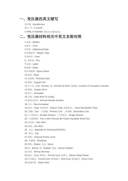
一、变压器的英文缩写变压器:transformer缩写:T. 或transf.X-FMR,X-FORMER 都是变压器的意思。
二、变压器材料相关中英文名称对照1.线架:Bobbin2.磁芯:Core3.胶带:(Adhesive)Tape4.挡墙胶带:Margin Tape5.保险丝:Fuse6. 助焊剂:Flux7.标签:Label8.树脂:Resin9.环氧树脂:Epoxy Resin10.底座:Base11.包装箱:Packing-Case12.铜箔:Copper Foil13.凡立水、清漆:Varnish 漆:Varnish Or Paint 绝缘漆:Insullac Or Insulation Varnish14.铜线:Copper Wire15.黑片:Annealed16.引线:Lead Wire Or Leads17.抽屉式胶芯:Shroud Double Section18.白片:Non-Annealed19.套管:Tube 矽质套管:Silicon Tube 热缩套管: Heat-Shrinkable Tube20..线圈:Coil 一次线圈:Primary Coil 二次线圈:Secondary Coil21.王字型胶芯:Double Section 工字型胶芯:Single Section22.三层绝缘线:Tex-e Wire Should Be Triple Insulated Wire(Tiw)23.丝包线:Ustc Wire24.绞线:Litz Wire25. 电木:Bakelite Or Phenolic(酚醛树脂)26. 铁夹:Clip27.铁桥:Channel Frame cycle28. 屏蔽物:Shielding29.塑料:Plastic 尼龙:Nylon30.硅:Silicon 胶:Rubber 硅胶:Silicon Rubber31.线束:Wiring Harness32.磁芯:Core 铁粉芯:Ferrite Core 硅钢片:Silicon-Steel Sheet33.环形磁芯:Toroid Core 棒状磁芯:Rod Core 鼓状磁芯:Drum Core34.玻璃纤维:Glass Fiber35.螺旋形,螺线管:Solenoid36. 焊锡:Solder三、变压器常用名词及术语的中英文名称对照1.变压器:Transformer2.扼流圈:Choke Coil3.滤波线圈:Line Filter4.逆变器:Inverter5.适配器:Adapter6.初始磁导率:Initial Permeability7..绝缘(体):Insulation8.功率损耗:Power Loss9.密度:Density10.顽磁、剩磁:Remanence11.电感:Inductance12.电阻:Resistance13.绝缘:Insulation14.电压:Voltage15.电流:Current16.漏电感:Leakage Inductance17.空载:Unload18.负载:Load19.符号、标记:Code20.圈数:Turn21.气隙: Gap22.剪除:Cut Off23.品质因素:Quality Factor24.浸泡:Dip Or Impregnate25.初级:Primary26.次级:Secondary27.频率:Frequency28.输出功率:Output Power29.磁通密度:Flux Density30.型号:Type31.尺寸:Size32.绕组:Winding33.疏绕:Space Or Spread34.密绕:Close Or Dense35.双线并绕:Bifilar 三线并绕 Trifilar36.额定:Rated37.材料表:Material List38.绕线层次图:Winding Construction39.线路图:Schematic Or Circuit Diagram40.外观(机械)图及尺寸:Configuration&Dimensions; Or Mechanical Dimensions41.高压测试:Hi-Pot Test42.电气特性:Electronical Character43.客户:Customer44.供应商:Suppler Supplier45.分布:Wired46.中央:Middle(Center)47.版本:Version48.制图者:Draughter49.确认、批准:Approval50.检查:Check51.发布日期:Issue Date52.固定:Fix53.焊锡:Soldering54.公差:Tolerance55.起始:Start56.结束:Finish57.样品:Sample58.规格:Spec Or Specification59.单位:Unit60.印章:Seal61.标识:Marking62.Approved 审核63.Shorting Copper 外铜带64.Solenoid 螺线管;螺线形电导管65.Withstand Voltage 耐压66.层间耐压 Layer Short67.Poor wetting 焊锡不良68、Distortion失真69、harmonic谐波70 、insertion loss插入损耗71、Saturation 饱和,磁化饱和72、Return loss 回程损耗,逆程损耗四、变压器骨架常用英文缩写ABS Acrylonitrile-butadiene-styrene 丙烯腈/丁二烯/苯乙烯共聚物AES Acrylonitrile-ethylene-styrene 丙烯腈/乙烯/苯乙烯共聚物AMMA Acrylonitrile/methyl Methacrylate 丙烯腈/甲基丙烯酸甲酯共聚物ARP Aromatic polyester 聚芳香酯AS Acrylonitrile-styrene resin 丙烯腈-苯乙烯树脂ASA Acrylonitrile-styrene-acrylate 丙烯腈/苯乙烯/丙烯酸酯共聚物CA Cellulose acetate 醋酸纤维塑料CAB Cellulose acetate butyrate 醋酸-丁酸纤维素塑料CAP Cellulose acetate propionate 醋酸-丙酸纤维素CE Cellulose plastics, general 通用纤维素塑料CF Cresol-formaldehyde 甲酚-甲醛树脂CMC Carboxymethyl cellulose 羧甲基纤维素CN Cellulose nitrate 硝酸纤维素CP Cellulose propionate 丙酸纤维素CPE Chlorinated polyethylene 氯化聚乙烯CPVC Chlorinated poly(vinyl chloride) 氯化聚氯乙烯CS Casein 酪蛋白CTA Cellulose triacetate 三醋酸纤维素EC Ethyl cellulose 乙烷纤维素EMA Ethylene/methacrylic acid 乙烯/甲基丙烯酸共聚物EP Epoxy, epoxide 环氧树脂EPD Ethylene-propylene-diene 乙烯-丙烯-二烯三元共聚物EPM Ethylene-propylene polymer 乙烯-丙烯共聚物EPS Expanded polystyrene 发泡聚苯乙烯ETFE Ethylene-tetrafluoroethylene 乙烯-四氟乙烯共聚物EVA Ethylene/vinyl acetate 乙烯-醋酸乙烯共聚物EVAL Ethylene-vinyl alcohol 乙烯-乙烯醇共聚物FEP Perfluoro(ethylene-propylene) 全氟(乙烯-丙烯)塑料FF Furan formaldehyde 呋喃甲醛HDPE High-density polyethylene plastics 高密度聚乙烯塑料HIPS High impact polystyrene 高冲聚苯乙烯IPS Impact-resistant polystyrene 耐冲击聚苯乙烯LCP Liquid crystal polymer 液晶聚合物LDPE Low-density polyethylene plastics 低密度聚乙烯塑料LLDPE Linear low-density polyethylene 线性低密聚乙烯LMDPE Linear medium-density polyethylene 线性中密聚乙烯MBS Methacrylate-butadiene-styrene 甲基丙烯酸-丁二烯-苯乙烯共聚物MC Methyl celluloseMDPE Medium-density polyethylene 中密聚乙烯MF Melamine-formaldehyde resin 密胺-甲醛树脂MPF Melamine/phenol-formaldehyde 密胺/酚醛树脂PA Polyamide (nylon) 聚酰胺(尼龙)PAA Poly(acrylic acid) 聚丙烯酸PADC Poly(allyl diglycol carbonate) 碳酸-二乙二醇酯. 烯丙醇酯树脂PAE Polyarylether 聚芳醚PAEK Polyaryletherketone 聚芳醚酮PAI Polyamide-imide 聚酰胺-酰亚胺PAK Polyester alkyd 聚酯树脂PAN Polyacrylonitrile 聚丙烯腈PARA Polyaryl amide 聚芳酰胺PASU Polyarylsulfone 聚芳砜PAT Polyarylate 聚芳酯PAUR Poly(ester urethane) 聚酯型聚氨酯PB Polybutene-1 聚丁烯-[1]PBA Poly(butyl acrylate) 聚丙烯酸丁酯PBAN Polybutadiene-acrylonitrile 聚丁二烯-丙烯腈PBS Polybutadiene-styrene 聚丁二烯-苯乙烯PBT Poly(butylene terephthalate) 聚对苯二酸丁二酯PC Polycarbonate 聚碳酸酯PCTFE Polychlorotrifluoroethylene 聚氯三氟乙烯PDAP Poly(diallyl phthalate) 聚对苯二甲酸二烯丙酯PE Polyethylene 聚乙烯PEBA Polyether block amide 聚醚嵌段酰胺PEBA Thermoplastic elastomer polyether 聚酯热塑弹性体PEEK Polyetheretherketone 聚醚醚酮PEI Poly(etherimide) 聚醚酰亚胺PEK Polyether ketone 聚醚酮PEO Poly(ethylene oxide) 聚环氧乙烷PES Poly(ether sulfone) 聚醚砜PET Poly(ethylene terephthalate) 聚对苯二甲酸乙二酯PETG Poly(ethylene terephthalate) glycol 二醇类改性PET PEUR Poly(ether urethane) 聚醚型聚氨酯PF Phenol-formaldehyde resin 酚醛树脂PFA Perfluoro(alkoxy alkane) 全氟烷氧基树脂PFF Phenol-furfural resin 酚呋喃树脂PI Polyimide 聚酰亚胺PIB Polyisobutylene 聚异丁烯PISU Polyimidesulfone 聚酰亚胺砜PMCA Poly(methyl-alpha-chloroacrylate) 聚α-氯代丙烯酸甲酯PMMA Poly(methyl methacrylate) 聚甲基丙烯酸甲酯PMP Poly(4-methylpentene-1) 聚4-甲基戊烯-1PMS Poly(alpha-methylstyrene) 聚α-甲基苯乙烯POM Polyoxymethylene, polyacetal 聚甲醛PP Polypropylene 聚丙烯PPA Polyphthalamide 聚邻苯二甲酰胺PPE Poly(phenylene ether) 聚苯醚。
电气专业毕业设计外文翻译2--变压器

外文资料翻译TRANSFORMER1. INTRODUCTIONThe high-voltage transmission was need for the case electrical power is to be provided at considerable distance from a generating station. At some point this high voltage must be reduced, because ultimately is must supply a load. The transformer makes it possible for various parts of a power system to operate at different voltage levels. In this paper we discuss power transformer principles and applications.2. TOW-WINDING TRANSFORMERSA transformer in its simplest form consists of two stationary coils coupled by a mutual magnetic flux. The coils are said to be mutually coupled because they link a common flux.In power applications, laminated steel core transformers (to which this paper is restricted) are used. Transformers are efficient because the rotational losses normally associated with rotating machine are absent, so relatively little power is lost when transforming power from one voltage level to another. Typical efficiencies are in the range 92 to 99%, the higher values applying to the larger power transformers.The current flowing in the coil connected to the ac source is called the primary winding or simply the primary. It sets up the flux φ in the core, which varies periodically both in magnitude and direction. The flux links the second coil, called the secondary winding or simply secondary. The flux is changing; therefore, it induces a voltage in the secondary by electromagnetic induction in accordance with Lenz’s law. Thus the primary receives its power from the source while the secondary supplies this power to the load. This action is known as transformer action.3. TRANSFORMER PRINCIPLESWhen a sinusoidal voltage V p is applied to the primary with the secondary open-circuited, there will be no energy transfer. The impressed voltage causes a small current Iθ to flow in the primary winding. This no-load current has two functions: (1) it produces the magnetic flux in the core, which varies sinusoidally between zero and φm, where φm is the maximum value of the core flux; and (2) it provides a component to account for the hysteresis and eddy current losses in the core. There combined losses are normally referred to as the core losses.The no-load current Iθ is usually few percent of the rated full-load current of the transformer (about 2 to 5%). Since at no-load the primary winding acts as a large reactance due to the iron core, the no-load current will lag the primary voltage by nearly 90º. It is readily seen that the current component I m= I0sinθ0, called the magnetizing current, is 90º in phase behind the primary voltage V P. It is this component that sets up the flux in the core; φ is therefore in phase with I m.The second component, I e=I0sinθ0, is in phase with the primary voltage. It is the current component that supplies the core losses. The phasor sum of these twocomponents represents the no -load current, ore m o I I I +=It should be noted that the no -load current is distortes and nonsinusoidal. This is the result of the nonlinear behavior of the core material.If it is assumed that there are no other losses in the transformer, the induced voltage In the primary, E p and that in the secondary, E s can be shown. Since the magnetic flux set up by the primary winding ,there will be an induced EMF E in the secondary winding in accordance with Faraday’s law, namely, t N E ∆∆⋅=/ϕ. This same flux also links the primary itself, inducing in it an EMF, E p . As discussed earlier, the induced voltage must lag the flux by 90º, therefore, they are 180º out of phase with the applied voltage. Since no current flows in the secondary winding, E s =V s . The no -load primary current I 0 is small, a few percent of full -load current. Thus the voltage in the primary is small and V p is nearly equal to E p . The primary voltage and the resulting flux are sinusoidal; thus the induced quantities E p and E s vary as a sine function. The average value of the induced voltage given byE avg = turns× change in flux in a given time given timewhich is Faraday’s law applied to a finite time interval. It follows thatE avg = N 21/(2)m f ϕ = 4fNφm which N is the number of turns on the winding. Form ac circuit theory, the effective or root -mean -square (rms) voltage for a sine wave is 1.11 times the average voltage; thusE = 4.44fNφmSince the same flux links with the primary and secondary windings, the voltage per turn in each winding is the same. HenceE p = 4.44fN p φmandE s = 4.44fN s φmwhere E p and Es are the number of turn on the primary and secondary windings, respectively. The ratio of primary to secondary induced voltage is called the transformation ratio. Denoting this ratio by a, it is seen that a = p sE E = p s N N Assume that the output power of a transformer equals its input power, not a bad sumption in practice considering the high efficiencies. What we really are saying is that we are dealing with an ideal transformer; that is, it has no losses. ThusP m = P outorV p I p × primary PF = V s I s × secondary PFwhere PF is the power factor. For the above -stated assumption it means that the power factor on primary and secondary sides are equal; thereforeV p I p = V s I sfrom which is obtained p s V V = p s I I ≌ p sE E ≌ a It shows that as an approximation the terminal voltage ratio equals the turns ratio. The primary and secondary current, on the other hand, are inversely related to the turns ratio. The turns ratio gives a measure of how much the secondary voltage is raised or lowered in relation to the primary voltage. To calculate the voltage regulation, we need more information.The ratio of the terminal voltage varies somewhat depending on the load and its power factor. In practice, the transformation ratio is obtained from the nameplate data, which list the primary and secondary voltage under full -load condition.When the secondary voltage V s is reduced compared to the primary voltage, the transformation is said to be a step -down transformer: conversely, if this voltage is raised, it is called a step -up transformer. In a step -down transformer the transformation ratio a is greater than unity (a>1.0), while for a step -up transformer it is smaller than unity (a<1.0). In the event that a=1, the transformer secondary voltage equals the primary voltage. This is a special type of transformer used in instances where electrical isolation is required between the primary and secondary circuit while maintaining the same voltage level. Therefore, this transformer is generally knows as an isolation transformer.As is apparent, it is the magnetic flux in the core that forms the connecting link between primary and secondary circuit. In section 4 it is shown how the primary winding current adjusts itself to the secondary load current when the transformer supplies a load.Looking into the transformer terminals from the source, an impedance is seen which by definition equals V p / I p . From p s V V = p s I I ≌ p sE E ≌ a , we have V p = aV s and I p = I s /a.In terms of V s and I s the ratio of V p to I p isp p V I = /s s aV I a= 2s s a V I But V s / I s is the load impedance Z L thus we can say thatZ m (primary) = a 2Z LThis equation tells us that when an impedance is connected to the secondary side, it appears from the source as an impedance having a magnitude that is a 2 times its actual value. We say that the load impedance is reflected or referred to the primary. It is this property of transformers that is used in impedance -matching applications.译文变压器1. 介绍要从远端发电厂送出电能,必须应用高压输电。
变压器专业英语翻译
变压器专业英语翻译1、元件设备三绕组变压器:three-column transformer ThrClnTrans双绕组变压器:double-column transformer DblClmnTrans 电容器:Capacitor并联电容器:shunt capacitor电抗器:Reactor母线:Busbar输电线:TransmissionLine发电厂:power plant断路器:Breaker刀闸(隔离开关):Isolator分接头:tap电动机:motor-------------------------------------------------------------------------------- 2、状态参数有功:active power无功:reactive power电流:current容量:capacity电压:voltage档位:tap position无功损耗:reactive loss有功损耗:active loss功率因数:power-factor功率:power功角:power-angle电压等级:voltage grade空载损耗:no-load loss铁损:iron loss铜损:copper loss空载电流:no-load current阻抗:impedance正序阻抗:positive sequence impedance 负序阻抗:negative sequence impedance 零序阻抗:zero sequence impedance电阻:resistor电抗:reactance电导:conductance电纳:susceptance无功负载:reactive load 或者QLoad有功负载: active load Load遥测:YC(telemetering)遥信:YX励磁电流(转子电流):magnetizing current 定子:stator功角:power-angle上限:upper limit下限:lower limit并列的:apposable高压: high voltage低压:low voltage中压:middle voltage电力系统power system发电机generator励磁excitation励磁器excitor电压voltage电流current母线bus变压器transformer升压变压器step-up transformer高压侧high side输电系统power transmission system输电线transmission line固定串联电容补偿fixed series capacitor compensation 稳定stability电压稳定voltage stability功角稳定angle stability暂态稳定transient stability电厂power plant能量输送power transfer交流AC装机容量installed capacity电网power system落点drop point开关站switch station双回同杆并架double-circuit lines on the same tower 变电站transformer substation补偿度degree of compensation高抗high voltage shunt reactor无功补偿reactive power compensation故障fault调节regulation裕度magin三相故障three phase fault故障切除时间fault clearing time极限切除时间critical clearing time切机generator triping高顶值high limited value强行励磁reinforced excitation线路补偿器LDC(line drop compensation)机端generator terminal静态static (state)动态dynamic (state)单机无穷大系统one machine - infinity bus system 机端电压控制AVR电抗reactance电阻resistance功角power angle有功(功率)active power无功(功率)reactive power功率因数power factor无功电流reactive current下降特性droop characteristics斜率slope额定rating变比ratio参考值reference value电压互感器T分接头tap下降率droop rate仿真分析simulation analysis传递函数transfer function框图block diagram受端receive-side裕度margin同步synchronization失去同步loss of synchronization 阻尼damping摇摆swing保护断路器circuit breaker电阻:resistance电抗:reactance阻抗:impedance电导:conductance电纳:susceptance导纳:admittance电感:inductance电容: capacitance-------------------------------------------------------------------------------- Absorber Circuit ——吸收电路AC/AC Frequency Converter ——交交变频电路AC power control ——交流电力控制AC ower Controller ——交流调功电路AC Power Electronic Switch ——交流电力电子开关Ac Voltage Controller ——交流调压电路Asynchronous Modulation ——异步调制Baker Clamping Circuit ——贝克箝位电路Bi-directional Triode Thyristor ——双向晶闸管Bipolar Junction Transistor-- BJT ——双极结型晶体管Boost-Buck Chopper ——升降压斩波电路Boost Chopper ——升压斩波电路Boost Converter ——升压变换器Bridge Reversible Chopper ——桥式可逆斩波电路Buck Chopper ——降压斩波电路Buck Converter ——降压变换器Commutation ——换流Conduction Angle ——导通角Constant Voltage Constant Frequency --CVCF ——恒压恒频Continuous Conduction--CCM ——(电流)连续模式Control Circuit ——控制电路Cuk Circuit ——CUK斩波电路Current Reversible Chopper ——电流可逆斩波电路Current Source Type Inverter--CSTI ——电流(源)型逆变电路Cycloconvertor ——周波变流器DC-AC-DC Converter ——直交直电路DC Chopping ——直流斩波DC Chopping Circuit ——直流斩波电路DC-DC Converter ——直流-直流变换器Device Commutation ——器件换流Direct Current Control ——直接电流控制Discontinuous Conduction mode ——(电流)断续模式displacement factor ——位移因数distortion power ——畸变功率double end converter ——双端电路driving circuit ——驱动电路electrical isolation ——电气隔离fast acting fuse ——快速熔断器fast recovery diode ——快恢复二极管fast recovery epitaxial diodes ——快恢复外延二极管fast switching thyristor ——快速晶闸管field controlled thyristor ——场控晶闸管flyback converter ——反激电流forced commutation ——强迫换流forward converter ——正激电路frequency converter ——变频器full bridge converter ——全桥电路full bridge rectifier ——全桥整流电路full wave rectifier ——全波整流电路fundamental factor ——基波因数gate turn-off thyristor——GTO ——可关断晶闸管general purpose diode ——普通二极管giant transistor——GTR ——电力晶体管half bridge converter ——半桥电路hard switching ——硬开关high voltage IC ——高压集成电路hysteresis comparison ——带环比较方式indirect current control ——间接电流控制indirect DC-DC converter ——间接DC- DC转换器insulated-gate bipolar transistor---IGBT ——绝缘栅双极晶体管intelligent power module---IPM ——智能功率模块integrated gate-commutated thyristor---IGCT ——集成门极换流晶闸管inversion ——逆变latching effect ——擎住效应leakage inductance ——漏感light triggered thyristo---LTT ——光控晶闸管line commutation ——电网换流load commutation ——负载换流loop current ——环流。
变压器英译词汇表.doc
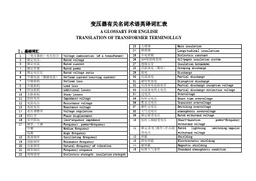
感应耐压试验
Induced overvoltage withstand test
72
(突发)短路试验
Short –circuit test
73
互感器的负荷
Burden of an instrument transformer
74
额定负荷(互感器)
Rated burden (of an instrument transformer)
44
磁屏蔽
Magnetic shielding
45
标准大气条件
Standard atmospheric condition
46
视在电荷
Apparent charge
47
全波雷电冲击
Full wave lig
Chopped wave lightning impulse
49
冲击伏秒特性
Voltage time characteristics of impulse
50
爬电距离
Creepage distance
51
体积电阻
Volume resistance
52
截断时间
Time to chopping
53
波前时间,视在波前时间
Time to crest, virtual front time
Absorption ratio of insulation resistance(R60/R15)
68
避雷器
Surge arrestor
69
避雷器的残压
Residual (discharge )voltage of an arrestor
70
绝缘材料耐温等级
Transformer变压器(外文文献翻译)

Transformer变压器One of the most valuable apparatus in electric power system is the transformer, for it enables us to utilize different voltage levels across the system for the most economical value。
Generation of power at the synchronous machine level is normally at a relatively low voltage,which is most desirable economically.Stepping up of this generated voltage to high voltage,extra—high voltage or even to ultra—high voltage is done through power transformers to suit the power transmission requirement to minimize losses and increase the transmission capacity of the lines.This transmission voltage level is then stepped down in many stages for distribution and utilization purposes.电力系统中的最有价值之一是器具的变压器,它使我们能够利用不同电压等级,整个系统的最经济的值.通常在较低功率在同步计算机级别的一代是voltage,which,是最理想的economically.Stepping 高voltage,extra 高电压该生成电压或甚至超高电压通过以适应电力传输的要求,尽量减少损失的电力变压器和增加lines.This 输电电压等级的输电量然后走在很多阶段的分布和利用的目的最有价值的一个装置在电力系统变压器,因为它使我们能够利用不同系统电压水平在最经济的价值.一代的电力水平同步机通常以较低的电压,这是最理想的economically.Stepping这产生电压高压、超高压甚至是通过高压电源变压器适应电力传动要求减少损失,提高传输容量的lines。
变压器专业英语词汇

变压器专业英语词汇变压器\Transformer\F配电变压器\Distribution Transformer\F电力变压器\Power Transformer\F干式变压器\Dry Type Transformer\F油浸式变压器\Oil Immersed Transformer\F升压变压器\Step-up Transformer\F降压变压器\Step-down Transformer\F特种变压器\Special Transformer\F牵引变压器\Traction transformer\F电炉变压器\Furnace transformer\F自耦变压器\Auto-transformer\F储油柜\Oil tank\F顶层油温指示装置\Top oil temperature indication device\F 油位指示\Oil level indication\F释压阀\Pressure release valve\F瓦斯继电器\Gas relay\F油温指示\Oil temperature indication\F绕组温度指示\Winding temperature indication\F风机\Cooling fan\F过滤阀\Filtration valve\F报警\Alarming\F脱扣\Tripping\F互感器\Instrument transformer\F测试\Test\F例行\Routine\F温升\Temperature rise\F冲击试验\Impulse test\F绕组\Winding\F绝缘\Insulation\F绝缘电阻\Insulation resistant\F容量\Capacity\F短路\Short-circuit\F阻抗\Impedance\F负载\Load\F损耗\Loss\F有载\On-load\F无载\Off-load\F空载\Off-load\F满载\Full-load\F铁芯\Iron core\F空载电流\Off-load current\F温度\Temperature\F相对湿度\Relative humidity\F描述\Description\F载荷\Load\F绝缘等级\Insulation level\F等级\Level\F海拔高度\Altitude\F有载分接开关\On-load tap changer\F气压\Air pressure\F隔离开关\Disconnector\F(三相系统中的)首开极系数first-pole-to-clear factor (in a three-phase system)变压器核心部件英语词汇变压器铁心Transformer core(magnetic circuit)变压器线圈Transformer winding线圈端部绝缘End insulation of winding上部夹件Upper clamping下部夹件Lower clamping分接引线Tapping leads引线支架Supporting frame for leads高压套管均压球Equipotential shielding for HV bushing高压引线High-voltage leads低压引线Low-voltage leads线圈压紧螺栓Winding compressing bolt器身定位装置Positioning divice for active-part垫脚Foot-pad小车支架及滚轮Bogie frame and wheel油箱Tank箱底Tank bottom箱盖及箱沿Tank cover and tank rim垫脚垫块Suppoting block for foot-pad联管接头(法兰)Tube connetor (connecting flange)油箱直立加强铁Vertical stiffening channel of tank wall油样活门Oil asmping valve放油活门Oil draining valve管式散热器Tubular radiator放油塞Oil draining plug放气塞Air exhausting plug风扇支架Supporting frame for fan motors风扇及电机Fan and motor风扇接线盒Connecting box for fan motors储油柜联管Elbow joint for conservator气体继电器Gas relay储油柜Conservator油位指示计Oil-level indicator有载开关用储油柜Conservator for OLTC有载开关用气体继电器Gas relay for OLTC联管Tube connector名牌Rating plate温度计Thermometer指示仪表柜Cabinet panel for indicating instruments风扇控制柜Cabinet panel for fan motor control压力释放阀Pressure-relief valve主排气导管(导气管)Main gas-conduit分支导气管Branching gas-filter滤油接口(蝶阀)Tube connector for oil-filter(butterfly valve) 温度计座Thermometer socket储油柜支架Supporting frame for conservator高压0相套管HV bushing phase 0(neutral)高压套管HV bushing低压套管LV bushing有载分接开关On-load tap-changer(OLTC)有载开关操动机构Operating mechanism of OLTC垂直传动轴Vertical driving shaft水平传动轴Horizontal driving shaft伞齿轮盒Bevel gear box防雨罩及联轴节Drip-proof cap and coupling联轴节Coupling高压套管储油柜Conservator for HV bushing相间隔板Interphase insulating barrier吊拌Lifting lug安装轨道Installation rail相序标志牌Designation mark of phase sequence接地螺栓Earthing bolt。
变压器用英语怎么说
变压器用英语怎么说变压器是利用电磁感应的原理来改变交流电压的装置,主要功能有电压变换、电流变换、阻抗变换、隔离、稳压等。
那么你知道变压器用英语怎么说吗?接下来跟着店铺来学习一下吧。
变压器的英语说法1:transformer变压器的英语说法2:voltage changer变压器相关英语表达:mains transformer;电源变压器step-down transformer;降压变压器step-up transformer;升压变压器output transformer;输出变压器input transformer输入变压器变压器的英语例句:1. He switched off the transformer and the buzzing stopped.他关掉变压器,嗡嗡声就消失了。
2. Keep away from the transformer.不要靠近那个变压器.3. We traced the trouble to a faulty transformer.我们查出故障出在一个有毛病的变压器上.4. The transformer isolates the transistors with regard to d -c bias voltage .变压器可在两个晶体管之间隔离直流偏压.5. A step - down transformer has a turns ratio less than 1.降压变压器的匝数比小于1.6. The magnetic cores of transformers and other apparatus are laminated.把变压器及其它仪器的磁心分层.7. A linear differential transformer has three coils.一个直线差动变压器有三个线圈.8. Several distributor transformers had fallen from the poles, and secondary wires and service drops were down.几个配电变压器从电线杆上摔下来, 副线及吊饰也垂下来.9. Fig. 9 shows schematically the application of a differential transformer to measurement of liquid column height.应用差动变压器测定液柱高度大致如图9所示.10. The signal is fed into a filter - amplifier which is transformercoupled to the video - detector.这个信号送到滤波器 - 放大器,它是由变压器耦合到视频检波器的.11. Advanced Transformer fastening structure, the ability to short - circuit resistance.变压器紧固结构先进, 抗短路能力强.12. HU Jing - sheng . Transformer Economic Operation. Beijing: China Power Press, 1999.胡景生. 变压器经济运行. 北京: 中国电力出版社, 1999.13. The paper also points out the direction of differential relay development.最后,本文指出了微机变压器差动保护的发展方向.14. It is very complicated to model transformer in transient calculation.在电磁暂态计算中,变压器是较难模拟的元件之一.15. Caution: the soldering iron transformer is designed for short burst operation.警告: 烙铁变压器是专为短期爆裂的运作.。
变压器常用中英对照
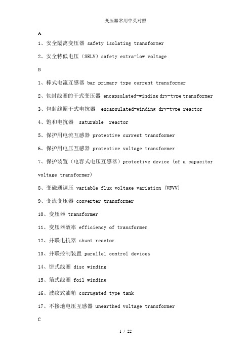
A1、安全隔离变压器 safety isolating transformer2、安全特低电压(SELV)safety extra-low voltageB1、棒式电流互感器 bar primary type current transformer2、包封线圈的干式变压器 encapsulated-winding dry-type transformer3、包封线圈干式电抗器 encapsulated-winding dry-type reactor4、饱和电抗器 saturable reactor5、保护用电流互感器 protective current transformer6、保护用电压互感器 protective voltage transformer7、保护装置(电容式电压互感器)protective device (of a capacitor voltage transformer)8、变磁通调压 variable flux voltage variation (VFVV)9、变流变压器 converter transformer10、变压器 transformer11、变压器效率 efficiency of transformer12、并联电抗器 shunt reactor13、并联控制装置 parallel control devices14、饼式线圈 disc winding15、箔式线圈 foil winding16、波纹式油箱 corrugated type tank17、不接地电压互感器 unearthed voltage transformerC1、操作计数器 operation counter2、操作循环 cycle of operation3、测量用电流互感器 measuring current transformer4、测量用电压互感器 measuring voltage transformer5、层式线圈 layer winding6、叉花纠结式线圈 sandwich-interleaved winding7、厂用变压器 (发电厂用变压器) station service transformer8、插入电容式线圈 capacitor shield winding9、充满油的密封系统 sealed, completed filled system10、串级(电磁)式电流互感器 cascade (inductive) current transformer11、串级(电磁)式电压互感器 cascade (inductive) voltage transformer12、串级试验变压器 cascade transformer13、串联电抗器 series reactor14、串联绕组 series winding15、船用变压器 marine transformer16、触头组 set of contacts17、储油柜 oil conservator18、储油柜系统 conservator system19、磁分路 magnetic shunt20、磁箱式电流互感器 porcelain-case type current transformer21、磁性调压器 magnetic control voltage regulator22、粗调选择器 coarse change-over selectorD1、带气垫的密封式油箱系统 sealed-tank system with gas cushion2、带散热管的油箱 tank with bend pipe3、单铁心式电流互感器 single-core type current transformer4、单相单柱旁轭式铁心 single-phase three-limb core5、单相二柱式铁心 single-phase two-limb core6、倒立式电流互感器 inverter-type current transformer7、电磁单元(电容式电压互感器) electromagnetic unit (of a capacitor voltage transformer)8、电动机构 motor-drive mechanism9、电动机构的手动操作 manual operation of motor-device mechanism10、电化学用整流变压器 electro-chemistry rectifier transformer11、点火变压器 ignition transformer12、电弧炉变压器 arc furnace transformer13、电抗电压 reactance voltage14、电抗器 reactor15、电缆式电流互感器 cable type current transformer16、电力变压器 power transformer17、电铃变压器 bell transformer18、电流互感器 current transformer19、电流扩大值(测量用电流互感器的)extended rating current(of a measuring current transformer )20、电流误差 current error21、电炉变压器 furnace transformer22、电容分压器(电容式电压互感器)capacitor voltage divider (of a capacitor voltage transformer)23、电容分压器的分压比 voltage ratio of a capacitor divider24、电容式电压互感器 capacitor voltage transformer25、电压互感器 voltage transformer26、电压降或电压升(指定负载下的)voltage drop or rise for a specified load condition27、电压调整率(指定复式下的)voltage regulation for a specified load condition28、电压误差 voltage error29、电阻电压 resistance voltage30、电阻炉变压器 resistance furnace transformer31、电阻式温度计 resistance-type thermometer32、叠积式铁心 laminated core33、低压端子(电容式电压互感器的)low voltage terminal (of a capacitor voltage transformer)34、低压绕组 low-voltage winding35、端(部电容)环 end ring36、短路匝 short-circuited turn37、短路阻抗(一对绕组的)short-circuit impedance (of a pair ofwinding)38、端(部电容)屏 end screen39、对应端子 corresponding terminals40、独立绕组变压器 separate winding transformer41、多框式铁心 multi frame type core42、多绕组变压器 multi-winding transformer43、多铁心式电流互感器 multi-core type current transformer44、惰性气体压力系统 inert gas pressure systemE1、额定参数 rated quantities2、额定电流(变压器或并联电抗器绕组上的)rated current(of a winding of a transformer or shunt reactor)3、额定电流比(电流互感器的)rated transformer ratio (of a current transformer)4、额定电压比(电流互感器的)rated transformer ratio (of a voltage transformer)5、额定电压比(绕组的)rated voltage ratio (of a winding)6、额定电压比(电压互感器的)rated transformation ratio (of a voltage transformer)7、额定电压系数 rated voltage factor8、额定动稳定电流 rated dynamic current9、额定短时电流 rated short-time current10、额定短时热电流(电流互感器的)rated short-time thermal current (of a current transformer)11、额定二次电流(电流互感器的)rated secondary current (of a current transformer)12、额定二次电压(电压互感器的)rated secondary voltage (of a voltage transformer)13、额定阀侧电流 rated current on valve side14、额定阀侧电压 rated current on line side15、额定阀侧视在功率 rated apparent power on valve side16、额定负荷 rated burden17、额定级电压 rated through-current18、额定绝缘水平 rated insulation level19、额定连续电流 rated continuous current20、额定连续热电流(电流互感器)rated continuous thermal current (of a current transformer)21、额定频率 rated frequency22、额定容量 rated power23、额定输出(互感器的)rated output (of an instrument transformer)24、额定输出电压 rated output voltage25、额定输入电压 input voltage26、额定通过电流 rated through current27、额定网侧电流 rated current on line side28、额定网侧电压 rated voltage on line side29、额定网侧视在功率 rated apparent power on valve line30、额定仪表限值一次电流(电流互感器的)rated instrument limit primary current31、额定一次电流(电流互感器的)rated primary current (of a current transformer)32、额定一次电压(电压互感器的)rated primary voltage (of a voltage transformer)33、额定值 rating34、额定准确限值一次电流(保护用电流互感器的)rated instrument limit primary current35、二次电流 secondary current36、二次电路 secondary circuit37、二次电压 secondary voltage38、二次极限感应电势 secondary limiting e.m.f39、二次绕组(变压器的)secondary winding (of a current transformer)40、二次绕组(电压互感器的)secondary winding (of a voltage transformer)II(防止点击)变压器 class II transformerF1、阀侧绕组 valve side winding2、发电厂自用变压器(简称:厂用变压器) station service transformer3、发电机变压器 generator transformer4、放电线圈 discharge coil5、反角环 angle ring (cap-ring)6、非包封线圈干式变压器non-encapsulated-winding dry-type transformer7、非包封线圈干式电抗器 non-encapsulated-winding dry-type reactor8、非封闭干式变压器 non-enclosed dry transformer9、非耐短路变压器 non-short-circuit proof transformer10、封闭干式变压器 enclosed dry transformer11、风冷(AF)force-air cooling12、分接 tapping (tap)13、分接参数 tapping quantities14、分接变换操作 tap-change operation15、分接变换指示器 tap-change in progress indicator16、分接电压比(一对绕组的)tapping voltage ratio (of a pair of windings)17、分接范围 tapping range18、分接工况 tapping duty19、分接级 tapping step20、分接位置指示器 tap position indicator21、分接选择器 tap-selector22、分接因数 tapping factor23、分裂式变压器 dual-low-voltage transformer24、分相封闭母线 isolated phase bus25、负分接 minus tapping26、负荷(互感器的)burden (of an instrument transformer)27、复合误差(电流互感器的)composite error (of a current transformer)28、附加绝缘 supplementary insulation29、附加绕组 auxiliary winding30、附加损耗 supplementary load loss31、复绕式电流互感器 compound-wound current transformer32、负载损耗 load lossG1、干式变压器 dry-type transformer2、干式电抗器 dry-type transformer3、感应调压器 induction-voltage regulator4、感应自动调压器 automatic induction-voltage regulator5、高压电容器(电容式电压互感器的)high voltage capacitor (of a capacitor voltage transformer)6、高压端子(电容式电压互感器的)high voltage terminal (of a capacitor voltage transformer)7、高压绕组 high-voltage winding8、隔爆变压器 flame-proof transformer9、隔离变压器 isolating transformer10、隔膜式油保护系统 diaphragm-type oil preservation system11、公共绕组 common winding12、工频感应炉变压器 power frequency induction furnace transformer13、共箱隔相封闭母线 segregated phase bus14、工作分接位置数 number of service tapping positions15、拐点电压 knee point voltage16、贯穿式电流互感器 through-type current transformer17、管式散热器 pipe-type radiator18、滚动接触电刷 rolling type current collector19、过电流闭锁装置 over current blocking device20、过渡触头 transition contacts21、过渡阻抗 transition impedance22、固有分接位置数 number of service tapping positionsH1、恒磁通调压 constant flux voltage variation(CFVV)2、虹吸净油器(净油器) oil(siphon)filter3、滑动接触电刷sliding type current collector4、互感器 instrument transformer5、恢复电压 recovery voltage6、户内式 indoor type7、混合调压 combined voltage variation8、户外式 outdoor typeJ1、降低容量的分接 reduced-power tapping2、降压变压器 step-down transformer3、夹件clamps4、交叠式线圈sandwich winding5、角环 angle ring6、加强绝缘 reinforced insulation7、基本绝缘 basic insulation8、接触调压器 variable transformer9、接触自动调压器 automatic variable regulator10、接地变压器 earthing transformer(neutral coupler)11、接地电压互感器 earthed voltage transformer12、介质损耗因数 dielectric dissipation factor13、静电环 electrostatic ring14、静电屏 electrostatic shielding15、净油器 oil(siphon) filter16、紧急脱扣装置 emergency tripping device17、纠结-连续式线圈 inter leaved and continuous winding18、纠结式线圈 inter leaved winding19、极限开关 limit switch20、机械端位止动装置 mechanical end stop21、极性选择器 reversing change-over selector22、局部放电 partial discharge23、绝缘热稳定性(电流互感器的)dielectric thermal stability(ofa current transformer)K1、开断电流 switched current2、开口三角形联结 open delta connection3、开路绕组 open winding4、开路中间电压(电容式电压互感器的)open-circuit intermediatevoltage(of a capacitor voltage transformer)5、壳式变压器 shell-type transformer6、矿热炉变压器 ore furnace transformer7、矿用变压器 mining transformer(general type)8、矿用隔爆移动变电站 mining flame proof movable substation9、空心电抗器 reactor with air core10、空载电流 no-load current11、空载损耗 no-load loss12、控制用变压器 control transformer13、扩大额定值的电流互感器extend rating type currenttransformerL1、累加用电力互感器 summation current transformer2、冷却器 cooler3、联结组标号 connection symbol4、联络变压器 system-interconnection transformer5、连续式线圈 continuous winding6、励磁电流(电流互感器的)exciting current (of a currenttransformer)7、励磁绕组 energizing winding8、零序电流互感器(剩余电流互感器)residual current transformer9、零序电压互感器(剩余电压互感器)residual voltage transformer10、零序阻抗 zero-sequence impedance11、例行试验 routine test12、滤波电抗器 tuning(filter)reactor13、螺旋式线圈 helical windingM1、满容量分接 full-power of a winding2、密封式变压器 sealed transformer3、密封式电抗器 sealed reactor4、母线式电流互感器 bus-type current transformerN1、耐短路变压器 short-circuit proof transformer2、内部负荷(电流互感器的)internal burden(of a current transformer)3、内屏蔽式线圈 capacitor shield windingO1、耦合绕组 coupling windingP1、旁轭 magnetic return path2、配电变压器 distribution transformer3、膨胀器 expander4、片式散热器 panel-type radiator5、平波电抗器 smoothing reactor6、平衡电抗器 interphase reactor7、平衡绕组 balancing winding8、平面式邮箱 plane type tank9、匹配用电流互感器 current matching transformer10、匹配用电压互感器 voltage matching transformer11、P 级 performance Class AQ1、强迫油循环导向冷却 forced-directed oil cooling2、强迫油循环风冷(OFAF)forced-oil and forced-air cooling3、强迫油循环水冷(OFWF)forced-oil and water cooling4、钳式电流互感器 split core type current transformer5、牵引变压器 traction transformer6、牵引整流变压器 traction rectifier transformer7、起动电抗器 starting reactor8、起动自耦变压器 starting auto-transformer9、切换开关 diverter switch10、器身 active part11、气体继电器 gas relay;buchholz relay12、全封闭干式变压器 totally enclosed dry-type transformer13、全绝缘电流互感器 fully insulated current transformer14、全自保护变压器completely self-protected distributiontransformer15、驱动机构 driving mechanism16、曲折形联结 zigzag connectionR1、绕线式电流互感器 wound primary type current transformer2、绕组 winding3、绕组的分接电流 tapping power of a winding4、绕组的分接电压 tapping voltage of a winding5、绕组的分接容量 tapping power of a winding6、绕组的分级绝缘 non-uniform insulation of a winding7、绕组的全绝缘 uniform insulation of a winding8、绕组联结图 connection diagram of windings.S1、三角形联结 delta connection2、Ⅲ类(防止电击)变压器 class Ⅲ transformer3、Ⅲ类照明设备用变压器 transformer for class Ⅲ luminaires4、散热器 radiator5、三相三柱旁轭式铁心 three-phase three-limb core6、三相三柱式铁心 three-phase three-limb core7、三相中性点电抗器three-phase neutral reactor8、设备最高电压Um highest voltage for equipment Um9、声功率级(Lw) sound power level10、升压变压器 step-up transformer11、声压级(Lp) sound pressure level12、剩余电流 residual current13、剩余电流互感器 residual current transformer14、剩余电压 residual voltage15、剩余电压互感器 residual voltage transformer16、剩余电压绕组 residual voltage winding17、实际电流比(电流互感器的)actual transformation ratio (of acurrent transformer)18、实际电压比(电压互感器的)actual transformation ratio(of avoltage transformer)19、试验变压器 testing transformer20、双重绝缘double insulation21、双功能电压互感器 dual purpose voltage transformer22、双绕组变压器 two-winding transformer23、输出电压范围 output voltage range24、输入电压范围 input voltage range25、树脂浇注式电流互感器 cast-resin type current transformer26、树脂浇注式电压互感器 cast resin type voltage transformer27、速饱和电流互感器 rapid-saturable current transformer28、损耗比 loss ratio29、损耗变动量power loss variationT1、套管 bushing2、套管式电流互感器 bushing type current transformer3、特殊试验 special test4、调谐电抗器 tuning(filter) reactor5、调压器 voltage regulator6、铁轭 yoke7、铁心 core8、铁心接地端子earthed terminal for core9、铁心柱 core limb10、通断触头 main switch contacts11、桶式邮箱 barrel type tank12、同心式线圈 concentric windingW1、网侧绕组 line side winding2、玩具用变压器 transformer for toys3、稳定绕组 stabilizing winding4、温升 temperature rise5、稳压精度 accuracy of a voltage stabilizing6、误差补偿 error compensation7、无励磁分接开关 off-circuit tap-changer8、无励磁调压变压器off-circuit-tap-changing transformer9、无危害式变压器(保安式变压器)fail-safe transformerX1、线段 section2、相绕组 phase winding3、箱式变电站 integral unit4、相位差 phase displacement5、相位移(变压器的)phase displacement(for a transformer)6、限流电抗器 current-limiting reactor7、线路端子line terminal8、线圈 coil9、线匝 turn10、消弧电抗器arc-suppression reactor11、消弧线圈 arc-suppression reactor12、消弧电抗器(消弧线圈)的额定电流 rated current of an arcsuppression reactor13、型式试验type test14、星形联结 star connection15、信号温度计pressure-type thermometer16、心式变压器core-type transformer17、吸湿器 radiator18、吸收比 dielectric absorption ratio19、选择开关 selector switch20、循环电流 switched currentY1、压力释放装置 pressure relief device2、压力式温度计 pressure-type thermometer3、盐浴炉变压器 salt bath furnace transformer4、仪表保安系数(FS)instrument security factor5、一次电流 primary current6、一次电压 primary voltage7、一次绕组(变压器的)primary winding(of a voltage transformer)8、一次绕组(电流互感器的)primary winding (of a currenttransformer)9、一次绕组(电压互感器的)primary winding(of a voltagetransformer)10、I 类(防止电击)变压器 class I transformer11、移圈调压器 moving-coil voltage regulator12、油保护系统 oil preservation system13、油流继电器 oil-flow relay14、油浸式变压器 oil-immersed type transformer15、油浸式电抗器 oil-immersed type reactor16、油位计 oil level indicator17、有载分接开关 on-load tap-changer18、有载调压变压器 on-load-tap-changing transformer19、油中溶解气体分析dissolved gas(in oil)analysisZ1、(线)匝 turn2、再起动装置 restarting device3、增压变压器 booster transformer4、正分接 plus tapping5、整流变压器 rectifier transformer6、直流互感器 direct current instrument transformer7、支柱式电流互感器 support type current transformer8、中间式电流互感器 current matching transformer9、中频变压器 intermediate-frequency transformer10、中性点端子neutral terminal11、中性点接地电抗器 neutral-earthing reactor12、中性点耦合器(中性点耦合器)earthing transformer(neutralcoupler)13、中压电容器(电容式电压互感器的)intermediate voltage capacitor(of a capacitor voltage transformer)14、电压端子(电容式电压互感器的)intermediate voltage terminal (of a capacitor voltage transformer)15、中压绕组 intermediate-voltage winding16、钟罩式油箱 bell type tank17、转换选择器 change-over selector18、主触头 main contacts19、主分接(额定分接)principal tapping20、逐级控制 step-by-step control21、准确级 accuracy class22、准确限值系数(保护用电流互感器的)accuracy limit factor(ofa protective current transformer)23、主(电容)屏 main capacitor plate24、柱上式 pole-type25、自动调压器 automatic voltage regulator26、自动调压速度 response speed27、自冷(AN) natural air cooling; self-cooling28、自耦变压器 auto-transformer29、自耦复绕式电流互感器 auto-compound current transformer30、自耦式互感器 instrument auto-transformer31、总损耗 total loss32、组合式变电站 integral unit substation33、组合式互感器 combined transformer34、最大额定级电压 maximum rated step voltage35、最大额定通过电流 maximum rated through-current36、阻抗电压(对于主分接)impedance voltage at rated current(for the principal tapping)37、阻尼电抗器 damping reactor。
- 1、下载文档前请自行甄别文档内容的完整性,平台不提供额外的编辑、内容补充、找答案等附加服务。
- 2、"仅部分预览"的文档,不可在线预览部分如存在完整性等问题,可反馈申请退款(可完整预览的文档不适用该条件!)。
- 3、如文档侵犯您的权益,请联系客服反馈,我们会尽快为您处理(人工客服工作时间:9:00-18:30)。
译自<<科技英语>>变压器1. 介绍要从远端发电厂送出电能,必须应用高压输电。
因为最终的负荷,在一些点高电压必须降低。
变压器能使电力系统各个部分运行在电压不同的等级。
本文我们讨论的原则和电力变压器的应用。
2. 双绕组变压器变压器的最简单形式包括两个磁通相互耦合的固定线圈。
两个线圈之所以相互耦合,是因为它们连接着共同的磁通。
在电力应用中,使用层式铁芯变压器(本文中提到的)。
变压器是高效率的,因为它没有旋转损失,因此在电压等级转换的过程中,能量损失比较少。
典型的效率范围在92到99%,上限值适用于大功率变压器。
从交流电源流入电流的一侧被称为变压器的一次侧绕组或者是原边。
它在铁圈中建立了磁通φ,它的幅值和方向都会发生周期性的变化。
磁通连接的第二个绕组被称为变压器的二次侧绕组或者是副边。
磁通是变化的;因此依据楞次定律,电磁感应在二次侧产生了电压。
变压器在原边接收电能的同时也在向副边所带的负荷输送电能。
这就是变压器的作用。
3. 变压器的工作原理当二次侧电路开路是,即使原边被施以正弦电压V p,也是没有能量转移的。
外加电压在一次侧绕组中产生一个小电流Iθ。
这个空载电流有两项功能:(1)在铁芯中产生电磁通,该磁通在零和 φm之间做正弦变化,φm是铁芯磁通的最大值;(2)它的一个分量说明了铁芯中的涡流和磁滞损耗。
这两种相关的损耗被称为铁芯损耗。
变压器空载电流Iθ一般大约只有满载电流的2%—5%。
因为在空载时,原边绕组中的铁芯相当于一个很大的电抗,空载电流的相位大约将滞后于原边电压相位90º。
显然可见电流分量I m= I0sinθ0,被称做励磁电流,它在相位上滞后于原边电压V P 90º。
就是这个分量在铁芯中建立了磁通;因此磁通φ与I m同相。
第二个分量I e=I0sinθ0,与原边电压同相。
这个电流分量向铁芯提供用于损耗的电流。
两个相量的分量和代表空载电流,即I0 = I m+ I e应注意的是空载电流是畸变和非正弦形的。
这种情况是非线性铁芯材料造成的。
如果假定变压器中没有其他的电能损耗一次侧的感应电动势E p和二次侧的感应电压E s 可以表示出来。
因为一次侧绕组中的磁通会通过二次绕组,依据法拉第电磁感应定律,二次侧绕组中将产生一个电动势E ,即E=NΔφ/Δt 。
相同的磁通会通过原边自身,产生一个电动势E p 。
正如前文中讨论到的,所产生的电压必定滞后于磁通90º,因此,它于施加的电压有180º的相位差。
因为没有电流流过二次侧绕组,E s =V s 。
一次侧空载电流很小,仅为满载电流的百分之几。
因此原边电压很小,并且V p 的值近乎等于E p 。
原边的电压和它产生的磁通波形是正弦形的;因此产生电动势E p 和E s 的值是做正弦变化的。
产生电压的平均值如下E avg = turns×给定时间内磁通变化量给定时间即是法拉第定律在瞬时时间里的应用。
它遵循E avg = N 21/(2)m f = 4fNφm 其中N 是指线圈的匝数。
从交流电原理可知,有效值是一个正弦波,其值为平均电压的1.11倍;因此E = 4.44fNφm因为一次侧绕组和二次侧绕组的磁通相等,所以绕组中每匝的电压也相同。
因此E p = 4.44fN p φm并且E s = 4.44fN s φm其中N p 和E s 是一次侧绕组和二次侧绕组的匝数。
一次侧和二次侧电压增长的比率称做变比。
用字母a 来表示这个比率,如下式 a = p sE E = p s N N 假设变压器输出电能等于其输入电能——这个假设适用于高效率的变压器。
实际上我们是考虑一台理想状态下的变压器;这意味着它没有任何损耗。
因此P m = P out或者V p I p × primary PF = V s I s × secondary PF这里PF 代表功率因素。
在上面公式中一次侧和二次侧的功率因素是相等的;因此V p I p = V s I s从上式我们可以得知p s V V = p s I I ≌ p sE E ≌ a 它表明端电压比等于匝数比,换句话说,一次侧和二次侧电流比与匝数比成反比。
匝数比可以衡量二次侧电压相对于一次恻电压是升高或者是降低。
为了计算电压,我们需要更多数据。
终端电压的比率变化有些根据负载和它的功率因素。
实际上, 变比从标识牌数据获得, 列出在满载情况下原边和副边电压。
当副边电压V s 相对于原边电压减小时,这个变压器就叫做降压变压器。
如果这个电压是升高的,它就是一个升压变压器。
在一个降压变压器中传输变比a 远大于1(a>1.0),同样的,一个升压变压器的变比小于1(a<1.0)。
当a=1时,变压器的二次侧电压就等于起一次侧电压。
这是一种特殊类型的变压器,可被应用于当一次侧和二次侧需要相互绝缘以维持相同的电压等级的状况下。
因此,我们把这种类型的变压器称为绝缘型变压器。
显然,铁芯中的电磁通形成了连接原边和副边的回路。
在第四部分我们会了解到当变压器带负荷运行时一次侧绕组电流是如何随着二次侧负荷电流变化而变化的。
从电源侧来看变压器,其阻抗可认为等于V p / I p 。
从等式 p s V V = p s I I ≌ p s E E ≌ a 中我们可知V p = aV s 并且I p = I s /a 。
根据V s 和I s ,可得V p 和I p 的比例是p p V I = /s s aV I a= 2s s a V I 但是V s / I s 负荷阻抗Z L ,因此我们可以这样表示Z m (primary) = a 2Z L这个等式表明二次侧连接的阻抗折算到电源侧,其值为原来的a 2倍。
我们把这种折算方式称为负载阻抗向一次侧的折算。
这个公式应用于变压器的阻抗匹配。
4. 有载情况下的变压器一次侧电压和二次侧电压有着相同的极性,一般习惯上用点记号表示。
如果点号同在线圈的上端,就意味着它们的极性相同。
因此当二次侧连接着一个负载时,在瞬间就有一个负荷电流沿着这个方向产生。
换句话说,极性的标注可以表明当电流流过两侧的线圈时,线圈中的磁动势会增加。
因为二次侧电压的大小取决于铁芯磁通大小φ0,所以很显然当正常情况下负载电势E s 没有变化时,二次侧电压也不会有明显的变化。
当变压器带负荷运行时,将有电流I s 流过二次侧,因为E s 产生的感应电动势相当于一个电压源。
二次侧电流产生的磁动势N s I s 会产生一个励磁。
这个磁通的方向在任何一个时刻都和主磁通反向。
当然,这是楞次定律的体现。
因此,N s I s 所产生的磁动势会使主磁通φ0减小。
这意味着一次侧线圈中的磁通减少,因而它的电压E p 将会增大。
感应电压的减小将使外施电压和感应电动势之间的差值更大,它将使初级线圈中流过更大的电流。
初级线圈中的电流I p的增大,意味着前面所说明的两个条件都满足:(1)输出功率将随着输出功率的增加而增加(2)初级线圈中的磁动势将增加,以此来抵消二次侧中的磁动势减小磁通的趋势。
总的来说,变压器为了保持磁通是常数,对磁通变化的响应是瞬时的。
更重要的是,在空载和满载时,主磁通φ0的降落是很少的(一般在)1至3%。
其需要的条件是E降落很多来使电流I p增加。
在一次侧,电流I p’在一次侧流过以平衡I s产生的影响。
它的磁动势N p I p’只停留在一次侧。
因为铁芯的磁通φ0保持不变,变压器空载时空载电流I0必定会为其提供能量。
故一次侧电流I p是电流I p’与I0’的和。
因为空载电流相对较小,那么一次侧的安匝数与二次侧的安匝数相等的假设是成立的。
因为在这种状况下铁芯的磁通是恒定的。
因此我们仍旧可以认定空载电流I0相对于满载电流是极其小的。
当一个电流流过二次侧绕组,它的磁动势(N s I s)将产生一个磁通,于空载电流I0产生的磁通φ0不同,它只停留在二次侧绕组中。
因为这个磁通不流过一次侧绕组,所以它不是一个公共磁通。
另外,流过一次侧绕组的负载电流只在一次侧绕组中产生磁通,这个磁通被称为一次侧的漏磁。
二次侧漏磁将使电压增大以保持两侧电压的平衡。
一次侧漏磁也一样。
因此,这两个增大的电压具有电压降的性质,总称为漏电抗电压降。
另外,两侧绕组同样具有阻抗,这也将产生一个电阻压降。
把这些附加的电压降也考虑在内,这样一个实际的变压器的等值电路图就完成了。
由于分支励磁体现在电流里,为了分析我们可以将它忽略。
这就符我们前面计算中可以忽略空载电流的假设。
这证明了它对我们分析变压器时所产生的影响微乎其微。
因为电压降与负载电流成比例关系,这就意味着空载情况下一次侧和二次侧绕组的电压降都为零。
TRANSFORMER1. INTRODUCTIONThe high-voltage transmission was need for the case electrical power is to be provided at considerable distance from a generating station. At some point this high voltage must be reduced, because ultimately is must supply a load. The transformer makes it possible for various parts of a power system to operate at different voltage levels. In this paper we discuss power transformer principles and applications.2. TOW-WINDING TRANSFORMERSA transformer in its simplest form consists of two stationary coils coupled by a mutual magnetic flux. The coils are said to be mutually coupled because they link a common flux.In power applications, laminated steel core transformers (to which this paper is restricted) are used. Transformers are efficient because the rotational losses normally associated with rotating machine are absent, so relatively little power is lost when transforming power from one voltage level to another. Typical efficiencies are in the range 92 to 99%, the higher values applying to the larger power transformers.The current flowing in the coil connected to the ac source is called the primary winding or simply the primary. It sets up the flux φ in the core, which varies periodically both in magnitude and direction. The flux links the second coil, called the secondary winding or simply secondary. The flux is changing; therefore, it induces a voltage in the secondary by electromagnetic induction in accordance with Lenz’s law. Thus the primary receives its power from the source while the secondary supplies this power to the load. This action is known as transformer action.3. TRANSFORMER PRINCIPLESWhen a sinusoidal voltage V p is applied to the primary with the secondary open-circuited, there will be no energy transfer. The impressed voltage causes a small current Iθ to flow in the primary winding. This no-load current has two functions: (1) it produces the magnetic flux in the core, which varies sinusoidally between zero and φm, where φm is the maximum value of the core flux; and (2) it provides a component to account for the hysteresis and eddy current losses in the core. There combined losses are normally referred to as the core losses.The no-load current Iθ is usually few percent of the rated full-load current of the transformer (about 2 to 5%). Since at no-load the primary winding acts as a largereactance due to the iron core, the no-load current will lag the primary voltage by nearly 90º. It is readily seen that the current component I m= I0sinθ0, called the magnetizing current, is 90º in phase behind the primary voltage V P. It is this component that sets up the flux in the core; φ is therefore in phase with I m.The second component, I e=I0sinθ0, is in phase with the primary voltage. It is the current component that supplies the core losses. The phasor sum of these two components represents the no-load current, orI0 = I m+ I eIt should be noted that the no-load current is distortes and nonsinusoidal. This is the result of the nonlinear behavior of the core material.If it is assumed that there are no other losses in the transformer, the induced voltage In the primary, E p and that in the secondary, E s can be shown. Since the magnetic flux set up by the primary winding,there will be an induced EMF E in the secondary winding in accordance with Faraday’s law, namely, E=NΔφ/Δt. This same flux also links the primary itself, inducing in it an EMF, E p. As discussed earlier, the induced voltage must lag the flux by 90º, therefore, they are 180º out of phase with the applied voltage. Since no current flows in the secondary winding, E s=V s. The no-load primary current I0 is small, a few percent of full-load current. Thus the voltage in the primary is small and V p is nearly equal to E p. The primary voltage and the resulting flux are sinusoidal; thus the induced quantities E p and E s vary as a sine function. The average value of the induced voltage given byE avg = turns×change in flux in a given timegiven timewhich is Faraday’s law applied to a f inite time interval. It follows thatE avg = N21/(2)mf= 4fNφmwhich N is the number of turns on the winding. Form ac circuit theory, the effective or root-mean-square (rms) voltage for a sine wave is 1.11 times the average voltage; thusE = 4.44fNφmSince the same flux links with the primary and secondary windings, the voltage per turn in each winding is the same. HenceE p = 4.44fN pφmandE s = 4.44fN sφmwhere E p and Es are the number of turn on the primary and secondary windings, respectively. The ratio of primary to secondary induced voltage is called the transformation ratio. Denoting this ratio by a, it is seen that a = p sE E = p s N N Assume that the output power of a transformer equals its input power, not a bad sumption in practice considering the high efficiencies. What we really are saying is that we are dealing with an ideal transformer; that is, it has no losses. ThusP m = P outorV p I p × primary PF = V s I s × secondary PFwhere PF is the power factor. For the above-stated assumption it means that the power factor on primary and secondary sides are equal; thereforeV p I p = V s I s from which is obtainedp s V V = p s I I ≌ p sE E ≌ a It shows that as an approximation the terminal voltage ratio equals the turns ratio. The primary and secondary current, on the other hand, are inversely related to the turns ratio. The turns ratio gives a measure of how much the secondary voltage is raised or lowered in relation to the primary voltage. To calculate the voltage regulation, we need more information.The ratio of the terminal voltage varies somewhat depending on the load and its power factor. In practice, the transformation ratio is obtained from the nameplate data, which list the primary and secondary voltage under full-load condition.When the secondary voltage V s is reduced compared to the primary voltage, the transformation is said to be a step-down transformer: conversely, if this voltage is raised, it is called a step-up transformer. In a step-down transformer the transformation ratio a is greater than unity (a>1.0), while for a step-up transformer it is smaller than unity (a<1.0). In the event that a=1, the transformer secondary voltage equals the primary voltage. This is a special type of transformer used in instances where electrical isolation is required between the primary and secondary circuit while maintaining the same voltage level. Therefore, this transformer is generally knows as an isolation transformer.As is apparent, it is the magnetic flux in the core that forms the connecting link between primary and secondary circuit. In section 4 it is shown how the primarywinding current adjusts itself to the secondary load current when the transformer supplies a load.Looking into the transformer terminals from the source, an impedance is seen which by definition equals V p / I p . From p s V V = p s I I ≌ p sE E ≌ a , we have V p = aV s and I p = I s /a.In terms of V s and I s the ratio of V p to I p isp p V I = /s s aV I a= 2s s a V I But V s / I s is the load impedance Z L thus we can say thatZ m (primary) = a 2Z LThis equation tells us that when an impedance is connected to the secondary side, it appears from the source as an impedance having a magnitude that is a 2 times its actual value. We say that the load impedance is reflected or referred to the primary. It is this property of transformers that is used in impedance-matching applications.4. TRANSFORMERS UNDER LOADThe primary and secondary voltages shown have similar polarities, as indicated by the “dot-making ” convention. The dots near the upper ends of the windings have the same meaning as in circuit theory; the marked terminals have the same polarity. Thus when a load is connected to the secondary, the instantaneous load current is in the direction shown. In other words, the polarity markings signify that when positive current enters both windings at the marked terminals, the MMFs of the two windings add.Since the secondary voltage depends on the core flux φ0, it must be clear that the flux should not change appreciably if E s is to remain essentially constant under normal loading conditions. With the load connected, a current I s will flow in the secondary circuit, because the induced EMF E s will act as a voltage source. The secondary current produces an MMF N s I s that creates a flux. This flux has such a direction that at any instant in time it opposes the main flux that created it in the first place. Of course, this is Lenz ’s law in action. Thus the MMF represented by N s I s tends to reduce the core flux φ0. This means that the flux linking the primary winding reduces and consequently the primary induced voltage E p , This reduction in induced voltage causes a greater difference between the impressed voltage and the counter induced EMF, thereby allowing more current to flow in the primary. The fact that primary current I p increasesmeans that the two conditions stated earlier are fulfilled: (1) the power input increases to match the power output, and (2) the primary MMF increases to offset the tendency of the secondary MMF to reduce the flux.In general, it will be found that the transformer reacts almost instantaneously to keep the resultant core flux essentially constant. Moreover, the core flux φ0 drops very slightly between n o load and full load (about 1 to 3%), a necessary condition if E p is to fall sufficiently to allow an increase in I p.On the primary side, I p’is the current that flows in the primary to balance the demagnetizing effect of I s. Its MMF N p I p’ sets up a flux linking the primary only. Since the core flux φ0remains constant. I0must be the same current that energizes the transformer at no load. The primary current I p is therefore the sum of the current I p’ and I0.Because the no-load current is relatively small, it is correct to assume that the primary ampere-turns equal the secondary ampere-turns, since it is under this condition that the core flux is essentially constant. Thus we will assume that I0 is negligible, as it is only a small component of the full-load current.When a current flows in the secondary winding, the resulting MMF (N s I s) creates a separate flux, apart from the flux φ0 produced by I0, which links the secondary winding only. This flux does no link with the primary winding and is therefore not a mutual flux. In addition, the load current that flows through the primary winding creates a flux that links with the primary winding only; it is called the primary leakage flux. The secondary- leakage flux gives rise to an induced voltage that is not counter balanced by an equivalent induced voltage in the primary. Similarly, the voltage induced in the primary is not counterbalanced in the secondary winding. Consequently, these two induced voltages behave like voltage drops, generally called leakage reactance voltage drops. Furthermore, each winding has some resistance, which produces a resistive voltage drop. When taken into account, these additional voltage drops would complete the equivalent circuit diagram of a practical transformer. Note that the magnetizing branch is shown in this circuit, which for our purposes will be disregarded. This follows our earlier assumption that the no-load current is assumed negligible in our calculations. This is further justified in that it is rarely necessary to predict transformer performance to such accuracies. Since the voltage drops are all directly proportional to the load current, it means that at no-load conditions there will be no voltage drops in either winding.。