USBLMC_CUH_Digit_V1(2)_USB_DIGIT卡使用说明
USBLMC_CUH_IPG_V1(3)_USB_IPGYLP卡使用说明

USBLMC_CUH_IPG_V1(3)USBLMC 用户使用手册IPG YLP系列激光器专用版本记录版本号更新日期更新人更新说明V1.0 2007-1V1.1 2007-6V1.2 2008-5V1.3 2008-5-12 吕文杰同时兼容B型/D型接口的YLP 系列激光器;电源连接方案改变目录安全须知 (1)一、概述 (2)1.1 如何辨识IPG YLP 激光器专用控制卡 (2)1.2 主要特点 (3)1.1 版本说明 (3)二、电气连接 (3)2.1接口说明 (3)2.1.1电源 (3)2.1.2 CON1 :DB15 振镜控制 (4)2.1.3 CON2 :DB25 激光控制 (5)2.1.4 CON3 :DB9飞标接口 (6)2.1.5 CON4:DB15 电源/IO 插座 (7)2.1.6 CON5:IDC10 IO 插座 (8)2.2 跳线说明 (9)2.3 数字输入输出信号的连接 (10)2.3.1输入信号 In4,In8, Start,EMSTOP (10)2.3.1输入信号 In5,In9 (11)2.4 电源的连接 (12)2.5 典型连接 (13)安全须知在安装、使用USBLMC控制卡之前,请仔细阅读本节内容。
若有任何关于本文档的疑问,请联系BJJCZ。
1. 安全操作步骤请遵守所有的关于激光的安全说明(包括但不仅限于描述于激光器、振镜以及本文档中的相关章节)无论任何时候,请在开启了电脑电源、USBLMC电源及振镜电源之后再打开激光器电源。
否则,可能会因不可控的激光光束而造成伤害。
我们建议您使用光闸来避免不可控的激光造成的伤害。
2. 客户负责的安全部分USBLMC被设计用来控制一个激光扫描系统。
因此,所有有关激光系统的安全指示都应该被客户了解并施行。
客户必须严格遵守相关的安全操作指示并独立地负责所用的激光系统的安全。
安全规则可能因国家不同而有所差异。
客户有责任遵守当地的所有规定。
USBLMC_CUH_Digit_V1(2)_USB_DIGIT卡使用说明

USBLMC_CUH_DIGIT_V1(2) USBLMC 数字卡用户使用手册目录安全须知 (1)1 概述 (2)1.1 数字卡的结构 (2)1.2 主要特点 (2)2 电气连接 (3)2.1接口说明 (3)2.1.1电源 (3)2.1.2 CON1 :DB15 振镜控制 (3)2.1.3 CON2 :DB25 电源/激光/IO控制 (5)2.1.4 CON3 :DB9 飞标接口 (6)2.1.5 CON4 :DB15 IO 插座 (7)2.2 跳线说明 (8)2.3 数字输入输出信号的连接 (9)2.3.1 输入信号In0-3,In8, Start (9)2.3.2 输入信号In4-7,In9 (10)2.3.3 PWM 信号连接 (11)2.3.4 首脉冲抑制信号 (13)2.4 典型连接 (15)安全须知在安装、使用USBLMC控制卡之前,请仔细阅读本节内容。
若有任何关于本文档的疑问,请联系BJJCZ。
1.安全操作步骤●请遵守所有的关于激光的安全说明(包括但不仅限于描述于激光器、振镜以及本文档中的相关章节)●无论任何时候,请在开启了电脑电源、USBLMC电源及振镜电源之后再打开激光器电源。
否则,可能会因不可控的激光光束而造成伤害。
我们建议您使用光闸来避免不可控的激光造成的伤害。
2.客户负责的安全部分●USBLMC被设计用来控制一个激光扫描系统。
因此,所有有关激光系统的安全指示都应该被客户了解并施行。
客户必须严格遵守相关的安全操作指示并独立地负责所用的激光系统的安全。
●安全规则可能因国家不同而有所差异。
客户有责任遵守当地的所有规定。
●在运行软件之前请仔细检查。
软件错误有可能导致系统停止响应。
在此情况下,振镜及激光均不可控制。
●请避免板卡受到潮湿、灰尘、腐蚀物及外物撞击的损坏。
●在储存及使用板卡时,请避免电磁场及静电的损坏。
它们有可能损毁板卡上的电子器件。
请使用防静电包装袋储存板卡;请佩戴接地良好的防静电防护手套接触板卡。
USBLMC_CUH_IPG_V1(3)_USB_IPGYLP卡使用说明
2.4 电源的连接...................................................................................................................... 12 2.5 典型连接.......................................................................................................................... 13
2.1.1 电源................................................................................................................................................ 3 2.1.2 CON1 :DB15 振镜控制.............................................................................................................4 2.1.3 CON2 :DB25 激光控制........................................................................................................... 5 2.1.4 CON3 :DB9 飞标接口................................................................................................................6 2.1.5 CON4:DB15 电源/IO 插座......................................................................................................7 2.1.6 CON5:IDC10 IO 插座................................................................................................................ 8
usb数据采集卡V52_32使用说明书
usb数据采集卡V52_32使⽤说明书USB 数据采集卡V5.2_32使⽤⼿册新郑市恒凯电⼦科技有限公司2016/3USB2.0总线AD 采集模块 32路同步单端输⼊16位 20KHz AD,192K FIFO 缓冲 2路12位0—10V 量程DA 输出16路单向输⼊⼝/16路单向输出⼝在开始使⽤前请仔细阅读下⾯说明检查打开包装请查验如下:USB数据采集卡V52_32⼀块配套电源及USB数据线安装将数据采集卡插⼊主机的任何⼀个USB2.0插槽中并将外部的输⼊、输出线连好。
如果主机USB电源供应能⼒差,请连接附送的电源。
保修本产品⾃售出之⽇起⼀年内,⽤户遵守储存、运输和使⽤要求,⽽产品质量不合要求,凭保修单免费维修。
因违反操作规定和要求⽽造成损坏的,需缴纳器件费及相应的运输费⽤,如果板卡有明显烧毁、烧糊情况原则上不予维修。
如果板卡开箱测试有问题,可以免费维修(限购买板卡10天内)。
软件⽀持服务⾃销售之⽇起提供6个⽉的免费开发咨询。
(如有刊误,敬请批评指正!)⽬录⽬录 (2)⼀、USB数据采集卡V52_32说明 (4)USB数据采集卡V52_32板简介 (4)特点: (4)主要特点、性能: (5)AD部分: (5)DA输出 (5)开关量输⼊输出 (5)软件⽀持: (6)其他特性 (6)⼆、原理说明 (7)2-1:模拟输⼊输出接⼝ (7)AD数据排列 (7)AD数据转换 (7)内部定时器时钟与外部时钟 (7)触发开始采样 (8)过采样及相关说明 (8)2-2:开关量部分的原理: (10)2-3:模拟输出DA (10)三、安装与连接 (11)3-1:安装 (11)关于USB (11)USB延长线 (11)3-2:信号连接注意事项 (11)3-3:连接器插座定义 (12)16 DIN定义: (12)16 DOUT定义: (13)3-4:配套端⼦板 (13)四、软件 (15)4-1:软件安装与说明 (15)软件说明 (15)驱动安装 (16)测试软件安装 (19)4-2:接⼝函数说明 (22)设备操作函数 (22)AD操作函数 (23)DA操作函数 (25)单向开关量输⼊操作函数 (25)单向开关量输出操作函数 (26)4-3:VC程序编程说明 (28)4-4 Labview程序编程说明 (29)⼀、USB数据采集卡V52_32说明USB数据采集卡V52_32板简介USB数据采集卡V5.2_32是⼀款基于USB总线的⾼性能多功能数据采集卡,具有32路单端16位⾼速同步模拟信号采集(最⾼同步采样速率50KSPS,同步采样即每通道都是50KSPS)、2路12位模拟信号输出(只有单次低速输出模式)、16路数字信号单向输⼊/16路数字信号单向输出。
V4_数字卡硬件说明书
LMC2014_DIG _CUH _V4(1) LMC2014 数字卡用户使用手册版本记录版本号更新日期更新人更新说明V1.0 2007-1V1.1 2007-6V1.2 2008-5-21 吕文杰重新整理成单独的文档V1.3 2010.7 陈华“Start”名称更换为更准确地名称“Remark”V2.0 2010-11-19 吕文杰程鹏Usb数字卡进行了升级,增加了数字 IO 口,插座的管脚定义发生变化。
V2 2011-10-19 优化USB接口线路V3.0 2014-2-26 板卡硬件和性能改进,板卡的供电端口CON4由V2版本的DB15孔接口改为DB15针接口。
防止供电端口与其它端口连接错误。
V4 2014-12-11 板卡硬件和性能改进,板卡的供电端口CON4由DB15针接口改为DB15孔接口。
目录安全须知 (1)1 概述 (2)1.1 V4数字卡的结构 (2)1.2 主要特点 (3)2 电气连接 (3)2.1接口说明 (3)2.1.1电源 (3)2.1.2 CON1 :DB15 振镜控制 (4)2.1.3 CON2 :DB25 激光/IO控制 (5)2.1.4 CON3 :DB9 飞标接口 (6)2.1.5 CON4 :DB15 电源以及扩展轴 (7)2.1.6 CON5 :DB25 通用输入输出信号 (9)2.2 跳线说明 (11)2.3 拨码开关SW1说明 (11)2.4 数字输入输出信号的连接 (12)2.4.1 直接接地的输入信号 (12)2.4.2 输入信号In9-In13 (13)2.4.3 输出信号 (14)2.4.4 PWM 信号连接 (16)2.4.5 首脉冲抑制信号 (17)2.5 典型连接 (20)安全须知在安装、使用LMC2014-DIGIT-V4控制卡之前,请仔细阅读本节内容。
若有任何关于本文档的疑问,请联系BJJCZ。
1.安全操作步骤z请遵守所有的关于激光的安全说明(包括但不仅限于描述于激光器、振镜以及本文档中的相关章节)z无论任何时候,请在开启了电脑电源、LMC2014-DIGIT-V4控制卡电源及振镜电源之后再打开激光器电源。
USB采集板使用说明书[5页]
![USB采集板使用说明书[5页]](https://img.taocdn.com/s3/m/d6fbfbe3f12d2af90242e6f6.png)
与matlab接口的USB数据采集板使用说明书Matlab的强大功能众所周知,但是它直接支持的硬件很少而且极贵,USB接口的几乎没有。
这块采集板(开发板)是专为matlab优化设计的,能直接支持SIMULINK进行硬件在线仿真,做控制的工程技术人员有福了!特别注意:本采集板通过USB接口和电脑直接连接,输入信号超出设定范围有可能殃及电脑!一、检查附件:本采集板包括采集板一块,USB连接线一根。
电路板原理图一份,测试使用例程myUSBtest 一个,、Smulink下AD、DA、ADDA同时采集例程若干。
USB驱动及Matlab下的驱动。
芯片资料若干。
二、安装驱动程序本采集卡使用PHILIP的D12芯片作为USB传输芯片(在板子背面)。
使用前需要安装USB 驱动程序及和maltab接口的驱动程序。
1、请用USB线将本采集板与PC机连接起来。
2、连接后,win98/2000/xp会提示用户安装USB驱动程序。
请将用户资料中的D12文件夹打开,并依照用户的操作系统选择安装。
安装成功后,本开发板的Usb_Link指示灯就会点亮(指示灯在USB接口旁边)。
三、检查采集板:1、拷贝dzmiUSB.dll、EasyUSB.dll和myUSBtest.m到matlab的work目录下。
2、连接好USB线。
3、用导线连接采集板中AD的CH3和DA的CH1。
4、在命令窗口中输入:>>myUSBtest(1000);%也可以是0-1023之间的其它值。
则采集板的两个LED会依次闪亮,并且在matlab的命令窗口输出:>>1000 %误差在1个点左右。
说明采集板及USB通信正常。
此程序实际上是用DA输出一个电压,然后用AD采集回来。
如果使用M文件编程或者GUI界面编程,此测试程序是很好的参考。
四、matlab下的函数说明:注意:请先参考myUSBtest.m程序,则很容易明白下面的函数使用方法。
SWISSMEMORY USB VICTORINOX 操作手册说明书

ENGLISH SWISSMEMORY™USBVICTORINOXOPERATINGMANUALNOTICE TO TRAVELERSThis product is designed with a detachable USB drive for airline travel purposes. This product may be transported on an airplane; however, the knife portion must be checked with your luggage. Only the USB portion of this product may be carried on your person, or in carry-on items. Optional flight versions of the knife body are available that provide USB drive protection, and do not contain the knife blade, scissors, and nail file/screwdriver.124390°3INTRODUCTIONWith the SWISSMEMORY™ USB Victorinox you have acquired a quality Swiss product. To use this device anywhere and have many years’service from it, please follow the instructions below.1. THE SWISSMEMORY™USB VICTORINOX*The SWISSMEMORY™ USB Victorinox contains the following tools:1.Detachable USB drive (also referred to as “device“)2.Ball-point pen3.LED light4.Safety cap with key ring5.Nail file with screwdriver6.Scissors7.KnifeFLIGHT VERSION*1.Detachable USB drive2.Ball-point pen3.LED light4.Safety cap with key ring attached*Availability of colors and product features may vary by country and region.1.1 THE INDIVIDUAL COMPONENTS 1.1.1 USB DRIVETo remove the USB drive, slide the safety cap attached to the key ring to the side of the unit,rotate the USB drive to a 90°angle relative to the body of the unit and slide it upwards until the USB drive unclips. On replacing the USB drive, take special care to ensure that the logos on the body of the unit and the USB drive both face the same way. Further information on howto use the USB drive is given in section 2.SWISSMEMORY™USB VICTORINOX1.1.2 KNIFE/SCISSORS/FILEYou can use these toolssimply by pulling them outof the side of the unit.WARNING!The knife and scissor blades are dangerous tools if not used properly and with care. Any use of the knife and scissor blades other than for cutting is considered improper use. Do not use the knife or scissor blades for prying or as a screwdriver. Do not use the knife or scissors if the blade is dull, bent, chipped or otherwise damaged. When handling the knife, directthe sharp edge away from you and others, and do not pick up by the blade. Be careful when closing the blade into the knife body. Keep out of the reach of children.1.1.3 LED LIGHTTo activate the light, press the Cross/Shield Logo. To replace the battery, insert a paperclip into the opening next to the battery. The battery will then be pushed out of the other side of the unit.1.1.4 BALL-POINT PENPress the small gray slide on the side of the unit inwards until the lock mechanism frees itself, then slide it upwards until the ink cartridge has slid out to its furthest extent. For ease of use, slide out the nail file. To replace the cartridge simply pull it out.1.2 MAINTENANCE INSTRUCTIONSRemove the USB drive and battery from the body of the unit and half open the knife, the scissors and the nail file. Introduce a small drop of oil into the hinge mechanisms. If any of the tools stick, put the complete unit into warm water and open and close the tools several times, AFTER first removing the USB drive and battery. Re-oil the unit after it has been thoroughly dried out. Then reinsert battery and USB drive.2. INSTRUCTIONS FOR USE OF THE USB DRIVEIn the following section you can familiarize yourself with how to use the USB drive. Please carefully follow the safety instructions below.2.1 SAFETY INSTRUCTIONS+The interface is designed solely for connection to separated extra-low voltage (SELV) equipment.+Interventions into the USB drive may only be performed by authorized service technicians.4+The USB drive can only be opened and repaired by authorized service technicians. +When cleaning the body of the knife,avoid cleaning sprays and all kinds of solutions containing alcohol or other flammable substances on to the USB drive. +Avoid overheating the USB drive as thiscan shorten the lifetime of the product.+Check the USB ports of the computer tobe used for any damage and slide the USB drive back into the body of the unit when not in use.+Protect your USB drive from high humidity, direct sunlight and very high or very low temperatures.+Do not smoke in the direct vicinity of the USB drive.+Do not place any fluids on or near theUSB drive.+If the USB drive is moved from a colder to warmer environment, it may be subjectto condensation. Wait until the temperature of the USB drive has adjusted and it is totally dry before using it.+Dispose of lithium battery, knife body and USB drive by taking these parts back to the sales outlet or an appropriate waste disposal center. Do not place lithium battery in trash.THE CEIn the form supplied, the USB drivefulfils the requirements of the Europeandirective 89/336/EWG for electromagnetic compatibility and the European directive73/23/EWG for low-voltage devices.FCC DECLARATION OF CONFORMITYREGARDING USB DRIVEThis device complies with Part15 of the FCC Rules. Operation is subject to the followingtwo conditions:1.This device may not cause harmful interference, and2.this device must accept any interference received, including interference that maycause undesired operation.Product Type:USB Flash MemoryProduct Name:SWISSMEMORY™ USB Victorinox Model:128MB/256MB/512MB/1GBFor the respective Model please refer to the printing on the USB drive body.NAME OF RESPONSIBLE PARTYSwissbit NA, Inc.18 Willett Avenue, Suite 2035SWISSMEMORY™USB VICTORINOXPort Chester, N.Y. 10573U.S.A.Phone No.: (914) 935-1400 (USA)FCC CLASS B COMPLIANCE STATEMENTThe USB drive has been tested and foundto comply with the limits for a “Class B“ digital device, pursuant to Part15 of theFCC rules. These limits are designed to provide reasonable protection against harmful interference in a residential installation.This USB drive generates, uses and can radiate radio frequency energy and, if not installed and used in strict accordance with the instructions in this manual, may cause harmful interference to radio communications. However, there is no guarantee that interference will not occur in a particular installation. If this USB drive does cause harmful interference to radio or television reception, which can be determined by turning the USB drive off and on, the useris encouraged to try to correct the interference by one or more of the following measures:+Reorient or relocate the receiving antenna. +Increase the separation between equipment and the receiver.+Connect the equipment into an outlet on a circuit different from that to which the receiver is connected.+Consult the dealer or an experienced radio/TV technician for help.Changes or modifications not expressly approved by Swissbit NA, Inc. may void the user’s authority to operate the USB drive. Swissbit NA, Inc. is not responsible for any radio or television interference caused by unauthorized modifications of the USB drive or the substitution or attachment of connect-ing cables and equipment other than those specified by Swissbit NA, Inc. The correction of interferences caused by such unauthorized modification, substitution or attachmentwill be the responsibility of the user. The use of shielded I/O cables is required when connecting the USB drive to any and all optional peripheral or host devices. Failure to do so may violate FCC rules.2.2 INSTALLATIONFor this USB drive to work flawlessly in your system, and to avoid any unnecessary loss of data, please follow the instructions below:62.2.1 INSTALLATION WITH WINDOWS®2000/ME OR WINDOWS®XPNo additional driver is necessary. These Windows®systems already contain a driver that supports the SWISSMEMORY™ USB Victorinox. Simply plug the USB drive into a USB port on your PC or laptop. An icon for a new memory storage device will appear in your “My Computer“ window.2.2.2 INSTALLATION WITH WINDOWS®98SEYou can use the CD supplied with the appropriate driver or you can downloadthe driver from the Swissbit website () and decompress it. Then plug the SWISSMEMORY™ USB Victorinox into a USB port on your computer. The“Add New Hardware Wizard“ is then opened. Please follow the steps below to install the driver:+Click on “Next“ in the “Add New Hardware“ window.+Choose the “Search for the Best Driver for Your Device“ option then click on “Next“.+Follow the instructions on screen.+Click on “Finish“ to complete the installation. +You will see a new memory storage device icon in your “My Computer“ window.2.2.3 INSTALLATION WITH MAC OS9.0 AND ABOVENo additional driver is necessary. The system supports the SWISSMEMORY™ USB Victorinox. Simply plug the USB drive into a USB port inyour computer. An icon will appear on the desktop. Drivers for MAC OS8.6 are availablefrom Apple ().2.3 REMOVAL OF USB DRIVETo avoid any loss of data, please waituntil the LED lights up before removing the storage device.2.3.1 REMOVAL FROM SYSTEMS WITH WINDOWS®98SE/WINDOWS®ME OR WINDOWS®2000It is essential that the USB drive is deactivated before removal. By double clicking on the memory storage device icon on the task bar,you can deactivate the “USB Mass StorageDevice“. After double clicking this icon, awindow called “Remove and Deactivate Hardware“ will appear on your screen. Selectthe relevant USB device and click on “Deactivate“. If the USB drive has not been deactivated before removal, a warning window appears.72.3.2 REMOVAL WITH WINDOWS®XPAs soon as the LED lights up, you can pull out the device. If the LED flashes, that means that data are being transmitted. DO NOT disconnect at this point, as that may lead to a loss of data. It is always a good idea to ensure a safe removal of the USB drive by selecting the “Safely Remove Hardware“ icon in the task bar.2.3.3 REMOVAL WITH MAC OS9.0 AND ABOVE Close all the applications that are running with the USB drive. Activate the “SWISSMEMORY“desktop symbol and choose “Special/File“ from the drop-down menu. Then click on “Deactivate/Eject SWISSMEMORY“ and you can then remove the USB drive. If the USB drive has not been deactivated before removal,or an application with the USB drive is still running, a warning window appears.2.4 PERFORMANCE PARAMETERS+USB 2.0 high-speed device, USB 1.1 full speed compliant+Data transfer rate from up to 8MB per second via a USB 2.0 port(Speed depends on the computer, operating system and application) +Supports the energy saving mode when connected to a mobile device.+Compatible with Windows®98SE, ME,2000/2000 SP4 and XP operating systemsas well as MAC OS9.0 and above and Linux Kernel 2.4 and above+LED lights up when the device is in operation and flashes during the data transfer.+Can be used any time and in any place with Plug & Play.+Travel it Easy TM Software (only compatible with Windows®2000/XP)+Data remains stable for at least ten years.+Automatic bad block management+Error Correction (ECC) on the fly+Voltage supplied through the USB connection of the operating computer, 4.4 - 5.25 VDC+Current consumption: write/read150 - 200 mA+Norms and standards: CE, FCC, USB 2.0Hi-Speed+Actual usable memory capacity of USB drive may vary. 1MB equals 1 million bytes; 1GB equals 1 billion bytes. Formatting and other functions will use some drive capacity.2.4.1 TRAVEL-IT-EASY TM SOFTWAREThe Travel it Easy TM software stored on the USB drive guarantees a multitude of add-on func-tions and converts the USB storage medium intoSWISSMEMORY™USB VICTORINOX8your pocket-size office. The password protection enables data to be provided with or without password depending on the individual preference. The USB function Lost& Found is exempt from password protection. It is a feature which is applied with “Travel it Easy“ for the very first time for an USB storage device. The user fills in a simple form entering his or her personal data. A Lost& Found HTML file is then automatically filed on the storage device and can be read by anybody. With the function “My Documents Synchronization“, the user can select the appropriate folders in “My Files“ on the PC and synchronize these with the USB drive. This procedure is very easy. The user can also synchronize with Outlook Express. Internet favorites can be stored on the USB drive and synchronized with the PC when connected. Thanks to Travel it Easy TM surfing in the Internet without leaving a trace is also possible. The software also features a menu bar which displays at one glance, depending on the selection made, how much storage capacity is available at any time. You will find further information on how to use these and other functions in the Help File of the software. Open the removable storage device and double-click the file TravelItEasy.exe. Travel it Easy TM is exclusively Windows®2000 (Service Pack4 is recommended) and XP compatible. The administration rights at thePC are coupled to the USB drive.LIMITED WARRANTIESSwissbit extends the following warrantieswith respect to the Swiss Army Knife Body (everything except the USB drive) and theUSB drive (collectively referred to as the“product“). The following warranties are not assignable, and therefore apply only to the original purchaser.THE FOLLOWING WARRANTIES ARE IN LIEU OF ANY OTHER WARRANTIES, EITHER EXPRESS OR IMPLIED, INCLUDING WITHOUT LIMITATION ANY WARRANTIESOF MERCHANTABILITY OR FITNESS FOR A PARTICULAR PURPOSE OR TITLE AGAINST INFRINGEMENT, WHICH OTHER WARRANTIES ARE EXPRESSLY EXCLUDED AND DISCLAIMED. SWISSBIT SHALL NOT BE LIABLE FOR LOSS OF PROFITS OR ANY SPECIAL, INCIDENTAL OR CONSEQUENTIAL DAMAGES EVEN IF SWISSBIT HAS BEEN ADVISED OF THE POSSIBILITY OF SUCHLOSSES OR DAMAGES. IN NO EVENT SHALL SWISSBIT LIABILITY EXCEED THE ORIGINAL PURCHASE PRICEOF THE PRODUCT.9For purposes of the foregoing warranties and limitations on warranties, the term “Swissbit”refers to and includes Swissbit, and all of its subsidiaries and affiliates, including but not limited to Swissbit NA, Inc., Swissbit Germany AG, Swissbit AG, Swissbit Japan, Inc.SWISS ARMY KNIFE BODYSwissbit warrants the body of the knife against all material and production defects for the lifetime of the body of the knife, subject to all of the terms and conditions herein.This warranty does not cover abuse, misuse or normal wear and tear.USB DRIVESwissbit extends a two-year warranty on the USB drive against all material defects that result from production.USA, CANADA, AND MEXICO CUSTOMERS ONLY: SOME STATES DO NOT ALLOW THE EXCLUSION OR LIMITATION OF INCIDENTAL OR CONSEQUENTIAL DAMAGES, SO THESE LIMITATIONS MAY NOT APPLY TO YOU. THESE WARRANTIES GIVE YOU SPECIFIC LEGAL RIGHTS AND YOU MAY ALSO HAVE OTHER RIGHTS THAT VARY FROM STATE TO STATE.For warranty confirmation and product registration visit us at/registrationFor technical support contact us at***************************.302.3300(USA)For further information, please visit:© Swissbit2005All rights reserved, in particular in the eventof a patent being granted or registration ofa petty patent or registered design. Subjectto changes in terms of delivery scope and technical specifications. All hardware and software names are trade names and/or trademarks of the respective manufacturer.10SWISSMEMORY™USB VICTORINOXCopyright Swissbit. All rights reserved. Patents pending. Windows®is a registered trademark of Microsoft Corporation.USB and the USB logotype are registered trademarks.11© 2005 Swissbit. Technical specifications may change without prior notice.SAP-No 401322-01 ++ US-Version 2.0。
多功能读卡器怎么用详细教程

多功能读卡器怎么用详细教程读卡器是一种读卡设备,常用于插入电脑读取SD卡、TF卡等数据。
读卡器按所存储卡的种类分分为CF卡读卡器、SM卡读卡器、PCMICA卡读卡器以及记忆棒读写器等,还有双槽读卡器可以同时使用两种或两种以上的卡;按端口类型分可分为串行口读卡器、并行口读卡器、USB读卡器。
有些读卡器只可以访问一种存储卡,另一些就是多合一读卡器。
现在市面上存储卡种类多,比较常见的存储卡有SD Memory (SD卡)CompactFlash(CF卡)、MemoryStick(索尼记忆棒)、MultiMediaCard(MMC卡)、XD-Picture(XD卡)、IBM Microdrive(IBM微型硬盘),Micro SD Card(TF卡)等。
不同格式的存储卡需要不同格式的读卡器,在这种需求下诞生了多功能读卡器。
多功能读卡器读卡器分为接触式读卡器,非接触式读卡器,单界面读卡器和双界面读卡器以及多卡座接触式读写器。
读卡器的体积一般都不大,分内置和外置两种。
外置的便于携带,一般使用USB接口。
同时还有一些专业的读卡器,像POS机、银行柜台使用的键盘、ATM 机都带有读卡器。
可读IC卡、RF卡、磁卡。
多功能读卡器使用领域很多:教育领域身份证读卡器已经应用到各个领域中去,作为教育行业的大学也开始逐渐引进身份证读卡器,以适合当下形势的需求。
报名对于大学而言,身份证信息的登记随处可见。
学生入学信息登记,大型考试身份核验,办理证件手续时尚读卡器等等,都需要使用身份证。
大学学生众多,如果每个学生的信息都采用手工登记的话,就花费了很大的精力和时间,往往会造成信息的错漏。
为了有效地避免这些情况的发生,提高学校的工作效率,学校需要引进一款身份证读卡器,更加方便地读取录入学生的身份证信息。
考场众所周知,考试考场存在着这样种种的问题:持假身份证考试、替考等行为,严重破坏了考场的正常秩序,扰乱了公平公正和谐的考场;考生人数过多,对考生的身份信息核验存在一定的不足,不仅影响到正常考试的时间,也为考场的工作人员带来了工作的不便。
Micro SD 卡读卡器说明书
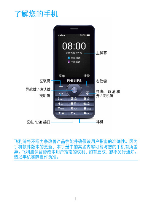
了解您的手机飞利浦将不断力争改善产品性能并确保该用户指南的准确性。
因为手机软件版本的更新,本手册中的某些内容可能与您的手机有所差异。
飞利浦保留修改本用户指南的权利,如有更改,恕不另行通知。
请以手机实际操作为准。
主屏幕耳机右软键挂断、取消和开/关机键左软键导航键/确认键接听键充电/USB 接口待机屏待机屏由以下部分组成:按键了解主要按键如何操作。
功能(拨号拨打或接听电话。
,确认及导航键选择或确认菜单功能。
)挂机/退出/开关机结束通话; 返回待机屏;长按开启/关闭手机。
L 左软键选取屏幕上的对应选项。
R右软键选取屏幕上的对应选项。
*键盘锁在待机屏,长按*锁定键盘;或先按L ,再按* 锁定键盘或为键盘 解锁。
图标行快捷菜单图标与符号了解显示屏上显示的图标。
静音来电时手机会静音。
振动来电时手机会振动。
电池指示条显示电量状态。
短信您收到一条新短信。
未接电话您有一个未接电话。
耳机耳机已接连到手机。
GSM网络手机已连接到GSM 网络。
指示条越多,接收质量越好。
GPRS连接手机已连接到GPRS网络。
第一次使用安装与充电首次使用手机时,如何安装SIM卡及给手机充电。
插入SIM卡234为电池充电新电池已部分充电,手机屏幕上的电池图标表示电量状态。
插入Micro SD卡(存储卡)提示:•充电时,您仍可以使用手机。
•电池完全充电后,将充电器继续连接在手机上不会损坏电池。
如需关闭充电器,应将其从电源上拔下。
因此,请选择易于您插拔的插座。
•如果您几天内都不会使用手机,建议您取出电池。
•如果已完全充电的电池搁置不用,电池本身在一段时间后,会因自放电而处于无电压或低电压状态。
•新电池或长时间未使用的电池,需要较长时间充电。
您可在手机中插入Micro SD卡以 扩展手机存储容量。
将Micro SD卡与卡槽对齐并放入卡槽。
使用您的手机如何拨打电话拨出电话1输入电话号码。
2按(拨打该号码。
3按)挂机。
提示:•如需拨打国际长途电话,长按0输入国际前缀“+”。
16位单通道USB数据采集卡使用说明
DAQCard-060101 16位单通道USB数据采集卡使用说明一、基本参数输入电压量程:±1V,±10V输入通道:单通道差分输入分辨率:16bit采样率:1ksps —500ksps软件可调。
二、硬件接口说明1、USB接口, 可直接插入计算机USB插口,或使用USB延长线。
2、差分电压信号输入端:“+”接差分信号正输入端,“-”接差分信号负输入端。
3、量程选择跳线:两个短路块同时插在外侧,选择±10V量程,同时插在内侧,选择±1V量程。
请勿将两个短路块插在不同的两侧。
三、驱动安装说明1、本卡通过USB接口供电和传输数据,支持即插即用和热插拔。
2、首次使用本卡时,需要安装驱动程序。
此后再使用时无须再次安装驱动,即插即用。
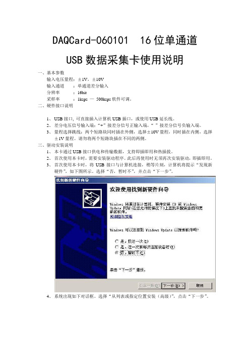
3、首次使用本卡时,将USB接口与计算机连接,稍等片刻,计算机将提示“发现新硬件”,如下图所示。
选择“否,暂时不”,并点击“下一步”。
4、系统出现如下对话框。
选择“从列表或指定位置安装(高级)”,点击“下一步”。
5、系统出现如下对话框。
选择“不要搜索。
我要自己选择安装的驱动程序”,点击下一步。
6、如出现下面的对话框,选择“通用串行总线控制器”,点击“下一步”。
7、系统出现如下对话框。
则点击“从磁盘安装”。
8、在弹出的路径对话框中选择程序安装目录下的“DAQCard-060101.Inf”文件。
点击“确定”。
9、回到6步所示对话框,此时出现提示“DAQCard(without driver)”,选中该项后,点击“下一步”。
10、系统开始安装驱动,若弹出如下对话框,选择“仍然继续”。
11、驱动安装完成,出现如下对话框,点击“完成”。
12、稍等片刻,系统再次提示安装驱动程序。
选择“否,暂时不”,点击“下一步”。
13、选择“自动安装软件”,点击“下一步”。
14、选中第二项驱动文件(如下图所示),点击“下一步”。
15、选择“仍然继续”。
16、驱动安装完成。
LMC2010_DIG_CUH_V2(1)_数字卡使用说明

北京金橙子科技有限公司电子文档
II
版权所有,复制必究
LMC2010 用户使用手册__DIG
目
录
安全须知...........................................................................................................................................1 1 概述...........................................................................................................................................2 1.1 数字卡的结构.................................................................................................................... 2 1.2 主要特点............................................................................................................................ 3 2 电气连接.......................................................................................................................................3 2.1 接口说明.............................................................................................................................3
IPG激光器控制卡使用说明书
USBLMC_CUH_IPG_V1(4)USBLMC Client Use HandbookIPG BoardCatalogSafety During Installation And Operation (1)Summarize (2)Ways to differentiate modules (3)I.Functions of Fiber Module(IPG)and Definitions of Pins (3)1.Features (4)2.Output Socket Definitions (4)3.Definition of Output Socket Pin (5)a.CON1:DB15Galvo Output (5)b.CON2:DB25Fibre socket (6)c.CON3:DB9Marking-on-fly Encoder (7)d.CON4:DB15Power (8)e.CON5:IDC10Socket (10)4.Jumper Illustration (11)5.Hardware Connection (13)a.Input signal IN0,IN8,Start,EMSTOP (13)b.Input signal IN5,IN9 (13)b.Power Connection (14)c.Typical Connection of Fiber Laser Module (16)II.The common connection ways (16)1.The connection between User-defined digital Galvo conversion board&USBLMC control card (16)2.The encoder,photoelectric switch during marking-on-fly (18)Safety During Installation And OperationPlease read these operating instruction completely before you proceed with installing and operating this product.If there are any questions regarding the contents of this manual,please contact BJJCZ.1.Steps For Safe Operation�Carefully check your application program before running it.Programming errors can cause a break down of the system.In this case neither the laser nor the scan head can becontrolled.�Protect the board from humidity,dust,corrosive vapors and mechanical stress.�For storage and operation,avoid electromagnetic fields and static electricity.These can damage the electronics on the product.For storage,always use the antistatic bag.�The allowed operating temperature range is25℃±10℃.�The storage temperature should be between–20℃and+60℃.ser Safety�This product is intended for controlling a laser scan system.Therefore all relevant laser safety directives must be known and applied before installation and operation.Thecustomer is solely responsible for ensuring the laser safety of the entire system.�All applicable laser safety directives must be adhered to.Safety regulation may differ from country to country.It is the responsibility of the customer to comply with all localregulations.�Please observe all laser safety instructions as described in you scan head or scan module manual,and this manual.�Always turn on the power of this product and the power supply for the scan head first before turning on the laser.Otherwise there is the danger of uncontrolleddeflection of the laser beam.We recommend the use of a shutter to prevent uncontrolled emission of laserradiation.SummarizeUSBLMC marking control card is developed specially for marking machine,it adopt USB interface BLMC marking control card is made up of two PCB board:Main-board and IO board.Main board and IO board are connected by two sockets which with50pins.The main-boards are the same,the IO board is divided into three different kinds by application:Optic fiber module(IPG),common digital module,and common analog module.Among them,common digital module is with a conversion board.Features of USBLMC�PowerUSBLMC marking control card uses5V power.We suggest adopt the power of5V/3Ato achieve power mon digital module,common analog interface’s powerinput signal is on CON2socket of module;and the power input signal of the optic fibermodule is on CON4socket of module.Please check the corresponding instruction ofPINS.�The laser Control1)Offer3routes TTL signal:Laser Gate,PWM,FPK for laser ser Gatesignal used for controlling switch of laser;PWM signal can be regarded as PWMsignal in CO2laser machine or the repeated pulse frequency in Nd:Yag lasermachine;FPK is for the first pulse inhibits signal in YAG laser machine.2)Offer2routes that are used for controlling the power of the laser power supply andrepeated pulse frequency of Q switch.3)As to the YLP series of pulse optic fiber laser machine of IPG,which is supplyspecial control signal.4)Laser Gate,PWM signal can be set up into high level available or low levelavailable.5)Common digital module,common analog module can be used for pre-setting theoutput power of the laser power supply.�Common digital input/output signal(TTL signal)There are10routes input and7routes output mon digital signal is dividedinto two kinds,switch form of input signal(no need external power)and non-switchform of input signal(external component entities supply the electric current drive).Common output signal is belong to TTL output(Without optical-isolation),the maxoutput electric current is15mA.Note:"The inputs/outputs signal"of this manual are all for USBLMC control card.The signals receiving by the USBLMC and driving by external component is inputsignals;signals driving by USBLMC control and receiving by external component isoutput signals.�Support multi-card working pattern.One computer can control8sets of USBLMC at a time,makes and marks the control board to run side by side and operate.Differentcontents can be processed by8sets of control cards.�Marking-on-flyFlying encoder can be connected to do real-time liner speed checking for good result ofhigh speed marking.�Extend axis(step motor/servo electrical motor)outputCan output two directions/pulse signals of channels to control step motor(or servoelectrical motor),applicable to pivot or join.�Start signalUsed when marking contents are the same and high speed is required.The Floor pushcan connect to Start signal,or to the common input signal as well.If there are variablesin marking content,they have to be connected to the common input signal.�Compatible with USB2.0/USB1.0Ways to differentiate modulesThere are some texts at the right-bottom corner of the er can differentiate them by them.The contents are:I.Functions of Fiber Module(IPG)and Definitions of PinsEach module is developed according the different applications.Therefore,its serial number,pin definition,jumper setting,and functional settings can vary.When in use please make sure to refer to the instructions of each particular type of module.For example,5V power input signal of USBLMC,on the common digital module and common analog module,should be inserted from12/13/24/25of the feet on CON2socket;while on the optic fiber module,the power input signal is connected from4/5/12/13of the feet on CON4 socket.1.Featuresa).Specially set for the YLP pulse laser by IPG Company.CON2-DB25pin is directlyconnected with the laser cube’s25-stitch pin.b).Digital IO signal,with1-way common output and3-way common input signals.IN0/IN1are fixed as the input at fiber laser status;IN6as the emergency-stop signal input for fiber laser.IN7is to check whether the power of laser marking machine is turned on or off;IN2/3/5are not applicable.IN4/8/9are comment input signals.For specific connections and the suggested connections,please see the section“Digital IO Connection Instructions”.OUT0is the common output;OUT2s fixed as the red light of fiber laser;OUT3is fixed as laser enabled.OUT1,and OUT4~6are not used.c).Output X-axis step motor to control signals.Y/Z axis cannot be output.d).Connect rotary encoder for high speed marking.e).Galvo output signals are digital outputs and can be set as non-encoded digital signal outputs,or set as digital signal outputs with extend codes.2.Output Socket DefinitionsFig.1-1Fiber Module–Socket Illustration3.Definition of Output Socket Pina.CON1:DB15Galvo OutputGalvo signals are digital signals which can be directly connected to digital Galvo.Digital galvo’s signals transfer protocols are not exactly the same,therefore,it should be confirmed which type of transfer protocols is used by the digital galvo.The company also provides transfer boards,which are analog boards transferred from digital.It can also be transferred analog signal outputs and connected to analog galvo.Fig.1-2CON1of Fiber IO boardPin No.Signal name Illustrations1,9CLK-/CLK+Clock signal.Difference output2,10SYNC-/SYNC+Synchronized signal.Difference output3,11XChannel-/XChannel+Digital signal of X axis galvo.Difference output4,12YChannel-/YChannel+Digital signal of Y axis galvo.Difference output5,13ZChannel-/ZChannel+Digital signal of Z axis galvo.Difference output6,14Status-/Status+The state feedback signal of Galvo.Difference input8,15Gnd The reference ground of control card.For the common two-dimension Galvo,only connecting CLK,SYNC XChannel,Ychannel four groups with8signal lines is enough.We suggest use twisted-pair(such as net-line)for connecting for digital signal.b.CON2CON2::DB25Fibre socketCON2socket and optic fiber25stitch socket of laser instrument connect through25stitch rows of line directly.Fig.1-3Pins of CON2Pins Signal name Illustrations1——8P0——P7Laser power.TTL output.9PLATCH Power latch signal.TTL output.10,14Gnd Control card’s Ground11,12Ver2:GND Control card’s Ground Ver3:SGIN2,SGIN3Laser status input.13,15,24Ver2:GND Control card’s Ground Ver3:NULL Reserved16,21SGIN4,SGIN1Laser status input.17Vcc5V power output of control card.18MO Master Oscillator switch.TTL output 19AP Power amplifier.TTL output.20PRR Repeat pulse power signal.TTL output.22Out2Laser’s red light indication signal.TTL output.23EMSTOP Emergency stop signal.TTL output. 25NULL Reservedc.CON3:DB9Marking-on-fly EncoderFig.1-4Pins of CON3PIN No.Signals Illustrations1IN8Common input signal8.Forms a return circuit with GND9. To use this signal,connect it and GND respectively to either terminals of power.2,6IN9+/IN9-TTL input signal.Internal1K current-limited resistor. External current-limited resistor is suggested when voltage is over12V.Please refer to IN9Port Illustration.3,7BCODEN/BCODEP Encoder phase B input signal.Differential input. 4,5ACODEN/ACODEP Encoder phase A input signal.Differential input. 8Vcc Control card5V output.9Gnd Control card Ground.As the return circuit signal of pin8& 1.d.CON4:DB15PowerFig.1-5Fiber Interfere Board CON4Socket Signals and the definitions PIN No.Signals Illustrations1SGIN0Common input signal0.Forms a return circuit with ground 12and13of the control board.To use this signal,connect it and the ground respectively to either terminal of the power.This is an input signal.2EMSTOP Emergency-stop signal.Forms a return circuit with ground 12&13.To use this signal,connect it and the ground signal respectively to either terminal of the NORM-OPEN switch.When this EMSTOP is pressed,it means there is emergency and operation is immediately stopped.The signal is an input signal.3Ver2:POW_BTN Power signal of the laser instrument main power source. Forms a return circuit with the Ground12&13of the control board.To use this signal,connect it and the Ground signal respectively to either terminal of the NORM-OPEN switch.When the power button is pressed downward,pin 10&11are connected;when the button is bounced upwards,they are disconnected.For the power connection, see“Power Connection”.This is an input signal.Ver3:NULL Reserved4,5VCC5V input power positive terminal.This is an input signal.8START Start signal.Forms a return circuit with Ground12&13. To use this signal,connect it and the Ground signal respectively to either terminal of the power.This is an input signal.9OUT0Common output es GND12&13signals as reference signals.This is an output signal.10,11Ver2:POW_CON,POW_CON1Connection port of power relay.Connect POW_CON to theanode of power relay’s control power.One of the powerrelay’s control ports should be connected withPOW_CON1,and the other to the cathode of the cathode ofpower relay’s control power.When the3-point power isplugged in,POW_CON and POW_CON1are connected.At that time,power relay’s control port is connected to itscontrol power,power relay picks up,and fiber laser mainpower is on.Please see“Power Connection”for reference. Ver3:NULL Reserved12,13Gnd 5V input power cathode(Ground signal),i.e.the control card’s Ground signal.This is an input signal.6,14DIR-/DIR+Output signal.Direction signal of the extend axis(step motor or servo motor).The output mode could be set up either as differential output,or as level output(TTL output).This is an output signal.7,15PUL-/PUL+Pulse signal of extend axis(step motor or servo motor). The output mode could be set up either as differential output,or as level output(TTL output).This is an output signal.e.CON5:IDC10SocketFig.1-6CON5Socket PIN No.Signals Illustrations 1,2,3,4OUT5/4/6/1Common output signal es GND 5&7signals as reference signals.This is an output signal.5,7GND Ground 6,8NULL Reserved 9,10S45GND,SGIN5Common input signal 5.4.Jumper IllustrationFig.1-7Illustration of Fiber Interface board Module Jumper Location See jumper illustration below:Label NO.IllustrationsJP1,JP23Extend axis direction/pulse signaling set up.JP1set direction,JP2set pulse signal.Short connection to pins 1-2of jumper will makedifferential output of direction/pulse signal.CON4’s DIR-,DIR+,PUL-,PUL+should be respectively connected to step drive’sDIR-,DIR+,PUL-,PUL+.Short connection to pins 2-3of jumperwill make level output of direction/pulse signal.In this case,CON4’s VCC 、DIR+、PUL+should be respectively connected tostep drive’s VCC,DIR,PUL.JP32If pin NO.3of CON4is not connected to power switch,thisjumper should be connected short.Here correspond to that thepower switch is push down always.For system that uses powerswitch,do not connect the jumper.JP42Not used.JP5,JP6,JP72Index numbers 0~7,used to differentiate various cards when manycards are working at a time.JP8-JP7-JP6correspond to binary b2,b1,b0.Short connecting JUMPER means b0,and not short connecting it means b1.JP92Short connecting the JUMPER means galvo data excludes expanded code(s).Not short connecting it means it contains expanded code(s).Default Settings:JP1~JP2:Short connecting pin2~3.Extend axis direction/pulse signals output level mode. JP3:Not connecting.JP4:Not connecting.JP5~7:Not connecting.JP9:Short connecting.Fig.1-8Fiber module(Fiber Laser Module)Jumper Default Settings5.Hardware Connectiona.Input signal IN0,IN8,Start,EMSTOPFig.1-9input interface SGIN0、IN8、Start and EMSTOPFig.1-110Recommended Connection for Common Input SignalOnly an external switch is needed,and the contact resistance of the switch should be under100Ω.b.Input signal IN5,IN9Common input signal IN9connection circuit and suggested connection are shown as in fig.1-11 and1-12.(CON5PIN10and PIN9for IN5)Fig.1-11Common Input Signal IN9connection Circuit IllustrationFig.1-12Recommended Connection for Common Input Signal IN9The external power supply needs proper input voltage to make sure the current is between 10mA ~15mA.When input voltage is over 12V,it is suggested that control carton connects current-limited resistor R1.Supposed the input current chosen is 12mA,then the input resistance R1is calculated as per the following formula:10001121×⎟⎠⎞⎜⎝⎛−=Vin R Ωb.Power ConnectionSee below fig.1-13for recommended power connection:Fig.1-13Recommended power connection wayWhen the power switch is on,the control card turns on the power relay,and the laser main power is connected to the fiber laser.Pin POW_CON and pin POW_CON1allow maximum current of500mA.c.Typical Connection of Fiber Laser ModuleFig.1-14Typical connection way of fiber interface boardFor the Floor push,it depends whether the rotary encoder needs connected.If the marking-on-fly function is not used,then there is no need to connect the rotary encoder.II.The common connection ways1.The connection between U ser-defined digital Galvo conversion board&USBLMC control cardCON1(Digital input signal socket):Connect User-defined digital Galvo conversion’s DB15with USBLMC control card’s DB15directly.Fig.3-1Connection of conversion boardCON2(Power socket):Connect the outside±15V power to the corresponding pin,the range of the voltage is[±12V—±15V],as the following figure(Fig.3-2)Fig.3-2Connection of Power supplyCON3/CON4(Galvo control signal):It’s divided into Single interface&Difference two connection ways,we should choose the most suitable connection way according the GalvoNote:Difference connectioninterface’’s.We suggest use connection’’s output voltage is twice of single interfacesingle interface connection.And while only confirmed the Galvo interface is Difference interface,we can consider to follow the Difference output way.The two connection ways are as following figure(Fig.3-3Single interface of Galvo;Fig.3-4The difference of Galvo)Fig.3-3Single interface of GalvoFig.3-4The difference of Galvo2.The encoder,photoelectric switch during marking-on-flyUSBLMC control card receives differential drive signal(eg DS26LS31type)of encoder;use CON3:DB9encoder and photoelectric switch socket of mark-on-fly.The connection as the following figure(Fig:3-5)Fig.3-5Connection of encoder and photoelectric switch。
打标卡 使用说明

8 套控制卡可以加工不同的内容。 扩展轴 (步进电机/伺服电机) 输出: 可输出两个通道的方向/脉冲信号控制步进电机 (或 伺服电机) ,可用于转轴或者拼接。 10 路通用输入数字信号(TTL 兼容) 。In0-In9。其中,In0-3 从 CON2 插座接入;In4-7 从 CON4 插座接入;In8/In9 从 CON3 插座接入 7 路通用输出数字信号 (TTL 兼容) 。 Out0-6。 其中, Out0-3 从 CON2 插座输出; Out14-6 从 CON4 插座输出 Start (开始) 信号: 用于打标内容相同, 要求高速打标的情况。 脚踏开关可以连接至 Start 信号,也可以连接至通用输入信号。如果打标内容含有变量文本,或者打标内容较多无 法全部保存在板卡中,必需连接至通用输入信号。 Laser 信号可设置可设为高电平有效,也可设为低电平有效 PWM 信号提供了差分驱动方式。 输出两路模拟量控制功率 / 频率。 兼容 USB2.0。
振镜控制信号为数字信号, 可以直接连接至数字振镜。 由于数字振镜所用的数字信号传 输协议不完全一样,所以,需要确认是数字振镜使用何种传输协议。我公司也提供了数字转 模拟的转接板,也可通过该转换板转成模拟信号输出连接到模拟振镜。
北京金橙子科技有限公司电子文档
3
版权所有,复制必究
USBLMC 用户使用手册
图 2-1 CON1 插座管脚定义示意图
管脚 1,9 2,10 3,11 4,12 5,13 6,14, 7 8,15
名称 CLK- / CLK+ SYNC- / SYNC+ X Channel- / X Channel+ Y Channel- / Y Channel+ Z Channel- / Z Channel+ Status-/Status+ NULL GND
LMC_CUH__PCI-E光纤卡使用说明

PCI-E-FIBER打标控制卡说明i版本记录版本号更新日期更新人更新说明V1.0 2015-06-29 PCIE打标控制卡目录须知 (1)1.1 如何辨识PCIE-FIBER打标控制卡 (2)1.2 主要特点 (3)二、电气连接 (3)2.1接口说明 (3)2.1.1 CON1 :CB15 振镜控制 (3)2.1.2 CON2 :DB25 激光控制 (5)2.1.3 CON3 :DB15 扩展轴与IO (7)2.1.4 CON4 :插头CON4与电脑主板USB的连接 (8)2.1.5 CON5 :DB9飞标接口 (9)2.1.6 LJQ5 :振镜,扩展轴,IO连接线 (10)2.2跳线说明 (11)2.2.1拨码开关SW1 (12)2.3 数字输入输出信号的连接 (12)2.3.1输入信号In0---In9,START (12)2.3.2输出信号Out6,Out7 (13)安全须知在安装、使用PCIE-FIBER控制卡之前,请仔细阅读本节内容。
若有任何关于本文档的疑问,请联系BJJCZ。
1.安全操作步骤z请遵守所有的关于激光的安全说明(包括但不仅限于描述于激光器、振镜以及本文档中的相关章节)z无论任何时候,请在开启了电脑电源、及振镜电源之后再打开激光器电源。
否则,可能会因不可控的激光光束而造成伤害。
我们建议您使用光闸来避免不可控的激光造成的伤害。
2.客户负责的安全部分z PCIE-FIBER被设计用来控制一个激光扫描系统。
因此,所有有关激光系统的安全指示都应该被客户了解并施行。
客户必须严格遵守相关的安全操作指示并独立地负责所用的激光系统的安全。
z安全规则可能因国家不同而有所差异。
客户有责任遵守当地的所有规定。
z在运行软件之前请仔细检查。
软件错误有可能导致系统停止响应。
在此情况下,振镜及激光均不可控制。
z请避免板卡受到潮湿、灰尘、腐蚀物及外物撞击的损坏。
z在储存及使用板卡时,请避免电磁场及静电的损坏。
USB视频采集卡使用说明书
其余三个 口均不接
2.测试线和采集卡的连接方法 测试线莲花头一端接在 USB 视频采集卡的黄色端子,另一端有 2 头
出线,分别是信号线(接 VTO)和地线,注意:测试线有 2 个出头,连 接时需要用万用表测一下导通;其中和莲花头外壳导通的接 GND,和 莲花头中心导通的接 VTO。
产品特性
◎ 支持 USB2.0,无需打开机箱,支持热插拔,支持笔记本电脑 ◎ 自行调整画面大小、最高分辨率可达 720×576,24 位真彩色 ◎ 最新技术 USB AUDIO、立体声输入输出 ◎ 图像亮度、对比度、饱和度、色度可自定义 ◎ 可捕捉高品质动态及静态画面,采集画面顺畅不间断 ◎ 输入接口有 AV 及 S 端子,可在台式机或手提电脑上观看录像、VCD、 DVD、摄像机等设备输出的视频影象 ◎ 支持 MPEG1/2 等多种实时压缩格式,方便制作 VCD/SVCD/DVD ◎ 兼容 WINDOW XP/Win7,兼容 Direct8.1、9.0
即在属性对话框中的 Image 标签下,选择“PAL/M”和“组合”选项, 确定后,即可在显示区看到摄像头图像了;如果此时还没有图像显示, 请调到第二步检查电气连接是否正确。
2.《USB 视频采集卡-Win7 版》
第一步 打开文件包,点击 Setup,进行软件安装。一直点击下 一步进行安装。
安装完成后,在桌面上回生成如下图所示的图标
插好 USB 视频采集卡,打开软件。如果 USB 视频采集卡没有插好, 或者 USB 口驱动电流不足,或者 USB 口接触松动,打开软件的时候会 出现以下错误:
更换 USB 口或者重新拔插几次,就可以打开软件了。如果重复几 次不可以打开软件,那么重新启动系统或者调到第三步重新安装软件 和驱动。
usb数据采集卡使用说明书V2.0
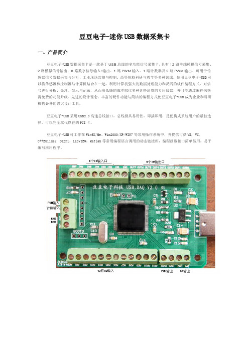
豆豆电子-迷你USB数据采集卡一、产品简介豆豆电子-USB数据采集卡是一款基于USB总线的多功能信号采集卡,具有12路单端模拟信号采集、2路模拟信号输出、8路数字信号输入/输出、1路PWM输入、1路计数器及2路PWM输出。
可用于传感器信号数据采集与分析、工业现场监测与控制、高等院校科研与教学等多种领域。
使用豆豆电子-USB可以将传感器和控制器与计算机结合在一起,利用计算机强大的数据处理能力和灵活的软件编程方式,对信号进行分析、处理、显示与记录,从而用低廉的成本取代多种价格昂贵的专用仪器,并且能通过编程来获得免费的功能升级。
先进的设计理念、丰富的硬件功能与简洁的编程方式使豆豆电子-USB成为企业和科研机构必备的强大设计工具。
豆豆电子-USB采用USB2.0高速总线接口,总线极具易用性,即插即用,是便携式系统用户的最佳选择,可以完全取代以往的PCI卡。
豆豆电子-USB可工作在Win9X/Me、Win2000/XP/WIN7等常用操作系统中,并提供可供VB, VC,C++Builder, Dephi,LabVIEW,Matlab等常用编程语言调用的动态链接库,编程函数接口简单易用,易于编写应用程序。
单位:mm二、性能指标2.1、USB总线性能●USB2.0高速总线传输●使用方便,能够实现自动配置,支持设备的热插拔即插即用2.2、模拟信号输入●模拟输入通道: 12路单端●输入端口耐压: 0—3.3V●输入信号量程: 0—3.3V●模拟输入阻抗: 10M●分辨率: 12Bit(4096)●最大总误差: < 0.2%●采样时钟: 100sps-100Ksps内部时钟(多通道50K)2.3、模拟信号输出●模拟输出通道: 2路单端(同步)●模拟输出范围: 0-3.3V●模拟输出电流: 1毫安●分辨率: 12Bit(4096)●非线性误差: ±2LSB●扫描时钟: 1sps-1000Ksps内部时钟2.4、数字信号输入/输出●输入/输出通道: 8路●输入/输出模式: 全输入/全输出●输入电平: 兼容TTL或CMOS●输出电平: CMOS2.5、PWM测量输入●个数: 1●输入电压: 0-3.3V●输入频率: 1—1MHz●输入占空比: 1%--99%●频率及占空比测量误差:1%2.6、计数器●计数器个数: 1●输入电平: TTL或CMOS●计数位: 32位(最大65535*65535)2.7、PWM输出●PWM输出通道: 2●PWM输出电平: CMOS●输入占空比:1%--99%●输出频率:1—1MHz2.8、工作温度●0℃ - 70℃三、应用领域便携式仪表和测试设备传感器信号采集与分析工业控制四、软件支持提供Windows95/98/NT/2000/XP/WINDOWS 7(32bit)下的驱动程序,提供通用DLL文件,并提供在LabVIEW和LabWindows图像化语言编写的应用软件范例程序。
富士通瘦身手机USB数字电视机顶盒说明书
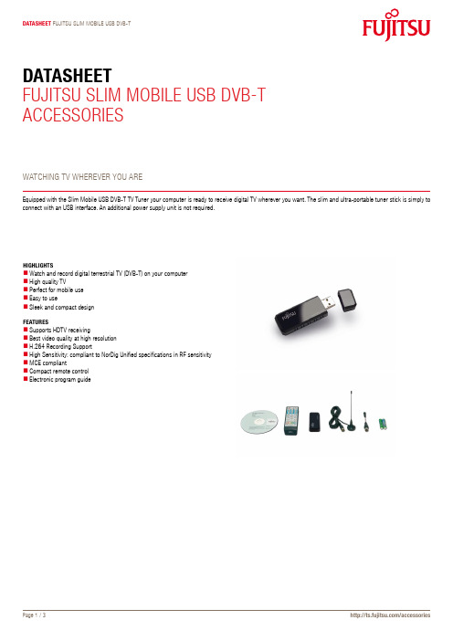
Datasheet Fujitsu slim mobile usb DVb-tDatasheetFujitsu slim mobile usb DVb-tAccessoriesWAtching tV WhereVer you Areequipped with the slim mobile usb DVb-t tV tuner your computer is ready to receive digital tV wherever you want. the slim and ultra-portable tuner stick is simply to connect with an usb interface. An additional power supply unit is not required.highlightsWatch and record digital terrestrial tV (DVb-t) on your computerhigh quality tVPerfect for mobile useeasy to usesleek and compact designFeaturessupports hDtV receivingbest video quality at high resolutionh.264 recording supportHigh Sensitivity: compliant to NorDig Unified specifications in RF sensitivitymce compliantcompact remote controlelectronic program guideslim mobile usb DVb-ttechnical speciFicationsInput Signal: 75 Ω TVAntenna inputbandwidth: 6/7/8 mhzNorDig Support – compliant to NorDig Unifiedspecifications in RF sensitivityFeatures and functions experience the best in digital home with microsoft Windows XP / XP mce 2005 / VistaDigital subtitle supportPicture-in-Picture (PiP) / Picture-out-of-Picture (PoP)Powerful channel scan capabilityePg (electronic Program guide)mheg-5 support (uK Digital teletext service)Wake up recording from stand by (s3) / hibernate (s4) moderecord tV programs in mPeg-2 formatrequired interface usb 2.0color piano blacksystem requirementsFor timeshift and record in mPeg-2:intel® Pentium® 4 2.4 ghz (hyper-threading)AmD Athlon™ XP 2400+intel® Pentium® mobile 1.3ghzmin. VgA card supports DirectX 9.0cmin. 256 mb rAmmin. 200 mb available free disk spaceFree usb 2.0 Portsound cardmicrosoft Windows® XP / XP mce 2005 / Vista®For hDtV (mePg-2) only:VgA card supports DirectX 9.0c and DXVA (hDtV)hDtV will only function when the tV signal is inhDtV formatFor h.264 recording (sDtV) only: Pentium 4 2.8 ghz (hyper-threading) or equivalent required interface usb 2.0software support (operating system)microsoft® Windows® XPmicrosoft® Windows® XP media center edition 2005microsoft® Windows® Vistacomplianceeurope cecompliance link https:///sites/certificates/default.aspxDimensions / WeightDimensions (W x D x h)70 x 25 x 11 mmWeight17.5 gpackage content1 x slim mobile usb DVb-tinstallation cDQuick installation guiderF cableAntennaremote control (1 set of batteries included)safety bookletHelpdesk flyerorDer inFormations26391-F7125-l1 / eAn: 4333643169657contactFujitsu technology solutions Website: 2010-04-01 ce-enproject for reducing burdens on the environment.using our global know-how, we aim to resolveissues of environmental energy efficiencythrough it.Please find further information at http://www./global/about/environment/delivery subject to availability. Any liability thatthe data and illustrations are complete, actualor correct is excluded. Designations may betrademarks and/or copyrights of the respectivemanufacturer, the use of which by third partiesfor their own purposes may infringe the rights ofsuch owner。
外部存储卡使用指南 说明书
External Media Cards Document Part Number: 406854-001April 2006This guide explains how to use external media cards with the computer.Contents1Digital Media Slot cardsInserting a digital card . . . . . . . . . . . . . . . . . . . . . . . . . . . 1–2 Stopping or removing a digital card. . . . . . . . . . . . . . . . . 1–3 2PC CardsConfiguring a PC Card. . . . . . . . . . . . . . . . . . . . . . . . . . . 2–1 Inserting a PC Card . . . . . . . . . . . . . . . . . . . . . . . . . . . . . 2–2 Stopping or removing a PC Card. . . . . . . . . . . . . . . . . . . 2–4 3Smart cardsInserting a smart card. . . . . . . . . . . . . . . . . . . . . . . . . . . . 3–2 Removing a smart card. . . . . . . . . . . . . . . . . . . . . . . . . . . 3–31 Digital Media Slot cards Optional digital cards provide secure data storage and convenient data sharing. These cards are often used withdigital-media-equipped cameras and PDAs, as well as with other computers.The Digital Media Slot supports the following digital cardformats:■Secure Digital (SD) Memory Card■MultiMediaCard (MMC)ÄCAUTION: To avoid damaging the digital card or the computer, do not insert any type of adapter into the Digital Media Slot.Digital Media Slot cardsInserting a digital cardÄCAUTION: To prevent damage to the digital card connectors, use minimal force to insert a digital card.To insert a digital card:1.Hold the digital card label-side up, with the connectors facingthe computer.2.Gently slide the card into the Digital Media Slot until the cardis seated.The operating system will issue a sound to indicate that adevice has been detected.✎The first time you insert a digital card, the “Found NewHardware” message is displayed in the notification area, atthe far right of the taskbar.Digital Media Slot cards Stopping or removing a digital card ÄCAUTION: To prevent loss of information or an unresponsive system, stop the digital card before removing it.To stop or remove a digital card:1.Close all files and applications that are associated with thedigital card.✎To stop data transfer, click Cancel in the operating systemCopying window.2.To stop the digital card:a.Double-click the Safely Remove Hardware icon in thenotification area, at the far right of the taskbar.✎To display the Safely Remove Hardware icon, click theShow Hidden Icons icon (< or <<) in the notificationarea.b.Click the digital card listing.c.Click Stop.Digital Media Slot cards3.Press in on the digital card 1 to release it, and then removethe card from the slot 2.2PC CardsA PC Card is a credit card–sized accessory designed to conformto the standard specifications of the Personal Computer MemoryCard International Association (PCMCIA). The PC Card slotsupports■32-bit (CardBus) and 16-bit PC Cards.■Type I or Type II PC cards.✎Zoomed video PC Cards and 12-V PC Cards are not supported. Configuring a PC CardÄCAUTION: To prevent loss of support for other PC Cards, install only the software required for the device. If you are instructed by the PC Cardmanufacturer to install device drivers:■Install only the device drivers for your operating system.■Do not install any other software, such as card services, socket services, or enablers, supplied by the PC Card manufacturer.PC CardsInserting a PC CardÄCAUTION: To prevent damage to the computer and external media cards, do not insert an ExpressCard into a PC Card slot or a PC Card intoan ExpressCard slot.To prevent damage to the connectors:■Use minimal force to insert a PC Card.■Do not move or transport the computer when a PC Card is in use.The PC Card slot may contain a protective insert. The insert mustbe released and then removed before you can insert a PC Card.1.To release and remove the PC Card slot insert:a.Press the PC Card eject button 1.This action extends the button into position for releasingthe insert.b.Press the eject button again to release the insert.c.Pull the insert out of the slot 2.PC Cards2.To insert a PC Card:a.Hold the PC Card label-side up, with the connector facingthe computer.b.Gently slide the card into the PC Card slot until the card isseated.The operating system will issue a sound to indicate that a device has been detected.✎The first time you insert a PC Card, the “Found New Hardware” message is displayed in the notificationarea, at the far right of the taskbar.PC CardsStopping or removing a PC CardÄCAUTION: To prevent loss of information or an unresponsive system, stop a PC Card before removing it.✎An inserted PC Card uses power even when idle. To conserve power, stop or remove a PC Card when it is not in use.To stop or remove a PC Card:1.Close all applications and complete all activities that areassociated with the PC Card.✎To stop data transfer, click Cancel in the operating systemCopying window.2.To stop the PC Card:a.Double-click the Safely Remove Hardware icon in thenotification area, at the far right of the taskbar.✎To display the Safely Remove Hardware icon, clickthe Show Hidden Icons icon (< or <<) in thenotification area.b.Click the PC Card listing.c.Click Stop.PC Cards3.To remove the PC Card:a.Press the PC Card slot eject button 1.This action extends the button into position for releasingthe PC Card.b.Press the eject button again to release the PC Card.c.Pull the card 2 out of the slot.3Smart cards✎The term smart card is used throughout this chapter to refer to both smart cards and Java™ Cards.A smart card is a credit card–sized accessory that carries amicrochip containing memory and a microprocessor. Likepersonal computers, smart cards have an operating system tomanage input and output, and they include security features toprotect against tampering. Industry-standard smart cards are used with the smart card reader.A personal identification number (PIN) is needed to gain accessto the contents of the microchip. For more information aboutsmart card security features, refer to the Help and Support Center.Smart cardsInserting a smart cardTo insert a smart card:1.Holding the smart card label-side up, gently slide the cardinto the smart card reader slot until the card is seated.2.Follow the on-screen instructions for logging on to thecomputer using the smart card PIN.Smart cards Removing a smart cardTo remove a smart card:»Grasp the edge of the smart card and pull it out of the smart card reader.© Copyright 2006 Hewlett-Packard Development Company, L.P.SD Logo is a trademark of its proprietor. Java is a trademark of Sun Microsystems, Inc.The information contained herein is subject to change without notice. The only warranties for HP products and services are set forth in the express warranty statements accompanying such products and services. Nothing herein should be construed as constituting an additional warranty. HP shall not be liable for technical or editorial errors or omissions contained herein.External Media CardsFirst Edition: April 2006Document Part Number: 406854-001。
- 1、下载文档前请自行甄别文档内容的完整性,平台不提供额外的编辑、内容补充、找答案等附加服务。
- 2、"仅部分预览"的文档,不可在线预览部分如存在完整性等问题,可反馈申请退款(可完整预览的文档不适用该条件!)。
- 3、如文档侵犯您的权益,请联系客服反馈,我们会尽快为您处理(人工客服工作时间:9:00-18:30)。
图 2
1 CON1 插座管脚定义示意图
管脚 1 ,9 2,10 3,11 4,12 5,13 6,14, 7 8,15
名称 CLK- / CLK+ SYNC- / SYNC+ X Channel- / X Channel+ Y Channel- / Y Channel+ Z Channel- / Z Channel+ Status-/Status+ NULL GND
2.4 典型连接.......................................................................................................................... 15
北京金橙子科技有限公司电子文档
III
版权所有,复制必究
USBLMC 用户使用手册
安全须知
在安装、使用 USBLMC 控制卡之前,请仔细阅读本节内容。若有任何关于本文档的疑 问,请联系 BJJCZ。 1. 安全操作步骤 � 请遵守所有的关于激光的安全说明 (包括但不仅限于描述于激光器、 振镜以及 本文档中的相关章节) � 无论任何时候,请在开启了电脑电源、USBLMC 电源及振镜电源之后再打开 激光器电源。否则,可能会因不可控的激光光束而造成伤害。 我们建议您使用光闸来避免不可控的激光造成的伤害。 2. 客户负责的安全部分 � USBLMC 被设计用来控制一个激光扫描系统。因此,所有有关激光系统的安 全指示都应该被客户了解并施行。 客户必须严格遵守相关的安全操作指示并独 立地负责所用的激光系统的安全。 � 安全规则可能因国家不同而有所差异。客户有责任遵守当地的所有规定。 � 在运行软件之前请仔细检查。 软件错误有可能导致系统停止响应。 在此情况下, 振镜及激光均不可控制。 � 请避免板卡受到潮湿、灰尘、腐蚀物及外物撞击的损坏。 � 在储存及使用板卡时, 请避免电磁场及静电的损坏。 它们有可能损毁板卡上的 电子器件。 请使用防静电包装袋储存板卡; 请佩戴接地良好的防静电防护手套 接触板卡。 � 请保证板卡储存在摄氏 -20℃至+60℃的环境下。允许的工作环境温度为 25℃ ±10℃。
北京金橙子科技有限公司电子文档
2
版权所有,复制必究
USBLMC 用户使用手册
1.2 主要特点
� � � � � � � 振镜控制信号为数字信号,可直接连接国际上通用的数字振镜。 飞行打标:可连接旋转编码器,实时检测流水线的速度,保证高速打标效果。 支持单机多卡工作模式。一台电脑可以同时控制 8 套 USBLMC 打标控制卡并行操作。 8 套控制卡可以加工不同的内容。 扩展轴 (步进电机/伺服电机) 输出: 可输出两个通道的方向/脉冲信号控制步进电机 (或 伺服电机) ,可用于转轴或者拼接。 10 路通用输入数字信号(TTL 兼容) 。In0-In9。其中,In0-3 从 CON2 插座接入;In4-7 从 CON4 插座接入;In8/In9 从 CON3 插座接入 7 路通用输出数字信号 (TTL 兼容) 。 Out0-6。 其中, Out0-3 从 CON2 插座输出; Out14-6 从 CON4 插座输出 Start (开始)信号: 用于打标内容相同, 要求高速打标的情况。 脚踏开关可以连接至 Start 信号,也可以连接至通用输入信号。如果打标内容含有变量文本,或者打标内容较多无 法全部保存在板卡中,必需连接至通用输入信号。 Laser 信号可设置可设为高电平有效,也可设为低电平有效 PWM 信号提供了差分驱动方式。 输出两路模拟量控制功率 / 频率。 兼容 USB2.0。
USBLMC_CUH_DIGIT_V1(2)
USBLMC 数字卡用户使用手册
USBLMC 用户使用手册
版本记录 版本号 V1.0 V1.1 V1.2 更新日期 2007-1 2007-6 2008-5-21 吕文杰 重新整理成单独的文档 更新人 更新说明
北京金版权所有,复制必究
说明 时钟信号- / 时钟信号+ 同步信号- / 同步信号+ 振镜 X 信号- / 振镜 X 信号+ 振镜 Y 信号- /振镜 Y 信号+ 振镜 Z 信号- /振镜 Z 信号+ 保留 保留 地
对于常用的二维振镜,只需要连接 CLK 时钟、SYNC 同步、XChannel、Ychannel 四 组信号共八根信号线即可。数字信号建议采用带屏蔽层的双绞线连接。
2.2 跳线说明............................................................................................................................ 8 2.3 数字输入输出信号的连接................................................................................................ 9
2.1.1 电源................................................................................................................................................ 3 2.1.2 CON1 :DB15 振镜控制.............................................................................................................3 2.1.3 CON2 :DB25 电源/激光/IO 控制..............................................................................................5 2.1.4 CON3 :DB9 飞标接口...............................................................................................................6 2.1.5 CON4 :DB15 IO 插座................................................................................................................7
USBLMC 用户使用手册
目
录
安全须知...........................................................................................................................................1 1 概述...........................................................................................................................................2 1.1 数字卡的结构.................................................................................................................... 2 1.2 主要特点............................................................................................................................ 2 2 电气连接.......................................................................................................................................3 2.1 接口说明............................................................................................................................. 3
� � � �
2 电气连接
2.1 接口说明 2.1.1 电源
控制卡需要 5V 直流电源供电。建议采用 5V/3A 的直流电源。电源从 CON2 插座的 12/24/13/25 管脚接入。 CON2 管脚 12, 24 13,25 名称 VCC GND 说明 +5V。电源的正极性端。 地。电源的负极性端。
2.3.1 输入信号 In0-3,In8, Start.......................................................................................................... 9 2.3.2 输入信号 In4-7,In9..................................................................................................................10 2.3.3 PWM 信号连接........................................................................................................................... 11 2.3.4 首脉冲抑制信号..........................................................................................................................13
