ARC160图纸
阿特拉斯GA132-160vsd产品样本
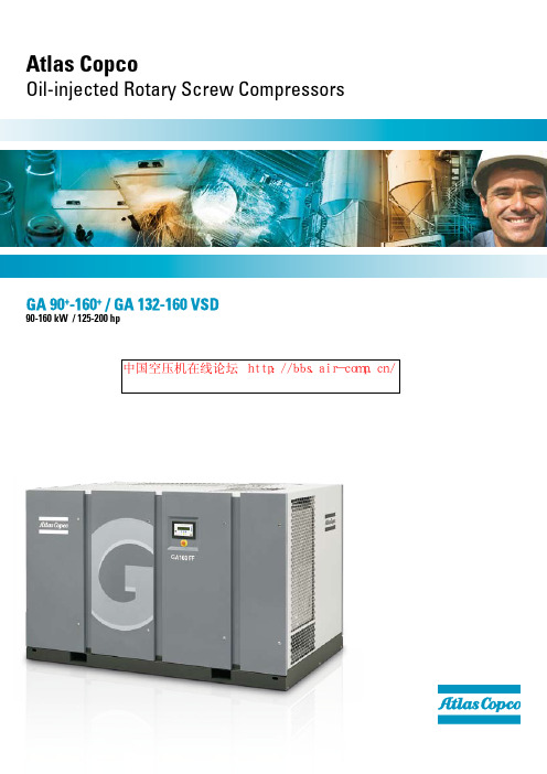
GA 90+-160+ / GA 132-160 VSD90-160 kW / 125-200 hpAtlas CopcoOil-injected Rotary Screw CompressorsWe are committed to your superior productivity through interaction and innovation.Total capability,total responsibilityRight at the heart of your business, Atlas Copco delivers quality compressed air for superior operational capacity. From compressed air generation to point of use, you can choose from our wide range of products to create a complete compressed air system tailored to your specific needs. All Atlas Copco products are engineered to integrate seamlessly, ensuring the highest level of reliability and energy efficiency. As a result, Atlas Copco can take full responsibility for your compressed air infrastructure with a guarantee of best-in-class quality. With a global presence in over 150 countries, we can provide an unrivalled service to maintain and continually improve your compressed air system performance.Backed by 100 years at the forefront of compressed air, Atlas Copco products offer the finest quality and efficiency. Our goal is to be First in Mind—First in Choice ®. That is why Atlas Copco’s pursuit of innovation never ceases, driven by the dedication to meet and exceed your demands. Always working with you, we are committed to providing the customized air solution that is the driving force behind your business.First in Mind—First in Choice 中国空压机在线论坛http://bbs.air-comp.cn/Powerful efficiencyDRIVING DOWN ENERGY COSTSThe cost of compressed air can represent over 40% of your total electrical costs. The GA compressor range achieves a new standard in energy efficiency, helping you spend less. With the addition of VSD (Variable Speed Drive) you can reduce costs by an additional average of 35%. By tuning compressor capacity to fluctuating air demand we can also reduce overall compressor lifecycle costs (LCC) by an average of 22%. The impact on the environment is considerable, reflecting Atlas Copco’s commitment to a safe, healthy world for future generations.BUILT TO LASTEvery GA is designed, manufactured and tested to comply with ISO 9001, ISO 14001 and ISO 1217 stipulations. It uses the latest generation of Atlas Copco’s patented oil-injected screw element, ensuring a long and trouble-free life at the lowest possible operating cost. Engineered for reliable service, even in ambient temperatures up to 55°C/131°F and very harsh environmental circumstances, the GA takes reliability to a new level.PROTECTING YOUR PRODUCTIONClean dry air expands the lifetime of your equipment and protects your investment. The new built-in refrigerant dryer ensures a lower dew point, which is reflected in higher efficiency.FOLLOW-UPTailored service contracts and state-of-the-art add-ons make sure you get the right maintenance, immediate response and genuine spare parts – anywhere in the world.TAILORINGAt Atlas Copco we offer the industry’s broadest portfolio of offerings to help you achieve the most efficient compressed air system for your needs, and optimize your production process at the same time.CHOICEAtlas Copco masters every principle of your air system and offers the most energy-efficient solution for each application.EASY INSTALLATION AND MAINTENANCEGA compressors are delivered ready to use and designed for trouble-free maintenance. The oil and air filters are easily accessible and cooler cleaning procedures are simple. The GA Full Feature (FF) compressor range with its integrated air treatment equipment reduces your installation costs even further, and leaves you the space you need for your application to run.TOTAL CONTROLFrom the Elektronikon ® compressor controller to the ES compressor room controller, Atlas Copco uses the most advanced algorithms designed to reduce your energy costs and ensure your peace of mind by keeping reliability at the maximum level.Efficient, reliable and built to last, the GA 90+-160+ / GA 132-160 VSD compressors are designed to provide high quality compressed air even under harsh conditions. Thanks to Atlas Copco’s Beyond a superior screw elementDRIVING DOWN ENERGY COSTS• The GA Series’ superior screw elements are designed to give the optimum combination of maximum free air delivery for low energy consumption.• The state-of-the-art compressor element is powered by Efficiency 1 class / NEMA EPAct electric motors, contributing to maximum compressor package efficiency.• GA VSD (Variable Speed Drive) compressors automatically adjust the compressed air supply to the demand. Thus the considerable waste of energy caused by no load operation and oil vessel blow-off losses can be avoided.• The VSD-driven radial cooling fans deliver optimum cooling flow and reduced energy consumption in any conditions, through precise fan speed regulation.• The optional Energy Recovery system can recover up to 94% of the compressor shaft power as hot water.• GA 90+-160+ / GA 132-160 VSD compressors feature no-loss drains, which eliminate the waste of compressed air that conventional drains create.• The integrated compressed air treatment includes a refrigerant dryer with the built-in Atlas Copco Patented Saver Cycle Control mode that reduces energy consumption in light load conditions.PROTECTING YOUR PRODUCTION• The aftercooler with integrated water separator immediately removes 100% of the condensate, delivering a higher quality of air than conventional external separators with typically low efficiencies (40-90%). This protects the downstream equipment from corrosion and water damage.• Thanks to Elektronikon-controlled drains, there is no risk of condensate building up and no risk of water suspended in the compressed air.• The GA’s integrated compressed air treatment (refrigerant dryer and compressed air filter) increases the quality of your end product by removing moisture, aerosols and dirt particles.BUILT TO LAST• The GA series’ superior screw element’s patented asymmetric rotor profile and meticulous bearing selection ensure low wear and tear and increased reliability.• All compressors feature TEFC IP55 motors designed for continuous operation under severe ambient temperature conditions up to 55°C / 131°F*.• The heavy duty air inlet filter works with a 2-step dust separation system, which protects the compressor components from wear, even in the dustiest environments.• The GA VSD (Variable Speed Drive) motors have been designed specifically to operate ideally during flexible air demands. The special motor design includes protection against bearing currents and optimizes motor cooling at lower speeds.• The GA VSD frequency converters feature epoxy coated electronic cards, and a heavy duty cooling air filtration is available as an option for operation under the dustiest environments.* Standard up to 46°C / 115°F. (Optional up to 55°C / 131°F)long-standing experience and pioneering innovations there’s a GA compressor available to cut costs and enable smooth, continuous operation right across your production processes.LOW MAINTENANCE COSTS• The heavy duty air inlet filter features a pre-separation cyclone which reduces the dust load in the fine filter doubling the filter element lifetime without reducing filter efficiency.• The high efficiency air/oil separation system consists of a 2-step separation system providing low residual oil content in the compressed air. Low oil consumption ensures low maintenance costs and longer up time.• The VSD radial cooling fans are maintenance-free with bearings greased for life.• Condensate is constantly removed from the water drains.A large diameter drain port removes the potential for clogging, providing trouble-free operation and minimal maintenance.• Replacement of the heavy duty oil filter is simple and quick.• For extended service intervals 8,000-hour oil filters are included as standard.• A mobile phone messaging option facilitates easy planning of routine maintenance activities. Efficient maintenance practices reduce the maintenance costs and ensure optimal compressor performance.ENVIRONMENTALL Y RESPONSIBLE• The VSD radial cooling fans and strong sound insulation reduce noise emissions to less than 71 db (A).• The Variable Speed Drive automation and instrumentation comply with 89/336/EEC directives and operate without any risk of electromagnetic interference.• VSD reduces electricity consumption by an average of 35%, enabling companies to become more independent of electricity supplies and reducing harmful CO2emissions.• The Energy Recovery system recycles energy back into hot water and air which can be used elsewhere in the production environment.LOWERED INSTALLATION COSTS• Totally assembled compressor package. No need to assemble loose shipped components. Simply connect a power supply, compressed air piping, and cooling water piping (for the water cooled version) and the compressor is ready to work.• The Full Feature concept comprises the total compressed air system compressor and air treatment equipment. It is all integrated inside the compressor canopy, limiting both installation costs and space requirements.A state-of-the-art integrated solution• The unique and patented Saver Cycle Control stops the dryer when the compressor is stopped or in unload mode, drastically reducing the power consumption. T he dew point is continuously monitored and the dryer is started again when the dew point starts to increase.• By adjusting the speed of the refrigerant compressor, the integrated VSD dryer control* provides maximum energy saving in low load conditions.• The dryers can perform at ambient conditions of up to 46°C / 115°F . High ambient temperature version available for temperatures up to 50ºC as an option.• Compressor and dryer are designed to work optimally together to perform smoothly under the most critical conditions.* GA VSD Full Feature onlyFEATURES OF THE ExTREME DUTY INTEGRATED REFRIGERANT DRYERINCREASE YOUR PRODUCTION RELIABILITYLow quality air heightens the risk of corrosion in your system, which can lower the life span of your air tools and production equipment. The GA’s filtration process produces clean air that enhances your system’s reliability, avoiding costly downtime and production delays.PROTECT THE ENVIRONMENTWith leaks and energy waste minimized and the unsafe disposal of untreated condensate eliminated, you can safeguard the environment and comply with stringent international regulations.INTEGRATED PURITYThe filters and integrated refrigerant-type air dryer (IFD) efficiently remove moisture, aerosols and dirt particles to protect your investment. This quality air expands the life of equipment, increasing efficiency and ensuring quality in your final product.SAFEGUARD YOUR PRODUCT QUALITYCompressed air coming into contact with your final products should not affect their quality. T he GA provides the clean, dry air that will protect your product’s reputation in the marketplace.DRIVING DOWN ENERGY COSTSClean, treated air reduces the risk of corrosion and leaks in your compressed air system. A 3 mm leak could easily add up to €1800 to your energy bill annually.Protecting your productionUntreated compressed air contains moisture, aerosols and dirt particles that can damage your air system and contaminate your end product. Resulting maintenance costs can far exceed air treatment costs. We believe in effective prevention.14 BAR 7 BARTotal control, assured efficiencyThe Elektronikon ® operating system provides monitoring to increase your compressor’s efficiency Easily expandable with extra sensors, digital inputs and internet communication functions, the Elektronikon can to your specific needs – offering simple, central and control of up to four compressors. For optimal ease of use, FULL Y OPTIMIZED SYSTEMThe ES Multiple compressors• Eliminating the inefficient transition period from full to no load power.• Avoiding excessive off load power consumption.• Maintaining the net pressure band within 0.10 bar, 1.5 psi.• Reducing overall average working pressure.• Minimizing system leakage due to a lower system pressure.• Increasing flexibility with soft starting gradual motor ramp-up to avoid electricity surges.• Offering flexible pressure selection from 3,5 to 14 bar with electronic gearing to ensure lowered electricity costs.With VSD (Variable Speed Drive) technology, air supply mirrors air usage – automatically adjusting the motor speed depending on demand. Lowered system pressure minimizes energyuse across all production processes to reduce energy costs. With VSD technology, Atlas Copco has made major energy savings a reality.VSD: Adapt to the flow, control your costsUsing innovative analysis technology, Atlas Copco engineers can map the fluctuations in demand in your current compressed air system and simulate the energy savings a VSD compressorcould bring to your production process. Ask your Atlas Copco representative for more information.THE GA VSD REDUCES ENERGY COSTS BY:JUST HOW MUCH CAN YOU SAVE?Driving down energy costsBecause there is no unnecessary power generated, the GA reduce energy costs by more. Lifecycle costs (LCC) of the compressor can be reduced by an average of 22%. In general, extra cost of a VSD compressor compared to a fixed speed one can be earned back after just one to two Traditional compressors with a full load, no control operate between set pressure points. maximum pressure is the compressor goes off During periods of medium to low air demand, the no load thE high PricE of fLUctUating DEmanDAir DemAnDenerGY CoSTStandard costsair Demand TimeVSD costsAir DemAnDTimeenerGY CoSTair Demand VSD: VariabLE VoLUmE, controLLED coStSLcc of a StanDarD comPrESSorinstallationmaintenance investment Energy consumption VSD comPrESSorinstallationmaintenance investment Energy consumption average 35% Energy Savings1234The Elektronikon ® system controls both the compressor and theintegrated converter; thus ensuring maximum machine safety as well as easy networking of the compressor.All Atlas Copco VSD compressors are EMC tested and certified.External sources do not influence the compressor operation, nor does the compressor affect the operation of other instruments via emissions or via the power supply line.Mechanical enhancements ensure that all the components operatebelow critical vibration levels within the complete compressor speed range.The frequency converter, low consumption, cooling fan ensuresstable operation even in high ambient temperatures up to 50°C / 122°F*INTEGRA TED VSD – THE SMART CHOICE• The machine is tested for the complete speed range to eliminate any ‘speed windows’ that could jeopardize the energy savings and the stable net pressure. (Turndown capability of the compressor is maximized to 80-85%.)• Special attention is given to the electric motor, which is specifically designed for VSD operation (inverter duty motor). Bearings are protected against induced bearing currents and both motor and converter are perfectly tuned to obtain the highest possible efficiency over the entire speed range.*Standard up to 46°C/114.8°F , optional high ambient version up to 50°C/122°F .SecondsmaximumFlowoperating rangemotor speedCombined motor/converter efficiency100 %1234WHAT ENERGY?Air compression creates heat that is normally wasted in the coolers. Atlas Copco-designed energy recovery systems enable the recovery of most of this heat. Recovery of energy from the shaft input of the compressor can be up to 94% of the compressor shaft power.WHY RECOVER ENERGY?Energy costs can constitute 80% of the total costs of compressed air production. With rising energy prices, saving energy also means a substantial cost saving .With global warming, Kyoto directives and the gradual depletion of traditional energy sources, every business has a duty to contribute as much as possible to overall energy conservation .HOW IS THE ENERGY RECOVERED?Energy recovery systems are integrated modules that recover heat which is otherwise wasted. The heat in the form of hot water (85-90 °C) is directly usable as a source of energy. The main module of the recovery system is built into the compressor.Shaft power100 %Radiant losses2 %Remaining heat in compressed airJul 04 Oct 04 Jan 05 Apr 05 Jul 05 Oct 05 Jan 06 Apr 06 Jul 06Date0.750.70.650.60.550.50.450.40.350.3P r i c e /l i t e r (€)evolution of the fuel oil prices (example from a european country)Maximize your savings…process water boilerHOW CAN THE RECOVERED ENERGY BE USED?The hot water generated can be put to several uses in the industry:• as preheated boiler feed water for industrial processes • for space heating by circulation in radiators or for showers • for other industrial applications like dyeing textiles, operation of absorption chillers, etc.The hot water produced should be used as an auxiliary source of energy, as the load of the compressor and thus the amount of heat produced may vary.HOW DO I BENEFIT?You save energy wherever energy as an auxiliary source to reduce your operating costs.The investment needed to link the hot oil circuit from the compressor to the existing water circuit is relatively modest and the time needed from your investment is generally very short.ASSUMPTIONS• example chosen is a 160 kW GA compressor• 8,000 running hours/year at full load and full energy recovery• cost of fuel oil: €0.55/l• figures shown are an example. Price calculations can Investment in energy recovery system is recovered in less than 2 months Compressor is paid back in less than 2 years Net gain of €570,000 in 10 years**Calculation only includes energy costs as maintenance will remain approximately the same as for a standard compressor.1570,00090,00060,00030,000S a v i n g s (€)Lifecycle costcentral heatingshowers…recover energyAt Atlas Copco, our responsibility doesn’t stop when the product is delivered. An extensive portfolio of exclusive Aftermarket products and services is designed to add maximum value for our customers – no hidden costs, no surprises and minimized risk to your processes. Guaranteed serviceability within 24 hours ensures optimum availability and reliability of your compressed air systems with the lowest possible operating costs. We deliver this complete service guarantee through our extensive Aftermarket organization, maintaining our position as the leader in compressed air.Peace of mindACTIVITY PRODUCT*Genuine parts Atlas Copco Service kits & oils Extended warranties AIRXtendService contracts ServicePlanSystem audits AIR Scan™Remote monitoring AIR Connect™Energy saving AIR Optimizer™Product improvements Upgrade programs* more information is available from your local atlas copco customer center.Complete scope suiting all needsIncluded as StandardHeavy duty Air inlet filter TEFC IP55 Class F electric motorAir intake flexible StartersAir intake valve (not on VSD units)Pre mounted electrical and VSD cubiclesCompressed air aftercooler and oil cooler Flexible vibration dumpersVSD cooling fans for air cooled units Air / oil separatorIntegrated water separator Elektronikon control systemElectronic water drains with no loss of compressed air Full load / no load regulation system (not for VSD)Heavy duty oil filters Silencing canopyComplete air, oil, water circuit Supression of emissions / harmonic distortionsOil containing structural skid with no need for foundations Stainless steel tube and Shell coolers for water cooled unitsAvailable options / Model GA 90+ - 160+GA 110 - 160GA 132 - 160 VSD Full Feature: integrated ID refrigerant dryer x x x Integrated DD pre-filter (only with integrated dryer)x x x Integrated energy recovery system x x x Separate air intake x x x Modulation Control x x N.A.High Ambient Version (up to 55 ºC / 131 ºF * )x x x Phase sequence relay x x standard** PT1000 T hermal protection in the main motor windings and bearings x x standard** Oversized main motor x N.A.N.A.Anti-condensation Heater in the main motor x x N.A.VSD cabinet heavy duty filtration (Applicable for VSDs)N.A.N.A.xNema 4 Cubicle x x N.A.Roto-Xtend Duty fluid 8000h x x xNPT connections x x x Anchor Pads x x x Performance test certificate x x x Witnessed performance test x x x Material Certificates x x x Seaworthy packaging x x xRain Protection Kit x x N.A.IT / NT network system x x xSPM vibration monitoring system x x xGSM alarm messaging system x x x Automatic water shut-off valve for water cooler units x x x Thermostatic water regulating valve N.A.N.A.x* GA Full feature 50 ºC / 122 ºF; GA VSD 50 ºC / 122 ºF; GA fix speed Pack 55 ºC / 131 ºF** Functionalities integrated in the frequency converter protectionsDimensionsCompressor typeAircooled Pack Aircooled Full Feature Watercooled Pack & Full Feature L W H L W H L W H mm inch mm inch mm inch mm inch mm inch mm inch mm inch mm inch mm inchGA 90+-160+260010220007920007932001262000792000792600102163064200079 GA 110-160260010220007920007932001262000792000792600102163264200079 GA 132-160 VSD320012620007920007938001502002792347923200126163064234792(1) Unit Performace Measured according to ISO 1217, Ed. 3, Annex C - 1996 faD is measured at the following working pressures- 5.5 bar variants at 5 bar- 7.5 bar variants at 7 bar(4) maximum working pressure for GA VSD - 8.5; 10;14 bar (e) / GA VSD FF - 8.3; 9.8 ; 13.8 bar(1) Unit Performace Measured according to ISO 1217, Ed. 3, Annex C - 1996 faD is measured at the following working pressures- 75 psi variants at 73 psi- 100 psi variants at 100 psi(4) maximum working pressure for GA VSD - 8.5; 10;14 bar (e) / GA VSD FF - 8.3; 9.8; 13.8 barIn order to be First in Mind—First in Choice ® for all your compressed air needs, Atlas Copco delivers the products and services that help increase your business’ efficiency and profitability.Atlas Copco’s pursuit of innovation never ceases, driven by your need for reliability and efficiency. Always working with you, we are committed to providing you the customized quality air solution that is the driving force behind your business.2935 0548 10 – P r i n t e d i n B e l g i u m – S u b j e c t t o a l t e r a t i o n w i t h o u t p r i o r n o t i c e .Never use compressed air as breathing air without prior purification in accordance with local legislation and standards.。
热带压机PM-609 160A-B 458的配件和图纸手册说明书
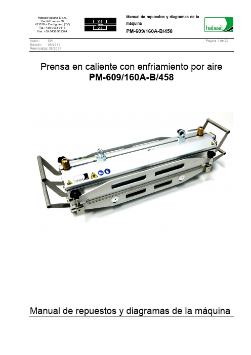
Autor:: MA Página1 de 24 Edición: 09/2011Reemplaza: 08/2011Prensa en caliente con enfriamiento por airePM-609/160A-B/458Manual de repuestos y diagramas de la máquinaAutor:: MA Página2 de 24 Edición: 09/2011Reemplaza: 08/2011ÍNDICE0PREFACIO (3)1IDENTIFICACIÓN DE LA MÁQUINA (4)1.1P LACA DE IDENTIFICACIÓN Y MARCA CE (4)2NORMAS Y ADVERTENCIAS GENERALES (7)2.1C RITERIOS DE ORGANIZACIÓN DEL MANUAL (7)2.2C RITERIOS DE USO DEL MANUAL (7)3ESPECIFICACIONES TÉCNICAS (9)3.1C ARACTERÍSTICAS ELÉCTRICAS (9)3.2C ARACTERÍSTICAS NEUMÁTICAS (9)3.3D IMENSIONES Y CARACTERÍSTICAS AMBIENTALES (9)3.4C ARACTERÍSTICAS DE PRODUCCIÓN (9)3.5D IMENSIONES (10)4PLANOS Y PIEZAS DE RECAMBIO (11)4.1H08D007262–G RUPO TRAVESAÑO SUPERIOR PRENSA (12)4.2H08D007264–G RUPO TRAVESAÑO INFERIOR PRENSA (14)4.3H08D007263–G RUPO UNIDAD DE CALENTAMIENTO (16)4.4H08D007261–G RUPO COJINES DE PRESIÓN (18)4.5H08D007265–G RUPO BARRAS DE BLOQUEO BANDA (19)4.6H08008E100–C ONEXIÓN NEUMÁTICA (21)5DIAGRAMA ELÉCTRICO (22)5.1D IAGRAMA DE CONEXIÓN DE LOS VENTILADORES (23)6RESPONSABILIDADES REFERIDAS A LOS PRODUCTOS Y A SU USO (24)Autor:: MA Página3 de 24 Edición: 09/2011Reemplaza: 08/20110 PrefacioHabasit le agradece la compra de la prensaPM-609/160A-B/458Esta prensa forma parte de la gama de prensas de aire denominada PM-09/160A.Si se la trata con cuidado, la prensa PM-609/160A-B/458 estará en condiciones de garantizar la fiabilidad y la calidad de los empalmes durante muchos años.En este documento se presentan los recambios y los diagramas del productoEsfases de: desplazamiento,garantiza el correctoresponsabilidad por los daños provocados por negligencia o por la falta de respeto de estas instrucciones.Autor:: MA Página4 de 24 Edición: 09/2011Reemplaza: 08/20111 Identificación de la máquina1.1 Placa de identificación y marca CEEn la máquina se colocó la siguiente placa de reconocimiento:Dicha placa NO SE DEBE RETIRAR por ningún motivo. En caso de daños, se debe solicitar un duplicado. En caso de necesidad, para la solicitud de una intervención de asistencia o para el suministro de repuestos, se deben citar los datos indicados en la misma.Autor:: MA Página5 de 24 Edición: 09/2011Reemplaza: 08/2011Autor:: MA Página6 de 24 Edición: 09/2011Reemplaza: 08/2011Autor:: MA Página7 de 24 Edición: 09/2011Reemplaza: 08/20112 Normas y advertencias generales2.1 Criterios de organización del manualEste manual observa las normas y los requisitos de la Directiva 2006/42/EC, Directiva del Consejo de la Comunidad Europea, relativa a la aproximación de las leyes de los estados miembros referidas a las máquinas, así como todas las demás Directivas y Normas citadas en dicha Directiva, inspirándose en criterios que, además de ilustrar las características técnicas de la máquina y sus modos de uso, mantenimiento y localización de averías, indican claramente lo siguiente:▪Todas las medidas de protección adoptadas en el equipo, realizando una integración total de la seguridad del diseño con la fabricación de la máquina.▪Todas las medidas de protección que deben adoptarse con relación a los riesgos que no pueden ser eliminados por completo.▪Todas las indicaciones para la formación del personal encargado del equipo, señalando cuándo es necesario proporcionar equipos de protección individual.▪El manual está dividido en secciones. Cada sección trata un tema especifico en el cual se consideran todos los aspectos de la seguridad, con el texto correspondiente puesto de relieve.2.2 Criterios de uso del manualHABASIT invita al usuario a leer completamente este manual en el momento de la recepción del equipo que lo acompaña y, en todos los casos, antes de llevar a cabo cualquier operación en el mismo. Este manual está redactado para proporcionar todas las instrucciones, indicaciones y advertencias que el usuario puede precisar para conocer el equipo, para entender sus principios de funcionamiento y para estar informado adecuadamente a fin de garantizar un uso seguro.Los usuarios deben respetar todas las leyes específicas en vigor, además de las instrucciones del presente manual.Este manual debe considerarse una parte esencial del equipo. Su contenido debe difundirse entre el personal de mantenimiento y los usuarios de la máquina.El propósito es proporcionar toda la información necesaria para garantizar el uso adecuado y correcto del equipo.Los manuales deben conservarse durante toda la vida útil del equipo y ser actualizados en caso de modificaciones para mejorar las prestaciones del mismo.Los manuales deben estar a disposición del personal cualificado.La consulta de este manual se facilita por medio del índice general, que posibilita la localización inmediata del tema de interés.Cuando el tema correspondiente es de particular importancia, esto se pone de relieve haciendo referencia al tipo de personal técnico que debe intervenir en ese caso.Todas las actualizaciones que HABASIT considere necesarias para mejorar el equipo serán comunicadas mediante el envío de la documentación específica o mediante un nuevo manual en reemplazo del anterior. Si se vende el equipo a otro cliente, debe estar acompañado por el manual y se deben comunicar las señas del nuevo cliente a HABASIT para que pueda informarle cualquier modificación o actualización.Una copia de este manual, entregada con el producto, está destinada a los operarios de mantenimiento, quienes deben leerla y conservarla cerca del equipo y consultarla antes de llevar a cabo cualquier operación en el mismo.La gama de prensas de la serie PM-609/160A-B/458 ha sido desarrollada para el empalme en caliente de bandas transportadoras y de correas de transmisión Habasit con el procedimiento Flexproof.Autor:: MA Página8 de 24 Edición: 09/2011Reemplaza: 08/2011Ésta ha sido desarrollada exclusivamente para las aplicaciones descritas en este documento. No se permiten aplicaciones diferentes o inadecuadas. Habasit no se considera responsable de las consecuencias provocadas por dichas aplicaciones. La prensa PM-609/160A-B/458 ha sido fabricada a la perfección y en conformidad con las normas CE referidas a la seguridad. La empresa da por sentado que todos los trabajos de montaje, mantenimiento y reparación, así como el funcionamiento, se encargarán a personal cualificado o serán supervisados por especialistas capacitados.Por motivos de espacio, estas instrucciones de uso no pueden abarcar todos los aspectos posibles del funcionamiento, del mantenimiento y de la reparación. Las indicaciones aquí entregadas se refieren al uso reglamentario de la máquina en manos de personal cualificado. En caso de dudas o si desea información más detallada, le rogamos dirigirse siempre al fabricante.Autor:: MA Página9 de 24 Edición: 09/2011Reemplaza: 08/20113 Especificaciones técnicas3.1 Características eléctricas3.2 Características neumáticas3.3 Dimensiones y características ambientales3.4 Características de producciónAutor:: MA Página10 de 24 Edición: 09/2011Reemplaza: 08/20113.5 DimensionesFig. 1 – Dimensiones generales de la prensa PM-609/160A-B/458Autor:: MA Página11 de 24 Edición: 09/2011Reemplaza: 08/20114 Planos y piezas de recambio(a) (b)Fig. 2 - Conexiones internas de la prensa PM-609/160A-B/458, lado conectores eléctricos (a) y lado opuesto (b).Autor:: MA Página12 de 24 Edición: 09/2011Reemplaza: 08/20114.1 H08D007262 – Grupo travesaño superior prensaAutor:: MA Página13 de 24 Edición: 09/2011Reemplaza: 08/2011Autor:: MA Página14 de 24 Edición: 09/2011Reemplaza: 08/20114.2 H08D007264 – Grupo travesaño inferior prensaAutor:: MA Página15 de 24 Edición: 09/2011Reemplaza: 08/2011Autor:: MA Página16 de 24 Edición: 09/2011Reemplaza: 08/20114.3 H08D007263 – Grupo unidad de calentamientoAutor:: MA Página17 de 24 Edición: 09/2011Reemplaza: 08/2011Autor:: MA Página18 de 24 Edición: 09/2011Reemplaza: 08/20114.4 H08D007261 – Grupo cojines de presiónAutor:: MA Página19 de 24 Edición: 09/2011Reemplaza: 08/20114.5 H08D007265 – Grupo barras de bloqueo bandaAutor:: MA Página20 de 24 Edición: 09/2011Reemplaza: 08/2011Autor:: MA Página21 de 24 Edición: 09/2011Reemplaza: 08/20114.6 H08008E100 – Conexión neumática5F IGURA 4-1-P IEZAS DE REPUESTO DE LA CONEXIÓN NEUMÁTICACódigo DescripciónH08008E100 CONEXIÓN NEUMÁTICAH08N020655 ACOPLAMIENTO RÁPIDO 04 mini ¼”Autor:: MA Página22 de 24 Edición: 09/2011Reemplaza: 08/20115 Diagrama eléctricoPlaca inferior Placa superiorAutor:: MA Página23 de 24 Edición: 09/2011Reemplaza: 08/20115.1 Diagrama de conexión de los ventiladoresAutor:: MA Página24 de 24 Edición: 09/2011Reemplaza: 08/20116 Responsabilidades referidas a los productos y a suusoEl servicio de asistencia técnica de Habasit Italiana S.p.A. está a disposición del cliente para responder a sus pedidos en la siguiente dirección:Responsabilidad civil por productos defectuosos, consideraciones sobre la aplicaciónEl Cliente es responsable de la correcta elección y uso de los productos Habasit, incluyendo lo referido a la seguridad del producto. Todas las indicaciones y las informaciones son recomendaciones y se deben considerar dignas de confianza, pero no se hace ningún tipo de afirmación, no se presta fianza ni garantía en cuanto a la precisión o idoneidad de dicha información en el caso de aplicaciones especiales. Los datos aquí proporcionados están basados en trabajos de laboratorio con equipamiento de ensayos a pequeña escala, de funcionamiento bajo condiciones estándar, y no reflejan necesariamente el rendimiento de los productos en el uso industrial. Nuevos conocimientos y experiencia pueden conducir a modificaciones y cambios en un plazo corto y sin previo aviso.COMO LAS CONDICIONES DE USO ESCAPAN AL CONTROL DE HABASIT Y DE SUS COMPAÑÍAS AFILIADAS, NO PODEMOS ASUMIR NINGUNA RESPONSABILIDAD CIVIL ACERCA DE LA IDONEIDAD Y LA FIABILIDAD PARA PROCESOS INDUSTRIALES DE LOS PRODUCTOS ARRIBA MENCIONADOS. ELLO ES ASIMISMO APLICABLE A LOS RESULTADOS / VOLUMEN DE PRODUCCIÓN / MERCANCÍAS DE ELABORACIÓN DE PROCESOS ASÍ COMO A LOS POSIBLES DEFECTOS, DAÑOS, DAÑOS INDIRECTOS Y CONSECUENCIAS ULTERIORES.El presente manual de uso y mantenimiento y sus anexos están traducidos de su idioma original, que es elitaliano.。
ZGS-Z.F1600-35-0.69全套样机图纸
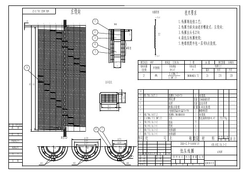
镀锌镀锡套1垫圈 10GB97.1-8516防松螺母 M10JB/ZQ4351-974拉带 L =2605B.137.3637.11M10×15螺栓GB5781-861接地片8B.516.3637.386垫脚垫块8B.193.16.1-13垫脚绝缘8B.786.16.1-11垫脚5B.022.16.1-166M1616斜垫圈防松螺母JB/ZQ4351-97GB/T853-882垫脚5B.022.16.1-21低压下夹件5B.071.16.1-31高压下夹件5B.071.16.1-332垫圈 16GB97.1-8525242116232220181917141213151110265B .640.16.1-2套Φ18×Φ22酚醛纸管Φ18×Φ22酚醛纸管4夹件绝缘5B.750.16.1-18绝缘管Φ18×Φ22×240888B.931.3637.2M16×365/50旁轭螺杆32JB/ZQ4351-97防松螺母 M16绝缘管Φ18×Φ22×830M16×1335/50拉螺杆8B.931.3637.21高压上夹件5B.071.16.1-15B.071.16.1-2低压上夹件123铁心材 料 数量名 称代 号序号重量单件总计15B.640.16.1-11备 注697845借(通)用件登记铁心装配5B.640.16.1-2描 图描 校底图总号旧底图总号签 字日 期8ZGS-Z.F-1600/35装配图代号标准化共 页日 期校 对工 艺批 准第 页重 量比 例设 计图 样 标 记审 定件/台更改标记签 字日期更改文件号处数序号 代 号名 称数量 材 料单 件总 重重 量备 注125B.640.16.1-1铁心装配135B.700.16.1-1器身绝缘146B.602.16.1-1高压线圈156B.602.16.1-2低压线圈165B.516.16.1高低压引线17GB5782-86螺栓M12*3548垫圈 1249JB/ZQ4351-86防松螺母M1241011125B.384.16.1-1油箱11314活门Φ25115变压器油116低压套管 2000A 417字牌各11819二位置负荷开关120吊拌42122箱盖123螺栓M16*553824螺母M16382740kg GB6170-86GB97.1-85GB12-885B.312.16.1数量 代 号5B.322.35.227序号25263129283033322塞子 M24*1.5插入式熔断器 40A 名 称分接开关13温度表真空压力表油位表11二位置负荷开关铭牌1备 注材 料WSP Ⅱ63/35-6*5重 量总 重单 件借(通)用件登记CAD 描 校CAD 描 图底图总号旧底图总号签 字借(通)用件登记CAD 描 校CAD 描 图底图总号旧底图总号签 字密封垫18B.161.16.1-2支架 L=23028B.472.35.3φ16耐油橡胶5B.300.16.1-1罩1接地螺栓2支架 L=23028B.161.16.1-1A ,B ,C 0,a ,b ,c ,35kV 630A 1高压套管3BJLW-35/10035343836XRNT-40.5/40-31.537信号温度控制器底板1无锡天一力50闸阀11B.710.16.1组合式变压器ZGS11-Z.F-1600/3535±2×2.5%/0.69kV Uk=6.5% Dyn11设 计审 定更改标记签 字日期更改文件号处数1B.710.16.1组合式变压器ZGS11-Z.F-1600/3535±2×2.5%/0.69kV Uk=6.5% Dyn11设 计审 定更改标记签 字日期更改文件号处数YZ-70UHZ-01BWS-705B.365.35.1信号温度计座1压力释放阀1YSF。
偏置直动滚子从动件盘形凸轮机构
河北工程大学机电学院机械原理课程设计说明书设计题目:偏置直动滚子从动杆盘型凸轮机构班级:姓名:学号:目录(一)设计题目及设计思路 (1)(二)凸轮基圆半径及滚子尺寸的确定 (1)(三)原始数据分析…………(四)从动杆的运动规律及凸轮轮廓线方程 (3)(五)凸轮机构的廓线设计原理 (4)(六)图解法设计盘型凸轮机构……………(七)检验压力角是否满足许用压力角的要求 (7)(八)机构示意简图 (8)(九)计算机源程序………(十)计算机程序结果及分析 (12)(一)机械原理课程设计的目的和任务一、机械原理课程设计的目的:1、机械原理课程设计是一个重要实践性教学环节。
其目的在于:进一步巩固和加深所学知识;2、培养学生运用理论知识独立分析问题、解决问题的能力;3、使学生在机械的运动学和动力分析方面初步建立一个完整的概念;4、进一步提高学生计算和制图能力,及运用电子计算机的运算能力。
二、机械原理课程设计的任务:1、偏置直动滚子从动杆盘型凸轮机构2、采用图解法设计:凸轮中心到摆杆中心A的距离为20mm,凸轮以逆时针方向等速回转,摆杆的运动规律如表:3、设计要求:①升程过程中,限制最大压力角αmax≤30º,确定凸轮基园半径r0②合理选择滚子半径rr③选择适当比例尺,用几何作图法绘制从动件位移曲线,并画于图纸上;④用反转法绘制凸轮理论廓线和实际廓线,并标注全部尺寸(用A2图纸)⑤将机构简图、原始数据、尺寸综合方法写入说明书4、用解析法设计该凸轮轮廓,原始数据条件不变,要写出数学模型,编制程序并打印出结果备注:凸轮轮廓曲率半径与曲率中心理论轮廓方程()()x xy yϕϕ=⎧⎨=⎩,其中2222////x dx d x d x dy dy d x d y dϕϕϕϕ⎧==⎪⎨==⎪⎩其曲率半径为:3 222 () x y xy xyρ+=--;曲率中心位于:2222()()y x yx xxy xyx x yy xxy xyρρ⎧+=-⎪-⎪⎨+⎪=-⎪-⎩三、课程设计采用方法:对于此次任务,要用图解法和解析法两种方法。
桥梁工程制图-识图

步骤2 用Stretch(拉伸)命令将上图中的各墩桩基按设计桩 长进行拉伸,完成桥梁立面主体。
步骤3 用Pline(多线段)命令绘制桥位处地面线及用Move (移动)命令将轴线编号移到墩台。完成后见图7-21。
2023/6/9
结 束 返回目录
返回第一张 上一张
下一张
第七章
第七章 桥梁工程图
第一节 大中桥桥型布置图 第二节 桥梁构件图 第三节 小桥及涵洞
2023/6/9
结 束 返回目录
返回第一张 上一张
下一张
第七章
第一节 大中桥桥型布置图
桥梁布置图(以图7-1为例)绘制时要对所 绘图形对象在大脑中形成一个比较清晰的认识, 对桥梁立面、平面、横断面进行总体布局。选 取合适的绘图比例(本桥用1:500)。然后再根 据各桥梁部件的详细尺寸要求进行组织及绘制。
2023/6/9
结 束 返回目录
返回第一张 上一张
下一张
第七章
桥梁立面主体图
2023/6/9
结 束 返回目录
返回第一张 上一张
下一张
第七章
四、桥梁平面图的绘制
在本桥的平面图中,桥梁以道路中心线成对称布置, 故可绘制半幅桥形,主题名称为“1/2平面”。在半幅桥 的图形中用左半部分来表示桥梁上部的布置,而右半部 分表示桥梁下部构造。图形构成主要是线条、矩形及圆。
叙述的内容如下: 1.尺寸标注 2.其他标注 3.文字及附注
图7-27
2023/6/9
桥墩 平面
图7-28
结 束 返回目录
返回第一张 上一张
下一张
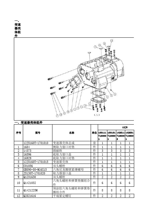
陕齿12JS160T图册
一、变速器壳体组件133111718000113313171800011425117180002142531710300112JS160T-1701010变速器壳体总成套111111684侧取力窗口衬垫件1111214373圆磁铁件3333316596底取力窗口盖件1111416929底取力窗口衬垫件1111512JS160T-1701015变速箱壳体件11116C01056双头螺栓件66667GB890-80-M16X15六角尼龙圈锁紧薄螺母件66668JS130T-1701020取力器窗口盖件11119Q1231630双头螺栓件222210Q1421032六角头螺栓和弹簧垫圈组合件件666611Q1421225M 预涂胶六角头螺栓和弹簧垫圈组件888812Q2821616平端紧定螺钉件222213Q341B16六角螺母件222214Q40112平垫圈件888815Q40116垫圈件666616Q40316弹簧垫圈件222217Q61304方槽锥形螺塞件1111序号12JS图号单位名称133111718000113313171800011425117180002142531710300112JS160T-1701025一轴总成套11116566二轴导套件1111219694一轴件12JS180-1701030-1一轴件111单位#N/A12JS序号图号名称#N/A1331117180001133131718000114251171800021425317103001A-3674离合器壳体总成套118677离合器分离轴套件2222215410SAE1号离合器壳件12JS180-1601015-5SAE1号离合器壳件111序号三、离合器壳体12JS#N/A单位名称图号133111718000113313171800011425117180002142531710300112JS160T-1707010后盖总成套11112JS200T-1707010后盖总成套1114347密封垫件1111216775副箱拨叉件1111310JS160-1707052加长中间轴盖件11114JS180-1707052副箱主轴齿轮压板件1111512JS160T-1707140同步器总成套1111612JS160T-1707047副箱加长中间轴焊接总成套111612JS200T-1707047副箱加长中间轴焊接总成套17副箱中间轴焊接总成套2222812JS160T-1707060副箱气缸总成套11812JS160T-1707060-1副箱气缸总成套1812JS200T-1707060副箱气缸总成套1912JS160T-1707105副箱主轴件111912JS200T-1707105副箱主轴件11012JS160T-1707106副箱主轴减速齿轮套1111012JS200T-1707106副箱主轴减速齿轮套11112JS160T-1707107副箱主轴垫圈件1111112JS200T-1707107副箱主轴垫圈件112192311E 短圆柱滚子轴承件111113A-C09008螺栓总成套444414A-C09009螺栓总成套111115Q171B1250六角头头部带孔螺栓和弹簧垫圈组合件件222216F96006凸缘螺母件111117GB305-82-120-1297止动环件222218JS180-1707051止动环件222219Q433120副箱中间轴盖件2222四、后盖组件12JS序号图号名称单位20JS180-1707053副箱中间轴盖衬垫件222221JS180-1707154主轴后轴承盖总成套111122JS180-1707156主轴后轴承盖衬垫件111123Q1421032M 圆锥滚子轴承件4423JS220-1707109圆锥滚子轴承件4424JS180-1707015后盖壳体件111125Q1421075预涂胶六角头螺栓和弹簧垫圈组合件件444426C09033六角头螺栓和弹簧垫圈组合件件11112712JS160T-1707108六角头头部带孔螺栓件1111133111718000113313171800011425117180002142531710300112JS160T-1707060-1副箱气缸总成套1114341范围档气缸活塞件1111214344O型密封圈件1111314345O型密封圈件1111414349气缸盖密封垫件1111514765O型密封圈件1111610G100BGB-T308钢球件1111712JS160T-1707062范围档气缸件1111#N/A五、副箱气缸组件12JS序号图号名称单位812JS160T-1707063螺塞件1111912JS160T-1707061范围档拨叉轴件111110F99857副箱换档气缸盖件111111GB890-80-M16X15六角尼龙圈锁紧薄螺母件111112J80-1702080定位弹簧件111113C09033六角头螺栓和弹簧垫圈组合件件111114Q617B18六角头螺塞件111115X11511褶皱铜垫圈件11111331117180001133131718000114251171800021425317103001JS180-1707154主轴后轴承盖总成套111117992里程表被动齿轮轴套件11112F91444油封件11113C01032主轴后轴承盖油封件11114JS180-1707155主轴后轴承盖件1111七、螺栓组件名称单位图号#N/A12JS序号1331117180001133131718000114251171800021425317103001A-C09009螺栓总成套1111117106铜垫圈件1111219709密封套件11113Q150B1075六角头螺栓件11111331117180001133131718000114251171800021425317103001A-C09008螺栓总成套1111#N/A名称单位12JS八、螺栓组件序号图号#N/A12JS序号图号名称单位117106铜垫圈件1111219709密封套件11113Q150B1032M预涂胶六角头螺栓件11111331117180001133131718000114251171800021425317103001A-C09018里程表接头小总成套11111F91005-1里程表接头件11112F91006衬套件1111#N/A九、里程表接头小组件#N/A序号图号名称单位12JS133111718000113313171800011425117180002142531710300112JS160T-1707050副箱中间轴焊接总成套11112JS200T-1707050副箱中间轴焊接总成套1112JS160T-1707051副箱中间轴件1111212JS160T-1707056副箱中间轴传动齿轮件1111133111718000113313171800011425117180002142531710300112JS160T-1707047副箱加长中间轴焊接总成套11112JS200T-1707047副箱加长中间轴焊接总成套1112JS160T-1707048副箱加长中间轴件1111212JS160T-1707056副箱中间轴传动齿轮件1111十一、副箱加长中间组件#N/A序号图号名称单位12JS十、副箱中间轴组件序号图号名称单位12JS1331117180001133131718000114251171800021425317103001A-C03002-11空气滤清调节器和螺塞总成套1111154015CA碗形塞片件11112A-4740-1空气滤清调节器总成套11113Q618B01六角头锥形螺塞件2222#N/A#N/A序号图号名称单位12JS1331117180001133131718000114251171800021425317103001F93060里程表接头总成套11A-C09018里程表接头小总成套11112F91444油封件1111133111718000113313171800011425117180002142531710300112JS160T-1701100二轴总成套11112JS200T-1701100二轴总成套1116763止动环件1111212JS160T-1701108滑套件1111312JS160T-1701121二轴六角键件5555412JS160T-1701122二轴齿轮花键垫件3333512JS160T-1701123二轴齿轮隔垫件1111612JS160T-1701125二轴倒档齿轮垫片件1111712JS160T-1701170一二档同步器总成套1111812JS160T-1701105二轴件111812JS200T-1701105二轴件1912JS160T-1701110二轴倒档齿轮件111912JS200T-1701110二轴倒档齿轮件1#N/A序号图号名称单位12JS序号图号名称单位12JS1012JS160T-1701111二轴一档齿轮件1111012JS200T-1701111二轴一档齿轮件11112JS160T-1701112二轴二档齿轮件1111112JS200T-1701112二轴二档齿轮件11212JS160T-1701113二轴三档齿轮件1111212JS200T-1701113件11312JS160T-1701114二轴四档齿轮件1111312JS200T-1701114二轴四档齿轮件11412JS160T-1701115二轴五档齿轮件1111412JS200T-1701115-1二轴五档齿轮件11412JS160T-1701115-1二轴五档齿轮件1512JS160T-1701116一轴齿轮件1111512JS200T-1701116-1一轴齿轮件11512JS160T-1701116-1一轴齿轮件16JS130T-1701180三四档同步器总成套111117Q5280310弹性圆柱销件1111133111718000113313171800011425117180002142531710300112JS160T-1701047中间轴总成套111#N/A序号12JS图号名称单位12JS200T-1701047中间轴总成套1119198中间轴止动环件1111212JS160T-1701057隔套件1111312JS160T-1701048中间轴件111312JS200T-1701048中间轴件1412JS160T-1701050中间轴三档齿轮件111412JS200T-1701050中间轴三档齿轮件1512JS160T-1701051中间轴四档齿轮件111512JS200T-1701051中间轴四档齿轮件1612JS160T-1701052中间轴五档齿轮件111612JS200T-1701052中间轴五档齿轮件1712JS160T-1701056中间轴传动齿轮件111712JS200T-1701056中间轴传动齿轮件1816JS200T-1701055中间轴四方键件11119Q5280514弹性圆柱销件111110X-6-E半圆键件11111331117180001133131718000114251171800021425317103001A-4729中间轴档板总成套1111119668中间轴轴承挡板件11112Q5280514弹性圆柱销件111112JS序号图号十七、档中间轴档板组件名称单位#N/A十六、中间轴档板组件133111718000113313171800011425117180002142531710300112JS160T-1701080倒档中间轴档板总成套111112JS160T-1701084杯形倒档垫圈件1111212JS160T-1701083倒档中间齿轮件111212JS200T-1701083倒档中间齿轮件13DS100-1701085滚针轴承件11114JS220-1701082倒档中间轴件11115Q2821212平端紧定螺钉件1111序号图号名称单位12JS#N/A#N/A13311171800011331317180001142511718000214253171030011.3.512JS160T-1707025二轴轴承总成套1111150118带止动槽的单列向心球轴承件1111212JS160T-1701124轴承支座件11113C01019止动环件1111#N/A十九、上盖组件序号图号名称单位12JS十八、二轴轴承组件133111718000113313171800011425117180002142531710300112JS160T-1702010-1上盖总成套112JS160T-1702010上盖总成套11112.7G100bGB-T308钢球件4444219.05G100bGB-T308钢球件333331634拨叉轴联锁销件222243220换档拨叉锁止螺钉件4444511066双头螺栓3-8″件4444612JS160T-1702015上盖件1111712JS160T-1702050倒档导块总成套1111812JS160T-1702054五六档导块件1111912JS160T-1702055倒档拨叉件11111012JS160T-1702056一二档拨叉件11111112JS160T-1702057三四档拨叉件11111212JS160T-1702058五六档拨叉件1111212JS160T-1702058-2五六档拨叉件11312JS160T-1702059五六档换档导块件1111312JS160T-1702059-1五六档换档导块件11412JS160T-1702063倒档拨叉轴件11111512JS160T-1702064一二三四档拨叉轴件2221512JS160T-1702064-1一二三四档拨叉轴件21612JS160T-1702066五六档拨叉轴件111117F96084压缩弹簧件111118F96085压缩弹簧件333319GB889-80-M12X125六角尼龙圈锁紧螺母件111120JS100A-1702072摆动拨头件111121JS100A-1702073支承轴销件111122Q351B10六角薄螺母件222223Q361B102型六角螺母件222224Q40112平垫圈件888825Q40310弹簧垫圈件222226Q5280630弹性圆柱销件222227X-1-603六角螺母件222212JS序号图号名称单位133111718000113313171800011425117180002142531710300112JS160T-1703010操作装置总成套1115276通气塞 件1111255534气管总成套1255534气管总成套1113F96194-6操纵装置壳体件13F96194-8操纵装置壳体件1114F99679-8横向换档杆件14F99679-17横向换档杆件111512JS160T-1703018-1拨头件1512JS160T-1703018拨头件111612JS160T-170302190°快换接头件1111712JS160T-1703022气路控制阀件11118DS100-1703024-1限位套件11119F96036-1压缩弹簧件11119F99983-1压缩弹簧件111110C03030圆柱销件111111C03052三通管接头件111112C09035弹性圆柱销件222213F91345横向换档杆衬套件222214F91353双H气阀衬垫件111115F91444油封件111116F96035LRC外换档臂件1116F96035-29LRC外换档臂件1117F99666侧板件111118F99669套件111119F99672端垫件111120F99673弹簧座件222221F99681低倒挡开关控制块件111122Q1420822六角头螺栓和弹簧垫圈组合件件444423Q151B1050六角头螺栓件1111序号图号名称单位12JS#N/A24Q218B0618内六角圆柱头螺钉件222225Q341B10六角螺母件111126Q40306弹簧垫圈件222227Q40310弹簧垫圈件666628Q43145轴用弹性挡圈件111129Q72224碗形塞片件11111331117180001133131718000114251171800021425317103001115276通气塞件11112、71284590°弯管接头件1111355511气管总成件1111455512气管总成件1111555521气管总成件1111612JS160T-170302190°快换接头件1111812JS160T-1703050单H阀总成套1111二十二、倒档倒导块组件二十一、单H阀组件#N/A二十一、单H阀组件序号图号名称单位12JS133111718000113313171800011425117180002142531710300112JS160T-1702050倒档倒导块总成套111118774-1倒档锁弹簧件11112510679倒档锁弹簧件128968倒档锁螺塞件1111312JS160T-1702051倒档导块件11114DS100-1702061倒档锁柱塞件1111#N/A序号图号名称单位12JS1425317106001142511710700111A 11B 33B 11B 11B 11A 66B 66B 11B 22B 66B 88B 22B 22B 88B 66B 22B 11B易损C常用B 非常用A 备注142531710600114251171070011A 11B A 11A易损C 常用B 非常用A 备注14253171060011425117107001A 22B A 11A备注易损C 常用B 非常用A1425317106001142511710700111A A 11B 11B 11B 11B 11B 11A A 22A 1B 1B B 11A A 11B B 11B B 11B 44B 11B 22B 11B 22B 22B 22B备注易损C常用B非常用A11B 11B 1B 41B 11B 44B 11B 11B142531710600114251171070011B 11B 11B 11B 11B 11B 11B 11B易损C常用B非常用A 备注11B 11B 11B 11B 11B 11B 11B1425317106001142511710700111B 11B 11B 511B 11B 易损C常用B非常用A 备注1425317106001142511710700111B 11B 11B 11B1425317106001142511710700114B备注易损C常用B非常用A易损C常用B非常用A备注11B 11B 11B142531710600114251171070011B 11B 11B备注易损C常用B非常用A1425317106001142511710700111A A 11A 11B 31425317106001142511710700111A A 11A 11B易损C常用B非常用A备注备注易损C常用B非常用A1425317106001142511710700111B 11B 11B 22B备注易损C常用B 非常用A14253171060011425117107001B 11B 11B1425317106001142511710700111A A 11B 11B 55B 33B 11B 11B 11B 11A A 11B3B 易损C常用B 非常用A 备注备注易损C常用B 非常用A11B 3B 11B 3B 11B 3B 11B 3B 1B 3B 1B 1B 3B 1B 11B 11B 1425317106001142511710700111A备注易损C常用B 非常用AA 11B11B 311A 2A 11B 3B 11B 3B 11B 3B 11B 3B 11B 211B 11B 1425317106001142511710700111B 11B 311B 易损C常用B 非常用A 备注142531710600114251171070011B 11B 11B 3B 11B 11A 311B 备注易损C常用B 非常用A1425317106001142511710700111B 11B 11B 311B 5备注易损C常用B 非常用A14253171060011425117107001A 1A 44B 33B 22B 44B 44B 11B 11B 11B 11B 11B 11B 1B 1B 1B 1B 11B 32B 42B 11B 311B 33B 11B 11B 11B 22B 22B 88B 22B 22B 22B 易损C常用B 非常用A 备注14253171060011425117107001A 11B B 11B B 11B 1B 11B 1B 11B 11B 11B 11B 11B 11B 11B 11B 22B 22B 11B 11B 1B 1B 11B 11B 11B 22B 11B 44B 11B 易损C常用B 非常用A 备注22B11B 22B 62B 11B 11B1425317106001142511710700111B 11B 11B 11B 11B 11B 11B易损C常用B 非常用A 备注1425317106001142511710700111B 1B 1B 11B 11B 11B 易损C常用B 非常用A 备注。
射频同轴电缆一览表

射频同轴电缆一览表看网络传输介质、同轴电缆知识专题,或进入讨论三、规格型号同轴电缆可分为两种基本类型,基带同轴电缆和宽带同轴电缆。
目前基带常用的电缆,其屏蔽线是用铜做成的网状的,特征阻抗为50(如RG-8、RG-58等);宽带同轴电缆常用的电缆的屏蔽层通常是用铝冲压成的,特征阻抗为75(如RG-59等)。
粗同轴电缆与细同轴电缆是指同轴电缆的直径大还是小。
粗缆适用于比较大型的局部网络,它的标准距离长、可靠性高。
由于安装时不需要切断电缆,因此可以根据需要灵活调整计算机的入网位置。
但粗缆网络必须安装收发器和收发器电缆,安装难度大,所以总体造价高。
相反,细缆安装则比较简单,造价低,但由于安装过程要切断电缆,两头须装上基本网络连接头(BNC),然后接在T型连接器两端,所以当接头多时容易产生接触不良的隐患,这是目前运行中的以太网所发生的最常见故障之一。
为了保持同轴电缆的正确电气特性,电缆屏蔽层必须接地。
同时两头要有终端器来削弱信号反射作用。
无论是粗缆还是细缆均为总线拓扑结构,即一根缆上接多部机器,这种拓扑适用于机器密集的环境。
但是当一触点发生故障时,故障会串联影响到整根缆上的所有机器,故障的诊断和修复都很麻烦,因此,将逐步被非屏蔽双绞线或光缆取代。
最常用的同轴电缆有下列几种:·RG-8或RG-1150Ω·RG-5850Ω·RG-5975Ω·RG-6293Ω计算机网络一般选用RG-8以太网粗缆和RG-58以太网细缆。
RG-59 用于电视系统。
RG-62 用于ARCn et网络和IBM3270网络。
公司专业从事射频信号电缆的技术研发、生产和销售,神宇通信秉承“矢志创造最优价值”理念,致力于打造国内、国际一流的特种电缆品牌。
配电箱及其字母说明
配电箱有型号,不同的厂家都有自己的型号。
国产型号有MLS、GCS、GCK GGD等,国外厂家有MD190,MNS,ArTu、Blokset、8PT等,一般标准的型号是GB7251.1。
区别:1、P-开启式低压开关柜,G-封闭式低压开关柜第二位:G-固定死,C-抽出式,H-固定、抽出混装式。
2、L(或D)-动力用,K-控制用,S-森源电气系统3、GGD较便宜,GCS、GCK为经济型。
4、GCK、GCS、MNS是低压抽出式开关柜。
5、GGD、GDH、PGL是低压固定式开关柜。
扩展资料配电箱尺寸的确定:1、当电箱只是照明电箱或者小动力时,进线小于10平方时,如果开关位数小于20位时,开关宽度尺寸加起来再每边加20MM就为电箱宽度,高度为开关高度加40MM,深度为开关最大深度加10MM。
2、当电箱只是照明电箱或者小动力时,进线小于10平方时,如果开关位数大于20位时,这时候电箱需要布置为两排开关,开关宽度尺寸加起来再每边加40MM就为电箱宽度,高度为开关高度加40MM,深度为开关最大深度加10MM。
3、当电箱只是照明电箱或者小动力时,进线小于10平方时,如果进线开关需要单独一排时,开关宽度尺寸加起来再每边加20MM就为电箱宽度,高度为开关高度加进线开关高度加40 MM,深度为开关最大深度加10MM。
4、当电箱为动力电箱时,或动力照明电箱时,算法基本与上面相同,不过当进线大于10平方时,要考虑进线的弯曲半径一级接线端子要预留足够的空间进线,当两排布置开关时,应考虑开关的布线走线.当然电箱尺寸没有定论的,要考虑实际的安装,要看实际接线图和考虑如何安排开关布置一级开关的走线。
5、如全是微型断路器根据位数(每位18毫米)确定,PZ系列配电箱有固定尺寸,回路超出80位可在图纸标识甲方确定(字样),设备控制箱标识设备自带,进线大于185mm2,输出大于2路尽量选用柜式等。
配电箱规格型号有哪些配电箱尺寸如何确定配电箱的型号规格配电柜型号有很多,一般不同的厂家都有自己的型号。
电视机BOM表ERP格式

转接板(T-CON)
PCS 1.0000
FFC软排线
PCS 4.0000
LED灯条
PCS 14.0000
反射片 扩散板 扩散片
PCS 1.0000 PCS 1.0000 PCS 1.0000
棱镜片
PCS 1.0000
棱镜片
PCS 1.0000
支撑柱
PCS 5.0000
锁复式支撑柱
(AR0120022与AR0120027同实物,整 合成AR0120027)65RWP606-材质:塑 胶 尺寸:20*27mm(符合RoHS标准) D65RWP619-黑色 材质:PET 尺 寸:708*85*0.05mm(长*宽*厚) 单 面上下背胶(配 V650DK1PS7/V650DK2-QS1/T650QVN02.0玻 璃三种结构共用)(供应商:瑞恒 辉)(符合RoHS标准) D65RWP619-黑色 材质:PET 尺 寸:708*85*0.05mm(长*宽*厚) 单 面上下背胶(配 V650DK1PS7/V650DK2-QS1/T650QVN02.0玻 璃三种结构共用)(供应商:瑞恒 辉)(符合RoHS标准) 18mm*30码 黑色(1码=0.9144米) 厚0.12mm(符合RoHS标准) 长=50米/卷 宽10mm 材质要求 9080A 白色(符合RoHS标准) D65RWP615-材质:PET绝缘 阻燃 94V0 尺寸:240*85*0.1mm(长*宽* 厚)背5000NS胶 配 LSC650HQ02/LSC650HQ03玻璃(符合 RoHS标准) 宽12mm*长30米 厚0.2mm 白色 耐高温80度 厚0.12mm(符合RoHS 标准) 大尺寸_CVT T.MS3458.U801超高 清主板(芯片型号:MSD3458HBE-LSW+MSB102KT(DVB-T/C/T2) 带音 效-B、图文丽音功能,带CEC、ARC 功能)使用8MByte(64Mbit)的FLASH 芯片 端口OPTICAL OUT,AUDIO IN、CVBS IN,YPBPR、(Mini)LINE OUT,HDMI*4(HDMI1/2/3/4做CEC 功能,HDMI1做ARC功能)RF IN、 USB P制(屏线插 座:CNW12/CNW1/51P)(符合RoHS标 准) 超高清-CVT PL.MS6M60.1(芯片型 号:MST6M60FV) V-BY-ONE 120HZ 转接板 12V供电 尺寸119*105mm 输出端口51P/CNW2 41P/CNW3, 输入端口51P/CNW4(符合RoHS标准)
160法兰成型机的总体设计(含全套说明书和CAD图纸)课件
学校代码:10410学号:20050428本科毕业设计题目:法兰成型机的总体设计学院:工学院姓名:李达林学号:20050428专业:机械设计制造及其自动化班级:机制052班指导教师:吴彦红老师二OO九年五月摘要本设计是关于法兰成型机(又名对称式三辊卷圆机)的总体设计,主要对卷圆机上下辊轮、压下装置以及卷圆机的总体进行设计和计算。
卷圆机结构型式为三辊对称式,在该结构中上辊下压提供压力,两下辊做旋转运动,为卷制板材提供扭矩。
该机是将各种型材卷制成法兰和圆环的一种高质量、高效益的卷圆装置,具有结构紧凑、操作简便、寿命长、噪声小、一机多用、质优价廉等优点,是工厂实现机械化生产的配套设备,该设备的上市可以大大减轻工人的劳动强度,提高企业生产效益。
关键词:法兰成型机;卷圆机;卷制;塑性变形Abstract: This design is about flange machine (three rollers symmetrical type roll round the overall design of machine), mainly to roll on the circle next roller, pressing device and roll machine design and calculation of the overall.Roll machine athreeroller symmetrical structure, in the upper roller press structure provides pressure, the two lower rollers make rotation, top provide torque. This machine is made of various profiles will roll ring flange and a high quality, high benefit rolls round device, with compact structure, easy operation, low noise, long service life, high quality and reasonable price multi-usage, etc, and is realized mechanization production factory, this equipment facilities listed can greatly reduce the labor intensity, improve production efficiency.Key words:Flange machine Roll round machine rolling Plastic deformation目录第一章绪论 ................................................................................................................................................. - 1 -1.1 设计任务 ........................................................................................................................................... - 1 - 1.2 国内外发展现状................................................................................................................................ - 1 -1.2.1 国外发展现状................................................................................................................................ - 1 -1.2.2 国内发展现状................................................................................................................................ - 2 - 1.3 本课程来源 ....................................................................................................................................... - 2 -第二章法兰成型机工作方案的选择............................................................................................................ - 3 -2.1 法兰成型方案的确定........................................................................................................................ - 3 - 2.2法兰卷制成型方式的选择................................................................................................................. - 3 -第三章传动方案及总体结构的设计............................................................................................................ - 5 -3.1 传动方案的设计................................................................................................................................ - 5 - 3.2 法兰成型机总体结构的设计............................................................................................................ - 5 -第四章力学分析与主参数的确定................................................................................................................ - 6 -4.1 卷圆的工艺过程分析........................................................................................................................ - 6 - 4.2 卷圆过程中的力学分析.................................................................................................................... - 6 - 4.3 工作辊轮的设计................................................................................................................................ - 6 -4.3.1三辊轮受力情况分析..................................................................................................................... - 6 -4.3.2 法兰成型机的主参数的确定........................................................................................................ - 7 -第五章压下装置的设计................................................................................................................................ - 8 -5.1 卷圆成型直径与标尺刻度的关系.................................................................................................... - 8 - 5.2 压下装置的设计................................................................................................................................ - 9 - 5.3 上辊轮轴的设计.............................................................................................................................. - 10 -5.3.1 轴的材料及结构的确定.............................................................................................................. - 10 -5.3.2 轴的受力分析.............................................................................................................................. - 11 -5.3.3 校核轴的强度.............................................................................................................................. - 12 - 5.4 螺旋传动设计 ................................................................................................................................. - 12 -第六章其它各主要零部件的设计及选用.................................................................................................. - 14 -6.1 箱体的设计 ..................................................................................................................................... - 14 - 6.2 “五大轮”的设计.......................................................................................................................... - 15 - 6.3 各主要部件的选用.......................................................................................................................... - 15 -第七章法兰成型机的主要技术参数.......................................................................................................... - 16 - 第八章设备的使用及其保养...................................................................................................................... - 17 -8.1 设备使用注意事项.......................................................................................................................... - 17 - 8.2 设备的润滑和保养.......................................................................................................................... - 17 -总结 ............................................................................................................................................................... - 18 -参考文献 ....................................................................................................................................................... - 18 -致谢 ............................................................................................................................................................... - 19 -第一章绪论1.1 设计任务卷圆是利用机械的方法使材料内部所承受的应力全部达到屈服极限,并将其卷制成所需半径的管筒件的一种冷加工方法。
派士数控转台技术文件AWUP160技术协议中英文-吴
派士数控转台技术文件AWUP160技术协议中英文-吴The Technical Agreement技术协议1. NC Rotary Table, type: AWUP160 , with Counterbearing: GGP160数控回转工作台, 型号:AWUP160; 及,尾座,型号:GGP160转台加尾座统一命名为: WWUP1601. 1Technical Description 技术描述1.1 .1 Execution of table platen台面Table platen manufactured from Meehanite GGG cast-iron, which is hydraulic tight and also gives highest rigidity- Ground clamping surface, precisely machined工作台台面采用德国米汉纳GGG高等级铸铁,具有非常高的刚性。
夹紧面采用精密的机械加工完成。
1.1.2 Base 底座The base casting is manufactured from Meehanite GGG cast-iron, which is hydraulic tight and also gives highest rigidity and stiffness.- supporting surface precisely machined- equipped with clamping slots/fixing holes- body bottom prepared to be installed the client's machine ———————————————————————————————————————————————工作台底座采用德国GGG高等级铸铁,具有非常高的刚性,采用独特的液压夹紧技术具有夹紧速度快,扭矩大,制动性强,平稳性高,抗倾覆力矩强的特点。
轻型屋面三角形钢屋架米跨度完整版
轻型屋⾯三⾓形钢屋架⽶跨度完整版轻型屋⾯三⾓形钢屋架⽶跨度HEN system office room 【HEN16H-HENS2AHENS8Q8-HENH1688】钢结构课程设计(说明书)题⽬ 12m轻型屋⾯三⾓形钢屋架设计指导教师付建科学⽣杨朗学号专业材料成型及控制⼯程班级完成⽇期 2014 年 6 ⽉ 19 ⽇轻型屋⾯三⾓形钢屋架设计说明书学指导教师:付建科? (三峡⼤学?机械与材料学院)1 设计资料与材料选择设计⼀位于杭州市近郊的单跨屋架结构(封闭式),要求结构合理,制作⽅便,安全经济。
原始资料与参数如下:①、单跨屋架总长36m,跨度12m ,柱距S=4m ;②、屋⾯坡度i=1∶3,恒载mm 2,活(雪)载mm 2;③、屋架⽀承在钢筋混凝⼟柱顶,混凝⼟标号C20,柱顶标⾼6m ;④、屋⾯材料:波形⽯棉⽡(1820×725×8);⑤、钢材标号:,其设计强度为215N ⁄mm 2 ⑥、焊条型号:E43型;⑦、荷载计算按全跨永久荷载+全跨可变荷载(不包括风荷载),荷载分项系数取:γG =,γQ =。
2 屋架形式及⼏何尺⼨对于于屋⾯坡度较⼤(i ≤1/8)的屋盖结构多⽤三⾓形钢屋架,⽽且三⾓形芬克式轻型钢屋架⼀般均为平⾯桁架式,其构造简单,受⼒明确,腹杆长杆受拉,短杆受压,受⼒较⼩,且制作⽅便,易于划分运送单元,适⽤于坡度较⼤的构件⾃防⽔屋盖。
本课题采⽤⼋节间的三⾓形芬克式轻钢屋架。
已知屋⾯坡度i=1∶3,即,屋⾯倾⾓: 43.18)/31arctan(==α屋架计算跨度:L 0=L-300=12000-300=11700mm屋架跨中⾼度:mm i L h 1950321170020=?=?=上弦长度: mm L l 89.61579487.0211700cos 200=?==α上弦节间长度:mm ll 47.153940==上弦节间⽔平投影长度:mm l a 5.14629487.047.1539cos =?=?=α根据已知⼏何关系,求得屋架各杆件的⼏何长度如图1所⽰(因对称,仅画出半榀屋架)。
大隈操作编程

大隈操作编程 Revised by Petrel at 2021O K U M A M C R-B I I简介设备描述:MCR-BII机型是大隈的高档次高刚性龙门式五面体加工中心,能够满足不锈钢、铸铁、铸钢等材料的铸锻件毛坯件的粗、精加工,凹模、凸模型面的铣削加工,同时保证具有较高的可靠性、稳定性、精度保持性和灵敏性。
最适合于大型模具、复杂形状工件的强力切削直至高精度加工的全过程加工。
本机型的运动形式由X轴(工作台前后移动)、Y轴(主轴箱左右移动)、Z轴(方滑枕上下移动)、W轴(横梁上下移动)、A轴(回转工作台)构成,XYZ为3坐标的直线运动轴,W轴同步控制,视工件高低进行横梁位置高低调节;X、Y、Z、A四轴构成四轴联动,自动换刀装置(ATC)和自动换头装置(AAC)位于立柱左侧面,可根据数控指令进行自动、手动和MDI方式进行换头和换刀操作,根据附加头配置的情况,对工件顶面及侧面共5个面,进行铣、镗、钻、扩、铰、攻丝等工序的完全自动循环的加工。
MCR-BⅡ35×80WA为动梁式龙门五面体加工中心,横梁上下行程1300mm,根据工件及夹具高低,相应定位横梁上下高度并自动夹紧;主轴转速范围10~4,000rpm,本台机床相应配备了立式附加头二个,最高转速4,000rpm。
每5度分度的90度附加头一个,最高转速3,000rpm,每5度分度的特殊90度扁细附加头一个,最高转速750rpm。
可实现高效率、宽广域的复合加工,并且配置了大隈第6代网络数字化数控系统OSP-P200M,特别适合于工程机械零部件的粗加工、半精加工和精加工。
控制系统OSP-P200M:OSP系统是百年机床制造厂商大隈公司40余年来自行开发的机电融合技术的结晶。
在数控技术、伺服技术、主轴技术、系统技术等方面均具有许多卓越的功能与性能。
OSP-P200M是大隈公司最新开发的面向2l世纪的第六代数控系统,基于WIN-XP平台开发的新一代数控系统,15英寸液晶触摸式显示屏,直观性很强的OSP浏览器。
派士数控转台技术文件AWUP160技术协议中英文-吴

The Technical Agreement技术协议1. NC Rotary Table, type: AWUP160 , with Counterbearing: GGP160数控回转工作台, 型号:AWUP160; 及,尾座,型号:GGP160转台加尾座统一命名为: WWUP1601. 1Technical Description 技术描述1.1 .1 Execution of table platen台面Table platen manufactured from Meehanite GGG cast-iron, which is hydraulic tightand also gives highest rigidity- Ground clamping surface, precisely machined工作台台面采用德国米汉纳GGG高等级铸铁,具有非常高的刚性。
夹紧面采用精密的机械加工完成。
1.1.2 Base 底座The base casting is manufactured from Meehanite GGG cast-iron, which ishydraulic tight and also gives highest rigidity and stiffness.- supporting surface precisely machined- equipped with clamping slots/fixing holes- body bottom prepared to be installed the client's machine工作台底座采用德国GGG高等级铸铁,具有非常高的刚性,采用独特的液压夹紧技术具有夹紧速度快,扭矩大,制动性强,平稳性高,抗倾覆力矩强的特点。
支撑面采用了精密机械加工完成。
配置有夹紧槽或安装孔。
工作台底座通过螺丝螺母安装在客户机床上1.1.3 Drive 驱动The table will be driven by servo motor of client'sWe are using worm and wheel sets from company Ott which have thehighest accuracy that is available in the market. It also has a patent pended zerobacklash adjusting system, where you can set backlash to zero with anydisassembly of the worm工作台驱动的伺服电机由客户自己提供。
解读电气系统图

CH1-63/2P C40A是:1、CH1为塑壳空气断路器的型号2、63是指该断路器触点的额定电流值3、2P为两极4、C40A为保护整定电流数值为40A②C65N—C40A/2Np1c65n施耐德旗下梅兰日兰牌断路器。
C曲线,40A电流的。
③ZR—YJV—3X16—CT/KBG32—SCEZR:阻燃,代表阻燃电缆(还应该标注阻燃级别A、B、C。
未标注可视为B级)YJV:交联聚氯乙烯绝缘铜芯电缆3X16:三芯电缆,每芯电缆截面16平方毫米CT:沿桥架敷设(还应标注桥架尺寸,可查阅平面图中桥架规格尺寸)KBG32:沿KBG管敷设,管规格32。
KBG:一种薄壁钢管SCE:吊顶内敷设。
④C65N/1P/C 16A ZR-BV-2×2.5 KBG16 1.0KWC65N是一种品牌断路器,C65是系列编号,N是指分断能力:6000A,C16中的C是指脱扣曲线类型,C型属配电保护类型,16是额定电流16A,1P是单级。
阻燃(zr)塑料绝缘铜芯线(bv)2根2.5mm2 穿16mm的电线管(kbg)扣压型负载功率是1kw⑤CM1-125/C80/3PCM1是常熟开关厂的塑壳开关是国内较好开关品牌塑壳框架电流为125A 额定电流为80A2P是微断3P是C是代表着开关的脱扣等级是C级,起到保护作用⑥3×[YJV22-1K-(4×95)SC100] 2×[YJV22-1K-(4×120)SC100]YJV22表示交联聚氯乙烯绝缘聚氯乙烯护套22表示铠装电缆,1K耐压1kV,4X95表示电缆4芯95平方,SC100表示穿100的镀锌钢管,前面的3表示3根同样的电缆,同样也是3根钢管。
2×[YJV22-1K-(4×120)SC100]类推。
不过,4X95的电缆的管径没有富余量,4X120的穿100的管太小至少应在125的。
4X120穿管有2个弯可能不行的7、YJV22(3*150+1*95)SC100YJV22交联聚乙烯绝缘电力电缆(具有卓越的热机械性能,优异的电气性能和耐化学腐蚀性能,还具有结构简单、重量轻、敷设不受落差限制等优点,是目前广泛用于城市电网、矿山和工厂的新颖电缆。
船英文缩写-36PP
NO 英语缩写中国语1 Abbreviation 缩写2 Aboard 在船上3 About ABT 约,大概4 Above Base Line A/B 在基线上5 Access Hole ACC.HOLE (人)通道口6 Access Ladder 出入用梯子7 Accessibility 可接近性8 Accessory 附属品,零件9 Accommodation Accom. 居住区10 Accommodation ladder 居住区楼梯11 Accommodation Space 居住区域12 Accumulator 蓄电池13 Acetylene Gas 乙炔气14 Acid Pickling 酸洗15 Adapter 适配器16 Additional ADD. 额外工作17 Additive 添加剂18 Adhesion Test 附着力试验19 Adjusting Piece Adj. Pc 调整用垫片20 After Peak Bulkhead A.P Bhd 尾尖舱壁21 After Peak Tank 尾尖舱22 After Perpendicular A.P 艉垂线23 Afterbody 后部船体24 Afterward AFT 向船尾方向25 Agitation 搅拌26 Air Compressor 空气压缩机27 Air Conditioning Plant 空气调节装置28 Air Ejector 空气排出器29 Air Fuel Ratio 气燃比30 Air Hole A/H 气孔31 Air Horn 气笛32 Air Pipe 空气管33 Air Test 气密实验34 Air Vent head 透气头35 Alignment 中心对齐,校准36 Allocated Stock Item ASI 分配貯藏资材37 Alternating Current AC 交流电38 Aluminizing 镀铝39 Aluminum Anode 防腐蚀铝40 Ambient Temperature 大气温度41 American National Standards Institute ANSI 美国标准协会42 American Society of Testing materials ASTM 美国材料实验协会43 Anchor 锚44 Anchor Bolt 锚栓,基础螺栓45 Anchor Chain 锚链46 Anchor Pattern 基础模式47 Anchor Pocket 锚穴48 Anchor Point 定位点49 Anchor Recess 锚穴50 Angle Valve Ang. V/V 角阀(L型)51 Anode Current 阳极电流52 Antenna 天线53 Anticorrosive Paint 防蚀漆54 Anti-Corrosive Tape 防腐蚀胶带55 Anti-Corrosive Treatment 防蚀处理56 Antifouling Paint 防污漆57 Anti-Skid Bar 防滑棒58 Appendix 附录(单数)59 Approval 认可60 Arc Strike 弧光放电61 Arc Time 发弧时间62 Arrangement ARR'T 布置,排列63 Asbestos 石棉64 As-Built Drawing 最终竣工图纸65 Assembly ASS'Y 装配66 Assembly Line 装配线67 Assembly Stage 装配工程68 Automatic Welding 自动焊接69 "Average Freight Rate Assessmentat the max of Deadweight COT" AFRAMAX AFRAMAX(8万吨位级原油运载船)70 Back Bead 背面焊接71 Back Gouging 后部表面气刨72 Backing Strip 衬垫73 Backside Undercut 背面咬边74 Balance Weight 配重75 Ballast 安定76 Ballast Control Room BCR 压载控制室77 Ballast Tank 压载舱78 Barrel 桶(158.99升)79 Base Line B.L 基线80 Base metal 母材81 Basic Desigh 基础设计82 Bead 焊珠83 Beam 横梁84 Bedplate 主机座85 Bellmouth 吸入口86 Bellows 风箱87 Bench mark 水准基点88 Bevel 斜角, 坡口89 Bevel Angle 坡口角度90 Bilge hat 舱底污水盖91 Bilge Holding Tank 舱底污水储藏罐92 Bilge Keel BLG.KEEL 舱底龙骨(防摇动)93 Bilge Plate 舭列板94 Bilge Radius 船底弯曲部的半径95 Bilge Well B/W 污水井96 Bill of Material BOM 材料明细表97 Bite Union 辊缝连接接头98 Bitumastic (Bituminous Cement) 沥青99 Blank Plate 板坯,基板100 Bleached Tar 漂白涂料101 Blind Plate 盲板102 Blister 水泡(油漆缺陷)103 Block BLK(B) 分段104 Block Assembly 分段装配105 Block Division BLK DIV. 分段划分106 Block Inspection 分段装配检查107 Blow Hole 焊接气孔108 Bollard 系船柱109 Boottop 水线漆110 Bosun(Boatswain) Store 甲板长仓库111 Both-sides Welding 双面焊112 Bottleneck 瓶颈113 Bottom BTM 船底114 Bottom Block 船底分段115 Bottom Plug 船底旋塞116 Bottom Shell Plating 船底外板117 Bottom Survery 船底检查118 Bow and Stern Construction 船首尾构造119 Bow Construction 船首构造120 Bow Door 船首门121 Bow Thruster 船头推进器122 Bowl 槽,斗,碗123 Bracket BKT OR B 加强筋板,轴板124 Brain Storming 集体研讨,想办法125 Brake Lining 闸衬,刹车面126 Brass 黄铜127 Brazing 铜焊,釬焊,硬焊128 Brazing Socket (釬)铜焊孔129 Breaking Strength 折断强度130 Breakwater 挡浪板131 Breast Hook 船首补强肘板132 Breathing Apparatus 呼吸器133 Bronze Casting 青铜铸件134 Brush Coating 毛刷涂漆135 Brush/Brush Holder 毛刷/毛刷固定器136 Bubbling 起泡137 Building Specification 建造规格书138 Bulb Plate BP 球扁钢139 Bulbous Bow 球鼻艏140 Bulk Carrier B/C 散装船141 Bulkhead BHD 舱壁142 Bulkhead Block 舱壁分段143 Bulkhead Piece 穿舱件144 Bulkhead Plan 舱壁结构图145 Bulkhead Stiffener 扶墙材146 Bulkhead Stool 舱壁托架147 Bulwark 舷墙148 Butt Welding 对接焊149 Butterfly valve 蝶型阀150 Buttock Line B.L 船体纵剖线151 Bypass Valve 旁通阀152 Cabin 船舱153 Cable Clench 电缆结154 Cable Duct 电缆通道155 Cable Tie 电线结束结156 Cable Trunk C.T 主干电缆157 Cableway 索道158 Calibration 标定159 Call Sign 呼号160 Camber 梁拱161 Canvas Cover 帆布蓬布162 Capacity Plan 容载度163 Capesize B/C 蓬角B/C164 Capstan 起锚机165 Car Carrier 汽车运输船166 Carbon Air Arc Gouging 一氧化碳气电弧气刨167 Cargo Control Room CCR 卸货控制室168 Cargo Handling System 货物处理系统169 Cargo Oil Pump 货油泵170 Cargo Segregation 货物隔离171 Cargo Space 货物区域172 Carling CARL'G (船的)短纵梁173 Carpenter's Workshop 木工车间174 Cast Iron 铸铁175 Cast Steel 铸钢176 Casting CAST'G 铸造,铸件177 Cathodic Protection 阴极保护178 Catwalk 天桥179 Cause of Defect 缺陷原因180 Caution plate 警告板181 Cavitation 气穴现象182 Center Flange Cent. Flg 中心法兰183 Center Girder 中心梁184 Center Keelson 中心线内龙骨185 Center Line C.L 中心线186 Center of Gravity C.G 重心187 Centrifugal Pump 离心泵188 Ceramic Backing 陶衬189 Certificate Cert. 检查合格证190 Chain Block 手拉葫芦191 Chain Locker C/L, CHAIN LKR 锚链锁192 Chain Pipe 锚链通过的管道193 Chain Stopper 止链器194 Chalk Test 划粉实验195 Chamfer C 倒角196 Chamfering Tool 倒角工具197 Channel CH, H(CH) 槽型钢198 Chart Room 图纸室199 Check Point 检测点200 Check Valve 止回阀201 Checked Plate CHK.PL. 花钢板202 Chemical Cleaning 化学洗涤203 Chemical Tanker 化学制品搬运船204 Chipping Hammer 破石锤205 Christening(naming) Ceremony 命名仪式206 Chronometer 记时计207 Clamp 夹钳208 Class 1 Pipe 一级管209 Class A Fires A级火灾210 Class A-60 Bulkhead A A-60 구역격벽A-60 区域舱壁211 Class Notation 船级代号212 Classification Certificate 船级证书213 Classification Rule 船级规定214 Classification Society 船级协会215 Clear Height 净高216 Clearance 间隙,空隙217 Cleat 夹板218 Client Request Item CRI 船主要求事项219 Clinometer 倾斜仪220 Closed Circuit Television CCTV 闭路电视221 Coaming COAM'G 舱口板222 Cold Galvanizing 冷电镀223 Collar Plate C.PL 加强板/复板224 Collier/Coal Carrier 运煤船225 Companionway 升降口226 Compartment 隔舱227 Compatibility 兼容性228 Component Assembly COMP.ASS'Y 小组装件229 Compressed Air 压缩空气230 Compulsary Item 必要项目231 Condensate Pump 冷凝泵232 Condenser 冷凝器233 Conning Station 操舵(指挥)位置234 Construction CONST. 建造235 Construction Profile 建筑结构轮廓图236 Consumables 易耗品237 Container Ship 集装箱船238 Control Panel 控制板239 Cooling Fresh Water CFW 冷却淡水240 Coordination 业务调整,相互协调241 Corrective Action Request CAR 对纠正措施的要求242 Corridor 通道, 走廊243 Corrosion Control 防腐方法244 Corrosion Inhibitor 防腐蚀剂245 Corrosion Rate 腐蚀度246 Corrugated Bulkhead CORR.BHD 槽形舱壁247 Cost Insurance and Freight CIF "到岸价(包括货价,运费,保险费)"248 Counter-balance Valve 背压阀, 反平衡阀249 Coupling Bolt 连接器螺栓250 Cowl head Ventilator 帽型通风筒251 Crack 裂纹252 Criteria 基准253 Cross Section 橫截面254 Cross Tie 交叉带255 Crossover Way 交叉通道256 Crude Oil Tanker COT 原油船257 Crude Oil Washing COW 原油清洗258 Cruiser Ship 巡洋舰259 Curing 硬化干燥260 Cutting CUTT'G 切割261 Cutting Drawing 切割图纸262 Cutting Tip 气割嘴263 Cutting Torch 割矩264 D mid (Moulded Depth) 型深265 "D/B W.B.T(Double Bottom Water Ballast Tank)" 双底压载舱266 Daewoo Shipbuilding Quality DSQS 大宇造船舶建造质量标准267 Dangerous Goods 危险货物268 Davit 挂艇架269 Daytime 日间, 白天270 Deadweight Tonnage DWT (总)载重吨271 Decibel Db 分贝(噪音单位)272 Deck DK 甲板273 Deck Below 甲板下部274 Deck Block 甲板块275 Deck Composition 甲板敷料277 Deck Fittings 甲板装置278 Deck Girder 甲板梁279 Deck Longitudinal 甲板纵骨280 Deck Machinery 甲板设备281 Deck Openning 甲板开口处282 Deck Plan 甲板结构图283 Deck Plating 甲板284 Deck Store 物料间285 Deck Under 甲板下部286 Deck Water Seal 甲板水封287 Deckhouse 甲板室,上层建筑288 Deep Tank 深舱289 Defect 缺陷290 Definition 定义291 Deflection Plate 反射板292 Deformation 变形293 Degreasing 脱脂294 Dehumidifier 除湿器295 Delete 刪除, 取消296 Delivery Lead Time 交货需要时间297 Department of Trade DOT 贸易部298 Derrick Post 起重机柱299 De-rusting 去锈300 Design Load 设计载荷301 Design Load Water Line DLWL 设计满载吃水线302 Detail DET. 详细,节点303 Detail Design 详细设计304 Detailed Assembly procedure DAP 详细装配工艺305 Detector 探测器,检测机306 Deutsche Industrie Normen DIN 德国工业标准307 Deviation 偏差308 Dew Point D.P [气,雾]露点309 Diagonal Line 对角线310 Diameter DIA 直径311 Diaphragm DIAPH. 橫膈膜312 Diesel Generator D.G 柴油发电机313 Diesel Oil DO 柴油314 Disassemble 分解315 Distribution 分散316 Dock Trial 系泊试车317 Double Bevel 双斜面318 Double Bottom D/B, D.BTM 双层底319 Double Continuous Fillet Welding D.C.F.W 双面连续角焊320 Double Fillet Weld 两面填角焊321 Double Hull 双船体322 Double Skin Construction 双船体构造323 Doubling plate/Doubler D/PL. 甲板,双层板/复板324 Down-Hand welding 俯(平)焊325 Draft Gauge 压差式风压计326 Draft Marks 吃水标志327 Drain Hole D/H 排水孔328 Drain System 排水系统329 Drain Trap 放泄弯330 Dresser Coupling 带盘根套筒331 Driptray 接油(水)盘332 Dry Film Thickness DFT 干镀膜的厚度333 Drydocking 干船坞334 Duct Keel 箱子型龙骨335 Dummy 虚拟的336 Duration 为期337 Dust Collector 集尘器338 Each EA 每个,个数339 Earth Connection 接地340 Echo Sounder 回声探测仪341 Edge Welding 边缘焊接342 Effective Throat 有效喉道截面343 Efficiency 效率344 Electric Cable Pipe ECP 电缆管345 Electric Load Analysis 电器负荷分析346 Electric Resistance Welding ERW 电阻焊接347 Electro Gas Welding EGW 电气焊348 Electrode Holder 电焊钳349 Electro-Hydraulic System 电动液压系统350 Electrostatic Hazard 静电危险351 Elevation ELEV. 正面图352 Elevator 升降机,电梯353 Embarkation Light 乘船灯354 Emergency Door 太平门,紧急出口355 Emergency Escape Trunk 紧急逃生通道356 Emergency Exit 太平门,紧急出口357 Emergency Fire Pump 应急消防泵358 Emergency Power Supply 应急电源359 Enclosed Space 封闭区域360 Engine Control Console 机控台361 Engine Control Room ECR 机控室362 Engine Room Arr't E/Rm Arr't 轮机舱布置图363 Engine Room Bulkhead E/R BHD 轮机室舱壁364 Ensign Staff 船尾旗杆365 Equipment List 设备目录366 Equipment Number 设备数367 Erection EREC.(E) 合拢368 Erection Schedule 合拢计划369 Even Keel 平板龙骨370 Exhaust manifold 排气集管371 Exhaust Valve 排气阀372 Expanded metal 多孔(拉制)金属网373 Expansion EXPAN , EXP. 展开374 Expansion Joint 膨胀节375 Expansion Tank 膨胀柜376 Explosion-Proof Lamp 防爆灯377 Explosive Atmosphere 爆炸危险区域378 Exposed Deck 露天甲板379 Extension Loop 伸缩弯380 Extension Rod 伸缩尺,伸长杆381 Extra Work 额外工作382 Eye Plate 眼板383 Fabrication Fab. 制作,加工384 Fabrication Shop 加工车间385 Face Flat F/F 面板386 Fairing(up) 流线型/整形387 Fairlead 导缆孔388 Fairleader 导缆孔389 False Bottom FALSE BTM. 活(假)底390 Fashion Plate FASHION PL. (钢板)组成船首材板391 Fatigue Analysis 疲劳分析392 Fender 护舷393 Fiber Glass 玻璃纤维394 Fiber Reinforced Plastics FRP "玻璃纤维增强塑料,玻璃钢"395 Fillet Welding 角焊396 Fin Stabilizer 减摇鳍397 Final Drawing 最终图纸398 Finish Paint 最后喷漆399 Finite Element Mothod FEM 有限要素法400 Fire Control Station 消防站401 Fire Damper 防火风闸402 Fire Extinguisher 灭火器403 Fire hose Box 消防水龙管箱404 Firemain Line 消防用管路405 Fit and Weld 铆焊406 Fit-up 组装407 Fix Jig 固定夹具408 Fixture 固定设备409 Flame Screen 火焰掩蔽物410 Flat Bar F.B 扁钢411 Flatness 平面度,扁平度412 Flexible Hose 软管,挠性管413 Flexible mounting 软安装414 Float Valve 浮阀415 Floating Dock 浮船坞416 Flood Light 泛光灯,探照灯417 Flooding Test 浸水试验418 Floor 肋板419 Floor Plate 地板,肋板420 Flow Chart 流程图421 Flue Gas 烟气,废气422 Flushing 冲洗423 Flux 熔剂424 Flux Cored Arc Welding FCAW 熔芯弧焊(CO2焊接) 425 Foam Fire Extinguisher 泡沫灭火器426 Foam Monitor 泡沫喷射装置427 Foot Valve 底(背压)阀/脚踩阀428 Fore Construction 船头构造图429 Fore Perpendicular F.P 艏垂线430 Forebody 船前身431 Forecastle Deck F'CLE DK 艏楼甲板432 Foremast 前桅433 Forepeak Tank 船首尖舱434 Forged Steel 锻造钢435 Forklift Truck 叉车436 Forward FWD 向船头方向437 Foundation FDN 底落438 Frame FR. 骨架,肋骨439 Frame Space F.S 肋骨间距440 Free of Charge 免费441 Free On-Board FOB 离岸价格442 Freefall Lifeboat 自由下落式救生艇443 Fuel Oil Tank 燃油舱444 Full Penetration F.P 全焊透445 Funnel 烟道446 Funnel Mark 烟道标志447 Furniture 家具448 Galley 厨房449 Galvanizing GALV. 镀锌,电镀450 Gangway 舷梯451 Gantry Crane 龙门吊,龙门起重机452 Gas Cutting 气割453 Gas Detection System 气体探测系统454 Gas Metal Arc Welding GMAW 气体金属弧焊455 Gas Tungsten Arc Welding GTAW 气体钨弧焊456 Gasket 垫圈457 Gastight Bulkhead 气密舱壁458 Gate Valve 闸阀459 general Arrangement G/A 总布置图460 General Cargo Ship 一般货船461 General Outfitting 一般舾装462 General Stock Item GSI 一般库存资材463 Girder GIR. 梁,槽钢/珩材464 Glass Reinforced Plastics GRP 玻璃钢465 Glass Wool 玻璃丝466 "Global maritime Distressand Safety System" GMDSS 全球海上遇险安全系统467 Global Positioning System GPS 全球定位系统468 Globe Valve 截止阀469 Goliath Crane 重型龙门起重机470 Gooseneck Ventilator 鹅颈式通风筒471 Gouging 气刨,表面切割472 Grade 等级473 Grand Assembly 主要装配474 Grating 格柵,柵极475 Gravity Arc Welding 重力式弧焊476 Gravity Tank (Head Tank) 重力罐477 Grease Nipple 注油嘴478 Grid 格子479 Grinding GRIND'G.(G) 打磨480 Gross Tonnage GT 总吨数481 Guard Rail 保护栏杆482 Guide Piece 定位片483 Gunwale 船舷上缘484 Gutter Bar 围板,挡板485 Gutter Pipe 排水管486 Gyrocompass 陀螺罗经487 Half Round Bar H.R.B 半圆钢488 Hand Grip H/G, HA, Ha 把手489 Handrail 栏杆490 Handysize B/C 便利B/C (5万吨以下的B/C)491 Hatch 舱口492 Hatch Coaming 舱口拦板(边材)493 "Hatch Cover(Folding/Side Rolling/Pontoon)" "舱口盖(折叠/卷边/浮桥)"494 Hatch End Beam 舱口端梁495 Hawse pipe 锚链管496 H-Beam (H) “H” 钢497 Headroom 头上空间/吊钩净高498 Heat Resistant Paint 耐热漆499 Heat Treatment 热处理500 Heating Coil 加热盘管501 Heating Torch 切割器,焊炬502 Heating Ventilation and Air Conditioning HVAC 通风及空调503 Heavy Fuel Oil HFO 重燃油504 Hexagon Head Bolt 六角头螺栓505 Hexagon Wrench 六角扳手506 High Stress Zone 高应力部位507 High Temp. Cooling Water Syestem H.T.C.W System 高温冷却水系统508 High Tensile Steel 高张力钢509 hinge 铰链510 Hogging(ref: Sagging) 弯度,挠度511 Hold 货舱512 Hold Frame 舱内肋骨513 Holding-Down Bolt 压紧螺栓514 Holiday 油漆漏掉部分515 Hopper Tank 舱底污水储藏边仓516 Horizontal HORI. 水平517 Horizontal Girder 水平梁518 Horizontal Stiffener 水平防摇材519 Horizontal(Position) Welding 水平焊接520 Hull Block Construction Method HBCM 船体分段建造法521 Hull Block Painting 整块上漆522 Hull Construction 船体构造523 Hull Form Coefficient 船型系数524 Hull Fouling 船体污损525 Hull Opening 船体开口526 Hull Outfit 船体装备527 Hull Parts List 船体附件表528 Hull Piping 船体管道系统529 Hull Preservation 船体保存530 Hull Steel 船体钢材531 Hull Strength 船体强度532 Hull Weight 船体重量533 Humidity Control 湿度控制534 Hydrant Valve 消防栓535 Hydraulic Jack 液压千斤顶536 Hydraulic Lift(Cherrypicker) 液压起重机537 Hydraulic Oil 液压油538 Hydraulic Power Pack 液压动力装置539 Hydrostatic Test 水压实验540 Hygrometer 湿度计541 I- Beam (I) “I” 钢542 Ice Breaker 破冰船543 Identical 同样的544 Immersion Suit 救生服545 Immersion Time 图漆后注水可能时间546 Impact Load 冲击荷重547 Impact Wrench 套筒扳手548 Impeller 叶轮,转子549 Impressed Current Cathodic Protection ICCP 外加电源阴极保护550 Inboard 舷内的551 Incinerator 焚烧炉552 Indicating Lamp 指示灯553 Indicator 指示器,指示剂554 Inert Gas Generator IG 惰性气体发生器555 Inflammable Life Raft 膨胀式救生阀556 Injector 喷射器557 Inorganic Zinc Silicate 无机硅酸锌558 Insert Block 嵌入块559 Insert Plate INSERT PL. 嵌入板560 Inspection INSP. 检查561 Installation Drawing 安装图562 Installation Manual 安装手册563 Institute of Electrical and Electronic Engineers IEEE "电气与电子工程师协会"564 Instruction Manual 安装指导说明书565 Interlock 互锁,连锁566 Intermittent Chain Welding 间断链焊567 Intermittent Staggered Welding 间歇交错焊接568 Internal Diameter ID 内径569 International Association of Classification Socities IACS 国际船级联合会570 International Electrotechnical Commision IEC 国际电工委员会571 International Gas Code IGC 国际气体编码572 International Labor Organization ILO 国际劳工组织573 International Load Line Convention ILLC 国际满载吃水线条约574 International Maritime Organization IMO 国际海事机构575 "International MaritimeDangerous Goods Code" IMDG "国际海上危险物运送规定,IMDG编号"576 "International MaritimePilots' Association" IMPA 国际船社协会577 "International Regulations forPreventing Collisions at Sea" COLREG 为防止海上冲突而定的国际协定578 "International StandardizationOrganization" ISO 国际标准化组织579 Intersection of Welding 交叉焊接580 Intrinsic Safety Barrier IS 本质安全隔离板581 Invar 不胀钢582 Inventory 详细目录583 Inverted Angle I.A. 逆角钢584 Jack Bolt 定位螺栓585 Jack Staff 旗杆586 Japanese Industrial Standard JIS 日本工业标准587 Jib Crane 悬臂起重机588 Jigs 焊机589 Jigs and Fixure 焊机及固定器具590 Joint Length 接头长度591 Jumping Stopper 止跳塞592 Junction Box JB 接线盒593 Just In Time JIT 及时供给594 Keel 龙骨595 Keel Block 底座,龙骨墩596 Keel Laying K/L 龙骨铺设597 Keel Laying Block 最初的龙骨装配块598 Keel Line 龙骨线599 Keel Plate 龙骨板600 Key Plan 索引图,总图601 Kingpost 主梁602 knuckle 肘节,转向节603 Knuckle Line K.L 折弯线,两个不同平面的交叉线604 Knuckle Point K.P 折弯点,两个不同线的交叉点605 Korea Register of Shipping KR 韩国船级协会606 Korean Industrial Standard KS 韩国标准工业规格607 Lamination 叠层608 Lap Joint 搭接处609 Lap Welding 搭焊,叠式焊接610 Lapping 搭接,重叠611 Lashing Wire 捆索612 Launching L/C (船)下水613 Lavatory 卫生间614 Lead Time 研制周期615 Leak Test 泄漏试验/密性试验616 Leg Length 焊角长度617 Length Between Perpendiculars LBP 垂线间长618 Length Overail LOA 全长619 Lever Block 操纵杆部件620 Life Buoy 救生圈621 Lifeboat 救生艇622 Lifesaving Equipment 救生装备623 Lift 升降机,升力624 Lifting Beam LIFT'G BEAM 起重横梁625 Lifting Lug LIFT'G LUG (起重)吊(挂)耳626 Light Welding 轻焊接627 Lightening Hole L/H 减(轻)重(量)孔628 Limit Switch 限位开关629 Line Heating 带钢加热630 Lines 型线图631 Liquid Penetrant Test PT 渗液探伤试验632 Liquified Gas 液化气633 Liquified Natural Gas LNG 液化天然气634 Liquified Petroleum Gas LPG 液化石油气635 List 目录,目次636 Living Quarters 居住舱637 Living Sqace 生存空间/可居住面积638 Load Line Marks 载重线标志639 Load Water Line 载重水线640 Longitudinal LONG. 纵向641 Longitudinal Bulkhead LONG.BHD 纵舱壁642 Longitudinal Space L.S 纵向间隔643 Longitudinal Strength 纵向强度644 Looking LOOK'G 观察方向645 Looking After 向船尾方向看646 Looking Forward 向船头方向看647 Loss 损失648 Louver 天窗,通气缝649 Lub. Oil Storage Tank L.O Stor. Tk 润滑油貯存舱650 Lubricating Oil LO 润滑油651 Lubricating Oil Pipe L.O Pipe 润滑油管652 Lubricator 注油器653 Luffing Cylinder 上下摆动汽缸654 M/V(Motor Vessel) 内燃机船655 Machinery Space 机器处所656 Magnetic Particale Inspection MPI 磁粉探伤检验657 Main Control Console 主控制盘658 Main Deck MAIN DK 主甲板659 Main Dimensions 主尺度660 Main Plate 主板661 Maintenance and Supply 维护及供给662 Maintenance Hatch 维护用开口663 Maker Drawing 制造者提供的图纸664 Man hole M/H 人孔665 Man hole Cover M/H COVER 人孔盖666 Manifold 歧管,总导管667 Manufacture Drawing 制作图纸668 Margin Plate 内底边板669 Marking MK 标记670 "MARPOL(The Prevention ofMarine Pollution from Ships" MARPOL 海洋污染防止协约671 Masking Tape 遮蔽胶带(涂色时防止污损)672 Master Schedule 主要日程计划/设计任务书673 Material Deficiency Report 资材缺陷报告674 Material handling 资材处理675 Material List 资材清单676 Material Preparation 资材准备677 Material Procurement 资材购买678 Material Specification 资材规格说明书679 Material Stowage and Issuing Plan 资材储存/支出计划680 Maximum MAX. 最大681 Maximum Continuous Rating MCR 最大持续功率682 Metacentric Height GM 稳心高度683 Metal Inert Gas Arc Welding MIG 金属揷入气弧焊684 Midship 船中685 Midship Section 舯横剖面686 Midship Section Coefficient 中横剖面系数687 midships 船舯部688 Minimum MIN. 最少689 Mock-Up (1:1的)模型(和实物等大的模型)690 Model Test 模型实验691 Mooring Arr't 停泊装置692 Mooring Trial 系泊试验693 Mooring Winch 系留绞盘694 Moulded line ML. 型线695 Movable Ramp 移动用斜板696 Mushroom Ventilator 菌型通风机697 Muster List 集合表698 Nameplate 铭牌699 Nautical Instrument 航海器械700 Navigation Bridge Deck NAV.BRI.DK 驾驶甲板701 Navigation Equipment 导航设备702 NC Machine 数字控制机械703 Needle Valve 针阀704 Network 网络,计划工程表705 Nitril Butadiene Rubber NBR 腈基丁二烯橡胶706 Nominal Diameter N.D 公称直径707 Nominal Size 公称尺寸708 NON WATER TIGHT BULKHEAD N.W.T.BHD 非水密舱壁709 Nondestructive Test NDT 无损探伤710 Nonferrous Metal 非铁(有色)金属711 Non-Return Valve 止回阀712 Nonslip 防滑713 Non-Sparking Tool 防爆工具714 Normal Condition 常态715 Normal Duration 正常需要时间716 Normal Working Hours 正常工作时间717 Norweian maritime Directorate NMD 挪威海运局718 Number of Coats 涂装次数719 Numerical Control N/C 数字控制720 Official Sea Trial 官方试航721 Offsets 型值表722 Oil Coaming 防漏油舱口围板723 "Oil Companies'International Maritime Forum" OCMIF 石油公司国际海事论坛724 "Oil Discharge MonitoringEquipment" ODME 排油检测装置725 Oil Seal 油封726 Oiltight Bulkhead 油密舱壁727 Oily Water Separator 油水分离器728 On the Job Training 工作培训729 On-block Outfitting 分段舾装730 On-Board 船上,船内,甲板上731 On-Board Outfitting 船上舾装732 Onboard Test 船上实验733 ON-Board Test Procedure 船上实验指导书734 On-ceiling Outfitting 上部(天花板)舾装735 One-sided Welding 单面焊接736 On-floor Outfitting 地板舾装737 ONLY 仅738 On-unit Outfitting 单元舾装739 Open Grating 格子模样的柵栏740 Open Space (Blue Sky) Fitting 露天安装741 Opening OPEN'G 开口742 Operating manual 操作说明书743 Operation Process Chart 运转工程图表744 Optical Fiber Cable 光缆745 Optimum Design 最佳设计746 Ordinary Frame 普通肋骨747 Ore Carrier 矿石运搬船748 Ore-Bulk-Oil Carrier OBO 矿油兼用船749 Outboard 船外侧750 Outdoor piping 室外管道系统751 Outfit Planning 舾装作业计划752 Outfitting OUTFIT. 舾装作业753 Outfitting 舾装作业754 Outfitting Quay 舾装码头755 Outfitting Scheduling System 舾装日程计划体系756 Outfitting Zone 舾装区域757 Outreach 舷外跨距758 Outside Diameter OD 外径759 Overboard Discharge 舷侧排水孔760 Overflow Pipe 溢流管761 Overhaul 大检(拆)修762 Overhaul inspection 检查763 Overhead (Position) Welding 仰焊764 Overhead Travelling Crane 桥式起重机765 Overheating 过热766 Overlap 重叠767 Overtime 超时768 Overweight 超载,超重769 Owner Furnished Equipment OFE 船东提供装备770 Owner's Approval Comment 船东认可意见771 Owner's Inspector 船东检查员772 Oxidation 氧化773 Pad 垫片,焊接区774 PAD Plate PAD PL. 垫板775 Padlock 挂锁,扣锁776 Paint Dipping 浸渍涂色777 Pallet 板台,W/P资材778 Pallet Material List PML 集装资材目录779 Panamax B/C 7万吨B/C780 Panel Line 平面板线781 Part Assembly 部件装配782 Part Number P/N 零(部)件号783 Partial Penetration P.P 部分焊透784 Passageway 通道785 Passenger Ship 客船786 Pedestal 軸承座,軸架787 Peel Off 剝離788 Pending 未決,保留789 Penetration Piece 贯通件790 Perforated Flat Deck PERF.FLAT DK 开口甲板791 Perforated Plate 多孔板792 Perpendicular 垂线793 Pferd Starke PS 马力794 Pillar P 支柱795 Pilot Ladder 领航员梯796 Pinhole 针孔797 Pipe Hole P/H 配管孔798 Pipe Schedule Pipe Sch 配管计划799 Piping and Instrumentation Diagram P&ID 管道及设备安装图纸800 Piping Diagram 管系图表801 Pitching 纵摇802 Plan 平面图803 Plan Approval 图纸认可804 Plan View 平面图805 Plan-Do-Check-Act Approach PDCA 計划/實施/檢査/措施的循環方式806 Planning and Scheduling 计划调度807 Plate PL. 钢板808 Platform Deck PLATM.DK 平台甲板809 Plimsoll's Line 载重线810 Polyethylene Coating 聚乙烯覆盖811 Polyurethane 聚胺脂812 Poop Deck POOP DK 艉楼甲板813 Porosity 多孔性814 Port P 左舷815 Port of Registry 船籍港816 Port Side 左弦,左侧817 Portable Tank 便携式水箱818 Post-Panamax 超巴拿马819 Pounds per Square Inch PSI 压力单位820 Pour Point 流动点821 Power Brushing P/B 动力工具使用前处理822 Power Factor 功率系数823 Power Panel 功率仪表板824 Pre-Erection P.E 分段装配,分段建造825 Preheating 预热826 Preoutfitting 预舾装827 Preservation Design 防蚀设计828 Pressure Tank 压力舱829 Preventive Maintenance PM 预防维护830 Principal Dimension 主尺度831 Process Analysis 工程分析832 Process Chart 流程图833 Process Control 流程管理834 Process Flow 工艺流程图835 Process Planning 工程计划836 Procurement Information 购买信息837 Producion Engineering 生产技术838 Producion Planning 生产计划839 Production Control 生产管理840 Production Drawing 生产图纸841 Production Need Date PND 生产需要日842 Production Technology 生产技术843 Productive Time 生产时间844 Productivity Cntrol Group PCG 生産力管理單位845 "Program Evaluation andReview Technique" PERT 工程计划评定和管理技术,统筹规划法846 Programmable Logic Controller PLC 程序逻辑控制器847 Protection Zinc 镀锌保护848 Prototype 原型,样机,样品849 Provision Crane 食品吊850 Purchase Order PO 资材购买定单851 Purchase Order Request POR 定货单要求852 Purifier 清洗器,净化器853 P-V(Pressure-Vacuum) Valve 压力/真空阀854 Qualification Test "(质量)鉴定实验,合格实验"855 Quality and Inspection Standards for Ships painting QISSP 船体涂装质量及检查标准856 Quality Control Q.C 质量控制857 Quality Control and Inspection 质量管理及检查858 Quality Deficiency Report 质量缺陷报告书859 Quality Standard 质量标准860 Quantity Q'ty 数量861 Radar Mast 雷达桅杆862 Radiator 辐射板,散热器863 Radio Room 无线电室864 Radiographic Test RT 放射线探伤试验865 Radius R 半径866 Radius End R.E 半径末端867 Rail Gate 栏杆中间的门868 Raw Material 原材料869 Reach -rod 拉杆870 Receptacle 储槽,揷座871 Re-Coating Interval 再涂装(时间)间隔872 Reefer Vessel 冷藏船873 Reference Ref. 参考874 Reference Drawing 参考图纸875 Reference Plane 基准面876 Reference Point 基准点877 Regulation 规定878 Reinforcement 加强,补强879 Relative humidity 相对湿度880 Relief Valve 安全阀881 Remnant Control 剩余材料管理882 Remote Control 遥控883 Remote Indication 遥示器884 Remote Operated Valve 遥控阀885 Repair of Defect 缺陷修理886 Repair Welding 补焊887 Rescue Boat 救生艇888 Research and Development R&D 研究开发889 Resin Chock 环氧树脂垫片890 Review of Drawing 图纸审评891 Revision Rev. 改正,修订892 Revolutions per minute RPM 每分走刀转数893 Rework 重做894 Rigging 缆具,索具895 Rolling 横摇896 Roll-On/Roll-Off Ship RO/RO Ship 汽车运输船897 Root Gap 根部间隙,焊缝根部面积898 Root Valve 分支阀899 Rope Guard 防绳罩900 Rose Box 舱底水过滤箱901 Round Bar R.B 圆钢902 Rubber Coating 橡胶涂层903 Rudder Angle Indicator 舵角指示器904 Rudder Stock 舵杆905 Rudder Trunk R/T 舵杆筒906 Rust-proof Oil 防锈油907 Sacrificial Anode 防蚀阳极908 Safe Load 安全载荷909 Safe working load SWL 安全工作载荷910 Safety Cage,Safety Hoop 安全环911 Safety Device 安全装置912 Safety Goggles 保护眼镜913 Safety Guard 保护围栏914 Safety of Life at Sea Convention SOLAS 国际海上人命安全公约915 Safety Stock 安全储备916 Safety Valve 安全阀917 Sagging (Ref. Hogging) 中垂(中拱)918 Sagging and Running 着色的凹凸及流动919 Salinity 盐分920 Scaffold Erecting 安装脚手架921 Scaffold Plank 脚手架922 Scaffold Removal 脚手架拆卸923 Scaffolding Support 按脚手架时用的支架924 Scale 尺度,刻度,比例925 Scallop 排水孔926 Scantling Draft 结构吃水927 Scantlings 构件尺寸,尺寸928 Scheduling 日程计划929 Scheduling and Control 日程计划及管理930 Schematic Piping Diagram 管道安装系统图931 Scope 适用范围932 Scope of Work 作业范围933 Screw Down Non-Return Valve SDNR 螺旋型单向阀934 Screw Pump 螺杆泵935 Scupper Pipe 排水管936 Sea Chest S/C 海底阀箱937 Seal Weld 密封焊缝938 Seamless Pipe SMLS 无缝管939 Section SEC. 截面图940 Section Modulus 剖面模数941 Sediment Davit 沉淀池用吊柱942 See berufasgenossenshaft SBG 德国船舶安全事项检查机关943 Segregation 分离944 Self Closing Valve 自闭阀945 Self Polishing Copolymer SPC 自抛光涂料946 Semi-submersible Drilling Rig 半潜式钻探设备947 Separator 分离器948 Sequence of Welding 焊接顺序949 Sewage Treatment Plant 污水处理装置950 Shackle 锚链节.卸扣951 Shaft Withdrawal Plan 船尾轴回收方案952 Shearing Force 剪应力953 Sheer 舷弧954 Sheer Strake 舷侧列板955 Shell Expansion Plan 外板展开图956 Shell Plating 列板957 Shielded Metal Arc Welding SMAW 电弧焊958 Shim Plate 垫板959 Ship maneuverability 船舶操纵性960 Ship Repair yard 修船厂961 Ship type 船型962 Shipbuilders Council of America SCA 美国造船业协会963 Shipbuilding 造船964 Shipowner 船东965 Shipside Valve 船舷阀966 Shipyard 造船厂967 Shop Primer 保护低漆968 Shop Test 车间试验969 Shore Connection 通岸接头970 Short-Circuit Test 短路实验971 Shot Blasting 喷丸处理972 Shot(of Chain) 锚链节973 Shut-Down 紧急停机974 Side Girder 旁底桁975 Side Longitudinal 舷侧纵骨976 Side Openning 舷侧开口977 Side Ramp 舷侧跳板978 Side Scuttle/Porthodle /Portlight 舷窗979 Side Shell S.S, S.SHELL 舷侧列板980 Sight Glass 观察(窥视)孔981 Silencer 消音器982 Silver Brazing Coupling 银铜焊联轴器983 Simulation 模拟实验984 Single Point Mooring SPM 单点系泊系统985 Sistership (按同一设计图纸建造的)姊妹船986 Skeg 呆木,尾鳍987 Skid Plate 滑板988 Slag Inclusion 夹渣989 Slamming 拍动,砰击990 Sleeve Joint 套筒接头991 Slop Tank 废油舱992 Slope 倾斜993 Slot Hole 孔洞。
中辉某126mx56m工程设计全套CAD图
IGES文件格式

IGES文件格式IGES文件由五或六段组成:标志(FLAG)段;开始(START)段;全局(GLOBAL)段;元素索引(DIRECTORY ENTRY)段;参数数据(PARAMTER DATA)段;结束(TERMINATE)段。
其中,标志段仅出现在二进制或压缩的ASCII文件格式中。
一个IGES文件可以包含任意类型、任意数量的元素,每个元素在元素索引段和参数数据段各有一项,索引项提供了一个索引以及包含一些数据的描述性属性;参数数据项提供了特定元素的定义。
元素索引段中的每一项格式是固定的,参数数据段的每一项是与元素有关的,不同的元素其参数数据项的格式和长度也不同。
每个元素的索引项和参数数据项通过双向指针联系在一起。
文件每行80个字符。
每段若干行,每行的第1~72个字符为该段的内容;第73个字符为该段的段码;第74~80个字符为该段每行的序号。
段码是这样规定的:字符“B”或“C”表示标志段;“S”表示开始段;“G”表示全局段;“D”表示元素索引段;“P”表示参数数据段;“T”表示结束段。
1 开始段(Start Section)文件开始段可供人阅读的有关该文件的一些前言性质的说明。
在第1~72列上可以写入任何的内容的ASCII码字符。
一个开始段例子如下:图ASCII码的IGES开始段的格式2 全局段(Global Section)文件的全局段包含由前置处理器写入、后置处理器处理该文件所需的信息。
它描述了IGES文件在使用的参数分隔符、记录分隔符、文件名、IGES版本、直线颜色、单位、建立该文件的时间、作者等信息。
详细说明见下表:索引类型描述1字符串参数分隔符(缺省为逗号)2字符串记录分隔符(缺省为分号)表IGES全局段内容3 元素索引段(Direction Entry Section)每一种元素对应一个索引,每个索引记录含有20项,每一项占8个字符,每个索引在元素索引段中占两行,索引说明如图:图ASCII码的IGES元素索引段格式说明如下:(1)元素类型号;(2)参数指针,说明该元素的参数在参数数据段的开始行号;(3)版本,说明采用的IGES版本号;(4)线型,IGES文件中的线型用整数表示,所提供的线型如下:1:Solid(实线)2:Dashed(虚线)3:Phantom(剖面线)4:Center(中心线)其它线型,需在文件中自行定义;(5)图层,存放图层名或它的指针;(6)视图,存放视图指针;(7)变换矩阵,此项为块插入时相应的变换矩阵的索引在索引段的开始行号;(8)标号显示;(9)状态号,从左到右,每两个字符含义如下:第1,2个字符:存在的状态;第3,4个字符:相关性;第5,6个字符:形成特征;第7,8个字符:体系特征。
