瓦楞纸欧洲标准
国际纸箱规范标准-各纸箱箱型类别(纸箱必看)

国际纸箱箱型标准瓦楞纸箱的箱型结构.在国际上普遍采用由欧洲瓦楞纸箱工业协会(FEFCO)和瑞士纸板协会(ASSCO)联合制定的国际纸箱箱型标准。
以往对纸箱包装结构的语言描述既冗长又复杂,现在改用本标准后,箱型用简单的数字代号表示,使任何国家的人不论在语言或其他方面所存在的差异都容易理解。
纸箱包装的订单和规格都可参照本标准。
本标准只能由FEFC0和ASSC0作增补和修改。
本标准下的系统结构为纸箱内部视图纸箱规格尺寸除非另有规定,所有纸箱内径尺寸都以毫米为单位表示如下:长度(L)×宽度(B)×高度(H)其中,长度(L)=开口处最长的尺寸宽度(B)=开口处最短的尺寸高度(H)=从开口处至箱底水平面的尺寸长度、宽度和高度的规格尺寸在纸箱结构说明中都作了明确规定,在某些箱型中其宽度要大于长度。
测定纸箱尺寸,必须在规定的标准气候条件下进行,在平铺的纸板上从压线中心处开始.同时注意量具本身的厚度。
对于罩盖型纸箱,罩盖的高度(h)可在斜线后用第四尺寸表示,即355 X 205×120/40毫米(L) (B) (H) (h)对于搭口外部摇盖纸箱,搭口(o)区域的长度可在斜线后用第四尺寸表示,即355×205×1 20/40毫米(L) (B) (H) (o)纸板规格尺寸除非另有规定,所有瓦楞纸板尺寸都以毫米为单位表示如下:第一尺寸×第二尺寸其中,第一尺寸=沿胶缝的长度第二尺寸=垂直于胶缝的长度纸箱式样某些纸箱类型衍生自同种式样,因而无需就此类型另行规定。
但是在表示基本箱型式样的数字后面需添加一个后缀数字.并用破折号隔开,如0201—2。
具体到每个生产商,这样的式样标准可能会略有不同。
纸箱式样组合下图所示的纸箱结构式样为纸箱的基本类型。
若纸箱的结构为两种或三种基本类型的组合,如摇盖组合,也同样可以表示为:上摇盖0204,下摇盖0215 这样的式样还可以表示为O204/O215(上摇盖/下摇盖)。
欧洲废纸标准(CEPAC)

欧洲废纸标准(CEPAC),根据数字的代号系统对废纸的等级进行编号。
A 组普通品种:欧废A0---未经分捡的混合废纸。
欧废A1---混合未分选的纸和纸板,不含禁止物和废弃物。
各种级别的纸和纸板,无短纤维的限制。
欧废A2-混合分选过的纸和纸板,报纸和杂志含量不超过40%的各种纸和纸板的混合。
欧废A3-灰色纸板边角料,印刷过或未印刷过的,有和无白色衬里的灰色或混合纸板,无瓦楞材料。
欧废A4-超级市场瓦楞纸和纸板。
用过的包装纸和纸板,包括70%的瓦楞纸,其余的为厚纸板和包装纸。
欧废A5-废弃的瓦楞纸箱。
用过的各种质量的瓦楞纸箱。
欧废A6-新的瓦楞纸箱切边。
欧废A7-过量发行的手册和杂志。
欧废A8-混合的报纸和杂志I。
混合的报纸和杂志,包括至少50%的报纸,胶水可有可无。
欧废A9-混合的报纸和杂志II。
混合的报纸和杂志,至少包括60%的报纸,胶水可有可无。
欧废A10-混合的杂志和报纸。
混合的报纸和杂志,至少包括60%的杂志,胶水可有可无。
欧废A11-分选过的图片纸。
从住户中收集到的图片纸,报纸和杂志最少各占40%,不可脱墨的纸和纸板的比例最多为1.5%,具体比例可由卖双方协商而定。
B组-中级品种:欧废B1-阅读过报纸。
最多包含5%彩页或广告插页的报纸。
欧废B2-未售出的过量发行的报纸。
未售出的日报,不含附加的修饰材料、彩色插页。
未售出的报纸,限制曲线印刷图出现。
未售出的日报,没有额外的插页或作解释说明的彩页存在,线绳允许。
不允许曲线印刷图出现。
欧废B3-浅色印刷的白色切边。
浅色印刷的白色切边,主要为机械浆层的纸,无胶水。
欧废B4-深色印刷的白色切边。
深色印刷的白色切边,主要为机械浆层的纸。
欧废B5-书皮切边。
欧废B6-不含胶带的书皮切边。
分选过的办公用纸。
欧废B7-彩色信纸。
信纸、印刷或未印刷的,带颜色的印刷纸或书写纸,没有碳纸和硬皮。
欧废B8-白色胶印纸。
书籍,包括漏印的书籍,不含硬皮,主要为白色胶印纸,只有黑色印刷,含不超过10%的带涂层的纸。
瓦楞纸板厚度标准

瓦楞纸板厚度标准一、瓦楞纸板简介瓦楞纸板是一种由面纸、瓦楞纸和芯纸组成的纸制包装材料。
瓦楞纸板具有良好的缓冲性能、抗压强度和耐磨性,广泛应用于各种包装产品和物流运输领域。
根据我国瓦楞纸板行业的统计数据,近年来,我国瓦楞纸板产量持续增长,已成为全球最大的瓦楞纸板生产和消费国。
二、瓦楞纸板厚度标准概述1.瓦楞纸板厚度的定义瓦楞纸板的厚度是指在垂直于瓦楞方向的方向上,瓦楞纸板单位面积的厚度。
通常用毫米(mm)作为单位。
2.我国瓦楞纸板厚度标准我国关于瓦楞纸板厚度的标准为GB/T 6543-2008《瓦楞纸板》。
该标准规定了瓦楞纸板的分类、规格、尺寸、物理性能和试验方法等方面的内容。
根据该标准,瓦楞纸板的厚度分为以下几个等级:A、B、C、D、E、F。
3.国际瓦楞纸板厚度标准在国际上,关于瓦楞纸板厚度的标准主要有两个:一个是欧洲的EN 652《瓦楞纸板》标准,另一个是美国的ASTM D3792《瓦楞纸板厚度、密度和物理性能的测试方法》标准。
这些标准对瓦楞纸板的厚度、规格、物理性能和试验方法等方面进行了规定。
三、瓦楞纸板厚度检测方法1.测量仪器测量瓦楞纸板厚度的仪器主要有厚度计、千分尺、电子测厚仪等。
2.测量步骤(1)将瓦楞纸板放置在平整的测量台上,保持表面平整、无皱褶;(2)选取测量区域,一般为100平方毫米;(3)将测量仪器放置在瓦楞纸板上,使其与纸板表面紧密接触;(4)读取测量仪器显示的厚度值,记录并进行计算。
3.厚度测量注意事项(1)测量时避免瓦楞纸板表面受损或变形;(2)测量仪器应定期校准,保证测量准确性;(3)测量结果应取多次测量的平均值。
四、瓦楞纸板厚度标准在实际应用中的重要性1.影响产品质量瓦楞纸板的厚度直接关系到产品的缓冲性能、抗压强度等物理性能。
合适的厚度可以保证产品在运输过程中不易损坏,提高产品品质。
2.影响产品价格瓦楞纸板的厚度直接影响其成本。
厚度较大的瓦楞纸板生产成本较高,因此在购买时,厚度合适的瓦楞纸板可以降低产品价格。
国外瓦楞纸标准
国外瓦楞纸标准一、尺寸和规格瓦楞纸的尺寸和规格是按照不同国家和地区的标准来制定的。
一般来说,瓦楞纸的尺寸包括宽度、长度和厚度。
在欧洲,瓦楞纸的标准宽度为900mm,长度可根据需要进行定制,厚度一般为3-4mm。
在美国,标准宽度为1200mm,长度和厚度与欧洲相同。
另外,根据不同用途,瓦楞纸还可以分为单瓦楞纸板和双瓦楞纸板。
二、质量和重量瓦楞纸的质量和重量也是重要的指标。
一般来说,高质量的瓦楞纸应该具有一定的抗拉强度、抗压强度和弹性模量等物理性能。
同时,重量也是一个重要的参数,它决定了瓦楞纸的厚度和密度。
在欧洲和美国,对于不同类型的瓦楞纸都有明确的质量和重量要求。
三、外观和表面质量瓦楞纸的外观和表面质量也是非常重要的。
好的瓦楞纸表面应该平整、光滑、无裂纹、无气泡等缺陷。
此外,颜色、光泽度等外观指标也需要符合相关标准。
四、物理性能瓦楞纸的物理性能主要包括抗拉强度、抗压强度、抗弯强度、弹性模量等。
这些性能指标决定了瓦楞纸在使用过程中的耐久性和稳定性。
不同类型的瓦楞纸有不同的物理性能要求,需要根据具体用途进行选择。
五、化学性能瓦楞纸的化学性能主要包括pH值、化学物质含量等。
这些指标决定了瓦楞纸在使用过程中的安全性和环保性。
对于食品包装等特殊用途的瓦楞纸,需要特别关注化学性能指标。
六、卫生和环保要求瓦楞纸作为一种包装材料,需要符合相关的卫生和环保要求。
在生产过程中,需要使用环保材料,减少废弃物的产生。
同时,在使用过程中,也需要保证食品等物品的安全卫生。
在欧洲和美国等国家和地区,对于瓦楞纸的卫生和环保要求都有明确的规定和标准。
七、包装和标识瓦楞纸在运输和存储过程中需要进行包装和标识。
包装应该具有足够的保护功能,防止瓦楞纸受潮、损坏等。
标识应该清晰、简洁,包括产品名称、规格、生产日期等信息。
在欧洲和美国等国家和地区,对于瓦楞纸的包装和标识都有明确的规定和标准。
八、试验方法和检验规则为了确保瓦楞纸的质量和性能符合相关标准,需要采用正确的试验方法和检验规则进行检测。
欧洲瓦楞纸板生产现状

增为3 2 4 亿平方米 ,2 0 年为3 5 O2 9 亿平方米 2 0 03 年和 2 o 年分别增加到4 9 平方米3 4 1 04 0亿 1 2 亿平方 : 1
米 , 2 o 年 、2 0 2. 2 0 年分 别 增 至 4 8 平 05 0 6F 0 7 别增 到8 亿 平方 米和 8 0 7 0 8 6 8
一
国瓦楞纸板 为9 亿 平方米 .比上年增长 8 4 ,创 1 .% 历史最 高产 量 纪录 .占F C 瓦楞纸板 总 产量 的 F 0 E 2 .名 1 6 。意大利 瓦楞纸板产量在 欧洲仅 少于德国 , 1 9 ~ 0 1 的产量都为 5 多亿平方 米 ,2 0 年 9720年 O 02
个 行 业 组 织 ,欧 洲 绝 大 部 分 瓦 楞 纸 板 都 是 这 个 组
织 的 成 员 国生 产 的 ,这 个 组 织 就 是 F F 0 EC 。 F C ( 洲 瓦楞 纸 板 生 产 商 联 合 会 )是 欧 洲 F 0 欧 E
瓦楞 纸板 的行 业机 构 .拥有 2 个会 员 国 .其 中包 2 括 德 国 、意 大 利 、英 国 、法 国和 西班 牙等 欧洲 主 要瓦楞纸板生产 国。F C 的瓦楞纸板 产量 占欧洲 F 0 E 总产量 的很大 比例 .如 l 9 年为 9 %.1 9 年为 9 5 1 8 9
吨 .波兰为1 4 4 万吨 。 FEFC 0各 国 的 瓦 楞 纸 板 生 产 企 业 数 量 , 1 9 ~ 0 1 均在 5 0 以上 ,此后逐 渐减 少 , 8 2 0年 9 0 家
国一 共生产 了4 亿平方 米瓦楞纸板 .创历史最高 9 1 产 量纪 录 。但 2 8 0 年和 2 0 年 F C 瓦楞 纸板 0 0 9 F 0 E
欧洲纸箱标准
欧洲纸箱标准主要参考以下几个方面:
1. 欧洲标准EN 6543-1992《瓦楞纸箱》:这个标准规定了瓦楞纸箱的设计、尺寸、材料、生产工艺和质量要求。
2. 欧洲标准EN 6544-1992《瓦楞纸箱》:这个标准主要涉及瓦楞纸箱的尺寸、形状、结构和强度要求。
3. 欧洲标准EN 6545-1998《瓦楞纸板耐破强度测试方法》:这个标准规定了瓦楞纸板的耐破强度测试方法。
4. 欧洲标准EN 6546-1998《瓦楞纸板边压强度测定方法》:这个标准规定了瓦楞纸板边压强度的测定方法。
5. 欧洲标准EN 6547-1998《瓦楞纸板厚度测定方法》:这个标准规定了瓦楞纸板厚度的测定方法。
6. 欧洲标准EN 2679.7-1981《瓦楞纸板戳穿强度的测定法》:这个标准规定了瓦楞纸板戳穿强度的测定方法。
7. 欧洲ETAD 标准:ETAD 是欧洲包装与环境协会,其制定了针对包装材料的环境友好性、循环利用、生物降解等方面的系列标准。
8. 欧洲卡板标准:欧洲卡板标准主要涉及卡板的尺寸、材质、强度和耐久性等方面。
从瓦楞纸板托盘的欧洲标准说起

标 准 ,促 进推 广 了标 准尺 寸 的运 用 。 图 1是 瓦楞纸板 托 盘和可 回收塑 料托盘 在物流
中 的对 照 图 。从 中可 以看 出 ,瓦楞纸 板托 盘使 用 以
瓦楞纸 箱 由木 纤维构 成 ,木纤 维可 经 自然作 用 犀,大 多数 废弃 的瓦楞 纸 箱可 回收后 再造 成新 的 斗.所 以用瓦楞 纸板 包装取 代 木质包 装 ,可大 量
文 / 张 兰
在许 多经济 发达 的国 家中 .瓦楞纸 板托 盘 已广 泛运 用于许 多商品 ( 如水 果和蔬菜 )的包装 与运 输 。 瓦楞纸 板托 盘是现 在广泛 地被 欧洲 和其他 许 多 : 的水果 、蔬菜 行 业接受 和使 用 的包 装形 式 。与
l 质 的托盘 相 比 .用瓦楞纸 板做 托盘 能带 来 良 材
害 人体 。 ③瓦楞 纸板 属于绿 色包 装材 料 ,与 当前 倡导 的
】 经济效 益和 社会 效益 。建 立瓦楞 纸板 托盘 的统
i 有着重 要意 义 。 准
瓦楞纸板 是一 个 多层 的黏 合体 ,它最少 由一层
形芯纸夹层 ( 称 坑张 ”或 瓦楞 纸 俗 )及一
绿 色包 装相适 应 ,完全 可 以循 环使 用 ,对保 护 森林 资源 、维 护生 态平 衡有 显著 贡献 。 ④瓦楞纸 板 由于 自身结构 的特 点 ,具有 很好 的 保护 和防 震功 能 .瓦楞纸 板托 盘有 利 于保护 好商 品 并 减少 损失 ,适合 机械 化 搬运 ,速 度较 快 。 ⑤瓦 楞纸板 托盘 结构稳 定性 好 ,有很 强 的机械 强度 ,有突出的抗压能 力和抗弯能 力.不 易变形 ,通 过增 高堆 码 ,能有 效利 用贮 藏 空厂 再重 新加 工制造 成新 的 瓦 楞 纸 板 .而可 回收塑 料托 盘 回收 以后则 是经 由洗涤 中心冲 洗又 回到供应 站 继续使 用。所 以 ,可 回收 塑
国际纸箱标准:各纸箱箱型类别(纸箱必看)

精品文档,放心下载,放心阅读国际纸箱箱型标准瓦楞纸箱的箱型结构.在国际上普遍采用由欧洲瓦楞纸箱工业协会(FEFCO)和瑞士纸板协会(ASSCO)联合制定的国际纸箱箱型标准。
以往对纸箱包装结构的语言描述既冗长又复杂,现在改用本标准后,箱型用简单的数字代号表示,使任何国家的人不论在语言或其他方面所存在的差异都容易精品文档,超值下载理解。
纸箱包装的订单和规格都可参照本标准。
本标准只能由FEFC0和ASSC0作增补和修改。
本标准下的系统结构为纸箱内部视图纸箱规格尺寸除非另有规定,所有纸箱内径尺寸都以毫米为单位表示如下:长度(L)×宽度(B)×高度(H)其中,长度(L)=开口处最长的尺寸宽度(B)=开口处最短的尺寸高度(H)=从开口处至箱底水平面的尺寸长度、宽度和高度的规格尺寸在纸箱结构说明中都作了明确规定,在某些箱型中其宽度要大于长度。
测定纸箱尺寸,必须在规定的标准气候条件下进行,在平铺的纸板上从压线中心处开始.同时注意量具本身的厚度。
对于罩盖型纸箱,罩盖的高度(h)可在斜线后用第四尺寸表示,即355 X 205×120/40毫米(L) (B) (H) (h)对于搭口外部摇盖纸箱,搭口(o)区域的长度可在斜线后用第四尺寸表示,即355×205×1 20/40毫米(L) (B) (H) (o)纸板规格尺寸除非另有规定,所有瓦楞纸板尺寸都以毫米为单位表示如下:第一尺寸×第二尺寸其中,第一尺寸=沿胶缝的长度第二尺寸=垂直于胶缝的长度纸箱式样某些纸箱类型衍生自同种式样,因而无需就此类型另行规定。
但是在表示基本箱型式样的数字后面需添加一个后缀数字.并用破折号隔开,如0201—2。
具体到每个生产商,这样的式样标准可能会略有不同。
纸箱式样组合下图所示的纸箱结构式样为纸箱的基本类型。
若纸箱的结构为两种或三种基本类型的组合,如摇盖组合,也同样可以表示为:上摇盖0204,下摇盖0215 这样的式样还可以表示为O204/O215(上摇盖/下摇盖)。
国际纸箱标准:各纸箱箱型类别(纸箱必看)37068
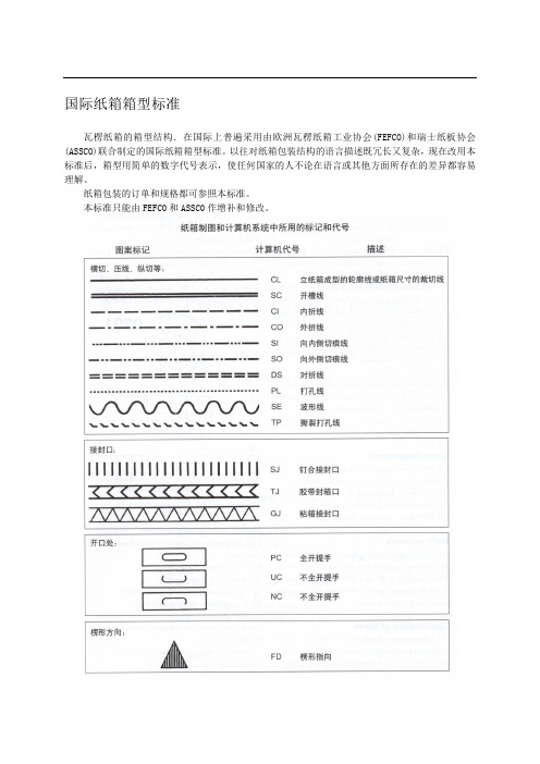
国际纸箱箱型标准瓦楞纸箱的箱型结构.在国际上普遍采用由欧洲瓦楞纸箱工业协会(FEFCO)和瑞士纸板协会(ASSCO)联合制定的国际纸箱箱型标准。
以往对纸箱包装结构的语言描述既冗长又复杂,现在改用本标准后,箱型用简单的数字代号表示,使任何国家的人不论在语言或其他方面所存在的差异都容易理解。
纸箱包装的订单和规格都可参照本标准。
本标准只能由FEFC0和ASSC0作增补和修改。
本标准下的系统结构为纸箱内部视图纸箱规格尺寸除非另有规定,所有纸箱内径尺寸都以毫米为单位表示如下:长度(L)×宽度(B)×高度(H)其中,长度(L)=开口处最长的尺寸宽度(B)=开口处最短的尺寸高度(H)=从开口处至箱底水平面的尺寸长度、宽度和高度的规格尺寸在纸箱结构说明中都作了明确规定,在某些箱型中其宽度要大于长度。
测定纸箱尺寸,必须在规定的标准气候条件下进行,在平铺的纸板上从压线中心处开始.同时注意量具本身的厚度。
对于罩盖型纸箱,罩盖的高度(h)可在斜线后用第四尺寸表示,即355 X 205×120/40毫米(L) (B) (H) (h)对于搭口外部摇盖纸箱,搭口(o)区域的长度可在斜线后用第四尺寸表示,即355×205×1 20/40毫米(L) (B) (H) (o)纸板规格尺寸除非另有规定,所有瓦楞纸板尺寸都以毫米为单位表示如下:第一尺寸×第二尺寸其中,第一尺寸=沿胶缝的长度第二尺寸=垂直于胶缝的长度纸箱式样某些纸箱类型衍生自同种式样,因而无需就此类型另行规定。
但是在表示基本箱型式样的数字后面需添加一个后缀数字.并用破折号隔开,如0201—2。
具体到每个生产商,这样的式样标准可能会略有不同。
纸箱式样组合下图所示的纸箱结构式样为纸箱的基本类型。
若纸箱的结构为两种或三种基本类型的组合,如摇盖组合,也同样可以表示为:上摇盖0204,下摇盖0215 这样的式样还可以表示为O204/O215(上摇盖/下摇盖)。
出口商品瓦楞纸箱检验标准要求及注意事项
出口商品瓦楞纸箱检验标准要求及注意事项化倾向日益走强。
目前我国商品的主要出口国家和地区包括美国、欧盟国家、日本、韩国及东南亚国家等,而这些国家大多是世界贸易组织贸易与环境委员会成员,也是绿色贸易保护主义最为盛行的地区,针对进口商品包装都制定了一系列的标准与法规,旨在保证商品的运输安全性,保护消费者安全及自然环境。
在出口商品使用的包装材料中,瓦楞纸箱由于使用方便、成本相对低廉,强度也能够满足各类产品的包装要求,因此占据着十分重要的地位。
出口商品生产企业及其瓦楞纸箱供应商应对我国及主要出口国的出(进)口商品瓦楞纸箱检验标准保持高度关注,避免因瓦楞纸箱不符合要求而影响商品的出口贸易。
我国出口商品瓦楞纸箱检验标准目前我国出口商品瓦楞纸箱检验所依据的标准是《出口商品运输包装瓦楞纸箱检验规程》(SN/T 0262-1993),该标准规定了出口商品瓦楞纸箱的技术要求、检验项目、抽样与检验方法,适用于海运、陆运及空运出口商品包装用单瓦楞、双瓦楞纸箱的检验。
该标准按照内装物最大重量、最大内综合尺寸(即纸箱长、宽、高总和)及使用瓦楞纸板的种类,将瓦楞纸箱分为8种,如表1所示。
表1 SN/T 0262-1993中出口商品瓦楞纸箱的分类容包括外观检验、性能检验及型式检验。
(1)外观检验①标志:标志的相关要求应依照《包装储运图示标志》执行,同时瓦楞纸箱上还应印有商检部门规定的代码和代号。
②印刷要求:瓦楞纸箱箱面上印刷的图案、文字应清晰正确、深浅一致、位置准确。
③压痕线:单瓦楞纸箱的压痕线宽度不大于12mm,双瓦楞纸箱的压痕线宽度不大于17mm;折线居中,不得有破裂、断线、重线等缺陷,瓦楞纸箱上不得有多余的压痕线。
洞直径不超过5mm。
⑤箱钉:箱钉应使用带有镀层的低碳钢扁丝,不应有锈斑、剥层、龟裂或其他使用上的缺陷;间距均匀,单钉距不大于55mm,双钉距不大于75mm;首尾钉至压痕边线的距离为(13±7)mm;钉合接缝处应钉牢、钉透,不得有叠钉、翘钉、不转脚钉等缺陷。
en 50577标准
en 50577标准
摘要:
1.EN 50577 标准的概述
2.EN 50577 标准的主要内容
3.EN 50577 标准的应用领域
4.EN 50577 标准的重要性
正文:
EN 50577 标准是欧洲标准之一,全称为“建筑产品- 硬质合金- 瓦楞纸板和纸箱- 测定静态弯曲强度和堆码强度的试验方法”。
这个标准主要规定了硬质合金瓦楞纸板和纸箱的静态弯曲强度和堆码强度的测定方法。
静态弯曲强度是指纸板或纸箱在静态状态下,能够承受的最大弯曲应力。
堆码强度则是指纸板或纸箱在堆放过程中,能够承受的最大压力。
这两个指标是衡量纸板和纸箱质量和耐用性的重要参数,对于包装设计、物流运输等领域有着重要的指导意义。
EN 50577 标准的主要内容分为两部分,第一部分是试验方法,包括静态弯曲试验和堆码试验。
第二部分是试验设备和试验过程的要求,包括试验设备的精度、试验过程的环境条件等。
EN 50577 标准的应用领域主要在包装行业和物流行业。
包装行业需要按照这个标准来设计和生产纸箱,以保证包装的强度和耐用性。
物流行业则需要按照这个标准来检测运输过程中包装的强度,以保证物流的顺利进行。
瓦楞纸板边压强度标准
瓦楞纸板边压强度标准
瓦楞纸板边压强度标准是指瓦楞纸板在边压作用下所能承受的最大压力。
根据不同国家或地区的标准和行业规范,瓦楞纸板边压强度标准可以有所不同。
以下为一些常见的标准和规范:
1. 美国标准:根据TAPPI(Technical Association of the Pulp
and Paper Industry)T811标准,瓦楞纸板的边压强度测试方法
为Mullen方法,标称值的单位为磅每平方英寸(psi)。
2. 欧洲标准:根据FEFCO(European Federation of Corrugated Board Manufacturers)的标准,欧洲瓦楞纸板的边压强度以BF 或BE值来表示,其单位为纸糊板厚度的倍数。
例如,BE槽
瓦楞纸板表示其边压强度为1倍纸糊板厚度。
3. 中国标准:根据GB/T(中华人民共和国国家标准)的标准,中国瓦楞纸板的边压强度采用单板边压法进行测试,以最大承载压力为标准进行评定。
标准中规定了不同等级的边压强度要求。
需要注意的是,瓦楞纸板的边压强度标准主要会根据瓦楞纸板的结构、纸板的质量和用途等因素进行设定,具体标准可能会根据不同行业需求和产品特性进行调整。
出口商品瓦楞纸箱检验标准要求及注意事项

出口商品瓦楞纸箱检验标准要求及注意事项化倾向日益走强。
目前我国商品的主要出口国家和地区包括美国、欧盟国家、日本、韩国及东南亚国家等,而这些国家大多是世界贸易组织贸易与环境委员会成员,也是绿色贸易保护主义最为盛行的地区,针对进口商品包装都制定了一系列的标准与法规,旨在保证商品的运输安全性,保护消费者安全及自然环境。
在出口商品使用的包装材料中,瓦楞纸箱由于使用方便、成本相对低廉,强度也能够满足各类产品的包装要求,因此占据着十分重要的地位。
出口商品生产企业及其瓦楞纸箱供应商应对我国及主要出口国的出(进)口商品瓦楞纸箱检验标准保持高度关注,避免因瓦楞纸箱不符合要求而影响商品的出口贸易。
我国出口商品瓦楞纸箱检验标准目前我国出口商品瓦楞纸箱检验所依据的标准是《出口商品运输包装瓦楞纸箱检验规程》(SN/T 0262-1993),该标准规定了出口商品瓦楞纸箱的技术要求、检验项目、抽样与检验方法,适用于海运、陆运及空运出口商品包装用单瓦楞、双瓦楞纸箱的检验。
该标准按照内装物最大重量、最大内综合尺寸(即纸箱长、宽、高总和)及使用瓦楞纸板的种类,将瓦楞纸箱分为8种,如表1所示。
表1 SN/T 0262-1993中出口商品瓦楞纸箱的分类容包括外观检验、性能检验及型式检验。
(1)外观检验①标志:标志的相关要求应依照《包装储运图示标志》执行,同时瓦楞纸箱上还应印有商检部门规定的代码和代号。
②印刷要求:瓦楞纸箱箱面上印刷的图案、文字应清晰正确、深浅一致、位置准确。
③压痕线:单瓦楞纸箱的压痕线宽度不大于12mm,双瓦楞纸箱的压痕线宽度不大于17mm;折线居中,不得有破裂、断线、重线等缺陷,瓦楞纸箱上不得有多余的压痕线。
洞直径不超过5mm。
⑤箱钉:箱钉应使用带有镀层的低碳钢扁丝,不应有锈斑、剥层、龟裂或其他使用上的缺陷;间距均匀,单钉距不大于55mm,双钉距不大于75mm;首尾钉至压痕边线的距离为(13±7)mm;钉合接缝处应钉牢、钉透,不得有叠钉、翘钉、不转脚钉等缺陷。
国外瓦楞纸标准

国外瓦楞纸标准瓦楞纸是一种由纸板制成的材料,具有波纹状的表面结构。
它被广泛应用于包装箱、纸箱和其他包装材料中。
在国外,不同的国家和地区都有各自的瓦楞纸标准,以确保包装材料的质量和性能。
本文将介绍几个国外常见的瓦楞纸标准。
一、德国DIN标准德国DIN标准是一种常用的瓦楞纸标准。
根据DIN 55468标准,瓦楞纸被分为七个等级,从K1到K7。
K1是最轻的瓦楞纸,适用于较轻的包装材料,如文具和电子产品的包装。
而K7是最重的瓦楞纸,适用于重型物品的包装。
此外,DIN标准还考虑了瓦楞纸的抗湿性和抗撕裂性能,以确保包装的质量。
二、美国ECT标准美国ECT(Edge Crush Test)标准是一种常用的瓦楞纸标准。
根据ECT标准,瓦楞纸的质量和强度通过测量边缘抗压强度来评估。
ECT值越高,瓦楞纸的强度越高,适用于承受较大压力的包装。
根据美国联邦包装协会(FPAA)的规定,ECT标准分为三个等级:单壁(ECT32)、双壁(ECT44)和三壁(ECT55)。
而ECT标准并不考虑瓦楞纸的抗湿性能,因此在潮湿环境下可能不适用。
三、国际ISO标准国际ISO(International Organization for Standardization)标准是一种被广泛应用于国际贸易的瓦楞纸标准。
按照ISO 2022标准,瓦楞纸被分为三个等级:A、B和C,其中A是最轻的瓦楞纸,适用于轻型包装,C是最重的瓦楞纸,适用于重型包装。
此外,ISO标准还考虑了瓦楞纸的湿强度和湿抗撕裂性能,以确保包装在湿润环境中的使用。
四、英国等级标准在英国,瓦楞纸标准通过根据瓦楞波浪高度来进行分类。
标准分为C波高、B 波高、E波高和F波高四个等级。
其中C波高适用于较轻型的包装,F波高适用于较重型的包装。
英国等级标准还考虑了瓦楞纸的抗湿性,以确保包装在湿润环境中的性能。
总结起来,国外的瓦楞纸标准包括德国DIN标准、美国ECT标准、国际ISO 标准和英国等级标准。
瓦楞纸欧洲标准
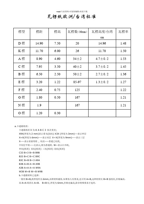
瓦楞数(30cm) 瓦楞高度/台湾
cm
20
14.96
瓦楞率 1.48
26 34±2
11.70
1.50
பைடு நூலகம்
4.7±0.2
1.53
40±2 50±2 85-97
3.7±0.2
1.45
2.7±0.2
1.36
1.3±0.2
1.27
125
1.22
167
1.21
167
1.21
a.卡通箱纸质: 卡通箱纸质 X 为:K A B C 3 依次变差; X9X(厚度为 2 mm)表示 E 坑(幼坑) X3X (厚度为 3mm)---表示单层 X=X(厚度为 6mm)----表示双层 X≡X(厚度为 9mm)----表示三层 X----表示表面用纸 , 坑纹----普通之坑纸, 中间层平纸----无表示,则为普通纸. W—表示白书纸, 单坑(纸质) 双坑(纸质) 三坑(纸质) 幼坑(纸质) C33 B=3 B≡B B9B B33 B=C B≡C B9C B3C B=B B≡3 A9A B3B A=B A≡B A9B A3B A=A A≡A W9A W3B W=B W≡B W9B b.卡通箱材料之选择: 一般用 B=B,纸厚度约为 6mm,该种材料最低.如果客人有要求,也可用 A=B,这种材质比 B=B 强度好,价格偏高, 而 A=A 纸质比 A=B、 B=B 好,厚度为 6mm,价格也偏高,除非特殊要求才选用.
英制公制单位换算表项目英制单位公制单位英制换公制公制换英制长度inchescentimetersmillimeters1in254cm1in254mm1cm0394in1mm0039in重量poundskilograms1lb0454kg1kg2205lbspoundhsfgramssquaremeter1lbmsf4882gm1gm0205lbsmsf面积squareinchsquaremetermsin064516m1m1550in速度feetminutemeterminute1feetmin0305mmin1mmin328ftmin温度degreesfahrenheitdegreescelsius59f32c95c32f破裂强poundssquareinchkilopasoalskgfsquareoentimeters1psi6895kpa1kgfcm98066kpa1kgfcm142psi1kpa0145psi1kpa0010kgfcm竖压强inchkilonewtonmeter1lbin0175knm1knm5714lbsin冲孔强inchouncesinchtearjoules1inozin0030j1j33333inozin
澳大利亚、新西兰瓦楞纸箱测试标准

澳大利亚、新西兰瓦楞纸箱测试标准2002──瓦楞纸板平压强度测试瓦楞纸板平压强度测试标准是由联合技术委员会起草的,专门针对纸浆和纸张的测试。
是纸浆和纸张测试方法(AS/NZS1301)的一部分。
该版本替代旧标准:AS1301.429s-1989和NZS1301.429s-1989。
该标准用于测试瓦楞纸板的抗压强度。
适用于三层或单面瓦楞纸板,但不适用于测定五层瓦楞纸板的抗压强度。
(注:三层瓦楞纸板楞型变形可能发生于以下两种情况:当压力不能从纸板边缘释放时,楞峰变平,从而导致楞型遭到破坏;当压力能从纸板边缘释放时,楞峰变平,表层面纸移位,使芯纸歪斜或卷曲。
五层瓦楞纸板受压时楞型遭到破坏,通常是由于中间层的面纸边缘移位。
现在还没有研究出方法队止这种状况发生,因此,该测试不适用于五层瓦楞纸板。
)如果采用垂直于纸板表面的力测试瓦楞纸板的抗压强度,可以测定纸板的平压强度。
尽管该测试与瓦楞纸箱的抗压强度无直接关系,却是测定与影响纸板纤维结构的联合测试,也可以测定瓦楞纸板的原材料的质量。
低抗压强度值表明瓦楞纸板结构差、原材料不达标或是达标的原材料在经过加工后遭到破坏。
这些破坏可能发生在纸箱加工厂内的加工工序中(如在印刷时受到挤压)或者是由于储存不当,或是使用者处理不当遭到破坏。
出于这种考虑,在挑选纸板样本用于测试时必须特别注意,确保测试的样本能反映纸板的真实状况,或对于低测试值能做出合理的解释。
该方法允许使用固定的压盘或其它测量用具,在测试中,可以使用持样板工具,以防止测试样板在受压时发生边移动。
如果使用固定压盘话,则不一定需要使用持板工具。
在这种情况下,被测试纸板通常发生边缘爆裂,这被认为是纸板的一种特性,可以将此测试结果作为平均值记入报告中。
单面纸板和三层纸板平压强度测定方法,其它类似的标准包括:TAPPI T808om-01;TAPPIT825om-96;EN23035-98 和BS4686-1971。
AS/NZS 1301.434s-1997──瓦楞芯纸的抗压强度测试瓦楞芯纸的抗压强度测试用于测定瓦楞纸板的抗压强度。
欧洲废纸标准

欧洲废纸,纸版标准等级表February 1999本文件作为1995年1月CEPI的等级表的修正版,由欧洲纸工业协会(CEPI)和国际再生物资局(BIR)联合制定。
前言本表根据废纸内所含有和不含有的种类基本定义了废纸的等级标准。
本表供造纸工业的专业人士及热衷于采集废纸并帮助购买及销售这一板纸工业计划回收的原料的相关组织与个人使用。
本表同时将对那些被要求在不同国家的立法对废物流动的控制有差异的前提下需要将原料和废物区分开来的海关及税务局官员提供了支持和帮助。
我们的目的不是把所有存在于不同市场上的所有废纸分类,而是把在欧洲市场上通常交易的品质加以定义。
关于等级的描述是简单的,就此原因我们认为供应商和买方之间关于有特殊指标的等级的特殊交易条款将仍是必须的,这能满足单独的条款要求。
并不会被与本表有关的任何规则排除在外。
板纸工厂可能会要求由供应商处提供原料的原产地证明,为国内的相关法规或标准的要求。
从废纸分类站剔选出来的废纸是不适于纸厂使用的。
回收的纸和纸板来源于多种物质回收系统,只含有有价值的原料,可循环的种类,必须被特别标明,不加标签混装在其他回收纸板中是不允许的。
本表列有一组回收纸等级(第5组"特殊"等级),在很多情况下,只能经过特定的程序回收,否则将会对循环再生造成一些特别的限制。
它们在本表所列含有物已被欧洲市场证实。
实际上的这些物质特殊品种的再生只能在分布在少数几个国家内的有限的几个工厂才能完成。
定义不能使用的物质不能在纸及纸板的生产中使用的原料含有非纸成份和对生产有害的纸及纸板,回收的纸及纸板应该基本上在供应时应该不含上述物质,单在针对特殊等级而言,买卖双方同意有一定比例的不可用物质,这只需要参考其成分,被称为:对生产有害的纸及纸张。
非纸成分这是指回收后的纸及纸板中所含的任何异物,它们在生产中会损坏机器,或中断生产,或降低最终成品的价值,如:-金属-塑料-玻璃-纺织品-木材-砂子和建筑材料-合成物质-合成纸对生产有害的纸及纸板有一种等级的纸和纸板在回收和处理后,对基本或标准水平的设备来说,无法被用来作为原料制造纸及纸板,否则会形成损坏或则由于其存在而导致所有该批次的无法使用。
FEFCO 欧洲瓦楞纸箱测试标准
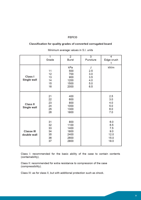
FEFCOClassification for quality grades of converted corrugated board Minimum average values in S.I. units1 Grade2Burst3Puncture4Edge crushtClass I Single wall 111213141516kPa500700900120015002000J2.53.03.54.05.06.5kN/mClass II Single wall 2122232425264006008001000130018002.53.04.05.06.07.0Classe III double wall 313233343536378001100140018002400260028006.06.57.59.012.015.018.0Class I: recommended for the basic ability of the case to contain contents (containability).Class II: recommended for extra resistance to compression of the case (compressibility).Class III: as for class II, but with additional protection such as shock.CONTROL PROCEDURE FOR THEUSE OF FEFCO CLASSIFICATION FORCORRUGATED BOARD QUALITIES1. All companies are entitled to use the FEFCO quality stamp. But if they doso they must agree to respect the rules as set down by FEFCO being the owners of the stamp.2. In advance the companies using the stamp guaranty that the packagingthey supply is in conformity with the above mentioned rules. For each specification the board shall be tested according to the relevant FEFCO testing method.3. The above mentioned tests shall be done on a regular basis in order toensure permanent conformity.4. FEFCO appoints official laboratories to ensure neutrality in control.5. In case of dispute concerning the conformity of packaging the customercan ask for tests to be performed by the appointed laboratory.6. In case of non-conformity to the stamp and its rules a report will be sent tothe supplier and to FEFCO.7. The manufacturer is allowed to ask for a second series of tests.8. Being given that FEFCO is responsible for the stamp and its qualitycontrol procedure the federation can intervene to put an end to any abuse or bad utilisation of same. To be followed by appropriate measures.9. In case parties involved cannot settle their dispute FEFCO has the right tomake a final decision which shall be binding to both parties.1050 Brussels Fax: +32 2 646 6460Twitter @FEFCO | @Corrugated_OCIntroduction to the developmentof FEFCO Testing Methodsfor corrugated board and boxesThe Testing Methods n°1 - 7 were officially issued following the approval by national organisations, by the FEFCO General Assembly at the Vienna Congress on 29th April 1966. Since then new Testing Methods were introduced in 1968, 1971 and 1973.The Standards Committee of FEFCO proposed in 1982 to the FEFCO Board to follow several organisations in changing the testing conditions from 20°C and 65 % RH into 23°C and 50 % RH as being a world-wide standard. The approval of the proposal by the Board of FEFCO in 1983 meant consequently that the Testing Methods had to be revised.Doing this the Standards Committee took the opportunity to improve several Testing Methods to a better working level based on the experience with the methods during the past years.Since 1990 some of the Testing Methods have been amended again in order to be in line with the ISO and EN test methods as these cover the same purpose and have been internationally accepted.Altogether this leads to a complete new publication of the Testing Methods. FEFCO intends to pursue its responsibility for improving and developing Testing Methods both on corrugated board and corrugated cases.It is intended that these Testing Methods should be selectively applied, either singly or in combination with others in the series, as may be called for in the FEFCO Classification and/or in National Specifications and Regulations.Regular checking to improve method and instruments will be part of the FEFCO Test Round with the national laboratories. The application of these Testing Methods with the standardisation of instruments and processes to be used in individual laboratory tests will contribute towards providing an ever improving guarantee of the specific characteristics of corrugated board and containers and will engender increasing confidence in the employment of such material in the packaging field throughout Europe. sTo define a procedure for sampling from a batch of corrugated fibreboard in sheets, or from corrugated containers, for the purpose of obtaining a representative sample for testing. The test is applicable to all kinds of corrugated fibreboard.From each batch a number of bundles or pallets will be selected at random. Random means that any item shall have an equal chance of being selected as part of the sample . From each of the bundlesor pallets a specified number of individual samples will bepicked. From individual samples the test specimens for thevarious tests will be cut with adequate dimensions.A batch is a quantity of corrugated fibreboard of one sort or typewhich may be considered homogeneous, and may consist of one or several bundles or pallets.A sample is the total number of individual samples from onebatch.An individual sample is a sheet of corrugated fibreboard, or acase, taken from a bundle or pallet.A test specimen is a piece of corrugated board cut from anindividual sample.Determination of the total number of individual samplesThe number of individual samples to be taken, as a minimum, from a batch will be determined by the formula :n = 3√N Where:n = total number of individual samples, andN = total number of sheets or cases in the batch.For convenience, the following table may be used:N n1,000 or less 101,001 to 5,000155,001 to 10,0002010,001 to 20,0002520,001 to 30,0003030,001 or more 40(the minimum in any case will thus be 10, and the maximum 40).Selection of individual samples Each of the bundles or pallets selected according to Clause 3 will be handled as follows :After removal of the wrapping or strapping materials at least five topmost sheets or cases will be eliminated. Thereupon, so many individual samples will be picked at random from the bundles or pallets that the total number of individual samples thus obtained from the batch will equal « n » as defined in Clause 3.1. An approximately equal number of individual samples shall be taken from each bundle or pallet selected.Handling of individual samples Keep the samples flat, without compression, and protect them from direct sunlight, liquids, or anything liable to alter their condition.Marking of samples Individual samples will be marked in a corner in such a manner as to ensure perfect identification.Repeated sampling If repeated sampling is necessary, it will be done in accordance with the method. Unless it is otherwise specified, and if it is possible, samples shall not be taken from bundles or pallets which have been used for the first sampling.The report will contain the following information :Date and place of sampling Inspector’s name Manufacturer’s name Size of batch Number and type of bundles or pallets Number of individual samples pursuant to clause 3.1.Identification marks on the samples Details of any deviation from this sampling method Any other information which may assist in the evaluation of the sample.43211July 1984Sampling procedureTo define the apparatus and procedure used to determine the basis weight of corrugated fibreboard for packing cases bearing the manufacturer’s certificate. The test is applicable to all kinds of corrugated fibreboard.FEFCO testing method n°1 : sampling procedureEN 20 187 : paper, board and pulps - Standard atmosphere for conditioning and testing and procedure for monitoring the atmosphere and conditioning of samples.Test specimens of given area, taken from a representative sample of corrugated fibreboard, are brought into equilibrium with a standard atmosphere and are then weighed on a suitable accurate balance.Test results (basis weights) are expressed in g/m 2.A balance with sensitivity of 0.5 g, or better, over the entire measuring range, shall be used to make the determinations.Sample in accordance with FEFCO Testing Method N°1.The samples shall be conditioned in accordance with EN 20 187(i.e. 23°C ±1C°, 50 % ±2% r.h.).Representative samples from corrugated fibreboard to be tested shall be large enough to permit the cutting of test specimens of 500 cm2 area (200 mm ±0.5 mm x 250 mm ±0.5 mm).Test specimens shall be free from machine marks and other irregularities ; the surface must be free from printing or other treatments which may affect the weight ; and the edges must be cut clean and square.The testing shall be carried out in the standard atmosphere,defined in Clause 6.Each test specimen will be separately weighed and the weight recorded to the nearest 0.5 g.Unless otherwise stipulated, at least ten determinations are to be made.For each determination the basis weight will be calculated by the formula:g x 106G =–––––––––––a x b Where :G = basis weight in g/m 2g = weight of test specimen in g a = length of test specimen in mm b = width of test specimen in mm The test report will contain the following details :Date and place of testing Description and identification of the product tested Results of individual tests to the nearest g/m 2Arithmetic mean and standard deviation of all the replicate tests Details of any deviation from this testing method Any other information which may assist in the interpretation of the test results.10 98 7654321Determination of the basis weight of corrugated fibreboardTo define the apparatus and test procedure to measure the thickness (calliper) of corrugated fibreboard used in packing cases bearing the manufacturer’s certificate. The test is applicable to all kinds of corrugated fibreboard. This method is applicable to all types of corrugated fibreboard .FEFCO testing method n°1 : sampling procedureEN 20 187 : paper, board and pulps - Standard atmosphere for conditioning and testing and procedure for monitoring the atmosphere and conditioning of samples.The thickness (calliper) of corrugated fibreboard is the distance in millimetres measured between two plane parallel faces of a micrometer, between which the test specimen is subjected to a specified pressure.The measuring apparatus shall be a dead-weight dial gauge micrometer with a plane circular anvil and a concentric plane plunger. The area of the anvil and of the plunger shall be 10 cm 2±0.2 cm 2.The measuring surfaces shall be parallel within 0.001 of their diameter, and the dead-weight loading of the plunger shall be 20 ±0.5 kPa.The instrument shall be sufficiently accurate to permit measurement to be made to the nearest 0.05 mm.Sample in accordance with FEFCO Testing Method N°1.Samples shall be conditioned accordance with EN 20 187 (i.e.23°C ±1°C, 50 % ±2 % r.h.).Individual samples selected from the batch must be large enough to permit the cutting of test specimens with an area of 500 cm 2(200 mm x 250 mm). Test specimens must be free from converting machine marks, damage, or other irregularities.The testing shall be carried out in the standard atmosphere defined in clause 6.The plunger is to be lowered slowly, without impact.Two measurements are to be made on each test specimen, at least 50 mm from an edge, and at least ten test specimens shall be measured.The test report will provide the following information :Date and place of testing Description and identification of the material tested Number of individual measurements Arithmetic mean of all measurements in millimeters Details of any deviation from this testing method Any other information which may assist in the interpretation of the test results ; in particular whether any areas compressed by printing or converting machines are involved.Recommendations :the measuring capacity of the dead-weight dial gauge micrometer should be at least 20 mm.The depth of throat of the micrometer should be not less than 50 mm.98 7654321Determination of the thickness (calliper)of corrugated fibreboardNovember 1994 (amended March 1997)Determination of the bursting strength of corrugated fibreboardTo define the apparatus and test procedure used to determine the bursting strength of corrugated fibreboard. The test is applicable to all kinds of corrugated fibreboard.FEFCO testing method n°1 : sampling procedureEN 20 187 : paper, board and pulps - Standard atmosphere for conditioning and testing and procedure for monitoring the atmosphere and conditioning of samples.The test specimen of corrugated fibreboard is firmly clamped between annular surfaces and uniformly increasing pressure is applied to one side, by pumping liquid under a flexible diaphragm,over a circular free testing area, until the specimen bursts.The maximum pressure sustained by the specimen is recorded.Type of Burst TesterA hydraulic motor-driven burst tester shall be used.Clamping DeviceThe burst tester must be fitted with a clamping device in which test specimens can be held without damage, other than crushing of the flutes, and without slippage, whilst the test is carried out.The clamping pressure shall be measurable.Clamping RingsThe internal diameter of the upper and lower clamping rings shall be 31.5 mm ±0.1. mm.The edges of the clamping surfaces shall be slightly rounded. The rings shall be strong enough to withstand the clamping stresses without deformation.The internal edge at the lower face of the lower clamping ring shall be rounded, to prevent damage to the diaphragm.The clamping surfaces must be flat and should have circular or spiral grooves 0,2 mm to 0,5 mm deep to increase clamping efficiency.The clamping rings must be mounted parallel, and accurately centred.Diaphragm The diaphragm shall be made of highly elastic material, should be clamped securely with its upper surface about 5.5 mm below the top plane of the lower clamping plate and have the following distension / load properties :Bulge height Pressure range 10 mm 170 to 220 kPa 18 mm 250 to 350 kPa Pumping rate The pressure under the diaphragm shall be produced by an electro-hydraulic pump delivering technically pure, air-free glycerine, or other suitable liquid with analogous properties, at a rate of 170 ±15 ml per minute.Pressure measurement The total measuring capacity shall extend from 0 to 5000 kPa.Pressure measuring devices shall be fitted with the means to record maximum value.Those devices shall be calibrated Sample in accordance with FEFCO Testing Method N°1.The samples shall be conditioned in accordance with EN 20 187(i.e. 23°C ±1°C, 50 % ±2% r.h.).A sufficient number of representative samples of the corrugated fibreboard to be tested shall be available to permit the stipulated number of replicate tests to be carried out without overlap of the clamped areas. For convenience of handling, the board may be cut into specimens 150 mm x 250 mm ; this will allow one test from each side of each specimen . 7654321The testing shall be carried out in the standard atmosphere defined in clause 6.The specimen is placed in the clamping device and clamped with a pressure not less than 700 kPa.The maximum reading device is set to zero and the tester operated until the specimen bursts.Test results should be recorded to 3 significant figures.Unless otherwise stipulated, 10 tests are to be made from each side of the corrugated fibreboard.The test report should contain at least the following points :Date and place of testingReference to this FEFCO testing methodDescription and identification of the product tested Value of each testArithmetic mean and standard deviation of all replicate test resultsClamping pressure in kilopascalDetails of any deviation from this testing methodAny other information which may help in the interpretation of the test resultsName and signature of the operator.985July 1985 (reapproved and improved version of 1966)Determination of the puncture resistanceof corrugated fibreboardTo define the apparatus and test procedure use to determine the puncture resistance of corrugated fibreboard used in packing cases bearing the manufacturer’s certificate. The test is applicable to all kinds of corrugated fibreboard.FEFCO testing method n°1 : sampling procedure.EN 20 187 : paper, board and pulps - Standard atmosphere for conditioning and testing and procedure for monitoring the atmosphere and conditioning of samples.A representative sample of corrugated fibreboard is subjected to puncture by a triangular pyramid puncture head attached to a pendulum.The energy required to force the puncture head completely through the sample i.e. - to make the initial puncture, and to tear and bend open the fibreboard - is measured in J (N.m).Type of puncture testerThe instrument to be used produces an impact by means of a pendulum. The bed plate of the frame of the instrument must be firmly attached to a strong base to prevent energy losses. The instrument must be accurately levelled, and it must not vibrate during the test.The instrument must be so designed that the energy contained in the pendulum in each of the measuring ranges corresponds to the respective scale. This condition is the responsibility of the instrument manufacturer to whom appeal shall be made if there is any doubt as to the accuracy of the instrument, particularly if it is suspected that changes have occurred in the distribution of the pendulum, including the supplementary weights.Pendulum and puncture headThe pendulum shall be fitted with an arm, having the shape of a 90°circular arc, to which the puncture head is attached. Both pendulum and arm must be strong enough to preclude deformation and to minimise vibration when the test is carried out.The puncture head shall be a triangular, height 25.0 ±0.7 mm the edges of which, meeting at the vertex, form right angles. All edges between sides are to be rounded off, radius = 1 mm.One of the edges of the base of the pyramid shall be parallel to the axis of rotation of the pendulum, and the opposite corner of the base shall point towards the axis of rotation.The axis through the effective point of the puncture head shall be vertical when its mid-point passes through the horizontal plane through the axis of the pendulum. [1].At release point the pendulum shall be in the horizontal position,which is determined by measuring through an angle of 90°from the pendulum with its centre of gravity at rest.Measuring rangesBy the use of interchangeable weights which can be attached to the pendulum, several ranges of energy are to be provided.The range selected should be such that the test result will be between 20 % and 80 % of the maximum value of the corresponding scale.Release mechanismA safety catch must be provided to prevent accidental release of the pendulum. The release mechanism must not impart any acceleration or deceleration to the pendulum.CollarThe neck of the puncture head shall be fitted with a close fitting collar designed so as to slip off its seating and to keep open the aperture in the test specimen after the puncture head has passed through.This is to prevent the fibreboard from springing back on the arm and braking the pendulum, thus altering the test result.The loss of energy due to friction when the collar is forced off its seating shall be measurable and shall not exceed 0.25 J. This loss of energy shall be compensated for in the reported test result.Clamping deviceTo hold the test specimen, two horizontal clamping plates shall be provided, the upper plate being fixed. The lower face of the upper clamping plate -which contacts the test specimen- shall be on the horizontal plane through the axis of the pendulum, or up to 7 mm above it.Both clamping plates must be sufficiently rigid to withstand the clamping forces employed, without deformation.[1]To permit the use of existing instruments, the axis through the effective point of the puncture head may be vertical when its mid-points is within ±12.5 mm of the horizontal plane through the axis of the pendulum.4321The effective clamping dimensions of the clamping plates shall be not less than 175 mm x 175 mm.The upper clamping plate shall have a centrally positioned regular triangular aperture with sides 100 mm ±2 mm in length. Whilst it is recommended that the aperture in the lower plate should be identical and coincident with that in the upper plate, a centrally positioned circular aperture, with a diameter 90 mm ±2 mm, is permissible. [2].Clamping forceThe force holding the test specimen between the clamping plates shall be at least 400 N and not more than 1000 N. If the instrument has no device for measuring the clamping force, the force applied must in any case be sufficient to ensure that the test specimen does not slip when the test is carried out.Indication of the measured resultThe test result shall be indicated by a peak-indicator, e.g. a friction loaded pointer operating over a dial on which the several scales, corresponding to the energy ranges, are engraved. The scale divisions should be calibrated in J (N.m).In case of a friction loaded pointer, the friction mounting of the pointer should be sufficient to ensure smooth operation without over-run.Adjustment of the instrumentFor all measuring ranges the effective point of the puncture head shall be within ±5 mm of the horizontal plane through the axis of rotation of the pendulum, when the centre of gravity of the pendulum is at its lowest point.Instrument checksNo compensation for loss of energy due to friction should be made in the calibration of the measuring scales.Energy loss due to friction in the bearings of the pendulum and air resistance must not exceed 1 % of the measuring scale.To measure energy loss due to collar friction a slip-off device must be provided which catches the collar when the pendulum is allowed to swing freely from the release point.Energy losses due to pointer friction shall be determined by allowing the pendulum to make two free swings from the release position. The first swing should carry the pointer close to the scale zero. The second free swing, made without resetting the pointer, should carry the pointer nearer to the zero reading. The difference between the two readings will represent the energy loss due to pointer friction.When making readjustments to the settings of the measuring scales the following checks should be made:Allow the pendulum to come to rest, with its centre of gravity at the lowest point, then move the pointer towards the maximum scale value. If, in the position, the drive pin of the pendulum just touches the pointer, the setting is correct. An analogous check should be carried out with the pendulum in the horizontal position, 180°from the release point, when the pointer should indicate zero.Sample in accordance with FEFCO Testing Method N°1.[2]To permit the use of certain existing types of instruments, the lowerplate may have a centrally positioned circular aperture with a diameter up to 100 mm.Samples shall be conditioned in accordance with EN 20 187 (i.e. 23°C ±1°C, 50 % ±2 % r.h.).Test specimens with minimum dimensions 175 mm x 175 mm shall be prepared from a representative sample of the corrugated fibreboard to be tested. These test specimens must be free from conversion machine marks, irregularities, or damage. In no instance shall the puncture area be less than 60 mm from the edge of the sample, or from any crease, score, or printed area. If for some reason a printed area is used for the test, then this must be clearly stated in the test report.The testing shall be carried out in the standard atmosphere defined in clause 6.The test specimen will be placed between the clamping plates and clamped with a constant force which should be recorded if the instrument is equipped with a clamping force measuring device. The pendulum mass shall be adjusted, using the supplementary weights as necessary, to operate over the energy range which will contain the expected test result within 20 % and 80 % of its maximum value.The release mechanism shall then be operated and the puncture head will completely pierce and pass through the test specimen. The amount of energy used, representing the work in puncturing the test specimen is to be read from the appropriate scale. Scale readings should be to the nearest 0.1. J for the measuring ranges up to 12 J, and to the nearest 0.2 J for measuring ranges above 12 J.The test result shall then be compensated for predetermined energy losses caused by friction in the apparatus (pointer friction, forcing off the pyramid collar, etc).Unless otherwise stipulated, ten replicate tests are to be made from each side of the corrugated fibreboard ; five tests from each side with the flutes parallel with the axis of rotation of the pendulum ; and five tests from each side with the flutes at right angles to the axis of rotation of the pendulum.The test report will contain the following information :Date and place of testingDescription and identification of the material testedNumber of replicate tests carried outArithmetic mean of all the replicate test results in J (N.m)Standard deviation of the arithmetic mean in J (N.m)Clamping force in NDetails of any deviation from this testing methodAny other information which may assist in the interpretation ofthe test results.Interlaboratory tests showed, that the puncture resistance of corrugated boards tested in different laboratories may be assumed to be identical with a high degree of probability if the difference of the arithmetic mean is less than ca. 7 ... 8%.1098765To define the apparatus and test procedure used to determine the flat crush resistance of corrugated fibreboard used for packing cases bearing the manufacturer’s certificate.The test may be carried out on single face and double face (single wall) corrugated fibreboard. It is not suitable for testing the flat crush resistance of double-double face (double wall) board.FEFCO testing method n°1 : sampling procedureEN 20 187 : paper, board and pulps - Standard atmosphere for conditioning and testing and procedure for monitoring the atmosphere and conditioning of samples.A test specimen of corrugated fibreboard is subjected to a uniformity increasing force applied perpendicularly to the surface by a compression tester having two flat and parallel platens, until the fluting collapses.The maximum force sustained by the specimen is recorded.Type of flat crush testerA motor-driven type compression tester shall be used.If the tester operates on the principle of beam deflection the beam shall be such that the test results will occur within 20 % to 80 %of the normal range of deflection.PlatensThe platens must meet the following conditions :deviation from parallel not greater than 1:1000lateral play not exceeding 0.05 mmsize : 120 mm x120 mm to take 100 cm 2or 50 cm 2specimens.Note : the preferable size for beam tester is 50 cm 2.Relative speed and forceThe relative speed between the two platens shall be 12.5 mm ±2.5 mm per minute (with testers operating on the principle of beam deflection this is equivalent to an increment of force of 67 ±23 N per second when the platens are in contact with each other).Cutting instrumentAn instrument having a circularly guided knife to cut specimens with area of 100 cm 2(diameter 112.8 ±0.5 mm), or an area of 50cm 2(diameter 79.80 ±0.5 mm) shall be used. The cut edges must be clean and perpendicular to the facings of the board.Sample in accordance with FEFCO Testing Method N°1.Samples shall be conditioned in accordance with EN 20 187 (i.e.23°C ±1°C, 50 % ±2 % r.h.).Unless otherwise stipulated, at least ten specimens of the board shall be tested. They shall be free from converting machine marks,printing, or damage.The testing shall be carried out in the standard atmosphere defined above in clause 6 unless otherwise stipulated.The test specimen shall be placed centrally on the lower platen,and the tester operated until the fluting collapses.The maximum pressure sustained by the specimen before collapse of the fluting will be recorded to the nearest 10 kPa (kN/m 2).The test report will contain the following details :Date and place of testingDescription and identification of the product tested Results of individual tests to the nearest 10 kPa (kN/m 2)Arithmetic mean and standard deviation of all the replicate test resultsNumber of specimens with leaning flutes Details of any deviation from this testing methodAny other information which may assist in the interpretation of the test results.987654321July 1985 (improved version of 1966)Determination of the flat crush resistanceof corrugated fibreboard。
- 1、下载文档前请自行甄别文档内容的完整性,平台不提供额外的编辑、内容补充、找答案等附加服务。
- 2、"仅部分预览"的文档,不可在线预览部分如存在完整性等问题,可反馈申请退款(可完整预览的文档不适用该条件!)。
- 3、如文档侵犯您的权益,请联系客服反馈,我们会尽快为您处理(人工客服工作时间:9:00-18:30)。
瓦楞纸欧洲/台湾标准
楞型
楞距
楞高
瓦楞数(30cm)
瓦楞高度/台湾cm
瓦楞率
D楞
14.90
7.50
20
14.96
1.48
K楞
11.70
6.00
26
11.70
1.50
A楞
8.90
4.60
34±2
4.7±0.2
1.53
C楞
7.95
3.50
40±2
3.7±0.2
1.45
B楞6.502源自5050±22.7±0.2
1.36
E楞
3.20
1.22
85-97
1.3±0.2
1.27
F楞
2.40
0.75
125
1.22
G楞
1.80
0.50
167
1.21
N楞
1.9
0.40-0.50
167
1.21
O楞
1.20
0.30
a.卡通箱纸质:
卡通箱纸质X为:K A B C 3依次变差;
X9X(厚度为2 mm)表示E坑(幼坑) X3X (厚度为3mm)---表示单层
X=X(厚度为6mm)----表示双层X≡X(厚度为9mm)----表示三层
X----表示表面用纸,坑纹----普通之坑纸,
中间层平纸----无表示,则为普通纸. W—表示白书纸,
单坑(纸质)双坑(纸质)三坑(纸质)幼坑(纸质)
C33 B=3 B≡B B9B
B33 B=C B≡C B9C
B3CB=B B≡3 A9A
B3B A=B A≡B A9B
A3B A=A A≡A W9A
W3B W=B W≡B W9B
b.卡通箱材料之选择:
一般用B=B,纸厚度约为6mm,该种材料最低.如果客人有要求,也可用A=B,这种材质比B=B强度好,价格偏高,
而A=A纸质比A=B、B=B好,厚度为6mm,价格也偏高,除非特殊要求才选用.
Grams/square meter
1lb/MSF=4.882g/m²
1g/m²=0.205lbs/MSF
面积
Square inch
Square meter
MS.in=0.64516m²
1m²=1550in²
速度
Feet/minute
Meter/minute
1Feet/min=0.305m/min
1m/min=3.28ft/min
温度
Degrees
Fahrenheit
Degrees
Celsius
5/9(ºF-32)=ºC
9/5ºC+32=ºF
破裂强度
Pounds/Square
inch
Kilopasoals
Kgf/square
oentimeters
1psi=6.895kpa
1kgf/cm²=98.066kpa
1kgf/cm²=14.2psi
1kpa=0.145psi
1kpa=0.010kgf/cm²
竖压强度
Pounds/linoa
R inch
Kilonewton/meter
1lb/in=0.175KN/m
1KN/m=5.714lbs/in
冲孔强度
Inch ounces/
Inch of tear
joules
1in-OZ/in=0.030j
英制/公制单位换算表
项目
英制单位
公制单位
英制换公制
公制换英制
长度
Inches
Centimeters
Millimeters
1in=2.54cm
1in=25.4mm
1cm=0.394in
1mm=0.039in
重量
Pounds
Kilograms
1lb=0.454kg
1kg=2.205lbs
基重
Pound/HSF
