锤击成桩重锤低击轻锤重击桩头冲击力贯入度
锤击法

锤击法施工设备锤击法是利用桩锤的冲击克服土对桩的阻力,使桩沉到预定深度或达到持力层。
这是最常用的一种沉桩方法。
打桩设备包括桩锤、桩架和动力装置。
(1)桩锤桩锤是对桩施加冲击,将桩打入土中的主要机具。
桩锤主要有落锤、蒸汽锤、柴油锤和液压锤,目前应用最多的是柴油锤。
①落锤落锤构造简单,使用方便,能随意调整落锤高度。
轻型落锤一般均用卷扬机拉升施打。
落锤生产效率低、桩身易损失。
落锤重量一般为0.5~1.5t,重型锤可达数吨。
②柴油锤柴油锤利用燃油爆炸的能量,推动活塞往复运动产生冲击进行锤击打桩。
柴油锤结构简单、使用方便,不需从外部供应能源。
但在过软的土中由于贯入度过大,燃油不易爆发,往往桩锤反跳不起来,会使工作循环中断。
另一个缺点是会造成噪音和空气污染等公害,故在城市中施工受到一定限制。
柴油锤冲击部分的重量有2.0t,2.5t,3.5t,4.5t,6.0t,7.2t等数种。
每分钟锤击次数约40~80次。
可以用于大型混凝土桩和钢管桩等。
③蒸汽锤蒸汽锤利用蒸汽的动力进行锤击。
根据其工作情况又可分为单动式汽锤与双动式汽锤。
单动式汽锤的冲击体只在上升时耗用动力,下降靠自重;双动式汽锤的冲击体升降均由蒸汽推动。
蒸汽锤需要配备一套锅炉设备。
单动式汽锤的冲击力较大,可以打各种桩,常用锤重为3~10t。
每分钟锤击数为25~30次。
双动式汽锤的外壳(即汽缸)是固定在桩头上的,而锤是在外壳内上下运动。
因冲击频率高(100~200次/min),所以工作效率高。
它适宜打各种桩,也可在水下打桩并用于拔桩。
锤重一般为0.6~6t。
④液压锤液压锤是一种新型打桩设备,它的冲击缸体通过液压油提升与降落。
冲击缸体下部充满氮气,当冲击缸下落时,首先是冲击头对桩施加压力,接着是通过可压缩的氮气对桩施加压力,使冲击缸体对桩施加压力的过程延长,因此每一击能获得更大的贯入度。
液压锤不排出任何废气,无噪音,冲击频率高,并适合水下打桩,是理想的冲击式打桩设备,但构造复杂,造价高。
锤击桩施工工艺 (全面)

锤击桩施工工艺一、施工工艺(1)桩机就位调整,使桩架(或挺杆)处于铅垂状态,并在拟打桩的侧面或桩架上设置标尺。
(2)根据桩长,采用合适的吊点将下节桩吊起,并令其垂直对准桩位中心,将桩锤下的桩帽(已加好缓冲垫材)徐徐松下套住桩顶,解除吊钩,检查并使桩锤、桩帽与桩三者处于同一轴线上,且垂直插入土中。
(3)起锤轻压或锤击,在两台经纬仪的校核下,使桩保持垂直,即可正式沉桩。
(4)当下节桩顶近地表50cm,即可停打,用同样方法吊起上节桩,与下节桩对正后,即可接桩。
(5)焊接接桩完毕后,方可继续沉上节桩。
(6)当上节桩桩顶距地表50cm,选用合适的送桩器送桩,并使送桩器中心线与桩身中心线吻合一致。
送桩到设计标高后,再拔出送桩器。
(7)桩机移位,进入下一根桩位。
二、施工及操作要点(1)打桩场地首先要求平整,其次,场地要有一定的承载力,能够承受打桩机的压力。
通常达到0.2~0.3MPa以上即可满足要求。
当原地基的承载能力低于0.2~0.3MPa时,应先进行地基加固。
一般可采用填土、铺砂石、钢道板、枕木等施工措施,也可同时采用其中多种方法。
(2)预制桩应在强度与龄期均达到要求后,方可锤击。
(3)沉桩前,要先进行桩位探摸,确定桩位下无障碍物时方可插桩。
(4)在市区施工或周围建筑物及管线较复杂时,应先采取一定的环保措施,确保周围环境不受影响。
如控制打桩时间及打桩速率、钻打结合、开挖防震沟、打应力消散孔等。
(5)合理安排沉桩流水,避免向单一方向推进。
当桩距小于3.5倍桩径(桩宽时),打桩顺序应符合下列规定:①对于密集桩群,自中间向两个方向或向四周对称施打;②当一侧毗邻建筑物时,由建筑物一侧向另一侧施打;③应严格遵守“先密后稀、先深后浅、先长后短”三原则施打。
(6)如为钢筋混凝土预制桩,当其经过起吊运输,至达到打桩位置时,对桩的外观要进行一次检查(一般在混凝土表面浇水后,裂缝暴露较明显)。
如裂缝不大,可用角铁局部加固,如有贯通横向裂缝或较长的纵向裂缝,则应将该桩剔除不用。
预制桩施工工作流程
预制桩施工工作流程一、桩的预制预制钢筋混凝土桩分为:实心桩和空心桩。
1、预制场地的地面要平整夯实,并防止沁水沉陷。
对于两个吊点以上的桩,预制时,要根据打桩顺序来确定桩尖的朝向,因为吊升就位时,桩架上的滑轮组有左右之分,若桩尖的朝向不当,临时将桩调头是很困难的。
2、混凝土的浇筑应由桩顶向桩尖连续浇筑,严禁中断。
保护层不可过厚(25mm左右为宜)。
叠浇预制桩时,桩与桩间做好隔离层,(可以摸皂脚或粘土石灰膏等),以保证起吊时不互相粘连。
叠浇预制桩的层数,应根据浇筑现场地面的承载力和施工要求而定一般不宜超过四层。
上层桩和邻桩的浇筑,应在下层或邻桩混凝土达到设计强度的30%以后方可进行。
桩顶制作应制作平整,不然,易将桩打偏或打坏。
在桩上注明编号、制作日期和吊点位置,如不埋吊环,则应标明起吊绑扎位置。
允许偏差:另外制作质量还应符合下列规定:(1)桩的表面应平整、密实,掉角的深度不应超过5mm,且局部蜂窝和掉角的缺损总面积不得超过该桩表面的全部面积的0.5%,并不得过分集中。
有棱角的桩,棱角碰损深度应在5mm 以内,且每10m长的边棱角上只有一处破损,在一根桩上边棱破损总长度不得大于500mm。
(2)由于混凝土收缩产生的裂缝,深度不得超过20mm,宽度不得大于0.2mm,裂缝长度不得超过桩宽的一半。
(3)桩顶和桩尖处不得有蜂窝、麻面、裂缝和掉角,桩身不得露筋。
二、桩的起吊待桩身强度达到设计强度的70%后方可以起吊,达到设计强度的100%才能运输和打桩,如需提前起吊,必须进行强度和抗裂验算,吊点的位置应符合设计规定。
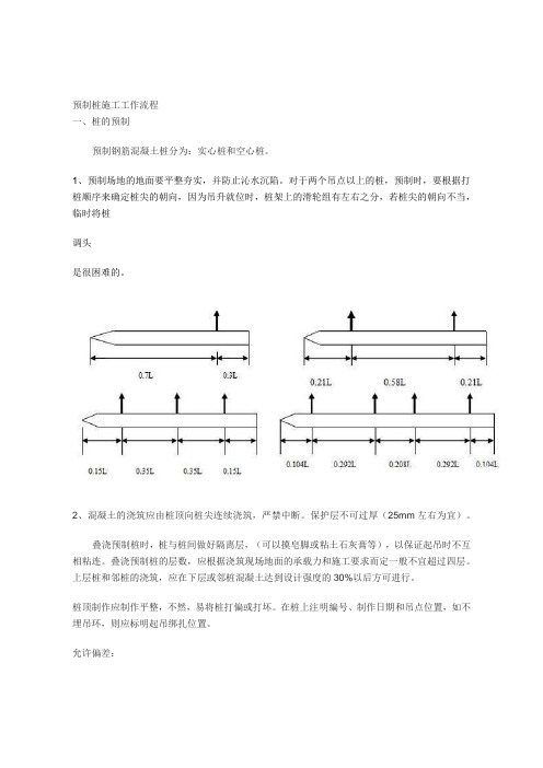
无规定时,可按以下规定:用一个吊点吊桩时,吊点设于距桩上端0.3倍桩长处;用两个吊点时,吊点设于距两端各0.21倍桩长处;用三个吊点时,吊点设置、在桩长中点及距离两端各0.15倍桩长处。
吊点的位置偏差不应超过设计位置20mm,吊点位置见上图。
使用起重机起吊时,应使桩纵轴线夹角小于450。
三、运输和堆放一般按打桩顺序随打随运,减少二次搬运。
地基处理与桩基施工(四)-锤击沉桩施工

(二)、锤击沉桩施工锤击沉桩也称打入桩,是靠打桩机的桩锤下落到桩顶产生的冲击能而将桩沉入土中的一种沉桩方法,该法施工速度快,机械化程度高,适用范围广,是预制钢筋混凝土桩最常用的沉桩方法。
但施工时有噪音和振动,对施工场所、施工时间有所限制。
1.打桩机具打桩用的机具主要包括桩锤、桩架及动力装置三部分。
1) 桩锤桩锤是打桩的主要机具,其作用是对桩施加冲击力,将桩打入土中。
主要有落锤、单动汽锤和双动汽锤、柴油锤、液压锤。
落锤一般由生铁铸成,重0.5~1.5t,构造简单,使用方便,提升高度可随意调整,一般用卷扬机拉升施打。
但打桩速度慢(6~20 次/min),效率低,适于在黏土和含砾石较多的土中打桩。
汽锤是利用蒸汽或压缩空气的压力将桩锤上举,然后下落冲击桩顶沉桩,根据其工作情况又可分为单动式汽锤与双动式汽锤。
单动式汽锤的冲击体在上升时耗用动力,下降靠自重,打桩速度较落锤快(60~80 次/min),锤重1.5~15t,适于各类桩在各类土层中施工。
双动式汽锤的冲击体升降均耗用动力,冲击力更大、频率更快(100~120 次/min),锤重0.6~6t,还可用于打钢板桩、水下桩、斜桩和拔桩。
柴油锤,柴油锤本身附有桩架、动力设备,易搬运转移,不需外部能源,应用较为广泛。
但施工中有噪声、污染和振动等影响,在城市施工受到一定的限制。
液压锤是一种新型打桩设备,它的冲击缸体通过液压油提升与降落,每一击能获得更大的贯入度。
液压锤不排出任何废气,无噪音,冲击频率高,并适合水下打桩,是理想的冲击式打桩设备,但构造复杂,造价高。
2) 桩架桩架是吊桩就位,悬吊桩锤,要求其具有较好的稳定性、机动性和灵活性,保证锤击落点准确,并可调整垂直度。
常用桩架基本有两种形式,一种是沿轨道行走移动的多功能桩架,另一种是装在履带式底盘上自由行走的桩架。
1—立柱;2—斜撑;3—回转平台;1—桩;2—斜撑;3—桩帽;4—桩锤;4—卷扬机;5—司机室;6—平衡重5—履带式起重机;6—立柱3) 动力装置打桩机构的动力装置及辅助设备主要根据选定的桩锤种类而定。
2016年二建《市政公用工程实务》考点辅导(29)
2016年⼆建《市政公⽤⼯程实务》考点辅导(29) 你了解⼆级建造师考试市政⼯程实务的沉⼊桩施⼯技术要求吗?沉⼊桩的常⽤的施⼯⽅法主要有:锤击沉桩、静⼒压桩。
跟着店铺⼆级建造师频道⼀起来了解⼀下吧,更多⼆级建造师市政⼯程实务考点请关注店铺⼆级建造师频道。
2016年⼆级建造师《市政⼯程实务》考点:沉⼊桩施⼯技术要求 沉⼊桩施⼯技术要求 沉⼊桩的常⽤的施⼯⽅法主要有:锤击沉桩、静⼒压桩。
⼀、锤击沉桩法 (⼀)锤击沉桩的特点 1、桩周围的⼟被挤密 2、在⼈⼝稠密的地⽅⼀般不宜采⽤。
(⼆)锤击沉桩设备选择 沉桩设备选择的⼀般思路为,选择锤型-----选择锤重-----选择桩架。
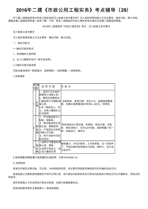
1.选择锤型序号锤型适⽤范围优缺点1坠锤1、适⽤于沉⽊桩和断⾯较⼩混凝⼟桩;2、重型及特重型龙门锤适⽤于沉钢筋混凝⼟桩;3.在⼀般粘性⼟、砂⼟、含有少量砾⽯⼟均可使⽤设备简单,使⽤⽅便,冲击⼒⼤,能随意调整落距,但锤击速度慢(每分钟约6—20次),效率低2柴油锤 1、杆式锤适宜沉⼩型桩、钢板桩;2、筒式锤适宜沉混凝⼟桩、钢管桩等;3、不适宜在过软或过硬⼟中沉桩;4、⽤于浮船中沉桩较为有利附有桩架动⼒等设备,机架轻,移动⽅便、沉桩快.燃料消耗少,也可以打钧桩,是使⽤最⼴的⼀种.但振动⼤,噪声⼤3液压锤 1.适⽤于沉重型的混凝⼟桩、钢桩;2.适⽤于粘性⼟,砂⼟含少量砾⽯等锤质量⼤,冲击次数多,⼯作效率⾼,在⼀定条件下,可保证锤对桩的锤击⼒控制,噪声⼩,且不会污染空⽓ 2.选择锤重(按锤质量与桩质量的⽐值选择,见表1K412021-2) 3. 选择桩架 桩架为沉桩的主要设备,可以⽤、⽊结构组拼⽽成,其主要作⽤是装吊锤和桩并控击锤的运动⽅向。
桩架因施⼯对象和使⽤锤型的不同可分两⼤类:⾃⾏移动式桩架和⾮⾃⾏移动式桩架⾃⾏移动式可分为履带式、导轨式和轮胎式。
城市桥梁施⼯⼤多采⽤⾃⾏移动式桩架,且都与桩锤配套供应。
桩架选择要考虑的主要因素之⼀是桩架⾼度。
锤击桩贯入度确定及施工质量控制

表1 桩基设计参数 层号 土层名称
预应力混凝土管桩(特征值)
qpk(kPa)
qsik(kPa)
②
粉质粘土
43
③
粉土
30
④
细砂
30
⑤ 全风化泥岩
3000
55
⑥ 强风化泥岩
7000
90
⑦ 中风化泥岩 根据设计要求,本工程选用第⑥层为桩基持力层。
施工工序安排
本工程选用导杆式柴油锤,锤重63kN,根据四平当地的施 工经验,第④层砂质致密,需先用长螺旋钻机引孔至第⑥层, 再进行锤击沉桩。下面简述实施流程:
根据四平地区管桩施工积累的经验数据,第⑥层回弹 量多在1~1.5cm之间,按保守的原则取K=1.5cm时,解得 s=2.05cm,计算结果与03SG409图集中数值基本吻合。
静载试验的验证
按照上述贯入度施工完试桩后进行静载试验,当堆载加 载到3460.6kN时,沉降量均在规范之内,满足设计要求。
施工质量控制要点
工程概况
1、设计概况 四平东站位于吉林省四平市铁东经济开发区,站房建筑 面积为5258.94平方米,平面尺寸大致为140.4×47.9m(屋 面投影),地上两层(设备及办公用房),局部一层(候车 大厅),层高5.3m,建筑总高18.9m。主站房采用全现浇框 架结构,基础为高强预应力管桩基础。桩型采用PHC-AB500 (100)-8a,单桩承载力为1537kN,极限承载力为3381kN。 2、工程地质简述 四平市位于松辽凹陷的东部边缘,是中朝地台的一部分, 四平市的地貌形态属于波状台地和一级阶地。白垩纪泥岩和砂 岩构成基底,台地的覆盖层为10~30m左右厚的粘性土层,底 部为厚度不等的砂层。车站底层构造情况如下: 第①层素填土 :黑、褐色,主要成分为粘性土,层厚 0.40~2.50 m。 第②层粉质粘土:褐黄色,稍湿,硬塑。层厚 0.30~4.90m。 第③层粉土:褐黄色,局部为褐灰色,含粗砂、砾砂及岩 石碎片,层厚0.30~2.40m。 第④层细砂:褐黄色~灰白色,层厚0.50~3.30m。
钢筋混凝土预制桩基础施工锤击沉桩法
▪桩架支持桩身和桩锤,保证锤击过程中的稳定性并保证桩锤按照要求
方向冲击的设备。
▪动力装置主要根据所选桩锤确定。
预制桩基础
施工工艺及质量控制
▪3、吊桩 ▪按照确定打桩顺序移动桩架至桩位处。 ▪先栓好吊桩的钢丝绳和锁具,然后应用锁具捆住桩上端吊环附近处一
般不宜超过30cm,再启动机器起吊预制桩,使桩尖对准桩位中心,缓缓 放下插入土中,位置要准确,再在桩顶扣好桩帽,即可出去锁具。
预制桩基础
施工工艺及质量控制
▪6、停锤 ▪停锤标准(沈桩的质量控制) ▪(1)摩擦桩位于一般土层时,一般控制桩端设计标高为主,贯入度
可做参考。(2)端承桩的入土深度以最后贯入度控制为主,桩端标高 做参考。(3)当贯入度已达到,而桩顶标高没有达到时,应继续锤击 三阵,按每阵10击的贯入度不大于设计规定的数量加以确定。
预制桩基础
-锤击沉桩法
预制桩基础
概述
桩基础是深基础应用最多的一种基 础形式,它由若干个沉入土中的桩 和连接桩顶的承台或承台梁组成。 桩的作用是将上部建筑物的荷载高地基土 的承载能力和密实度。
施工准备
预制桩基础
概述
▪ 桩按施工方法分为预制桩和灌注桩
▪质量控制标准:在打桩施工区域附近设置水准点,不少于2个,轴线
控制桩应设置在距最外桩5-10m处,以控制桩基轴线和标高。测量好 的桩位用钢钎打孔深度不大于200mm,用白灰灌入孔内,并在其上插入 钢筋棍。桩位放样允许偏差:群桩20mm,单桩10mm。
预制桩基础
施工工艺及质量控制
▪2、桩机就位 ▪根据图纸与现场要求(试桩)租赁打桩机械(桩锤、桩架、动力装置) ▪桩锤选择主要根据现场情况以及极具设备条件确定,锤重按照做功和
锤击沉入桩施工标准工艺
锤击沉入桩施工标准工艺锤击沉桩是一种将桩通过锤击打入地下土层的沉桩方法,能够将上部结构的荷载传递到更坚硬的土层或基岩上。
该工艺适用于松散、中密砂土、软塑和可塑的粘性土,并适用于钢筋混凝土桩、预应力混凝土管桩、钢管桩和木桩等类型的桩。
本文介绍了锤击沉桩的工艺概述、作业内容、质量标准及检验方法、工艺流程图以及工艺步骤及质量控制。
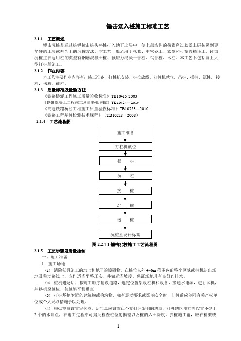
工艺流程包括施工准备、打桩机就位、插桩、沉桩、接桩、送桩、截桩等步骤。
在施工准备阶段,需要清除妨碍施工的地上和地下的障碍物,选定位置架设桩机和设备,并进行试机,移机至桩位,使桩架平稳垂直。
同时,需要根据测量设置定位点和水准点,以观测、控制桩的入土深度。
在技术准备阶段,需要取得工程地质资料、桩基施工相关图纸,并进行打桩工艺试验,检验打桩设备、打桩方案是否可行。
质量标准及检验方法包括《铁路桥涵工程施工质量验收标准》、《铁路混凝土工程施工质量验收标准》、《高速铁路桥涵工程施工质量验收标准》和《铁路工程基桩检测技术规程》。
工艺步骤及质量控制包括施工准备和技术准备两个方面。
在施工准备方面,需要清除妨碍施工的障碍物,选定位置架设设备,设置定位点和水准点等。
在技术准备方面,需要进行打桩工艺试验,检验设备和方案是否可行,并召开内部技术质量要求交底会,使每个施工参与人员牢记工程施工的质量要求和各工序的质量控制要点。
在沉桩时,应该使用“重锤轻击”的方法。
这种方法可以延长锤击时间,降低冲击应力,避免损坏桩头。
相比轻锤,使用重锤的冲击效率更高。
在沉桩过程中,需要随时注意桩的位移或倾斜情况。
如果有不正常的情况,需要及时纠正。
每根桩在沉桩时,都需要及时填写沉桩记录和沉桩记录整理表。
同时,需要按照每一墩、台桩基绘制桩位示意图。
停锤有以下几种情况:1.当桩尖设计位于硬塑及半干硬状态的黏性土、碎石土、中密状态以上的砂类土或风化岩层时,需要按照贯入度变化和工程地质资料,与有关单位会商,确认桩尖已沉入设计土层,贯入度符合要求时即可停锤。
锤击沉入桩施工工艺标准
锤击沉入桩施工工艺标准1. 工艺概述锤击沉桩是通过桩锤撞击桩头将桩打入地下土层中,使上部结构的荷载穿过软弱土层传递到更坚硬的土层或基岩上的沉桩方法。
本工艺一般适用于松散、中密砂土、软塑和可塑的粘性土。
锤击沉桩主要适用桩的类型有钢筋混凝土桩、预应力混凝土管桩、钢管桩、木桩。
2. 适用范围施工区域的土层宜以淤泥质粘土、粘土、粉土和N<30的土层为主,对于以N>30的土层或碎石土为主的土层,则会给沉桩带来一定的困难。
对于所选用的桩,有钢筋混凝土预制桩、钢管桩及钢筋混凝土预应力管桩等,宜根据土层的好坏、不同的桩尖持力层及单桩承载力要求分别选用。
3. 作业内容本工艺主要作业内容有:施工准备,打桩机安装,桩位放线,打桩机就位,吊桩、插桩、沉桩,接桩,送桩、截桩。
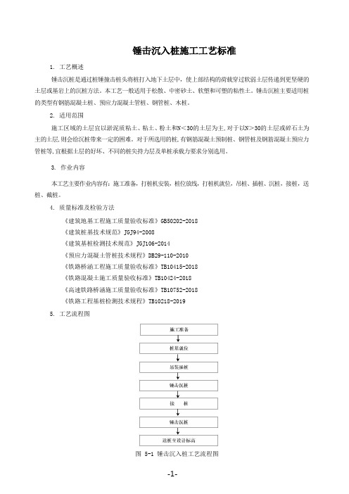
4. 质量标准及检验方法《建筑地基工程施工质量验收标准》GB50202-2018《建筑桩基技术规范》JGJ94-2008《建筑基桩检测技术规范》JGJ106-2014《预应力混凝土管桩技术规程》DB29-110-2010《铁路桥涵工程施工质量验收标准》TB10415-2018《铁路混凝土施工质量验收标准》TB10424-2018《高速铁路桥涵施工质量验收标准》TB10752-2018《铁路工程基桩检测技术规程》TB10218-20195. 工艺流程图图 5-1 锤击沉入桩工艺流程图6.工艺步骤及质量控制6.1 施工准备6.1.1 施工场地1)清除妨碍施工的地上和地下的障碍物。
在桩位以外 4~6m 范围内的整个区域或桩机进出场地及移动路线上,应作适当平整压实,并做适当坡度,保证场地具有良好的排水。
2)桩机进场后,按施工顺序铺设道路,选定位置架设桩机和设备,接通水电源,进行试机,并移机至桩位,使桩架平稳垂直。
3)打桩场地附近的建筑物或构筑物,如有震动要求或影响安全时,打桩前应会同有关产权单位或个人采取措施予以处理。
4)根据测量设置定位点,定位点应设置在不受打桩影响的地点,打桩地区附近需设置不少于2个的水准点,在施工过程中可据此检查桩位的偏差以及桩的入土深度。
锤击沉入桩施工标准工艺
锤击沉入桩施工标准工艺2.1.1工艺概述锤击沉桩是通过桩锤撞击桩头将桩打入地下土层中,使上部结构的荷载穿过软弱土层传递到更坚硬的土层或基岩上的沉桩方法。
本工艺一般适用于松散、中密砂土、软塑和可塑的粘性土。
锤击沉桩主要适用桩的类型有钢筋混凝土桩、预应力混凝土管桩、钢管桩、木桩。
本工艺不包括海上大型打桩船施工。
2.1.2作业内容本工艺主要作业内容有:施工准备,打桩机安装,桩位放线,打桩机就位,吊桩、插桩、沉桩,接桩,送桩、截桩。
2.1.3质量标准及检验方法《铁路桥涵工程施工质量验收标准》TB10415-2003《铁路混凝土工程施工质量验收标准》TB10424-2010《高速铁路桥涵工程施工质量验收标准》TB10753—2010《铁路工程基桩检测技术规程》(TB10218-2008)2.1.4工艺流程图图 2.2.4-1 锤击沉桩施工工艺流程图2.1.5工艺步骤及质量控制一、施工准备1.施工场地(1)清除妨碍施工的地上和地下的障碍物。
在桩位以外 4~6m 范围内的整个区域或桩机进出场地及移动路线上,应作适当平整压实,并做适当坡度,保证场地具有良好的排水。
(2)桩机进场后,按施工顺序铺设道路,选定位置架设桩机和设备,接通水电源,进行试机,并移机至桩位,使桩架平稳垂直。
(3)打桩场地附近的建筑物或构筑物,如有震动要求或影响安全时,打桩前应会同有关产权单位或个人采取措施予以处理。
(4)根据测量设置定位点,定位点应设置在不受打桩影响的地点,打桩地区附近需设置不少于桩侧面设置标尺,以观测、控制桩的入土深度。
2.技术准备(1)应取得工程地质资料、桩基施工相关图纸。
(2)桩基的轴线和高程均应测设完毕,并经过检查,办理复核手续。
(3)正式沉桩前应作数量不少于2 根桩的打桩工艺试验,用以了解桩的贯入度、持力层强度、桩的承载力,以及施工过程中遇到的各种问题和反常情况等。
并检验打桩设备、打桩方案是否可行,以保证桩的施工质量。
二级建造师市政工程重点知识归纳13
2K312020 城市桥梁工程基础施工技术
2K312021 掌握沉入桩施工技术要求
沉入桩基础常用的施工方法:锤击沉桩和静力压桩
一、锤击沉桩法
(一)锤击沉桩法的特点
(二)锤击沉桩设备选择
沉桩设备选择的一般思路:选择锤型—选择锤重—选择桩架
(三)沉入桩的施工技术要求
1、水泥混凝土桩要达到100%设计强度并具有28d龄期
2、重锤低击。
3、打桩顺序:一端——另一端、先中心后周围、先深桩后浅桩、先坡顶后坡脚
4、在桩的打入过程中,应始终保持锤、桩帽和桩身在同一直线上
5、沉桩时,以控制桩尖设计标高为主
6、无论桩多长,打桩和接桩均须连续作业,中间不应有较长时间的间歇
7、在一个墩、台桩基中,同一水平面内的桩接头数不得超过桩基数的1/4
8、沉桩过程中,如遇贯入度剧变,桩身突然发生倾斜、位移或有严重回弹,桩顶或桩身出现严重裂缝、破碎等应暂停沉桩。
二、静力压桩法
2011年二级建造师考试,。
所有基础桩打完的标准
所有基础桩打完的标准基础桩打完的标准包括以下几个方面:1. 质量要求:成品桩外观无蜂窝、露筋、裂缝、色感均匀、桩顶处无孔隙。
严禁使用质量不合格及在吊运过程中产生裂缝的桩。
在吊运过程中应轻吊轻放,避免剧烈碰撞。
2. 锤击沉桩:锤桩顺序对于密集桩群,自中间向两个方向或四周对称施打;当一侧毗邻建筑物时,由毗邻建筑物处向另一方向施打;根据基础的设计标高,宜先深后浅;根据桩的规格,宜先大后小,先长后短。
桩帽或送桩帽与桩周围的间隙应为5~10mm;锤与桩帽、桩帽与桩之间应加设硬木、麻袋、草垫等弹性衬垫;桩锤、桩帽或送桩帽应和桩身在同一中心线上;桩插入时的垂直度偏差不得超过%。
斜桩倾斜度的偏差不得大于倾斜角正切值的15%(倾斜角系桩的纵向中心线与铅垂线间夹角)。
3. 焊接接桩:钢钣宜采用低碳钢,焊条宜采用E43,产品合格证检查。
焊接时,下节桩段的桩头宜高出地面;下节桩的桩头处宜设导向箍。
接桩时上下节桩段应保持顺直,错位偏差不宜大于2mm;接桩就位纠偏时,不得采用大锤横向敲打。
桩对接前,上下端板表面应采用铁刷子清刷干净,坡口处应刷至露出金属光泽。
焊接宜在桩四周对称地进行,待上下桩节固定后拆除导向箍再分层施焊;焊接层数不得少于2层,第一层焊完后必须把焊渣清理干净,方可进行第二层(的)施焊,焊缝应连续、饱满。
焊好后的桩接头应自然冷却后方可继续锤击,自然冷却时间不宜少于8min;严禁采用水冷却或焊好即施打。
雨天焊接时,应采取可靠的防雨措施;焊接接头的质量检查,对于同一工程探伤抽样检验不得少于3个接头。
4. 送桩:送桩深度不宜大于;当桩顶打至接近地面需要送桩时,应测出桩的垂直度并检查桩顶质量,合格后应及时送桩;送桩的最后贯入度应参考相同条件下不送桩时的最后贯入度并修正;送桩后遗留的桩孔应立即回填或覆盖。
5. 终止:当桩端位于一般土层时,应以控制桩端设计标高为主,贯入度为辅;当桩端达到坚硬、硬塑的黏性土、中密以上粉土、砂土、碎石类土及风化岩时,应以贯入度控制为主,桩端标高为辅。
地基处理与桩基施工(四)-锤击沉桩施工

(二X锤击沉桩据工锤击沉桩也称打入桩,是靠打桩机的桩锤下落到桩顶产生的冲击能而将桩沉入土中的一种沉桩方法,该法施工速度快,机械化程度高,适用范围广,是预制钢筋混擬土桩最常用的沉桩方法。
但施工时有噪音和振动,对施工场所、施工时间有所限制。
打桩用的机具主要包括桩锤、桩架及动力装置三部分。
1)桩锤桩锤是打桩的主要机具,其作用是对桩施加冲击力,将桩打入土中。
主要有落锤、单动汽锤和双动汽锤、柴油锤、液压锤。
落锤一般由生铁铸成,重0.5~1.5t ,构造简单,使用方便,提升高效率低,适于在黏土和含砾石较多的土中打桩。
汽锤是利用蒸汽或压缩空气的压力将桩锤上举,然后下落冲击桩顶沉桩,根据其工作情况又可分为单动式汽锤与双动式汽锤。
单动式汽锤的冲击体在上升时耗用动力,下降靠自重,打桩速度较落锤快(60-80次/min),锤重1.5-15t ,适于各类桩在各类土层中施工。
双动式汽锤的冲击体升降均耗用动力,冲击力更大、频率更快(100-120次/min),锤重0.6~6t ,还可用于打钢板桩、水下桩、斜桩和拔桩。
柴油锤,柴油锤本身附有桩架、动力设备,易搬运转移,不需外部能源,应用较为广泛。
但施工中有噪声、污染和振动等影响,在城市施工受到一定的限制。
液压锤是一种新型打桩设备,它的冲击缸体通过液压油提升与降落, 每一击能获得更大的贯入度。
液压锤不排出任何废气,无噪音,冲击频率高,并适合水下打桩,是理想的冲击式打桩设备,但构造复杂,造价2)桩架桩架是吊桩就位,悬吊桩锤,要求其具有较好的稳定性、机动性和灵活性,保证锤击落点准确,并可调整垂直常用桩架基本有两种形式,一种是沿轨道行走移动的多功能桩架,另一种是装在履带式底盘上自由行走的桩架。
1 一立柱;2—斜撑;3—回转平台; 1 一桩;2—斜撑;3亠桩帽;4—桩锤;4—卷扬机;5—司机室;6-平衡重 5 一履带式起重机;6—立柱3)动力装置打桩机构的动力装置及辅助设备主要根据选定的桩锤种类而定。
锤击沉桩技术要点
锤击沉桩技术要点第一小节锤击桩主要施工技术措施[ 1 ]打桩前的施工准备1、在打桩现场或附近需设置水准点,数量为两个以上,用以抄平场地和检查桩的入土深度。
根据建筑物的轴线控制桩定出桩基每个桩位,作出标志,并在打桩前,请总包、监理对桩的轴线和桩位进行复验。
2、打桩机进场后,应按施工顺序铺设轨垫(钢板),安装桩机和设备,接通电源、水源,并进行试机。
然后移机至起点桩就位,桩架应垂直平稳。
[ 2 ]沉桩施工要点:1、由吊车先两点起吊、后单点起吊,单点吊吊点位置,用钢丝绳绑在桩上部约0.295L(L为桩长)处。
桩帽与桩接触的表面应平整,与桩身应在同一直线上。
2、当桩吊起就位后,要缓缓放下,插入土中,进行桩位和垂直度校正后,并在桩身侧面或桩架上设置标尺,做好记录,才能开始施打,开始时应起锤轻压或轻击数锤,待锤以及桩身等垂直度一致后,即可转入正常施打。
3、为了避免打桩过程中桩顶部的损坏,可在桩顶放上弹性垫层,如草纸﹑麻袋或草绳等,放下桩帽套入桩顶时,将桩帽放上垫木。
桩锤底面﹑桩帽上下面和桩顶应保持水平。
桩锤﹑桩帽和桩身中心线应在同一线上。
4、打桩应“重锤低击”﹑“低提重打”。
桩开始打入时,桩锤落距宜小。
一般为1.5~0.8米,打入一定深度后方可增加落距,最大不超过1.8米。
[ 3 ]桩停止锤击的控制原则:1、桩端位于一般土层时,以控制桩端设计标高为主,贯入度可作参考;2、桩端到坚硬、硬塑的粘性土、粉土、中密以上砂土时,以贯入度控制为主,桩端标高作参考;3、贯入度已达到而桩端标高未达到时,应继续锤击3阵,按每阵10击的贯入度不大于设计规定的数值加以确认,必要时贯入度应通过试验或与有关单位确定。
[ 4 ]方桩焊接桩的连接采用角钢帮焊连接。
端头钢板与桩的轴线垂直,钢板平整,以使相连接的二桩节轴线重合,连接后桩身保持竖直。
接头施工时,当下节柱沉至桩顶离地面0.8~1.5m处便吊上节桩。
若二端头钢板之间有缝隙,用薄钢片垫实焊牢,然后由两人进行对称对角分段焊接沿接桩处共焊接三遍。
市政工程锤击打桩沉桩施工安全操作要点
市政工程锤击打桩沉桩施工安全操作要点1、锤击沉桩工艺要点(1)桩机就位并调整,使桩架(或导杆)处于铅垂状态,并在拟打桩的侧面或桩架上设置标尺。
(2)根据桩长,采用合适的吊点将桩起吊,并令其垂直对准桩位中心,将桩锤下的桩帽(已加好缓冲垫材)徐徐松下套在桩顶,解除吊钩,检查并使桩锤、桩帽与预制桩三者处于同一纵轴线上,且垂直插入土中。
(3)起锤轻压或锤击,在两台经纬仪的校正下,使插桩保持垂直,无异常即可正式打桩。
(4)在开始锤击时,落距应较小,当入土一定深度并待桩稳定后,再按要求落距沉桩,采用柴油锤时,应保持锤跳动正常。
沉桩过程中,注意桩身是否发生位移或倾斜,若有不正常,应及时纠正,并同时做好沉桩记录。
(5)当有接桩要求时,应按设计要求及有关施工操作规程进行。
(6)当有送桩要求时,对桩顶平面位置进行中间验收。
送桩时,要选用合适的送桩工具,并使送桩工具中心线与桩身中心线吻合一致,送桩结束,即拔出送桩工具,并应及时将桩孔填盖。
2、锤击沉桩的安全技术措施(1)摸清环境情况,建立监测、监控组织。
开工前总承包和分包施工单位必须对基地附近的建(构)筑物和地下各种管线调查清楚,并绘制相应的平、剖面图,并配合建设单位与各种管线的主管单位取得联系,核对管线情况,成立工地施工现场监护小组,确立锤击沉桩监测方案和防护方案。
(2)设置排水系统:打桩时挤土也挤水。
一般排水有两种做法:一种是在打桩之前向基地内打入塑料排水板;另一种是向基坑内打入袋装砂井。
这些塑料排水板或袋装砂井上都要有相通的排水沟,并保证通过这些排水沟将排放出地面的孔隙水排到基地外。
(3)设置防振沟:打桩对环境的破坏作用除了挤压还有振动。
具体做法有:打二排钢板桩,中间土体挖空一定深度;打一排钢机桩,挖沟填砂;不打钢板桩,只挖沟填砂;只挖沟,不填砂等。
防振沟还可减少局部土体的挤动。
(4)控制打桩速度:打桩速度对土体的影响极大,因为软土地基的土壤内含有大量的孔隙水,如果一根桩打入后,隔一段时间孔隙水压消失一点,再打入一根桩,这样慢慢打入可减少孔隙水压的提高,使土体的挤动减小。
锤击桩打桩顺序及控制要点 Microsoft Word 文档

锤击桩打桩顺序及控制要点(1)桩材起吊起重工指挥桩机起吊桩体,使桩头进入桩帽,桩起吊采用一点吊,吊点位置离开桩头2米左右。
(2)喂桩桩尖对正桩位中心,并使桩体基本垂直。
桩插入就位桩尖对正桩位中心,并使桩体垂直,用两台经纬仪成90°同时找正,使桩锤、桩帽、桩中心线在同一垂直线上。
(3)锤击沉桩先用冷锤轻击桩体,桩入土1~2米(不能超过3m)后再调整桩垂直度,校核垂直度时,先校正导杆,后校正桩,确认桩的中心位置及垂直度不超过0.5%后,再正式施打,同时作好打桩记录及垂直度观测记录,当桩顶打到距地面60~80cm时停锤,准备接桩。
打桩时桩帽与桩周围的间隙应在5-10mm之间。
施工用焊丝应具备产品出厂合格证及材料部门提供的复验报告。
打桩过程中要结合地质勘察报告进行,在桩进入淤泥层时应特别注意控制桩的垂直度。
沉桩过程中如发生异常情况应及时与现场监理及有关单位研究确定处理。
(4)接桩焊接起吊上节与下节桩相接(接桩时用2米靠尺检查桩的顺直度),焊接前均应除锈、挡风,焊缝连续饱满,符合设计要求和施工规范的规定。
为提高效率,采用我公司已经成熟的二氧化碳半自动气体保护焊工艺接桩,既能保证焊接高质量,又能提高焊接速度。
但采用此工艺施焊时对焊工素质、焊接工艺、气体质量、现场环境的要求都相当高。
为此,必须做到:a.焊接前将桩头处的水泥、水、锈、油脂、灰等彻底清除干净。
用砂轮机反复打磨桩头平面及周边,直至金属表面出现光泽为止。
b.焊接时每个接头由两名焊工在两侧同时对称施焊。
焊接采用三层横向焊接工艺,焊接工艺的要点是准确掌握好电流、电压、送丝速度及施焊角度。
CO2气体要保证纯度,含水量不超标。
c.焊工必须是经过严格培训,经考试合格并取得操作合格证,长期从事二氧化碳气体保护焊施工,保证多、快、好、省地完成焊接施工任务。
d.接桩施焊时需配置专用防风罩对焊接区进行遮挡,保证焊接在无风状态下进行,以确保焊接质量。
e.上、下桩节的中心线偏差不得大于2mm。
2017一级建造师建筑工程考点:桩基础施工技术2017一级建造师
2017一级建造师建筑工程考点:桩基础施工技术2017一级建造师复习2017年一建建筑工程的考生们,一定不要错过本文“2017一级建造师建筑工程考点:桩基础施工技术”由一级建造师考试网整理而出的重点哦,祝您顺利通过一级建造师考试!1A413030建筑工程地基处理与基础工程施工技术1A413032 桩基础施工技术1.预制桩按沉桩方法分:锤击沉桩、静力压桩、振动法。
2. 锤击施工程序:确定桩位和沉桩顺序一桩机就位一吊桩喂桩一校正一锤击沉桩一接桩一再锤击沉桩一送桩一收锤一切割桩头31.打桩顺序:从中间向(两端对称)四周;先长后短、先大后小、先深后浅32.打桩宜“重锤低击”、“低锤重打”桩身的垂直度偏差不得大于0.5%。
33.常用的接桩方式主要有焊接法、法兰螺栓连接法和硫黄胶泥锚接法。
34.桩的入土深度,对于承受轴向荷载的摩擦桩,以标高为主,贯入度作为参考;对于端承桩则以贯入度为主,标高作为参考。
4.压桩过程中应检查压力、桩垂直度、接桩间歇时间、桩的连接质量及压入深度50.灌注桩按其成孔方法分:钻孔、沉管、人工挖孔51.钻孔灌注桩有冲击钻成孔灌注桩、回转钻成孔灌注桩、潜水电钻成孔灌注桩及钻孔压浆灌注桩等。
除钻孔压浆灌注桩外,其他三种均为泥浆护壁钻孔灌注桩52.锤击沉管灌注桩:适于黏性土、淤泥、淤泥质土、稍密的砂石及杂填土层中使用;但不能在密实的中粗砂、砂砾石、漂石层中使用53.振动沉管灌注桩根据承载力的不同要求,拔管方法分单打法、复打法、反插法61.进行强度检验时,对承重(支护)水泥土搅拌桩取90(28)天后的试件;62.灌注桩的桩顶标高至少要比设计标高高出0.5m P41763.对特殊灌注桩的承载力检验,应采用静载荷试验的方法进行检验,检验桩数不应少于总数的1%,且不应少于3根,当总数少于50根,不应少于2根。
P41764.重要工程应对电焊接桩的接头做10%的探伤检查65.桩位的放样允许偏差如下:P416(1)群桩20mm;(2)单排桩10mm。
预制桩施工的注意事项

预制桩施工的注意事项混凝土预制桩能承受较大的荷载、坚固耐久、施工速度快,是广泛应用的桩型之一,但其施工对周围环境影响较大,常用的有混凝土实心方桩和预应力混凝土空心管桩。
钢桩主要是钢管桩和h型钢桩两种。
以下是预制桩施工的注意事项,欢迎阅读。
下面为你介绍混凝土预制桩的打桩方法:1.打桩机就位后,将桩锤和桩帽吊起,然后吊桩并送至导杆内,垂直对准桩位缓缓送下插入土中,垂直偏差不得超过0.5%,然后固定桩帽和桩锤,使桩、桩帽、桩锤在同一铅垂线上,确保桩能垂直下沉。
在桩锤和桩帽之间应加弹性衬垫,桩帽和桩顶周围四边应有5~10mm 的间隙,以防损伤桩顶。
锤击法打桩过程打桩开始时,应先采用小的落距(0.5~0.8m)作轻的锤击,使桩正常沉入土中约1~2m后,经检查桩尖不发生偏移,再逐渐增大落距至规定高度,继续锤击,直至把桩打到设计要求的深度。
最大落距不宜大于1m,用柴油锤时,应使锤跳动正常。
在打桩过程中,遇有贯入度剧变、桩身突然发生倾斜、移位或有严重回弹、桩顶或桩身出现严重裂缝或破碎等异常情况时,应暂停打桩,及时研究处理。
2.打桩有“轻锤高击”和“重锤低击”两种方式。
这两种方式,如果所做的功相同,而所得到的效果却不相同。
轻锤高击,所得的动量小,而桩锤对桩头的冲击力大,因而回弹也大,桩头容易损坏大部分能量均消耗在桩锤的回弹上,故桩难以入土。
相反,重锤低击,所得的动量大,而桩锤对桩头的冲击力小,因而回弹也小,桩头不易被打碎,大部分能量都可以用来克服桩身与土壤的摩阻力和桩尖的阻力,故桩很快入土。
此外,又由于重锤低击的落距小,因而可提高锤击频率,打桩效率也高,正因为桩锤频率较高,对于较密实的土层,如砂土或粘性土也能较容易地穿过,所以打桩宜采用“重锤低击”。
试桩加荷方法(1)重物加荷法:在试桩的顶上架设钢制或木制加荷平台,上堆重物作为施加荷载,重物一般用条石、砖块、铸铁、钢锭等。
其加荷情况如图1(a)所示。
这种加荷设备简单,适应面广。
- 1、下载文档前请自行甄别文档内容的完整性,平台不提供额外的编辑、内容补充、找答案等附加服务。
- 2、"仅部分预览"的文档,不可在线预览部分如存在完整性等问题,可反馈申请退款(可完整预览的文档不适用该条件!)。
- 3、如文档侵犯您的权益,请联系客服反馈,我们会尽快为您处理(人工客服工作时间:9:00-18:30)。
1Hammer ’s Impact Force on Pile and Pile ’s PenetrationJi-Cheng WangInstitute of Architectural Engineering, Ningbo University of Technology, Ningbo, Zhejiang,China Jianlin YuCollege of Civil Engineering and Architecture, Zhejiang University, Hangzhou, ChinaMa ShiguoNingbo Urban Construction Investment Holding Company Limited, Ningbo, Zhejiang, ChinaXiaonan GongCollege of Civil Engineering and Architecture, Zhejiang University, Hangzhou, China Address correspondence to Ji-Cheng Wang, No. 201, Fenghua Road, Jiangbei District, Ningbo, Zhejiang 315211, China. E-mail: wjc1818@Color versions of one or more of the figures in the article can be found online at /wifa.AbstractMethods of energy and momentum conservation, vibration theories, and model tests are employed to research into impact force of hammer on pile and pile ’s penetration Analytical formula of impact force of hammer on pile is obtained. Comparison of results from the three methods finds that the analytical formula proposed by this paper conforms well to practical situations. Research resultsD o w n l o a d e d b y [J i c h e n g W A N G ] a t 21:22 29 M a y 2015Marine Georesources & Geotechnology To cite this article:Ji-Cheng Wang, Jianlin Yu, Shiguo Ma & Xiaonan Gong (2015): Hammer's Impact Force on Pile and Pile'sPenetration, Marine Georesources & Geotechnology, DOI: 10.1080/1064119X.2015.1016637To link to this article: /10.1080/1064119X.2015.1016637 Accepted author version posted online: 28 May 2015.2show that, If hammer ’s impact energy remains unchanged, Penetration increases with the increase of hammer weight and cushion stiffness; Impact force the pile head receives degrades with the increase of hammer weight but increases with the increase of cushion stiffness; Impact time decreases with the increase of cushion stiffness but increases with the increase of hammer weight. Model test shows that, compared with cotton cloth cushion, elastic cushion ’s advantages lie in that relatively small pile head impact force can achieve big pile penetration, and cotton cloth is gradually compacted with the increase of blow counts, hence impact force the pile head receives tends to increase gradually.KeywordsINTRODUCTIONHammer piling is simple and economical, and has a great penetrability, hence is widely used. However, hammer ’s impact force on pile is usually very big, thus causing damage to pile head. Besides, hammer weight selection is generally empirical. Hammer ’s impact force on pile is usually calculated through pile driving formula, which are deduced from laws of energy and momentum conservation together with empirical parameters as energy utilization efficiency, coefficient of restitution, etc., such as the widely used Hiley (1925) Formula. Smith ’s (1960) model used lumped mass as hammer, and used weightless spring as anvil cushion. Helmet and cap cushion were all regarded as part of the pile. Wave equation analysis was used to simulate dynamic response of pile driving (Smith 1960). Rausche, Goble, and Likins (1985) proposed a pile driving dynamic model which was more complex than Smith ’s (Rausche, Goble, and Likins 1985). Deeks and Randolph (1990, 1991, 1993) built a model comprising piling hammer, anvil cushion, and helmet which was directly attached to pile top and proposed analytical solutions to this modelD o w n l o a d e d b y [J i c h e n g W A N G ] a t 21:22 29 M a y 20153considering anvil cushion ’s elasticity and viscoelasticity (Randolph, Banerjee, and Buttefield 1991; Deeks and Randolph 1993, 1995). Koten (1991) researched into a simple hammering model comprising piling hammer and anvil cushion (Koten 1991). Take, Valsangkar, and Randolph (1999) analyzed interaction of piling hammer, anvil cushion, helmet, and cap cushion. The paper used lumped masses for the ram and anvil, a spring for the anvil cushion, and another spring for the cap cushion on the top of a pile. Pile and soil interaction was not considered. Take analyzed blow stress wave on pile top by using mass-spring-dashpot model and numerical computation method (Take, Valsangkar, and Randolph 1999). Runfu and Qing (2000) simplified pile to onedimensional rod and analyzed it by using stress wave solution and proposed a stress solution of pile (Runfu and Qing 2000). Based on one dimensional stress wave theory, Shifang et al. (2003) researched into impact force and penetration by building an interaction model of hammer, pile, and soil and obtained analytical solutions of pile end displacement and velocity (Shifang, Renpeng, and Yunmin 2004). Hehua, Yongjian, and Huaizhong (2004) used different lumped mass for piling hammer and helmet, and parallel spring and dashpot for anvil cushion, and spring for cap cushion, and dashpot for pile, and established an equilibrium equation, and then used the Laplace Transform to deduce analytical solutions of hammering force (Hehua, Yongjian, and Huaizhong 2004; Yongjian et al. 2005). Liyun and Pu'an (1994) carried out a simulation piling test of small diameter steel pipe pile and concluded that disc spring could improve piling efficiency (Liyun and Pu'an 1994). Renpeng et al.(2001) monitored pile body stress in piling and obtained relationships among blow count, pile length, and pile body ’s maximal stress (Renpeng et al. 2001). Peng-kong and Subrahmanyam (2003) researched into pile driving formula considering pile length factor by using one dimensional wave equation (Peng-kong and Subrahmanyam 2003). Based on Hiley Formula, So and Ng (2010) researched into impact compression behaviors of high-capacity long piles (SoD o w n l o a d e d b y [J i c h e n g W A N G ] a t 21:22 29 M a y 20154and Ng 2010). With examples, Middendorp and van Weel (1986) attested that under most conditions, simple models could provide force and velocity response curve which was accurate enough (Middendorp and van Weel 1986; Middendorp 2004). This article simplifies the systemm S viz. hammer and pile stick together to move downward after collision. Here H P v v v c . Upon receiving kinetic energy, pile overcomes soil ’s frictional resistance and sinks, then:D o w n l o a d e d b y [J i c h e n g W A N G ] a t 21:22 29 M a y 201552H P 1()2W m m v c (2)According to momentum conservation, we have:0H P ()H m v m m v c (3)H P(7)In which S Plastic is penetration when complete plastic impact occurs between pile and hammer. From Eq. (7) we have:D o w n l o a d e d b y [J i c h e n g W A N G ] a t 21:22 29 M a y 20156H0P PlasticHP1m E m S m f m(8)It can be seen from Eq. (8) that if hammer ’s kinetic energy 20H 012E m v remainsp Then energy utilization efficiency is:D o w n l o a d e d b y [J i c h e n g W A N G ] a t 21:22 29 M a y 20157H 2P PP 220HH 0P 142112m m v m W E m m v m K§· ¨¸©¹ (11)Relationship between energy utilization efficiency K and m H /m p is illustrated in Figure 2.s Relationship between penetration S Elastic and m H /m p is illustrated in Figure 2. It can be seen that just as energy utilization efficiency K , if hammer ’s initial kinetic energy remains unchanged, when m H <m p , penetration S Elastic increases significantly with the increase of m H . When m H =m p ,D o w n l o a d e d b y [J i c h e n g W A N G ] a t 21:22 29 M a y 20158penetration is the biggest, and 0Elastic E S f. When m H >m p , penetration S Elastic degrades gradually with the increase of m H . It can also be seen that when m H =3m p , penetration is 034E f, be it usingAssume elastic cushion stiffness coefficient is k H . Pile will not sink if anvil cushion ’s thrust for pile is smaller than soil ’s frictional resistance to pile f . This part of hammer ’s energy is transferred to cushion ’s compression energy, hence:D o w n l o a d e d b y [J i c h e n g W A N G ] a t 21:22 29 M a y 201592LossH 122f E fx k (17)In which x is compressed length of cushion under the effect of energy loss E Loss . Energy utilization efficiencyS s 2H 2H 0f k m v (22)Viz. when cushion stiffness 2H 2H 0f k m v , hammer ’s all kinetic energy is transferred to cushion ’s compression potential energy and will not cause pile to sink.D o w n l o a d e d b y [J i c h e n g W A N G ] a t 21:22 29 M a y 201510When Soil's Resistance to Pile Is Very BigWhen pile receives very big resistance during sinking process and penetration is very small and is negligible, foundation soil ’s stiffness can be seen as P k f , then the system comprising hammer,sinking. When hammer ’s velocity v H equals to pile ’s velocity v P (assume H P v v v c ), cushion is compressed to the thinnest, hence cushion receives the biggest pressure. ThenH 0H P ()m v m m v c (26)D o w n l o a d e d b y [J i c h e n g W A N G ] a t 21:22 29 M a y 201511We can obtain:H 0H P m v v m m c(27)The whole system ’s kinetic energyFrom Eqs. (25) and (32), we have:D o w n l o a d e d b y [J i c h e n g W A N G ] a t 21:22 29 M a y 201512max,P max,P 01k k F F f ! (33)It can be seen from Eq. (33) that max,P max,P 0k k F F f!, and the bigger m H /m p is, the bigger thedifference between max,P k F f and max,P 0k F will be.Actually, foundation soil ’s stiffness k P falls between 0 and f , and the maximal impact force F max the pile head receives satisfies the following Eq.:max,P 0max max,P k k F F F f(34)ANALYSES BASED ON VIBRATION THEORIESTheoretical Analysis of Impact Force Pile Head ReceivesLiteratures (Deeks and Randolph 1993; Take, Valsangkar, and Randolph 1999; So and Ng 2010) reveal that, compared with impact force, gravity of hammer and pile is very small and can be negligible. Compared with anvil cushion and foundation soil, hammer and pile have relatively great stiffness and can be approximately seen as rigid bodies. These literatures (Deeks and Randolph 1993; Take, Valsangkar, and Randolph 1999; So and Ng 2010) also show that hammer exerts the biggest impact force on pile at initial stage of hammering. At this stage, pile and its surrounding soil take relatively small sinking and no relative displacement occurs. Hence vertical downward sinking deformation is mainly elastic deformation. This is illustrated in Figures1(c) and 1(d). Then it can be assumed that soil ’s resistance and pile ’s sinkage display a direct ratio. Select the equilibrium position of hammer and pile as origin of coordinates, and select the displacements x H and x P of hammer and pile which deviate from the equilibrium position as coordinates, just as illustrated in Figure 4(c). When vibration occurs with the system, the forcesD o w n l o a d e d b y [J i c h e n g W A N G ] a t 21:22 29 M a y 201513the hammer and the pile receive are illustrated in Figure 4(d). Establish force equations of the system:P P P P H H P H H H H P ()()m x k x k x x m x x x ®¯k P P H H P x k x k (x Eqs. (36) is a second-order linear homogeneous differential equation set. To make it®¯x P P bx x P x H dx 22()0()0b A cB dA d B Z Z °® °¯ (41)D o w n l o a d e d b y [J i c h e n g W A N G ] a t 21:22 29 M a y 201514Eqs. (41) are a linear equation set of vibration amplitudes A and B . When vibration occurswith the system, the equation set has non-zero solutions, and determinant of coefficient of the equation set must be 0, viz.:b d §¨¸©¹2 1Z 22212b b d c c Z J ª° «°«°¬¯(46)Kinematic equations of vibration (first principal vibration) corresponding to first natural frequency 1Z is:D o w n l o a d e d b y [J i c h e n g W A N G ] a t 21:22 29 M a y 201515(1)P 111(1)H 111sin()sin()x A t x B t Z T Z T °® °¯ (47)Kinematic equations of vibration (second principal vibration) corresponding to second natural frequency 2Z is:(2)P 222(2)H 222sin()sin()x A t x B t Z T Z T °® °¯ (48)With theories of differential equations, general solution of free vibration differential Eq. (38) can be obtained from Eqs. (47) and (48):P 111222H 11112222sin()sin()sin()sin()x A t A t x A t A t Z T Z T J Z T J Z T ®¯ (49)Eqs. (49) include four undetermined constants A 1, A 2, T 1, and T 2.When t = 0, the distances of hammer and pile from equilibrium position are all 0, viz. x P = 0, x H = 0. Substitute them into Eqs. (49), we have:1122111222sin sin 0sin sin 0A A A A T T J T J T ®¯ (50)Take the derivative of Eq. (49) with t , we have:11222211122222cos()cos()cos()cos()t A t t A t Z Z T Z Z T Z J Z T Z J Z T ®¯11xP A c11x H A (51)When t = 0, hammer ’s velocity x v H 0, pile ’s velocity x 0P . Substitute them into Eqs. (51), we have:111222*********cos cos 0cos cos A A A A v Z T Z T Z J T Z J T ®¯ (52)From Eqs. (50) and (52), we can obtain:0012121122120,,()()v v A A T T Z J J Z J J(53)Substitute Eqs. (53) into Eqs. (49), we have motion equations of hammer and pile:D o w n l o a d e d b y [J i c h e n g W A N G ] a t 21:22 29 M a y 20151600P 121122121020H 12112212sin sin ()()sin sin ()()v v x t t v v x t t Z Z Z J J Z J J J J Z Z Z J J Z J J ° °®° ° ¯ (54)It can be noted that if soil ’s frictional resistance to pile is very small and is negligible, thenP k x 11Jx H J H H x m H H H § ¨©x m 1 and Z 2. Again, substitute it into Eqs. (46), we have J 1 and J 2. Substitute Z 1, Z 2, J 1, and J 2 into second equation of Eqs. (54), we have:D o w n l o a d e d b y [J i c h e n g W A N G ] a t 21:22 29 M a y 2015171020H 1201112212sin sin sin ()()v v x t t tJ J Z Z Z Z J J Z J J(58)Take the second derivative of Eq. (58), we have:H m kx H k mx H H k Hmax x n1t P P 02sin F tZ (63)The maximal value of Eq. (63) is:D o w n l o a d e d b y [J i c h e n g W A N G ] a t 21:22 29 M a y 201518max 0max,P 0k F F (64)The conclusion is the same as the conclusion drawn from Eq. (32). When 222t n SZ S(nis nonnegative integer), Eq. (64) is true. Hammer separates from pile after collision, hence 2t ZD o w n l o a d e d b y [J i c h e n g W A N G ] a t 21:22 29 M a y 201519Assume m P = 1.56 kg, k H = k P = 3.6×10⁵ N/m. Hammer ’s initial energy 08N mE remains unchanged, Change hammer weight and fall height. Hammer ’s impact force on pile can be calculated with Eq. (57), as illustrated in Figure 7.As mentioned above, negative impact force means hammer separates from cushion. It can be seen from Figure 7 that, for identical hammer impact energy, the bigger the hammer weight is, the smaller the hammer ’s impact force on pile will be, and the longer the impact time will last. When m H >m P (1.56 kg), viz. hammer weight is bigger than pile weight, hammer ’s impact force onpile remains bigger than 0.ANALYSES BASED ON MODEL TESTEquipment parts of the model test are shown in Figure 8(a), and assembly drawing is illustrated in Figure 8(b). Loose uniform sand, void ratio is 0.8㸪relative density D r = 45%㸪dry unit weight is 14.5 kN/m 3, pile ’s lower end just touches soil surface. Lift hammer to a certain height, and let it fall down freely and hit spring, then the pile will sink.Elastic Cushion TestHammer ’s initial energy is 08N m E , and m H = 1.04 kg, and m P = 1.56 kg, and spring stiffness k H = 3.6×10⁵ N/m. An accelerometer attached to hammer is used to measure hammer ’s acceleration when hitting spring. Hammer ’s actual impact force on spring is indirectly measured, as illustrated in Figure 9. Because soil ’s stiffness coefficient k P is unknown, here let k P = 0, 180, 360, 540, 720, 900, 1260, 1440, 2000, 4000 kN/m and infinitely great. Substitute these values into Eq. (57), hammer ’s impact force on pile can be achieved, as illustrated in Figure 9. It can be seen that measured impact force is approximate to theoretical value. Especially when k P = 360 kN/m,D o w n l o a d e d b y [J i c h e n g W A N G ] a t 21:22 29 M a y 201520the maximal impact force measured is nearly identical with theoretical value. From Eqs. (62) and (63), it can be calculated that the times when maximal impact forces occur is 0.00204 s and 0.00262 s respectively, as illustrated in Figure 9. It can be seen that the bigger the foundation soil ’s stiffness coefficient k P is, the later the maximal impact force will come, and the bigger the impact force will be.Keep hammer ’s impact energy unchanged, but change hammer weight. Measure the values of hammer ’s maximal impact force on pile, pile ’s penetration, and maximal acceleration of soilsurface ’s vertical vibration at 0.2 m horizontally from pile, as illustrated in Figure 10. Let k P = 360 kN/m, Hammer ’s maximal impact force on pile calculated with Eq. (57) is also illustrated in Figure 10. It can be seen that maximal impact force measured is approximate to theoretical value, and the force degrades with the increase of hammer weight, which shows that “heavy hammer and low drop ” can reduce impact force on pile head and lower probability of pile head damages. It can also be seen that with the increase of hammer weight, pile ’s penetration also increases, especially when hammer weight is very small. Increasing hammer weight can significantly increase pile ’s penetration, which conforms to the conclusions drawn by using energy and momentum conservation method, as illustrated in Figure 2. However, it can be seen from Figure 2 that, when m H /m p > 1, penetration will degrade with the increase of hammer weight, which is different from the conclusions drawn by using methods of vibration theories and model test. This is because energy and momentum conservation method assumes that hammer separates from pile after collision. However, the actual case is not the same as assumed, as can be seen from Figure 7. When hammer weight is bigger than pile weight, the two do not separate after collision, and impact force is bigger than 0 all along, which means that, when hammer weight is bigger than pile weight, assumption of energy and momentum conservation method is unreasonable. It canD o w n l o a d e d b y [J i c h e n g W A N G ] a t 21:22 29 M a y 201521also be seen from Figure 10 that vibration of soil surface from 0.2 m of pile starts to weaken with the increase of hammer weight, which means that the lost energy causing soil surface ’s vibration degrades, and energy utilization efficiency is improved. Penetration of “heavy hammer and low drop” is bigger than that of “light hammer and high drop”.Hammer ’s initial energy 08N m E , and m H = 1.04kg, and m P = 1.56kg. Change spring ’s stiffness. Hammer ’s maximal impact force on pile, pile ’s penetration, and spring ’s maximal compression are measured, as illustrated in Figure 11. Let k P =3.6×10⁵ N/m. The maximal impactforce calculated with Eq. (57) is illustrated in Figure 11. It can be seen that with the increase of spring stiffness, hammer ’s impact force on spring and pile ’s penetration also increase, but spring ’s maximal compression degrades. This is even more evident especially when spring has a relatively small stiffness. The conclusion conforms to the conclusion drawn from Eq. (17). It can also be seen that when spring has a relatively big stiffness, theoretical value of hammer ’s maximal impact force on pile is bigger than measured value, and the bigger the spring stiffness is, the bigger the differences between these two values will be. For example, if H k o f , from Eq. (57) we know that F o f , viz. if there is no cushion, impact force will be infinitely great, which does not conform to reality. This is because Eq. (57) assumes that hammer and pile are all rigid bodies while actuallythey are not. When spring stiffness is very big, impact force will be very big. In this case, elastic deformation of hammer and pile cannot be neglected.Plastic Cushion TestAbsolute plastic materials do not exist. Moreover, materials with strong plastic properties present great difficulty in practical engineering use, hence elastic cushion or elastic-plastic cushion (such as plank) is widely used in engineering. Cotton cloth is used as cushion in this model test.D o w n l o a d e d b y [J i c h e n g W A N G ] a t 21:22 29 M a y 201522The cotton cloth has a thickness of 50 mm and is fastened to the tray of pile. Hammer ’s initial energy is 08N m E . Hammer ’s maximal impact force on pile and pile ’s penetration, when given different hammer weights, are illustrated in Figure 10. It can be seen that, with the increase of hammer weight, the maximal impact force the pile head receives will degrade, but penetration will increase. The conclusion conforms to the conclusion when using elastic cushion. It can also be seen that the maximal impact force when using plastic cushion is bigger than that of when using elastic cushion, but penetration is smaller all along. It shows that relatively small impact force canachieve relatively great penetration when using elastic cushion, hence energy utilization efficiency is higher. Hammer weight is 1.04 kg, other factors are the same as the factors mentioned above. Repeat hammering test. Relationship between the maximal impact force and blow counts is illustrated in Figure 12. It can be seen that, compared with using spring as cushion, pile receives a greater maximal impact force when using cotton cloth as cushion. With the increase of blow counts, the maximal impact force increases with cotton cloth being gradually compacted. The increase of impact force is especially significant at the beginning of hammering when cotton cloth is significantly compacted. However, spring takes no significant changes, and impact forceremains almost unchanged. In practical engineering, with the increase of blow counts, plank as cushion is gradually compacted and becomes hardened, and its color turns black. The plank may even get scorched due to hammering, thus losing its protecting function for pile head. In this case, the plank needs to be changed or replaced with elastic cushion.CONCLUSIONSThe following conclusions can be drawn from this study.D o w n l o a d e d b y [J i c h e n g W A N G ] a t 21:22 29 M a y 201523 (1) If hammer ’s impact energy remains unchanged, penetration increases with the increaseof hammer weight and cushion stiffness; the impact force the pile head receivesdegrades with the increase of hammer weight, but increases with the increase ofcushion stiffness.(2) The time the pile head receives impact force degrades with the increase of elasticcushion stiffness, but increases with the increase of hammer weight. When hammerweight increases to a certain weight, hammer will not rebound and depart from pilehead.(3) Hammer ’s impact force on pile increases with the increase of foundation soil ’s stiffness.(4) Compared with elastic-plastic cushions such as planks, elastic cushion can achievegreater penetration with relatively small pile head impact force, hence protectinghead from being damaged. Cotton cloth cushion gradually gets compacted with theincrease of blow counts, and impact force the pile head receives increasesgradually.(5) When foundation soil ’s stiffness is 0 or infinitely great, the analytic formula of maximalimpact force the pile head receives obtained by using energy and momentumconservation method is the same as that of using method of vibration theories. Themaximal impact force and impact force changes over time obtained from methodof vibration theories coincides well with those of using model test method.(6) Energy and momentum conservation method assumes that hammer separates from pileafter collision when using elastic cushion, but the actual conditions as proved byusing methods of vibration theories and model test are not the case. When hammerD o w n l o a d e d b y [J i c h e n g W A N G ] a t 21:22 29 M a y 201524weight is bigger than pile weight, hammer does not separate from pile aftercollision. Penetration achieved by using energy and momentum conservationmethod is inaccurate.(7) When cushion stiffness is relatively small, theoretical value obtained by using methodof vibration theories coincides well with the value measured by using model testmethod. However, when cushion stiffness is very big, the maximal impact forceobtained by using method of vibration theories has certain difference with the valuemeasured by using model test method. This difference tends to increase with the increase of cushion stiffness. This is because vibration theories assume that hammer and pile are all rigid bodies, but when cushion stiffness is relatively big, impact force is also big. In this case, the deformation that occurs to hammer and pile cannot be neglected, hence differences exist with rigid body assumption. References Deeks, A. J., and M. F. Randolph. 1993. Analytical modelling of hammer impact for pile driving. International Journal for Numerical and Analytical Methods in Geomechanics 17 (5):279–302. doi:10.1002/nag.1610170502Deeks, A. J., and M. F. Randolph. 1995. A simple model for inelastic footing response to transientloading. International Journal for Numerical and Analytical Methods in Geomechanics 19(5):307–29. doi:10.1002/nag.1610190502Hehua, Z., X. Yongjian, and W. Huaizhong. 2004. Analytical Solution for Pile Hammer Impactand Application of Optimum De sign Technique for Determining Cushion Parameters. Journal of Tongji University (Natural Science) 32 (7):841–45.Hiley, A. 1925. A rational pile-driving formula and its application in piling practice explained.Engineering 119:657–58.Koten, H. V. 1991. Optimal pile driving. In Proceedings of the 4th international conference onpiling and deep foundation, Rotterdam. pp. 65–668.Liyun, Z., and L. Pu'an. 1994. Development of new type disc-sping cap and it's application.Chinese Journal of Geotechnical Engineering 16 (4):47–55.Middendorp, P. 2004 Thirty years of experience with the wave equation solution based on themethod of characteristics. In 7th International Conference on the Application of Stress Wave Theory to Piles, 2004, Kuala Lumur, Malaysia.D o w n l o a d e d b y [J i c h e n g W A N G ] a t 21:22 29 M a y 201525Middendorp, P., and P. van Weel. 1986. Application of characteristic stress wave method in offshore practice. In Proceedings of the 3rd International Conference on Numerical Methods in Offshore Piling. pp. 21–22. Peng-kong, A., and M. S. Subrahmanyam. 2003. Pile length influences on piling formula. Chinese Journal of Geotechnical Engineering 25 (3):264–67. Randolph, M. F., P. K. Banerjee, and R. Buttefield, eds. 1991. Analysis of the dynamics of pile driving, Developments in soil mechanics IV: Advanced geotechnical analyses . Elsevier Applied Science. Rausche, F., G. G. Goble, and G. E. Likins, Jr. 1985. Dynamic determination of pile capacity. Journal of Geotechnical Engineering 111 (3):367–83. doi:10.1061/(ASCE)0733-9410(1985)111:3(367) Renpeng, C., C. Yunmin, L. Qi, and T. Jianguo. 2001 Study of pile drivability with in-stiu measurement. Chinese Journal of Geotechnical Engineering 23 (2):235–38. Runfu, W., and Z. Qing. 2000. Dynamic analysis for the shell of dish-shaped spring pile-cap. Advances in Science and Technology of Water Resources 20 (2):31–34. Shifang, W., C. Renpeng, and C. Yunmin. 2004. Study on pile drivability with a simplified method. Journal of Zhejiang University (Engineering Science) 37 (6):657–63. Smith, E. A. 1960. Pile driving analysis by the wave equation. J. Soil Mech. Found. ASCE. 86 (1):35–61. So, A. K. O., and C. W. W. Ng. 2010. Impact compression behaviors of high-capacity long piles. Canadian Geotechnical Journal 47 (12):1335–50. doi:10.1139/T10-031 Take, W. A., A. J. Valsangkar, and M. F. Randolph. 1999. Analytical solution for pile hammer impact. Computers and Geotechnics 25 (2):57–74. doi:10.1016/s0266-352x(99)00018-x Yongjian, X., Z. Hehua, W. Huaizhong, and T. Lvbin. 2005. Analytical solution for model of pile hammer impact. Chinese Journal of Rock Mechanics and Engineering 24 (1):171–76.D o w n l o a d e d b y [J i c h e n g W A N G ] a t 21:22 29 M a y 2015。
