Matrox DSX Quick Start Guide
Matrox DualHead2Go Series 说明书

External Multi-Display Upgrade for Laptop and PCMatrox DualHead2Go Series使用手冊/graphics目錄目錄 01. 簡介 (1)2. 連接設定 (2)3. 軟體安裝 (4)4. 困難排除 (6)5. 產品㈾訊 (13)6. 售後服務 (15)Matrox使用手冊簡介感謝你使用 Matrox DualHead2Go。
本產品能支援雙螢幕顯示的技術。
DualHead2GO允許同時間控制兩個螢幕。
您的Matrox產品能同時支援兩個類比訊號傳送到兩個螢幕㆖。
安裝介紹安裝您的 Matrox產品:1.連接你的顯示器 — 參考第2頁的“連接設定”。
2.安裝軟體— 參考第4頁的“軟體安裝”。
1 Matrox使用手冊連接設定這章節是敘述如何連接您的顯示器到您的顯示卡。
㊟意:本產品能夠支援兩位類比訊號顯示的輸出。
大部分的 Matrox產品,我們建議您使用兩台相同的顯示器。
(即顯示器能支援相同的設定如解析度、更新率). 為了確認您的顯示器的相關訊息,請參考您的顯示器的相關㈾訊。
當同時間使用兩台顯示器時,某些限制可以㊜用。
對於更多的訊息,請參考第12頁的 “ 支援顯示模式”。
1. 調整顯示設定㊟意:無法選擇顯示模式(解析度和更新率),1台或2台顯示器可能無法顯示。
關於更多的訊息請參考第12頁“顯示模式的支援”。
Windows 2000/XPa在您的Windows桌面底㆘點選㊨鍵,然後選擇內容→設定值。
b 調整螢幕區域(Windows 2000) 或螢幕解析度(Windows XP) 設定為1024 × 768的解析度,然後按確定。
c 點選進階→顯示器。
d 在更新頻率底㆘(Windows 2000) 或螢幕更新率㆘(Windows XP),選擇60赫茲。
e 點選確定→完成。
2. 關閉電腦當您要關閉電腦時,點選開始→關機→關機→確定,然後關閉您的電腦。
NVIDIA DGX Station A100 快速启动指南说明书

Quick Start GuideTable of ContentsChapter 1. Introduction (1)Chapter 2. What's in the Box (3)Chapter 3. Placing the DGX Station A100 (4)Chapter 4. Front-Panel Connections and Controls (5)Chapter 5. Rear-Panel Connectors and Controls (6)Chapter 6. Connecting To and Powering On the DGX Station A100 (8)Chapter 7. Completing the Initial Ubuntu OS Configuration (12)Chapter 8. Accessing the MGMT (13)Chapter 1.IntroductionThis Quick Start Guide provides minimal instructions for completing the initial installation and configuration of the DGX Station A100. These instructions only apply to setting up DGX Station A100 as a workstation. You can convert the DGX Station A100 to a headless server after you complete the instructions in this Quick Start Guide. If you need more detailed instructions, see the DGX Station A100 User Guide at /dgx/.IntroductionChapter 2.What's in the Box‣NVIDIA DGX Station A100‣Accessory boxes containing the following items:‣Quick Start Guide‣AC power cable with a locale-specific grounded connector‣Mini DisplayPort 1.2 to DisplayPort Adapter‣USB recovery flash drive containing:‣Source code of the open-source software that is installed on DGX Station A100‣Toxic Substance Notice and Safety Instructions‣Declaration of Conformity‣Wheel locksTo unpack the DGX Station A100, refer to Unpacking the DGX Station A100 in the DGX Station A100 .Inspect each piece of equipment in the packing box. If anything is missing or damaged, contact your supplier.Chapter 3.Placing the DGX StationA100CAUTION: The DGX Station A100 weighs 91 lbs (41.3 kg). Do not attempt to lift the DGX StationA100. Instead, remove the DGX Station A100 from its packaging and move it into position byrolling it on its fitted casters.Place the DGX Station A100 in a location that is clean, dust-free, well ventilated, and near an appropriately rated, grounded AC power outlet.Leave approximately 5 inches (12.5 cm) of clearance behind and at the sides of the DGX Station A100 to allow sufficient airflow for cooling the unit.When operating the DGX Station A100, keep the ambient temperature and relative humidity within the following ranges:‣Ambient temperature: 10°C to 35°C (50°F to 95°F)‣Relative humidity: 10% to 80% (non-condensing)Always keep the DGX Station A100 upright. Do not lay the unit on its side.Chapter 4.Front-Panel Connectionsand ControlsChapter 5.Rear-Panel Connectors andControlsRear-Panel Connectors and ControlsChapter 6.Connecting To andPowering On the DGXStation A100Note: For initial setup, connect only one display to the DGX Station A100. After you completethe initial Ubuntu OS configuration, you can configure DGX Station A100 to use multipledisplays.1.2.3.4.5.6.Chapter pleting the InitialUbuntu OS ConfigurationWhen you power on the DGX Station A100 for the first time, you are prompted to configure the Ubuntu OS.Important: It takes about 1-3 minutes for the initial POST before display, and it takes about 1-2minutes for for Ubuntu to load.This first boot process includes the following steps:1.Accept the End User License Agreement.2.Enter the localization information, such as time zone and language.3.Create the administrative username and password to log in to the DGX Station A100operating system.4.Set the password for the Baseboard Management Control (BMC) user.The BMC’s username will be the same as the OS administrator’s username that youentered in step 3.5.Set the GRUB password.The username for GRUB will be the same as the OS administrator’s username that you entered in step 3.After the Ubuntu OS configuration is complete, the system will reboot, and you can log in to the DGX Station A100.Chapter 8.Accessing the MGMT CAUTION:‣Do not insert the network cable into the (BMC) MGMT port until after you complete the first boot of the host OS.‣To protect the DGX Station A100 from unauthorized access, type a strong password. The strength of the password you choose is indicated as you type it.The DGX Station A100 includes a BMC to enable the DGX Station A100 to be administered remotely. To protect your DGX Station A100 from unauthorized access through the BMC, you must set the username and password to log in to the BMC before you connect the MGMT (BMC) Ethernet port to your LAN.Complete this task as part of the initial Ubuntu OS configuration. After you complete this task, you can connect the MGMT (BMC) Ethernet port to your LAN.To access the BMC, configure an IP address as described in the DGX Station A100 User Guide.NoticeThis document is provided for information purposes only and shall not be regarded as a warranty of a certain functionality, condition, or quality of a product. NVIDIA Corporation (“NVIDIA”) makes no representations or warranties, expressed or implied, as to the accuracy or completeness of the information contained in this document and assumes no responsibility for any errors contained herein. NVIDIA shall have no liability for the consequences or use of such information or for any infringement of patents or other rights of third parties that may result from its use. This document is not a commitment to develop, release, or deliver any Material (defined below), code, or functionality.NVIDIA reserves the right to make corrections, modifications, enhancements, improvements, and any other changes to this document, at any time without notice. Customer should obtain the latest relevant information before placing orders and should verify that such information is current and complete.NVIDIA products are sold subject to the NVIDIA standard terms and conditions of sale supplied at the time of order acknowledgement, unless otherwise agreed in an individual sales agreement signed by authorized representatives of NVIDIA and customer (“Terms of Sale”). NVIDIA hereby expressly objects to applying any customer general terms and conditions with regards to the purchase of the NVIDIA product referenced in this document. No contractual obligations are formed either directly or indirectly by this document.NVIDIA products are not designed, authorized, or warranted to be suitable for use in medical, military, aircraft, space, or life support equipment, nor in applications where failure or malfunction of the NVIDIA product can reasonably be expected to result in personal injury, death, or property or environmental damage. NVIDIA accepts no liability for inclusion and/or use of NVIDIA products in such equipment or applications and therefore such inclusion and/or use is at customer’s own risk. NVIDIA makes no representation or warranty that products based on this document will be suitable for any specified use. Testing of all parameters of each product is not necessarily performed by NVIDIA. It is customer’s sole responsibility to evaluate and determine the applicability of any information contained in this document, ensure the product is suitable and fit for the application planned by customer, and perform the necessary testing for the application in order to avoid a default of the application or the product. Weaknesses in customer’s product designs may affect the quality and reliability of the NVIDIA product and may result in additional or different conditions and/or requirements beyond those contained in this document. NVIDIA accepts no liability related to any default, damage, costs, or problem which may be based on or attributable to: (i) the use of the NVIDIA product in any manner that is contrary to this document or (ii) customer product designs.No license, either expressed or implied, is granted under any NVIDIA patent right, copyright, or other NVIDIA intellectual property right under this document. Information published by NVIDIA regarding third-party products or services does not constitute a license from NVIDIA to use such products or services or a warranty or endorsement thereof. Use of such information may require a license from a third party under the patents or other intellectual property rights of the third party, or a license from NVIDIA under the patents or other intellectual property rights of NVIDIA.Reproduction of information in this document is permissible only if approved in advance by NVIDIA in writing, reproduced without alteration and in full compliance with all applicable export laws and regulations, and accompanied by all associated conditions, limitations, and notices.THIS DOCUMENT AND ALL NVIDIA DESIGN SPECIFICATIONS, REFERENCE BOARDS, FILES, DRAWINGS, DIAGNOSTICS, LISTS, AND OTHER DOCUMENTS (TOGETHER AND SEPARATELY, “MATERIALS”) ARE BEING PROVIDED “AS IS.” NVIDIA MAKES NO WARRANTIES, EXPRESSED, IMPLIED, STATUTORY, OR OTHERWISE WITH RESPECT TO THE MATERIALS, AND EXPRESSLY DISCLAIMS ALL IMPLIED WARRANTIES OF NONINFRINGEMENT, MERCHANTABILITY, AND FITNESS FOR A PARTICULAR PURPOSE. TO THE EXTENT NOT PROHIBITED BY LAW, IN NO EVENT WILL NVIDIA BE LIABLE FOR ANY DAMAGES, INCLUDING WITHOUT LIMITATION ANY DIRECT, INDIRECT, SPECIAL, INCIDENTAL, PUNITIVE, OR CONSEQUENTIAL DAMAGES, HOWEVER CAUSED AND REGARDLESS OF THE THEORY OF LIABILITY, ARISING OUT OF ANY USE OF THIS DOCUMENT, EVEN IF NVIDIA HAS BEEN ADVISED OF THE POSSIBILITY OF SUCH DAMAGES. Notwithstanding any damages that customer might incur for any reason whatsoever, NVIDIA’s aggregate and cumulative liability towards customer for the products described herein shall be limited in accordance with the Terms of Sale for the product.TrademarksNVIDIA, the NVIDIA logo, DGX, DGX-1, DGX-2, DGX A100, DGX Station, and DGX Station A100 are trademarks and/or registered trademarks of NVIDIA Corporation in the Unites States and other countries. Other company and product names may be trademarks of the respective companies with which they are associated.Copyright© 2021 NVIDIA Corporation. All rights reserved.NVIDIA Corporation | 2788 San Tomas Expressway, Santa Clara, CA 95051。
多媒体实训室解决方案

多媒体实训室解决方案(共21页) -本页仅作为预览文档封面,使用时请删除本页-多媒体实训教室解决方案目录一、方案概述......................................错误!未定义书签。
. 项目背景........................................错误!未定义书签。
. 需求分析........................................错误!未定义书签。
. 关键技术........................................错误!未定义书签。
专业的录播教室装修........................ 错误!未定义书签。
集成的虚拟录播系统........................ 错误!未定义书签。
强大的后期制作服务........................ 错误!未定义书签。
系统的课件教案编写........................ 错误!未定义书签。
. 建设目标........................................错误!未定义书签。
设计思路.................................. 错误!未定义书签。
设计依据.................................. 错误!未定义书签。
二、方案设计......................................错误!未定义书签。
. 方案概述........................................错误!未定义书签。
. 精品录播教室设计装修方案........................错误!未定义书签。
蓝箱...................................... 错误!未定义书签。
灯光...................................... 错误!未定义书签。
SX9Quick摄像头用户手册说明书

M A N U A L D E U S U A R I O CÁM A R A D E S E G U R I D A DS X9P2P00009QuickManualManual de usuario x 1Base fijadora ×1Kit de accesorios ×1Lista de contenidoLuego de abrir la caja del empaque, chequea quecontenga todos los accesorios descritos a continuaciónCámara x 1Cable USB/Micro USB x 1Adaptador de carga x 1FONDOResetInterfazAntes de usarlo por favor presta atención a la interfaz ybotón de la cámara.PARTE TRASERA1. Descargue la APP “Gadnic IP” en Google Play oAppStore según el sistema operativo de su dispositivo.Operación2. Enciende el dispositivoConecta la cámara a la salida de corriente. Luego de encenderla, el dispositivo hará una señal sonora indicando que “El sistema hainiciado, esperando para ser configurado”. Eso significa que has encendido la cámara.Imagen 1Imagen 21. Abre la app “Gadnic IP”, presione ingreso, si no tienes datos para ingresar, deberás registrarte primero.2. Agregue un dispositivo.Haga click en “+” ubicado en la esquina superior derecha (imagen 2).Nota : Habrá asistencia por voz durante la configuración, por favor no empiece a configurar el dispositivo hasta que éste se lo indique.Imagen 3Imagen 4Haga que su teléfono esté cerca de la cámara hasta que escuche ”Conexión exitosa (connect successfully) ”Nota:1. Configurar el dispositivo con WiFi : Para el primer uso, o usos después de reiniciar el equipo a la configuración de fábrica.(Recomendado)2. Agrega mi dispositivo (Modo AP): Presione el botón de reinicio 3 veces para entrar en el modo AP. Una vez dentro, la cámaracompartirá un punto de conexión llamado “camara_xxxx”. Parateléfonos Android, haga click en “camera_xxxx” para conectartedirectamente. Para iPhone, por favor vaya a Configuraciones, WLAN -- Encontrar cámara con punto de red WiFi, e introduce la clave: 1234567890Imagen 5Imagen 6encuentre dentro del rango de acción de la cámara.3. Agregar dispositivos compartidos: p ara equipos que se encuentran conectados, introduzca el número de serial de la cámara o escanee el código QR para entrar directamente.4. Agregar el dispositivo en la misma WLAN: Busque dispositivos en la misma red, haga click en esos dispositivos. (Para conexión con cables)04. Luego de escuchar la voz indicando “Conexión exitosa”,solicitará introducir la clave, y confirmar. (Imagen 5)05. Luego de “confirmar” solicitará escoger un nombre (imagen 6)de vídeo (imagen 7). Haga click sobre el botón de la parte superior derecha de vista en vivo, como muestra la imagen. Aquí podrárealizar configuraciones básicas del dispositivo.●● ●No necesita registrarse. Agregue el dispositivo, luego chequee el vídeo. (la información será almacenada sólo en su telefono. Si cambia de teléfono,deberá reiniciar, descargar y agregar el dispositivo nuevamente. Este método de ingreso no soporta notificaciones.Abre la app “Gadnic IP”, elige visita temporal.Haga click sobre la parte superior derecha “+”, según muestra la imagen y finalice agregando la cámara.Por favor, busque la instrucción a operaciones del “modelo de usuario - 02/03”Preguntas FrecuentesQ: ¿En qué formato se guardan los vídeos?A: Actualmente, la cámara soporta formato FAT32G, tarjetas de memoria Class6, Class10, de máximo 128G. Cuando la tarjeta de memoria está ful, automáticamente borrará los vídeos más antiguos y seguirá grabando.Q: Si la cámara se desconecta, ¿qué hago?A: Chequee la corriente y el WiFi.Reinicie la conexión y la cámara.Reconfigure la cámara.Chequee la conexión de banda ancha.Q: ¿Cómo cambiar de red?A: Cuando desee utilizar una nueva red, por favor mantenga presionado el botón (SET) por 6 segundos hasta que se reinicie a la configuración defábrica. Luego de eso la cámara estará lista para ser configurada nuevamente.Q: Me encuentro en una red de 5GHz, ¿aún podría usar la cámara? A: Nuestras cámaras no pueden conectarse a redes de 5GHz y deben conectarse necesariamente a redes de 2.4GHz. Todos los routers tienen redes de 2.4GHz disponibles, si te encuentras en una red de 5GHztendrás que ajustar tu configuración para conectarte con tu cámara.InstruccionesLa app y el sistema del dispositivo tendrán actualizaciones de forma irregular, podrás actualizarlo de forma online a través de las opciones de la app, las instrucciones son solamente por referencia.Mientras use este producto, por favor modifique la contraseña frecuentemente para evitar apropiaciones indeseadas.No instale el aparato en lugares húmedos, polvorientos, o de fácil acceso para niños.Por favor permita, dentro de lo posible, guardarlo en un ambiente seguro. No intente desarmar el aparato bajo ningún motivo.Problemas y Soluciones1. Si se presenta retraso, lentitud o problemas de reproducción de vídeo, pérdida de conexión, el problema puede deberse a baja señal causada por no estar dentro del rango óptimo de distancia entre la cámara y elteléfono. Por favor acérquese para poder realizar estas operaciones sin problemas.2. Asegúrese de que el CPU no esté a menos de 1.5GHz, o el vídeo en tiempo real podría retrasarse durante la previsualización. (La grabación de vídeo en la tarjeta de memoria no será interrumpida por esto)3. Químicos abrasivos no son permitidos a la hora de limpiar la superficie de la cámara. Se recomienda usar una toalla húmeda de tela o papel.。
Matrox Solios eCL XCL相机接口应用指南说明书
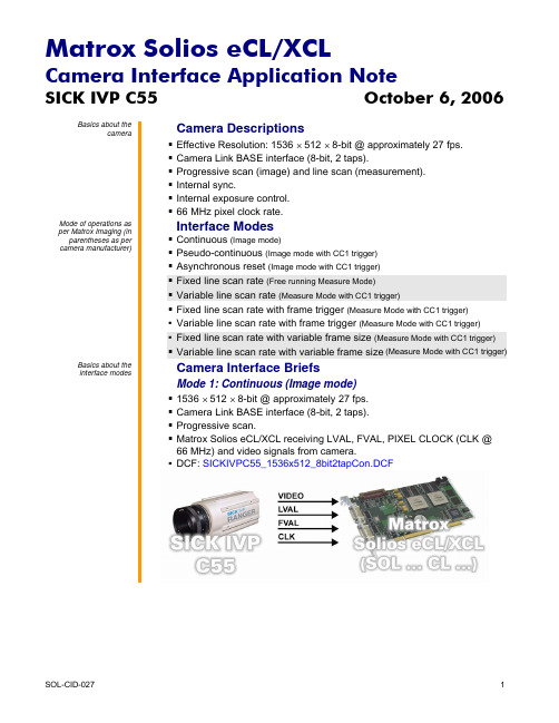
DCF used: SICKIVPC55_9216x512_8bit2tapVLSFຫໍສະໝຸດ .DCFSOL-CID-027
4
Matrox Solios eCL/XCL
Camera Interface Application Note
SICK IVP C55
camera. Matrox Solios eCL/XCL receiving LVAL, PIXEL CLOCK (CLK @ 66 MHz)
and video signals from camera. DCF used: SICKIVPC55_9216x512_8bit2tapFLS.DCF
initiate exposure time. Matrox Solios eCL/XCL receiving LVAL, FVAL, PIXEL CLOCK (CLK @
66 MHz) and video signals from camera.
DCF used: SICKIVPC55_1536x512_8bit2tapAsync.DCF
camera. Matrox Solios eCL/XCL receiving LVAL, PIXEL CLOCK (CLK @ 66 MHz)
and video signals from camera.
DCF used: SICKIVPC55_9216x512_8bit2tapVLS.DCF
Mode 9: Variable line scan rate with variable frame size
Matrox Solios eCL/XCL
Camera Interface Application Note
Quick Start Guide 快速入门指南说明书

40mm screws
3mm nuts
3. Propellers
The wings silver spinners spin clockwise and the pylons black spinners spin counter-clockwise. a) Unscrew the spinner and place the 10x5 props on the main wing motors, and the 10x5R on the pylon motors. b) Tighten the spinner by holding the motor still and spinning the spinner into place. Tighten firmly with fingers.
safety switch
c) (Ai Only) Ensure that the craft has a GPS signal by checking for a blue light inside the compass unit. d) Arm the motors by holding the throttle down and right.
*Always fly at locations that are clear of building and other obstacles. *DO NOT fly above or near large crowds. *Avoid flying at altitudes above 400 ft. *Be very careful when flying 19,600 ft. or more above sea level. *Fly in moderate weather conditions with temperatures between 32° F to 104° F.
Matrox Genesis DALSA CL-E1-1024A 相机接口指南说明书
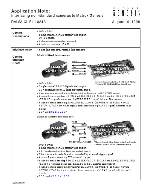
HSYNC (LVAL) and video signals from camera; a high LVAL signal indicates valid
pixels.
• DCF used: CLE1DL.DCF
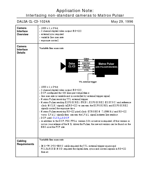
Mode 2: Variable line scan rate
VIDEO MCLK
LVAL STROBE
Application Note:
Interfacing non-standard cameras to Matrox Genesis DALSA CL-E1-1024A
August 10, 1998
Camera Descriptions
Interface mode Camera Interface Briefs
Pin no. 01 02 03 04 05 06 07 08 09 10 11 12 13 14 15 16 17 18 19 20
Pin name
→
DATA, INPUT, 7+
→
DATA, INPUT, 7-
→
DATA, INPUT, 6+
→
DATA, INPUT, 6-
Exposure Time
HSYNC (LVAL)
Video Valid = 68.3 ms
Cabling Requirements
Mode 1: Fixed line scan rate • Matrox cable kit (GEN-TO-DALSA/16) is available for this mode as an alternative to
• Line rate: The line rate is variable and controlled by the frequency of the external trigger signal.
Matrox Radient eCL摄像头接口应用指南.pdf_1705462207.4070492
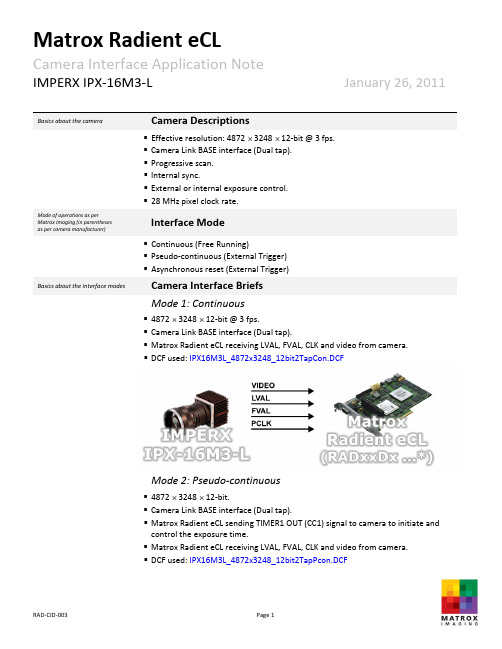
IMPERX IPX‐16M3‐L January 26, 20110031Basics about the camera Camera Descriptions▪Effective resolution: 4872 ⨯ 3248 ⨯ 12‐bit @ 3 fps. ▪Camera Link BASE interface (Dual tap).▪Progressive scan.▪Internal sync.▪External or internal exposure control.▪28 MHz pixel clock rate.Mode of operations as perMatrox Imaging (in parenthesesas per camera manufacturer)Interface Mode▪Continuous (Free Running)▪Pseudo‐continuous (External Trigger) ▪Asynchronous reset (External Trigger)Basics about the interface modes Camera Interface Briefs Mode 1: Continuous▪4872 ⨯ 3248 ⨯ 12‐bit @ 3 fps.▪Camera Link BASE interface (Dual tap).▪Matrox Radient eCL receiving LVAL, FVAL, CLK and video from camera. ▪DCF used: IPX16M3L_4872x3248_12bit2TapCon.DCFMode 2: Pseudo‐continuous▪4872 ⨯ 3248 ⨯ 12‐bit.▪Camera Link BASE interface (Dual tap).▪Matrox Radient eCL sending TIMER1 OUT (CC1) signal to camera to initiate andcontrol the exposure time.▪Matrox RadienteCL receiving LVAL, FVAL, CLK and video from camera.▪DCF used: IPX16M3L_4872x3248_12bit2TapPcon.DCFIMPERX IPX‐16M3‐L January 26, 20110032Basics about the interface m Camera Interface Briefs (cont.) Mode 2: Pseudo‐continuousMode 3: Asynchronous reset▪4872 ⨯ 3248 ⨯ 12‐bit.▪Camera Link BASE interface (Dual tap).▪Matrox Radient eCL receiving external OPTO trigger signal.▪Matrox Radient eCL sending TIMER1 OUT (CC1) signal to camera to initiate and control the exposure.▪Matrox Radient eCL receiving LVAL, FVAL, CLK and video from camera.▪DCF used: IPX16M3L_4872x3248_12bit2TapAsync.DCFSpecifics about the interfacemodesCamera Interface Details Mode 1: Continuous▪Frame rate: Matrox Radient eCL receives the continuous video from the camera at 3frames per second.▪Exposure time: Exposure time is set using the Imperx Camera Configuration Utility.Referto the camera manual for commands description and usage.IMPERX IPX‐16M3‐L January 26, 20110033Specifics about the interface modes Camera Interface Details (cont.) Mode 1: Continuous▪Camera configuration: The camera mode is set as follows using the Imperx Camera Configuration Utility. Refer to the camera manual for commands description and usage: Bit Depth = 12 bit | Output Mode = Dual tap | Trigger = OFFMode 2: Pseudo‐continuous▪Frame rate: The frame rate is determined by the frequency of the TIMER1 OUT (CC1) signal.▪Exposure time: The exposure is determined by the active duration of TIMER1 OUT (CC1), which can be modified in the DCF using Matrox Intellicam or with the MIL MdigControl() function. Consult the respective manual for more information.▪Camera configuration: The camera mode is set as follows using the Imperx Bobcat Camera Configuration Utility. Refer to the camera manual for commands description and usage: Bit Depth = 12 bits | Output Mode = Dual Taps | Trigger = CC | Mode = Standard | CC Expose Control = ComputerMode 3: Asynchronous Reset▪Frame rate: The frame rate is determined by the frequency of the external trigger signal. The period between the external trigger signals must be larger than the frame readout period plus the exposure time.▪Exposure time: Refer to Mode 2: Pseudo‐continuous.▪Camera configuration: Refer to Mode 2: Pseudo‐continuous.Cabling details for the interfacemodesCabling RequirementsMode 1 and 2: Continuous and Pseudo‐continuous ▪Cable and Connection: One Standard Camera Link cable.IMPERX IPX‐16M3‐L January 26, 20110034Cabling details for the interfacemodesCabling Requirements (cont.) Mode 3: Asynchronous Reset▪Cable and Connection: One Standard Camera Link cable.▪External trigger: External trigger should be connected to the external auxiliary I/O (connector A on Matrox Radient eCL bracket).EXTERNAL AUX. I/O(connector A) External Trigger SourcePIN NAME PIN NO. PIN NAME PIN NO.OPTO_AUX_IN0 + 15 ← SI GNAL ‐‐OPTO_AUX_IN0 ‐ 09 ← GROUND ‐‐The DCFs mentioned in this application note are also attached (embedded) to this PDF file – use the Adobe Reader’s View File Attachment to access the DCF files. The information furnished by Matrox Electronics System, Ltd. is believed to be accurate and reliable. Please verify all interface connections with camera documentation or manual. Contact your local sales representative or Matrox Sales office or Matrox Imaging Applications at 514‐822‐6061 for assistance. © Matrox Electronic Systems Ltd, 2010‐2011.Matrox Electronic Systems Ltd.1055 St. Regis Blvd.Dorval, Quebec H9P 2T4CanadaTel: (514) 685‐2630Fax: (514) 822‐6273。
华为Ascend Mate2用户快速入门指南说明书

Mate2 Quick Start GuideYour phone at a glanceThank you for choosing HUAWEI Ascend Mate2. Before you start, let's take a look at your new phone. Press the power button to turn on or turn off the screen.Installing the micro-SIM cardFollow the instructions in the figures below to install your micro-SIM card and microSD card. Then press and hold the power button to power on your phone. Do not insert or remove the micro-SIM card when your phone is powered on.1Open the battery cover.2Insert the micro-SIM card.Insert the microSD card (optional).Charge the phone.3Locking and unlocking the screen Press the power button to lock the screen.Your phone automatically locks its screen after being idle fora specified period of time. You can touch > Display > Sleep to set the screen timeout period.If the screen is off, press the power button to turn it on. Slide your finger toward any direction to unlock the screen.CallingTouch and enter a phone number on the dialer. Your phone then displays matching contacts. Touch a contact to place a call.Alternatively, touch and enter the initials or first few letters of a contact's name to quickly find the contact. From the displayed matching contacts, touch the contact you want to call.You can also touch a number from Messaging, Email, or Browser to place a call.MessagingTouch to open Messaging.Attaching a file to a text message converts the message into a multimedia message. You can save photos, audio clips, or videos from received multimedia messages.When you are typing, flick down from the status bar to openthe notification panel, and touch to switch the input method.Attach a fileCameraTouch to launch Camera .Frame the scene you want to capture, and have the phone automatically focus itself or touch the screen to focus on a specific object. Touch to take a photo or touch to shoot a video.Selectshooting modeView yourphotosSuspend buttonThe suspend button contains a variety of useful functions and shortcuts, which lets you quickly configure your phone settings or launch applications.Go to and touch Suspend button to turn on the suspend button. Touch to display the suspend button menu.Touch to display the multi-window menu. You can then launch commonly used tools without leaving the current screen.Phone ManagerPhone Manager can help you manage application permissions, optimize the system, clean up your storage, and save battery power.Touch to open Phone Manager.Flick leftfor morefunctionsMulti-screen displayYou can connect your phone to other displays to synchronize content on your phone to those displays and control the playback.Open the notification panel and turn on Multi-screen bytouching . You can then display photos or play videos and audio clips from your phone on a TV or projector. To do so requires that your TV support DLNA. If it doesn't, you can purchase the HUAWEI MediaQ or a similar wireless transmission device.More informationWant to learn more about Huawei Emotion UI? Visit / for the latest information.This guide is for reference only. The actual product,including but not limited to the color, size, and screen layout, may vary. All statements, information, andrecommendations in this guide do not constitute awarranty of any kind, express or implied.For DTS patents, see. Manufacturedunder license from DTS LicensingLimited. DTS, the Symbol, & DTS andthe Symbol together are registeredtrademarks, and DTS Sound is atrademark of DTS, Inc. © DTS, Inc. AllRights Reserved.Please visit/en/support/hotlinefor recent updated hotline and email addressin your country or region.Model: HUAWEI MT2-L02。
雷克星X5-UM无线充电器说明书
will turn on blue breathingly, and the left and right telescopic arms will automatically open after 5 seconds to wait for the mobile phone to be placed; if the product does not turn on red after power on (not turn on, flash or turn on other color lights) All indicate that there is a problem with the product, please stop using it and return it to the seller for processing).
Air vent mount
Adjust the position of the top piece of the air outlet and the rotatable clip assembly according to the position of the air outlet blade; insert the blade and select the lock switch position according to the thickness of the blade; suitable for one-key locking of the air outlet of most cars. Silicone touches the car, tighter and fits better to protect the car from scratches.
Matrox Extio 3 Series软件版本3.01.50发布说明书
Matrox® Release Notes Matrox® Extio 3 SeriesSoftware version 3.01.5020265-401-0010April 20, 2021OverviewThis document describes the current release (version 3.01.50) of the Matrox Extio 3 firmware, the On-Screen Display (OSD), and the Matrox Extio Central Managersoftware. Matrox provides these notes to describe new features, bug fixes, andimprovements to the Extio 3 Series hardware and software.First-time setup of IPSec VPN modeWhen using your devices out of the box and setting them up for the first time, theOn-Screen Display (OSD) on the Receiver (Rx) device shows an initial log-inscreen.To enable IPSec VPN mode, click IPSec VPN mode on the log-in screen. (IPSecVPN mode creates a private link between the Transmitter (Tx) and Receiver (Rx)devices over the Internet using an IPSec-enabled router on the TX host side.)For more information, see your Matrox Extio 3 Series User Guide.New features⏹Support for Internet⏹IPSec VPN mode of operation - The Extio 3 Receiver appliance integrates anIPSec VPN client⏹Network congestion control settings⏹Adjustable maximum transmission unit (MTU) settingsNotes and limitations⏹WAN or Internet – We recommend you to set the encoding quality level tolow or typical. Network conditions also vary according to the region. For anoptimal user experience, we recommend a ping time of less than 20ms and +/-10% worst case jitter. For more information, contact your Matroxrepresentative.⏹Internet only supports unicast streams. In the Matrox Extio Central Managersoftware, Unicast must be selected as the Routing scheme in the Streamingsettings.⏹Point-to-point mode– Only networked mode is supported with this release.For point-to-point mode of operation, use a different software release version.2 Matrox® Release Notes – Matrox® Extio3 Series⏹Aggregator mode– The Link Redundancy feature isn’t currently supportedwhile using aggregator mode.⏹Guest connections–With guest connections, the following aren’t currentlysupported: RS232, audio Line In, and microphone. Over Internet, guestconnections are supported at low-encoding quality settings, and with quad1080p60 or 4kp60 display setups, the Enable advanced display modes option must be enabled.⏹Firmware Updater– When downgrading the firmware from 3.00.00 to2.01.00 (or lower), the displays will go blank during the update process. Tosee the progress of the update, refer to the status LED (on the device) and the firmware updater status. [2504]⏹Extio Central Manager– Installing new units with or updating units to the2.01 firmware while the 1.00.06 Extio Central Manager is still running willresult in the updated units not listed, or listed as lost, in the UI. To correct this, uninstall the 1.00.06 version and install the 2.01 version of the Extio Central Manager software. [1781]⏹Firmware– To ensure proper functioning of your devices, the firmwareversion installed on your Tx and Rx devices must match.⏹Firmware– When updating your firmware, make sure your Extio 3 setup isusing networked mode.⏹The following features are n’t yet enabled:▪Local output support (Video out) on the Tx device is expected in an upcoming release.▪The USB connectors on the front of the Tx device are currently disabled.⏹Power management–When using an XTO3-N3408CTX or XTO3-N3208CTX card, power management on the host system is n’t currentlysupported.[1076]⏹Matrox Mura IPX Series– T his firmware release isn’t compatible withMura IPX Series software version 3.00.00 or older.⏹If all of your devices are seen and configurable in Extio Central Manager, butthe OSD of an Rx device doesn’t reflect the connections that were configured in the Connection Broker, verify that the devices all have a valid IP address and that the network ports are accessible.▪If your devices are on a unicast network, on multiple subnets, or on a WAN network, use the new Transmitter Discovery option (in ExtioCentral Manager) to detect devices that may not be automaticallydiscovered.Matrox® Release Notes – Matrox® Extio 3 Series 3⏹Dell™ Precision™ Rack R7920 Workstation or PowerEdge™ R740 – Ifyour XTO3-N3408CTX or XTO3-N3208CTX card is installed in PCIe slot 1,that slot may not work. We recommend using a slot other than slot 1. If youneed to use slot 1, you need to disable that slot. To disable the slot, enter theSystem Bios, then click Integrated Devices→Slot disablement, and makesure the slot is marked as Disabled. When you’re done, save your changes andreboot your system. [803]⏹USB devices– Some older keyboard and mouse combos that use a Bluetooth®mini-receiver are n’t supported in networked mode. [1262]⏹On some GPUs, outputs may have temporal dithering enabled. This mayresult in blocky images. To avoid this, make sure your GPU settings areconfigured to use RGB as the output color format and the maximum level (i.e.Full) as the output dynamic range. [1632]⏹Hot plugging SFP modules isn’t supported. A reboot may be required afteradding an SFP module to your device to ensure proper detection andfunctionality. [1963]⏹If you’re using an adapter to connect your monitor to your Extio 3 device,o nly active adapters (sold separately) are supported. Passive adapters aren’tsupported.⏹When using aggregator mode and switching via keyboard shortcut, the mousepointer will remain visible on all displays in the last position before the USBwas switched. [2355]⏹Windows 7 only– When using aggregator mode and mouse position, werecommend using either a single independent desktop or a stretched desktop.[2349]Known issues⏹After adding a new Tx device and configuring it using Extio Central Managersoftware, it can take up to 45 seconds for the new Tx device to appear in theOSD as an available connection option for the Rx.⏹USB – Switching while using USB 2.0 devices (i.e. USB keys, hard drives,scanners, etc.) isn’t supported and may result in lost data or devices (need tounplug/replug device to redetect). We recommend stopping all USB 2.0transfers before switching.⏹USB – Loss of connection between a Tx and an Rx (power interruption,network failure or fiber failure) while doing USB 2.0 transfers may result inlost devices (need to unplug/replug device to redetect) or lost data.⏹Firmware Updater– When the Updater has completed, a message mayappear stating that not all Extio 3 Series devices were properly updated. If this4 Matrox® Release Notes – Matrox® Extio 3 Seriesoccurs, close the updater and re-launch it. If the devices report that they need an update, proceed with the update. If the update fails again, please contactMatrox Technical Support.⏹After updating your firmware, one of the displays connected to your Rx maybe lost. To fix this, we recommend you turn off the monitor and then turn it on again.⏹After rebooting your Tx or Rx, one of your displays may be lost. To fix this,we recommend you turn off the monitor, and then turn it on again.⏹Wake-on-LAN– N3408CTX and N3208CTX cards support wake-on-LAN. ⏹Wake-on-LAN– When using the wake-on-LAN feature with an N3408CTXor N3208CTX card installed in HP Z440 workstations, the devices maybecome unresponsive and require the system to be rebooted. [1819]Matrox® Release Notes – Matrox® Extio 3 Series 5Contact usThe Matrox web site has product literature, press releases, technical material, a sales office list, trade show information, and other relevant material. Visit us at/video.If you have any questions or comments about our products or solutions, contact us at /video/contact.Matrox values your business and offers professional support for your Matroxproduct. For more information, contact your Matrox representative or our technical support at *********************.6 Matrox® Release Notes – Matrox® Extio 3 SeriesDisclaimerInformation in this document may contain technical inaccuracies or typographicalerrors. Information may be changed or updated without notice. Matrox reserves theright to make improvements and/or changes in the products, programs and/orspecifications described in this information at any time without notice. Alltrademarks and trade names, service marks and logos referenced herein belong totheir respective owners.Bluetooth is a registered trademark of Bluetooth SIG, Inc.Dell, Precision, and PowerEdge are trademarks or registered trademarks of Dell Inc.or its subsidiaries.Linux is a registered trademark of Linus Torvald in the United States and in othercountries.MacOS is a trademark of Apple Inc., registered in the U.S. and other countries.Microsoft, Windows, and Active Directory are registered trademarks of MicrosoftCorporation in the United States and/or other countries.Copyright © 2021 Matrox is a trademark of Matrox Electronic Systems Ltd. Allrights reserved.Matrox® Release Notes – Matrox® Extio 3 Series 7Matrox Graphics Inc.1055 Saint Regis Boulevard Dorval, Quebec, CanadaH9P 2T4(514) 822-6000 **************** /video。
Matrox Pulsar DALSA CL-C3-1024A相机接口应用指南说明书
DALSA CL-C3-1024A May 29, 1996DALSA CL-C3-1024A May 29, 1996Cabling Requirements (Continued)•the connections between the OS1 20-pin dual row connector of the camera and the 68-pin SCSI-2 connector of the PULSAR/DIG/MOD are as follows:DALSA CL-C3-1024A PULSAR/DIG/MOD(20-pin dual row connector - OS1)(68-pin SCSI-2 connector)Pin name Pin no. Pin name Pin no.AD7+1→DATA7+10AD7−2→DATA7−44AD6+3→DATA6+11AD6−4→DATA6−45AD5+5→DATA5+13AD5−6→DATA5−47AD4+7→DATA4+14AD4−8→DATA4−48AD3+9→DATA3+15AD3−10→DATA3−49AD2+11→DATA2+16AD2−12→DATA2−50AD1+13→DATA1+19AD1−14→DATA1−53AD0+15→DATA0+20AD0−16→DATA0−54STROBE+17→CLKIN+29STROBE−18→CLIKIN−63LVAL+19→HSYNC+26LVAL−20→HSYNC−60•the connections between the OS2 20-pin dual row connector of the camera and the 68-pin SCSI-2 connector of the PULSAR/DIG/MOD are as follows:DALSA CL-C3-1024A PULSAR/DIG/MOD(20-pin dual row connector - OS2)(68-pin SCSI-2 connector)Pin name Pin no. Pin name Pin no.BD7+1→DATA15+2BD7−2→DATA15−36BD6+3→DATA14+3BD6−4→DATA14−37BD5+5→DATA13+4BD5−6→DATA13−38BD4+7→DATA12+5BD4−8→DATA12−39BD3+9→DATA11+6BD3−10→DATA11−40BD2+11→DATA10+7BD2−12→DATA10−41BD1+13→DATA9+8BD1−14→DATA9−42BD0+15→DATA8+9BD0−16→DATA8−43DALSA CL-C3-1024A 29/05/96DALSA CL-C3-1024A May 29, 1996DALSA CL-C3-1024A 29/05/96 When timer1 reaches the value set for CTRL_T1START, the EXPOSURE1 signal beingsent to the camera goes high. When timer1 reaches zero, the EXPOSURE1 signal goeslow. The EXPOSURE1 signal should be sent immediately to the camera upon arrival ofan external trigger signal to indicate that exposure should begin, thereforeCTRL_SET1CNT and CTRL_T1START must be set equal to each other; this isaccomplished by setting CTRL_SET1CNTL equal to CTRL_T1STARTL andCTRL_SET1CNTH equal to CTRL_T1STARTH. The Pulsar indicates to the camerathat exposure should stop by sending the EXPOSURE2 pulse. For a given setting ofCTRL_SET2CNT, which is the time set on the timer for EXPOSURE2 (timer2), the timeat which the EXPOSURE2 pulse is sent is controlled by CTRL_T2START, the width ofthe EXPOSURE2 pulse. Timer2 starts counting down from CTRL_SET2CNT; when itreaches the value set for CTRL_T2START, the EXPOSURE2 signal being sent to thecamera goes high. When timer2 reaches zero, the EXPOSURE2 signal goes low. Sinceboth timers start at the same time, the exposure time is then CTRL_SET2CNT −CTRL_T2START. Finally, it should be noted that the EXPOSURE1 pulse must remainhigh until the LVAL pulse goes low; therefore the time set on timer1 (CTRL_SET1CNT)must be greater than the exposure time, plus the maximum possible delay between theEXPOSURE2 pulse and the LVAL pulse, plus the width of the LVAL pulse (the linetransfer time). The maximum possible delay between the EXPOSURE2 pulse and theLVAL pulse is taken to be 8.9µs (64 pixel times at a clock rate of 7.159 MHz); the linetransfer time is 71.5µs (512 pixel times, since there are two outputs, at a clock rate of7.159 MHz).So to summarize:CTRL_T1START = CTRL_SET1CNT, i.e., CTRL_T1STARTL = CTRL_SET1CNTLand CTRL_T1STARTH = CTRL_SET1CNTH EXPOSURE TIME = CTRL_SET2CNT − CTRL_T2STARTCTRL_SET1CNT > exposure time + maximum delay between EXPOSURE2 andLVAL pulses (8.9µs or 64 pixels) + line transfer time (71.5µsor 512 pixels)Remember that each 16-bit register is split into a low byte and a high byte. These valuesmust be in pixels and must be set in hexadecimal; the value of each 16-bit register canvary between 0 (0000 in Hex) and 65 535 (FFFF in Hex). The default time set on timer1as well as the default width of the EXPOSURE1 pulse is 6400 pixels, which inhexadecimal is 1900 (Here the low byte corresponds to 0H and the high byte to 19H).The default time set on timer2 is 6144 pixels (1800H) and the default width of theEXPOSURE2 pulse is 256 pixels (100H). The default exposure time is therefore6144 − 256 = 5888 pixels, which at a clock rate of 7.159MHz corresponds to 0.82ms.The registers are set in the following way:CTRL_SET1CNTL0H CTRL_SET2CNTL0HCTRL_SET1CNTH19H CTRL_SET2CNTH18HCTRL_T1STARTL0H CTRL_T2STARTL0HCTRL_T1STARTH19H CTRL_T2STARTH1HDALSA CL-C3-1024AMay 29, 1996When computing the hardware registers, the following question may be asked: “Some registers have been manually edited. Ok to overwrite them all? (y/n)”. Answer “no” to this question and to all questions that follow.IMPORTANT! These instructions must be followed very carefully ; the only registers that should be modified are those mentioned above . Please consult Matrox Imaging Applications at (514) 822-6061 if assistance is required.•the maximum trigger rate is the reciprocal of the width of the EXPOSURE1 pulse, or in other words, it is the reciprocal of the sum of the exposure time and 80.4µs. This last number is the sum of the maximum delay between the EXPOSURE2 and LVAL pulses (taken to be 8.9µs) and the line transfer time (71.5µs). The default max trigger rate is 1.1kHz•an RS-422 external trigger input may also be used once the following connectionsbetween the 68-pin SCSI-2 connector of the PULSAR/DIG/MOD and the external trigger source are made:PULSAR/DIG/MODExternal trigger source (68-pin SCSI-2 connector)Pin name Pin no. Pin nameTRIGGER+27←“RS-422 TRIGGER+”TRIGGER-61←“RS-422 TRIGGER-”•use Matrox Intellicam in order to modify the DCF for an RS-422 external trigger input.Consult the Matrox Intellicam User Guide for more informationThe DCF(s) mentioned in this application note can be found on the MIL and MIL-Lite CD, or our FTP site ().The information furnished byMatrox Electronics System, Ltd. is believed to be accurate and reliable. Please verify all interface connections with camera documentation or manual.Contact your local sales representative or Matrox Sales office or Matrox Imaging Applications at 514-822-6061 for assistance.CorporateHeadquarters:Canada and U.S.A.Matrox Electronic Systems Ltd.1055 St.Regis Blvd.Dorval, Quebec, Canada H9P 2T4Tel: (514) 685-7230Fax: (514) 822-6273。
Matrox Odyssey Xpro相机接口应用指南说明书
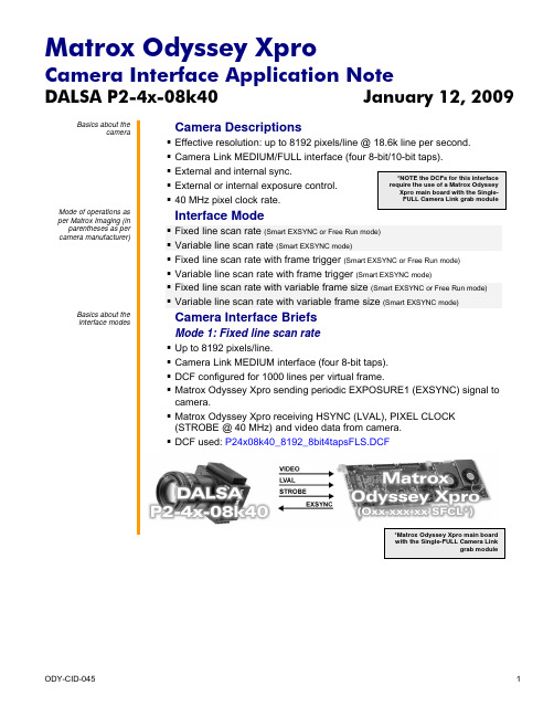
DALSA P2-4x-08k40 January 12, 2009Basics about thecamera Camera Descriptions▪▪ Camera Link MEDIUM/FULL interface (four 8-bit/10-bit taps).▪ External and internal sync.▪ External or internal exposure control. ▪ 40 MHz pixel clock rate. Mode of operations asper Matrox Imaging (in parentheses as percamera manufacturer) Interface Mode ▪ Fixed line scan rate (Smart EXSYNC or Free Run mode)▪ Variable line scan rate (Smart EXSYNC mode)▪ Fixed line scan rate with frame trigger (Smart EXSYNC or Free Run mode)▪ Variable line scan rate with frame trigger (Smart EXSYNC mode) ▪ Fixed line scan rate with variable frame size (Smart EXSYNC or Free Run mode)▪ Variable line scan rate with variable frame size (Smart EXSYNC mode)Basics about theinterface modes Camera Interface BriefsMode 1: Fixed line scan rate▪ Up to 8192 pixels/line.▪ Camera Link MEDIUM interface (four 8-bit taps).▪ DCF configured for 1000 lines per virtual frame.▪ Matrox Odyssey Xpro sending periodic EXPOSURE1 (EXSYNC) signal tocamera.▪ Matrox Odyssey Xpro receiving HSYNC (LVAL), PIXEL CLOCK(STROBE @ 40 MHz) and video data from camera.▪ DCF used: P24x08k40_8192_8bit4tapsFLS.DCFDALSA P2-4x-08k40 January 12, 2009 Basics about theCamera Interface Briefs (continued)interface modesMode 2: Variable line scan rate▪ Up to 8192 pixels/line.▪ Camera Link MEDIUM interface (four 8-bit taps).▪ DCF configured for 1000 lines per virtual frame.▪ Matrox Odyssey Xpro receiving external TTL line trigger signal.▪ Matrox Odyssey Xpro sending EXPOSURE1 (EXSYNC) signal tocamera.▪ Matrox Odyssey Xpro receiving HSYNC (LVAL), PIXEL CLOCK(STROBE @ 40 MHz) and video data from camera.▪ DCF used: P24x08k40_8192_8bit4tapsVLS.DCFMode 3: Fixed line scan rate with frame trigger▪ Up to 8192 pixels/line.▪ Camera Link MEDIUM interface (four 8-bit taps).▪ DCF configured for 1000 lines per virtual frame.▪ Matrox Odyssey Xpro receiving external TTL frame (virtual) trigger signal.▪ Matrox Odyssey Xpro sending periodic EXPOSURE1 (EXSYNC) signal tocamera.▪ Matrox Odyssey Xpro receiving HSYNC (LVAL), PIXEL CLOCK(STROBE @ 40 MHz) and video data from camera.▪ DCF used: P24x08k40_8192_8bit4tapsFLSFT.DCFDALSA P2-4x-08k40 January 12, 2009 Basics about theCamera Interface Briefs (continued)interface modesMode 4: Variable line scan rate with frame trigger▪ Up to 8192 pixels/line.▪ Camera Link MEDIUM interface (four 8-bit taps).▪ DCF configured for 1000 lines per virtual frame.▪ Matrox Odyssey Xpro receiving external TTL frame (virtual) and linetrigger signals.▪ Matrox Odyssey Xpro sending EXPOSURE1 (EXSYNC) signal tocamera.▪ Matrox Odyssey Xpro receiving HSYNC (LVAL), PIXEL CLOCK(STROBE @ 40 MHz) and video data from camera.▪ DCF used: P24x08k40_8192_8bit4tapsVLSFT.DCFMode 5: Fixed line scan rate with variable frame size▪ Up to 8192 pixels/line.▪ Camera Link MEDIUM interface (four 8-bit taps).▪ DCF configured for 1000 lines per virtual frame.▪ Matrox Odyssey Xpro receiving external TTL frame (virtual) trigger signal.▪ Matrox Odyssey Xpro sending periodic EXPOSURE1 (EXSYNC) signal tocamera.▪ Matrox Odyssey Xpro receiving HSYNC (LVAL), PIXEL CLOCK(STROBE @ 40 MHz) and video data from camera.▪ DCF used: P24x08k40_8192_8bit4tapsFLSVF.DCFDALSA P2-4x-08k40 January 12, 2009Basics about theinterface modes Camera Interface Briefs (continued)Mode 6: Variable line scan rate with variable frame size▪ Up to 8192 pixels/line.▪ Camera Link MEDIUM interface (four 8-bit taps).▪ DCF configured for 1000 lines per virtual frame.▪ Matrox Odyssey Xpro receiving external TTL frame (virtual) and linetrigger signals.▪ Matrox Odyssey Xpro sending EXPOSURE1 (EXSYNC) signal tocamera.▪ Matrox Odyssey Xpro receiving HSYNC (LVAL), PIXEL CLOCK(STROBE @ 40 MHz) and video data from camera.▪ DCF used: P24x08k40_8192_8bit4tapsVLSVF.DCFSpecifics about theinterface modes Camera Interface DetailsMode 1: Fixed line scan rate▪ Line rate: The frequency of the periodic EXPOSURE1 (EXSYNC) signal determines the camera’s line rate. The EXPOSURE1 (EXSYNC) signalperiod is set in the DCF to 183 μs which translates into a 2.31 kHz linerate. The maximum line rate for this camera equals 18.6 kHz .▪ Exposure time: For Smart EXSYNC mode the exposure time is theinactive (high level) period between the rising and falling edges of the EXPOSURE1 (EXSYNC) signal. The default exposure time for this DCFequals 130 μs . Maximum/minimum exposure time per line for this DCF is420 ms and 50 ns respectively. The exposure time can be modified in theDCF using Matrox Intellicam, ONL imCamControl() or imDigControl()function, or with the MIL MdigControl() function. Consult the respectivemanual for more information. ▪Inverted tap output: The camera’s tap output configuration featuresmirrored taps of which one tap will need to be inverted. Matrox OdysseyXpro supports hardware tap inversion, which has been enabled in theDCF.DALSA P2-4x-08k40 January 12, 2009 Specifics about theCamera Interface Details (continued)interface modesMode 1: Fixed line scan rate▪Camera communication: This DCF will work with Free Run and SmartEXSYNC modes. Set the mode (as shown in table below) via the CameraLink communication. Refer to the camera manual for additionalinformation.Command Short Form Parameter DescriptionSet_exposure_mode sem 1 or 2 Free RunSet_exposure_mode sem 4 Smart EXSYNC modeMode 2: Variable line scan rate▪Line rate: The line rate is controlled by the frequency of the external TTLline trigger signal. The line trigger signal period must be larger than thetotal duration of the exposure time (high level duration of the timer), theinternal delay of the camera (≈1.50 μs) and the line read out (51.3 μs).▪Exposure time: Refer to Mode 1: Fixed line scan rate.▪Inverted tap output: Refer to Mode 1: Fixed line scan rate.▪Camera communication: Set the mode (as shown in table below) via theCamera Link communication. Refer to the camera manual for additionalinformation.Command Short Form Parameter DescriptionSet_exposure_mode sem 4 Smart EXSYNC mode▪Timing diagram:Mode 3: Fixed line scan rate with frame trigger▪Line/frame rate: The line rate is fixed and controlled by the period ofEXPOSURE1 (EXSYNC) signal. The virtual frame rate is variable andcontrolled by the period of the external frame trigger signal, however theexternal trigger period must always be greater than the total time of thenumber of lines captured. The number of lines per virtual frame(maximum of 1000 for this DCF) is fixed and controlled by the verticaltiming of the DCF. Capture of the lines will start with the rising edge of theframe trigger signal.▪Exposure time: Refer to Mode 1: Fixed line scan rate.Continued…DALSA P2-4x-08k40 January 12, 2009 Specifics about theCamera Interface Details (continued)interface modesMode 3: Fixed line scan rate with frame trigger▪E xposure time: Refer to Mode 1: Fixed line scan rate.▪I nverted tap output: Refer to Mode 1: Fixed line scan rate.▪Camera communication: Refer to Mode 1: Fixed line scan rate.▪Timing diagram:Mode 4: Variable line scan rate with frame trigger▪Line/frame rate: The line rate is controlled by the frequency of theexternal TTL line trigger signal. The line trigger signal period must belarger than the total duration of the exposure time (high level duration ofthe timer), the internal delay of the camera (≈1.50 μs) and the line rate(51.3 μs). The virtual frame rate is variable and controlled by the period ofthe external frame trigger signal, however the external trigger period mustalways be greater than the total time of the number of lines captured. Thenumber of lines per virtual frame (maximum of 1000 for this DCF) is fixedand controlled by the vertical timing of the DCF. Capture of the lines willstart with the rising edge of the frame trigger signal.▪Exposure time: Refer to Mode 1: Fixed line scan rate.▪Inverted tap output: Refer to Mode 1: Fixed line scan rate.▪Camera communication:Refer to Mode 2: Variable line scan rate.▪Timing diagram:DALSA P2-4x-08k40 January 12, 2009 Specifics about theCamera Interface Details (continued)interface modesMode 5: Fixed line scan rate with variable frame size▪Line/frame rate: The line rate is fixed and controlled by the period ofEXPOSURE1 (EXSYNC) signal. The number of lines per virtual frame(maximum of 1000 for this DCF) is variable and controlled by the frametrigger signal. Matrox Odyssey captures lines during the high level of theframe trigger signal. To modify the maximum amount of lines captured,change the active vertical timing period in the DCF. Capture of the lineswill start with the rising edge of the frame trigger signal.▪Exposure time: Refer to Mode 1: Fixed line scan rate.▪Inverted tap output: Refer to Mode 1: Fixed line scan rate.▪Camera communication:Refer to Mode 1: Fixed line scan rate.▪Timing diagram:Mode 6: Variable line scan rate with variable frame size▪Line/frame rate: The line rate is variable and controlled by the externalline trigger frequency. The number of lines per virtual frame (maximum of1000 for this DCF) is variable and controlled by the frame trigger signal.Matrox Odyssey captures lines during the high level of the frame triggersignal. To modify the maximum amount of lines captured, change theactive vertical timing period in the DCF. Capture of the lines will start withthe rising edge of the frame trigger signal.▪Exposure time: Refer to Mode 1: Fixed line scan rate.▪Inverted tap output: Refer to Mode 1: Fixed line scan rate.▪Camera communication:Refer to Mode 2: Variable line scan rate.Continued…DALSA P2-4x-08k40 January 12, 2009 Specifics about theCamera Interface Details (continued)interface modesMode 6: Variable line scan rate with variable frame size▪Timing diagram:Cabling details for theCabling Requirementsinterface modesMode 1: Fixed line scan rate▪Cable and Connection: Standard Camera Link cable.Mode 2: Variable line scan rate▪Cable and Connection: Standard Camera Link.▪External trigger: External line trigger should be connected to the OPTOTRIG input of the 9-pin connector (pins 7 and 2) on the External I/Oadapter bracket:EXTERNAL I/O BRACKET(9-pin connector) External Trigger SourcePin Name Pin no. Pin NameOPTO_AUX_IN0 + 07 ←LINE TRIGGER (TTL FORMAT)OPTO_AUX_IN0 - 02 ←LINE TRIGGER (GROUND)Mode 3: Fixed line scan rate with frame trigger▪Cable and Connection: Standard Camera Link.▪External trigger: External line trigger should be connected to the OPTOTRIG input of the 9-pin connector (pins 4 and 5) on the External I/Oadapter bracket:EXTERNAL I/O BRACKET(9-pin connector) External Trigger SourcePin Name Pin no. Pin NameOPTO_AUX_IN1 + 04 ←FRAME TRIGGER (TTL FORMAT)OPTO_AUX_IN1 - 05 ←FRAME TRIGGER (GROUND)Matrox Odyssey XproCamera Interface Application NoteDALSA P2-4x-08k40 January 12, 2009 Cabling details for theCabling Requirementsinterface modesMode 4: Variable line scan rate with frame trigger▪Cable and Connection: Standard Camera Link.▪External trigger: External frame and line triggers should be connected to theOPTO TRIG inputs of the 9-pin connector on the External I/O adapterbracket:EXTERNAL I/O BRACKET(9-pin connector) External Trigger SourcesPin name Pin no. Pin nameOPTO_AUX_IN1 + 04 ←FRAME TRIGGER (TTL FORMAT)OPTO_AUX_IN1 - 05 ←FRAME TRIGGER (GROUND)OPTO_AUX_IN0 + 07 ←LINE TRIGGER (TTL FORMAT)OPTO_AUX_IN0 - 02 ←LINE TRIGGER (GROUND)Mode 5: Fixed line scan rate with variable frame size▪Cable and Connection: Standard Camera Link.▪External trigger: External trigger should be connected to the OPTO TRIGinput (pins 4 and 5) of the 9-pin connector on the External I/O adapterbracket:EXTERNAL I/O BRACKET(9-pin connector) External Trigger SourcesPin name Pin no. Pin nameOPTO_AUX_IN1 + 04 ←FRAME TRIGGER (TTL FORMAT)OPTO_AUX_IN1 - 05 ←FRAME TRIGGER (GROUND)Mode 6: Variable line scan rate with variable frame size▪Cable and Connection: Standard Camera Link.▪External trigger: External frame and line triggers should be connected to theOPTO TRIG inputs of the 9-pin connector on the External I/O adapterbracket:EXTERNAL I/O BRACKET(9-pin connector) External Trigger SourcesPin name Pin no. Pin nameOPTO_AUX_IN1 + 04 ←FRAME TRIGGER (TTL FORMAT)OPTO_AUX_IN1 - 05 ←FRAME TRIGGER (GROUND)OPTO_AUX_IN0 + 07 ←LINE TRIGGER (TTL FORMAT)OPTO_AUX_IN0 - 02 ←LINE TRIGGER (GROUND)The DCFs mentioned in this application note are also attached (embedded) to this PDF file – use the Adobe Reader’s View File Attachment to access the DCF files. The information furnished by Matrox Electronics System, Ltd. is believed to be accurate and reliable. Please verify all interface connections with camera documentation or manual. Contact your local sales representative or Matrox Sales office or Matrox Imaging Applications at 514-822-6061 for assistance. © Matrox Electronic Systems Ltd, 2009-2011.Matrox Electronic Systems Ltd.1055 St. Regis Blvd.Dorval, Quebec H9P 2T4CanadaTel: (514) 685-2630Fax: (514) 822-6273。
百胜奇才使用手册

百胜奇才使用手册Post By:2007-12-17 16:36:00MEGAS GPX 超声诊断仪是百胜公司于2003 年初推出的一款代表当今世界领先技术的全身应用超声诊断设备。
它具有优质的二维图象、敏感的彩色血流、强大的谐波功能、领先的独立变频技术等诸多特点同时它又及时跟踪当今医疗环境的变化,机身设计的轻盈小巧,便于移动,加之双显示模式,使您的检查空间不在局限于超声科,更可以延伸至床旁、急救车、急诊室、手术室及病人家中。
高密度探头,加之宽频带+变频+独立变频技术,使您在遇见各种病人时更显得心应手,从容不迫。
此台设备更具能量图及方向性能量图,在您面对低速血流时游刃有余。
方便的DAM 存储系统,使您的每一幅宝贵图象得以永久保存。
钛合金的穿刺引导装置,适用于各种消毒方式,使您的介入诊断治疗如虎添翼。
基本键盘功能介绍键盘分区:功能区:功能区:功能区:测量功能介绍二维下的距离、面积测量:在二维下冻结图象,如需要测量距离可直接按。
进行距离测量,按键进行面积测量。
其他参数测量如要进行其他测量,则在冻结图像后直接按MEASURE键,出现右图,用轨迹球选择所需要项目,如面积、体积、角度:1. 冻结图像,触发MEASURE 后,2. 此时可根据需要用轨迹球选择您的测量选项,并用ENTER 键确认13. AREA (E)椭圆面积法AREA (P)手动描绘测面积法VOLUME (E)椭圆体积法VOLUME (A/D)面积乘直径测体积法VOLUME (Bi)三条直径测体积法ANGLES 角度测量M型测量:在M 下冻结图像,如需要测量速度可直接按进行径线测量。
其他参数测量如要进行其他测量,则在冻结图像后直接按MEASURE 键,出现右图,用轨迹球选择所需要项目,如TI ME 时间、HEART RATE 心率、SLOPE 斜率等等,并用ENTER 键确认多普勒测量:(如图2)在PW/CW 下冻结图像,如需要测量速度可直接按。
FastTrak SX4000 Quick Start Guide.pdf_1697843059.6

FastTrak SX4000 Quick Start GuideVersion 2.0FastTrak SX4000Copyright© 2002, Promise Technology, Inc.Copyright by Promise Technology, Inc. (Promise Technology). No part of this manual may be reproduced or transmitted in any form without the expressed, written perm ission of Promise Technology.TrademarksPromise, and the Promise logo are registered in U.S. Patent and TrademarkOffice. All other product names mentioned herein may be trademarks orregistered trademarks of their respective companies.Important data protection informationYou should back up all data before installing any drive controller or storageperipheral. Promise Technology is not responsible for any loss of data resulting from the use, disuse or misuse of this or any other Promise Technology product. NoticeAlthough Promise Technology has attempted to ensure the accuracy of thecontent of this manual, it is possible that this document may contain technical inaccuracies, typographical, or other errors. Promise Technology assumes no liability for any error in this publication, and for damages, whether direct, indirect, incidental, consequential or otherwise, that may result from such error, including, but not limited to loss of data or profits.Promise Technology provides this publication “as is” without warranty of anykind, either express or implied, including, but not limited to implied warranties of merchantability or fitness for a particular purpose.The published information in the manual is subject to change without notice.Promise Technology reserves the right to make changes in the product design, layout, and driver revisions without notification to its users.ContentsStep 1: Unpack your FastTrak (3)Step 2: FastTrak Card Installation (4)Step 3: Connect the Hard Drives (5)Step 4: Create an Array (6)Step 5:Driver Installation (8)Quick Start Guide Step 1: Unpack your FastTrakOpen the FastTrak box and carefully remove the FastTrak card and accessories from the box. The FastTrak SX4000 package should contain the following items:•FastTrak SX4000 Controller Card•FastTrak SX4000 Quick Start Guide•FastTrak SX4000 OS drivers diskette (1)•CD containing Utilities and Documentation (1)•Internal 18 inch (46 cm) Ultra ATA, 80-wire/40-pin hard drive cables (4)•Y-cable power splitters (2)If any of the items are missing or appear damaged, please contact your dealer or distributor immediately.AttentionThe FastTrak SX4000 controller card, like many other parts of your PC, is sensitive to static electricity. Be sure that you are properly grounded (Promise recommends that you wear an anti-static strap, or place a free hand on a grounded object), and that your PC is unplugged before installing any of the FastTrak SX4000 components.FastTrak SX4000Step 2: FastTrak Card InstallationFigure 1. FastTrak SX4000 controller card1. Install a DIMM memory chip into the slot at DIMM1. The minimummemory requirement is 64 MB.You may use up to 256 MB ECC or non-ECC, unbuffered 168-pin PC100 or higher SDRAM.2. Install the controller card into an available PCI slot on the systemmotherboard and secure it to the PC’s chassis.Quick Start GuideStep 3: Connect the Hard Drives1. Set your hard drives to Master, Cable-Select or Single (depending ondrive specification).2. Install your hard drives into the PC chassis.3. Attach the black end of Ultra ATA cable to the ATA connector of eachdrive.4. Attach a power cable to the power connector of each drive.5. Connect the blue end of the Ultra AT A cable to any available ATAchannel on the FastTrak SX4000.NoteDevice support for drives is provided by the FastTrak SX4000 system. No changes are necessary in the motherboard CMOS/BIOS Setup for resources or drive types regarding hard drive configuration.Step 4: Create an ArrayAppendix A of the FastTrak SX4000 User’s Manual contains an explanation of RAID Levels. If you are new to RAID, you may wish to read about it before creating your first array.1. Boot your computer and watch for the Promise FastTrak SX4000 BIOSto appear (below).Figure 2. FastTrak BIOS Screen.2. Press Ctrl-F to open the Configuration Utility. The Main Menu appears(below).Figure 3. Array Utility Opening Screen.3. Use the FastBuild utility to create at least one array on the drive(s)attached to the FastTrak SX4000 card.Select View/Define Array... [ 2 ]. The Define Array screen appears(below).Quick Start GuideFigure 4. Define Array Menu.4. Press the arrow keys to highlight an Array Number then press Enter toselect it. The Array Definition menu appears (below).Figure 5. Array Definition Menu.5. Press the arrow keys to highlight RAID Level and drives for the array.Press the Spacebar to switch among available options.Promise recommends keeping the default values for Stripe Block andGigabyte Boundary unless you have specific reasons for changing them. The FastTrak SX4000 User’s Manual contains an explanation of these features.6. Press Ctrl-Y to save your selection. The Define Array Menu (Figure 5)reappears.7. Press Esc to exit or Enter to select another array to build.8. Restart your computer to make the array available.9. Partition and format the array as you would an individual hard drive.The array is now ready for use.FastTrak SX4000Step 5: Driver InstallationThis section details the FastTrak SX4000 driver installation when used with various operating systems. The software includes the driver necessary to identify FastTrak SX4000 to the operating system.Installing Driver During New Windows XP Installation 1. Start the installation: Boot from the CD-ROM. Press F6 after themessage “Press F6 if you need to install third party SCSI or RAID driver”appears.2. When the Windows XP Setup window is generated, press S to specifyan Additional Device(s)3. Insert the Promise Technology driver diskette into drive A: and pressEnter.4. Choose WinXP Promise FastTrak SX4000™ Series Controller from thelist that appears on screen, and then press the Enter.5. Press S to use the driver on the floppy disk and then press Enter tocontinue with installation.6. The Windows XP Setup screen will appear again saying “Setup will loadsupport for the following mass storage devices:” The list will includeWinXP Promise FastTrak SX4000™ Series Controller.NOTE: If you need to specify any additional devices to be installed, do so at this time. Once all devices are specified, continue to the next step.7. From the Windows XP Setup screen, press the Enter. Setup will nowload all device files and then continue the Windows XP installation.Quick Start GuideInstalling Driver in Existing Windows XP SystemWarningIf you plan to move the boot drive containing the existing Windows XPoperating system to the FastTrak SX4000 card, you MUST load theFastTrak SX4000 driver to the boot drive while it is still attached toyour existing hard drive controller.Do not attach the boot drive to the FastTrak SX4000 controller cardbefore completing this step.After installing the FastTrak SX4000 card and rebooting your system, Windows XP setup will show a Found New Hardware dialog box. Under Windows XP, Mass Storage Controller will be displayed.1. Insert the FastTrak SX4000 driver diskette into the A: drive.2. Choose Install the software automatically and press the Enter.3. Choose WinXP Promise FastTrak SX4000™ Series Controller from thelist that appears on screen then press Enter.4. If you are using a driver that has not been digitally signed by Microsoft,you will be asked if you want to continue the installation. Click onContinue anyway.5. When the New Hardware Wizard has finished installing the Promisesoftware, click on Finish.Confirming Windows XP Installation1. From Windows XP, open the Control Panel from My Computer.2. Click on Performance and maintenance.3. Click on the System icon.4. Choose the H ardware tab, and then click the Device Manager tab.5. Click the + in front of SCSI controllers. WinXP Promise FastTrakSX4000™ Series Controller should appear.Other Operating SystemsFor information on installing FastTrak drivers on earlier versions of Windows and other operating systems, see the User’s Manual on the CD that was included with your FastTrak SX4000.。
Matrox Genesis摄像头接口应用指南说明书
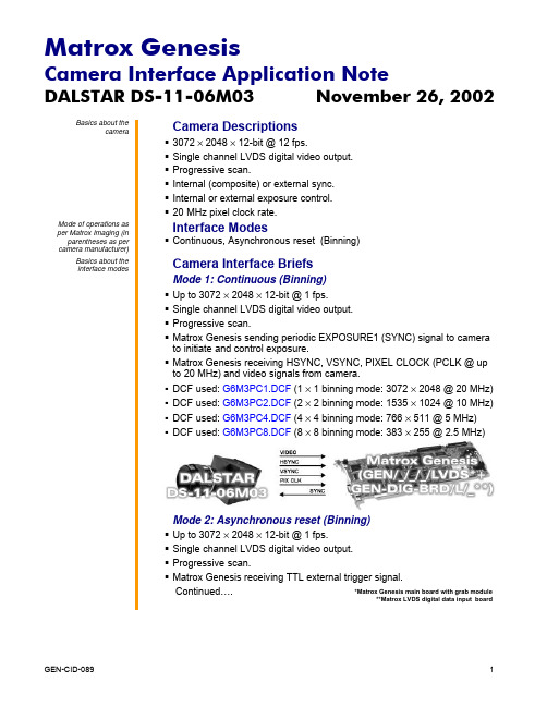
DALSTAR DS-11-06M03 November 26, 2002 Basics about thecameraCamera Descriptions§ 3072 × 2048 × 12-bit @ 12 fps.§ Single channel LVDS digital video output.§ Progressive scan.§ Internal (composite) or external sync.§ Internal or external exposure control.§ 20 MHz pixel clock rate.Mode of operations as per Matrox Imaging (in parentheses as per camera manufacturer)Interface Modes§ Continuous, Asynchronous reset (Binning)Basics about theinterface modesCamera Interface BriefsMode 1: Continuous (Binning)§ Up to 3072 × 2048 × 12-bit @ 1 fps.§ Single channel LVDS digital video output.§ Progressive scan.§ Matrox Genesis sending periodic EXPOSURE1 (SYNC) signal to camerato initiate and control exposure.§ Matrox Genesis receiving HSYNC, VSYNC, PIXEL CLOCK (PCLK @ upto 20 MHz) and video signals from camera.§DCF used: G6M3PC1.DCF (1 × 1 binning mode: 3072 × 2048 @ 20 MHz)§DCF used: G6M3PC2.DCF (2 × 2 binning mode: 1535 × 1024 @ 10 MHz)§DCF used: G6M3PC4.DCF (4 × 4 binning mode: 766 × 511 @ 5 MHz)§DCF used: G6M3PC8.DCF (8 × 8 binning mode: 383 ×Mode 2: Asynchronous reset (Binning)§ Up to 3072 × 2048 × 12-bit @ 1 fps.§ Single channel LVDS digital video output.§ Progressive scan.§ Matrox Genesis receiving TTL external trigger signal.Continued…. *Matrox Genesis main board with grab module**Matrox LVDS digital data input boardDALSTAR DS-11-06M03 November 26, 2002Basics about the interface modesCamera Interface Briefs (continued)Mode 2: Asynchronous reset (Binning)§ Matrox Genesis sending periodic EXPOSURE1 (SYNC) signal to camera to initiate and control exposure.§ Matrox Genesis receiving HSYNC, VSYNC, PIXEL CLOCK (PCLK @ up to 20 MHz) and video signals from camera.§ DCF used: G6M3PA1.DCF (1 × 1 binning mode: 3072 × 2048 @ 20 MHz) § DCF used: G6M3PA2.DCF (2 × 2 binning mode: 1535 × 1024 @ 10 MHz) § DCF used: G6M3PA4.DCF (4 × 4 binning mode: 766 × 511 @ 5 MHz) § DCF used: G6M3PA8.DCF (8 × 8 binning mode: 383 ×**********)Specifics about the interface modesCamera Interface DetailsMode: Continuous (Binning)§ Frame Rate: The frame rate is determined by the frequency of theexternal trigger signal. Default rate is 1 frame per second. To change the frame rate, adjust the total exposure period (active and inactive portions) in Matrox Intellicam. For a list of maximum possible frame rates per binning mode, refer to the camera specifications.§ Exposure time: The active period of the EXPOSURE1 (SYNC) signal is the exposure time. The default exposure time is equal to 300 ms . The exposure time can be modified in the DCF using Matrox Intellicam, Genesis Native Library (GNL) imCamControl() or with the MIL MdigControl() function. Consult the respective manual for more information.§ Camera Control: Camera control is made accessible through the control software offered by DALSA. Contact DALSA for more information.Mode 2: Asynchronous reset (Binning)§ Frame rate : The frame rate is determined by the frequency of the external trigger signal. Continued…*Matrox Genesis main board with grab module**Matrox LVDS digital data input boardDALSTAR DS-11-06M03 November 26, 2002Specifics about theinterface modesCabling details for thisinterface modeDALSTAR DS-11-06M03 November 26, 2002Cabling details for thisinterface modeCabling RequirementsMode: Continuous (Binning)§ Cable: DBHD100-TO-OPEN (open ended) cable required for video,DALSTAR DS-11-06M03 (60-pin connector) Matrox Genesis (100-pin connector) Pin name Pin no.Pin namePin no.DA7 17 → DATA, INPUT, 7+ 15 DA7* 18 → DATA, INPUT, 7- 16 DA8 19 → DATA, INPUT, 8+ 17 DA8* 20 → DATA, INPUT, 8- 18 DA9 21 → DATA, INPUT, 9+ 19 DA9* 22 → DATA, INPUT, 9- 20 DA10 23 → DATA, INPUT, 10+ 21 DA10* 24 → DATA, INPUT, 10- 22 DA11 25 → DATA, INPUT, 11+ 23 DA11* 26 → DATA, INPUT, 11- 24 GND 45 -- GROUND 37 GND 46 -- GROUND50 VSYNC 56 → VSYNC, INPUT, + 35 VSYNC* 55 → VSYNC, INPUT, - 36 HSYNC 58 → HSYNC, INPUT, + 33 HSYNC* 57 → HSYNC, INPUT, - 34 PCLK 60 ← CLOCK, INPUT, + 39 PCLK* 59←CLOCK, INPUT, -40SYNCCAMERA REAR→EXPOSURE1, OUTPUT, TTL 87 Note: This last connection is not necessary for this mode however allows a single cable to be used for both modes.Mode 2: Asynchronous reset (Binning)§ Cable: DBHD100-TO-OPEN (open ended) and IMG-7W2-TO-5BNC cables required for video, synchronization and control signals.§ External Trigger: TTL external trigger source should be connected to the TTL trigger input of the IMG-7W2-TO-5BNC cable.§ Connection: Connections between the 60-pin connector of the camera and the 100-pin connector of the Matrox Genesis are as in Mode 1: Continuous.The DCF(s) mentioned in this application note can be found on the MIL, Native Library CD or our FTP site (). The information furnished by Matrox Electronics System, Ltd. is believed to be accurate and reliable. Please verify all interface connections with camera documentation or manual. Contact your local sales representative or Matrox Sales office or Matrox Imaging Applications at 514-822-6061 for assistance.Corporate headquarters:Canada and U.S.A.Matrox Electronic Systems Ltd. 1055 St. Regis Blvd.Dorval, Quebec H9P 2T4 CanadaTel: (514) 685-2630 Fax: (514) 822-6273。
VX01快速启动指南说明书

VX01VX01 Quick Quick Guide GuideVX01快速快速启动启动启动指南指南1. on/off button1. 开/关键2. intensity button2. 强度键3. color button3. 颜色键4. saturation button4. 饱和键5. touch dial5. 拨号面板6. numbered presets 6. 编号预置Turn on the lights and then press the controller’s (on/off) button. If some lights don’t turn on immediately, turn the controller off briefly. 打开灯,随后按下控制器的(开/关)键。
如果某些灯无法立即打开,短暂性地关闭控制器。
Press I and turn the touch dial to adjust intensity. 按下I 并转动拨号面板调节强度Press C and turn the touch dial to adjust color.按下C并转动拨号面板调节颜色。
Press S and turn the touch dial to adjust color saturation.按下S并转动拨号面板调节颜色饱和度。
When the VX01 stops ticking, the touch dial has reached the end of its range.在VX01停止滴答声时,表明拨号面板已到达其范围的极限。
Once you have created a lighting design that you like, you can save it by pressing and holding one of the four numbered preset buttons until the controller sounds and the lights flash. Your new settings replace those previously stored in the preset memory. If you hear an “eh-eh” sound, the save function has been disabled using Vdesigner. 一旦已创建理想的照明设计方案,可以长按其中的一个编号预置键,直至控制器发出声音且灯光开始闪烁时,保存设置。
- 1、下载文档前请自行甄别文档内容的完整性,平台不提供额外的编辑、内容补充、找答案等附加服务。
- 2、"仅部分预览"的文档,不可在线预览部分如存在完整性等问题,可反馈申请退款(可完整预览的文档不适用该条件!)。
- 3、如文档侵犯您的权益,请联系客服反馈,我们会尽快为您处理(人工客服工作时间:9:00-18:30)。
Installing your DSX hardware and software
Step 1: Preparing your Matrox DSX system
Before installing your DSX hardware, make sure your computer meets the minimum system requirements for your specific DSX hardware as explained in your Matrox DSX Installation Manual. The system components that you choose, such as CPU and storage, can vary depending on the type of application being implemented.
Matrox DSX
Quick Start Guide
July 14, 2010
v Y10984-201-0750
Trademarks • Marques déposées • Warenzeichen • Marchi registrati • Marcas registradas
Matrox Electronic Systems Ltd. ....................................... Matrox®, DSX™, DSX.sdk™, DSX.utils™, FlexEffects.sdk™ Flex CPU™, Flex GPU™, RT.X2™, X.264™, X.264io™, X.AVCio™, X.mio™, X.mio2™, X.open™
ii
Your notes
Contents
1
About this guide
This guide provides an overview of the DSX hardware and software installation, and summarizes many of the available DSX.sdk sample applications. It is intended to help you quickly set up and start using your Matrox DSX system.
Disclaimer Matrox Electronic Systems Ltd. reserves the right to make changes in specifications at any time and without notice. The information provided by this document is believed to be accurate and reliable. However, no responsibility is assumed by Matrox Electronic Systems Ltd. for its use; nor for any infringements of patents or other rights of third parties resulting from its use. No license is granted under any patents or patent rights of Matrox Electronic Systems Ltd. Unauthorized recording or use of broadcast television programming, video tape, or other copyrighted material may violate copyright laws. Matrox Electronic Systems Ltd. assumes no responsibility for the illegal duplication, use, or other acts that infringe on the rights of copyright owners.
Step 2: Hardware installation
Contents
About this guide ............................................................................... 1
Installing your DSX hardware and software..................................... 1
Step 1: Preparing your Matrox DSX system ...................................................................................1 Step 2: Hardware installation ...........................................................................................................1 Step 3: Software installation ............................................................................................................2 Step 4: Microsoft Visual Studio .NET compiler setup.....................................................................4
An updated list of recommended motherboards and systems is available on the Matrox Private Developer Support website at /video/support/developer/private_support/login.cfm. This website also provides frequently asked questions (FAQs) to help you choose the appropriate system for your application needs. The password required to access this site can be found on your Matrox DSX installation DVD.
Matrox Electronic Systems Ltd. 1055 St. Regis Blvd., Dorval, Quebec, Canada H9P 2T4 Tel: (514) 685-2630 Fax: (514) 685-2853 World Wide Web:
Choosing a sample application to get started ...........ቤተ መጻሕፍቲ ባይዱ.....................4
X.264 sample application .................................................................................................................5 X.AVCio sample application .............................................................................................................5 Server applications ...........................................................................................................................5 Transcoding application ...................................................................................................................6 CG applications .................................................................................................................................6 NLE applications ...............................................................................................................................7
Copyright © 2010 Matrox Electronic Systems Ltd. • (English) All rights reserved. • (Français) Tous droits réservés. • (Deutsch) Alle Rechte vorbehalten. • (Italiano) Tutti i diritti riservati. • (Español) Reservados todos los derechos.
Microsoft Corporation...................................................... Microsoft®, Visual Studio®, Windows®
