D1201W使用说明书 SM
DS120迷你型变频器使用手册
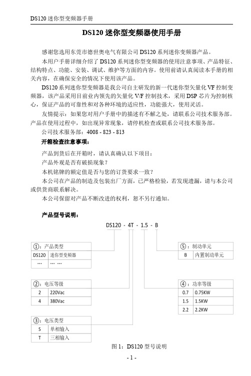
起动频率起动、直流制动再起动 减速停机、自由停机、减速停机+直流制动 制动单元动作电压:320~750V 直流制动频率:0~300Hz; 直流制动等待时间:0~50s; 直流制动电流:0.0~100.0%; 直流制动时间:0.0~50.0s; 当电网电压变化时,能自动保持输出电压 恒定 当电网电压欠压,瞬间降频维持母线电压 标配 5 路输入 标配 1 路模拟量输入,AIN:0~10V 或 0~ 20mA 输入可选 标配 1 路多功能集电极输出 标配 1 路继电器输出 提供 RS485 通讯接口,与外界 RS485 通讯, 支持 Modbus 协议(RTU 模式)
3.变频器功率偏小
1.增大减速时间 2.外加合适的能耗制动组件 3.选用功率大一档的变频器
1.负载发生突变或异常 恒速运行
2.电网电压偏低 过电流
3.变频器功率偏小
1.检查负载或减小负载的突变 2.检查输入电源 3.选用功率大一档的变频器
1.输入电压异常
加速运行
1.检查输入电源
2.瞬间停电后,对旋转中电机实
3.通讯长时间中断
1.设置合适的波特率 2.按 STOP/RESET 键复位,寻求 服务 3.检查通讯接口配线
E.EF 外部故障 1.DI 外部故障输入端子动作 1.检查外部设备输入
输出侧缺 1.U,V,W 缺相输出 相 2.负载三相严重不对称
1.检查输出配线 2.检查电机及电缆
1.检查制动单元,更换新制动 制动单元 1.制动线路故障或制动管损坏
管 故障 2.外接制动电阻阻值偏小
2.增大制动电阻
PLC说明书

COM2(RS-485)通 讯 传 送 (Tx) 指 示灯
10
COM1(RS-232)程序输出/入通讯 口
11 铭牌
※ 电池安装:更换电池时,请在 3 分钟内完成,否则 PLC 内部资料(包含程序 12 扩展连接口
区,万年历及停电保持寄存器)有可能会消失或被破坏。
13 扩展定位孔
14 DIN 轨糟﹝35mm﹞
S0~S9, 10 点(*1)
S10~S19, 10 点, 搭配 IST 指令使用(*1) S20~S511, 492 点(*1) S512~S895, 384 点(*3)
合计 1024 点
S896~S1023, 124 点(*3)
T0~T255, 256 点
C0~C199, 16 位计数器, 200 点 C200~C254, 32 位计数器, 50 点 D0~D199, 200 点(*1) D200~D999, 800 点(*3) D2000~D4999, 3000 点(*3) D1000~D1999, 1000 点 E0~E3, F0~F3, 8 点(*1) 0~1599(1600 点) (*4) N0~N7, 8 点 P0~P255, 256 点
台 達P L C產 品 型 號 輸入電源規格
全系列扩展,包含数字输入/输出(最大输入/输出扩展点数分
輸 出點 模塊 規格 管 制條 碼及 序號
别可达 128 点)、模拟量模块(A/D,D/A 转换及温度单元)等各
程 序版 本
V1.00
类机型,满足各种应用场合。电源单元与主机分离,体积小,
安装容易。
型号
200605-22
ht tp: //w ww. del ta .c om .tw /i nd uБайду номын сангаас tr i a l a u tom a ti o n /
Fri-Jado HI 120 制冷机操作手册说明书
USER MANUALEuropean Model HI 120American Model HI 48WARNINGRead this manual before using the machine.KEEP THIS USER MANUAL FOR FUTURE USE© 2018 Fri-Jado B.V., Etten-Leur, The Netherlands.We advise you to contact your supplier for the guarantee period and conditions. Further we refer to our General Terms and Conditions for Sales and Delivery that are available upon request.The manufacturer does not accept any liability for damage or injury caused by failing to adhere to these regulations or by not observing the usual caution or care in actions, operation, maintenance or repair activities, even if not explicitly described in this manual.As a result of constant commitment to improvement, it may happen that your unit deviates in detail from what is described in this manual. For this reason, the given instructions are only a guideline for the installation, use, maintenance and repair of the unit referred to in this manual. This manual has been composed with the utmost care. The manufacturer shall, however, not be held responsible for any mistakes in this manual nor for any consequences thereof. The user is allowed to copy this manual for own use. Further all rights are reserved and nothing in this manual may be reproduced and/or made public in any way.ModificationsIn case of unauthorized modifications in or on the unit, every liability on the part of the manufacturer becomes null and void.CONTENTS1.INTRODUCTION (4)1.1General (4)1.2Identification of the unit (4)1.3Pictograms and symbols (4)1.4Safety instructions (5)1.4.1General (5)1.4.2Moving (6)1.5Hygiene (6)1.6Service and technical support (6)1.7Storage (6)1.8Disposal (6)2.DESCRIPTION OF THE UNIT (7)2.1Technical description (7)2.2Intended use (7)2.3Accessories (7)3.INSTALLATION AND FIRST USE (8)3.1Assembling the middle panes (9)3.1.1Upper pane (9)3.1.2Bottom pane (10)4.OPERATION AND USE (11)4.1Switch on (11)4.2Checking the temperature in the unit (12)4.3Checking the product temperature (12)4.4Switch off (12)5.DAILY MAINTENANCE (13)6.MALFUNCTIONS AND SERVICE (14)6.1Temperature fault (14)6.2Replacing a lamp (15)6.3Placing a price strip (15)6.4Replacing the child guard (16)6.5Replacing the mains cord (16)7.TECHNICAL SPECIFICATIONS (17)8.ACCESSORIES (18)1.INTRODUCTION1.1GeneralThis manual is intended for the user of the Hot Island (HI). The features and controls are being described, along with directions for the safest and most efficient use, in order to guarantee a long life of the unit.All pictograms, symbols and drawings in this manual apply to the Hot Island model.1.2 Identification of the unitThe identification plate can be found on the outside of the machine, and contains the following data:∙ Name of the supplier or the manufacturer ∙ Model∙ Serial number∙ Year of construction ∙ Voltage ∙ Frequency∙ Power consumption1.3 Pictograms and symbolsIn this manual, the following pictograms and symbols are used:WARNINGPossible physical injury or serious damage to the unit, if the instructions are not carefully followed .WARNINGHazardous electrical voltage .WARNINGDanger of getting injured by hot surfaces .Suggestions and recommendations to simplify indicated actions .Recycling symbol .Direction of view symbol .1.4Safety instructionsWARNINGThe top and bottom of the trays and columns at the back of the unit can be very hot.WARNINGThe maximum load on top of the unit may never exceed 50 kg (110 lbs).WARNINGThe maximum load per shelf may never exceed 35 kg (77 lbs).WARNINGThe maximum load of the drawer may never exceed 25 kg (55 lbs).WARNINGAlways use the brakes on both front wheels:1.4.1 GeneralThe user of the unit will be fully responsible for abiding the locally prevailing safety- rules and regulations.The pictograms, labels, instructions and warning signs attached to the unit, are part of the safety measures. They may never be covered or removed, and have to be clearly visible during the entire lifetime of the unit.Immediately repair or replace damaged or illegible pictograms, warnings and instructions.∙ Only pack the products in bags or containers that are suitable for this purpose.1 ∙ To ensure good contact with the heated trays, only place a single layer of products.∙ Make sure that the air slots at the front of the shelf as well as those in the middle of the unitremain free from obstructions.∙ The unit must be cleaned regularly to ensure proper functioning.∙ To avoid short-circuiting, never clean the unit using a water hose. For cleaning instructions,see section 5.∙ This device can be used by children ages 8 and up and person with no experience orknowledge of physics or people with limited physical, sensory or mental capacities, provided they are trained for and supervised in a safe manner with the use of the unit and they are aware of and understand the risks involved with operating the unit.∙ Children should be supervised to ensure that they do not play with the appliance.∙ Cleaning and maintenance of the device may not be executed by children, unless they areunder direct supervision.1The packaged material used must be heat resistant to at least 95 °C (203°F)1.4.2 MovingWhen moving the unit:∙ Before moving the unit, first switch off the mains voltage by pulling the plug from the wallsocket.∙ To avoid damage, remove the lower skirts when necessary.∙ The unit is not suited to pass ledges or obstacles higher than 10 mm (0.4 inch). ∙ Make sure that the wheels can move freely, so they never touch the power.1.5 HygieneThe quality of a fresh product always depends on hygiene.It is essential that products are packaged immediately after preparation. At that moment, the core temperature of the products should at least be 85°C (185°F).Immediately remove products in damaged packaging from the equipment. Clean all components that that have come in contact with products from damaged packaging. Refer to the cleaning instructions of section 5.1.6 Service and technical supportThe electrical schematics of your unit is included. In case of malfunctions you can contact your dealer/service agent. Make sure you have the following data available: ∙ Model.∙ Serial number.This data can be found on the identification plate.1.7 StorageIf the unit will not be used temporarily, and will be stored, follow these instructions: ∙ Clean the unit thoroughly.∙ Wrap the unit from getting dusty.∙ Store the unit in a dry, non-condensing environment.1.8 DisposalDispose of the machine, any components or lubricants removed from it safely in accordance with all local and national safety and environment requirements.2. DESCRIPTION OF THE UNIT2.1 Technical descriptionThe unit uses convection heat. The plating of the unit is made of stainless or coated steel and shatter-resistant clear side glass.2.2 Intended useThe HI has been designed to maintain products at a minimum temperature at 65°C (150°F). Any other use will not be regarded as intended use.The manufacturer accepts no liability whatsoever for loss or injury caused by failing to strictly adhere to the safety guidelines and instructions in this manual or due to carelessness during installation, use, maintenance and repair of the unit referred to in this manual and any of its accessories.Use the unit in perfect technical condition only.2.3 AccessoriesYour unit contains the following standard accessories:User manual.3. INSTALLATION AND FIRST USEAll packing materials used for this unit are suited for recycling.contact the transporter within fifteen working days after receiving the goods.1. Remove all packaging materials from the unit.2. Remove the protective foil from the plateaus and sides.3. Remove all temporary tape4. Before starting to use the unit, clean the inside with a damp cloth.5. Avoid excessive use of water on the shelves. Make sure no water goes into the airslots.6. Clean the side, top and middle glass both inside and out. Avoid scratches on all plasticand varnished parts, do NOT use aggressive detergents.7. In case the panes for the middle are packed separately, refer to paragraph 3.1 forinstallation instructions.3.1 Assembling the middle panes3.1.1 Upper paneNote:Follow the procedure in reverse order for removing the upper pane. Always be sure the glass cannot fall during installation by either making use of suction cups or supporting it from both sides.3.1.2 Bottom paneNote:Follow the procedure in reverse order for removing the bottom pane. Always be sure the glass cannot fall during installation by either making use of suction cups or supporting it from both sides.4. OPERATION AND USE4.1 Switch onNote: The heating and lighting cannot be switched separately.4.2 Checking the temperature in the unit4.3 Checking the product temperature4.4 Switch off5. DAILY MAINTENANCE6. MALFUNCTIONS AND SERVICE 6.1 Temperature fault6.2 Replacing a lamp6.3 Placing a price strip6.4Replacing the child guard6.5Replacing the mains cordWARNINGHazardous electrical voltage.If the mains cord is damaged, it must be replaced by the manufacturer, his service agent or a similarly qualified person in order to avoid hazards.7. TECHNICAL SPECIFICATIONSConsult the identification plate to get the proper specifications of the unit. Theelectrical data may vary from country to countryEuropean ModelAmerican ModelNote 1:Unit supplied with 3 phase cord and plug. Single phase to be converted in the field. Required plug NEMA6-30P and cable 12 AWG.8. ACCESSORIESFor the HI the following accessories are available: ∙Bumper Set *∙Cross-selling basket* Note: standard on American Models.NotesFri-Jado B.V.Oude Kerkstraat 24878 AA Etten-LeurNederlandTel: +31 (0) 76 50 85 400 Fax: +31 (0) 76 50 85 444。
H12WD系列电路保护器说明书
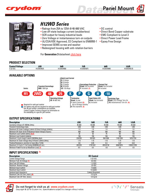
H12WD Series• Ratings from 25A to 125A @ 48-660 VAC • Low off-state leakage current (snubberless)• SCR output for heavy industrial loads• Zero Voltage or instantaneous turn-on outputs • UL/CSA/VDE Approved, CE Compliant to EN60950-1• Improved SEMS screw and washer• Redesigned housing with anti-rotation barriers For Generation 3 datasheet click here• DC control• Direct Bond Copper substrate • EMC Compliant to Level 3• Direct Power Lead Frame • Epoxy Free DesignPRODUCT SELECTIONControl Voltage 25A 50A 75A 90A 125A4-32 VDCH12WD4825H12WD4850H12WD4875H12WD4890H12WD48125AVAILABLE OPTIONSThermal PadBlank: Not Included H: IncludedSeriesTransient Overvoltage 2WD: 1200 VpkRated Load Current 25: 25 Amps 50: 50 Amps 75: 75 Amps 90: 90 Amps 125: 125 Amps Switching TypeBlank: Zero Voltage Turn-On -10: Instantaneous Turn-On Input Status LED Blank: Not Included G: Included Termination Blank: Screw F: Quick Connect (Up to 50 Amps models)K: Hex standoffs Operating Voltage 48: 48-660 VAC48H125K P G H -10Overvoltage Protection Blank: Not Included P: Included 2WD Required for valid part numberFor options only and not required for valid part number (1)(2)(3)(4)OUTPUT SPECIFICATIONS (5)125A90A75A50A25ADescriptionOperating Voltage (47-440Hz) [Vrms]48-66048-66048-66048-66048-660Transient Overvoltage [Vpk]12001200120012001200Maximum Off-State Leakage Current @ Rated Voltage [mArms] 1.0 1.0 1.0 1.0 1.0Minimum Off-State dv/dt @ Maximum Rated Voltage [V/µsec]500500500500500Maximum Load Current [Arms] (6)(3)25507590125Minimum Load Current [mArms]150150150150150Maximum 1 Cycle Surge Current (50/60Hz) [Apk]239/250597/625954/10001145/12001670/1750Maximum On-State Voltage Drop @ Rated Current [Vrms] 1.15 1.15 1.15 1.15 1.15Thermal Resistance Junction to Case (Rjc) [°C/W]0.80.450.30.270.22Maximum 1/2 Cycle I² t for Fusing (50/60Hz) [A² sec]285/2591779/16214555/41506560/597613950/12709Minimum Power Factor (at Maximum Load) (7)0.50.50.50.50.5INPUT SPECIFICATIONS (5)DescriptionDC ControlControl Voltage Range4-32 VDC Minimum Turn-On Voltage (7) 4.0 VDC Must Turn-Off Voltage 1 .0 VDC Maximum Reverse voltage -32 VDC Minimum Input Current 7 mADC Maximum Input Current 12 mADC Nominal Input ImpedanceCurrent RegulatedMaximum Turn-On Time [msec] (8)1/2 Cycle Maximum Turn-Off Time [msec]1/2 CycleNot all part number combinations are available.Contact Crydom Technical Support for information on the availability of a specific part number.*GENERAL SPECIFICATIONS (5)DescriptionParametersDielectric Strength, Input/Output/Base (50/60Hz)4000 Vrms Minimum Insulation Resistance (@ 500 V DC)109 Ohm Maximum Capacitance, Input/Output 8 pF Ambient Operating Temperature Range -40 to 80 °C Ambient Storage Temperature Range -40 to 125 °C Weight (typical) 2.6 oz (74.9 g)Housing Material 94 V-0Baseplate MaterialAluminum Input Terminal Screw Torque Range (in-lb/Nm)13-15 /1.5-1.7 Load Terminal Screw Torque Range (in-lb/Nm)18-20 / 2.0-2.2SSR Mounting Screw Torque Range (in-lb/Nm)18-20 / 2.0-2.2Humidity per IEC60068-2-7893% non-condensing Input/Load Terminal Screw Torque Range (in-lb/Nm) (3)w/”K” option 8-10 / 0.9-1.13LED Input Status Indicatorw/”G” option (green)MTBF (Mean Time Between Failures) at 40°C ambient temperature (9)11,641,553 hours (1,328 years)MTBF (Mean Time Between Failures) at 60°C ambient temperature (9)7,210,376 hours (823 years)WIRING DIAGRAMInput Current vs Input Voltage Standard Regulated DC InputI n p u t C u r r e n t (m A )DC Input VoltageEQUIVALENT CIRCUIT BLOCK DIAGRAM+DC -DC ACLimiterInput/Output Terminal Screw Thread Size #6-32 UNC / #8-32 UNCMECHANICAL SPECIFICATIONS (5)Tolerances: ±0.02 in / 0.5 mmAll dimensions are in: inches [millimeters]Screw TerminationHex Standoff Termination (“K” Option)(3)Quick Connect Termination (“F” Option ) - Up to 25 Amp (2)Quick Connect Termination (“F” Option ) - Up to 50 Amp (2)GENERAL NOTESFor additional information or specific questions, contact Crydom Technical Support.(1) O utput will self trigger between 900-1200Vpk, Min. power factor 0.7 or higher, not suitable for capacitive loads.(2) Single pair (up to 25A) Double pair* (50A model only). *Caution: User must connect to both pairs(3) Option “K” is designed and tested for use with printed circuit boards or ring/fork terminals having a thickness between 0.031 and 0.093 inches (0.79 to 2.36 mm), and loads rated up to 50 Amps. For higher load currents, the “K” standoff temperature must not exceed 105°C. For additional application assistance please contact Crydom Technical Support.(4) Instantaneous turn-on version is not recomended for capacitive loads. Use zero turn-on only. (5) All parameters at 25°C unless otherwise specified.(6) Heat sinking required, see derating curves.(7) Increase minimum voltage by 1V for operations from -20 to -40°C. (8) Turn-on time for Instantaneous turn-on versions is 0.02 msec.(9) All parameters at 50% power rating and 100% duty cycle (contact Crydom tech support for detailed report). (10) Load can be wired to either SSR output terminal 1 or 2.(11) Elective Input Status LED, “G” option.(12) Elective Overvoltage Protection, “P” option.(13) Mechanical dimensions vary from G3 models.SURGE CURRENT INFORMATIONTHERMAL DERATE INFORMATIONS u r g e C u r r e n t (A m p )Surge Duration (Secs)25 AS u r g e C u r r e n t (A m p )Surge Duration (Secs)50 A100200400300500600700900800S u r g e C u r r e n t (A m p )Surge Duration (Secs)S u r g e C u r r e n t (A m p )Surge Duration (Secs)125 AS u r g e C u r r e n t (A m p )Surge Duration (Secs)90 AAmbient Temperature (ºC)50 A0.7ºC/W1ºC/W1.5ºC/W2ºC/WAmbient Temperature (ºC)75 A0.5ºC/W0.7ºC/W1ºC/W1.5ºC/WAmbient Temperature (ºC)25 A1.5ºC/W2ºC/W3ºC/WAmbient Temperature (ºC)90 A0.5ºC/W 0.7ºC/W1ºC/W1.5ºC/WAmbient Temperature (ºC)125 A0.5ºC/W0.7ºC/W1ºC/WNon repetitive peak surge current at Tj initial 40ºC.AGENCY APPROVALSDesigned in accordance with the requirements of IEC 62314IEC 61000-4-2 : Electrostatic Discharge – Level 3 IEC 61000-4-4 : Electrically Fast Transients – Level 3 IEC 61000-4-5 : Electrical Surges – Level 3IEC 600068-2-6: Vibration 0.33mm and 0.75mm Amplitude over 10-55 Hz IEC 600068-2-27: Shock Resistance 15g/11msE116949 (25, 50, 75 and 90A)E116950 (125A)LR81689 10143 UGACCESORIESRev. 040616Part number: KS101Part number: HK4ANNEX - ENVIROMENTAL INFORMATIONThe environmental information disclosed in this annex including the EIP Pollution logo are in compliance with People’s Republic of China Electronic Industry Standard SJ/T11364 – 2006, Marking for Control of Pollution Caused by Electronic Information Products.附件 - 环保信息此附件所标示的包括电子信息产品污染图标的环保信息符合中华人民共和国电子行业标准 SJ/T11364 - 2006,电子信息产品污染控制标识要求。
QBZ-80、120、200(N)智能说明书
第一节 开始工作前.....................................................................................................................................3
第二章 个人安全.............................................................................................................................................. 5
第六章 技术数据............................................................................................................................................ 23
第一节 储存................................................................................................................................................10 第二节 运输................................................................................................................................................10
警告!9#线严禁接地
真善美包缝机1200d选配件中文说明书

1200D选购配件 使用说明书橡筋打褶压脚(C)和橡筋附件橡筋打褶压脚不仅用于没有橡筋的较硬布料,更适合用于制作你自己的饰带。
三个附件(7.5mm、10mm、13mm)分别用来将扁平的橡筋直接缝纫在布料上。
调节螺丝来控制加在打褶用的橡筋上的压力。
安装橡筋打褶压脚根据橡筋的宽度选用合适的橡筋附件。
拷边机以三线或四线快速地将橡筋缝纫在布料上。
1. 选择缝纫程序:3线宽或4线。
穿线,并按机器上或说明书的说明设置机器。
线迹宽度调到最宽。
装上橡筋打褶压脚。
2. 将橡筋附件“A”安装在橡筋打褶压脚上。
参考图1。
3. 拧松调节螺丝“B”,将橡筋放入橡筋附件的槽中。
将橡筋从压脚的下面拉到压脚的后面。
拧紧螺丝“B”,设置打褶量。
参考图2。
4. 导板“C”定位,使橡筋在针板的边上,紧贴着割刀。
5. 将机针放下,插入布料。
放下压脚。
6. 用手转动手轮缝纫开始的两针。
调节橡筋附件尝试缝纫,并且检查割刀只割到布料,不割到橡筋。
以中速缝纫。
参考图3 。
注意:如果你使用橡筋蕾丝,将蕾丝的扇贝花边插到橡筋附件的左边。
高效智能,导布器正好折出6mm的边。
同时它还卷边,并缝上放在下面的蕾丝或边饰。
和绷缝压脚(M)一起使用。
用绷缝压脚生成蕾丝边的卷边 绷缝线迹是专业的卷边方法。
蕾丝导布器折叠出6mm的边。
然后有效地在折边上缝纫绷缝线迹。
缝纫扁平的卷边时这个卷边方法最合适。
蕾丝送入后线迹就缝纫上去。
1. 选择缝纫程序:三针绷缝,绷缝宽或绷缝。
按机器上的提示设置机器并穿线。
装上绷缝压脚。
2. 折出或用手指压出大约5cm布料,下面6mm形成卷边。
3. 导布器装在压脚前,先将折边放入H-2导布器。
参考图1。
4. 布料放在压脚下面,机针插入布料。
放下压脚。
将导布器H-2卡在压脚上。
参考图2。
5. 用手转动手轮缝纫开始的两针。
左手握住布料,右手折出卷边,并继续缝纫。
布料要均匀地导入。
参考图3。
均匀的边。
只要简单的将布料插入导布器,导布器自动折出并生成2.5cm的边。
蓝光主板电梯通用图

门电机U V WJ10-5J10-6AC1AC23637BL2000-CZB门电机U V WJ9-2J9-3AC1AC22627BL2000-CZB副 门 门 机主 门 门 机(02M)(02M)(02M)(02M)AC1AC2开门限位关门限位公共端关门信号开门信号公共端AC1AC2开门限位关门限位公共端关门信号开门信号公共端696862646362门机控制器门机控制器001.001(8)(9)(7)(5)(6)(4)(1)(2)(3)(8)(9)(7)(5)(6)(4)(1)(2)(3)设计审核注明SHEET 08 OF 14G20系列微机控制电梯----门机控制回路苏州巨立电梯有限公司日 期08/03/01G20系列电梯通用图版本8.01洪铜徽页 码随行通讯电缆呼梯通讯电缆GC--1引脚符号位置1234524T GND1C+C-(E)04T 04T 04U 04U屏蔽随行电缆GC--2引脚符号位置12345001537172678910826211121363U1V1W1N U2V2W2序号符号1234567电源端子位置01G 01G 01G 01B 01T 01T 01T20018706小端子台序号符号1111130416181021253B1B2限位封线门锁封线安全封线检修封线电锁封线对讲电源08123456*789101112131415161718192021备用001抱闸限速器#1#2#3#4TB1TB204F 04G 04O 04P 04H 04J 04K 04M 04M 03S 03G 03S03B03P 04G 04F04W11G 11G 03P 03M 03H03H 04K 11K 11K 11K 646869B1B2#511K04L 04M 04N11G 11G 9799消防联动并联/群控CB-GND1CB+04O 04O04W04W 04W223404Q2324252627注:1)带△的信号有紧急运行操作功能时接8910410302W 02O Y 型同步曳04X28与001与001引机时接层线141003K 03Q 29302)*7--如无盘手轮开关,请将12与14短接小端子台序号符号TB2329004T与001接抱闸1011107A 107B 02Q 02Q31WK104X检测开关3)用Y 型曳引机时注意调试结束后拆除WK1、WK2之间的短接线。
SM0主控制器模块使用说明书(PDF精品)
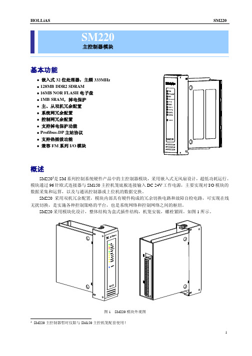
主控制器模块基本功能Array∙嵌入式32位处理器,主频333MHz∙128MB DDR2SDRAM∙16MB NOR FLASH电子盘∙1MB SRAM,掉电保护∙主、从双机冗余配置∙系统网冗余配置∙控制网冗余配置∙支持掉电保护功能∙Profibus-DP主站协议∙支持热插拔功能∙兼容FM系列I/O模块概述SM2201是SM系列控制系统硬件产品中的主控制器模块,采用嵌入式无风扇设计,超低功耗运行。
模块通过96针欧式连接器与SM150主控机笼底板连接输入DC24V工作电源,主要实现对I/O模块的数据采集和运算,以及与通讯控制器或上位机的数据交换。
SM220采用双机冗余配置,模块内部具有硬件构成的冗余切换电路和故障自检电路,可实现在线无扰切换,是实施各种控制策略的平台,也是系统网络和控制网络之间的枢纽。
1SM220主控制器暂时仅限与SM150主控机笼配套使用!原理概述SM220主控制器模块是现场控制站内的核心设备,SM220模块的硬件原理框图如图2所示。
SM220模块提供冗余工业以太网接口,把现场控制站的所有数据上传到系统服务器,同时,接收工程师/操作员站的组态指令。
SM220模块提供具备冗余Profibus-DP总线接口,实现对现场控制站内I/O模块的数据采集、处理、运算及交换。
静态存储器(SRAM)用于掉电保护电路,保存实时数据。
SM220电源模块通过96针欧式连接器引入DC24V工作电源用于给整个模块供电。
使用说明状态指示灯SM220模块上电后,其面板上的10个LED状态指示灯显示当前的工作和通讯状态。
具体状态及含义如表1所示。
表1控制器指示灯定义符号颜色定义说明RUN绿快闪注1正常运行灭停止运行STANDBY黄亮主控单元为从(双机)快闪注1主控单元为单机灭主控单元为主ERROR红亮主控单元运行错误(也表示初始上电正常)灭主控单元正常运行PROJECT绿亮主控有工程快闪注1工程下装或备份注2灭主控没有工程SYNC黄亮同步通路正常快闪注1同步数据正常灭同步通路故障(单主控)RNET黄亮双机冗余网链接正常闪注1双机冗余网链接正常并处于数据交换灭双机冗余网故障SNET1黄亮系统网1链接正常闪注1系统网1链接正常并处于数据交换灭系统网1故障SNET2黄亮系统网2链接正常闪注1系统网2链接正常并处于数据交换灭系统网2故障CNETA注3黄亮主机控制网A正常且处于侦听状态快闪注1主机控制网A正常且处于工作状态慢闪注1从机控制网A正常灭主机或从机控制网A故障CNETB注3黄亮主机控制网B正常但处于侦听状态快闪注1主机控制网B正常并处于工作状态慢闪注1从机控制网B正常灭主机或从机控制网B故障注:1.“快闪”频率为亮250ms,灭250ms;“慢闪”频率为亮100ms,灭900ms;“闪”频率未定义。
MSConfigurator 说明

2008年6月销售 服务代理商会议(宁波) 年 月销售 服务代理商会议(宁波) 月销售/服务代理商会议
1. 1 产品概要
4
1 . 产品概要
1. 1 产品名称、软件编号
产品名称 MELSOFT MS Configurator 编 号
BCN-B81006-047-B
BND-1201W000-* [* :版本名称 - - * 版本名称]
启动MS Configurator.exe,出现主画面,如下图所示 如下图所示,既可从画面上方菜单栏内的“工具”中 选择所需要的目标功能,也可以从画面下方的功能栏中选择 也可以从画面下方的功能栏中选择。
主画面
工具
主画面
1.Setup 菜单 2.AssistanceFunction 3.AllAdjust 4.IndividualAdjust 文本区域 5.MeasurementFunction 1.Setup 通讯路径设定 加振信号设定 创建程序 2.AssinstanceFunction 参数设定 3.AllAdjust 整体调整 4.IndividualAdjus 陷波滤波器调整 速度环增益调整 时间常数调整 位置环增益调整 丢步调整 丢步调整类型3 5.MeasurementFunction 频率响应测定 机械频率响应测定 测定功能
1
BCN-B81006-047-B
伺服调整工具
MS Configurator概要 Configurator概要
三菱电机自动化(上海) 三菱电机自动化(上海)有限公司 CNC事业部 事业部
2008年6月销售 服务代理商会议(宁波) 年 月销售 服务代理商会议(宁波) 月销售/服务代理商会议
2
BCN-B81006-047-B
半导体传感器ADUM1201BRZ中文规格书
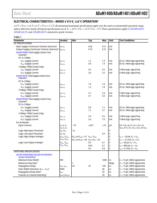
Data Sheet ADuM1400/ADuM1401/ADuM1402 Rev. L | Page 17 of 31ELECTRICAL CHARACTERISTICS—MIXED 3 V/5 V, 125°C OPERATION 13.0 V ≤ V DD1 ≤ 3.6 V ,4.5 V ≤ V DD2 ≤5.5 V; all minimum/maximum specifications apply over the entire recommended operation range, unless otherwise noted; all typical specifications are at T A = 25°C; V DD1 = 3.0 V , V DD2 = 5 V . These specifications apply to ADuM1400W , ADuM1401W , and ADuM1402W automotive grade versions. Table 7.ParameterSymbol Min Typ Max Unit Test Conditions DC SPECIFICATIONSInput Supply Current per Channel, QuiescentI DDI (Q) 0.26 0.31 mA Output Supply Current per Channel, QuiescentI DDO (Q) 0.19 0.21 mA ADuM1400W , Total Supply Current, Four Channels 2DC to 2 MbpsV DD1 Supply CurrentI DD1 (Q) 1.2 1.9 mA DC to 1 MHz logic signal freq. V DD2 Supply CurrentI DD2 (Q) 0.9 1.4 mA DC to 1 MHz logic signal freq. 10 Mbps (TRWZ Grade Only)V DD1 Supply CurrentI DD1 (10) 4.5 6.5 mA 5 MHz logic signal freq. V DD2 Supply CurrentI DD2 (10) 2.6 3.5 mA 5 MHz logic signal freq. ADuM1401W , Total Supply Current, Four Channels 2DC to 2 MbpsV DD1 Supply CurrentI DD1 (Q) 1.0 1.6 mA DC to 1 MHz logic signal freq. V DD2 Supply CurrentI DD2 (Q) 1.2 1.8 mA DC to 1 MHz logic signal freq. 10 Mbps (TRWZ Grade Only)V DD1 Supply CurrentI DD1 (10) 3.7 5.4 mA 5 MHz logic signal freq. V DD2 Supply CurrentI DD2 (10) 4.1 5.0 mA 5 MHz logic signal freq. ADuM1402W , Total Supply Current, FourChannels 2DC to 2 MbpsV DD1 Supply CurrentI DD1 (Q) 0.9 1.5 mA DC to 1 MHz logic signal freq. V DD2 Supply CurrentI DD2 (Q) 1.5 2.1 mA DC to 1 MHz logic signal freq. 10 Mbps (TRWZ Grade Only)V DD1 Supply CurrentI DD1 (10) 3.0 4.2 mA 5 MHz logic signal freq. V DD2 Supply CurrentI DD2 (10) 5.6 7.0 mA 5 MHz logic signal freq. For All ModelsInput CurrentsI IA , I IB , I IC , I ID , I E1, I E2 −10 +0.01+10µA 0 V ≤ V IA , V IB , V IC , V ID ≤ V DD1 or V DD2, 0 V ≤ V E1, V E2 ≤ V DD1 or V DD2 Logic High Input ThresholdV IH , V EH 1.6 V Logic Low Input ThresholdV IL , V EL 0.4 V Logic High Output VoltagesV OAH , V OBH , V OCH , V ODH (V DD1 or V DD2) − 0.1 V DD1, V DD2 V I Ox = −20 µA, V Ix = V IxH (V DD1 or V DD2) − 0.4V DD1, V DD2 − 0.2 V I Ox = −3.2 mA, V Ix = V IxH Logic Low Output Voltages V OAL , V OBL ,V OCL , V ODL 0.0 0.1 V I Ox = 20 µA, V Ix = V IxL 0.04 0.1 VI Ox = 400 µA, V Ix = V IxL0.2 0.4 V I Ox = 3.2 mA, V Ix = V IxLSWITCHING SPECIFICATIONSADuM1400WSRWZ /ADuM1401WSRWZ / ADuM1402WSRWZMinimum Pulse Width 3PW 1000 ns C L = 15 pF, CMOS signal levels Maximum Data Rate 41 Mbps C L = 15 pF, CMOS signal levels Propagation Delay 5t PHL , t PLH 50 70 100 ns C L = 15 pF, CMOS signal levels Pulse Width Distortion, |t PLH − t PHL |5PWD 40 ns C L = 15 pF, CMOS signal levels Propagation Delay Skew 6t PSK50 ns C L = 15 pF, CMOS signal levelsChannel-to-Channel Matching 7 t PSKCD /t PSKOD 50 ns C L = 15 pF, CMOS signal levelsData SheetADuM1400/ADuM1401/ADuM1402 Rev. L | Page 19 of 31PACKAGE CHARACTERISTICS Table 8.ParameterSymbol Min Typ Max Unit Test Conditions Resistance (Input to Output)1R I-O 1012 Ω Capacitance (Input to Output)1C I-O 2.2 pF f = 1 MHz Input Capacitance 2C I 4.0 pF IC Junction to Case Thermal Resistance, Side 1θJCI 33 °C/W Thermocouple located at center of package underside IC Junction to Case Thermal Resistance, Side 2θJCO 28 °C/W 1 Device is considered a 2-terminal device; Pin 1, Pin 2, Pin 3, Pin 4, Pin 5, Pin 6, Pin 7, and Pin 8 are shorted together and Pin 9, Pin 10, Pin 11, Pin 12, Pin 13, Pin 14, Pin 15, and Pin 16 are shorted together.2 Input capacitance is from any input data pin to ground.REGULATORY INFORMATIONThe ADuM1400/ADuM1401/ADuM1402 are approved by the organizations listed in Table 9. Refer to Table 14 and the Insulation Lifetime section for details regarding recommended maximum working voltages for specific cross-isolation waveforms and insulation levels. Table 9.ULCSA VDE CQC TÜV Recognized Under UL 1577 Component RecognitionProgram 1 Approved under CSA Component Acceptance Notice 5A Certified according to DIN V VDE V 0884-10 (VDE V 0884-10):2006-122 Approved under CQC11-471543-2012 Approved according to IEC 61010-1:2001 (2nd Edition), EN 61010-1:2001 (2nd Edition),UL 61010-1:2004, andCSA C22.2.61010.1:2005Single Protection, 2500 V rms Isolation Voltage Basic insulation per CSA 60950-1-03 and IEC 60950-1, 780 V rms (1103 V peak) maximumworking voltageReinforced insulation, 560 V peak Basic Insulation per GB4943.1-2011, 415 V rms (588 V peak) maximum working voltage, tropical climate, altitude ≤ 5000 m Reinforced insulation, 400 V rmsmaximum working voltage Reinforced insulation per CSA 60950-1-03 andIEC 60950-1, 390 V rms(551 V peak) maximumworking voltageFile E214100 File 205078 File 2471900-4880-0001File CQC14001114900 Certificate U8V 05 06 56232 002 1 In accordance with UL 1577, each ADuM1400/ADuM1401/ADuM1402 is proof tested by applying an insulation test voltage ≥3000 V rms for 1 sec (current leakage detection limit = 5 µA).2 In accordance with DIN V VDE V 0884-10, each ADuM1400/ADuM1401/ADuM1402 is proof tested by applying an insulation test voltage ≥1050 V peak for 1 sec (partial discharge detection limit = 5 pC). The asterisk (*) marking branded on the component designates DIN V VDE V 0884-10 approval.INSULATION AND SAFETY RELATED SPECIFICATIONSTable 10.ParameterSymbol Value Unit Conditions Rated Dielectric Insulation Voltage2500 V rms 1-minute duration Minimum External Air Gap (Clearance)L(I01) 7.8 min mm Measured from input terminals to output terminals, shortest distance through air Minimum External Tracking (Creepage)L(I02) 7.8 min mm Measured from input terminals to output terminals, shortest distance path along body Minimum Clearance in the Plane of the PrintedCircuit Board (PCB Clearance)L(PCB) 8.3 min mm Measured from input terminals to output terminals, shortest distance through air, and line of sight, in the PCB mounting plane Minimum Internal Gap (Internal Clearance)0.017 min mm Insulation distance through insulation Tracking Resistance (Comparative Tracking Index)CTI>400V DIN IEC 112/VDE 0303 Part 1 Isolation Group II Material Group (DIN VDE 0110, 1/89, Table 1)Source Content uid Manufacturer Part Numbe『ADUM 1201 B RZ AD U M1201B R ZRohs Code Part Life Cycle Code (')Y es A c t i v ePackage Description Pin CountS OP, S OP8,.25 8ECCN Code HTS CodeEAR99 854239 00 01Add玩ional Feature lnte白白IC TypeA L SO OP E RAT E S AT SV I NT ERFACE C I RC U I T NO M I N A L S U P P L YLength Moisture Sensttivity Level 4.9口1mOperating Temperature-Max: Operating Temp e rature-Min 105。
D1201W使用说明书SM
DW-12.5/3.1-25.2 型合成气压缩机D1201W. SM重庆气体压缩机厂有限责任公司DW-12.5/3.1-25.2型氮气压缩机严格按照 JB/T9105《大型往复活塞 压缩机技术条件》进行设计、制造和检验。
尽管如此,不正确的操作和维护可能引起严重的安全事故。
诸如压缩机损坏、设备爆炸。
危及操作人员生命等务必详细阅读并理解本说明书以下内容。
1. 概述DW-12.5/3.1-25.2型氮气压缩机是专门为河南京宝新奥新能源有限公司焦炉气制取LNG 9.5 x 10⁷Nm 3/年项目使用 DW-12.5/3.1-25.2型氮气压缩机(工厂代号 D1201W )其工作流程 如下:来自系统的氮气(压力0.31MPaG 温度w 8.43C )经进口截止阀、 入口过滤器将其水滴、尘埃等污物过滤后进入I 级进气缓冲器进入压缩 机I 级气缸,经I 、H 级压缩后(压力 2.52MPaG 温度w 135C ),经冷 却、分离后由出口截止阀去用户系统。
本机为对称平衡型(D 型),两列二级水冷。
从电机端看,1级列 在机身的左侧,H 级列在机身的右侧。
驱动机为增安型三相异步电机,通过刚性联轴器与压缩机曲轴相连。
从电机端看,电机逆时针旋转编制校对审核批准 日期 旧底图总号日期450 Kw590 r/mi n (从轴伸端看逆时针旋转)2. 压缩机技术规格2.1压缩机主要技术参数 型号 DW-12.5/3.1-25.2 型 型 式 两列对称平衡型水冷往复活塞式压缩介质氮气 压缩级数2级 输气量 12.5 m 3/min (I 级吸入状态)I 级进气压力 0.31MPaGI 级进气温度< 8.43C H 级排气压力2.52MpaG H 级排气温度< 135C 活塞仃程0.18m 曲轴转速590 rpm 轴功率410Kw 气缸直径① 410/① 260 循环冷却水耗量< 50 m 3/h 润滑油耗量< 250 g/h 主机重量10000Kg 主机外型尺寸(长X 宽X 高)4457x2146x12 最大部件重量8500Kg 电机 设备净重24000 Kg 2.2 电动机(主电机)电动机型号 YAX560-10增安型三相异步电机额定功率 额定转速 mm功率因数0.77额定电压10000V额定电流35.7A频率50Hz转动惯量> 102Kg-m重量8500 Kg3.压缩机的零部件3.1机身(D1201W-01 -00)该机机身为两列卧式对置机身,采用优质HT250铸件制造,以双头螺栓紧固。
迈兰奧克蓝字段参考平台说明书

©2020 Mellanox Technologies. All rights reserved.†For illustration only. Actual products may vary.Today’s network technologies drive OEMs to seek innovative, scalable and cost effective designs for dealing with the exponential growth of data. The Mellanox BlueField Reference Platform provides a multi-purpose fully-programmable hardware environment for evaluation, development and running of software solutions, reducing time-to-market and increasing product development and runtime efficiency.The reference platform delivers all the features of the BlueField Data Processing Unit (DPU) in convenient form factors, making it ideal for a range of software solutions, for the most demanding markets. Features include two 100Gb/s Ethernet or InfiniBand interfaces, a 16-core BlueField processor, up to 512GB of RDIMM DDR4 memory, two PCIe x16 slots, and an NVMe-ready midplane for SSD connectivity.BlueField Platform for Storage AppliancesToday’s fast storage technologies drive storage OEMs to seek innovative, scalable and costeffective designs for their applications. Powered by the BlueField DPU, the BlueField 2U Reference Platform offers a unique combination of on-board capabilities and NVMe-readiness, creating an ideal environment for storage appliance development.Platform Highlights• Leverages the processing power of Arm ® cores for storage applications such as All-FlashArrays using NVMe-oF, Ceph, Lustre, iSCSI/TCP offload, Flash Translation Layer, RAID/Erasure coding, data compression/decompression, and deduplication.• In high-performance storage arrays, BlueField serves as the system’s main CPU, handlingstorage controller tasks and traffic termination.• Provides up to 16 front-mounted 2.5” disk drive bays that are routed to an NVMe-readymidplane within the enclosure. The system can be configured as a storage JBOF with 16 drives using PCIe Gen 3.0 x2, or 8 drives with PCIe Gen 3.0 x4 lanes.BlueField Platform for Machine LearningThe BlueField 2U Reference Platform supports connectivity of up to 2 GPUs via its PCIe x16 Gen 3.0 interface, providing cost effective and integrative solutions for Machine Learning appliances. By utilizing RDMA and RoCE technology, the BlueField network controller data path hardware delivers low latency and high throughput with near-zero CPU cycles.The platform also offers GPUDirect ® RDMA technology, enabling the most efficient data exchange between GPUs and with the Mellanox high speed interconnect, optimizing real-time analytics and data insights.Powerful & Flexible Reference Platform for a Wide Range ofApplications Including Storage, Networking and Machine LearningDATA PROCESSOR PRODUCT BRIEF†NVIDIA ®Mellanox ®BlueField ®Reference Platform© Copyright 2020. Mellanox Technologies. All rights reserved. Mellanox, Mellanox logo, BlueField, BlueOS, ConnectX, ASAP2 - Accelerated Switching and Packet Processing, GPUDirect and Virtual Protocol Interconnect are registered trademarks of Mellanox Technologies, Ltd. PeerDirect is a trademark of Mellanox Technologies. All other trademarks are property of their respective owners.page 2BlueField Reference Platform 350 Oakmead Parkway, Suite 100, Sunnyvale, CA 94085Tel: 408-970-3400 • Fax: 52961PB Rev 1.8SupportFor information about Mellanox support packages, please contact your Mellanox Technologies sales representative or visit our Support Index page .T able 1 - Part Numbers and DescriptionsProductFamily OPNDescriptionBF1200MBE1200A-BN12U BlueField Reference Platform, BlueField E-Series, Crypto disabled. A storage controller platform with option for up to 16 SSDs. (SSDs are not included.)NVMe-Ready MidplaneA modular chassis midplane supports up to eight 2.5” SSDs, which can be duplicated to 16 SSDs. The midplane also supports hot swappable SSD cards, an I 2C switch to enable connectivity of the SMBUS from the platform Baseboard Management Controller (BMC) to each SSD, andan on-board clock generator/buffer.Software SupportThe BlueField Reference Platform comespre-installed with a UEFI-based bootloader and BlueOS, a Linux reference distribution targeted at BlueField-based embedded systems. Based on the Yocto Project Poky distribution, BlueOS is highly customizable for meeting specific Linux distribution requirements through the OpenEmbedded Build System. Yocto producesan SDK with an extremely flexible cross-build environment, ideal for building and running applications seamlessly for the Arm BlueField target system, on any x86 server running any Linux distribution. Mellanox OFED and NVMe-oF support is installed by default. The reference platform also provides a BMC running OpenBMC to manage the entire system. Note: Reference platform customers can run the Linux distribution of their choice.Enclosure Specifications –2U 19”–ATX form factor motherboard –BlueField DPU with 16 Armv8 A72 cores (64-bit)–Two internal x16 PCIe Gen3.0/4.0 expansion connectors–Dual-port ConnectX-5 Virtual Protocol Interconnect ® (VPI) interface• Ethernet: 40/50/100GbE QSFP ports • InfiniBand: FDR/EDR QSFP ports • 10/25Gb/s available with QSA28–Two PCIe risers enabling 2.5” NVMe SSD disk support • 8 x PCIe Gen3 x4 lanes • 16 x PCIe Gen3 x2 lanes –1 x 850W FRU power supply –Integrated BMC–32GB eMMC Flash memory for software–3 x 80mm fan cartridges DRAM DIMM Support–4 sockets for DRAM DIMMs –Up to 512GB total memory –NVDIMM-N Support2U Reference Platform Features1U Reference Platform FeaturesEnclosure Specifications –1U 19”–ATX form factor motherboard –BlueField DPU with 16 Armv8 A72 cores (64-bit)–One internal x16 PCIe Gen3.0 expansion connector–Dual-port ConnectX-5 Virtual Protocol Interconnect ® (VPI) interface• Ethernet: 40/50/100GbE QSFP ports • InfiniBand: FDR/EDR QSFP ports • 10/25Gb/s available with QSA28–1x 400W power supply –Integrated BMC–32GB eMMC Flash memory for software–3 x 80mm fan cartridges DRAM DIMM Support–4 sockets for DRAM DIMMs –Up to 512GB total memory –NVDIMM-N SupportFigure 1. 8 SSD Configuration (2U platform)Figure 2. 16 SSD Configuration (2U platform)†Figure 3: 2U Reference Platform。
DORNA东菱伺服基础技术手册(中)
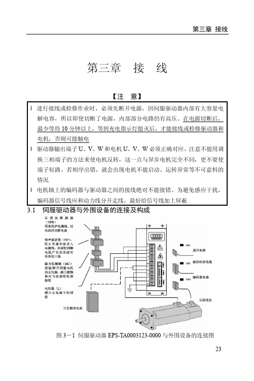
第三章 接线第三章 接 线【注 意】l 进行接线或检修作业时,必须先断开电源,因伺服驱动器内部有大容量电 解电容,所以即使切断了电源,内部部分电路仍有高压。
在电源切断后, 最少等待 10 分钟以上,等到充电指示灯熄灭后,才能接线或检修驱动器和 电机,否则可能触电l 驱动器输出端子 U、V、W 和电机 U、V、W 必须正确对应。
注意不能用调 换三相端子的方法来使电机反转,这一点与异步电机完全不同,更不要使 端子短路。
若相序出错,就会出现电机不能启动、运转异常等不可意料的 情况l 电机轴上的编码器与驱动器之间的接线绝对不能接错。
为避免感应干扰, 编码器信号线应和动力线分开走线,最好给信号线加上屏蔽3.1 伺服驱动器与外围设备的连接及构成图 3-1 伺服驱动器 EPS-TA0003123-0000 与外围设备的连接图 23第三章 接线3.2 标准接线 1. 配线(1)电源端子 TB 线径:R、S、T、U、V、W、PE 端子线径≥1.5mm² (AWG14-16),L1、L2 端子线径≥1.0mm² (AWG16-18)。
驱动器功率越大需要 TB 端子线径越粗。
接地:接地线(PE)应尽可能粗,驱动器接地线与伺服电机接地线一点接 地,接地电阻<100Ω。
端子连接必须连接牢固。
建议电源采用三相隔离变压器供电,提高电源质量和抗干扰能力。
请安装非熔断性(NFB)断路器,以便驱动器出现故障时能及时切断电源。
建议安装噪声滤波器(NF)、磁力接触器(MC)、电抗器(L),防止外部杂 波进入电源,减轻伺服电机产生的杂波对外界的干扰。
(2)通讯信号 CN1、控制信号 CN2、编码器信号 CN3 线 径 : 建 议 采用 屏 蔽 电 缆( 最 好 采用 双 绞 屏蔽 电 缆),线 径 ≥0.12mm² (AWG24-26)。
线长:电缆长度尽可能短,控制信号线 CN2 电缆不超过 5 米,编码器信号 电缆长度不超过 15 米,编码器电源和地线应分别采用 4 组以上芯线并联。
120S自动控制显示器使用说明书
120S自动控制显示器使用说明书©上海英展机电企业有限公司版权所有本产品非供交易用目录安全注意事项 (3)特点介绍 (3)第一章前/后面板规格介绍 (4)1-1前面板 (4)1-2后面板 (4)1-3按键说明 (5)1-4技术参数 (5)1-5查看程序版号 (6)第二章一般常用功能说明 (7)2-1各项设定操作程序 (7)2-2功能设定 (9)2-3错误讯息 (12)2-4内校密码设定说明 (12)第三章校正 (13)3-1荷重元安装 (13)3-2校正参数设定及校正流程 (14)3-3MODBUS校正 (16)3-4规格校正 (17)3-5一般校正 (19)3-6线性校正 (20)3-7数位校正 (22)第四章重量比较程序 (23)4-1重量比较程序之设定说明 (23)4-2重量检测之参数设定 (26)4-3计量信号输出条件 (29)4-4一般投入计量流程图(SQ-01=1) (30)4-5一般排出计量流程图(SQ-01=2) (31)4-6H I,OK,L O输出时机流程图 (32)4-7内建程序投入计量流程图(SQ-01=4) (33)4-8内建程序排出计量流程图(SQ-01=5) (33)4-9保持模式(SQ-01=6) (35)4-9-1 保持模式流程图(SO-01=6) (36)4-9-2 保持模式之Hi,OK,Lo重量比较 (37)4-10自动累加/传送 (37)第五章界面 (38)5-1串行输出/入接口(内建) (38)5-2BCD并列输出接口(OP-02) (46)5-3模拟电流输出接口(OP-03) (48)5-4外部信号输出/输入接口(OP-04,OP-05) (51)第六章维护 (56)6-1所有参数恢复为出厂设定值 (56)6-2功能参数维护 (56)6-2-1 功能设定参数恢复为出厂设定值 (56)6-2-2 清除零点补偿值及去皮值 (56)6-2-3 清除计量设定值 (57)6-2-4 显示零点电压值(mV/V) (57)6-2-5 显示跨距电压值(mV/V) (57)6-3测试模式 (58)6-3-1 7段显示器及各指示符号测试 (59)6-3-2 按键及校正开关测试 (59)6-3-3 A/D内部值显示测试 (59)6-3-4 内建RS-232 串行输出入测试 (59)6-3-5 EEPROM内存测试 (59)6-3-6 Option 适配卡测试 (59)装箱单 (61)附录一七节码字样说明 (62)附录二功能明细表 (63)附录三MODBUS DATA ADDRESS TABLE I (72)附录四MODBUS DATA ADDRESS TABLE II (73)附录五MODBUS输入与输出格式说明 (74)三包事项 (76)产品保修卡 (77)产品合格证 (77)安全注意事项当此控制器被装设于高噪声之场所时,请务必将接地线直接接于背板标示“ ”符号处如有任何因素须将后背板打开时,请务必先将电源连接线与主电源断开当自行安装选配适配卡时,请务必先断电且必须将一黄绿色之接地线固定于背板上(与另外二条接地线锁在一起)开机前请先确认所供给之电压是否在本机之接受范围内AC 100V ~ 240V操作温度为0℃~ +40℃, 储存温度为-10℃~ +55℃特点介绍120S 是一台功能强大且专为重量控制所设计之控制器,其特点如下:小型化之设计♦DIN size 面板尺寸96⨯48 mm方便收纳于控制机台内或镶嵌于控制盘面上♦前面板具泼水防护高性能A/D接口♦0.12μVD高灵敏度♦每秒120次之最高取样速度♦量测范围-0.1 ~ 4.0 mV/V灵活的校正方式♦一般2点校正♦可作5点线性校正♦可直接输入电压值mV/V,无须实际之重量负载♦可读出传感器输出之电压值mV/V,便于日后之维护可调式数字滤波器可有效的抑制现场环境所产生之振动六种重量比较模式可涵盖大部份之应用状况灵活的计量模式,可独立完成简易之系统,或连接PLC达成一复杂之系统♦具有补投料之功能♦泄料手/自动操作♦可设定批次循环次数♦重量及次数累计内建一组RS232C全双工及485通讯接口内建MODBUS (RTU) FORMAT适配卡选配部份♦OP-01 RS422/485/232串行输出/入接口♦OP-02-1 BCD并列输出接口(Open Collector输出)♦OP-02-2 BCD并列输出接口(TTL输出)♦OP-03 16 Bits Analog电流/电压输出接口(0 ~ 20 mA)♦OP-04 控制I/O(4I/4O) + Setpoint In(BCD code)♦OP-05 控制I/O(8I/8O)第一章前/后面板规格介绍∙ 6位数,红色7段显示器,字高0.63∙可作毛重/净重/累计重量/累计次数之切换显示指示符号“ ◄”置零◄: 重量置零指示动作中◄: 不稳定指示毛重◄: 毛重指示净重◄: 净重指示使用者可利用FNC- 06 ~ FNC- 09依需求设定各“ ◄”符号之指示意义,并从随机所附之贴纸中选用适合之小贴纸,贴于“ ◄”符号左边机壳上,方便操作时判读其意义。
Eaton Moeller MSC-D DOL启动器说明书

Eaton 199570Eaton Moeller® series MSC-D DOL starter, 380 V 400 V 415 V: 5.5 kW, Ir= 8 - 12 A, 230 V 50 Hz, 240 V 60 Hz, AC, Push in terminalsGeneral specificationsEaton Moeller® series MSC-D DOL starter199570MSC-D-12-M12(230V50HZ)-PI401508198271495 mm 197 mm 45 mm 0.616 kgVDE 0660 IEC/EN 60947-4-1Also suitable for motors with efficiency class IE3.Product NameCatalog Number Model CodeEANProduct Length/Depth Product Height Product Width Product Weight Certifications Catalog NotesIs the panel builder's responsibility. The specifications for the switchgear must be observed.5.5 kW230 - 415 V AC0 A230 VMeets the product standard's requirements.Is the panel builder's responsibility. The specifications for the switchgear must be observed.DIN railDoes not apply, since the entire switchgear needs to be evaluated.0 kW0 kWMeets the product standard's requirements.0 VShort-circuit release230 V Motor Starters in System xStart - brochureSave time and space thanks to the new link module PKZM0-XDM32ME Simple, flexible and safe! Distribution system for motor-starter combinationsProduct Range Catalog Switching and protecting motorsDA-DC-00004881.pdfDA-DC-00004913.pdfeaton-manual-motor-starters-motortsarter-msc-d-dol-starter-dimensions.epsETN.MSC-D-12-M12(230V50HZ)-PI.edzIL034096ZUWIN-WIN with push-in technologymsc_d_bg1_pi.dwgmsc_d_bg1_pi.stp10.11 Short-circuit ratingRated operational power at AC-3, 380/400 V, 50 Hz Rated operational voltageRated conditional short-circuit current, type 1, 480 Y/277 V Rated control supply voltage (Us) at AC, 50 Hz - min10.4 Clearances and creepage distances10.12 Electromagnetic compatibilityMounting method10.2.5 LiftingRated power at 575 V, 60 Hz, 3-phaseRated power at 460 V, 60 Hz, 3-phase10.2.3.1 Verification of thermal stability of enclosures Rated control supply voltage (Us) at DC - minFitted with:Number of pilot lightsRated control supply voltage (Us) at AC, 50 Hz - max Coordination type BrochuresCatalogsDeclarations of conformity DrawingseCAD modelInstallation instructions Installation videosmCAD model110.8 Connections for external conductorsIs the panel builder's responsibility.Coordination class (IEC 60947-4-3)Class 1Rated conditional short-circuit current, type 1, 600 Y/347 V0 APower consumption, sealing, 50 Hz1.4 W, Dual-frequency coil in a cold state and 1.0 x Us, at 50 HzAmbient operating temperature - max55 °CRated operational power at AC-3, 220/230 V, 50 Hz3 kWConnection to SmartWire-DTNoNumber of command positionsElectrical connection type of main circuitSpring clamp connectionElectrical connection type for auxiliary- and control-current circuit Spring clamp connectionRated control supply voltage (Us) at DC - max0 V10.9.3 Impulse withstand voltageIs the panel builder's responsibility.Ambient operating temperature - min-25 °C10.6 Incorporation of switching devices and componentsDoes not apply, since the entire switchgear needs to be evaluated.10.5 Protection against electric shockDoes not apply, since the entire switchgear needs to be evaluated.ClassCLASS 10 A10.13 Mechanical functionThe device meets the requirements, provided the information in the instruction leaflet (IL) is observed.10.2.6 Mechanical impactDoes not apply, since the entire switchgear needs to be evaluated.10.9.4 Testing of enclosures made of insulating materialIs the panel builder's responsibility.10.3 Degree of protection of assembliesDoes not apply, since the entire switchgear needs to be evaluated.Actuating voltage230 V 50 Hz240 V 60 HzVoltage typeACOverload release current setting - min8 ARated operational current (Ie)11.3 ASuitable forAlso motors with efficiency class IE3Number of auxiliary contacts (normally closed contacts)Rated conditional short-circuit current (Iq), type 2, 380 V, 400 V, 415 V50000 APower consumption1.4 W10.2.3.2 Verification of resistance of insulating materials to normal heatMeets the product standard's requirements.10.2.3.3 Resist. of insul. mat. to abnormal heat/fire by internal elect. effectsMeets the product standard's requirements.Overload release current setting - max12 A10.9.2 Power-frequency electric strengthIs the panel builder's responsibility.Overvoltage categoryIIIDegree of protectionIP20NEMA OtherPollution degree3Rated control supply voltage (Us) at AC, 60 Hz - min0 V10.7 Internal electrical circuits and connectionsIs the panel builder's responsibility.Rated impulse withstand voltage (Uimp)6000 V ACConnectionPush in terminals10.10 Temperature riseThe panel builder is responsible for the temperature rise calculation. Eaton will provide heat dissipation data for the devices.FunctionsTemperature compensated overload protectionRated conditional short-circuit current (Iq), type 2, 230 V0 ATypeStarter with Bi-Metal release10.2.2 Corrosion resistanceMeets the product standard's requirements.10.2.4 Resistance to ultra-violet (UV) radiationMeets the product standard's requirements.10.2.7 InscriptionsMeets the product standard's requirements.Short-circuit release (Irm) - max186 ARated control supply voltage (Us) at AC, 60 Hz - max0 VRated operational current (Ie) at AC-3, 380 V, 400 V, 415 V 12 AModelDirect starterNumber of auxiliary contacts (normally open contacts)1Eaton Corporation plc Eaton House30 Pembroke Road Dublin 4, Ireland © 2023 Eaton. All Rights Reserved. Eaton is a registered trademark.All other trademarks areproperty of their respectiveowners./socialmediaMax. 2000 m Altitude。
DC-1500~1200焊机操作手册
第 2 页 共 42 页
子上,连接工件电缆到另一端子上。
使主焊机上的“焊丝正极—焊丝负极”两位开关的设置与焊丝电缆的连接极性相一致。该开
关的设置对林肯送丝操作相对主焊机的正常控制是非常必要的。
启动焊机
按下“启动”(START)和“停止”(STOP)按钮时,进行启动或停止焊机工作。当焊机进
行工作时,位于控制面板中间的红色指示灯发亮。
c. 对冷起动而言,使用的一种工件是干净的和焊丝与电极板相连;
d. 对热起动而言,当电线连接到工作状态以前,移动应该开始;
e. 设置 NA-3 开路电压大概范围,对最初的试验状态,选择的电压设置在下面表的最低的状
态,逐渐地设置控制到 2。
这是一个大概的设置,应该注意到使用 DC-1500,OCV 要求一个理想的起动比别的理想电
对本设备上进行工作前,在保险盒或开关处关闭输入电源。
请勿接触设备带电部位。
注:查找“触发板”和“控制/故障保护电路板”的 P.C.板时,打开焊机左侧上部机箱面板,印刷
第 3 页 共 42 页
电路板上有名牌标注。 1.正常的维护 a. 风扇的马达是封闭的。 b. 在极其灰尘多的情况下,灰尘附着在空气流通道内,将使焊机发热,定期地用低压风吹掉灰
制回路还通过焊机面板上的 8A 保险向 NA—5 控制箱提供 AC115V,1000VA 控制电源。
触发电路板 G—1587—1 接受控制板送来的移相控制电压,按照移相要求发出六路触发脉冲
去触发主回路可控硅,通过改变可控硅的导通角来改变焊机输出的大小。
控制板 G—1530 是 DC—1500 最复杂的部件,他的功能是控制和保护,按功能划分,大致可
变压器线圈及整流器具有抵抗潮湿、易腐蚀环境的功能。
NBC-d系列使用说明书
NBC-d系列逆变式气体保护焊机是一种用于CO2或富氩气体保护焊接的高性能通用半自动电焊机,可使用Ф0.8 ~ Ф1.6mm直径实芯及药芯焊丝焊接低碳钢、低合金钢构件。
该系列逆变焊机具有合理的静外特性及良好的动态性能,特点如下:逆变技术可以保证焊接电压在电网电压波动及电弧长度变化的情况下高度平稳,电弧自调节能力强,焊接过程稳定。
焊接飞溅小,金属熔敷率高。
焊缝成形好,焊接变形小。
采用强脉冲引弧,引弧成功率高。
收弧时具有消球功能。
自锁功能在大规范长焊缝焊接时可降低焊工劳动强度。
送丝电路采用高稳定电源,送丝平稳。
重量轻,体积小,便于移动。
数字化控制,故障代码提示。
节能省电,使用费用低,对电网容量要求低。
该系列焊机的制造符合标准GB15579.1-2004《弧焊设备第一部分:焊接电源》。
●请务必遵守本说明书规定的注意事项,否则可能发生事故。
●输入电源的设计施工、安装场地的选择、高压气体的使用等,请按照相关标准和规定进行。
●无关人员请勿进入焊接作业场所内。
●请有专业资格的人员对焊机进行安装、检修、保养及使用。
●不得将本焊机用于焊接以外的用途(如充电、加热、管道解冻等等)。
●请勿接触带电部位。
●请专业电气人员用规定截面的铜导线将焊机接地。
●请专业电气人员用规定截面的铜导线将焊机接入电源,绝缘护套不得破损。
●在潮湿、活动受限处作业时,要确保身体与母材之间的绝缘。
●高空作业时,请使用安全网。
●请使用规定的排风设备,避免发生气体中毒和窒息等事故。
●在容器底部作业时,保护气体会沉积在周围,造成窒●请佩戴足够遮光度的保护眼镜。
弧光会引起眼部发炎,飞溅及焊渣会烫伤眼睛。
●请使用焊接用皮质保护手套、长袖衣服、帽子、护脚、围裙等保护用品,以免弧光、飞溅及焊渣灼伤、烫伤皮肤。
●焊接场所不得放置可燃物,飞溅和烫焊缝会引发火灾。
●电缆与母材要连接紧固,否则会发热酿成火灾。
●请勿在可燃性气体中焊接或在盛有可燃性物质的容器上焊接,否则会引起爆炸。
- 1、下载文档前请自行甄别文档内容的完整性,平台不提供额外的编辑、内容补充、找答案等附加服务。
- 2、"仅部分预览"的文档,不可在线预览部分如存在完整性等问题,可反馈申请退款(可完整预览的文档不适用该条件!)。
- 3、如文档侵犯您的权益,请联系客服反馈,我们会尽快为您处理(人工客服工作时间:9:00-18:30)。
DW-12.5/3.1-25.2型合成气压缩机D1201W. SM重庆气体压缩机厂有限责任公司2.压缩机技术规格2.1 压缩机主要技术参数型号DW-12.5/3.1-25.2型型式两列对称平衡型水冷往复活塞式压缩介质氮气压缩级数2级输气量12.5 m3/min(Ⅰ级吸入状态)Ⅰ级进气压力0.31MPaGⅠ级进气温度≤8.43℃Ⅱ级排气压力 2.52MpaGⅡ级排气温度≤135℃活塞行程0.18m曲轴转速590 rpm轴功率410Kw气缸直径Φ410/Φ260循环冷却水耗量≤50 m3/h润滑油耗量≤250 g/h主机重量10000Kg主机外型尺寸(长×宽×高)4457x2146x1200 mm最大部件重量8500Kg 电机设备净重24000 Kg2.2电动机(主电机)电动机型号YAX560-10增安型三相异步电机额定功率450 Kw额定转速590 r/min (从轴伸端看逆时针旋转)功率因数0.77额定电压10000V额定电流35.7A频率50Hz转动惯量>102Kg-m2重量8500 Kg3.压缩机的零部件3.1 机身(D1201W-01-00)该机机身为两列卧式对置机身,采用优质HT250铸件制造,以双头螺栓紧固。
机身流线型设计美观大方。
完全符合力学原理的加强筋布置,使整个机身具有足够的强度和刚度。
机身内有三个主轴承,轴瓦为钢背锡锑合金薄壁瓦。
轴承与轴颈的径向间隙由加工保证,安装时以便更换调整,不应以刮研、修配来实现,磨损后不能修理,只能更换。
3.2 曲轴(D1201W-02-00)曲轴采用45 优质碳素钢锻制,精心机械加工而成。
曲拐颈,主轴颈光洁度很高,使用维护中应严防磕碰划伤。
曲轴装于机身的轴承孔内,装有抛油圈的一端通过刚性联轴器与电动机相连,从主轴颈至曲柄销钻有油孔,以便通油润滑主轴颈、曲柄销、连杆小头及十字头滑道。
3.3 连杆(D1201-03-00)连杆由连杆体及连杆盖组成。
采用45优质碳素钢锻制,精心加工。
杆身截面为圆形,杆身心步钻有通油孔。
连杆大头为对开式,大头瓦为钢背锡锑合金薄壁瓦,用连杆螺栓和螺母固定于连杆体上,连杆小头装有锡青铜衬套,内有油槽,润滑油通过曲轴、连杆体内油道进入油槽,分别润滑连杆大小头轴瓦、十字头销和十字头滑道。
3.4十字头(D1201W-04-00)十字头体用优质45碳素钢精密铸造,精心加工。
设有可拆卸的钢背滑履,摩擦面浇有锡锑轴承合金,具有良好的摩擦性能。
十字头体端部有定位孔,孔底放有调整垫,以调整活塞止点间隙,孔内插有键槽,以活塞杆上的平键防止活塞转动。
十字头与活塞杆通过螺纹连接,然后用螺母背紧。
在紧固螺母时,应力量均匀,并有足够的预紧力,使活塞运动时,不得有任何松动。
3.5 气缸本机共两个气缸,Ⅰ、Ⅱ级气缸各一个,均为双作用,气缸由缸座、缸体及缸盖组成,通过螺栓将气缸体与缸座连接。
气体均由缸体上部进入,下部排除(习称上进下排)。
Ⅰ、Ⅱ级气缸用耐蚀合金铸铁制造,缸体为三层壁,夹套内可通水冷却。
各级气缸均设有注油孔,可向缸内注油,用以润滑缸壁与活塞、支承环、活塞环的摩擦表面。
气缸盖侧设有弹性支承,支承底板有调节螺钉,借以调整气缸水平,并支承气缸重量。
特别提示:气缸是压缩机的核心,是组成压缩容积的关键部件,活塞装入气缸后应检查在缸内的止点间隙,各缸止点间隙如下表:3.6 活塞在曲柄连杆机构的作用下,活塞用以改变气缸工作容积,提高气体压力。
活塞组件由活塞杆、活塞体、活塞环、支承环组成。
Ⅰ、Ⅱ级活塞用耐蚀合金铸铁制造。
活塞环、支撑环用优质碳纤维增强聚四氟乙烯(CFRP)材料制成。
各级活塞杆均用优质42CrMoE锻件制造,与填料摩擦段表面表面淬火处理,具有优良的机械性能和耐磨性。
3.7 填料填料用以控制被压缩介质向气缸外泄露。
填料密封元件均采用碳纤维增强聚四氟乙烯(CFRP)材料制造,三、六瓣平面结构。
填料压盖法兰上设有漏气回收接头,可将泄露气体回收;设有冷却水进出口,可向填料盒通水冷却;设有注油孔,可向填料盒内注油以润滑密封环与活塞杆摩擦表面。
3.8 刮油器刮油器用以刮除活塞杆上润滑油,阻止润滑油进入压缩气缸。
刮油器由由一个阻气环,三个刮油环和一组密封环组成,刮油环的材料为优质灰铸铁制造,密封环由F-4塑料制成,刮油环的作用是刮去活塞杆上的油,以免机身内的润滑油窜入气缸,刮油环内侧具有尖锐的刀口,但无毛刺,外侧由弹簧箍紧以保持与活塞杆密切的配合,弹簧的箍紧程度直接与密封环的寿命和漏气的多少有关。
两个刮油圈组成,刮油圈的材料为铸铜合金,刮油圈内侧具有尖锐的刃口,但并无毛刺,外侧由位伸弹簧压住以保持与活塞杆能密切贴合。
3.9 气阀本机各级气阀均采用环状气垫阀,气阀由阀座、限制器、阀片、弹簧及联接螺栓螺母组成。
各级气阀的阀座、限制器均用不锈钢锻件制造,阀片均用不锈钢制造,气阀弹簧均采用进口不锈钢丝制造。
同一气阀的弹簧尽可能挑选高度尺寸一致的弹簧。
阀座和阀片的密封面加工精度较高, 拆装时应注意, 不得损伤其密封面。
气阀与气缸接合处,靠垫圈密封。
特别提示:吸排气阀装入气缸时应注意方向,以免吸排气阀装反。
同时,气阀为主要易损件,压缩机运行时应随时注意监控,一旦气阀损坏,应及时更换,以免影响气量及级间压力,确保设备正常、安全运行。
3.10 安全阀Ⅰ、Ⅱ级排气管路上分别设有全启式弹簧式安全阀,以保证压缩机及系统能够安全运行。
安全阀阀头以弹簧压在安全阀座上,安全阀之开启压力可用弹簧调节。
安全阀的开启压力可以根据其使用压力,由制造厂家调定或由安全阀检定部门调定。
安全阀的安装、使用和维修等应按有关规程、规范、标准等进行。
下表为各级安全阀工作压力。
安全阀工作压力特别提示:安全阀确保系统安全工作的重要环节,安全阀失灵失效后果不堪设想,因此,安全阀的使用除必须按技术监督部门规定定期校验外,严禁随意拆装及调整。
安全阀进出口管路上严禁设置阀门。
4.压缩机的辅机和管路4.1压缩机辅机压缩机辅机包括缓冲器、冷却器和分离器。
4.1.1缓冲器:缓冲器是安装在气体管道上离气缸较近的容器。
主要作用是稳定气体压力,降低管道内气流脉动。
本机各级均设有进排气缓冲器。
Ⅰ、Ⅱ级进气缓冲器为立式圆筒形容器,直接和气缸相连,气体从缓冲器上部进口进入,底部出口排出;Ⅰ、Ⅱ级排气缓冲器为立式圆筒形容器,气体从缓冲器顶部进口进入,下部出口排出;Ⅰ、Ⅱ级进气分离缓冲器为立式圆筒形容器,气体从容器上部进口管转折进入,在容器内作旋转运动,分离掉气体中的液滴和尘埃,然后再转折向上从顶部出口排出。
各级进、排气缓冲器用碳素钢(Q345R)制造。
4.1.2冷却器:用以冷却压缩后的高温气体,保证进入下一级气缸的气体温度在规定的范围内。
本机设有Ⅰ、Ⅱ级冷却器,Ⅰ级冷却器为管壳式冷却器卧式结构,Ⅱ级冷却器为三程管壳式冷却器卧式结构。
4.1.3 分离器:用以分离气体中的油、水等杂质及其它污物。
本机各级均设有分离器,均为立式圆筒形容器结构。
分离器利用离心和重力分离的原理,气体从筒体上部进口管切向进入,烟筒壁旋转,在离心力的作用下,液滴被甩到容器壁面上,并沿壁面降落。
沉积在容器底部,从排污口排出,气流以较低的速度上升,从中心排出管排出。
缓冲器、分离器、冷却器均属压力容器,严格按照GB150、GB151及《压力容器安全技术监察规程》等有关规程、规范和标准设计制造,其安装、使用、维修等均应遵循有关规程、规范和标准。
4.2 压缩机管路系统压缩机管路包括气体管路、水管路、排污管路、循环油管路、注油管路和仪表管路等。
4.2.1 气体管路:本机备有自Ⅰ级进口阀门至Ⅱ级出口阀门的全部管道阀门和管路附件,还包括Ⅰ回Ⅰ、Ⅰ放空、Ⅱ回Ⅰ、Ⅱ放空等管道、阀门及附件。
Ⅰ级进口阀门前、Ⅱ级出口阀门后的管道、阀门及附件由用户自行配备,放空阀门后由用户自行接管至安全场所。
各级排气管路上均设有安全阀,以保证压缩机及系统能够安全运行。
安全阀的安装、使用、检修等应按有关规程、规范和标准进行。
安全阀以后的管道由用户自行接管至安全场所。
4.2.2 水管路来自上水总管的冷却水,经进口截止阀进入单机冷却水进水总管,然后分七支分别到Ⅰ、Ⅱ级冷却器,Ⅰ、Ⅱ级气缸及填料和稀油站。
然后以各级冷却器和气缸、填料出水管回检水槽回水总管,而形成封闭循环冷却,检水槽上装有视水器,可观察冷却水流动情况,还装有温度计可通过回水阀门调节水量,控制水温。
进水压力、温度检测点设在进水闸阀后的进水总管上,进水压力应≥0.35MPa,不得<0.35MPa,温度应≤30℃。
当机器停用是,应将放水阀门打开把管路中所有的积水放掉,以免管路锈蚀或冬季冻裂。
4.2.3 排污管路本机Ⅰ、Ⅱ级分离器排污均集中与排污总管,集中操作,排污总管使用单位可置于楼台适当位置。
Ⅰ级进气缓冲分离器排污,因其工作压力为0.936MPa,不便集中于楼台上操作,故就地设有排污阀门。
排污总管后、Ⅰ级进气缓冲分离器排污阀门后由使用单位自行接管至排污沟或回收或引至其它安全场所,4.2.4 循环油管路来自稀油站的压力油流经主轴承、连杆轴承、小头衬套、十字头滑道等运动机构摩擦部位,汇于机身,经回油总管回至稀油站。
循环油是洁净的机械油,一般使用GB443规定的N68号机械油,其性能应符合牌号的规定,循环油压力0.35~0.4 MPa,不得低于0.3 MPa,油冷却后温度应≤42℃。
稀油站的安装、使用和维修应按制造单位的安装使用说明进行。
4.2.5 注油管路压缩机各级气缸填料采用真空式高压注油器注油润滑。
气缸润滑油采用SY1216《压缩机油》规定的S19号压缩机油。
4.2.6 仪表管路本机配有检测压力、温度的全套仪表管道和管线。
压力管线:Ⅰ级进气压力接头设于Ⅰ级进气缓冲分离器上,Ⅰ、Ⅱ级排气压力接头设在相应级分离器上。
循环油过滤前后压力接头设在稀油站上,冷却水进水压力检测点设在进水截止阀后管道上。
各点均通过导压力管线引至操作台上的压力表,集中显示。
进入DCS系统的压力进压力表前通过三通接头引入压力变送器,压力变送器装于操作台内。
导压管接通后应清除内部污物,保证管子畅通。
温度管线:Ⅰ、Ⅱ级进气温度检测点设在各级进气缓冲器上,Ⅰ、Ⅱ级排气温度检测点设在各级排气缓冲器上,冷却水进水温度检测点设在进水截止阀后管道上,循环油冷却前后温度检测点设在稀油站上,主轴承温度检测点设在轴承盖上,电机定子温度检测点设在电机定子上,各接点均用铂热电阻引至仪表柜集中数字显示,引入DCS系统温度采用双支铂热电阻。
4.3 压缩机自动控制与保护为保证压缩机安全运行,本机设有全套监测保护系统,当压缩机处于危险工况时,能自动发出声、光等报警信号,或者自动停车。
本机设有如下报警信号:a. Ⅰ级进气压力过低≤0.28MPa 报警;b. 末级排气压力过高≥2.77 MPa 报警并延时停车;c. 循环油压力过低≤0.25 MPa 报警;≤0.20 MPa停车;d. 冷却水进水压力过低≤0.30 MPa 报警;≤0.20 MPa 停车;e. 各级排气温度过高≥150℃报警;f. 主轴承温度过高≥65℃报警;≥75℃停车;g. 循环油温度过高≥45℃报警;h. 电机定子温度过高≥150℃报警。
