Advances in Nitrogen Loss Leached by Precipitation from Plant Canopy
A_review_of_advanced_and_practical_lithium_battery_materials
A review of advanced and practical lithium battery materialsRotem Marom,*S.Francis Amalraj,Nicole Leifer,David Jacob and Doron AurbachReceived 3rd December 2010,Accepted 31st January 2011DOI:10.1039/c0jm04225kPresented herein is a discussion of the forefront in research and development of advanced electrode materials and electrolyte solutions for the next generation of lithium ion batteries.The main challenge of the field today is in meeting the demands necessary to make the electric vehicle fully commercially viable.This requires high energy and power densities with no compromise in safety.Three families of advanced cathode materials (the limiting factor for energy density in the Li battery systems)are discussed in detail:LiMn 1.5Ni 0.5O 4high voltage spinel compounds,Li 2MnO 3–LiMO 2high capacity composite layered compounds,and LiMPO 4,where M ¼Fe,Mn.Graphite,Si,Li x TO y ,and MO (conversion reactions)are discussed as anode materials.The electrolyte is a key component that determines the ability to use high voltage cathodes and low voltage anodes in the same system.Electrode–solution interactions and passivation phenomena on both electrodes in Li-ion batteries also play significant roles in determining stability,cycle life and safety features.This presentation is aimed at providing an overall picture of the road map necessary for the future development of advanced high energy density Li-ion batteries for EV applications.IntroductionOne of the greatest challenges of modern society is to stabilize a consistent energy supply that will meet our growing energy demands.A consideration of the facts at hand related to the energy sources on earth reveals that we are not encountering an energy crisis related to a shortage in total resources.For instancethe earth’s crust contains enough coal for the production of electricity for hundreds of years.1However the continued unbridled usage of this resource as it is currently employed may potentially bring about catastrophic climatological effects.As far as the availability of crude oil,however,it in fact appears that we are already beyond ‘peak’production.2As a result,increasing oil shortages in the near future seem inevitable.Therefore it is of critical importance to considerably decrease our use of oil for propulsion by developing effective electric vehicles (EVs).EV applications require high energy density energy storage devices that can enable a reasonable driving range betweenDepartment of Chemistry,Bar-Ilan University,Ramat-Gan,52900,Israel;Web:http://www.ch.biu.ac.il/people/aurbach.E-mail:rotem.marom@live.biu.ac.il;aurbach@mail.biu.ac.ilRotem MaromRotem Marom received her BS degree in organic chemistry (2005)and MS degree in poly-mer chemistry (2007)from Bar-Ilan University,Ramat Gan,Israel.She started a PhD in electrochemistry under the supervision of Prof.D.Aurbach in 2010.She is currently con-ducting research on a variety of lithium ion battery materials for electric vehicles,with a focus on electrolyte solutions,salts andadditives.S :Francis AmalrajFrancis Amalraj hails from Tamil Nadu,India.He received his MSc in Applied Chemistry from Anna University.He then carried out his doctoral studies at National Chemical Laboratory,Pune and obtained his PhD in Chemistry from Pune University (2008).He is currently a postdoctoral fellow in Prof.Doron Aurbach’s group at Bar-Ilan University,Israel.His current research interest focuses on the synthesis,electrochemical and transport properties of high ener-getic electrode materials for energy conversion and storage systems.Dynamic Article Links CJournal ofMaterials ChemistryCite this:DOI:10.1039/c0jm04225k /materialsFEATURE ARTICLED o w n l o a d e d b y B e i j i n g U n i v e r s i t y o f C h e m i c a l T e c h n o l o g y o n 24 F e b r u a r y 2011P u b l i s h e d o n 23 F e b r u a r y 2011 o n h t t p ://p u b s .r s c .o r g | d o i :10.1039/C 0J M 04225KView Onlinecharges and maintain acceptable speeds.3Other important requirements are high power density and acceptable safety features.The energy storage field faces a second critical chal-lenge:namely,the development of rechargeable systems for load leveling applications (e.g.storing solar and wind energy,and reducing the massive wasted electricity from conventional fossil fuel combustion plants).4Here the main requirements are a very prolonged cycle life,components (i.e.,relevant elements)abun-dant in high quantities in the earth’s crust,and environmentally friendly systems.Since it is not clear whether Li-ion battery technology can contribute significantly to this application,battery-centered solutions for this application are not discussedherein.In fact,even for electrical propulsion,the non-petroleum power source with the highest energy density is the H 2/O 2fuel cell (FC).5However,despite impressive developments in recent years in the field,there are intrinsic problems related to electrocatalysis in the FCs and the storage of hydrogen 6that will need many years of R&D to solve.Hence,for the foreseeable future,rechargeable batteries appear to be the most practically viable power source for EVs.Among the available battery technologies to date,only Li-ion batteries may possess the power and energy densities necessary for EV applications.The commonly used Li-ion batteries that power almost all portable electronic equipment today are comprised of a graphite anode and a LiCoO 2cathode (3.6V system)and can reach a practical energy density of 150W h kg À1in single cells.This battery technology is not very useful for EV application due to its limited cycle life (especially at elevated temperatures)and prob-lematic safety features (especially for large,multi-cell modules).7While there are ongoing developments in the hybrid EV field,including practical ones in which only part of the propulsion of the car is driven by an electrical motor and batteries,8the main goal of the battery community is to be able to develop full EV applications.This necessitates the development of Li-ion batteries with much higher energy densities compared to the practical state-of-the-art.The biggest challenge is that Li-ion batteries are complicated devices whose components never reach thermodynamic stability.The surface chemistry that occurs within these systems is very complicated,as described briefly below,and continues to be the main factor that determines their performance.9Nicole Leifer Nicole Leifer received a BS degree in chemistry from MIT in 1998.After teaching high school chemistry and physics for several years at Stuyvesant High School in New York City,she began work towards her PhD in solid state physics from the City University of New York Grad-uate Center.Her research con-sisted primarily of employing solid state NMR in the study of lithium ion electrode materialsand electrode surfacephenomena with Prof.Green-baum at Hunter College andProf.Grey at Stony Brook University.After completing her PhD she joined Prof.Doron Aurbach for a postdoctorate at Bar-Ilan University to continue work in lithium ion battery research.There she continues her work in using NMR to study lithium materials in addition to new forays into carbon materials’research for super-capacitor applications with a focus on enhancement of electro-chemical performance through the incorporation of carbonnanotubes.David Jacob David Jacob earned a BSc from Amravati University in 1998,an MSc from Pune University in 2000,and completed his PhD at Bar-Ilan University in 2007under the tutelage of Professor Aharon Gedanken.As part of his PhD research,he developed novel methods of synthesizing metal fluoride nano-material structures in ionic liquids.Upon finishing his PhD he joined Prof.Doron Aurbach’s lithium ionbattery group at Bar-Ilan in2007as a post-doctorate and during that time developed newformulations of electrolyte solutions for Li-ion batteries.He has a great interest in nanotechnology and as of 2011,has become the CEO of IsraZion Ltd.,a company dedicated to the manufacturing of novelnano-materials.Doron Aurbach Dr Doron Aurbach is a full Professor in the Department of Chemistry at Bar-Ilan Univer-sity (BIU)in Ramat Gan,Israel and a senate member at BIU since 1996.He chaired the chemistry department there during the years 2001–2005.He is also the chairman of the Israeli Labs Accreditation Authority.He founded the elec-trochemistry group at BIU at the end of 1985.His groupconducts research in thefollowing fields:Li ion batteries for electric vehicles and for otherportable uses (new cathodes,anodes,electrolyte solutions,elec-trodes–solution interactions,practical systems),rechargeable magnesium batteries,electronically conducting polymers,super-capacitors,engineering of new carbonaceous materials,develop-ment of devices for storage and conversion of sustainable energy (solar,wind)sensors and water desalination.The group currently collaborates with several prominent research groups in Europe and the US and with several commercial companies in Israel and abroad.He is also a fellow of the ECS and ISE as well as an associate editor of Electrochemical and Solid State Letters and the Journal of Solid State Electrochemistry.Prof.Aurbach has more than 350journals publications.D o w n l o a d e d b y B e i j i n g U n i v e r s i t y o f C h e m i c a l T e c h n o l o g y o n 24 F e b r u a r y 2011P u b l i s h e d o n 23 F e b r u a r y 2011 o n h t t p ://p u b s .r s c .o r g | d o i :10.1039/C 0J M 04225KAll electrodes,excluding 1.5V systems such as LiTiO x anodes,are surface-film controlled (SFC)systems.At the anode side,all conventional electrolyte systems can be reduced in the presence of Li ions below 1.5V,thus forming insoluble Li-ion salts that comprise a passivating surface layer of particles referred to as the solid electrolyte interphase (SEI).10The cathode side is less trivial.Alkyl carbonates can be oxidized at potentials below 4V.11These reactions are inhibited on the passivated aluminium current collectors (Al CC)and on the composite cathodes.There is a rich surface chemistry on the cathode surface as well.In their lithiated state,nucleophilic oxygen anions in the surface layer of the cathode particles attack electrophilic RO(CO)OR solvents,forming different combinations of surface components (e.g.ROCO 2Li,ROCO 2M,ROLi,ROM etc.)depending on the electrolytes used.12The polymerization of solvent molecules such as EC by cationic stimulation results in the formation of poly-carbonates.13The dissolution of transition metal cations forms surface inactive Li x MO y phases.14Their precipitation on the anode side destroys the passivation of the negative electrodes.15Red-ox reactions with solution species form inactive LiMO y with the transition metal M at a lower oxidation state.14LiMO y compounds are spontaneously delithiated in air due to reactions with CO 2.16Acid–base reactions occur in the LiPF 6solutions (trace HF,water)that are commonly used in Li-ion batteries.Finally,LiCoO 2itself has a rich surface chemistry that influences its performance:4LiCo III O 2 !Co IV O 2þCo II Co III 2O 4þ2Li 2O !4HF4LiF þ2H 2O Co III compounds oxidize alkyl carbonates;CO 2is one of the products,Co III /Co II /Co 2+dissolution.14Interestingly,this process seems to be self-limiting,as the presence of Co 2+ions in solution itself stabilizes the LiCoO 2electrodes,17However,Co metal in turn appears to deposit on the negative electrodes,destroying their passivation.Hence the performance of many types of electrodes depends on their surface chemistry.Unfortunately surface studies provide more ambiguous results than bulk studies,therefore there are still many open questions related to the surface chemistry of Li-ion battery systems.It is for these reasons that proper R&D of advanced materials for Li-ion batteries has to include bulk structural and perfor-mance studies,electrode–solution interactions,and possible reflections between the anode and cathode.These studies require the use of the most advanced electrochemical,18structural (XRD,HR microscopy),spectroscopic and surface sensitive analytical techniques (SS NMR,19FTIR,20XPS,21Raman,22X-ray based spectroscopies 23).This presentation provides a review of the forefront of the study of advanced materials—electrolyte systems,current collectors,anode materials,and finally advanced cathodes materials used in Li-ion batteries,with the emphasis on contributions from the authors’group.ExperimentalMany of the materials reviewed were studied in this laboratory,therefore the experimental details have been provided as follows.The LiMO 2compounds studied were prepared via self-combus-tion reactions (SCRs).24Li[MnNiCo]O 2and Li 2MnO 3$Li/MnNiCo]O 2materials were produced in nano-andsubmicrometric particles both produced by SCR with different annealing stages (700 C for 1hour in air,900 C or 1000 C for 22hours in air,respectively).LiMn 1.5Ni 0.5O 4spinel particles were also synthesized using SCR.Li 4T 5O 12nanoparticles were obtained from NEI Inc.,USA.Graphitic material was obtained from Superior Graphite (USA),Timcal (Switzerland),and Conoco-Philips.LiMn 0.8Fe 0.2PO 4was obtained from HPL Switzerland.Standard electrolyte solutions (alkyl carbonates/LiPF 6),ready to use,were obtained from UBE,Japan.Ionic liquids were obtained from Merck KGaA (Germany and Toyo Gosie Ltd.,(Japan)).The surface chemistry of the various electrodes was charac-terized by the following techniques:Fourier transform infrared (FTIR)spectroscopy using a Magna 860Spectrometer from Nicolet Inc.,placed in a homemade glove box purged with H 2O and CO 2(Balson Inc.air purification system)and carried out in diffuse reflectance mode;high-resolution transmission electron microscopy (HR-TEM)and scanning electron microscopy (SEM),using a JEOL-JEM-2011(200kV)and JEOL-JSM-7000F electron microscopes,respectively,both equipped with an energy dispersive X-ray microanalysis system from Oxford Inc.;X-ray photoelectron spectroscopy (XPS)using an HX Axis spectrom-eter from Kratos,Inc.(England)with monochromic Al K a (1486.6eV)X-ray beam radiation;solid state 7Li magic angle spinning (MAS)NMR performed at 194.34MHz on a Bruker Avance 500MHz spectrometer in 3.2mm rotors at spinning speeds of 18–22kHz;single pulse and rotor synchronized Hahn echo sequences were used,and the spectra were referenced to 1M LiCl at 0ppm;MicroRaman spectroscopy with a spectrometerfrom Jobin-Yvon Inc.,France.We also used M €ossbauer spec-troscopy for studying the stability of LiMPO 4compounds (conventional constant-acceleration spectrometer,room temperature,50mC:57Co:Rh source,the absorbers were put in Perspex holders.In situ AFM measurements were carried out using the system described in ref.25.The following electrochemical measurements were posite electrodes were prepared by spreading slurries comprising the active mass,carbon powder and poly-vinylidene difluoride (PVdF)binder (ratio of 75%:15%:10%by weight,mixed into N -methyl pyrrolidone (NMP),and deposited onto aluminium foil current collectors,followed by drying in a vacuum oven.The average load was around 2.5mg active mass per cm 2.These electrodes were tested in two-electrode,coin-type cells (Model 2032from NRC Canada)with Li foil serving as the counter electrode,and various electrolyte puter-ized multi-channel battery analyzers from Maccor Inc.(USA)and Arbin Inc.were used for galvanostatic measurements (voltage vs.time/capacity,measured at constant currents).Results and discussionOur road map for materials developmentFig.1indicates a suggested road map for the direction of Li-ion research.The axes are voltage and capacity,and a variety of electrode materials are marked therein according to their respective values.As is clear,the main limiting factor is the cathode material (in voltage and capacity).The electrode mate-rials currently used in today’s practical batteries allow forD o w n l o a d e d b y B e i j i n g U n i v e r s i t y o f C h e m i c a l T e c h n o l o g y o n 24 F e b r u a r y 2011P u b l i s h e d o n 23 F e b r u a r y 2011 o n h t t p ://p u b s .r s c .o r g | d o i :10.1039/C 0J M 04225Ka nominal voltage of below 4V.The lower limit of the electro-chemical window of the currently used electrolyte solutions (alkyl carbonates/LiPF 6)is approximately 1.5V vs.Li 26(see later discussion about the passivation phenomena that allow for the operation of lower voltage electrodes,such as Li and Li–graphite).The anodic limit of the electrochemical window of the alkyl carbonate/LiPF 6solutions has not been specifically determined but practical accepted values are between 4.2and 5V vs.Li 26(see further discussion).With some systems which will be discussed later,meta-stability up to 4.9V can be achieved in these standard electrolyte solutions.Electrolyte solutionsThe anodic stability limits of electrolyte solutions for Li-ion batteries (and those of polar aprotic solutions in general)demand ongoing research in this subfield as well.It is hard to define the onset of oxidation reactions of nonaqueous electrolyte solutions because these strongly depend on the level of purity,the presence of contaminants,and the types of electrodes used.Alkyl carbonates are still the solutions of choice with little competition (except by ionic liquids,as discussed below)because of the high oxidation state of their central carbon (+4).Within this class of compounds EC and DMC have the highest anodic stability,due to their small alkyl groups.An additional benefit is that,as discussed above,all kinds of negative electrodes,Li,Li–graphite,Li–Si,etc.,develop excellent passivation in these solutions at low potentials.The potentiodynamic behavior of polar aprotic solutions based on alkyl carbonates and inert electrodes (Pt,glassy carbon,Au)shows an impressive anodic stability and an irreversible cathodic wave whose onset is $1.5vs.Li,which does not appear in consequent cycles due to passivation of the anode surface bythe SEI.The onset of these oxidation reactions is not well defined (>4/5V vs.Li).An important discovery was the fact that in the presence of Li salts,EC,one of the most reactive alkyl carbonates (in terms of reduction),forms a variety of semi-organic Li-con-taining salts that serve as passivation agents on Li,Li–carbon,Li–Si,and inert metal electrodes polarized to low potentials.Fig.2and Scheme 1indicates the most significant reduction schemes for EC,as elucidated through spectroscopic measure-ments (FTIR,XPS,NMR,Raman).27–29It is important to note (as reflected in Scheme 1)that the nature of the Li salts present greatly affects the electrode surface chemistry.When the pres-ence of the salt does not induce the formation of acidic species in solutions (e.g.,LiClO 4,LiN(SO 2CF 3)2),alkyl carbonates are reduced to ROCO 2Li and ROLi compounds,as presented in Fig. 2.In LiPF 6solutions acidic species are formed:LiPF 6decomposes thermally to LiF and PF 5.The latter moiety is a Lewis acid which further reacts with any protic contaminants (e.g.unavoidably present traces of water)to form HF.The presence of such acidic species in solution strongly affects the surface chemistry in two ways.One way is that PF 5interactswithFig.1The road map for R&D of new electrode materials,compared to today’s state-of-the-art.The y and x axes are voltage and specific capacity,respectively.Fig.2A schematic presentation of the CV behavior of inert (Pt)elec-trodes in various families of polar aprotic solvents with Li salts.26D o w n l o a d e d b y B e i j i n g U n i v e r s i t y o f C h e m i c a l T e c h n o l o g y o n 24 F e b r u a r y 2011P u b l i s h e d o n 23 F e b r u a r y 2011 o n h t t p ://p u b s .r s c .o r g | d o i :10.1039/C 0J M 04225Kthe carbonyl group and channels the reduction process of EC to form ethylene di-alkoxide species along with more complicated alkoxy compounds such as binary and tertiary ethers,rather than Li-ethylene dicarbonates (see schemes in Fig.2);the other way is that HF reacts with ROLi and ROCO 2Li to form ROH,ROCO 2H (which further decomposes to ROH and CO 2),and surface LiF.Other species formed from the reduction of EC are Li-oxalate and moieties with Li–C and C–F bonds (see Scheme 1).27–31Efforts have been made to enhance the formation of the passivation layer (on graphite electrodes in particular)in the presence of these solutions through the use of surface-active additives such as vinylene carbonate (VC)and lithium bi-oxalato borate (LiBOB).27At this point there are hundreds of publica-tions and patents on various passivating agents,particularly for graphite electrodes;their further discussion is beyond the scope of this paper.Readers may instead be referred to the excellent review by Xu 32on this subject.Ionic liquids (ILs)have excellent qualities that could render them very relevant for use in advanced Li-ion batteries,including high anodic stability,low volatility and low flammability.Their main drawbacks are their high viscosities,problems in wetting particle pores in composite structures,and low ionic conductivity at low temperatures.Recent years have seen increasing efforts to test ILs as solvents or additives in Li-ion battery systems.33Fig.3shows the cyclic voltammetric response (Pt working electrodes)of imidazolium-,piperidinium-,and pyrrolidinium-based ILs with N(SO 2CF 3)2Àanions containing LiN(SO 2CF 3)2salt.34This figure reflects the very wide electrochemical window and impressive anodic stability (>5V)of piperidium-and pyr-rolidium-based ILs.Imidazolium-based IL solutions have a much lower cathodic stability than the above cyclic quaternary ammonium cation-based IL solutions,as demonstrated in Fig.3.The cyclic voltammograms of several common electrode mate-rials measured in IL-based solutions are also included in the figure.It is clearly demonstrated that the Li,Li–Si,LiCoO 2,andLiMn 1.5Ni 0.5O 4electrodes behave reversibly in piperidium-and pyrrolidium-based ILs with N(SO 2CF 3)2Àand LiN(SO 2CF 3)2salts.This figure demonstrates the main advantage of the above IL systems:namely,the wide electrochemical window with exceptionally high anodic stability.It was demonstrated that aluminium electrodes are fully passivated in solutions based on derivatives of pyrrolidium with a N(SO 2CF 3)2Àanion and LiN(SO 2CF 3)2.35Hence,in contrast to alkyl carbonate-based solutions in which LiN(SO 2CF 3)2has limited usefulness as a salt due to the poor passivation of aluminium in its solutions in the above IL-based systems,the use of N(SO 2CF 3)2Àas the anion doesn’t limit their anodic stability at all.In fact it was possible to demonstrate prototype graphite/LiMn 1.5Ni 0.5O 4and Li/L-iMn 1.5Ni 0.5O 4cells operating even at 60 C insolutionsScheme 1A reaction scheme for all possible reduction paths of EC that form passivating surface species (detected by FTIR,XPS,Raman,and SSNMR 28–31,49).Fig.3Steady-state CV response of a Pt electrode in three IL solutions,as indicated.(See structure formulae presented therein.)The CV presentations include insets of steady-state CVs of four electrodes,as indicated:Li,Li–Si,LiCoO 2,and LiMn 1.5Ni 0.5O 4.34D o w n l o a d e d b y B e i j i n g U n i v e r s i t y o f C h e m i c a l T e c h n o l o g y o n 24 F e b r u a r y 2011P u b l i s h e d o n 23 F e b r u a r y 2011 o n h t t p ://p u b s .r s c .o r g | d o i :10.1039/C 0J M 04225Kcomprising alkyl piperidium-N(SO2CF3)2as the IL solvent and Li(SO2CF3)2as the electrolyte.34Challenges remain in as far as the use of these IL-based solutions with graphite electrodes.22Fig.4shows the typical steady state of the CV of graphite electrodes in the IL without Li salts.The response in this graph reflects the reversible behavior of these electrodes which involves the insertion of the IL cations into the graphite lattice and their subsequent reduction at very low potentials.However when the IL contains Li salt,the nature of the reduction processes drastically changes.It was recently found that in the presence of Li ions the N(SO2CF3)2Àanion is reduced to insoluble ionic compounds such as LiF,LiCF3, LiSO2CF3,Li2S2O4etc.,which passivate graphite electrodes to different extents,depending on their morphology(Fig.4).22 Fig.4b shows a typical SEM image of a natural graphite(NG) particle with a schematic view of its edge planes.Fig.4c shows thefirst CVs of composite electrodes comprising NG particles in the Li(SO2CF3)2/IL solution.These voltammograms reflect an irreversible cathodic wave at thefirst cycle that belongs to the reduction and passivation processes and their highly reversible repeated Li insertion into the electrodes comprising NG. Reversible capacities close to the theoretical ones have been measured.Fig.4d and e reflect the structure and behavior of synthetic graphiteflakes.The edge planes of these particles are assumed to be much rougher than those of the NG particles,and so their passivation in the same IL solutions is not reached easily. Their voltammetric response reflects the co-insertion of the IL cations(peaks at0.5V vs.Li)together with Li insertion at the lower potentials(<0.3V vs.Li).Passivation of this type of graphite is obtained gradually upon repeated cycling(Fig.4e), and the steady-state capacity that can be obtained is much lower than the theoretical one(372mA h gÀ1).Hence it seems that using graphite particles with suitable morphologies can enable their highly reversible and stable operation in cyclic ammonium-based ILs.This would make it possible to operate high voltage Li-ion batteries even at elevated temperatures(e.g. 4.7–4.8V graphite/LiMn1.5Ni0.5O4cells).34 The main challenge in thisfield is to demonstrate the reasonable performance of cells with IL-based electrolytes at high rates and low temperatures.To this end,the use of different blends of ILs may lead to future breakthroughs.Current collectorsThe current collectors used in Li-ion systems for the cathodes can also affect the anodic stability of the electrolyte solutions.Many common metals will dissolve in aprotic solutions in the potential ranges used with advanced cathode materials(up to5V vs.Li). Inert metals such as Pt and Au are also irrelevant due to cost considerations.Aluminium,however,is both abundantand Fig.4A collection of data related to the behavior of graphite electrodes in butyl,methyl piperidinium IL solutions.22(a)The behavior of natural graphite electrodes in pure IL without Li salt(steady-state CV is presented).(b)The schematic morphology and a SEM image of natural graphite(NG)flakes.(c)The CV response(3first consecutive cycles)of NG electrodes in IL/0.5lithium trifluoromethanesulfonimide(LiTFSI)solution.(d and e)Same as(b and c)but for synthetic graphiteflakes.DownloadedbyBeijingUniversityofChemicalTechnologyon24February211Publishedon23February211onhttp://pubs.rsc.org|doi:1.139/CJM4225Kcheap and functions very well as a current collector due to its excellent passivation properties which allow it a high anodic stability.The question remains as to what extent Al surfaces can maintain the stability required for advanced cathode materials (up to 5V vs.Li),especially at elevated temperatures.Fig.5presents the potentiodynamic response of Al electrodes in various EC–DMC solutions,considered the alkyl carbonate solvent mixture with the highest anodic stability,at 30and 60 C.37The inset to this picture shows several images in which it is demonstrated that Al surfaces are indeed active and develop unique morphologies in the various solutions due to their obvious anodic processes in solutions,some of which lead to their effective passivation.The electrolyte used has a critical impact on the anodic stability of the Al.In general,LiPF 6solutions demonstrate the highest stability even at elevated temperatures due to the formation of surface AlF 3and even Al(PF 6)3.Al CCs in EC–DMC/LiPF 6solutions provide the highest anodic stability possible for conventional electrode/solution systems.This was demonstrated for Li/LiMn 1.5Ni 0.5O 4spinel (4.8V)cells,even at 60 C.36This was also confirmed using bare Al electrodes polarized up to 5V at 60 C;the anodic currents were seen to decay to negligible values due to passivation,mostly by surface AlF 3.37Passivation can also be reached in Li(SO 2CF 3),LiClO 4and LiBOB solutions (Fig.5).Above 4V (vs.Li),the formation of a successful passivation layer on Al CCs is highly dependent on the electrolyte formula used.The anodic stability of EC–DMC/LiPF 6solutions and Al current collectors may be further enhanced by the use of additives,but a review of additives in itself deserves an article of its own and for this readers are again referred to the review by Xu.32When discussing the topic of current collectors for Li ion battery electrodes,it is important to note the highly innovative work on (particularly anodic)current collectors by Taberna et al.on nano-architectured Cu CCs 47and Hu et al.who assembled CCs based on carbon nano-tubes for flexible paper-like batteries,38both of whom demonstrated suberb rate capabilities.39AnodesThe anode section in Fig.1indicates four of the most promising groups of materials whose Li-ion chemistry is elaborated as follows:1.Carbonaceous materials/graphite:Li ++e À+C 6#LiC 62.Sn and Si-based alloys and composites:40,41Si(Sn)+x Li ++x e À#Li x Si(Sn),X max ¼4.4.3.Metal oxides (i.e.conversion reactions):nano-MO +2Li ++2e À#nano-MO +Li 2O(in a composite structure).424.Li x TiO y electrodes (most importantly,the Li 4Ti 5O 12spinel structure).43Li 4Ti 5O 12+x Li ++x e À#Li 4+x Ti 5O 12(where x is between 2and 3).Conversion reactions,while they demonstrate capacities much higher than that of graphite,are,practically speaking,not very well-suited for use as anodes in Li-ion batteries as they generally take place below the thermodynamic limit of most developed electrolyte solutions.42In addition,as the reactions require a nanostructuring of the materials,their stability at elevated temperatures will necessarily be an issue because of the higher reactivity (due to the 1000-fold increase in surface area).As per the published research on this topic,only a limited meta-stability has been demonstrated.Practically speaking,it does not seem likely that Li batteries comprising nano-MO anodes will ever reach the prolonged cycle life and stability required for EV applications.Tin and silicon behave similarly upon alloying with Li,with similar stoichiometries and >300%volume changes upon lith-iation,44but the latter remain more popular,as Si is much more abundant than Sn,and Li–Si electrodes indicate a 4-fold higher capacity.The main approaches for attaining a workable revers-ibility in the Si(Sn)–Li alloying reactions have been through the use of both nanoparticles (e.g.,a Si–C nanocomposites 45)and composite structures (Si/Sn–M1–M2inter-metalliccompounds 44),both of which can better accommodate these huge volume changes.The type of binder used in composite electrodes containing Si particles is very important.Extensive work has been conducted to determine suitable binders for these systems that can improve the stability and cycle life of composite silicon electrodes.46As the practical usage of these systems for EV applications is far from maturity,these electrodes are not dis-cussed in depth in this paper.However it is important to note that there have been several recent demonstrations of how silica wires and carpets of Si nano-rods can act as much improved anode materials for Li battery systems in that they can serveasFig.5The potentiodynamic behavior of Al electrodes (current density measured vs.E during linear potential scanning)in various solutions at 30and 60 C,as indicated.The inset shows SEM micrographs of passivated Al surfaces by the anodic polarization to 5V in the solutions indicated therein.37D o w n l o a d e d b y B e i j i n g U n i v e r s i t y o f C h e m i c a l T e c h n o l o g y o n 24 F e b r u a r y 2011P u b l i s h e d o n 23 F e b r u a r y 2011 o n h t t p ://p u b s .r s c .o r g | d o i :10.1039/C 0J M 04225K。
Advances in graphene removing contaminants in wastewater
Advances in graphene for adsorption of heavy metals in wastewater Lingling Luo1, a, Xingxing Gu1, b, Jun Wu1, c, Shunxian Zhong1, d, JianrongChen1, 2 e*1College of chemistry and life sciences, Zhejiang normal university, Jinhua, China2College of geography and environmental sciences, Zhejiang normal university, Jinhua, Chinaa334668199@, b garygu2010@, c695909017@, d shuxian@,e cjr@Keywords:graphene; adsorption; heavy metalAbstract. Graphene for its unique physical structure, excellent mechanical, electrical and physical properties has been widely applied in nanoelectronics, microelectronics, energy storage material, composite materials and so on. In recent years, many researchers found graphene have outstanding adsorption capacity of contaminants in aqueous solution due to its high specific surface area. This paper summarized the graphene, graphene oxide and functionalized graphene removing various heavy metals in waste water.IntroductionWater pollution due to the indiscriminate disposal of metal ions and organic contaminants has been a rising worldwide environmental concern. And the wastewater was produced by many industries, such as textile dyes, metallurgical, chemical manufacturing, food technology, etc.. With increasingly stringent restrictions on the contaminants in the industrial effluents, it is necessary to remove the pollutants before wastewater is discharged. Traditional techniques for treatment of pollutants include filtering, precipitation and adsorption, reverse osmosis, reduction, oxidation, complexation, biodegradation, ion exchange and neutralization [1], etc.. Above the methods, adsorption method is considered as the most cost-effective process with high effect and potential in removing the contaminants from effluents. All kinds of adsorbents have been studied for toxic substances removal [2-6]. An ideal adsorbent in addition to remove contaminants fast and efficiently, their own should have good hydrothermal stability. Nanotechnology and nanomaterials have gradually demonstrated playing an important role in this aspect.As a kind of nanometer materials, graphene is a fascinating new member of carbon materials with honeycomb and one-atom-thick structure, consisting of 2D hexagonal lattices of sp2 carbon atoms covalently bonded. Graphene have a huge theory specific surface area (over 2600 m2 g−1) [7], good thermal conductivity [8], high values of Young’s modulus and fracture strength [9], high thermal stability and chemical stability [10] and fast mobility of charge carriers [11], etc.. Due to so many superior properties, it shows great promise for potential applications in many aspects [12-18]. In recent years, graphene used as a adsorbent to remove pollutants in effluents and performanced outstanding adsorption capacity. In this paper, we concluded graphene applied on removal contaminants in wastewater.Graphene for adsorption of heavy metalHeavy metal in the water can not be degraded, existing in the water with the form of compounds or ions, and the toxicity of heavy metal depends on its existing form. Therefore, that detecting different forms heavy metal contents and removing heavy metal in effluents in life is necessary.So far, there have been many reports about graphene and graphene oxide adsorption of heavy metal, such as Pb (II) [19,20], Cu (II) [21], Cd (II) and Co(II) [22]. In addition, functionalized graphene have also been used to remove excessive heavy metals in environmental water samples, and have a good removal efficiency. SiO2/graphene composite [23], chitosan-GO [24,25] and EDTA-GO [26] were investigated for Pb (II) removal. After Vimlesh Chandra [27] found the highly selective adsorption of Hg (II) by a polypyrrole–reduced graphene oxide composite (PRGO), Zhao Zhi Qiang [28] applied this composite on electrochemically selective detection of Hg (II). In addition, there were many reports about the magnetite graphene oxide and magnetite reduced graphene oxide eliminating the heavy metal from aqueous solution [29-33]. Table 2 showed various heavy metals adsorption capacity by graphene and functionalized graphene.Table 2 Comparison of heavy metal adsorption capacity of graphene Heavy metal Adsorbent Adsorption capacity(mg/g) ReferencePb(II) Exfoliated graphenenanosheets35.46(303 K) 19Pb(II) Few-layered GO 1850 (333 K) 20 Pb(II) SiO2/graphene 113.6 (298 K) 23 Pb(II) Chitosan-GO 99 (Room temperature) 24,25 Pb(II) EDTA-GO 525 (298 K) 26 Pb(II) GO 367 (298 K) 26 Pb(II) RGO 228 (298 K) 26Pb(II) Functionalizedgraphene406.6 (Room temperature) 34Cu(II) GO46.6(Roomtemperature)21 Co(II) Few-layered GO 68.2 (303 K) 22Co(II) GO-Fe3O422.70 (343.15 K) 28Cd(II) Few-layered GO 106.3 (303 K) 22Cd(II) Functionalizedgraphene71.42 (Room temperature) 34Hg(II) PRGO 980 (293 K) 25Cr(VI)Iron nanoparticledecorated graphene162 (293 K) 27Cr(VI) GO-Fe3O4190 (Room temperature) 31As(III) RGO-Fe3O413.10 (Room temperature) 32As(V) GO-Fe3O4218 (Room temperature) 31As(V) RGO-Fe3O4 5.83(Roomtemperature) 32Arsenate ion Graphene oxide/ferrichydroxide23.78 (Room temperature) 33ConclusionGraphene as a new member of carbon nanometer material family, have very large specific surface area. A lot of research results have shown that graphene is a kind of very good adsorbent. However, how to improve more strong dispersion of graphene in aqueous solution, how to shorten the balance adsorption time, graphene materials recycled, how to reduce the graphene in water treatmentprocess costs are needed to solve in research and application process. Therefore, developing new method to synthesize a greater surface area and pore volume of graphene, new organic and inorganic functionalizing graphene and strengthening the graphene in the application of environmental protection are a new research topic. With the development of research on graphene, it will have a broader outlook in more and more areas.AcknowledgmentThis research was supported by Department of Science & Technology of Zhejiang Province (Nos.2010C31024)References[1]X.X. Gu, Y. Han, J.J. Chen, and J.R. Chen: Adv. Mat. Res. V ol. 356-360 (2012), p. 349[2]M.M. Rao, D.K. Ramana, K. Seshaiah, M.C. Wang, and S.W.C. Chien: J. Hazard. Mater. V ol.166 (2009), p. 1006[3]Y.J. Han, D.G. Stucky, and A. Butler: J. Am. Chem. Soc. V ol. 121 (1999), p. 9897[4]S. Chiarle, M. Ratto, and M. Rovatti: Water Res. V ol. 34 (2000), p. 2971[5]N.S. Kumar, M. Suguna, M.V. Subbaiah, A.S. Reddy, N.P. Kumar, and A. Krishnaiah: Ind. Eng.Chem. Res. V ol. 49 (2010), p. 9238[6]V.K. Gupta, D. Mohan, S. Sharma, and M. Sharma: Sep. Sci. Technol. V ol. 35 (2000), p. 2097[7]S. Stankovich, D.A. Dikin, G.H.B. Dommett, et al.: Nature V ol. 442 (2006), p. 282[8] A.A. Balandin, S. Ghosh, W.Z. Bao, et al.: Nano Lett. V ol. 8 (2008), p. 902[9] C. Lee, X. Wei, J.W. Kysar, and J. Hone: Science V ol. 321 (2008), p. 385[10]C.N.R. Rao, A.K. Sood, K.S. Subrahmanyam, and A. Govindaraj: Angew. Chem. Int. Ed. V ol.48 (2009), p. 7752[11]S. Latil, L. Henrard: Phys. Rev. Lett. V ol. 97 (2006), p. 036803[12]P.K. Ang, W. Chen, A.T.S. Wee, and K.P. Loh: J. Am. Chem. Soc. V ol. 130 (2008), p. 14392[13]X. Wang, L. Zhi, and K. Mullen: Nano Lett. V ol. 8 (2008), p.323[14]X.M Sun, Z. Liu, K. Welsher, et al.: Nano Res. V ol. 1 (2008), p. 203[15]Y.B. Tang, C.S. Lee, Z.H. Chen, et al.: Nano Lett. V ol. 9 (2009), p. 1374[16]M.D. Stoller, S. Park, Y. Zhu, J. An, and R.S. Ruoff: Nano Lett. V ol. 8 (2008), p. 3498[17]X.Y. Zhang, X.Y. Yang, Y.F. Ma, Y.Huang and Y.S. Chen: J. Nanosci. Nanotechnol., V ol. 10(2010), p. 2984[18]K.S. Kim, Y. Zhao, H. Jang, et al.: Nature V ol. 457 (2009), p. 706[19]Z.H. Huang, X.Y. Zheng, W. Lv, M. Wang, Q.H. Yang, and F.Y. Kang: Langmuir V ol. 27 (2011),p. 7558[20]G.X. Zhao, X.M. Ren, X. Gao, et al.: Dalton Trans. V ol. 40 (2011), p. 10945[21]S.T. Yang, Y.L. Chang, H.F. Wang, et al.: J. Colloid Interf. Sci. V ol. 351 (2010), p. 122[22]G.X. Zhao, J.X. Li, X.M. Ren, C.L. Chen, and X.K. Wang: Environ. Sci. Technol. V ol. 45(2011), p. 10454[23]L.Y. Hao, H.J. Song, L.C. Zhang, X.Y. Wan, Y.R. Tang, and Y. Lv: J. Colloid Interf. Sci. V ol.369 (2012), p. 381[24]Y.Q. He, N.N. Zhang, and X.D. Wang: Chinese Chem. Lett. V ol. 22 (2011), p. 859[25]N.N. Zhang, H.X. Qiu, Y.M. Si, W. Wang, and J.P. Gao: Carbon V ol. 49 (2011), p. 827[26]C.J. Madadrang, H.Y. Kim, G.H. Gao, et al.: ACS Appl. Mater. Interfaces 2012,/10.1021/am201645g.[27]V. Chandra, K.S. Kim: Chem. Commun. V ol. 47 (2011), p. 3942[28]Z.Q. Zhao, X. Chen, Q.Yang, J.H. Liu, and X.J. Huang: Chem. Commun. V ol. 48 (2012), p.2180[29]H. Jabeen, V. Chandra, S. Jung, J.W. Lee, K.S. Kim, and S.B. Kim: Nanoscale V ol. 3 (2011), p.3583[30]M.C. Liu, C.L. Chen, J. Hu, X.L. Wu, and X.K. Wang: J. Phys. Chem. C V ol. 115 (2011), p.25234[31]H.Y. Koo, H.J. Lee, H.A. Go, et al.: Chem. Eur. J. V ol.17 (2011), p. 1214[32]V. Chandra, J. Park, Y. Chun, J.W. Lee, I.C. Hwang, and K.S. Kim: ACS Nano V ol.4 (2010), p.3979[33]K. Zhang, V. Dwivedi, C.Y. Chi, and J.S. Wu: J. Hazard. Mater. V ol. 182 (2010), p.162[34]X.J. Deng, L.L. Lü, H.W. Li, and F. Luo: J. Hazard. Mater. V ol. 183 (2010), p.923。
臭氧应用英文文章21
/locate/watres
Efficiency of activated carbon to transform ozone into dOH radicals: Influence of operational parameters
Some recent studies (Jans and Hoigne´ , 1998; Beltra´ n et al., 2002; Ma et al., 2004) have reported that activated carbon can accelerate ozone decomposition resulting in the formation of dOH radicals. It was demonstrated that incorporated metal centres, electrons of the graphenic layers (basal plane electrons) and basic surface groups of the activated carbon, are the main factors responsible for the decomposition of ozone at the activated carbon surface (Rivera-Utrilla et al., 2002; Rivera-Utrilla and Sa´ nchez-Polo, 2002, 2004). In addition, it was also observed that the presence of activated carbon during ozonation of organic micropollutants leads to a reduction in the concentration of DOM increasing the applicability of this treatment system (Rivera-Utrilla et al., 2002; Rivera-Utrilla and Sa´ nchezPolo, 2002, 2004).
英语六级语法练习题及解析

英语六级语法练习题及解析一、单项选择题1. The teacher asked __________ talking in class.A. no students to keepB. the students not to keepC. students not keepingD. that students not keep【解析】:此题考查宾语从句。
主句中的asked后面要接一个宾语从句,表示请求、命令或建议等。
故选B。
2. You'd better __________ the form before you leave.A. fill upB. fill outC. fill inD. fill off【解析】:此题考查动词短语的搭配。
“填写表格”应该用fill in,所以选C。
3. The weather was terrible, __________ we decided to stay at home.A. thereforeB. howeverC. otherwiseD. nevertheless【解析】:此题考查连接副词的用法。
根据句意可知,天气很糟糕,因此我们决定待在家里。
故选A。
4. I won't believe him, __________ he shows me some evidence.A. unlessB. untilC. whenD. once【解析】:此题考查条件状语从句的引导词。
意思是“除非他给我看证据,否则我不会相信他”。
故选A。
5. There were many people __________ the lecture.A. in order to attendB. so as to attendC. attendedD. attending【解析】:此题考查分词的用法。
分词作后置定语,修饰前面的people。
因为people是被动关系,所以用现在分词。
英文文献-溶胶-凝胶法制备LiFePO4改进其电化学性能

Electrochimica Acta 92 (2013) 248–256Contents lists available at SciVerse ScienceDirectElectrochimicaActaj o u r n a l h o m e p a g e :w w w.e l s e v i e r.c o m /l o c a t e /e l e c t a c taGel-combustion synthesis of LiFePO 4/C composite with improved capacity retention in aerated aqueous electrolyte solutionMilica Vujkovi´c a ,Ivana Stojkovi´c a ,Nikola Cvjeti´canin a ,Slavko Mentus a ,b ,∗,1a University of Belgrade,Faculty of Physical Chemistry,P.O.Box 137,Studentski trg 12-16,11158Belgrade,Serbia bThe Serbian Academy of Sciences and Arts,Kenz Mihajlova 35,11158Belgrade,Serbiaa r t i c l ei n f oArticle history:Received 2October 2012Received in revised form 3January 2013Accepted 5January 2013Available online 11 January 2013Keywords:Aqueous rechargeable Li-ion battery Galvanostatic cycling Gel-combustion Olivine LiFePO 4LiFePeO 4/C compositea b s t r a c tThe LiFePO 4/C composite containing 13.4wt.%of carbon was synthesized by combustion of a metal salt–(glycine +malonic acid)gel,followed by an isothermal heat-treatment of combustion product at 750◦C in reducing atmosphere.By a brief test in 1M LiClO 4–propylene carbonate solution at a rate of C/10,the discharge capacity was proven to be equal to the theoretical one.In aqueous LiNO 3solu-tion equilibrated with air,at a rate C/3,initial discharge capacity of 106mAh g −1was measured,being among the highest ones observed for various Li-ion intercalation materials in aqueous solutions.In addition,significant prolongation of cycle life was achieved,illustrated by the fact that upon 120charg-ing/discharging cycles at various rates,the capacity remained as high as 80%of initial value.The chemical diffusion coefficient of lithium in this composite was measured by cyclic voltammetry.The obtained val-ues were compared to the existing literature data,and the reasons of high scatter of reported values were considered.© 2013 Elsevier Ltd. All rights reserved.1.IntroductionThanks to its high theoretical Coulombic capacity (170mAh g −1)and environmental friendliness,LiFePO 4olivine became a desir-able cathodic material of Li-ion batteries [1,2],competitive to other commercially used cathodic materials (LiMnO 4,LiCoO 2).As evidenced in non-aqueous electrolyte solutions,a small vol-ume change (6.81%)that accompanies the phase transition LiFePO 4 FePO 4enables Li +ion insertion/deinsertion reactions to be quite reversible [1–3].The problem of low rate capability,caused by low electronic conductivity [4,5],was shown to be solv-able to some extent by reduction of mean particle size [6].Further improvements in both conductivity and electrochemical perform-ances were achieved by forming composite LiFePO 4/C,where in situ produced carbon served as an electronically conducting con-stituent [5,7–27].Ordinarily,both in situ formed carbon and carbon black additive,became unavoidable constituent of the LiFePO 4-based electrode materials [28–37].Zhao et al.[27]reported that Fe 2P may arise as an undesirable product during the synthesis of LiFePO 4/C composite under reducing conditions,however,other authors found later that this compound may contribute positively∗Corresponding author at:University of Belgrade,Faculty of Physical Chemistry,P.O.Box 137,Studentski trg 12-16,11158Belgrade,Serbia.Tel.:+381112187133;fax:+381112187133.E-mail address:slavko@ffh.bg.ac.rs (S.Mentus).1ISE member.to the electronic conductivity and improve the electrochemical per-formance of the composite [28–30].Severe improvement in rate capability and capacity retention was achieved by partial replace-ment of iron by metals supervalent relative to lithium [31–37].Thus one may conclude that the main aspects of practical applica-bility of LiFePO 4in Li-ion batteries with organic electrolytes were successively resolved.After the pioneering studies by Li and Dahn [38,39],recharge-able Li-ion batteries with aqueous electrolytes (ARLB)attracted considerable attention [40–50].The first versions of ARLB’s,suf-fered of very low Coulombic utilization and significantly more pronounced capacity fade relative to the batteries with organic electrolyte,regardless on the type of electrode materials [43].For the first time,LiFePO 4was considered as a cathode material in ARLB’s by Manickam et al.in 2006[44].He et al.[46],in an aqueous 0.5M Li 2SO 4solution,found that LiFePO 4displayed both a surprisingly high initial capacity of 140mAh g −1at a rate 1C and recognizable voltage plateau at a rate as high as 20C,which was superior relative to the other electrode materials in ARLB’s.Recently,the same authors reported a high capacity decay in aer-ated electrolyte solution,amounting to 37%after only 10cycles [48].In the same study,they demonstrated qualitatively by a brief cyclovoltammetric test,that a carbon layer deposited from a vapor phase over LiFePO 4particles,suppressed the capacity fade [48].Inspired by the recent discoveries about excellent rate capa-bility [46]but short cycle life [48]of LiFePO 4in aerated aqueous solution,we attempted to prolong the cycle life by means of protecting carbon layer over the LiFePO 4particles.Therefore we0013-4686/$–see front matter © 2013 Elsevier Ltd. All rights reserved./10.1016/j.electacta.2013.01.030M.Vujkovi´c et al./Electrochimica Acta92 (2013) 248–256249synthesized LiFePO4/C composite by a fast and simple glycine-nitrate gel-combustion technique.This method,although simpler than a classic solid state reaction method combined with ball milling[44,48],was rarely used for LiFePO4synthesis[19,27].It yielded a porous,foamy LiFePO4/C composite,easily accessible to the electrolyte.Upon the fair charging/discharging performance was confirmed by a brief test in organic electrolyte,we examined in detail the electrochemical behavior of this material in aqueous electrolyte,by cyclic voltammetry,complex impedance and cyclic galvanostatic charging/discharging methods.In comparison to pure LiFePO4studied in Ref.[48],this composite displayed markedly longer cycle life in aerated aqueous solutions.The chemical dif-fusion coefficient of lithium was also determined,and the reasons of its remarkable scatter in the existing literature were considered.2.ExperimentalThe LiFePO4/C composite was synthesized using lithium nitrate, ammonium dihydrogen phosphate(Merck)and iron(II)oxalate dihydrate(synthesized according to the procedure described else-where[51])as raw materials.Our group acquired the experience in this synthesis technique on the examples of spinels LiMn2O4 [52]and LiCr0.15Mn1.85O4[53],where glycine served as both fuel and complexing/gelling agent to the metal ions.A stoichiometric amount of each material was dissolved in deionized water and mixed at80◦C using a magnetic stirrer.Then,first glycine was added into the reaction mixture to provide the mole ratio of glycine: nitrate of2:1,and additionally,malonic acid(Merck)was added in an amount of60wt.%of the expected mass of LiFePO4.The role of malonic acid was to decelerate combustion and provide con-trollable excess of carbon[14].After removing majority of water by evaporation,the gelled precursor was heated to initiate the auto-combustion,resulting in aflocculent product.The combustion product was heated in a quartz tube furnacefirst at400◦C for3h in Ar stream,and then at750◦C for6h,under a stream of5vol.%H2in Ar.This treatment consolidated the olivine structure and enabled to complete the carbonization of residual organic matter.The VO2powder prepared by hydrothermal method was used as an active component of the counter electrode in the galvanostatic experiments in aqueous electrolyte solution.The details of the syn-thesis and electrochemical behavior of VO2are described elsewhere [54,55].The considerable stoichiometric excess of VO2was used,to provide that the LiFePO4/C composite only presents the main resis-tive element,i.e.,determines the behavior of the assembled cell on the whole.The XRD experiment was performed using Philips1050diffrac-tometer.The Cu K␣1,2radiation in15–70◦2Ârange,with0.05◦C step and2s exposition time was used.The carbon content in the composite was determined by its com-bustion in theflowing air atmosphere,by means of thermobalance TA SDT Model2090,at a heating rate of10◦C min−1.The morphology of the synthesized compounds was observed using the scanning electron microscope JSM-6610LV.For electrochemical investigations,the working electrode was made from LiFePO4/C composite(75%),carbon black-Vulcan XC72 (Cabot Corp.)(20%),poly(vinylidenefluoride)(PVDF)binder(5%) and a N-methyl-2-pyrrolidone solvent.The resulting suspension was homogenized in an ultrasonic bath and deposited on electron-ically conducting support.The electrode was dried at120◦C for 4h.Somewhat modified weight ratio,85:10:5,and the same drying procedure,were used to prepare VO2electrode.The non-aqueous electrolyte was1M LiClO4(Lithium Corpo-ration of America)dissolved in propylene carbonate(PC)(Fluka). Before than dissolved,LiClO4was dried over night at140◦C under vacuum.The aqueous electrolyte solution was saturated LiNO3solution.The cyclic voltammetry and complex impedance experiments were carried out only for aqueous electrolyte solutions,by means of the device Gamry PCI4/300Potentiostat/Galvanostat.The three electrode cell consisted of a working electrode,a wide platinum foil as a counter electrode,and a saturated calomel electrode(SCE) as a reference one.The experiments were carried out in air atmo-sphere.The impedance was measured in open-circuit conditions, at various stages of charging and discharging,within the frequency range10−2−105Hz,with7points per decade.Galvanostatic charging/discharging experiments were carried out in a two-electrode arrangement,by means of the battery testing device Arbin BT-2042,with two-terminal connectors only.In the galvanostatic tests in non-aqueous solution,working electrode was a2×2cm2platinum foil carrying2.3mg of compos-ite electrode material(1.5mg of olivine),while counter electrode was a2×2cm2lithium foil.The cell was assembled in an argon-filled glove box and cycled galvanostatically within a voltage range 2.1–4.2V.The galvanostatic tests in the aqueous electrolyte solution were carried out in a two-electrode arrangement,involving3mg of cathodic material,as a working electrode,and VO2in a multi-ple stoichiometric excess,as a counter electrode.According to its reversible potential of lithiation/delithiation reaction[55],VO2per-formed as an anode in this cell.The4cm2stainless steel plates were used as the current collectors for both positive and negative electrode.The cell was assembled in room atmosphere,and cycled within the voltage window between0.01and1.4V.3.Result and discussion3.1.The XRD,SEM and TG analysis of the LiFePO4/C compositeFig.1shows the XRD patterns of the composite LiFePO4/C pre-pared according to the procedure described in the Experimental Section.As visible,the diffractogram agrees completely with the one of pure LiFePO4olivine,found in the JCPDS card No.725-19. The narrow diffraction lines indicate complete crystallization and relatively large particle dimensions.On the basis of absence of diffraction lines of carbon,we may conclude that the carbonized product was amorphous one.Fig.2shows the SEM images of the LiFePO4/C composite at two different magnifications.Theflaky agglomerates,Fig.2left,with apparently smooth surface and low tap density,are due to a partial liquefaction and evolution of gas bubbles during gel-combustion procedure.These agglomerates consist of small LiFePO4/CFig.1.XRD patterns of LiFePO4/C composite in comparison to standard crystallo-graphic data.250M.Vujkovi´c et al./Electrochimica Acta 92 (2013) 248–256Fig.2.SEM images of LiFePO 4/C composite at two different magnification,20000×and 100000×.composite particles visible better at higher magnification,Fig.2,ly at the magnification of 100,000×,one may see that the size of majority of composite particles was in the range 50–100nm.The mean particle diameter,2r,as per SEM microphotograph amounted to 75nm.This analysis evidences that the gel-combustion method may provide nanodisprsed particles,desirable from the point of view of rate capability.For instance,Fey et al.[16]demonstrated that particle size reduction from 476to 205nm improved the rate capa-bility of LiFePO 4/C composite in organic electrolyte,illustrated by the increase of discharge capacity from 80mAh g −1to 140mAh g −1at discharging rate 1C.Also,carbon matrix prevented particles from agglomeration providing narrow size distribution,contrary to often used solid state reaction method of synthesis,when sintering of ini-tially nanometer sized particles caused the appearance of micron sized agglomerates [22].The SEM microphotograph (Fig.2)alone did not permit to rec-ognize carbon constituent of the LiFePO 4/C composite.However,carbonized product was evidenced,and its content measured,by means of thermogravimetry,as described elsewhere [9].The dia-gram of simultaneous thermogravimetry and differential thermal analysis (TG/DTA)of the LiFePO 4/C composite performed in air is presented in Fig.3.The process of moisture release,causing a slight mass loss of 1%,terminated at 150◦C.In the temperature range 350–500◦C carbon combustion took place,visible as a drop of the TG curve and an accompanying exothermic peak of the DTA curve.However,the early stage of olivine oxidation merged to some extent with the late stage of carbon combustion,and therefore,the minimum of the TG curve,appearing at nearly 500◦C,was not so low as to enable to read directly the carbon content.Fortunately,as proven by XRD analysis,the oxidation of LiFePO 4at tempera-ture exceeding 600◦C,yielded only Li 3Fe 2(PO 4)3and Fe 2O 3,whatFig.3.TGA/DTA curve of LiFePO 4/C under air flow at heating rate of 10C min−1.corresponded to the relative gain in mass of exactly 5.07%[9].Therefore,the weight percentage of carbonaceous fraction in the LiFePO 4/C composite was determined as equal to the difference between the TG plateaus at temperatures 300and 650◦C,aug-mented for 5.07%.According to this calculation the carbon fraction amounted to 13.4wt.%,and by means of this value,the electro-chemical parameters discussed in the next sections were correlated to pure LiFePO 4.Specific surface area of LiFePO 4,required for the measurement of diffusion constant,was determined from SEM image (Fig.2).Assuming a spherical particle shape and accepting mean particle radius r =37.5nm,the specific surface area was estimated on the basis of equation [17,22,45,46]:S =3rd(1)where the bulk density d =3.6g cm −3was used .This calculation resulted in the value S =22.2m 2g −1.In this calculation the contri-bution of carbon to the mean particle radius was ignored,however the error introduced in such way is more acceptable than the error which may arise if standard BET method were applied to the com-posite with significant carbon ly,due to a usually very developed surface area of carbon,the measured specific sur-face may exceed many times the actual surface area of LiFePO 4.3.2.Electrochemical measurements3.2.1.Non-aqueous electrolyte solutionIn order to compare the behavior of the synthesized LiFePO 4/C composite to the existing literature data,available predominantly for non-aqueous solutions,a brief test was performed in non-aqueous 1M LiClO 4+propylene carbonate solution by galvano-static experiments only.The results for the rates C/10,C/3and C,within the voltage limits 2.1–4.2V,were presented in Fig.4.The polarizability of the lithium electrode was estimated on the basis of the study by Churikov [56–67],who measured the current–voltage curves of pure lithium electrode in LiClO 4/propylene carbon-ate solutions at various temperatures.To the highest rate of 1C =170mA g −1in nonaqueous electrolyte,the corresponding cur-rent amounted to 0.25mA,which was equal to the current density of 0.064mA cm −2through the Li counter electrode.According to Fig.2in Ref.[67],for room temperature,the corresponding over-voltage amounted to only 6mV.Since lithium electrode is thus practically non-polarizable in this system,the voltages presented on the ordinate of the left diagram are the potentials of the olivine electrode expressed versus Li/Li +reference electrode.The clear charge and discharge plateaus at about 3.49V and 3.40V,respec-tively,correspond to the LiFePO 4 FePO 4phase equilibria [5].At discharging rate of C/10,the initial discharge capacity,within the limits of experimental error,was close to a full theoreticalM.Vujkovi´c et al./Electrochimica Acta 92 (2013) 248–256251Fig.4.The initial charge/discharge curves (a)and cyclic performance (b)of LiFePO 4/C composite in 1M LiClO 4+PC at different rates within a common cut-off voltage of2.1–4.2V.Fig.5.Charge/discharge profile and corresponding cyclic behavior of LiFePO 4/C in 1M LiClO 4+PC at the rate of 1C.capacity of LiFePO 4(170mAh g −1).This value is higher than that for LiFePO 4/C composite obtained by glycine [19],malonic acid [14]and adipic acid/ball milling [15]assisted methods.As usual,the discharge capacity decreased with increasing discharging rate (Fig.4b),and amounted to 127mAh g −1at C/3,and 109mAh g −1at 1C.For practical application of Li-ion batteries,a satisfactory rate capability and long cycle life are of primary importance.The charge/discharge profiles and dependence of capacity on the cycle number at the rate 1C are presented in Fig.5.The capacity was almost independent on the number of cycles,similarly to theearlier reports by Fey et al.[37–39].For comparison,Kalaiselvi et al.[19],by a glycine assisted gel-combustion procedure,with an additional amount (2wt.%)of carbon black,produced a similar nanoporous LiFePO 4/C composite displaying somewhat poorer per-formance,i.e.,smaller discharge capacity of 160mAh g −1at smaller discharging rate of C/20.On the other hand,better rate capability of LiFePO 4/C com-posite,containing only 1.1–1.8wt.%of carbon,in a non-aqueous solution,was reported by Liu et al.[21].For instance they mea-sured 160mAh g −1at the rate 1C,and 110at even 30C [21].This may be due to a thinner carbon layer around the LiFePO 4olivine particles.However the advantage of here applied thicker carbon layer exposed itself in aqueous electrolyte solutions,as described in the next section.3.2.2.Aqueous electrolyte solution3.2.2.1.Cyclic voltammetry.By the cyclic voltammetry method (CV)the electrochemical behavior of LiFePO 4/C composite in satu-rated aqueous LiNO 3solution was preliminary tested in the voltage range 0.4–1V versus SCE.The cyclic voltammograms are pre-sented in Fig.6.The highest scan rate of 100mV s −1,tolerated by this material,was much higher than the ones (0.01–5mV s −1)used in previous studies in both organic [13,24,25]and aqueous electrolyte solutions [47,48].Since one deals here with the thin layer solid redox electrode,limited in both charge consumption and diffusion length,the voltammogram is more complicated for interpretation comparing with the classic case of electroactive species in a liquid solution.A sharp,almost linear rise of current upon achieving reversible potential,with overlapped rising parts at various scan rates,similar to ones reported elsewhere [21,25],resembles closely the voltammogram of anodic dissolution ofaFig.6.Cyclic voltammograms of LiFePO 4/C in saturated LiNO 3aqueous electrolyte with a scan rate of 1mV s −1(left)and at various scan rates in the range 1–100mV s −1.252M.Vujkovi´c et al./Electrochimica Acta 92 (2013) 248–256Fig.7.Anodic and cathodic peak current versus square root of scan rate forLiFePO 4/C composite in aqueous LiNO 3electrolyte solution.thin metal layer [56],which proceeds under constant reactant activity.Since the solid/solid phase transitions LiFePO 4 FePO 4accompanies the redox processes in this system [5,8,57,58],the positive scan of the voltammograms depict the phase transition of LiFePO 4to FePO 4,while the negative scan depicts the phase transi-tion FePO 4to LiFePO 4.As shown by Srinivasan et al.[5],LiFePO 4may be exhausted by Li not more than 5mol.%before to trans-form into FePO 4,while FePO 4may consume no more than 5%Li before to transform into LiFePO 4,i.e.cyclic voltammetry exper-iments proceeds under condition of almost constant activity of the electroactive species.Although these aspects of the Li inser-tion/deinsertion process do not fit the processes at metal/liquid electrolyte boundary implied by Randles–Sevcik equation:i p =0.4463F RT1/2C v 1/2AD 1/2(2)this equation was frequently used to estimate apparent diffusion coefficient in Li insertion processes [5,17,21,46,59].To obtain peak current,i p ,in amperes,the concentration of lithium,C =C Li ,should be in mol cm −3,the real surface area exposed to the electrolyte in cm 2,chemical diffusion coefficient of lithium through the solid phase,D =D Li ,in cm 2s −1,and sweep rate,v ,in V s −1.The Eq.(2)pre-dicts the dependence of the peak height on the square root of sweep rate to be linear,as found often in Li-ion intercalation processes [17,21,25,59,60].This condition is fulfilled in this case too,as shown in Fig.7.The average value of C Li may be estimated as a reciprocal value of molar volume of LiFePO 4(V M =44.11cm 3mol −1),hence C Li =2.27×10⁻²mol cm −3.The determination of the actual surface area of olivine is a more difficult task,due to the presence of carbon in the LiFePO 4/C ly,classical BET method of sur-face area measurement may lead to a significantly overestimated value,since carbon surface may be very developed and participate predominantly in the measured value [15].Thus the authors in this field usually calculated specific surface area by means of Eq.(1),using mean particle radius determined by means of electron microscopy [17,22,45,46].Using S =22.2m 2g −1determined by means of Eq.(1),and an actual mass of the electroactive substance applied to the elec-trode surface (0.001305g),the actual electrode surface area was calculated to amount to A =290cm 2.This value introduced in Randles–Sevcik equation yielded D Li ∼0.8×10⁻¹⁴cm 2s −1.From the aspect of capacity retention,the insolubility of olivine in aqueous solutions is advantageous compared to the vanadia-based Li-ion intercalation materials,such as Li 1.2V 3O 8[61],LiV 3O 8[62]and V 2O 5[63],the solubility of which in LiNO 3solution was perceivable through the yellowish solutioncoloration.Fig.8.The Nyquist plots of LiFePO 4/C composite in aqueous LiNO 3solution at var-ious stages of delithiation;inset:enlarged high-frequency region.3.2.2.2.Impedance measurements.Figs.8and 9present the Nyquist plots of the LiFePO 4/C composite in aqueous LiNO 3solution at various open circuit potentials (OCV),during delithiation (anodic sweep,Fig.8)and during lithiation (cathodic sweep,Fig.9).The delithiated phase,observed at OCV =1V,as well as the lithi-ated phase,observed at OCV =0V,in the low-frequency region (f <100Hz)tend to behave like a capacitor,characteristic of a surface thin-layered redox material with reflective phase bound-ary conditions [64].At the OCV not too far from the reversible one (0.42V during delithiation,0.308V during lithiation),where both LiFePO 4and FePO 4phase may be present,within the whole 10−2–105Hz frequency range,the reaction behaves as a reversible one (i.e.shows the impedance of almost purely Warburg type).The insets in Figs.8and 9present the enlarged parts of the impedance diagram in the region of high frequencies,where one may observe a semicircle,the diameter of which corresponds theoretically to the charge transfer resistance.As visible,the change of open circuit potential between 0and 1V,in spite of the phase transition,does not cause significant change in charge transfer resistance.The small charge transfer resistance obtained with the carbon participation of 13.4%,being less than 1 ,is the smallest one reported thus far for olivine based materials.This finding agrees with the trend found by Zhao et al.[27],that the charge transfer resistance scaleddownFig.9.The Nyquist plots of LiFePO 4/C composite in aqueous LiNO 3solution at var-ious stages of lithiation;inset:enlarged high-frequency region.M.Vujkovi´c et al./Electrochimica Acta 92 (2013) 248–256253Fig.10.The dependence Z Re vs.ω−1/2during lithiation at 0.308V (top)and delithi-ation at 0.42V (down)in the frequency range 72–2.68Hz.to 1000,400and 150 when the amount of in situ formed carbon in the LiFePO 4/C composite increased in the range 1,2.8and 4.8%.For OCV corresponding to the cathodic (0.42V)and anodic (0.308V)peak maxima,the Warburg constant W was calculated from the dependence [21]:Z Re =R e +R ct + W ω−1/2(3)In the frequency range 2.7–72Hz,almost purely Warburg impedance was found to hold (i.e.the slope of the Nyquist plot very close to 45degrees was found).At the potential of cathodic current maximum (0.42V),from Fig.10, W was determined to amount to 7.96 s −1/2.At the potential of anodic maxima,0.308V, W was determined to amount to 9.07 s −1/2.In the published literature,for the determination of diffusion coefficient on the basis of impedance measurements,the following equation was often used [66,68,69]:D =0.5V M AF W ıE ıx2(4)where V M is molar volume of olivine,44.1cm 3, W is Warburg con-stant and ıE /ıx is the slope of the dependence of electrode potential on the molar fraction of Li (x )for given value of x .However,the potentials of CV maxima in the here studied case correspond to the x range of two-phase equilibrium,where for an accurate deter-mination of ıE /ıx a strong control of perturbed region of sample particles is required [69],and thus the determination of diffusion coefficients was omitted.3.2.2.3.Galvanostatic measurements.The galvanostatic measure-ments of LiFePO 4/C in saturated LiNO 3aqueous solution were performed in a two-electrode arrangement using hydrother-mally synthesized VO 2[55]as the active material of thecounterFig.11.Capacity versus cycle number and charge/discharge profiles (inset)for thecell consisting of LiFePO 4/C composite as cathode,and VO 2in large excess as anode,in saturated LiNO 3aqueous electrolyte observed at rate C/3.electrode.Preliminary cyclovoltammetric tests of VO 2in saturated LiNO 3solution at the sweep rate 10mV s −1,evidenced excellent cyclability and stable capacity of about 160mAh g −1during at least 50cycles.The voltage applied to the two-electrode cell was cycled within the limits 0and 1.4V.Due to a significant stoichiometric excess of VO 2over LiFePO 4/C composite (5:1)the actual voltage may be considered to be the potential versus reference VO 2/Li x VO 2electrode.Fig.11shows the dependence of the discharging Coulombic capacity of the LiFePO 4/C composite on the number of galvano-static cycles at discharging rate C/3,as well as (in the inset)the voltage vs.charging/discharging degree for 1st,2nd and 50th cycle.The charge/discharge curves do not change substantially in shape upon cycling,indicating stable capacity.For an aqueous solution,a surprisingly high initial discharge capacity of 106mAh g −1and low capacity fade of only 6%after 50charge/discharge cycles were evidenced.This behavior is admirable in comparison to other elec-trode materials in aqueous media reported in literature (LiTi 2(PO 4)3[42],LiV 3O 8[57]),and probably enabled by a higher thermody-namic stability of olivine structure [1].Fig.12presents the results of cyclic galvanostatic investigations of LiFePO 4/C composite in aqueous LiNO 3solution at various dis-charging rates.The charging/discharging rate was initially C/3for 80cycles and then was increased stepwise up to 3C.ThecapacityFig.12.Cyclic performance of LiFePO 4/C in saturated LiNO 3aqueous electrolyte at different charging/discharging rates.。
催化剂气化中除焦油
Synthesis and evaluation of biochar-derived catalysts for removal of toluene(model tar)from biomass-generated producer gasPushpak N.Bhandari a,Ajay Kumar b,*,Danielle D.Bellmer b,Raymond L.Huhnke ba Agricultural&Biological Engineering,Purdue University,West Lafayette,IN47907,USAb Biobased Products and Energy Center,Department of Biosystems&Agricultural Engineering,Oklahoma State University,Stillwater,OK74078,USAa r t i c l e i n f oArticle history:Received2July2013Accepted17December2013 Available online11January2014Keywords:BiocharActivated carbonBiomass gasificationTarToluene a b s t r a c tChallenges in removal of contaminants,especially tars,from biomass-generated producer gas continue to hinder commercialization efforts in biomass gasification.The objectives of this study were to synthesize catalysts made from biochar,a byproduct of biomass gasification and to evaluate their performance for tar removal.The three catalysts selected for this study were original biochar,activated carbon,and acidic surface activated carbon derived from biochar.Experiments were carried out in afixed bed tubular catalytic reactor at temperatures of700and800 C using toluene as a model tar compound to measure effectiveness of the catalysts to remove tar.Steam was supplied to promote reforming reactions of tar. Results showed that all three catalysts were effective in toluene removal with removal efficiency of69 e92%.Activated carbon catalysts resulted in higher toluene removal because of their higher surface area (w900m2/g compared to less than10m2/g of biochar),larger pore diameter(19A compared to15.5A of biochar)and larger pore volume(0.44cc/g compared to0.085cc/g of biochar).An increase in reactor temperature from700to800 C resulted in3e10%increase in toluene removal efficiency.Activated carbons had higher toluene removal efficiency compared to biochar catalysts.Ó2013Elsevier Ltd.All rights reserved.1.IntroductionGasification is a thermochemical conversion process in which carbonaceous materials(such as natural gas,naphtha,residual oil, petroleum coke,coal and biomass)react with a gasification me-dium(such as air,oxygen and/or steam)at high temperatures (600e1000 C)to produce a mixture of gases called producer gas[1e4].The major components of producer gas are carbon monoxide(CO),carbon dioxide(CO2),nitrogen(N2),and hydrogen (H2).Producer gas also contains methane(CH4),water,some higher hydrocarbons,various inorganic and organic contaminants like char,ash,tar,ammonia(NH3),hydrogen sulfide(H2S),sulfur diox-ide(SO2),and nitrogen dioxide(NO2)[1,5,6].The impurities in producer gas can cause serious problems with downstream appli-cations of the gas by clogging the process lines,deactivating cata-lysts,and acting as precursors for toxic emissions[7,8].Tar can be defined as all organic contaminants having molecular weights higher than benzene[9,10].Tar contents in producer gas are as high as0.22kg/kg biomass[13].Scrubbers and electrostatic precipitators are effective in reducing the levels of tars.However,these techniques are inefficient because they result in reducing the gas energy content and require disposal of solvents.Catalysts offer a more cost-efficient and an equally effective approach to removal of contaminants[11,12].Biochar is naturally produced during biomass gasification. Adding value to low-value biochar by using it in applications such as soil amendment,carbon sequestration and gas upgrading has shown researching interest in recent times.Studies have shown that low-cost biochar is a potential catalyst for tar removal[1].The surface area of biochar is generally low;ranging from5m2/g to around65m2/g depending on the type of biomass and gasification operating conditions[14e18].Effectiveness of the biochar to remove tar can be drastically increased by increasing its surface area and improving its chemical properties.Several studies suggest that increasing surface area of catalyst is critical to efficient tar removal.Seshadri and Shamsi[19].concluded that a char and dolomite mixture and calcined dolomite were not as active as ze-olites and other catalysts evaluated for tar conversion in coal gas streams due to their low surface acidity and low surface area. Donnot et al.[20].found that the residence time for efficient tar removal is inversely proportional to char surface area.They also investigated the carbon deposition phenomena on the char catalyst and found that at temperatures below750 C,a decrease in activity*Corresponding author.Tel.:þ14057448396.E-mail address:ajay.kumar@(A.Kumar).Contents lists available at ScienceDirect Renewable Energyjournal ho me page:www.elsevier.co m/locate/renene0960-1481/$e see front matterÓ2013Elsevier Ltd.All rights reserved./10.1016/j.renene.2013.12.017Renewable Energy66(2014)346e353occurs after a short time due to coking.Hence,to understand the effect of coking in our study,experiments were carried out at two temperatures:700and800 C.Activated carbon is a highly porous material with high surface area.Generally,activated carbon can be synthesized by either chemical activation,physical activation,or a combination of chemical and physical activation of a carbon precursor[21].This activation process gives rise to a highly porous carbon material with high adsorptive properties.The carbon precursor can be any ma-terial with carbon as its primary constituent.Various agricultural waste precursors like wheat[22],rice husks[23],sugarcane bagasse [23],corn stover[24],hazelnut[25],tobacco stems[30]and biochar [14]have been used to synthesize this activated carbon.Little data is available in literature on the properties and use of biochar,a by-product from gasification of switchgrass,for the production of activated carbon.Also,activated carbon remains untested as a po-tential catalyst for tar reduction.Azargohar and Dalai[14]carried out a study to synthesize activated carbon from biochar derived from fast pyrolysis of wood.For this study,we evaluated biochar derived from gasification of switchgrass as a precursor for the synthesis of activated carbon.The effect of ultrasonic impregnation of potassium hydroxide(KOH)onto biochar on the change in the properties of the activated carbon product was also studied. Further,the activated carbon was evaluated for removal of toluene (model tar compound).Previously,a review of carbon-based cata-lysts for removal of various producer gas contaminants such as ammonia,H2S,tar,and CO2was made[26].Based on the review,it was concluded that increased surface area of carbon-based cata-lysts may improve the catalyst performance for removal of con-taminants.To validate some of thefindings of the review, performance of selected biochar-based catalysts for toluene(model tar compound)removal was evaluated in this study.No studies have been reported previously for synthesis of acti-vated carbon from biochar derived from gasification of switchgrass. Also,in the present paper,we are investigating the synthesis of activated carbon from biochar using ultrasonication to improve the surface area of the synthesized catalysts.Ultrasonication helps in synthesis of high surface area catalysts[26]and also helps improve particle dispersion[27].We hypothesize that acidic surface catalyst may help react with a basic contaminant in the producer gas,such as ammonia.However,the acidic surface should not decrease tar removal efficiencies.Acidic surface activated carbon,previously untested for toluene removal,was evaluated in this study.The three synthesized catalysts(biochar,activated carbon,and acidic surface activated carbon)are characterized and evaluated for toluene (model tar compound)removal infixed-bed reactor experiments. Finally,the effect of reaction temperatures(800 C and900 C)and reaction gas medium(N2and producer gas)on toluene removal is also included in this paper.The specific objectives of this study were to a)synthesize acti-vated carbon from biochar precursors derived from switchgrass gasification and evaluate the effect of ultrasonic potassium hy-droxide(KOH)impregnation onto biochar for change in the prop-erties of the activated carbon,b)compare the activated carbon synthesized using biochar fromfluidized bed gasification and downdraft gasification,and c)evaluate the effectiveness of biochar and biochar-based activated carbon and acidic surface activated carbon catalysts on the removal of toluene as a model tar compound.2.Material and methodsThe experimental design for catalyst synthesis and selection is shown in Fig.1.Biochar was synthesized in downdraft gasifier and fluidized bed gasifier from gasification of switchgrass.The biochar from both the gasifiers was impregnated with KOH,with and without ultrasonication,and further carbonized to form activated carbons.Biochar and activated carbon derived from downdraft gasifier were selected for further studies because of their higher surface areas than those of biochar and activated carbon derived fromfluidized bed gasifier.Further,the activated carbon from downdraft gasifier was coated with dilute ascorbic acid to syn-thesize acidic surface activated carbon.Finally,the three downdraft gasifier derived catalysts i.e.biochar,activated carbon,and acidic surface activated carbon,were evaluated for their toluene removal efficiency infixed-bed reactor experiments.2.1.Catalyst preparationBiochar was generated in a downdraft gasifier[16]andfluidized bed gasifier[17]using switchgrass as a biomass feedstock.The details of the gasifier have been described elsewhere[16,17].The procedure for the synthesis of the activated carbon was based upon a previous study by Azargohar and Dalai[14].The biochar was sieved to get the sample with particle size between150and 600m m.Ten grams of sieved biochar was mixed with10g of KOH pellets(Fisher Scientific,Hampton,NH)and100mL distilled water to obtain1:1mass ratio of KOH to biochar.A1:1mass ratio of KOH to biochar is used based upon promising results obtained previ-ously[14].This mixture was stored overnight to allow sufficient time for KOH to access biochar pores.To synthesize activated car-bon using an ultrasonication method,the mixture was sonicated (Fisher Scientific550Sonic Disembrator,Pittsburgh,PA)for0.25 and0.5h at30%power.The mixture was then dried at110 C overnight in an oven(Vulcan3-550,Neycraft).The biochar was carbonized[14,28,29]in a tubular catalytic reactor made of quartz glass with22mm inner diameter and914mm length(schematic shown in Fig.2)with nitrogenflow.The temperature of the reactor bed was raised from25to200 C at3 C/min and held for1h.This was followed by ramping up the temperature at10 C/min to700 C and held at that temperature for2h.The reactor temperature was controlled by a heating jacket(Carbolite furnace model TVS12/600, WI,USA).The bed temperatures were monitored using thermo-couples and a constant temperature zone was identified before carrying out any experiments.The inlet lines of the reactor were heated and kept at200 C using heat tapes(model STH051-020, Omega Engineering INC,Stamford,CT)to preheat the nitrogen gas supply.After carbonization,the bed temperature was decreased from700 C to25 C overnight under nitrogenflow in the reactor. The cooling procedure was done to prevent combustion of biochar upon immediate exposure to air.The heat treatment was followed by washing with distilled water and further with0.1M HCl,to help develop the pore structure.The samples were dried overnight at 120 C.Activated carbon derived from downdraft gasifier biochar was selected for synthesis of acidic surface activated carbon due to its higher surface area.Acidic surface activated carbonwas Fig.1.Design of experiments for catalyst development.Gray blocks indicate catalysts selected for toluene removal study.P.N.Bhandari et al./Renewable Energy66(2014)346e353347synthesized by stirring the activated carbon with10%dilute citric acid(1:1volumetric ratio).The coated activated carbon was further dried at110 C for4h in a furnace oven to give acidic surface activated carbon.2.2.Catalyst characterizationCharacterization was carried out on downdraft gasifier biochar and downdraft gasifier activated carbon.The downdraft gasifier catalysts were selected for characterization and testing because they had a higher surface area than those offluidized bed gasifier catalysts.The catalysts were characterized before and after use in the catalytic reactor experiments.Analysis of Brunauer e Emmett e Teller(BET)surface area and pore diameter and volume was done using a surface area analyzer(Quantachrome model1-C,Boynton Beach,FL).Nitrogen isotherms were measured at77K for relative pressure(P/P0)values ranging from0.1to0.3.The catalysts samples were outgassed for24h at300 C before calculating their surface areas.Temperature programmed oxidation(TPO)was carried out using5%O2in helium gas;whereas chemisorption experiments were carried out using CO2gas using the same Quantachrome equipment.X-ray diffraction(XRD)imaging was performed using Bruker D-8Advanced X-ray powder diffractometer(Bruker AXS, Madison,WI).Scanning electron microscopy(SEM)images were captured using a JEOL JSM-6360and FEI Quanta600F Scanning Electron Micrographs at magnifications of100e1000Â.The cata-lysts were placed in the multi-specimen holder of the scanning electron microscope without gold sputtering.Different magnifica-tions were used at accelerating voltages of15kV and20kV.Energy-dispersive X-ray spectroscopy(EDS)spectra were taken using EVEX EDS(Princeton,NJ)at different magnifications with accelerating voltages of20kV.2.3.Toluene removal with catalystsToluene was selected as a model tar compound because toluene is the largest component of the tar(13%w/w of tar)other than benzene and has been used previously as a model tar compound[28,29,31].Biochar and synthesized activated carbon catalysts derived from downdraft gasifier were evaluated for their effectiveness to decompose toluene in a high-temperature tubular reactor.Based on the surface area results obtained(Sec-tion3.1),three catalysts were selected as catalysts for toluene removal(Fig.1).The catalysts selected were downdraft gasifier biochar,activated carbon derived from downdraft gasifier bio-char,and acidic surface activated carbon,because their surface areas were greater thanfluidized bed gasifier biochar andfluid-ized bed gasifier biochar-derived activated carbon respectively. The reactor(Fig.2)consisted of a stainless steel reactor tube (0.0127m inner diameter,0.91m length).This tube was placed in the tube furnace used for carbonization.Experiments were car-ried out in two sets.Thefirst set of experiments consisted of toluene in nitrogenflow to observe gas formation and reactions. The second set of experiments was carried out with gas mixture with a composition similar to producer gas(5.15%H2,7.49%CH4, 16.79%CO2,19.30%CO,and balance N2)so as to observe the effect of producer gas components on the toluene removal process.The temperature of the bed was monitored using a K-type thermo-couple placed in the middle of the catalytic bed.Liquid syringe pumps(KD Scientific,Holliston,MA)were used to inject toluene into the reactor.The toluene was vaporized before mixing with the gas stream.Gas samples were collected in syringes and analyzed using gas chromatograph(Agilent5890Series II,Santa Clara,CA)calibrated for all the producer gas components using various calibration mixture cylinders purchased from Stillwater Steel Inc.(Stillwater,OK).The analysis was carried out using two columns in series:HP Plot Q(Agilent Technologies,Santa Clara, CA)and HP Molsieve column.The gases were detected using two detectors i.e.aflame ionization detector(FID)used to detect toluene and methane and a thermal conductivity detector(TCD) to detect the remaining gases.Argon was used as the carrier gas; air and hydrogen were used for the FIDflame.Proper operation of the GC was ensured using a column isolation technique.One gas sample was taken every20min.Toluene removal efficiency was defined asX¼ðC inÀC outÞC inÂ100where,X is the percent removal of toluene,and C in and C out are the concentrations of toluene(%volume)at the inlet and outlet, respectively.The gas residence time,s(kg m3hÀ1),was defined as s¼wv0where,w is the weight of the catalyst(kg)and v0is theflow rate of the gas mixture at the catalyst bed(m3/h).The gas residence time was approximately0.035kg h mÀ3for biochar and0.123kg h mÀ3 for activated carbons.Quantities of catalysts used for the experi-ments were1g of biochar obtained from downdraft gasification of switchgrass and0.35g of activated carbon and acidic surface acti-vated carbon,synthesized using ultrasonication from the same downdraft gasifier char as used in these experiments.A lower quantity of activated carbon was used since activated carbon has lower density than biochar.Different catalyst quantities were used to ensure same bed height(0.014m)and bed volume (4.39Â10À8m3)for all the experiments.2.4.Statistical analysisStatistical analysis of the data was carried out with the help of SAS9.3(Carey,NC)statistical software.Surface area data was643To GCN2TI PI2 Toluene178TIPI95Producer gas6Fig.2.Process schematic of reactor(1.Ball valve;2.Rotameter;3.Temperature indi-cator;4.Pressure indicator;5.Heated line;6.Catalyst bed;7.Tubular reactor;8.Tubular furnace;9.Water condenser).P.N.Bhandari et al./Renewable Energy66(2014)346e353 348analyzed using two-sample t-test assuming a¼1%.Quality of data obtained from toluene removal with catalysts experiments was confirmed by checking normality of data from comparison of data histogram with a normal probability curve.A bell-shaped curve was obtained for the data.General linear model(GLM)procedure was used to analyze the data further.Post-hoc multiple comparisons were performed using LSD and Duncan’s tests.Finally,correlations among the variables were also evaluated.3.Results and discussion3.1.Synthesis and surface characterization of fresh catalystsThe area e volume e pore size summaries of activated carbon and biochar derived from the two types of gasifiers are shown in Table1. The biochar obtained from the downdraft gasifier had a higher surface area(900m2/g)than that obtained from thefluidized bed gasifier(200m2/g).This is primarily due to the different configu-rations of the two gasifiers which result in differences in gasifica-tion conditions[16e18].A significant increase in surface area(p<0.01)was observed upon ultrasonication of the biochar obtained from downdraft gasifier(Table1).Also,the increase in surface area with increase in ultrasonication time was found to be significant(p<0.01).On the other hand,very little increase in surface area was observed (Table1)for the activated carbon synthesized using ultrasonication fromfluidized bed gasifier compared to that without using ultra-sonication(p>0.01).Ye at al.(2004)reported that ultrasonication resulted in homogeneous dispersion of catalyst particles[32]which may have played a role in improving contact of catalyst with the gas stream.Increase in contact of contaminants with the catalyst sur-face may lead to increase in tar removal efficiencies.3.2.Surface characterization of used catalystsThe surface characteristics of used catalysts(Table2)show a significant decrease(p<0.01)in surface area.A decrease of25.6% was observed in surface area of the used activated carbons(about 700m2/g)as compared to that of the fresh activated carbon(about 900m2/g).The pore radius decreased from15to18A to around 11A for all the catalysts.There was an88%decrease in the pore volume of biochar,possibly due to coking of the catalyst.Coke formation usually occurs due to deposition of graphitic carbon on the surface of biochar-based catalysts and is well documented in literature[33e36].These decreases in pore radius and pore volume may prove to be a barrier for commercialization of biochar as cat-alysts.Regeneration of the catalysts might be needed to improve its performance over longer time on stream[37].The decrease in surface area of activated carbons(25.6%)was comparatively lesser than that of biochar(75%)when used as catalyst for toluene removal.3.3.Proximate and elemental analyses of catalystsElemental analysis(Table4)shows that biochar obtained from thefluidized bed gasifier contained low amounts of total carbon (1.4%)and total nitrogen(0.05%);whereas biochar from the downdraft gasifier contained high amount of total carbon(64.8%). Both the activated carbons contained high amounts of total carbon (64e73%)and nitrogen(0.7e0.8%)because the ash content was lowered due to several wash cycles during their synthesis.These results imply that not all biochar generated from biomass gasifi-cation may be suitable for use in specific applications such as producer gas contaminant removal or as gasification in-bed cata-lysts.Biochar consists of ash(minerals)and char(carbon)as its primary constituents;generally,high carbon content seems promising for tar removal as ash has been found to be ineffective for tar removal[38].Hence,only biochar and activated carbon from downdraft gasifier(with much lower ash content)were selected for further study on toluene removal.X-ray diffraction(XRD)images(Fig.5)show that silica was the only easily identifiable element in fresh biochar(2Q¼28.8 ); whereas several elements were identifiable in used biochar due to its higher mineral content.In fresh activated carbon,not many el-ements can be easily identified due to its low ash content after several wash cycles.However,silica oxide was identified in the used activated carbon due to its lower carbon content(2Q¼21.6 ).Energy-dispersive X-ray spectroscopy(EDS)spectra were ob-tained for fresh and used catalysts.The elements observed in the samples(Table5)showed that silica content was the highest in fresh biochar catalyst(82.5%).Minerals such as magnesium,po-tassium were not as easily identified in the used biochar sample as compared to those in the used activated carbon.This may be a result of the high silica content in the fresh biochar to begin with. Silica,calcium,potassium,and iron were the major elements found in activated carbon samples.3.4.Microscope analysis of catalystsAs shown in Scanning Electron Microscopy(SEM)images of fresh catalysts(Fig.3),biochar consisted of background materials, which were possibly the solid residues present in the biochar sample.Solid residues may contain unburnt biomass particles during the gasification process.Also,the ends of the biochar par-ticles were observed to be closed and not porous.On the other hand,the activated carbon showed clear pore developments that may have resulted in larger surface area.When the volatiles from the char leave the char particle,they generate pores in the carbonTable1Effect of ultrasonication on surface and pore characteristics of activated carbons obtained from downdraft andfluidized-bed biochars.Gasifier Catalyst BETsurfacearea(m2/g)Averageporeradius( A)Total porevolume(cc/g)Downdraft gasifier Biochar6415.50.09 Activated carbon88918.90.42 Activated carbon(15min ultrasonication)91118.90.44 Activated carbon(30min ultrasonication)94419.10.45Fluidizedbed gasifier Biochar215.00.02Activated carbon20018.90.43Activated carbon(15min ultrasonication)21019.00.42Activated carbon(30min ultrasonication)20719.00.43Table2Surface and pore characteristics of downdraft-gasifier derived catalysts after use infixed-bed reactor experiments.Catalyst BET surfacearea(m2/g)Pore radius(A)Pore volume(cc/g)Used biochar16.711.20.01Used activatedcarbon702.411.20.39Used acidic surfaceactivated carbon632.811.10.35P.N.Bhandari et al./Renewable Energy66(2014)346e353349particle.These can clearly be observed in the images of activated carbon.The thermal treatment and several wash cycles of biochar cause the solid residues to volatilize or wash out and hence,no background matter was observed in the images of activated carbon.Scanning electron microscopy (SEM)images of the used cata-lysts (Fig.4)show high amount of coking in the biochar as evident from the round structures blocking the pores of the carbon fila-ment.Images of the used activated carbons show changes in catalyst structure.This could also be the result of coking of the catalysts.Decreases in surface area,pore volume and pore diameter of the activated carbon were observed (Table 2)due to blocking of the pores also seen from the SEM images.3.5.Toluene decomposition study3.5.1.Toluene in nitrogenToluene removal ef ficiencies of both activated carbon catalysts were signi ficantly higher than that of biochar at 800 C (Table 3).The toluene removal ef ficiencies for both activated carbons were not signi ficantly different at 700 C.Also,at 700 C,activated car-bon showed the highest toluene removal ef ficiency (86.3%),whereas at 800 C,acidic surface activated carbon showed the highest removal ef ficiency (92.1%)among all the catalysts.Biochar showed the highest average standard deviation of toluene removal ef ficiency among all the catalysts indicating that biochar perfor-mance was variable during the 4h experiment,possibly due to coking of the catalyst.It was observed that toluene removal ef fi-ciencies decreased with time on stream (results not shown)for all the catalysts at 800 C.This was con firmed by observing the ana-lyses of covariances plot that had a decreasing linear trend as well as from the Pearson ’s correlation coef ficient ‘r ’that was À0.27at 800 C.The Pearson ’s value (r ¼À0.27)at 800 C indicates thatthere is weak negative correlation between time on stream and toluene removal ef ficiency.This further implies that the catalysts deactivate slowly during the time period the catalysts were tested.Toluene removal ef ficiencies were as high as 92.1and 86.3%for activated carbons and biochar,respectively.These values are com-parable with those of commercial catalysts such as fluid catalytic cracking catalysts and transition metal (Ni)based catalysts reported in previous studies [38,39].The commercial catalysts are more expensive and are easily deactivated [43]by coking and poisoning by other gasi fication contaminants such as H 2S.Gases evolved during the tests (results not shown)indicate that concentration of CO,CO 2,and H 2were the highest at 800 C for activated carbon among the three catalysts.The methane concen-tration remained relatively constant for all catalysts and tempera-tures.Formation of methane indicates that methane reforming reactions may be occuring [35].The reaction mechanism for methanation is as follows:CO þ3H 24CH 4þH 2OThe gas concentration for biochar did not change with tem-peratures;whereas an increase in gas evolution with temperature was observed for the two activated carbons.3.5.2.Toluene in producer gasNo signi ficant difference was observed in the toluene removal ef ficiencies for the two activated carbons at both 700and 800 C in producer gas medium (Table 3).However,the toluene removal ef-ficiency of biochar was signi ficantly different than those of acti-vated carbon catalysts.Activated carbons exhibited better performance (79e 88%)in toluene removal ef ficiency from pro-ducer gas (Table 3)compared to biochar.For all the catalysts,the toluene removal ef ficiencies in the presence of producer gas were lesser than those obtained in the presence of nitrogen gas.This indicates that producer gas components decrease toluene removal ef ficiency possibly due to their adsorption on the catalysts [36].Also,the toluene removal ef ficiency of acidic surface activated carbon (about 79%)was less than that of activated carbon (about 82%)at 700 C;although the mean toluene removal ef ficiencies of the two catalysts were not signi ficantly different.The removal of other producer gas contaminants,such as NH 3which are basic inTable 4Elemental analysis of biochar and activated carbon derived from fluidized bed gasi fier (FBG)and downdraft gasi fier (DDG).Element Unit FBG biochar DDG biocharDDG activated carbon FBG activated carbon Totalnitrogen %db a 0.050.690.820.69Totalcarbon %db a 1.3864.8073.1064.10P %0.040.270.030.03Ca %0.13 2.810.060.11K %0.170.730.030.05Mg % 2.650.450.060.15Na %0.030.130.010.01S %0.010.040.010.01Fe %0.780.290.040.09Zn ppm 79.497.8 4.7 5.9Cu ppm 5.78.8 2.8 2.6Mn ppm 130.1394.512.871.3Ni ppm 303.7 4.6 1.3 1.8Alppm426.01408.080.2675.3adb ¼dry basis.Table 5EDS spectra findings for fresh and used catalysts.Elements Fresh biochar Used biochar Fresh activated carbon Used activated carbon Mg (%wt)0.50.770* 2.19Si (%wt)82.5563.5756.6845.58K (%wt)13.8413.7413.69 4.66Ca (%wt) 3.1111.629.6327.83Fe (%wt)0*10.320*14.43Weight percent values are relative to total elements observed.0*:Elements that are not identi fied.Table 3Mean toluene removal for biochar and activated carbon catalysts at toluene flow rate of 2ml/h and N 2/producer gas flow rate of 1scfh,(standard deviation for 2experiments).CatalystMean Toluene removal*(%)Toluene with N 2Toluene with producer gas 700 C800 C700 C800 C Biochar78.65a *Æ12.0581.01b *Æ11.8369.18b$Æ11.8978.83b *Æ4.74Activated carbon86.28a$Æ7.791.69a *Æ4.982.08a&Æ7.7388.55a$Æ6.62Acidic surface activated carbon80.78a$Æ7.792.09a *Æ8.479.13a$Æ7.7888.14a *Æ7.89*Means followed by same letter (a or b)within a column or followed by same symbol (*,$or &)within a row are not signi ficantly different (a ¼0.05).P.N.Bhandari et al./Renewable Energy 66(2014)346e 353350。
2022年考研考博-考博英语-厦门大学考试全真模拟易错、难点剖析AB卷(带答案)试题号:51
2022年考研考博-考博英语-厦门大学考试全真模拟易错、难点剖析AB卷(带答案)一.综合题(共15题)1.单选题Changing from solid to liquid, water takes in heat from all substances near it and this_______produces artificial cold surrounding it.问题1选项A.absorptionB.transitionC.consumptionD.interaction【答案】A【解析】absorption吸收; transition过渡, 转变; consumption消费, 消耗; interaction相互作用。
句意:水从固体变成液体, 会吸收附近所有物质的热量, 这种吸收会在周围产生人工寒潮。
选项A符合句意。
2.单选题The British historian Niall Ferguson speculated that the end of American_______might not fuel an orderly shift to a multipolar system.问题1选项A.domainB.hegemonyC.sovereigntyD.preference【答案】B【解析】domain领地,领域; hegemony霸权; sovereignty主权,君主; preference偏爱, 优先权。
句意:英国历史学家Niall Ferguson推测, 美国霸权主义的终结可能不会推动美国向多极体系的有序转变。
选项B符合句意。
3.翻译题(1). When we talk about the danger of romantic love, we don't mean danger in the obvious heartbreak way—the cheap betrayals, the broken promises—we mean the dark danger that lurks when sensible, educated women fall for the dogmatic idea that romantic love is the ultimate goal for the modern female. Every day, thousands of films, books, articles and TV programs hammer home this message—that without romance, life is somehow barren.However, there are women who entertain the subversive notion, like an intellectual mouse scratching behind the skirting board, that perhaps this higher love is not necessarily the celestial highway to absolute happiness. (2). Their empirical side kicks in. and they observe that couples who marry in a haze of adoration and sex are, ten years later, throwing china and fight bitterly over who gets the dog.(3). But the women who notice these contradictions are often afraid to speak them in case they should be labeled cynics. Surely only the most jaded and damaged would challenge the orthodoxy of romantic love. The received wisdom that there is not something wrong with the modern idea of sexual love as ultimate panacea, but (hat if you don't get it, there is something wrong with you. You freak, go back and read the label. (4).We say the privileging of romantic love over all others, the insistence that it is the one essential, incontrovertible element of human happiness, traced all the way back to the caves, is a trap and a snare. The idea that every human heart, since the invention of the wheel, was yearning for its other half is a myth.(5). Love is a human constant: it is the interpretation of it that changes. The way that love has been expressed, its significance in daily life, have never been immutable or constant. The different kinds of love and what they signify are not fixed, whatever the traditionalists may like to tell you.So the modern idea that romantic love is a woman's highest calling, that she is somehow only half a person without it, that if she questions it she is going against all human history, does not stand up to scrutiny. It is not an imperative carved in stone; it is a human idea, and human beings are frail and suggestible, and sometimes get the wrong end of the stick.Read the passage carefully and translate the underlined sentences into Chinese.【答案】1.当说到浪漫爱情的危险时, 我们并不是指显而易见令人心碎的危险一可耻的背叛、破碎的誓言——而是指当明智的知识女性对教条主义思想信以为真, 即浪漫的爱情是现代女性的终极目标时, 潜伏着的隐秘危险。
高考英语阅读理解基础极品训练题(14)
2014高考英语阅读理解基础极品训练题(14)及答案阅读理解----------BAir pollution is damaging 60% of Europe’s prime wildlife sites in meadows, forests and bushes, according to a new report.A team of EU scientists said nitrogen emissions(氮排放) from cars, factories and farming were threatening biodiversity. It’s the second report this week warning of the on-going risks and threats linked to nitrogen pollution.Nitrogen in the atmosphere is harmless in its inert(惰性的) state, but the report says reactive forms of nitrogen, largely produced by human activity, can be a menace to the natural world.Emissions mostly come from vehicle exhausts(排气), factories, artificial fertilizers(肥料) and animal waste from intensive farming. The reactive nitrogen they emit to the air disrupts the environment in two ways: It can make acidic soils too acidic to support their previous mix of species. But primarily, because nitrogen is a fertilizer, it favors wild plants that can maximize the use of nitrogen to help them grow.In effect, some of the nitrogen spread to fertilize crops is carried in the atmosphere to fertilize weeds, possibly a great distance from where the chemicals were first applied.The effects of fertilization and acidification favor common aggressive species like grasses, brambles and nettles. They harm more delicate species like mosses(苔藓), and insect-eating sundew plants.The report said 60% of wildlife sites were now receiving a critical load of reactive nitrogen. The report’s lead author, Dr Kevin Hicks from the University of York’s Stockholm Environment Institute (SEI), told BBC News that England’s Peak District had a definitely low range of species as a result of the reactive nitrogen that fell on the area.“Nitrogen creates a rather big problem that seems to me to have been given too lit tle attention,” he said. “Governments are responsible for protecting areas likethis, but they are clearly failing.”He said more research was needed to understand the knock-on effects for creatures from the changes in vegetation accidentally caused by emissions from cars, industry and farms.At the conference, the representative s agreed “The Edinburgh Declaration on Reactive Nitrogen”. The document highlights the importance of reducing reactive nitrogen emissions to the environment, adding that the benefits of reducing nitrogen outweigh the costs of taking action.5. The underlined word “menace” is used to express that the reactive nitrogen,largely produced by human activity can be ___________.A. frighteningB. threateningC. uniqueD.unusual6. We can infer from the passage that _________.A.it’s harmless to have reactive nitrogen existing in the atmosphereB.reactive nitrogen emissions help aggressive species less than cropsC.the harm to those delicate species has a negative impact on biodiversityD.reactive nitrogen can fertilize soils and keep their biodiversity7. The team of EU scientists released the second report of nitrogen emissions thisweek when __________.A.no action was taken to stop nitrogen emissionernments were willing to protect areas harmed by nitrogenC.“The Edinburgh Declaration on Reactive Nitrogen” was agreedD.nitrogen emissions were threatening wildlife sites’ biodiversity8. Which of the following would be the best title for the passage?A. Keeping Away From Nitrogen EmissionsB. Stopping Nitrogen EmissionsC. Air Pollution Damaging Europe’s WildlifeD. Saving Europe’s Wildlife 【参考答案】5、B 6—8、CDC阅读理解-----------D“Mom, I have cancer.”These four words catapulted my son and me on a journey that lasted two years. On that dat I felt a wave of paralyzing fear.Scott was the oldest of my four children. He was 33 years old and a successful assistant principal at SamRayburn Hifht School in Pasadena, Texas. He and his wife Carolyn were busy raising four active children. Scott was 6’2’’, weighed 200 pounds and had never been sick a day in his life.A few month earlier a mole(痣)on his neck had changed color. “Dr.Warner called,” Scott said that spring morning. “It’s melanoma.(黑素瘤)” I tried to comfort him, naming all the people I knew who had survived skin cancer. Yet, I felt small tentacles of fear begin to wrap around my chest.Our next stop was MDAnderson, the famous cancer hospital in Houston. Scott had surgery at the end of May and was scheduled for radiation treatments over the summmer recess. “There is an 80 percent chance it won’t reoccur,” the doctors said. At the end of summer, all his tests came back negative and Scott was back at school in the fall. However, in December, Scott discovered a lump on his neck. It was examined and the result came back “malignant.(恶性的)” We now relized that Scott fell into the 20 percent category. I could feel the tentacles tightening around my chest. He entered the hospital for an aggressive treatment, a combination of interferon and interleukin.After five months of treatment, he had radical surgery on his neck. The test results were encourging, only three of the 33 lymph nodes(淋巴结) removed were malignant. We were very hopefull.For the next six mont hs, Scott’s follow-up visits went well. Then in October, X-ray revealed a spot on his lung. The spot was removed during surgery and the doctors tried to be optimistic. It was a daily battle to control the fear and panic each setback brought.In January, he was diagnosed as having had a “disease explosion.” The cancer had spread to his lungs, spine and liver and he was given three to six months to live. There were times during this period when I felt like I was having a heart attack.The bands constricting my chest made breathing difficult.When you watch your child battle cancer, you experience a roller coaster of emotions. There are moments of hope and optimism but a bad test result or even an unusual pain can bring on dread and panic.Scott was readmitted to the hospital for one last try with chemotherapy. He died, quite suddenly, just six weeks after his last diagnosis. I was completely destroyed.I had counted on those last few months.The next morning I was busy notifying people and making funeral arrangements.I remember having this nagging feeling that something was physically wrong with me. It took a moment to realize that the crushing sensation in my chest was gone. The thing every parent fears the most had happened. My son was gone. Of course, the fear had been replaced by unbearable sorrow.After you lose a child, it is so difficult to go on. The most minimal tasks, combing your hair or taking a shower, becoming monumental. For months I just sat and stared into space. That spring, the trees began to bloom; flowers began to pop up in my garden. Friendswood was coming back to life but I was dead inside.During those last weeks, Scott and I often spoke about life and death. Fragments of those conversations kept playing over and over in my mind.“Don’t let this ruin your life, Mom.”“Make sure Dad re models his workshop.”“Please, take care of my family.”I remember wishing I could have just one more conversation with him. I knew what I would say, but what would Scott say? “I know how much you love me, Mo m. So just sit on the couch and cry.” No, I knew him better than that. Scott loved life and knew how precious it is. I could almost hear his voice saying, “Get up Mom, Get on with your life. It’s too valuable to waste.”That was the day I began to move forward. I signed up for a cake decorating class. Soon I was making cakes for holidays and birthdays. My daughter-in-law told me about a writing class in Houston. I hadn’t written in years, but since I was retired Idecided it be time to start again. The local college advertised a Life Story Writing class that I joined. There I met women who had also lost their children. The Poet Laureate of Texas was scheduled to speak at our local Barnes and Noble. I attended and joined our local poetry society. I never dreamed that writing essays and poems about Scott could be so therapeutic. Several of those poems have ever been published. In addition, each group brought more and more people into my life..I don’t believe you ever recover from the loss of a child. Scott is in my heart and mind every day. However, I do believe you can survive.Scott fought so bravery to live and he never gave up. He taught me that life is a gift that should be cherished, not wasted. It has taken years to become the person I am today. The journey has been a difficult , painful process but certainly worth the effort and I know that my son would be proud.55.What might be the best title of the passage ?A.Life is valuable B.Grieving and RecoveryC.Love and sorrow D.Alive or dead56.How old was Scott probably when he died?A.33 B.35 C.37 D.4057.What does the underlined sentence “ The bands constricting my chest made breathing difficult” probably imply?A.It implies that Scott’s mother was likely to have a heart attack.B.It implies that there was something wrong with Scott’s mother’s chest.C.It implies that Scott’s mother was very upset and panic because of Scott’s severe illness.D.It implies that the cancer had spread to her chest just like her son. 58.Which of the following statements best shows the author’s feeling about Scott’s dath?A.It was a daily battle to control the fear and panic each setback brought.B.She felt a wave of fear.C.She felt a feeling of fear begin to wrap around her chest.D.The fear had been replaced by unbearable sorrow.59.From Scott and his mo ther’s conversation, we can know that Scott is ________.A.considerable B.humorous C.determined D.sensitive 60.The author intends to tell us that___________.A.it takes a long time to make a person recover from the shock of losing a child B.Scott is proud of his motherC.life is full of happiness and sorrow.D.We’d better make our life count instead of counting your days.【答案】阅读理解(共20小题;每小题2分,满分40分)阅读下列短文,从每题所给的A、B、C、D四个选项中,选出最佳选项。
211050371_正负压一体式无空气X_射线光电子能谱原位转移仓的开发及研制
第 29 卷第 1 期分析测试技术与仪器Volume 29 Number 1 2023年3月ANALYSIS AND TESTING TECHNOLOGY AND INSTRUMENTS Mar. 2023大型仪器功能开发(30 ~ 36)正负压一体式无空气X射线光电子能谱原位转移仓的开发及研制章小余,赵志娟,袁 震,刘 芬(中国科学院化学研究所,北京 100190)摘要:针对空气敏感材料的表面分析,为了获得更加真实的表面组成与结构信息,需要提供一个可以保护样品从制备完成到分析表征过程中不接触大气环境的装置. 通过使用O圈密封和单向密封柱,提出一种简便且有效的设计概念,自主研制了正负压一体式无空气X射线光电子能谱(XPS)原位转移仓,用于空气敏感材料的XPS测试,利用单向密封柱实现不同工作需求下正负压两种模式的任意切换. 通过对空气敏感的金属Li片和CuCl粉末进行XPS分析表明,采用XPS原位转移仓正压和负压模式均可有效避免样品表面接触空气,保证测试结果准确可靠,而且采用正压密封方式转移样品可以提供更长的密封时效性. 研制的原位转移仓具有设计小巧、操作简便、成本低、密封效果好的特点,适合给有需求的用户开放使用.关键词:空气敏感;X射线光电子能谱;原位转移;正负压一体式中图分类号:O657; O641; TH842 文献标志码:B 文章编号:1006-3757(2023)01-0030-07 DOI:10.16495/j.1006-3757.2023.01.005Development and Research of Inert-Gas/Vacuum Sealing Air-Free In-Situ Transfer Module of X-Ray Photoelectron SpectroscopyZHANG Xiaoyu, ZHAO Zhijuan, YUAN Zhen, LIU Fen(Institute of Chemistry Chinese Academy of Sciences, Beijing 100190, China)Abstract:For the surface analysis of air sensitive materials, and from the sample preparation to characterization, it is necessary to provide a device that can protect samples from exposing to the atmosphere environment so as to obtain accurate and impactful data of the surface chemistry. Through the use of O-ring and one-way sealing, a simple and effective design concept has been demonstrated, and an inert-gas/vacuum sealing air-free X-ray photoelectron spectroscopic (XPS) in-situ transfer module has been developed to realize the XPS analysis of air sensitive materials. The design of one-way sealing was achieved conveniently by switching between inert-gas and vacuum sealing modes in face of different working requirements. The XPS analysis of air-sensitive metal Li sheets and CuCl powders showed that both the sealing modes (an inert-gas/vacuum sealing) of the XPS in-situ transfer module can effectively avoid air contact on the sample surface, and consequently, can ensure the accuracy and reliability of XPS data. Furthmore, the inert gas sealing mode can keep the sample air-free for a longer time. The homemade XPS in-situ transfer module in this work is characterized by a compact design, convenient operation, low cost and effective sealing, which is suitable for the open access to the users who need it.收稿日期:2022−12−07; 修订日期:2023−01−17.基金项目:中国科学院化学研究所仪器孵化项目[Instrument and Device Functional Developing Project of Institute of Chemistry Chinese Academy of Sciences]作者简介:章小余(1986−),女,硕士,工程师,主要研究方向为电子能谱技术及材料表面分析,E-mail:xyiuzhang@ .Key words:air-sensitive;X-ray photoelectron spectroscopy;in-situ transfer;inert-gas/vacuum sealingX射线光电子能谱(XPS)是一种表面灵敏的分析技术,通常用于固体材料表面元素组成和化学态分析[1]. 作为表面分析领域中最有效的方法之一,XPS广泛应用于纳米科学、微电子学、吸附与催化、环境科学、半导体、冶金和材料科学、能源电池及生物医学等诸多领域[2-3]. 其中在催化和能源电池材料分析中,有一些样品比较特殊,比如碱金属电池[4-6]、负载型纳米金属催化剂[7-8]和钙钛矿材料[9]对空气非常敏感,其表面形态和化学组成接触空气后会迅速发生改变,直接影响采集数据的准确性和有效性,因此这类样品的表面分析测试具有一定难度. 目前,常规的光电子能谱仪制样转移过程通常是在大气环境中,将样品固定在标准样品台上,随后放入仪器进样室内抽真空至1×10⁻⁶ Pa,再转入分析室内进行测试. 这种制备和进样方式无法避免样品接触大气环境,对于空气敏感材料,其表面很容易与水、氧发生化学反应,导致无法获得材料表面真实的结构信息.为了保证样品表面状态在转移至能谱仪内的过程中不受大气环境影响,研究人员采用了各种技术来保持样品转移过程中隔绝空气. 比如前处理及反应装置与电子能谱仪腔室间真空传输[10-12]、外接手套箱 [13-14]、商用转移仓[15-16]、真空蒸镀惰性金属比如Al层(1.5~6 nm)[17]等. 尽管上述技术手段有效,但也存在一些缺点,例如配套装置体积巨大、试验过程不易操作、投入成本高等,这都不利于在普通实验室内广泛应用. 而一些电子能谱仪器制造商根据自身仪器的特点也研发出了相应配套的商用真空传递仓,例如Thermofisher公司研发的一种XPS 真空转移仓,转移过程中样品处于微正压密封状态,但其价格昂贵,体积较大,转移过程必须通过手套箱大过渡舱辅助,导致传递效率低,单次需消耗至少10 L高纯氩气,因此购置使用者较少,利用率低.另外有一些国内公司也研发了类似的商品化气体保护原位传递仓,采用微正压方式密封转移样品,但需要在能谱仪器进样室舱门的法兰上外接磁耦合机械旋转推拉杆,其操作复杂且放置样品的有效区域小,单次仅可放置尺寸为3 mm×3 mm的样品3~4个,进样和测试效率较低. 因此,从2016年起本实验团队开始自主研制XPS原位样品转移装置[18],经过结构与性能的迭代优化[19],最终研制出一种正负压一体式无空气XPS原位转移仓[20](本文简称XPS原位转移仓),具有结构小巧、操作便捷、成本低、密封效果好、正压和负压密封两种模式转移样品的特点. 为验证装置的密封时效性能,本工作选取两种典型的空气敏感材料进行测试,一种是金属Li材料,其化学性质非常活泼,遇空气后表面迅速与空气中的O2、N2、S等反应导致表面化学状态改变. 另一种是无水CuCl粉末,其在空气中放置短时间内易发生水解和氧化. 试验结果表明,该XPS 原位转移仓对不同类型的空气敏感样品的无空气转移均可以提供更便捷有效的密封保护. 目前,XPS原位转移仓已在多个科研单位的实验室推广使用,支撑应用涉及吸附与催化、能源环境等研究领域.1 试验部分1.1 XPS原位转移仓的研制基于本实验室ESCALAB 250Xi型多功能光电子能谱仪器(Thermofisher 公司)的特点,研究人员设计了XPS原位转移仓. 为兼顾各个部件强度、精度与轻量化的要求,所有部件均采用钛合金材料.该装置从整体结构上分为样品台、密封罩和紧固挡板三个部件,如图1(a)~(c)所示. 在密封罩内部通过单向密封设计[图1(e)]使得XPS原位转移仓实现正负压一体,实际操作中可通过调节密封罩上的螺帽完成两种模式任意切换. 同时,从图1(e)中可以直观看到,密封罩与样品台之间通过O圈密封,利用带有螺钉的紧固挡板将二者紧密固定. 此外,为确保样品台与密封罩对接方位正确,本设计使用定向槽定位样品台与密封罩位置,保证XPS原位转移仓顺利传接到仪器进样室.XPS原位转移仓使用的具体流程:在手套箱中将空气敏感样品粘贴至样品台上,利用紧固挡板使样品台和密封罩固定在一起,通过调节密封罩上的螺帽将样品所在区域密封为正压惰性气氛(压强为300 Pa、环境气氛与手套箱内相同)或者负压真空状态,其整体装配实物图如图1(d)所示. 该转移仓结构小巧,整体尺寸仅52 mm×58 mm×60 mm,可直接放入手套箱小过渡舱传递. 由于转移仓尺寸小,其第 1 期章小余,等:正负压一体式无空气X射线光电子能谱原位转移仓的开发及研制31原料成本大大缩减,整体造价不高. 转移仓送至能谱仪进样室后,配合样品停放台与进样杆的同时双向对接,将转移仓整体固定在进样室内,如图1(f )所示. 此时关闭进样室舱门开始抽真空,当样品台与密封罩内外压强平衡后密封罩自动解除真空密封,但仍然处于O 圈密闭状态. 等待进样室真空抽至1×10⁻⁴Pa 后,使用能谱仪进样室的样品停放台摘除脱离的密封罩[如图1(g )所示],待真空抽至1×10⁻⁶Pa ,即可将样品送入分析室进行XPS 测试.整个试验过程操作便捷,实现了样品从手套箱转移至能谱仪内不接触大气环境.1.2 试验过程1.2.1 样品准备及转移试验所用手套箱是布劳恩惰性气体系统(上海)有限公司生产,型号为MB200MOD (1500/780)NAC ;金属Li 片购自中能锂业,纯度99.9%;CuCl 购自ALFA 公司,纯度99.999%.金属Li 片的制备及转移:将XPS 原位转移仓整体通过手套箱过渡舱送入手套箱中,剪取金属Li 片用双面胶带固定于样品台上,分别采用正压、负压两种密封模式将XPS 原位转移仓整体从手套箱中取出,分别在空气中放置0、2、4、8、18、24、48、72 h 后送入能谱仪内,进行XPS 测试.CuCl 粉末的制备及转移:在手套箱中将CuCl 粉末压片[21],使用上述同样的制备方法,将XPS 原位转移仓整体在空气中分别放置0、7、24、72 h 后送入能谱仪内,进行XPS 测试.1.2.2 样品转移方式介绍样品在手套箱中粘贴完成后,分别采用三种方式将其送入能谱仪. 第一种方式是在手套箱内使用标准样品台粘贴样品,将其装入自封袋密封,待能谱仪进样室舱门打开后,即刻打开封口袋送入仪器中开始抽真空等待测试,整个转移过程中样品暴露空气约15 s. 第二种方式是使用XPS 原位转移仓负压密封模式转移样品,具体操作步骤:利用紧固挡板将样品台和密封罩固定在一起,逆时针(OPEN )旋动螺帽至顶部,放入手套箱过渡舱并将其抽为真空,此过程中样品所在区域也抽至负压. 取出整体装置后再顺时针(CLOSE )旋动螺帽至底部,将样品所在区域进一步锁死密封. 样品在负压环境中转移至XPS 实验室,拆卸掉紧固挡板,随即送入能谱仪进样室内. 第三种方式是使用XPS 原位转移仓正压密封模式转移样品,具体操作步骤:利用紧固挡板将样品台和密封罩固定在一起,顺时针(CLOSE )旋螺帽抽气管限位板单向密封柱密封罩主体O 圈样品台紧固挡板(e) 密封罩对接停放台机械手样品台对接进样杆(a)(b)(c)(d)(g)图1 正负压一体式无空气XPS 原位转移仓系统装置(a )样品台,(b )密封罩,(c )紧固挡板,(d )整体装配实物图,(e )整体装置分解示意图,(f )样品台与密封罩在进样室内对接完成,(g )样品台与密封罩在进样室内分离Fig. 1 System device of inert-gas/vacuum sealing air-free XPS in-situ transfer module32分析测试技术与仪器第 29 卷动螺帽至底部,此时样品所在区域密封为正压惰性气氛. 直至样品转移至XPS 实验室,再使用配套真空抽气系统(如图2所示),通过抽气管将样品所在区域迅速抽为负压,拆卸掉紧固挡板,随即送入能谱仪进样室内.图2 能谱仪实验室内配套真空抽气系统Fig. 2 Vacuum pumping system in XPSlaboratory1.2.3 XPS 分析测试试验所用仪器为Thermo Fisher Scientific 公司的ESCALAB 250Xi 型多功能X 射线光电子能谱仪,仪器分析室基础真空为1×10⁻⁷Pa ,X 射线激发源为单色化Al 靶(Alk α,1 486.6 eV ),功率150 W ,高分辨谱图在30 eV 的通能及0.05 eV 的步长等测试条件下获得,并以烃类碳C 1s 为284.8 eV 的结合能为能量标准进行荷电校正.2 结果与讨论2.1 测试结果分析为了验证XPS 原位转移仓的密封性能,本文做了一系列的对照试验,选取空气敏感的金属Li 片和CuCl 粉末样品进行XPS 测试,分别采用上述三种方式转移样品,并考察了XPS 原位转移仓密封状态下在空气中放置不同时间后对样品测试结果的影响.2.1.1 负压密封模式下XPS 原位转移仓对金属Li片的密封时效性验证将金属Li 片通过两种(标准和负压密封)方式转移并在空气中放置不同时间,对这一系列样品进行XPS 测试,Li 1s 和C 1s 高分辨谱图结果如图3(a )(b )所示,试验所测得的Li 1s 半峰宽值如表1所列. 根据XPS 结果分析,金属Li 片采用标准样品台进样(封口袋密封),短暂暴露空气约15 s ,此时Li 1s 的半峰宽为1.62 eV. 而采用XPS 原位转移仓负压密封模式转移样品时,装置整体放置空气18 h 内,Li 1s 的半峰宽基本保持为(1.35±0.03) eV. 放置空气24 h 后,Li 1s 的半峰宽增加到与暴露空气15 s 的金属Li 片一样,说明此时原位转移仓的密封性能衰减,金属Li 片与渗入内部的空气发生反应生成新物质导致Li 1s 半峰宽变宽. 由图3(b )中C 1s 高分辨谱图分析,结合能位于284.82 eV 的峰归属为C-C/污染C ,位于286.23 eV 的峰归属为C-OH/C-O-CBinding energy/eVI n t e n s i t y /a .u .Li 1s半峰宽增大暴露 15 s密封放置 24 h 密封放置 18 h 密封放置 8 h 密封放置 4 h 密封放置 0 h6058565452Binding energy/eVI n t e n s i t y /a .u .C 1s(a)(b)暴露 1 min 暴露 15 s 密封放置 24 h 密封放置 18 h 密封放置 0 h292290288284282286280图3 金属Li 片通过两种(标准和负压密封)方式转移并在空气中放置不同时间的(a )Li 1s 和(b )C 1s 高分辨谱图Fig. 3 High-resolution spectra of (a) Li 1s and (b) C 1s of Li sheet samples transferred by two methods (standard andvacuum sealings) and placed in air for different times第 1 期章小余,等:正负压一体式无空气X 射线光电子能谱原位转移仓的开发及研制33键,位于288.61~289.72 eV的峰归属为HCO3−/CO32−中的C[22]. 我们从C 1s的XPS谱图可以直观的看到,与空气短暂接触后,样品表面瞬间生成新的结构,随着暴露时间增加到1 min,副反应产物大量增加(HCO3−/CO32−). 而XPS原位转移仓负压密封模式下在空气中放置18 h内,C结构基本不变,在空气中放置24 h后,C结构只有微小变化. 因此根据试验结果分析,对于空气极其敏感的材料,在负压密封模式下,建议XPS原位转移仓在空气中放置时间不要超过18 h. 这种模式适合对空气极其敏感样品的短距离转移.表 1 通过两种(标准和负压密封)方式转移并在空气中放置不同时间的Li 1s的半峰宽Table 1 Full width at half maxima (FWHM) of Li 1stransferred by two methods (standard and vacuum sealings) and placed in air for different times样品说明进样方式半峰宽/eV密封放置0 h XPS原位转移仓负压密封模式转移1.38密封放置2 h同上 1.39密封放置4 h同上 1.36密封放置8 h同上 1.32密封放置18 h同上 1.32密封放置24 h同上 1.62暴露15 s标准样品台进样(封口袋密封)1.622.1.2 正压密封模式下原位转移仓对金属Li片的密封时效性验证将金属Li片通过两种(标准和正压密封)方式转移并在空气中放置不同时间,对这一系列样品进行XPS测试,Li 1s高分辨谱图结果如图4所示,所测得的Li 1s半峰宽值如表2所列. 根据XPS结果分析,XPS原位转移仓正压密封后,在空气中放置72 h内,Li 1s半峰宽基本保持为(1.38±0.04) eV,说明有明显的密封效果,金属Li片仍然保持原有化学状态. 所以对于空气极其敏感的材料,在正压密封模式下,可至少在72 h内保持样品表面不发生化学态变化. 这种模式适合长时间远距离(可全国范围内)转移空气敏感样品.2.1.3 负压密封模式下XPS原位转移仓对空气敏感样品CuCl的密封时效性验证除了金属Li片样品,本文还继续考察XPS原位转移仓对空气敏感样品CuCl的密封时效性. 图5为CuCl粉末通过两种(标准和负压密封)方式转移并在空气中放置不同时间的Cu 2p高分辨谱图. XPS谱图中结合能[22]位于932.32 eV的峰归属为Cu+的Cu 2p3/2,位于935.25 eV的峰归属为Cu2+的Cu 2p3/2,此外,XPS谱图中位于940.00~947.50 eV 处的峰为Cu2+的震激伴峰,这些震激伴峰被认为是表 2 通过两种(标准和正压密封)方式转移并在空气中放置不同时间的Li 1s的半峰宽Table 2 FWHM of Li 1s transferred by two methods(standard and inert gas sealings) and placed in air fordifferent times样品说明进样方式半峰宽/eV 密封放置0 h XPS原位转移仓正压密封模式转移1.42密封放置2 h同上 1.35密封放置4 h同上 1.35密封放置8 h同上 1.34密封放置18 h同上 1.38密封放置24 h同上 1.39密封放置48 h同上 1.42密封放置72 h同上 1.38暴露15 s标准样品台进样(封口袋密封)1.62Binding energy/eVIntensity/a.u.Li 1s半峰宽比正压密封的宽半峰宽=1.62 eV半峰宽=1.38 eV暴露 15 s密封放置 72 h密封放置 48 h密封放置 24 h密封放置 18 h密封放置 0 h605856545250图4 金属Li片通过两种(标准和正压密封)方式转移并在空气中放置不同时间的Li 1s高分辨谱图Fig. 4 High-resolution spectra of Li 1s on Li sheet samples transferred by two methods (standard and inert gas sealings) and placed in air for different times34分析测试技术与仪器第 29 卷价壳层电子向激发态跃迁的终态效应所产生[23],而在Cu +和Cu 0中则观察不到.根据XPS 结果分析,CuCl 在XPS 原位转移仓保护(负压密封)下,即使放置空气中72 h ,测得的Cu 2p 高分辨能谱图显示只有Cu +存在,说明CuCl 并未被氧化. 若无XPS 原位转移仓保护,CuCl 粉末放置空气中3 min 就发生了比较明显的氧化,从测得的Cu 2p 高分辨能谱图能够直观的看到Cu 2+及其震激伴峰的存在,并且随着放置时间增加到40 min ,其氧化程度也大大增加. 因此,对于空气敏感的无机材料、纳米催化剂和钙钛矿材料等,采用负压密封模式转移就可至少在72 h 内保持样品表面不发生化学态变化.3 结论本工作中自主研制的正负压一体式无空气XPS原位转移仓在空气敏感样品转移过程中可以有效隔绝空气,从而获得样品最真实的表面化学结构.试验者可根据样品情况和实验室条件选择转移模式,并在密封有效时间内将样品从实验室转移至能谱仪中完成测试. 综上所述,该XPS 原位转移仓是一种设计小巧、操作简便、密封性能优异、成本较低的样品无水无氧转移装置,因此非常适合广泛开放给有需求的试验者使用. 在原位和准原位表征技术被广泛用于助力新材料发展的现阶段,希望该设计理念能对仪器功能的开发和更多准原位表征测试的扩展提供一些启示.参考文献:黄惠忠. 论表面分析及其在材料研究中的应用[M ].北京: 科学技术文献出版社, 2002: 16-18.[ 1 ]杨文超, 刘殿方, 高欣, 等. X 射线光电子能谱应用综述[J ]. 中国口岸科学技术,2022,4(2):30-37.[YANG Wenchao, LIU Dianfang, GAO Xin, et al.TheapplicationofX -rayphotoelectronspectroscopy [J ]. China Port Science and Technology ,2022,4 (2):30-37.][ 2 ]郭沁林. X 射线光电子能谱[J ]. 物理,2007,36(5):405-410. [GUO Qinlin. X -ray photoelectron spectro-scopy [J ]. Physics ,2007,36 (5):405-410.][ 3 ]Malmgren S, Ciosek K, Lindblad R, et al. Con-sequences of air exposure on the lithiated graphite SEI [J ]. Electrochimica Acta ,2013,105 :83-91.[ 4 ]Zhang Y H, Chen S M, Chen Y, et al. Functional poly-ethylene glycol-based solid electrolytes with enhanced interfacial compatibility for room-temperature lithium metal batteries [J ]. Materials Chemistry Frontiers ,2021,5 (9):3681-3691.[ 5 ]周逸凡, 杨慕紫, 佘峰权, 等. X 射线光电子能谱在固态锂离子电池界面研究中的应用[J ]. 物理学报,2021,70(17):178801. [ZHOU Yifan, YANG Muzi,SHE Fengquan, et al. Application of X -ray photoelec-tron spectroscopy to study interfaces for solid-state lithium ion battery [J ]. Acta Physica Sinica ,2021,70(17):178801.][ 6 ]Huang J J, Song Y Y, Ma D D, et al. The effect of thesupport on the surface composition of PtCu alloy nanocatalysts: in situ XPS and HS-LEIS studies [J ].Chinese Journal of Catalysis ,2017,38 (7):1229-1236.[ 7 ]Koley P, Shit S C, Sabri Y M, et al. Looking into moreeyes combining in situ spectroscopy in catalytic bio-fuel upgradation with composition-graded Ag-Co core-shell nanoalloys [J ]. ACS Sustainable Chemistry &Engineering ,2021,9 (10):3750-3767.[ 8 ]Opitz A K, Nenning A, Rameshan C, et al. Enhancingelectrochemical water-splitting kinetics by polarization-driven formation of near-surface iron(0): an in situ XPS study on perovskite-type electrodes [J ]. Ange-wandte Chemie (International Ed in English),2015,54(9):2628-2632.[ 9 ]Czekaj I, Loviat F, Raimondi F, et al. Characterization[ 10 ]Binding energy/eVI n t e n s i t y /a .u .Cu 2pCu +Cu 2+暴露 3 min暴露 40 min 密封放置 7 h 密封放置 72 h 密封放置 24 h密封放置 0 h960950945935925955940930920图5 CuCl 粉末通过两种(标准和负压密封)方式转移并在空气中放置不同时间的Cu 2p 高分辨谱图Fig. 5 High-resolution spectra of Cu 2p on CuCl powder samples transferred by two methods (standard and vacuumsealings) and placed in air for different times第 1 期章小余,等:正负压一体式无空气X 射线光电子能谱原位转移仓的开发及研制35of surface processes at the Ni-based catalyst during the methanation of biomass-derived synthesis gas: X -ray photoelectron spectroscopy (XPS)[J ]. Applied Cata-lysis A:General ,2007,329 :68-78.Rutkowski M M, McNicholas K M, Zeng Z Q, et al.Design of an ultrahigh vacuum transfer mechanism to interconnect an oxide molecular beam epitaxy growth chamber and an X -ray photoemission spectroscopy analysis system [J ]. Review of Scientific Instruments ,2013,84 (6):065105.[ 11 ]伊晓东, 郭建平, 孙海珍, 等. X 射线光电子能谱仪样品前处理装置的设计及应用[J ]. 分析仪器,2008(5):8-11. [YI Xiaodong, GUO Jianping, SUN Haizhen, et al. Design of a sample pretreatment device for X -ray photoelectron spectrometer [J ]. Analytical Instrumentation ,2008 (5):8-11.][ 12 ]Aurbach D, Weissman I, Schechter A, et al. X -ray pho-toelectron spectroscopy studies of lithium surfaces pre-pared in several important electrolyte solutions. A comparison with previous studies by Fourier trans-form infrared spectroscopy [J ]. Langmuir ,1996,12(16):3991-4007.[ 13 ]Światowska-Mrowiecka J, Maurice V, Zanna S, et al.XPS study of Li ion intercalation in V 2O 5 thin films prepared by thermal oxidation of vanadium metal [J ].Electrochimica Acta ,2007,52 (18):5644-5653.[ 14 ]Weingarth D, Foelske-Schmitz A, Wokaun A, et al. Insitu electrochemical XPS study of the Pt/[BF 4]system [J ]. Electrochemistry Communications ,2011,13 (6):619-622.[ 15 ]Schneider J D, Agocs D B, Prieto A L. Design of asample transfer holder to enable air-free X -ray photo-electron spectroscopy [J ]. Chemistry of Materials ,2020,32 (19):8091-8096.[ 16 ]Karamurzov B S, Kochur A G, Misakova L B, et al.Calculation of the pure surface composition of the bin-ary alloy according to XPS data obtained after the al-loy surface contact with air [J ]. Journal of Structural Chemistry ,2015,56 (3):576-581.[ 17 ]章小余, 赵志娟. 一种半原位XPS 样品转移装置: 中国, 201620925237.5[P ]. 2017-02-15.[ 18 ]章小余, 袁震, 赵志娟. 一种半原位X 射线光电子能谱分析仪的样品转移装置: 中国, 201720056623.X [P ]. 2017-12-08.[ 19 ]袁震, 章小余, 赵志娟. 一种样品转移装置及转移方法: 中国, 2011203822.1[P ]. 2022-03-01.[ 20 ]刘芬, 赵志娟, 邱丽美, 等. XPS 分析固体粉末时的样品制备法研究[J ]. 分析测试技术与仪器,2007,13(2):107-109. [LIU Fen, ZHAO Zhijuan, QIU Limei, et al. Study of sample preparation method for XPS analysis of powdered samples [J ]. Analysis and Testing Technology and Instruments ,2007,13 (2):107-109.][ 21 ]Wagner C D, Riggs W M, Davis L E, et al. Handbookof X -ray photoelectron spectroscopy [M ]. Eden Prair-ie, Minnesota, 1978.[ 22 ]Watts J F, Wolstenholme J. 表面分析(XPS 和AES)引论[M ]. 吴正龙, 译. 上海: 华东理工大学出版社,2008.[ 23 ]36分析测试技术与仪器第 29 卷。
Recovery of Vanadium from Acid and Basic Leach Sol

D
DAVID PUBLISHING
Recovery of Vanadium from Acid and Basic Leach Solutions of Spent Vanadium Pentoxide Catalysts
All Rights Reserved.
Key words: Vanadium, deactivated, poisoned, catalyst, spectroscopy, diffraction, leaching, calcinations.
1. Introduction
The vanadium pentoxide catalysts are used in the sulfuric acid manufacture, but as an inherent consequence of the process they are deactivated or poisoned, reason why they need to be renewed. The vanadium content is around 4-5% w/w, this element has many industrial uses and it is categorized as dangerous and toxic for environment [1, 5].
The purpose of the present work is to study the possibilities for treat the catalyst residues and to study optimum vanadium pentoxide recovery from spent vanadium pentoxide catalyst. The recovery consists in leaching, following of precipitate by converting the vanadium into vanadate and finally calcination a high temperature of the obtained vanadium pentoxide [2].
氮气物理吸附英文

氮气物理吸附英文Nitrogen Gas Physical AdsorptionNitrogen gas, with its chemical formula N2, is a colorless, odorless, and inert gas that makes up approximately 78% of the Earth's atmosphere. This ubiquitous gas has a wide range of applications, from industrial processes to medical and scientific research. One of the fundamental properties of nitrogen gas is its ability to undergo physical adsorption, a process that has significant implications in various fields.Physical adsorption, also known as physisorption, is a phenomenon where molecules or atoms of a substance (the adsorbate) accumulate on the surface of another substance (the adsorbent) without forming chemical bonds. This process is driven by the attractive forces between the adsorbate and the adsorbent, such as van der Waals forces and electrostatic interactions. In the case of nitrogen gas, the physical adsorption of N2 molecules onto various adsorbents has been extensively studied and has found numerous applications.One of the primary applications of nitrogen gas physical adsorption is in the field of gas separation and purification. Nitrogen gas can beselectively adsorbed onto specific adsorbents, such as activated carbon, zeolites, or metal-organic frameworks (MOFs), while other gases, such as oxygen or carbon dioxide, are not adsorbed as strongly. This selective adsorption allows for the efficient separation and purification of nitrogen gas from air or other gas mixtures. This process is particularly useful in industrial settings, where high-purity nitrogen gas is required for various applications, such as in the electronics industry, food packaging, or the production of chemicals.Another important application of nitrogen gas physical adsorption is in the area of gas storage and transportation. Nitrogen gas can be adsorbed onto porous adsorbents, such as activated carbon or metal-organic frameworks, to create high-density storage systems. These adsorbent-based storage systems can store a significantly larger amount of nitrogen gas compared to traditional compressed gas cylinders, making them more efficient and cost-effective for transportation and storage. This technology is particularly relevant in applications where large volumes of nitrogen gas are required, such as in the industrial or medical sectors.The physical adsorption of nitrogen gas is also crucial in the field of catalysis. Many catalytic processes involve the interaction of reactants with the surface of a catalyst, and the adsorption of nitrogen gas can provide valuable information about the catalyst's surface properties and accessibility. By studying the physicaladsorption of nitrogen gas on catalyst surfaces, researchers can gain insights into the catalyst's pore structure, surface area, and other characteristics that are essential for optimizing catalytic performance.In the field of material science, the physical adsorption of nitrogen gas is used to characterize the porous structure and surface properties of various materials, such as zeolites, activated carbon, and metal-organic frameworks. The analysis of nitrogen adsorption-desorption isotherms, which describe the relationship between the amount of nitrogen adsorbed and the pressure at a constant temperature, can provide information about the material's surface area, pore size distribution, and other structural features. This information is crucial for the development and optimization of materials with specific applications, such as in catalysis, adsorption, or energy storage.Furthermore, the physical adsorption of nitrogen gas is widely used in the field of environmental science and engineering. Nitrogen-based compounds, such as nitrates or nitrites, can be adsorbed onto various adsorbents, including activated carbon or clay minerals, for the removal of these pollutants from water or soil. This process is particularly important in the treatment of wastewater or the remediation of contaminated sites, where the removal of nitrogen-containing compounds is crucial for environmental protection.In conclusion, the physical adsorption of nitrogen gas is a fundamental phenomenon with a wide range of applications across various scientific and technological fields. From gas separation and purification to gas storage, catalysis, material characterization, and environmental remediation, the understanding and manipulation of nitrogen gas physical adsorption have been instrumental in advancing scientific knowledge and driving technological innovation. As research in this field continues to evolve, new and exciting applications of nitrogen gas physical adsorption are likely to emerge, further expanding its impact on our modern world.。
Easy procedure to prepare nitrogen-containing activated carbons for supercapacitors
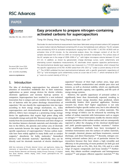
PAPER Easy procedure to prepare nitrogen-containing activated carbons for supercapacitors
Cite this: RSC Adv., 2014, 4, 39037
Tong-Xin Shang, Ming-Yang Zhang and Xiao-Juan Jin*
capacitors8 because of their high surface areas, large pore volumes, excellent conductivities and suitable pore sizes and textures, as well as chemical stability, which can signicantly improve the specic capacity, rate capability, and life cycle of energy storage systems. However, the specic capacitance of activated carbon is signicantly lower than theoretically expected, resulting in EDLCs with lower energy densities than predicted, which considerably hinders their practical application. Previous research has shown that9 higher capacitance is not only attributed to higher specic surface area, but is also affected by the chemical surface composition of carbon materials. The energy storage of EDLCs can be enhanced by enriching the surface of carbon materials with heteroatoms such as oxygen or nitrogen.10–12 These heteroatoms modify the electron donor/ acceptor properties of the carbon surface and are consequently expected to affect the charging of the electrical double-layer and yield pseudo-capacitance Faradaic reactions.13 Various surface modication methods have been investigated to introduce heteroatoms onto the surfaces of carbon materials, for example, chemical, plasma and ame treatments, coronal discharge, and direct uorination.14–18 Recently, nitrogen containing activated carbons (ACs) are of particular interest for researchers because they have shown a high versatility and efficiency in the processing of waste products (in both gas and liquid phase, such as CO2, NOx, H2S, SO2, CH4 and in a wide range of organic compounds and heavy metals).19–26 Furthermore, they obtain excellent complexants and heterogeneous catalysts27,28 and prepare efficient capacitor materials.29,30 The
电催化固氮催化剂研究进展
2020 年 12Dec. 20206 ]Issue 6江西科技师范大学学报Journal of Jiangxi Science & Technology Normal University电催化固氮催化剂研究进展谢锐匕曹波匕徐迅,多树旺>!2(1.江西科技师范大学材料与机电学院,江西南昌330013;2.江西省材料表面工程重点实验室,江西 南昌330013)摘 要:氨是重要的无碳能源载体,也是重要的化工原料,到目前为止,主要采用传统的,能耗高,温室气体排放大的Haber-Bosch 法合成0近年来,电催化固氮反应作为一种实现室温常压下绿色、可持续的氨合成工艺受到研究者的关注0本文简述了电催化固氮原理,综述了近几年来电催化固氮催化剂的研究进展,并对未来该领域的研究 进展进行展望0关键词:氨;催化剂;氨产率;法拉第效率中图分类号:TQ113.21文献标识码:A 文章编号:2096-854X (2020)06-0026-04Research Progress of Electrocatalytic Nitrogen Fixation CatalystXie Rui 1,2, Cao Bo 1,2, Xu Xun 1,2,L , Duo Shuwang 1,2% 1. Jiangxi Science & Technology Normal University, School of Materials Science andElectromechanical, Nanchang 330013, Jiangxi, P.R. China; 2. Jiangxi Key Laboratory of MaterialSurface Engineering, Nanchang 330013, Jiangxi, P.R. China )Abstract : Ammonia is an important carbon-free energy carrier as well as an important chemical material. So far,the traditional Haber-Bosch method with high energy consumption and large greenhouse gas emission has been mainlyused to synthesize ammonia. Recently, electrocatalytic nitrogen fixation as a green and sustainable ammonia synthesis process at room temperature and pressure has attracted the attention of researchers. Herein introducing the principle of electrocatalytic nitrogen fixation, summarizing the research progress of electrocatalytic nitrogen fixation catalyst inrecent years, and the future development trend is addressed finally.Key words : Ammonia; catalyst; ammonia yield; faraday efficiency—、弓I 言氨作为重要的化工原料在现代工业生产中具有重要的作用,在未来也有可能成为一种绿色无碳 能源代替含碳能源[1]。
Compressive Strength and Rapid Chloride Permeability of

Compressive Strength and Rapid Chloride Permeability ofConcretes with Ground Fly Ash and SlagOzkan Sengul 1and Mehmet Ali Tasdemir 2Abstract:Concretes with binary and ternary blends of portland cement,finely ground fly ash and finely ground granulated blast furnace slag were produced to investigate their effects on compressive strength and rapid chloride permeability.Portland cement was partially replaced by finely ground fly ash ͑Blaine specific surface:604m 2/kg ͒and finely ground granulated blast furnace slag ͑Blaine specific surface:600m 2/kg ͒.Two series of concrete with water/binder ratios of 0.60and 0.38were produced and for both water/binder ratios,portland cement was replaced by:͑i ͒50%fly ash;͑ii ͒50%blast furnace slag;and ͑iii ͒25%fly ash+25%blast furnace slag.At the high water/binder ratio,compressive strengths of the concretes with the pozzolans are lower compared to that of the portland cement concrete.At the low water/binder ratio,however,these strength reductions are less compared to the high water/binder ratio and compressive strength of the concrete produced with 50%slag was even higher than the portland cement concrete.The test results indicate the ground fly ash and ground granulated blast furnace slag greatly reduce the rapid chloride permeability of concrete.It was concluded that to reduce the chloride permeability of concrete,inclusion of pozzolans are more effective than decreasing the water/cement ratio.DOI:10.1061/͑ASCE ͒0899-1561͑2009͒21:9͑494͒CE Database subject headings:Fly ash;Slag;Compressive strength;Chlorides;Optimization;Concrete;Portland cements;Permeability .IntroductionCement production is an energy intensive process which also has an important effect on the environment.Producing one ton of portland cement releases about one ton of CO 2green house gas into atmosphere and as a result of this production 1.6billion tons of CO 2is released every year which is estimated at about 7%of the CO 2production worldwide ͑Mehta 2001;Malhotra 1999͒.The pressure of ecological constraints and environmental regulations are bound to increase in the coming years which will lead to greater use of supplementary cementitious materials such as fly ash or ground granulated blast furnace slag ͑GGBS ͒͑Aitcin 2000͒.There are two major reasons to use these by-products in concrete:͑1͒decreasing cement consumption by replacing part of cement with these pozzolanic materials and ͑2͒improving fresh and hardened concrete properties.In recent years,the reduction of water/cement ratio by using superplasticizers and usage of ul-trafine mineral admixtures lead to high performance concrete.Be-side the advantages,pozzolanic materials have certain drawbacks.To overcome some of the disadvantages and to be able to use the pozzolan in higher amounts,quality of the pozzolan can be im-proved.Chemical composition,particle-size distribution,fineness,andpozzolanic activity,and curing conditions of concrete are impor-tant factors affecting the properties of concretes with pozzolanic materials ͑ACI Committee 2321996;ACI Committee 2331995;ACI Committee 2341996͒.In recent years,it has been shown that the filler effect of mineral admixtures may be as important as their pozzolanic effects;according to some researchers,however,the filler effect can be more important than the pozzolanic effect ͑Goldman and Bentur 1993;Isaia et al.2003͒.Particle-size dis-tribution clearly plays a very important role in the rate of chemi-cal reactivity and in the water demand.Pozzolanic reaction takes place on the surface of the particles and increasing surface area has an important effect on pozzolanic activity.Thus,the fineness of the pozzolan is very important for the improvement of cement paste-aggregate interfacial zone,which is the weakest link in con-crete.In a previous investigation done by the research group of this study ͑Demir et al.2002͒,a coarse F type fly ash with a Blaine surface area ͑BSA ͒of 222m 2/kg was ground to four different finenesses such as 337,450,538,and 604m 2/kg.The purpose of the work mentioned was to study the effects of fly ash grinding on physical properties and strength development of concrete.It was concluded that as the fineness of fly ash increases,the compres-sive strength of concrete increases significantly.The particle size is an important factor also for the pozzolanic activity of the granulated blast furnace slag.Similar to the fly ash,the strength of slag concretes also increases with slag fineness ͑Tasdemir et al.1997;Niu et al.2002͒.Besides increasing the fineness,another solution to overcome the disadvantages of using high amounts of pozzolan,is to use ternary or quaternary blends of portland cement and pozzolans.By using different pozzolans together,some of the shortcomings can be compensated and more environmentally friendly concretes with specific properties can be obtained.The main objective of the work presented herein is to investi-gate the effects of ground fly ash and blast furnace slag on com-1Assistant Professor Doctor,Faculty of Civil Engineering,Istanbul Technical Univ.,34469Maslak,Istanbul,Turkey ͑corresponding author ͒.E-mail:sengulozk@.tr 2Professor Doctor,Faculty of Civil Engineering,Istanbul Technical Univ.,34469Maslak,Istanbul,Turkey.Note.This manuscript was submitted on December 17,2007;ap-proved on March 26,2009;published online on August 14,2009.Dis-cussion period open until February 1,2010;separate discussions must be submitted for individual papers.This paper is part of the Journal of Materials in Civil Engineering ,V ol.21,No.9,September 1,2009.©ASCE,ISSN 0899-1561/2009/9-494–501/$25.00.D o w n l o a d e d f r o m a s c e l i b r a r y .o r g b y S o u t h e a s t U n i v e r s i t y o n 12/12/13. C o p y r i g h t A S CE .F o r p e r s o n a l u s e o n l y ; a l l r i g h t s r e s e r v e d .pressive strength and chloride permeability of concrete at high replacement percentages.In this work,a finely ground low-lime fly ash ͑Blaine fineness of 604m 2/kg ͒and finely ground blast furnace slag ͑Blaine fineness of 600m 2/kg ͒were used in normal and high strength concretes to partially replace ordinary portland cement with a replacement amount of 50%.Concretes with ter-nary blends were also produced containing 25%fly ash and 25%pressive strength and rapid chloride ion permeability of the concretes were obtained at 28and 90days.To attain a durable concrete mixture low chloride permeability should be obtained.Achieving high compressive strength in a concrete structure is important for structural safety.The cost of concrete is also impor-tant from the applicability point of view.For this purpose a mul-tiobjective optimization method was performed in which the compressive strength was maximized but the rapid chloride per-meability and the cost were minimized.The responses in the op-timization were considered to be of equal importance.Experimental Details MaterialsSame ordinary portland cement ͑PC 42.5͒,finely ground fly ash,and finely ground blast furnace slag were used in the concretes.The 7-and 28-day compressive strengths of the standard RILEM-Cembureau cement mortars were 45.8and 57.3MPa,respec-tively.The fly ash used in this study was brought from Catalagzi power plant,which is located in the northwest coast region of Black Sea in Turkey.The blast furnace slag was obtained from Karabük production plant also located in the same region.Chemi-cal compositions of ordinary portland cement ͑OPC ͒,fly ash and slag are shown in Table 1.The fly ash and blast furnace slag were ground in a laboratory ball mill.The original Blaine fineness of the fly ash was 222m 2/kg and was increased to 604m 2/kg by grinding.The ground blast furnace slag used in this study also had Blaine fine-ness of 600m 2/kg.Some physical properties of the fly ash and slag are shown in Table 2.The average particle size of the fly ash used was relatively fine and characterized by a high density.In this study,the ground fly ash indicated in Table 2was used.Physical properties of the fly ash such as density and fineness change as it is ground.The physical changes due to grinding are:͑1͒the fineness of fly ash increases;͑2͒there is a remarkable increase in density by reduc-ing the porosity of the fly ash particles;and ͑3͒the spherical fly ash particles transform into the mostly irregular shapes;somesmall fly ash particles keep their original shapes.These conclu-sions were also reported in other works ͑Demir et al.2002;Sen-gul et al.2005͒.Effects of grinding on the fly ash particles are shown in Fig.1.Fig.2shows that the average particle size de-creases by grinding of the coarse fly ash.Table 1.Chemical Compositions of Portland Cement,Fly Ash,and Slag Oxide composition ͑%͒OPC ͑PC 42.5͒Fly ash Blast furnace slag SiO 220.060.240.5Fe 2O 3 3.6 6.7 1.2Al 2O 3 5.121.810.3CaO 63.2 2.532.2MgO 1.1 1.611.3SO 3 2.80.5 1.3K 2O 0.8 4.9 1.1Na 2O 0.30.50.35Cl -0.030.0060.0105Loss on ignition2.80.31.9Table 2.Some Physical Properties of Fly Ash and Blast Furnace SlagPropertyFly ashBlast furnace slag Before grinding After grinding Density2.00 2.51 2.86BSA,m 2/kg222604600Retained on 200m sieve,%12.00.00.0Retained on 90m sieve,%33.00.70.0Retained on 45m sieve,%50.03.70.2(a)Original fly ash particles (before grinding)(Blaine surface area:222m 2/kg)(b)Ground fly ash particles (Blaine surface area:450m 2/kg)(c)Ground fly ash particles (Blaine surface area:604m 2/kg)Fig.1.SEM images of ground fly ash particles:͑a ͒original particles;͑b ͒ground fly ash,BSA:450m 2/kg;and ͑c ͒ground fly ash,BSA:604m 2/kgD o w n l o a d e d f r o m a s c e l i b r a r y .o r g b y S o u t h e a s t U n i v e r s i t y o n 12/12/13. C o p y r i g h t A S CE .F o r p e r s o n a l u s e o n l y ; a l l r i g h t s r e s e r v e d .Pozzolanic ActivityPozzolanic activity is one of the critical properties of the mineral admixtures and there are different methods for the determination of the pozzolanic activity of these materials.For the fly ash used in this study,the pozzolanic activity test with lime was done according to ASTM C 311–85͑ASTM 1985a ͒.The test results obtained are given in Table 3together with ASTM C 618–85limits ͑ASTM 1985b ͒.An increase in the fineness of the fly ash leads to a substantial increase in its activity index at 7days.As seen in Table 3,increasing the BSA from 222to 604m 2/kg has resulted in an increase of approximately 80%in corresponding compressive strengths at 7days.Pozzolanic activity of the slag was obtained according to ASTM C989-06͑ASTM 2006͒which is based on the comparison of the compressive strengths of reference cement mortars and those of mortars produced with portland cement-slag blend.ASTM C989-06͑ASTM 2006͒mentions three grades for slag:Grade 80,Grade 100,Grade 120.The requirements for these grades and the results obtained for the slag used in this study are shown in Table 4.Based on these test results,the ground slag used can be classified as Grade 100.However,it should be noted that the results obtained are very close to the limits for Grade 120.Mixture ProportioningTwo series of concretes were produced with water/binder ratios of 0.60and 0.38.For both water/binder ratios;portland cement was replaced by:͑i ͒50%finely ground fly ash;͑ii ͒50%finely GGBS;and ͑iii ͒25%finely ground fly ash+25%finely GGBS.In all concretes,partial replacement of cement by fly ash and slag wason one to one weight basis.Portland cement concretes were also produced for each water/cement ratio.Basalt type coarse aggre-gate was used in all concretes to obtain better concrete strengths ͑Sengul et al.2002͒.The aggregate had a low porosity and high specific gravity.To obtain a better aggregate-cement paste inter-face,the aggregates were washed and used in saturated surface dry state.The aggregate grading,water-binder ratio,and the maximum particle size of aggregate were kept constant in all concretes.The grading curve of concrete aggregate was chosen between ISO A16-B16and closer to B16.Natural sand,crushed basalt sand,and crushed basalt No.I was used in the concretes.A superplasticizer was used in low water/binder concretes to main-tain approximately the same slump.The concrete mixtures were designated as follows:50S-60,50F-60,25FS-60,50S-38,50F-38,and 25FS-38.The first two digits show the partial replacement amount of cement by the fly ash or slag.The letters after the digits represent the binder type,where S shows the blast furnace slag and F indicates the fly ash.The last two digits indicate the water/binder ratio as %.For ex-ample 25FS-38represents the concrete with a water/binder ratio of 0.38and containing 25%fly ash+25%blast furnace slag.On the other hand,the mixtures 100PC-60and 100PC-38show port-land cement concretes with water/cement ratios of 0.60and 0.38,respectively.All mixtures were prepared in a laboratory mixer with vertical rotation axis by forced mixing.Details of the mixtures are shown in Table 5.All the specimens were demolded after 24h and stored in a water tank saturated with lime at 20°C until the testing day.Test ProcedureThree 150mm cubes were used for the standard compressive strengths of concretes.The rapid chloride ion permeability of the concretes was obtained according to ASTM C 1202–05͑ASTM 2005͒;three concrete disc specimens of 100mm in diameter and 50-mm thick were used for the test.The compressive strength and the rapid chloride permeability of concretes obtained at 28-and 90-day old specimens are given in Table 6.Results and DiscussionCompressive Strengths of ConcretesCompressive strengths of the concretes are illustrated in Figs.3and 4.As seen in Fig.3,for the water/binder ratio of 0.60,the compressive strength of the concrete with 50%slag replacement is slightly lower than the portland cement concrete both for 28and 90days.The compressive strength of the concrete with 50%fly ash replacement,however,is significantly low.For the 0.60water/binder ratio,at 28days the strength of the fly ash concrete is 59%of the portland cement concrete.At 90days,however,this ratio is 75%,which shows the significant strength development rate of the fly ash concrete between 28and 90days.Despite this substantial strength reduction compared to portland cement con-crete,at 0.60water/binder ratio and 28-day age,the compressive strength of the concrete with 50%fly ash is still over 34MPa and this concrete can be classified as a structural concrete.The pozzolanic reaction of fly ash in concrete depends on the break-down and dissolution of the glass phase which occurs when the pH of pore solution is higher than 13͑Fraay et al.1989͒.The pozzolanic reaction takes place between the fly ash and the CHParticle Diameter,µmC u m u l a t i v e p e r c e n t a g e501002575Fig.2.Particle-size distributions of fly ashes before and after grind-ingTable 3.Results of Pozzolanic Activity Index Test on the Fly AshCompressive strength at 7days,MPaFly ashBefore grinding,BSA:222m 2/kgAfter grinding,BSA:604m 2/kgExperiment7.914.2Class F in ASTM C618-85,min5.55.5Table 4.Results of the Slag Activity Index Test Slag activity index ASTM C989-06,minBlast furnace slag used in the studyGrade 80Grade 100Grade 1207-day index —75959128-day index7595115114D o w n l o a d e d f r o m a s c e l i b r a r y .o r g b y S o u t h e a s t U n i v e r s i t y o n 12/12/13. C o p y r i g h t A S CE .F o r p e r s o n a l u s e o n l y ; a l l r i g h t s r e s e r v e d .produced from the hydration of portland cement.This pozzolanic reaction is a slow process and is responsible for the low early strength of the high volume fly ash concrete.At the 0.60water/binder ratio,the compressive strength in-crease between 28and 90days is about 27%for the fly ash concrete,3%for the portland cement concrete,8%for the slag concrete,and 19%for the concrete with the ternary binder.This important strength increase of fly ash concrete indicates that the pozzolanic reaction of the fly ash continues at a higher rate for a longer period.The pozzolanic reaction of the blast furnace slag is more rapid when compared to that of the fly ash ͑Bijen 1996a ͒.For the dis-solution of the glass phase of blast furnace slag,pore water pH of about 12is enough and this alkalinity level occurs in a short period after mixing the slag-portland cement blend with water.This more rapid reaction is one of the factors causing a higher early strength of slag concretes.As shown in Fig.3,for the water/binder ratio of 0.60,the compressive strength of the concrete with ternary blend binder is between those of the slag concrete and fly ash concrete.The ter-nary binder containing 25%fly ash and 25%slag also has a significant strength increase between 28and 90days.The compressive strength of the concretes at 0.38water/binder ratios are shown in Fig.4.As seen in the figure,the strength of the slag concrete is higher than that of the portland cement con-crete at 28days and almost equal at 90days.The compressive strength of the concrete with 50%fly ash is 72.8MPa at 28days and 78.2MPa at 90days and this high volume fly ash concrete can be classified as a high strength concrete.For the water/binder ratio of 0.38concretes,the strength of the fly ash concrete is about 85%of the portland cement at both ages.For normal strength concretes,however,this strength ratio is 59%at 28days and 75%at 90days.When the results for the 0.38and 0.60water/binder ratios are compared,it can be concluded that the fly ash is much more effective at the low water/binder ratio for enhancing the strength of concrete.The better performance of fly ash at lower water/binder ratios was also reported in other studies ͑Demir et al.2002;Poon et al.2000;Lam et al.2000;McCarthy and Dhir 1999͒.Similar conclusions can also be drawn for the slag concrete and the concrete with the ternary binder.For the high water/binder ratio,the ratio of the compressive strength of slag concrete to that of portland cement is 92%at 28days and 96%at 90days,but this strength ratio increases to 105%at 28days and 99%at 90days for 0.38water/binder ratio.Mineral admixtures have two effects in concrete:pozzolanic effect and filler effect.A finer pore size distribution and less cap-illary pores can be obtained by using fine mineral admixtures in concrete.Fine pozzolanic materials also have an important effect on the aggregate-cement paste interface which is the weakest link in concrete and the thickness of this transition zone can be re-duced by using pozzolans ͑Bijen 1996b ͒.Better particle packing due to finer materials and the pozzolanic reaction may be the reasons for this enhancement.By the densification of the aggregate-cement paste transition zone,concrete becomes more homogeneous and higher strengths can be obtained.This im-provement may be more effective at lower water/binder ratios which can cause a better performance of the pozzolan.For the low water/binder ratio concretes,superplasticizers areTable 5.Mix Proportions and Some Properties of the Fresh Concretes Mix code100PC-6050S-6050F-6025FS-60100PC-3850S-3850F-3825FS-38Cement,kg /m 3348175176176450222221222Slag,kg /m 3017508802220111Fly ash,kg /m 3001768800221111Water,kg /m 3209210211211167168167168Water/binder0.600.600.600.600.380.380.380.38Superplasticizer,kg /m 30000 4.4 4.5 3.4 4.7Natural sand,kg /m 3503503497502500499487493Crushed basalt sand,kg /m 3380380375379377377368372Crushed basalt I,kg /m 3951952940951946945921933Slump ͑mm ͒9013014014080150110160Unit weight,kg /m 32,3892,3942,3752,3962,4362,4382,3892,415Air ͑%͒2.21.61.10.93.32.73.12.8Table 6.Mechanical Properties,Chloride Permeability,and Relative Cost of ConcretesWater/binder Mixture code Cube compressive strength of concrete͑MPa ͒ASTM C1202chloride ion penetration test͑Coulomb ͒Relative costs of concretes28days 90days 28days 90days 0.60100PC-6055.757.56,8135,500348.050S-6051.355.3703372288.850F-6034.243.3926161264.025FS-6042.951.2660376277.20.38100PC-3886.192.21,8771,780450.050S-3889.991.5395206366.350F-3872.878.2531144331.525FS-3883.186.6387217349.7D o w n l o a d e d f r o m a s c e l i b r a r y .o r g b y S o u t h e a s t U n i v e r s i t y o n 12/12/13. C o p y r i g h t A S CE .F o r p e r s o n a l u s e o n l y ; a l l r i g h t s r e s e r v e d .used to obtain enough workability.These chemical admixtures causes better dispersion of cement particles and higher early com-pressive strengths can be achieved due to the greater hydration rate in a well dispersed system ͑Mehta and Monterio 1993͒.The superplasticizer used in the 0.38water/binder ratio concretes may have helped for a better dispersion of the pozzolans which may have caused a less strength decrease when compared to the 0.60water/binder ratio concretes.The enhanced hydration in a well dispersed binder system also depends on the size of the mineral admixture.The particle sizes of the fly ash and slag used in this study are relatively fine and have Blaine finenesses of 600m 2/kg.The fine particle size of the pozzolans may have contributed to the better performance of concretes at the low water/binder ratio.Resistance to Chloride Ion PenetrationThe ASTM C 1202-05͑ASTM 2005͒rapid chloride ion penetra-tion test ͑RCPT ͒results of the concretes are given in Figs.5and 6.This test is based on the electrical conductivity of concrete.The concrete sample is subjected to a potential difference of 60V and the total charge passing through sample at the end of 6h is mea-sured and expressed in terms of Coulombs.A reduction in this total charge value indicates the better resistance to chloride ion penetration and lower permeability.As seen in the figures,for both water/binder ratios,pozzolan replacements caused great re-ductions in the rapid chloride permeability of the concretes.As shown in Fig.5,for the 0.60water/binder ratio and age of 28days,replacing 50%of portland cement by the fine slag caused a decrease of about 90%in the rapid chloride permeability of the concrete.Similarly,the reductions for the fly ash concrete and the concrete with the ternary binder are more than 86and 90%,re-spectively.For this water/binder ratio and 28-day age,the con-crete with the ternary binder has the lowest RCPT value.As seen in the figures,the rapid chloride ion permeability de-creases with age.For the water/binder ratio of 0.60,the total charge passing through the portland cement concrete decreases about 20%between 28and 90days.This decrease,however,is more substantial for the concretes containing high volume of poz-zolans.For the 0.60water/binder ratio,the reduction of the chlo-ride permeability between 28and 90days is about 47%for the slag concrete,83%for the fly ash concrete,and 43%for the concrete with the ternary binder.At 90-day age and 0.60water/binder ratio,the concrete with slag and with the ternary blend have RCPT values of about 7%of the portland cement concrete and with a value of 161Coulombs the fly ash concrete has the lowest value which is less than 3%of the normal concrete.If Figs.5and 6are compared,the effect of water/binder ratio on the rapid chloride permeability can be seen.For both 28and 90days,decreasing water/binder ratio from 0.60to 0.38caused a reduction of the RCPT value of about 70%for the portland ce-ment,44%for the slag concrete,and 42%for the concrete with the ternary binder.As a result of decreasing water/binder ratio,the total charge passing through the fly ash concrete reduced about 43%at 28days,but only about 10%at 90days.From these results,it can be concluded that the decrease in the water/binder10203040506070100PC-6050S-6050F-6025FS-60MixtureC u b e c o m p r e s s i v e s t r e n g t h (M P a )pressive strengths of concretes with water/binder ratio of 0.6020406080100100PC-3850S-3850F-3825FS-38MixtureC u b e c o m p r e s s i v e s t r e n g t h (M P a )pressive strengths of concretes with water/binder ratio of 0.3855003721613762000400060008000100PC-6050S-6050F-6025FS-60MixtureR a p i d c h l o r i d e p e r m e a b i l i t y (C o u l o m b )2890Fig.5.Rapid chloride permeability test results of concretes with water/binder ratio of 0.60206144217500100015002000100PC-3850S-3850F-3825FS-38MixtureR a p i d c h l o r i d e p e r m e a b i l i t y (C o u l o m b )90Fig.6.Rapid chloride permeability test results of concretes with water/binder ratio of 0.38D o w n l o a d e d f r o m a s c e l i b r a r y .o r g b y S o u t h e a s t U n i v e r s i t y o n 12/12/13. C o p y r i g h t A S CE .F o r p e r s o n a l u s e o n l y ; a l l r i g h t s r e s e r v e d .ratio affects the RCPT value of the portland cement concrete more than those of the concretes with high amount of pozzolans.For the water/binder ratio of 0.38;at 28days,the concrete with the ternary binder and the slag concrete have the lowest RCPT values,which are about 20%of the portland cement con-crete.At 90days,however,the fly ash concrete has the lowest RCPT value which is about 8%of the portland cement concrete value.At the low water/binder ratio,the chloride permeability of pozzolanic concretes also decreased substantially between 28and 90days.For the 0.38water/binder ratio,between 28and 90days the RCPT value of portland cement concrete decreased only about 6%,however,decreases of 48,73,and 44%were obtained for the slag concrete,fly ash concrete,and the ternary binder concrete,respectively.In this study,the total replacement ratio of portland cement by the pozzolanic materials was 50%for all the mixtures.In the binary blended mixtures,concretes contain 50%slag or fly ash,and the ternary blended mixtures contain 25%slag and 25%fly ash which also correspond to 50%replacement.As seen in Figs.5and 6,for both water/binder ratios,the RCPT results of the ter-nary blended mixtures at 28days are slightly lower than those of the slag or fly ash concretes.At the age of 90days,however,the RCPT results of the ternary blended concretes are almost the same as the slag concretes and higher than those of the fly ash concretes.For the ternary blended mixtures,the reduction of the RCPT results between 28and 90days were also not lower com-pared to those of the binary blended concretes.In theory,for the ternary blended mixtures with equal percentage of fly ash and slag replacement,greater reduction in chloride permeability may be expected compared to those of the binary blended mixtures.However,based on the test results,it seems that such an improve-ment was not obtained by the ternary blended mixtures prepared.The fly ash and slag used have almost the same Blaine finenesses which indicate that they have similar particle sizes.Due to this similar particle sizes,the particle packing in the ternary blended mixtures may not be substantially different compared to those of the binary blended concretes and as a result the RCPT of the ternary blended concretes were not substantially lower than those of the binary blended concretes.In this study,all the specimens were cured in water until the testing day and for both water/binder ratios,the substantial reduc-tion of the chloride ion permeability of pozzolanic concretes be-tween 28and 90days indicates the high pozzolanic activity of the pozzolans taking places during this period.The ASTM C 1202-05͑ASTM 2005͒classifies concretes in terms of chloride ion pen-etrability and based on this classification,the concretes containing the ground fly ash and slag can be considered as concretes of very low permeability.The lower chloride permeability of the concretes with high volume pozzolans is a result of a denser microstructure.The poz-zolanic reaction may cause lower amount of capillary pores and clogging of the pores,which reduces chloride ion transport in concrete ͑Li and Roy 1986͒.Improvement of the aggregate-cement paste interface by the pozzolanic reaction may also play a role in decreasing the chloride ion permeability.Better chloride ion resistance of high volume fly ash concretes was also shown in other studies ͑Sengul et al.2005;Zhang et al.1999͒.The ground fly ash and slag used in this study has a high fineness which may have contributed to obtaining lower chloride ion permeability ͑Dhir and Jones 1999͒.Decreasing the water/cement ratio of a concrete reduces the amount of capillary pores which are mainly responsible for thepermeability of the concrete.Even though the RCPT value of the portland cement concrete is reduced about 70%by lowering the water/cement ratio,the values for the portland cement concrete at 0.38water/cement ratio are still 2times or even more higher than those of the concretes with pozzolans at 0.60water/binder ratio.This result indicates that to reduce the chloride permeability of portland cement concrete,inclusion of pozzolans are more effec-tive than reducing the water/cement ratio.Reduced capillary pores and reduction in their connectivity due to the pozzolanic reaction and better particle packing may be the reasons behind the better performance of the concretes with high amount of poz-zolans.Also,as indicated above,between the ages of 28and 90days,the chloride permeability of the concretes with pozzolans decreased substantially compared to those of the portland cement concretes.Pozzolanic reaction is relatively slow compared to the hydration of portland cement,which is the main reason of the low early age strength or high early age permeability of the concretes containing high volumes of pozzolanic materials.At later ages,however,the pozzolanic materials can be more effective in im-proving concrete properties due the pozzolanic reaction continu-ing at a higher rate for a longer period.It should also be noted that curing conditions is more important for such concretes.As seen in Table 5,the decrease in the water/binder ratio was obtained by both reducing the water amount and increasing the binder content which may have also contributed to the better per-formance of the low water/binder ratio concretes.Studies show that,for a same water/binder ratio,increasing the binder content can also help to reduce the permeability of the concrete ͑Buenfeld and Okundi 1998;Dhir et al.1996͒.OptimizationOptimization is a procedure for obtaining the best possible option and it is an important tool for decision making process.This procedure is based on defining performance criteria ͑objective functions ͒,independent and dependent variables,and formulation of the parameters based on constraints ͑Brandt and Marks 1993͒.For the optimization of concrete mixtures;the performance crite-ria may be the strength,permeability properties,fracture proper-ties,durability characteristics,cost,or other concrete properties.The independent variables,for example,may be the amounts of constituent materials.The responses ͑dependent variables ͒,which are based on the independent variables,are compared to the per-formance criteria.In the optimization of concrete mixtures,con-crete properties such as the compressive strength obtained for a given mixture design may be one of the responses.Optimization usually involves considering several responses simultaneously,such as high strength and low cost.To optimize several responses,multicriteria optimization techniques were used in this study.A useful approach for the optimization of multiple responses simultaneously is to use desirability functions which reflect the levels of each response in terms of minimum and maxi-mum desirability ͑Sengul et al.2005͒.A desirability function ͑d j ͒varies over the range of 0Յd j Յ1.In case of maximizing and minimizing the individual responses,d i is defined by Eq.͑1͒and ͑2͒,respectively ͑Myers and Montgomery 2002͒d j =ͫY j −min f jmax f j −min f jͬt͑1͒D o w n l o a d e d f r o m a s c e l i b r a r y .o r g b y S o u t h e a s t U n i v e r s i t y o n 12/12/13. C o p y r i g h t A S CE .F o r p e r s o n a l u s e o n l y ; a l l r i g h t s r e s e r v e d .。
丙烷氨氧化制丙烯腈催化剂及工艺进展_白尔铮
专家综述与展望收稿日期:2004-02-18作者简介:白尔铮(1945-),男,高级工程师,长期从事石油化工科技情报调研工作,发表论文多篇。
丙烷氨氧化制丙烯腈催化剂及工艺进展白尔铮(中国石化上海石油化工研究院,上海201208)摘 要:丙烷氨氧化制丙烯腈是一种具经济吸引力的潜在丙烯腈生产路线。
对近年来这方面的催化剂开发、反应机理、技术经济性和发展趋势作了评述。
通过比较发现,钒铝氧氮催化剂在丙烷氨氧化体系中具有较钒钼和钒锑混合氧化物催化剂更高的空间收率。
关键词:丙烷;氨氧化;丙烯腈;催化剂;钒铝氧氮中图分类号:TQ226.61;TQ426.94;TQ032.4 文献标识码:A 文章编号:1008-1143(2004)07-0001-06Advances in propane ammoxidation catalysts and processes formanufacture of acrylonitrileBAI Er -zheng(Sinopec Shanghai Research Institute of Petrochemical Technology ,Shanghai 201208,China )A bstract :Propane ammo xidation to acrylo nitrile is a potential and economically attractive route for acrynitrile production .Latest advances in the cataly sts ,reaction mechanism ,techno -economics and trend of development in this field were reviewed .Comparison investigation indicated that vanadium a -luminum o xynirtride catalysts show ed superio r acry lonitrile productivity to vanadium -molybdate and v anadium -antimonate mixed o xides catalysts in propane ammoxidation .Key words :propane ;ammoxidation ;acrylo nitrile ;catalyst ;vanadium aluminum oxy nirtride C L C num be r :TQ226.61;TQ426.94;TQ032.4 Docum ent code :A A rticle ID :1008-1143(2004)07-0001-06 丙烯腈是重要的有机化工原料,主要用作腈纶单体和ABS (丙烯腈-丁二烯-苯乙烯)三元共聚体等原料。
超临界方法煤的液化
Coal liquefaction using supercritical toluene–tetralinmixture in a semi-continuous reactorS.Sangon,S.Ratanavaraha,S.Ngamprasertsith,P.Prasassarakich *Department of Chemical Technology,Faculty of Science,Chulalongkorn University,Bangkok 10330,ThailandReceived 21February 2005;received in revised form 29June 2005;accepted 1July 2005AbstractLiquefaction of Banpoo coal and Mae Moh coal using supercritical toluene–tetralin mixture was performed in a semi-continuous apparatus at a temperature ranging from 370to 490-C and under pressures up to 12.2MPa.The addition of tetralin to toluene increased the coal conversion and the liquid yield by the stabilization of radical fragments and inhibition of radical recombination.The effect of solvent pre-swelling treatment and catalyst impregnation on conversion and liquid yield was also examined.The combination effects of catalyst and swelling enhanced conversion and the liquid yield of sub-bituminous coal.The yield of coal liquid at the condition of 490-C and 10MPa with toluene–tetralin reached a maximum 45wt.%(in daf coal)with THF as the swelling agent and ZnCl 2as the catalyst.The coal residue,after extraction,maintained most of its heating value and had a lower sulfur content.D 2005Elsevier B.V .All rights reserved.Keywords:Coal;Supercritical fluid;Liquefaction;Co-solvent;Catalyst1.IntroductionIntense efforts have been made to liquefy coal in the past.Processes such as pyrolysis,solvent extraction and catalytic liquefaction have had varying degrees of success.Such processes have indicated that a significant coal conversion and coal liquid yield may be obtained.Presently,supercritical fluid extraction is increasingly of interest because of its low viscosity and controllable solvent power.Supercritical fluid extraction (SCFE)has the advantage of a high mass transfer rate allowing easy separation of the extract (coal liquid and solvent)from the coal residue,thus overcoming a major problem of the conventional liquefaction process [1,2].Supercritical fluids such as toluene have previously been reported as good media for extraction of coal.Though a lower conversion is achieved in supercritical fluid extraction,the addition of a co-solvent such as tetralin or ethanol improves coal conversion and liquid yield [3].The co-solvent should have a hydrogen-donor capability to stabilize the free radicals generated and therefore reduce considerably the repolymerization reaction.Hydrogenating SCFE has also been studied using toluene with different combinations of molecular hydrogen,a hydro-gen-donor solvent and catalyst;molecular hydrogen had a negative effect on coal conversion and coal liquid yield [4].The effect of the extraction conditions and solvent type (hexane,benzene,toluene and toluene–tetralin mixture)on liquid yield and properties was studied to clarify the relation between the coal yield,the solvent power of supercritical fluid and the reaction occurring during extraction [5].The effect of temperature and solvent density on the characteristic of extracts (saturated HC,aromatics,resins and asphaltenes)was also studied for SCFE with toluene.Lighter compounds were found to increase with increasing temperature and with the addition of 5mol%ethanol [6].It was reported that,for liquefaction using supercritical toluene and co-solvent (methanol and ethanol),extraction conditions affected the elemental composition,thermogravimetric character and group composition of extracts and their fractions.The liquefaction of coal using supercritical alcohol has been reported [7,8].Recently,when supercritical alcohols (ethanol and isopropanol)were used in coal liquefac-tion,an increase in either temperature or pressure was found to increase liquid yield.Additionally,the extracts were charac-terized for eight discrete fractions with well-defined chemical functionality [9].0378-3820/$-see front matter D 2005Elsevier B.V .All rights reserved.doi:10.1016/j.fuproc.2005.07.007*Corresponding author.Tel.:+6622187517;fax:+6622555831.E-mail address:ppattara@chula.ac.th (P.Prasassarakich).Fuel Processing Technology 87(2006)201–207/locate/fuprocImprovement in coal liquefaction can be achieved by impregnating the catalyst into the coal rather than mixing with the coal as powder.Besides improving catalyst behavior by dispersion,the activity of the catalyst may affect the structure of the coal causing the weakened structure that is more susceptible to depolymerization reaction.One method to modify coal structure is solvent swelling.The swelling may facilitate the impregnation by the catalyst,thus the pretreatment can increase conversion[10–12].The beneficial effects depend on the nature of the catalyst and swelling agent and the coal rank[13].Although much is known about supercritical extraction and catalytic liquefaction,the system is complex and more remains to be discovered.Maximizing liquid yield requires a balance between temperature,pressure,residence time and the addition of appropriate catalysts.This work examines the use of hydrogenated solvent under supercritical condition,catalyst and coal swelling prior to extraction.Coal liquefaction using a toluene–tetralin mixture in a semi-continuous reactor was studied and the effects of various parameters on coal conversion and liquid yield were investigated.The extracts were characterized by the simulated distillation chromatogra-phy method and the coal residue was also analyzed.2.Experimental2.1.Impregnation of swollen coal with the catalyst prior to liquefactionThe coal used in this study was sub-bituminous coal from the Banpoo mine and lignite from the Mae Moh mine in Lampang province,northern Thailand.The coal samples were ground,sieved(particle size:<1mm,1–2mm and4–5mm) and air-dried.Proximate and ultimate analyses and sulfur distribution are presented in Table1.The coal samples were predried at110-C in an oven.For pre-swelling experiments, coal was mixed with the swelling solvent to give a solvent to coal ratio of approximately3:1and was stirred for18h at room temperature.The solvent was removed by evaporation under reduced pressure and the coal was dried as described previously.For impregnation,the catalyst was loaded onto the swollen coal at0.5%metal loading on daf basis.The swollen coal was impregnated with a water solution of ZnCl2 or pentane solution of Mo(CO)6overnight and then dried in an oven.2.2.Coal liquefactionThe liquefaction experiments were carried out in a50-ml stainless steel reactor.A schematic diagram of the semi-continuous reactor is given in Fig.1.For each experiment,20g of air-dried coal were loaded in the reactor.The nitrogen was charged into the reactor and the heater was turned on to reach the desired temperature and pressure.The solvent was pumped to the reactor at a rate of2ml/min with the exit closed to permit the build-up of the desired pressure and temperature.The reactor pressure was controlled by a back-pressure regulator valve.The weight hourly space velocity(WHSV)of the toluene–tetralin mixture(70/30v/v)was estimated as5.38hÀ1 in the reactor.At the end of each experiment,the furnace was withdrawn and the reactor was cooled down to room temperature.The coal residue was recovered by filtration and dried for4h in an oven at100-C.The weight loss of the coal sample after extraction on daf basis defined the degree of coal conversion.The extract product was collected,the solvent was removed by rotary evaporation under vacuum and the coal liquid was analyzed.The coal conversion and liquid yield were calculated by the following expressions:%Conversion¼W sample;dryÀW residueÀÁsample;dafÂ100ð1Þ%Liquid yield¼W liquidW sample;dafÂ100ð2Þwhere W liquid and W residue is the mass of coal liquid and coal residue,respectively.W sample,dry and W sample,daf is the mass of starting sample at dry basis and dry ash free basis,respectively.2.3.Extract and residue analysisIn this study,the coal liquid was analyzed by Simulated Distillation Gas Chromatography(Varian Model CP-3800) according to ASTM D2887.Star Simulated Distillation version 5.5software was used for data collection and processing.The coal liquid was dissolved in CS2(1%v/v).CP-SIL5CB15 mÂ0.25mm was used for separation.The oven temperature was raised from30-C to370-C at a constant heating rate of20 Table1Proximate and ultimate analyses of coalBanpoo1Banpoo2Mae Moh Proximate analysis(wt.%db)Ash 5.410.340.2V olatile matter42.738.835.4 Fixed carbon51.950.924.4Ultimate analysis(wt.%daf)C73.067.656.5H 5.8 4.79.5N 1.00.9 2.5S 1.90.6 1.3O(by diff.)18.326.230.2 Heating value(dry,MJ/kg)24.522.710.8Ash constituent(wt.%)SiO2NA0.4025.31Al2O3NA 2.1914.68Na2O NA– 1.06K2O NA0.27 2.29 CaO NA27.2212.85 MgO NA 4.19 2.78Fe2O3NA14.2618.05 SO3NA50.6321.98 TiO2NA–0.39 BaO NA0.730.19 Others NA0.110.42S.Sangon et al./Fuel Processing Technology87(2006)201–207 202-C/min.The distillation curve was evaluated to fractions as follows:IBP—200-C,naphtha;200–250-C,kerosene;250–350-C,light gas oil;350–370-C,gas oil;and 370-C—FBP,long residue.The raw and leached coal was analyzed for proximate analysis and total sulfur by ASTM methods D2492and D3177.The heating value of raw coal and coal residue was determined according to ASTM D2015.Carbon,hydrogen and nitrogen analyses were performed using a CHN analyzer (Perkin Elmer PE 2400Series II).3.Results and discussion 3.1.Effect of solvent typeIn liquefaction,radicals are produced through the thermal decomposition of the coal.Some radicals recombine with each other or with the coal while others decompose to small molecules.In the presence of tetralin,most of the radicals are stabilized by abstracting hydrogen from the tetralin which inhibits both the recombination with coal and the further decomposition of the radicals.For tetralin addition (10–70%)to toluene,coal liquid yield increased with tetralin content until it remained unchanged when tetralin content was above 30vol.%[3].Thus,tetralin content of about 30vol.%may be sufficient to inhibit the recombination of radicals.During the liquefaction with toluene–ethanol mixture,ethanol molecule or active chemical species produced by the reaction between ethanol and coal altered the coal structure.Thus,the addition of about 10%ethanol promoted the alteration of the coal structure and the coal liquid because supercritical alcohol can act as a hydrogen donor [14].The supercritical coal liquefaction was carried out using various solvents at 450-C and 10MPa for 90min.Fig.2shows the result of %conversion and %liquid yield.Toluene–tetralin solvent resulted in a %conversion (47–62%)and %liquid yield (25–28%)that was double the rate of the one solvent (conversion =24–28%,liquid yield =9–12%).Thetoluene–tetralin mixture for this composition had critical properties calculated by the HYSYS program as follows:T c =361.1-C,P c =4.07MPa.Thus,toluene–tetralin at a ratio of 70:30v/v was chosen for liquefaction of Banpoo coal.3.2.Effect of coal particle sizeThe effect of varying particle size on %conversion and %liquid yield of coal liquefaction using toluene–tetralin (70/30v/v)is shown in Fig.3.The condition was kept constant at a temperature of 450-C,pressure of 10MPa and time of 90min.For both lignite and sub-bituminous coal,the conversion and liquid yield increased as the particle size decreased.Varying the particle distribution affected initial particle size area for contact with the solvent which increased rapidly with decreasing particle size.Lignite gave slightly higher liquid yield (26–33%)than sub-bituminous coal (22–30%)since lignite has a weak structure which is susceptible todepolymerization.TolueneEthanolToluene- 20% Ethanol Toluene- 10% Tetralin Toluene- 30% Tetralin%w t (d a f )Fig.2.Effect of solvent type on liquid yield and coal conversion for non-catalytic liquefaction of Banpoo2(1–2mm).T =450-C,P =10MPa,time=90min.Temperature controllerTCPTSolvent reservoirNitrogen cylinderHPLC pumpPreheaterCoolerTubular furnaceReactorBack pressure regulatorSampling vesselTrapVentIce bathPressure TransducerFig.1.Schematic diagram of the semi-continuous reactor system.S.Sangon et al./Fuel Processing Technology 87(2006)201–207203However,lignite yielded lower conversion (37–53%)than sub-bituminous coal (54–70%)due to the high ash in lignite.High ash lignite (40%ash)has more inactive sites,due to the presence of inorganic matters,than sub-bituminous coal (10%ash)and thus the solvent could penetrate and convert only the organic matter to liquid and gas.It might also be found that the sub-bituminous coal gives a higher gas yield than bined effects of swelling and catalyst impregnation Via the modification of the coal structure by solvent swelling,dissolution activity of the catalyst can be promoted and the weakened structure would be more susceptible to depolymer-ization.The swollen coal network would lead to pore expansion with the swelling facilitating impregnation by the catalyst and diffusion of the toluene–tetralin mixture to the reactive sites of the coal.From the study of the solvent types and particle size effects,the following liquefaction experiments were performed using toluene–tetralin (70/30v/v)and a coal particle size of 1–parative conversion and liquid yield for catalyst impregnation-swollen lignite and sub-bituminous coal are given in Table 2.For the non-catalytic liquefaction of sub-bituminous coal,THF and pyridine swelling provided a greater conver-sion (75–78%)but the liquid yield remained unchanged (27–29%).The deposition of ZnCl 2with THF swelling increased the conversion and liquid yield substantially to 89%and 37%,respectively.This suggests that swelling introduces macroscopic cracks and fission in the coal matrix which aid the dispersion of ZnCl 2on the coal surface.The beneficial effects depend on the nature of the swelling agent and the coal rank.When the coal matrix expands because of swelling,the internal surface of the coal macromolecule becomes more accessible to reagent and coal reactions are facilitated.In contrast,ZnCl 2with pyridine did not have any advantage (80%conversion and 29%liquid yield).Though pyridine was the most effective swelling solvent,pyridine actually sup-pressed coal conversion and liquid yield.It is postulated that too high pyridine in the coal network (swelling ratio =1.68)lowered the ZnCl 2concentration in coal and ZnCl 2activity decreased in high swollen coal.The surface area for catalyst/coal contact resulting from swelling in THF was appropriate for sub-bituminous coal liquefaction which yielded high conversion and liquid yield.To examine the effects of coal rank and catalyst,lignite was examined in the same manner as sub-bituminous coal.The results are summarized in Table 3.The non-catalytic liquefac-tion with THF and pyridine swelling gave 45–52%conversion and 33–36%liquid yield.Swelling of lignite with THF or pyridine slightly improved conversion and liquid yield compared with the non-swelling coal liquefaction (30%liquid yield).It can also be noted that the conversion of lignite is much lower than that of sub-bituminous coal.One reason is that lignite with high ash exhibited a lower swelling ratio (1.16in THF)than sub-bituminous coal (1.35in THF)because the high ash lignite has less organic matter for swelling and a high crosslink structure among acidic functional groups while sub-bituminous coal has an aromatic structure with fewer cross-links.The sub-bituminous coal swelled very well in polar solvents such as THF and pyridine.For catalytic ZnCl 2liquefaction with pre-swelling,the conversion remained unchanged but the oil yield actually decreased compared with non-catalytic liquefaction.In con-trast,the deposition of Mo(CO)2increased the conversion to 56%and the oil yield increased substantially to 42%.These beneficial effects depend on the nature of the swelling agent and coal rank.ZnCl 2is an efficient catalyst for low ash coal containing low Na and K.For Mae Moh coal with high ash,the alkaline metal in the coal reacted with the ZnCl 2catalyst,so the catalyst concentration in the system was decreased and resulted in an inefficient catalytic process.Thus,ZnCl 2is not an efficient catalyst for high ash coal [15].3.4.Effects of pressure and temperatureTHF is the only solvent capable of effectively dispersing the catalyst in Banpoo coal.For the catalytic process,ZnCl 2was used as the catalyst and THF as the swelling solvent.Fig.4shows liquid yield and coal conversion as a function ofTable 2Effect of pre-swelling and catalyst on supercritical liquefaction using toluene –tetralin (70/30v/v)CoalSwelling solvent Catalyst Conversion (wt.%daf)Liquid yield (wt.%,daf)Banpoo2(1–2mm)sub-bituminousNone None 6228THF None 7527Pyridine None 7829None ZnCl 26327THF ZnCl 28937Pyridine ZnCl 28029Mae Moh (1–2mm)ligniteNone None 4430THF None 4536Pyridine None 5233None ZnCl 24426THF ZnCl 24428PyridineMo(CO)65642Condition:T =450-C,P =10MPa,time =90min.Banpoo 2:swelling ratio=1.35in THF,1.68in pyridine.Mae Moh:swelling ratio=1.16in THF,1.33in pyridine.62%54%30%28%53%44%37%33%30%26%Particle size (mm)%w t (d a f )Liquid yield Liquid yield22%Banpoo 2:Mae Moh:Fig.3.Effect of coal particle size on liquid yield and coal conversion for non-catalytic liquefaction using toluene–tetralin (70/30v/v).T =450-C,P =10MPa,time=90min.S.Sangon et al./Fuel Processing Technology 87(2006)201–207204pressure for catalytic and non-catalytic liquefaction using toluene–tetralin (70/30v/v).It can be seen that a rise in pressure causes an increase in liquid yield as a result of the increase in solvent power (or solvent density).To compare the performance with regard to liquid yield,liquefaction was conducted resulting in 39%for ZnCl 2catalytic and 30%for non-catalytic process at 450-C and 12MPa.The coal conversion and liquid yield of catalytic liquefaction was higher than that of non-catalytic liquefaction for all pressures.Interestingly,the conversion of catalytic liquefaction increased with pressure up to 10MPa and then decreased at 12MPa.The reason for this discrepancy in the coal conversion is not clear at this time.One possible reason is that at very high pressure,the impregnated catalyst in coal may be disrupted or loosened due to an increase in fluid density and consequently the catalyst activity decreases.However,the liquid yield still increases slightly in the pressure range between 10and 12MPa due to high diffusivity of the supercritical solvent.The effect of temperature on liquid yield and coal conversion for catalytic and non-catalytic liquefaction usingtoluene–tetralin (70/30v/v)is illustrated in Fig.5.The coal conversion and liquid yield of catalytic liquefaction was higher than that of non-catalytic liquefaction at all temperatures.For ZnCl 2catalytic liquefaction,the liquid yield was a maximum of 45%(daf)at 490-C and 10MPa;the corresponding coal conversion was 33%.As expected,an increase in temperature resulted in an increase in the coal conversion and liquid yield.It should also be observed that the temperature has a more pronounced effect than the pressure on the liquid yield.Another interesting effect is that for catalytic liquefaction,the coal conversion increased with temperature approaching a maximum value (89%)and then slightly decreased.At high temperature,the thermal decomposition drastically accelerated.However,the liquid yield increased slightly in the temperature range of 450and 490-C due to the pronounced ability of the supercritical solvent.Table 3shows the comparison of supercritical liquefaction results from this work with previous investigations.The coal conversion and liquid yield depend on process conditions,swelling solvent,catalyst,catalyst type and coal rank.Our results compare well with those that others obtained athigherPressure (MPa)%w t (d a f )Non-Catalytic, Banpoo 1:ZnCl 2 Catalytic, Banpoo 2:Fig.4.Effect of pressure on liquid yield and coal conversion for non-catalytic and catalytic liquefaction using toluene –tetralin (70/30v/v).Coal particle size =1–2mm,T =450-C,time=90min.%w t (d a f )Temperature (o C)Non-Catalytic, Banpoo 1:ZnCl 2 Catalytic, Banpoo 2:Fig.5.Effect of temperature on liquid yield and coal conversion for non-catalytic and catalytic liquefaction using toluene–tetralin (70/30v/v).Coal particle size=1–2mm,P =10MPa,time=90min.Table 3Comparison of coal liquefaction from this work and other investigation InvestigatorSupercritical fluid Swelling solvent Catalyst Coal class Condition Coal conversion (wt.%,daf)Liquid yield (wt.%,daf)Shishido et al.(1991)Toluene–tetralin ––Sub-bituminous 380-C,20MPa 6459Toluene–ethanol 5854Canel et al.(1990)Toluene ––Bituminous Supercritical 2814Toluene–H 2Lignite 550-C 5017Toluene–tetralin 10MPa 5923Pinto et al.(1999)–THF ZnCl 2Sub-bituminous 400-C 916727TBAHH 27.9MPa 56Artok et al.(1992)–Mo(CO)6Lignite 275-C NA 7THF Mo(CO)6Bituminous H 27MPa NA 15TBAH ATTM Sub-bituminous NA 19Joseph J.T.(1991)–TBAH Mo(CO)6Bituminous 400-C8737THF Sub-bituminous H 21100psig 8848This workToluene–tetralin––Sub-bituminous 490-C,10MPa 6333THFMo(CO)6Lignite450-C,10MPa 5642ZnCl 2Sub-bituminous490-C,12MPa8545TBAH=tetrabutylammonium hydroxide,ATTM=ammonium tetrathiomolybdate,(NH 4)2MoS 4.S.Sangon et al./Fuel Processing Technology 87(2006)201–207205temperature and pressure.The oil yield might also be related to the ash and oxygen content of the coal[3].One advantage of the semi-continuous reactor is the separation of toluene–tetralin and coal extract from the coal residue.The supercritical fluid stream was passed through a bed of coal particles,and the extracted oil was carried with the solvent thus effecting a complete separation between the extracted coal liquid and the coal(Fig.1).Finally,the coal liquid was separated from the continuous stream of pared with the previous work by various investigators,the liquefaction in a batch reactor has one disadvantage which is that the separation of the liquid extract from coal and solvent requires a tedious procedure to achieve any accuracy.In this work,the toluene–tetralin mixture was separated from coal liquid by vacuum evaporation and recovered about96%of solvent feed.For process development,the loss of solvent could be minimized to less than1%by an optimal process engineering design.3.5.Analysis of coal liquidThe coal liquid was the product of ZnCl2catalytic liquefaction using toluene–tetralin.It was divided into naphtha,kerosene,light gas oil,heavy gas oil and long residue by using Simulated Distillation Chromatography.In this study, the oil yield increased with temperature.Fig.6illustrates the effect of temperature and pressure on the yields of distillation fractions of liquid from THF pre-swelling Banpoo coal.It can be seen that the content of naphtha and kerosene increased while light gas oil and gas oil decreased with increasing temperature.At a constant pressure of10MPa,the long residue had a high value(45–59%)at400–490-C and increased with temperature.At high temperature(490-C),naphtha was not found.The reason is that repolymerization probably occurred due to insufficient hydrogen from tetralin to stabilize the large amount of free radicals occurring when the maximum liquid yield of45%was achieved.As pressure increased,long residue decreased and naphtha increased and the oil distribution at this condition(450-C,12 MPa)had similar characteristics to Thai crude oil from Lankrabue,northeastern Thailand.It can be concluded that high temperature and pressure would benefit the formation of lighter components,e.g.naphtha,kerosene and light gas oil. The increase in temperature and pressure,leading to more severe thermolysis of the coal structure,results in an increase in the amount of lighter and intermediate compounds at the expense of the higher MW compounds.The coal extract at optimum process conditions included naphtha14%,kerosene 21%,light gas oil27%,gas oil5%and long residue33%by weight.These values became the foundation for turning the oil of Banpoo coal into liquid fuel as well as raw chemical materials.3.6.Effects of variables on coal residue propertiesThe proximate analysis of coal residue from catalytic liquefaction using toluene–tetralin was studied.Table4shows the effect of temperature and pressure on coal residue properties in terms of sulfur reduction and the increase in heating value.The coal residue was the product of ZnCl2 catalytic liquefaction with THF pre-swelling.As temperature increased,the volatile matter deceased and fixed carbon increased which resulted in an increase in heating value.A similar trend was observed for the pressure effect in that the volatile matter decreased and fixed carbon increased with increasing pressure.It was also found that the increase in heating value ranges from33%to45%and sulfur reduction from7%to39%was dependent on the process conditions.The coal residue from catalytic liquefaction at450-C and10MPa which had lower sulfur content(0.29%)and higher heating value(32.6MJ/kg)will be considered for use subsequently in a gasification process.Furthermore,the coal residue or char can be used in fluidized combustion,in gasification or for hydrogen production since such residues are essentially composed of porous low temperature char which has no agglutinating tendency and releases little or no tarry matter during heating.4.ConclusionsSupercritical toluene is effective for coal extraction at high pressure in a relatively short time.Besides this,a hydrogenTable4Proximate analysis of coal residue from catalytic liquefaction a using toluene–tetralin(70/30v/v)for Banpoo2(1–2mm)10MPa7MPa12MPa400-C450-C490-C450-C450-C Proximate analysis(db)Ash7.811.110.511.911.1V olatile matter22.518.015.530.214.9 Fixed carbon69.770.974.057.974.0 Sulfur(%)0.450.340.290.420.31 Sulfur reduction(%)7.229.539.413.537.2 Heating value(dry,MJ/kg)32.132.632.630.332.9a THF as swelling agent,ZnCl2as catalyst.Time=90min.400 C 10 MPa450 C 10 MPa490 C 10 MPa450 C 12 MPa Crude%wt(28%)(37%)(45%)(39%)Fig.6.Effect of temperature and pressure on oil distribution of coal liquid forZnCl2catalytic liquefaction using toluene–tetralin(70/30v/v)for Banpoo2(1–2mm).Time=90min,the value of liquid yield is in parenthesis.S.Sangon et al./Fuel Processing Technology87(2006)201–207206donor such as tetralin is required for suppressing the aromatization of coal.Temperature,pressure and catalyst are the main determinates of liquid yield and coal conversion.The results indicated that coal conversion and liquid yield increased with increasing temperature and pressure.Up to45%liquid yield can be achieved in catalytic liquefaction using a semi-continuous reactor with a toluene–tetralin mixture at high temperature and pressure.The coal residue after extraction maintains most of its heating value and has lower sulfur content.AcknowledgementsFinancial support for this research by ADB through the Ministry of University Affairs is gratefully acknowledged.The authors express their gratitude to TJTTP of the Japan Bank for International Corporation(JBIC)for providing the equipment used in the present study.The authors also thank Prof.Yoshito Oshima for his assistance in equipment operation.References[1]J.C.Whitehead,D.F.Williams,Solvent extraction of coal by supercriticalgases,Inst.Fuel Lond.(1975)182.[2]N.Gangoli,G.Thodos,Ind.Eng.Chem.Prod.Res.Dev.16(1977)208.[3]M.Shishido,T.Mashiko,K.Arai,Fuel70(1991)545.[4]M.Canel,K.Hedden,A.Wilhelm,Fuel69(1990)471.[5]S.R.P.Rocha,J.V.Oliveira,S.G.Avila,D.M.Pereira,ncas,Fuel76(1997)93.[6]Q.Yaun,Q.Zhang,H.Hu,S.Guo,Fuel77(1998)1237.[7]N.P.Vasilakos,J.M.Dobbs,A.S.Parisi,Ind.Eng.Chem.Process Des.Dev.24(1985)121.[8]L.A.Amestica,E.E.Wolf,Fuel63(1984)227.[9]C.Dariva,J.V.Oliveira,M.G.R.Vale,E.B.Caramao,Fuel76(1997)585.[10]J.T.Joseph,Fuel70(1991)459.[11]R.M.Baldwin,D.R.Kennar,O.Ngaunprasert,ler,Fuel70(1991)429.[12]F.Pinto,I.Gulyurtlu,L.S.Lobo,I.Cabrita,Fuel78(1999)629.[13]L.Artok,A.Davis,G.D.Mitchell,H.H.Schobert,Fuel71(1992)981.[14]D.S.Ross,J.E.Blessing,Fuel58(1979)433.[15]C.Y.Wen,E.S.Lee,Coal Conversion Technology,Addison-Wesley Pub.Co.,1979.S.Sangon et al./Fuel Processing Technology87(2006)201–207207。
钴氮改性石墨烯气凝胶催化PMS降解水中污染物
钴氮改性石墨烯气凝胶催化PMS 降解水中污染物于子钧1,2,3,韦丽1,何雅杰1,于青杨1,王骏1,谭小耀2(1.天津工业大学环境科学与工程学院,天津300387;2.天津工业大学化学工程与技术学院,天津300387;3.天津工业大学纺织科学与工程学院,天津300387)摘要:为探究钴氮改性对石墨烯气凝胶催化过一硫酸盐(PMS )降解污染物性能的影响,以氯化钴和氧化石墨烯(GO )作为前驱体,通过冷冻干燥和氨气热退火处理,成功制备了钴氮改性石墨烯气凝胶(Co-NGA )。
采用SEM 、BET 等一系列测试手段对材料的形貌结构、元素组成和化学形态进行表征,并选择对羟基苯甲酸(p-HBA )作为目标污染物,测试气凝胶材料的催化活性。
结果表明:石墨烯气凝胶具有独立的块体形貌和联通的三维多孔结构,钴和氮均匀地分布在石墨烯片层表面;当CoCl 2添加量为1.5mg/mL 以及GO 质量浓度为2.0mg/mL 时Co-NGA 展示出最高的催化活性,在60min 内对p-HBA 的去除率超过98%,反应速率常数达到0.096min -1,远高于GA (0.008min -1)、NGA (0.011min -1)和Co-GA (0.019min -1)的反应速率常数,在较宽的pH 值范围(3~11)和复杂离子环境下均能保持良好的催化活性;Co-NGA/PMS 体系是一个以非自由基电子转移为主导的反应体系,对一系列富电子污染物具有良好的去除能力。
关键词:钴氮改性;石墨烯气凝胶;过硫酸盐;高级氧化;水污染物控制中图分类号:TQ127.1文献标志码:A 文章编号:员远苑员原园圆源载(圆园23)园5原园园19原09收稿日期:2022-09-12基金项目:国家自然科学基金资助项目(21906117);中国博士后科学基金资助项目(2018T110201,2017M620092);天津市高等学校大学生创新创业训练计划资助项目(202110058123)第一作者:于子钧(1988—),男,博士研究生,讲师,主要研究方向为多孔碳和纤维材料的制备及其应用。