3 Digit, LED Display Low-Power, Miniature Digital Panel Voltmeters
GC7107C三位半LED显示转换器中文说明
GC7107C 三位半LED显示A/D转换器概述GC7107C是高性能、低功耗的三位半A/D转换器电路。
它包含有七段译码器、显示驱动器、参考源和时钟系统,可直接驱动发光二极管(LED)。
GC7107C将高精度、通用性和低成本很好的结合在一起,它有低于10µV的自动校零功能,零漂小于1µV/℃,低于10pA的输入电流,极性转换误差小于一个字。
真正的差动输入和差动参考源在各种系统中都很有用。
在广泛用于各种单片测量单元、GC7107C可用于组装成各种数字仪表或数控系统中的监控仪表,广泛用于电压、电流、温度、压力等各种物理的测量。
封装形式有DIP40L、LQFP44、QFP44和LQFP48。
1.特点◆保证零电平输入时,各量程的读数均为零;◆很低的噪声(小于15µVp-p);◆1pA典型输入电流;◆片上时钟;◆真正的差动输入和差动参考源,直接驱动LED显示;◆低功耗(典型值小于10mW);◆不需外接有源电路。
2.管脚图◆GC7107CD DIP40L◆GC7107CQ/CF QFP44/LQFP44◆GC7107CSF LQFP483.管脚说明◆V+和V-分别是电源的正极和负极。
◆A1~G1、A2~G2、A3~G3分别为个、十、百位的LED段驱动信号。
对应关系见图1。
◆AB4:千位的驱动信号,接千位LED显示的b、c两端。
当计数值大于1999时,发生溢出,千位数显示“1”,表示超量程显示。
◆POL:负极性指示,接千位数码g端,当POL端输出的方波与背电极方波的相位相反时,显示负号“-”。
◆DGND:芯片数字地。
◆OSC1~OSC3:时钟振荡器的引出端,外接阻容元件组成多谐振荡器。
◆COM:模拟信号公共端,简称“模拟地”。
◆TEST:逻辑电路的公共地,简称“逻辑地”,可接负电源供外部驱动器使用。
◆VREF+与VREF-:基准电压的正端与负端,简称“基准正”和“基准负”。
◆CREF+、CREF-:外接基准电容端。
HH801B双输入J K T E数字热敏仪产品说明书
OPERATING INSTRUCTIONSMODEL HH801B DUAL INPUT J/K/T/EDIGITAL THERMOMETERMADE IN TAIWANFEATURES:Highly accurate thermometer with 0.1% basic accuracy.Three displays for easy observations.Thermocouple offset adjustment.Four thermocouple types K/J/T/E for common use.Robust protective holster.Auto-Power Off and Backlight functions.MIN/MAX/AVG/REL/HOLD/ functions.SAFETY INFORMATIONIt is recommended that you read the safety and opera-tion instructions before using the thermometer.WARNINGTo avoid electrical shock, do not use this instrument when working voltages at the measurement surfaceover 24V AC or DC.WARNINGTo avoid damage or burns, do not make temperaturemeasurement in microwave ovens.CAUTIONRepeated sharp flexing can break the thermocouple leads. To prolong lead life, avoid sharp bends in theleads, especially near the connector.The symbol on the instrument indicates that the opera-tor must refer to an explanation in this manual.SPECIFICATIONSELECTRICALTemperature Scale: Celsius or Fahrenheit user-selectable Measurement Range:Thermocouple RangeK-TYPE(0.1°C)-200°C to 1372°C, -328°F to 1999°F J-TYPE(0.1°C)-210°C to 1200°C, -346°F to 1999°F T-TYPE(0.1°C)-200°C to 400°C, -328°F to 752°F E-TYPE(0.1°C)-220°C to 1000°C, -364°F to 1832°F Auto range: 0.1°C/1°C, 0.1°F/1°FAccuracy:Accuracy is specified for operating tempera-tures over the range of 18°C to 28°C (64°F to 82°F), for 1 year, not including thermocouple error.±(0.1%rdg+1°C) on -60°C to 1372°C ±(0.1%rdg+2°C) on -60°C to -220°C ±(0.1%rdg+2°F) on -76°F to 1999°F ±(0.1%rdg+4°F) on -76°F to -364°FENVIRONMENTALAmbient Operating Ranges:0°C to 50°C (32°F to 122°F) <80% R.H.Storage Temperature:-20°C to 60°C (-4°F to 140°F) <70% R.H.GENERALDisplay:3_digit liquid crystal display (LCD) with a maximum reading of 1999.Polarity:Automatic, positive implied, negative polarity indication.Overrange:“OL” or “-OL” is displayed.Zero:Automatic.Low battery indication: The “” is displayed when the battery voltage drops below the operating level.Measurement rate: 1 sample/second.Accuracy:Stated accuracy at 23°C±5°C, <75% R.H.Dimensions:160mm (H) x 83mm (W) x 38mm(D).Weight: approx. 265g including batteries.OPERATING INSTRUCTIONS1.“” Power ButtonThe“”key turns the thermometer on or off.In the MAX/MIN record mode the meter cannot be poweredoff.With the power off,push and hold this key for more than 4seconds to disable auto power-off and turn the meter on.2. “HOLD” ButtonPress the “HOLD”key to enter the Data Hold mode,the “HOLD”annunciator is displayed.When HOLD mode is selected,the thermometer holds the present readings and stops all further measurements.Press the “HOLD”key again to cancel HOLD mode and allow the thermometer to resume taking measure-ments.In the MAX/MIN recording mode,press the “HOLD”key to stop the recording.Press “HOLD”key again to resume recording.(Previously recorded read-ings are not erased.)3. ”/°F” ButtonPress “”button to toggle ON or OFF the backlight.The backlight will switch-off automatically after 30sec-onds.Readings are displayed in either degrees Celsius (°C)or degrees Fahrenheit (°C).When the thermometer is turned on,it is set to the temperature scale that was in use when the thermometer was last turned off.To change the temperature scale,press the “/°F ”button for more than 2 seconds.4.“REL” ButtonPress the “REL”key to enter the Relative mode,zero the display,and store the displayed reading as a refer-ence value.The annunciator REL will appear on the LCD.Press the “REL”key for more than 2seconds to exit the relative mode.The relative value can also be entered by the user.(See “SET mode”later in this man-ual).When the desired Relative value has been entered,press the “SET”key to set Relative value as a reference value. Press “REL” key again to exit the relative mode.In the Relative mode,the value (can not be greater than ±2,000counts)shown on the LCD is always the difference between the stored reference and the present reading.5. “Type” Button: K/J/T/E Thermocouple TypeThe “TYPE”key selects the thermocouple type to be used as an input.When the thermometer is turned on,it is set to the type that was in use when the thermometer was last turned off.6. “MAX/MIN” Button: Record modePress “MAX/MIN”key to enter the MAX/MIN Re-cording mode,(displays the Maximum reading,Mini-mum reading,“MAX-MIN”reading and Average read-ing stored in record mode).In this mode the automatic power-off feature is disabled and “”key and all func-tion keys are disabled.The beeper emits a tone when a new maximum or minimum value is recorded.Push “MAX/MIN”key to cycle through the MAX,MIN,MAX-MIN and AVG readings.If overload is re-corded,the averaging function is stopped and average value displays “-OL”.In this mode,press the “HOLD”key to stop the recording of readings,all values are held,press again to resume recording.To prevent accidental loss of MAX,MIN,“MAX-MIN”and AVG data,this mode can only be cancelled by pressing and holding the MAX/MIN key for 2seconds to exit and erase recorded readings.7.“Hi/Lo” Button: LIMITS modePress the “Hi/Lo”key to enter the Hi/Lo LIMITS comparative mode,“LIMIT”is displayed.When the in-put temperature value is above the Hi value,the beeper emits a continuous tone and “Hi”is displayed.When in-put temperature value is below the Lo value,the beeper emits a pulsed tone and “Lo”is displayed.Press the “Hi/Lo”LIMIT key again to exit the Hi/Lo LIMITmode.8.“ ” ButtonThe ” ”key increases the value of the selected digit.(See “SET mode” later in this manual.)9.“TC OFFSET” ButtonThis button allows the user to adjust the Cold Junc-tion Compensation offset up to ±5.0counts.This value is used to compensate for thermocouple sensor error.When a value is entered,the readings displayed on the LCD will be automatically adjusted to include this off-set. (See “SET mode” later in this manual.)10. “ ” ButtonThe “ ”key moves to the next digit on the display (See “SET mode” later in this manual.)11.“ ” ButtonThe “ ”key decreases the value of the selected digit (See “SET mode” later in this manual.)12. “SET” ButtonAllows user to set the Relative value,Hi/Lo Limits value and Cold Junction Compensation value. Press “SET”key to enter SET mode.The LCD displays“SET”and set annunciator is show in the upper right.Set Relative value:Press “SET” key to enter SET mode, then Press “REL” button to set relative value. SET”, “REL” and “T1” annunciators are displayed.Press “_”or ” ”to increase or decrease the value of the flashing digit,press “ ”to advance to the next digit Use “_”or ” ”to set positive or negative for this rela-tive value.Then press the ”ENTER”key to set the rela-tive value for T1.Follow the same procedure for T2. In this Relative SET mode,the value can not be greater than ±1999.9counts.If this value more than ±1999.9counts,“Err”displayed and a valid offset must be en-tered.Set Hi/Lo Limit value:Press “SET”key to enter SET mode,then Press Hi/Lo button to set Hi/Lo Limit value.“SET”,“LIMIT”, “Hi”and “T1” annunciator are displayed.Press “_”or ” ”to increase or decrease the value of the flashing digit,press “ ”to advance to the next digit Use “ ”or ” ”to set positive or negative for this Hi/Lo Limit value.Then press the “ENTER”key to store the Hi limit value for T1.Follow the same procedure for T2In this Hi/Lo Limit SET mode,the value can not be greater than ±1999.9counts.If this value more than ±1999.9counts,“Err”displayed and a valid limit must be entered.Set Cold Junction Compensation (TC OFFSET):Press SET key to enter SET mode,then Press TC OFFSET button to set TC OFFSET value.First,“CJC”is displayed on LCD.The meter will then enter SET TC OFFSET mode.“SET”and “T1”annunciator are displayed.Press “ ”or ” ”to increase or decrease the value of the flashing digit,press “ ”to advance to the next digit Press “ ”or ” ”to set positive or negative for this TC OFFSET value.Then press the “ENTER”key to store the TC OFFSET value for T1,next enter the TC OFFSET value for T2.In this TC OFFSET SET mode,the value can not be greater than ±5.0counts.If this value more than ±5.0counts,“Err”displayed and a valid offset must be entered.M4468/0310Where Do I Find Ever y thing I Need fo r Pr o cess Measurement and Contr o l?OM E GA…Of Course!Shop online at TEMPERATUREⅪ ߜ Thermocouple, RTD & Thermistor Probes, Connectors, Panels & AssembliesⅪ ߜ Wire: Thermocouple, RTD & Thermistor Ⅺ ߜ Calibrators & Ice Point References Ⅺ ߜ Recorders, Controllers & Process Monitors Ⅺ ߜ Infrared PyrometersPRESSURE, STRAIN AND FORCEⅪ ߜ Transducers & Strain Gages Ⅺ ߜ Load Cells & Pressure Gages Ⅺ ߜ Displacement Transducers Ⅺ ߜ Instrumentation & AccessoriesFLOW/LEVELⅪ ߜ Rotameters, Gas Mass Flowmeters & Flow Computers Ⅺ ߜ Air Velocity Indicators Ⅺ ߜ Turbine/Paddlewheel Systems Ⅺ ߜ Totalizers & Batch ControllerspH/CONDUCTIVITYⅪ ߜ pH Electrodes, Testers & Accessories Ⅺ ߜ Benchtop/Laboratory Meters Ⅺ ߜ Controllers, Calibrators, Simulators & Pumps Ⅺ ߜ Industrial p H & Conductivity EquipmentDATA ACQUISITIONⅪ ߜ Data Acquisition & Engineering SoftwareⅪ ߜ Communications-Based Acquisition System s Ⅺ ߜ Plug-in Cards for Apple, IBM & Compatibles Ⅺ ߜ Data Logging Systems Ⅺ ߜ Recorders, Printers & PlottersHEATERSⅪ ߜ Heating CableⅪ ߜ Cartridge & Strip Heaters Ⅺ ߜ Immersion & Band Heaters Ⅺ ߜ Flexible Heaters Ⅺ ߜ Laboratory HeatersENVIRONMENTALMONITORING AND CONTROLⅪ ߜ Metering & Control Instrumentation Ⅺ ߜ Refractometers Ⅺ ߜ Pumps & Tubing Ⅺ ߜ Air, Soil & Water Monitors Ⅺ ߜ Industrial Water & Wastewater Treatment Ⅺ ߜ pH, Conductivity & Dissolved Oxygen InstrumentsIt is the policy of OMEGA Engineering, Inc.to comply with all worldwide safety and EMC/EMIregulations that apply. OMEGA is constantly pursuing certification of its products to the European New Approach Directives. OMEGA will add the CE mark to every appropriate device upon certification.The information contained in this document is believed to be correct, but OMEGA accepts no liability for any errors it contains, and reserves the right to alter specifications without notice. WARNING: T hese products are not designed for use in, and should not be used for, human applications .WARRANT Y / DISCLAIMEROMEGA ENGINEERING, INC. warrants this unit to be free of defects in materials andworkmanship f or a p eriod o f 13 m onths from d ate o f p urchase. O MEGA’s W ARRANTY a dds an a dditional o ne (1) m onth g race p eriod t o t he n ormal o ne (1) y ear p roduct w arranty to cover h andling a nd s hipping t ime. T his e nsures t hat O MEGA’s c ustomers r eceive m aximum coverage on each product.If the unit malfunctions, it must be returned to the factory for evaluation. OMEGA’s Customer Service Department will issue an Authorized Return (AR) number immediately upon phone or w ritten r equest. U pon e xamination b y O MEGA, i f t he u nit i s f ound t o b e d efective, i t w ill be repaired or replaced at no charge. OMEGA’s WARRANTY does not apply to defects resulting f rom a ny a ction o f t he p urchaser, i ncluding b ut n ot l imited t o m ishandling, improper interfacing, operation outside of design limits, improper repair, or unauthorized modification. T his W ARRANTY i s V OID i f t he u nit s hows e vidence o f h aving b een t ampered w i th or s h ows evidence of h a ving been damaged as a result of excessive corrosion; or current, h eat, m oisture o r v ibration; i mproper s pecification; m isapplication; m isuse o r o ther operating c onditions o utside o f O MEGA’s c ontrol. C omponents i n w hich w ear i s n ot warranted, include but are not limited to contact points, fuses, and triacs. OMEGA is pleased to offer suggestions on the use of its various products. However, OMEGA neither assumes responsibility for any omissions or errors nor assumes liability for any damages that result from the use of its products in accordance with information provided by OMEGA, either verbal or written. OMEGA warrants only that the parts manufactured by the company will be as specified and free of defects. OMEGA MAKES NO OTHER WARRANTIES OR REPRESENTATIONS OF ANY KIND WHATSOEVER, EXPRESSED OR IMPLIED, EXCEPT THAT OF TITLE, AND ALL IMPLIED WARRANTIES INCLUDING ANY WARRANTY O F M ERCHANTABILITY A ND F ITNESS F OR A P ARTICULAR P URPOSE ARE H EREBY D ISCLAIMED. L IMITATION O F L IABILITY: T he r emedies o f p urchaser set forth herein are exclusive, and the total liability of OMEGA with respect to this order, whether based on contract, warranty, negligence, indemnification, strict liability o r o therwise, s hall n ot e xceed t he p urchase p rice o f t he c omponent u pon which liability is based. In no event shall OMEGA be liable for consequential, incidental or special damages.CONDITIONS: Equipment sold by OMEGA is not intended to be used, nor shall it be used: (1 ) as a “Basic C omponent” u nder 10 C FR 21 (NRC), u sed i n o r w ith a ny n uclear i nstallation o r activity; o r (2) i n m edical a pplications o r u sed o n h umans. S hould a ny P roduct(s) b e u sed i n or w ith a ny n uclear i nstallation o r a ctivity, m edical a pplication, u sed o n h umans, o r m isused in any way, OMEGA assumes n o responsibility a s set forth in our basic WARRANTY / DISCLAIMER language, and, a dditionally, purchaser will i ndemnify OMEGA and h old OMEGA harmless from any liability or damage whatsoever arising out of the use of the Product(s) in such a manner.RETURN REQUESTS/INQUIRIESDirect all warranty and repair requests/inquiries to the OMEGA Customer Service Department . BEFORE R ETURNING A NY P RODUCT(S) T O O MEGA, P URCHASER M UST O BTAIN A N AUTHORIZED R ETURN (AR) N UMBER F ROM O MEGA’S C USTOMER S ERVICE D EPARTMENT (IN ORDER T O A VOID P ROCESSING D ELAYS). T he a ssigned A R n umber s hould t hen b e m arked o n the outside of the return package and on any correspondence.The purchaser is responsible for shipping charges, freight, insurance and proper packaging to prevent breakage in transit. FOR W ARRANTY RETURNS, please have the following information availabl e BEFORE contacting OMEGA:1. Purchase Order number under which the product was PURCHASED,2. Model and serial number of the product under warranty, and3. Repair instructions and/or specific problems relative to the product .F O R N ON-WARRANTY REPAIRS, consult OMEGAfor current repair charges. Have the followinginformation available BEFORE contacting OMEGA: 1.Purchase Order number to cover the COST of the repair,2. Model and serial number of the product, an d3. Repair instructions and/or specific problems relative to the product .OPERATOR MAINTENANCEWARNINGTo avoid possible electrical shock, disconnect the ther-mocouple connectors from the thermometer beforeremoving the cover.Battery Replacement1. Power is supplied by 4pcs 1.5V (AAA SIZE) uM-4R03.2. The “” appears on the LCD display when replace-ment is needed. To replace battery remove screws from back of meter and lift off the battery cover.3. Remove the battery from battery contacts and replace.4. When not in use for long periods the batteries should be removed.5. Do not store in locations with high temperatures, or high humidity.CleaningPeriodically wipe the case with a damp cloth and deter-gent, do not use abrasives or solvents.Servicing North America:U.S.A.:Omega Engineering, Inc., One Omega Drive, P.O. Box 4047ISO 9001 CertifiedStamford, CT 06907-0047 USA Toll Free: 1-800-826-6342TEL: (203) 359-1660FAX: (203) 359-7700e-mail:**************Canada:976 BergarLaval (Quebec), H7L 5A1 Canada Toll-Free: 1-800-826-6342TEL: (514) 856-6928FAX: (514) 856-6886e-mail:*************For immediate technical or application assistance:U.S.A. and Canada:Sales Service: 1-800-826-6342/1-800-TC-OMEGA Customer Service: 1-800-622-2378/1-800-622-BEST Engineering Service: 1-800-872-9436/1-800-USA-WHEN Mexico/En Español: 001 (203) 359-7803FAX: 001 (203) 359-7807Latin America:**************.mx e-mail:*****************Servicing Europe:Benelux :Managed by the United Kingdom OfficeToll-Free: 0800 099 3344TEL: +31 20 347 21 21FAX: +31 20 643 46 43e-mail:*****************Czech Republic:Frystatska 184733 01 Karviná, Czech Republic Toll-Free: 0800-1-66342TEL: +420-59-6311899FAX: +420-59-6311114e-mail:*****************France:Managed by the United Kingdom Office Toll-Free: 0800 466 342TEL: +33 (0) 161 37 29 00FAX: +33 (0) 130 57 54 27e-mail:**************Germany/Austria:Daimlerstrasse 26D-75392 Deckenpfronn, Germany Toll-Free************TEL: +49 (0) 7056 9398-0FAX: +49 (0) 7056 9398-29e-mail:*************United Kingdom:OMEGA Engineering Ltd.ISO 9001 CertifiedOne Omega Drive, River Bend Technology Centre, Northbank Irlam, Manchester M44 5BD United Kingdom Toll-Free: 0800-488-488TEL: +44 (0) 161 777-6611FAX: +44 (0) 161 777-6622e-mail:**************.ukOMEGAnet ®Online Service Internet e-mail i n ************OMEGA’s policy is to make running changes, not model changes, whenever an improvement is possible. This affords our customers the latest in technology and engineering.OMEGA is a registered trademark of OMEGA ENGINEERING, INC.© Copyright 2010 OMEGA ENGINEERING, INC. All rights reserved. This document may not be copied,photocopied, reproduced, translated, or reduced to any electronic medium or machine-readable form, in whole or in part, without the prior written consent of OMEGA ENGINEERING, INC.。
MIDIPLUS Xmini 迷你键MIDI键盘中文说明书

USER’S MANUAL
VERSION 1.0
CATALOG
1. Introduction...................................................................................................... 2 2. Cautions............................................................................................................2 4. Features.............................................................................................................3 5. Operations........................................................................................................ 3
want to. This user handbook can help you quickly understand the features and the operations of
X mini MIDI keyboard. Please keep this user handbook carefully for future references.
T1: Volume T2: Pan T3: Expression Controller T4: Reverb Knob functions can be customised in SHIFT edit mode.
Genaray 双色 SpectroLED 棍光灯用户手册说明书

SpectroLEDBatonLED STICK LIGHTUSER MANUALTHANK YOU FOR CHOOSING GENARAYThe Genaray Baton is a bicolor wand-style LED light thatprovides even illumination along its entire length. The Baton’s simplicity and portability is surpassed only by its versatility. It packs up in its own carry bag and is light enough to take anywhere. Use it as a key light, an accent light, or for background ambience. As a handheld fixture, it can create dramatic indoor or outdoor effects for photo and video shoots. The fixture’s integrated diffuser prevents the multiple shadows that are common in LED lighting, and it throws a soft, wide, wraparound beam that’s perfect for portraits and group photos.Preset color temperature and brightness buttons allow for instantaneous changes to the settings. The Baton runs on AC or battery power with the optional battery grip (sold separately). When you add the battery grip to the 20- and 34-inch models, the Baton becomes a handheld light.· Please read and follow these instructions, and keep his manual in a safe place.· Keep this unit away from water and any flammable gases or liquids.· Make sure the unit is powered off when plugging it into a power source.· Use only the correct, recommended voltage.· Do not attempt to disassemble of repair the equipment. Doing so will void the warranty, and Genaray will not be responsible for any damage.· Handle the unit with care.· Do not stare directly at the lights when they are powered on.· Clean the unit with only a soft, dry cloth.· Keep this unit away from children.· Use only parts provided by the manufacturer .· Make sure the item is intact and that there are no missing parts.· All images are for illustrative purposes only.PRECAUTIONSP r e c a u t i o n sFrontP r o d u c t o v e r v i e wpreset buttonsPower button BackTopBottomP r o d u c t o v er v i e wArca-Swiss style ballhead mountmount5/8-inch receiver/11⁄8MOUNTING THEBATON CONTENTS INCLUDE· Baton light fixture· AC adapter· Power cable· DMX Cable· Magnet mounts· Arca-Swiss style ballhead mount · Carrying case· User manual ATTACHING THE ARCA-SWISS STYLE MOUNT1. Loosen the release knob, and fitthe back edges of the Baton intothe grooves of the mount.2. Tighten the release knob until secure.contentsMOUNTING THE BATONTO A LIGHT STANDThe included ballhead can be mounted onto any light stand with a 5/8-inch stud. The 5/8-inch receiver has a pass-through, so the ballhead can be mounted horizontally or vertically.1. Mount the Baton on a light standwith a 5/8-inch stud, and turn the locking knob until secure.2. Adjust the orientation of the Baton by loosening the ballhead tension knob. To mount the Baton on a stand witha junior receiver or combo head:1. Remove the locking knob so the base of the ballhead becomes a 11⁄8-inch stud.2. Insert it into a junior receiver.MOUNTING TO A TRIPODThe battery handle has a 1/4-20 threadedsocket for convenient tripod mounting.1. Screw the battery handle onto the tripod’s1/4-20 mounting post until it’s secure.2. Attach the Baton to the handle byfollowing the instructions below inUsing the Baton with Battery Power.USING THE MAGNET MOUNTSScrew the included magnets into thesockets on the back of the Baton, and attachthe fixture to any ferrous metal surface.instructionswith the 4-pin XLR cable, and use the power cable to connect the adapter to an outlet.Important!The 4-pin connector should easily attach. Don’t use force to plug the XLR connector into the Baton’s power input plug.USING THE BATON WITH BATTERY POWERThe Baton-20 and Baton-34 models have the option of running on the Genaray BATON-BAT, a dedicated rechargeable battery handle that attaches to the base of the Baton (sold separately).1. Align the XLR connector with the pins on the bottom of the Baton.2. Press the battery pack onto the Baton, and turn the locking ring clockwise to tighten until secure.To check the remaining power in the battery pack, press and hold the power indicator .POWERING THE BATONinstructionsOPERATING THE BATONTURNING ON THE BATONWarning!When set to full brightness, the Baton is a powerful light. Do not look directly into the light while it’s being switched on. Press the ON/OFF buttonto turn on the Baton.ADJUSTING THE BRIGHTNESSThe Baton starts up in brightness adjustment mode.Use the Up/Down buttons to adjustthe brightness in 1% increments. Brightness Preset ButtonsPress to set brightness to 25%, 50%, 75%, and 100%. Use the Up/Down buttons to fine-tune the brightness.ADJUSTING THE COLOR TEMPERATURE1. Press the Mode button to entercolor temperature mode.2. When the color temperature blinks, usethe Up/Down buttons to fine-tune thecolor temperature in 100 K increments.When no adjustment is made after5 seconds, the color temperature isset, and the Up/Down buttons returnto brightness adjustment mode.Color Temperature Preset ButtonsPress to select 2800, 3200 (tungstenbalance), 4300, 5600 (daylight balance),or 6500 K color temperature.Press the Mode button to use the Up/Down buttons to fine-tune the colortemperature in 100 K increments.instructionsThe Baton supports DMX-512, sothe light’s settings can be remotely controlled from a DMX console.To set up DMX operation on the Baton, follow these steps:1. Use the included 5-pin cable to attacha DMX controller to either one of the mini DMX ports. The other port will automatically become the output port.2. Use the other mini DMX port to connect multiple lights.Note: If the Baton is the only light connected to the DMX controller, no DMX termination is necessary.3. Refer to the DMX controller’s user manual to set its DMX address.SETTING THE DMX ADDRESSThe DMX address is a 3-digitnumber from 001 to 512.1. Double-press the Mode button. The three-digit DMX address will blink.2. Press the Up/Down buttons to selecta DMX address in increments of 1.3. Press the Mode button to setthe address and return to brightness adjustment mode. Important!Make sure the DMX address on the Baton matches the DMX console’s address.USING DMX instructionsDMX CONTROLi n s t r u c t i o n sPRODUCT SPECIFICATIONSLIGHT FIXTUREOutput Power:20: 28 W34: 58 W53: 88 WBeam Angle: 110°Color T emperature: 2800 ±150 K to 6500 ±300 K Color Accuracy Standard:C RI: 95 to 98TLCI: 95 Dimming: 100% to 10%Display: LCDHousing Material: MetalPhotometrics @ 3ft.20: 628lx @3200K, 625lx @4400K, 627lx @5600K 34: 1148lx @3200K, 1125lx @4400K, 1145lx @5600K 53: 1467lx @3200K, 1495lx @4400K, 1554lx @5600K Number of LEDs:20: 19234: 32053: 512Expected Lamp Life: 50,000 hr. Dimensions (H × W × D):20: 2 × 2 × 22 in.(5 × 5 × 56.6 cm)34: 2 × 2 × 36 in.(5 × 5 × 91.6 cm)53: 2 × 2 × 55 in.(5 × 5 × 139.6 cm) Weight:20: 1.74 lb. (0.79 kg)34: 2.4 lb. (1.1 kg)53: 3.4 lb. (1.54 kg)sPecificationsCONNECTORSPower Input Connector: 4-pin male XLR DMX Connector: 5-pin mini male XLR MOUNTINGFixture Mount:5/8 in. receiver11⁄8 in. studArca-Swiss style mount POWERAC Input Power: 100 to 240 V AC, 50/60 Hz DC Input Power: 27 V DCPower Source: AC Adapter, 4-Pin XLR Max Power Consumption:20: 28 W34: 58 W53: 88 W s P e c i f i c a t i o n sONE-YEAR LIMITED WARRANTYThis Genaray product is warranted to the original purchaser to be free from defects in materials and workmanship under normal consumer use for a period of one (1) year from the original purchase date or thirty (30) days after replacement, whichever occurs later. Genaray’s responsibility with respect to this limited warranty shall be limited solely to repair or replacement, at Genaray’s discretion, of any product that fails during normal use of this product in its intended manner and in its intended environment. Inoperability of the product or part(s) shall be determined by Genaray. If the product has been discontinued, Genaray reserves the right to replace it with a model of equivalent quality and function.This warranty does not cover damage or defect caused by misuse, neglect, accident, alteration, abuse, improper installation or maintenance. EXCEPT AS PROVIDED HEREIN, GENARAY MAKES NEITHER ANY EXPRESS WARRANTIES NOR ANY IMPLIED WARRANTIES, INCLUDING BUT NOT LIMITED TO ANY IMPLIED WARRANTY OF MERCHANTABILITY OR FITNESS FOR A PARTICULAR PURPOSE. This warranty provides you with specific legal rights, and you may also have additional rights that vary from state to state.To obtain warranty coverage, contact the Genaray Customer Service Department to obtain a return merchandise authorization (“RMA”) number, and return the defective product to Genaray along with the RMA number and proof of purchase. Shipment of the defective product is at the purchaser’s own risk and expense.Formoreinformation,ortoarrangeservice,*************************************************.© 2019 Genaray. All Rights Reserved.GG4。
Mini_LED背光关键技术研究与实现
DCWTechnology Analysis技术分析91数字通信世界2023.101 LED背光的概述作为液晶产品中重要配件之一的背光源,LED 近年发展很快,不断有新技术、新产品推出。
LED (Lighting Emitting Diode )一般指发光二极管,是一种固态的半导体发光器件。
工作原理是以固态的半导体芯片作为发光材料,在正向电压下,半导体内的载流子发生复合,将过剩的能量释放出,引起光子发射产生可见光。
在小间距LED 基础上衍生出来的一种新型LED 显示技术Mini LED ,也被称为“百微米级发光二极管”,其中小间距LED 是指相邻灯珠点间距在2.5 mm 以下的LED 背光源,Mini LED 是介于传统LED 和MicroLED 之间的背光技术,是传统LED 背光的改进版本,当前行业普遍认为在75~300 μm 范围芯片尺的LED 可以称为Mini LED 。
2 Mini LED方案设计及实现本文介绍一种超高清、高对比度、高亮度的MiniLED 背光技术,通过搭配SOC 的动态区域调光功能,可实时根据各区域画面内容,动态调整对应区域背光亮度,同时对液晶画面图像进行补偿。
本文中采用SOC+MCU (单片机)设计方案,搭配32颗32通道高精度LED 驱动芯片,实现1024背光区域动态控制,Mini LED 颗数为10 000+,亮度峰值可达1 500 nits ,可实现媲美OLED 的显示效果[1]。
将LED 驱动芯片与LED 灯集成在同一片灯板上,大大简化了连接复杂度,降低了产品成本[2]。
2.1 SOC动态区域背光控制TV SOC 集成了动态区域背光控制算法,通过将图像画面划分为二维矩阵显示区域,并分别统计各个区域的亮度信息,产生相应的区域背光数据。
将区域背光数据送至对应的背光区域,并驱动背光LED 亮度,可控制各个显示区域背光亮暗,达到降低背光功耗,提高画面对比度和显示效果的目的。
MIDIPLUS Xmini 迷你键MIDI键盘中文说明书
2. Cautions
Please pay attentions to the below in order to avoid any damage to the unit and any harm to yourself
1. Avoid placing or using the unit in wet environment, e.g. bathroom, swimming pool, etc.
2. Avoid placing or using the unit in high temperature, e.g. under the sun, close to heatsink or heater.
3. Unplug the external power supply when not in use.
3
N.B. See the Appendix 2 for CTRL CC functions When CTRL CHL is set to 0, the controller is set to be full channel. The controller channel will follow the keyboard channel.
4. Beware of metal fragmemts dropping into the unit which could short the circuit. 5. Only professional repairmans are allowed to disassemble the unit.
3. Capactive touch sensors to control PITCH and MODULATION. 4. Featured with SHIFT for customised functions and OCTAVE/TRANSPOSE. 5. 4 customisable knobs; Default setting: T1 (Volume), T2 (Pan), T3 (Expression Controller), T4
Dell 1708FP平面顯示器使用手冊说明书
前面外觀背面外觀下面外觀側面外觀顯示器規格清潔您的顯示器1.視訊輸入選擇2.OSD功能表/選擇按鍵3.亮度和對比/向下(-)按鍵4.自動調整(Auto Adjust)/向上(+)按鍵5.電源鍵(含電源指示燈)背面外觀1VESA安裝孔(100mm)(位於連接的底座後用來架設顯示器。
面)2序號條碼標籤若您需要與Dell聯絡以取得技術支援,請參考此標籤。
3安全鎖槽使用安全鎖與此鎖槽來保護您的顯示器。
4Dell Soundbar安裝托架連接選購的Dell Soundbar。
5管理等級標籤列出管理認證。
6底座移除按鍵按下此按鍵可鬆開底座。
7連接線管理孔請將連接線穿過此孔,以便管理連接線。
8鎖定/鬆開按鍵將顯示器向下按,按下按鍵來鬆開顯示器,然後將顯示器抬高至想要的高度。
下面外觀1電源連接接頭插入電源線。
2Dell Soundbar電源接頭連接Soundbar(選購)的電源線。
3DVI接頭連接電腦的DVI連接線。
4VGA接頭連接電腦的VGA連接線。
5USB上游接頭將顯示器隨附的USB連接線連接至顯示器與電腦。
連接好連接線之後,您便可以使用顯示器側面與下方的USB接頭。
6USB接頭連接您的USB裝置。
注意:只有在連接線連接至電腦與顯示器的USB上游接頭之後您才能使用此接頭。
側面外觀左側右側顯示器規格電源管理模式若您的個人電腦上已安裝符合VESA的DPM?規格的顯示卡或軟體,此顯示器便可以在未使用時自動降低其耗電量。
這指的便是'省電模式(Power Save Mode 或其他輸入裝置輸入,顯示器便會自動恢復正常運作。
下面表格列出了此自動省電功能的耗電量與訊號指示:VESA模式水平同步視訊電源指示燈耗電量正常運作(搭配Dell Soundbar與USB啟用的情況下)使用中使用中綠色75 W(最大)正常運作使用中使用中綠色35 W(典型)使用中-關閉模式停用中關閉-注意: OSD只有在'正常運作'模式中才有作用。
Logic Basic系列电子指示器操作手册说明书
Choice of Three Power Sources1. BatteriesA set of two Manganese Dioxide Lithium batteries will operate this electronic indicator for approximately 250 hours of normal usage. Because milliampere-hour ratings vary widely with manufacturers, normal usage time is very hard to predict. The lithium battery used in this indicator is an IEC standard, typeCR2450. The indicators are shipped with the batteries not installed, and should not be installed until battery operation is desired.NOTE: This indicator has an ”AUTO-OFF” feature to conserve battery life. After 10 minutes of ”no activity” (no key presses or spindle movement), the gage will turn itself off. This feature may be disabled if continuous operation is desired; see ”AUTO-OFF On/Off” instructions in this book.Installing BatteriesUsing a narrow screwdriver,gently pry under the tab on the left side of plastic bezel and slide out the battery tray as you turn the indicator face side down.Page 2Insert two batteries, ”+”side up, into tray cavities, then slide the tray back into its bezel slot, taking care that the batteries stay in proper position.AC AdapterAC adapters (providing 9VDC at 30ma. maximum to the indicator from a 115 or 230 VAC,50/60 Hz line source) may be purchased from CDI. Although other 9V AC adapters with a 3/32” (2.5mm) mini-plug (center +) may be used, CDI adapters are recommended because they include current limiting to prevent damage from line fluctuations.For 115 V (USA) operation - Order CDI Part #G11-0012For 230 V (Europe) operation - Order CDI Part #G11-0014First insert the mini-plug into the socket on the lower left side of the bezel (see drawing on page 2), then plug the adapter into a wall outlet. After turning the indicator ”ON”, disable the ”AUTO-OFF” feature; see ”AUTO OFF On/Off” on page 6.2. Data I/O ConnectorPower also may be provided through the data I/O connector, for special fixturing or applications where the indicator is integrated with another piece of equipment A ripple-free 5 VDC (4.9 to 5. 7 V) regulated voltage source is required. CDI Cable #G13-0034 or a custom variation of another CDI data cable must be used. Contact CDI for full information.Page 3Button FunctionsKey Function ControlledOFF – Press & Release: Turns indicator offON/CLR - Press & Release: Turns indicator on, or clears/resets indicator.With HOLD off: Clears display to ”0”With MAX HOLD on: Clears display to spindle position, leavesHOLD on.-Press & Hold (For longer than 5 seconds): Enter/Exit display andkey test mode.HOLD – Press & Release:Turns hold function on/off and cancels last selection.2ND – Press & Hold (for more than 2 seconds until 2ND is displayed): Enables 2ND and 3RD functions such as TR REV (TravelReverse), IN/MM and AUTO OFF.CHNG - Used with 2ND key to activate selectable resolution.Page 4Displays (inch), or measure units. Page 5Operating InstructionsTOClear Display … to zero- Press and release "ON/CLR".To VerifyDATA I/0 FORMATTo view the current output format.- Press and release "2ND", until the 2ND appears in display, then "ON/CLR" and "2ND" in sequence. Format information is displayed for about 3 seconds, then indicator automatically returns to normal operation. Format information is displayed as:RS232 =rS232 MTI compatible =SErCDI mux BCD =CdiBypass =bPPage 6To UseHOLDTo select type of HOLD - Freeze, Minimum or Maximum:-Press and hold "HOLD" until cursor moves under desired type of hold; FRZ, MIN or MAX , then release.To turn HOLD On/Off:• Press and release "HOLD"• MAX HOLD - Holds and displays highest reading. • MIN HOLD - Holds and displays lowest reading.• FREEZE HOLD - Freezes display when "HOLD" button is pressed.NOTE : Pressing CLR button resets indicator to spindle position.To ChangeINCH/MILLIMETERTo change from one to the other:- Press and hold "MOVE/2ND" until 2ND appears at bottom of display then release.- Press and release "TOL" within 3 seconds.NOTE: MM or IN will appear at bottom of display.Page 7TOReset to DEFAULTA total reset: clears all user settings and returns to factory-set defaults.1. Press and hold "2ND" until 2ND appears at bottom of display, then release.To ChangeRESOLUTION-Press and hold "2ND" until 2ND appears at bottom of display then release. - Press and release "ON/CLR" within 3 seconds. - Press and release "HOLD" within 3 seconds.Use "CHNG" key to step through available resolution selections:1 = .00005" (.001mm)2 = .0001" (.002mm)3 = .00025" (.005mm)4 = .0005" (.O1mm)5 = .001" (.02mm)Press and release "CHNG" and "2ND" simultaneously to save. Note: Only resolutions coarser than indicator resolution-as-purchased are available.Page 8To EnterTEST MODEPress and hold (for more than 5 seconds) "ON/CLR" to enter 'display and key' test mode.To ExitTEST MODEPress and hold (for more than 5 seconds) "ON/CLR" to exit 'display and key'test mode.To ChangeTRAVEL DIRECTION- Press and hold "2ND" until 2ND appears at bottom of display then release.- Press and release "HOLD" within 3 seconds.Note: Arrow in upper right corner will show positive direction of spindle travel. NOTE: Most functions are active on release of key(s).Page 9Internal Memory"LOGIC" Series indicators and remote displays include internal non-volatile memory to store all factory default and user settings. When the indicator is turned on, user settings and preset numbers will be the same as when the indicator was turned off.NOTE: Many of the user settings are stored when the indicator is turned ‘Off’ by using the "OFF" key, or when the indicator turns itself off (AUTO OFF). However, if the indicator is turned off by removing power (by disconnecting the AC adapter or cutting power through the Data 1/0 connector), some or all of the user settings and/or changes may be lost!Page 10Operating Precautions1. Do not use the bottom of the spindle stroke as a base of measurement reference, as it is protected with a rubber shock absorber to prevent shock to the internal mechanism. The spindle should be offset .005”-.010" (.12 -.25 mm) from the bottom of travel.2. Use of CDI type MS-10 or similar sturdy stands or fixtures for indicator mounting, where the base plate and indicator are mounted to a common post, is highly recommended for accurate and repeatable readings. The indicator must be mounted with the spindle perpendicular to the reference or base plate. If the indicator is stem-mounted, protect the indicator from attempted rotation, and from being stuck or bumped, to prevent stem/case mechanical alignment damage. Do not over-tighten the mounting mechanism, and use clamp mounting rather than set screws if at all possible, to prevent damage to the stem.3. The bezel face can be rotated from its normal horizontal position for convenient viewing. Rotation is limited to 270 degrees and attempts to force it past its internal stop may damage the indicator.4. Frequently clean the spindle to prevent sluggish or sticky movement. Dry wiping with a lint-free cloth usually will suffice, but isopropyl alcohol may be used to remove gummy deposits. Do not apply any type of lubricant to the spindle. Spindle dust caps and spindle boots are available for operation in dirty or abrasive environments.1" Spindle dust cap - Order CDI Part #A21.0131l” Spindle boot - Order CDI Part #CD170-1Use a soft cloth dampened with a mild detergent to clean the bezel and front face of the indicator. Do not use aromatic solvents as they may cause damage.5. Extremely high electrical transients - from nearby arc welders, SCRmotor/lighting controls, radio transmitters, etc. - may cause malfunctions of the indicator's internal circuitry or 'ERROR 1' indications, even through the electronic design was created to minimize such problems. If at all possible, do not operate the indicator in plant areas subject to these transients. Turning the indicator 'OFF' for a few seconds, then back 'ON' from time-to-time may eliminate any problems. Also, use of an isolated AC line (for AC adapter operated indicators and AC powered remote displays), or an AC line filter - plus solid grounding of stands and fixtures - is recommended in these conditions.Page 11Additional Display-Operating Prompts & Conditions FLASHING DIGIT or +/- sign - Digit or sign affected by ‘CHNG’ key when setting or changing preset numbers.FLASHING READING, with HIGH or LOW displayed Reading is out of tolerance, to the high or low side.ERROR 1 - Spindle speed too fast, high electrical noise, etc.ERROR 2 - Counter overflow, i.e. counter number (spindle + preset number) out of counter range.ERROR 3 - Improper tolerance combination, i.e. both "HIGH" and 'LOW" set to 'O' or same number, or "LOW' set to a higher number than 'HIGH'. Occurs only when 'TOL' is on.ERROR 4 - Display overflow, i.e. number too large to be properly displayed. Moving spindle to acceptable range eliminates error message.Page 12Data Output'LOGIC' Series indicators and remote displays provide users with multiple data output formats. The cable attached to the indicator when it is turned on determines the output format in use. Cables for each format can be purchased from CDI. These cables also provide remote control of 'ON/CLR' and 'HOLD' functions, plus +5v regulated power input. For special applications, an ERROR FLAG output and/or custom cables also can be provided; contact CDI for information.CAUTION: Use of cables other than those provided or approved by CDI can cause irreparable damage to the indicator or data output port, and such damage is not covered by the CDI Limited Warranty.Standard RS232 Format - Communications protocol is 1200 baud, no parity, 8 data bits, 1 stop bit. RS232 can be read by any IBM PC-compatible computer, RS232 serial printer or other device, provided the device can be set to this protocol. A DB25 pin adapter may be necessary for non-standard devices. "WINDOWS" terminal and other communications software, "WEDGE" software, etc., may be used with this format.Cables Required:CDI #GO3-0018 - For IBM Compatible PC (CDI indicator to DB25F)CDI #GO3-0021 - For CDI serial printer types G19-0001/Gl9- 0002 & G19-0003 (CDI indicator to DB25M)MITUTOYO Compatible Format - Use with MITUTOYO compatible printers, collection devices, etc.Cable Required:CDI #G03-0019 - CDI indicator to MTI 10 pinPage 13CDI (Multiplexed BCD) Format - Furnished with pigtails one end.Cable Required:CDI #Gl3-0034 - Also may be used for remote control of 'ON/CLR' or 'HOLD' functions, or external power (+5V regulated) input. (CDI indicator to pigtail wires.) BYPASS FORMAT - Permits indicator to be used as a probe for the CDI remote display: bypasses 'raw' unprocessed signals from the detector system directly to the data output connector. In this operation mode, power for the indicator is supplied by the remote display.Cable Required:CDI #Gl3-0022 - CDI indicator to 6-pin DINIMPORTANT- Indicator and remote display must be of same base resolution. If the two (2)are different base resolutions, you will experience compatibility problems.Page 14Limited Warranty"PLUS SERIES" INDICATORS ARE WARRANTED FOR A PERIOD OF ONE YEAR AGAINST DEFECTIVE MATERIALS OR WORKMANSHIP. THIS WARRANTY DOES NOT APPLY TO PRODUCTS THAT ARE MISHANDLED, MISUSED, ETCHED, STAMPED, OR OTHERWISE MARKED OR DAMAGED, NOR DOES IT APPLY TO DAMAGE OR ERRONEOUS OPERATION CAUSED BY USER TAMPERING OR ATTEMPTS TO MODIFY THE INDICATOR. UNITS FOUND TO BE DEFECTIVE WITHIN THE WARRANTY PERIOD WILL BE REPAIRED OR REPLACED FREE OF CHARGE AT THE OPTION OF CDI. A NOMINAL CHARGE WILL BE MADE FOR NON-WARRANTY REPAIRS, PROVIDED THE UNIT IS NOT DAMAGED BEYOND REPAIR.CHICAGO DIAL INDICATOR CO., INC.1372 Redeker Road - Des Plaines, IL 60016Telephone: 847/827-7186FAX: 847/827-0478。
瑞士Sylvac千分表S233系列英文手册
•
•
•
•
•
•
•
•
•
••••••••
••••••••
•••••••••••••••••
••
•••••••••••••••••
•••••••••••••••••
•••••••••••••••••••••••••
•••••••••••••••••••••
•••
••
•••••••••••••••
•••
•
••
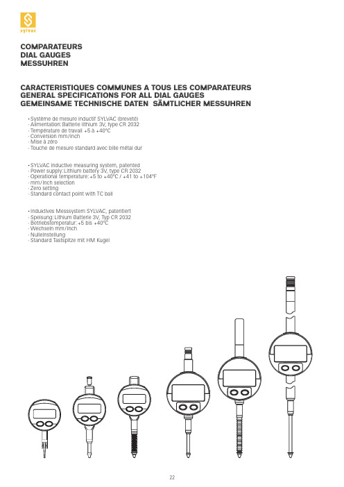
Les valeurs s’entendent à ±20%, comparateur en position verticale, tige de mesure sortante The values have to be understood ±20%, dial gauge in vertical position, outgoing spindle Die Werte verstehen sich ±20%, Messuhr in vertikaler Stellung, herausfahrender Messbolzen
Zero setting Mode absolut or relative mm/inch selection Input of preset value ≤ 130 Selection of measuring direction Simplex transmission
Nulleinstellung Absolut oder relativ Modus Wechseln mm/inch Vorwahlwert-Eingabe ≤ 130 Umkehrung der Messrichtung Simplex Übertragung
AOC液晶显示器用户说明书
安全说明 (4)关于本指南 (4)电源 (5)安装 (6)清洁 (8)其他 (9)安装 (10)标准配置 (10)安装支架底座 (11)调整视角 (12)连接显示器 (13)安装墙壁装配架 (14)调节显示器 (15)设置最佳分辨率 (15)Windows Vista (15)Windows XP (17)Windows ME/2000 (18)快捷键 (19)OSD 调节 (20)明亮度 (21)图像设置 (23)色温 (25)色彩增强 (27)窗口增亮 (29)OSD 设置 (31)其它 (33)重置 (35)退出 (37)LED 指示灯 (39)驱动 (40)显示器驱动 (40)Windows 2000 (40)Windows ME (40)Windows XP (41)Windows Vista (44)Windows 7 (46)i-Menu .............................................................................................................................................................. 51 故障排除 .. (54)规格 (56)主要规格 (56)e-Saver Screen+ ............................................................................................................................................................ 5.. (53)2即插即用 (59)安规信息 (60)FCC注意事项 (60)WEEE声明 (60)有毒有害物质或元素声明 (61)能效等级 (61)安全说明关于本指南下面说明本文档中使用的符号约定。
Dell Crystal 平板显示器用户手册说明书

前视图前面板控制1OSD 菜单按钮后视图侧视图左侧右侧底视图带显示器支架的底视图启动计算机和显示器以访问OSD。
注:本显示器符合 ENERGY STAR®(能源之星)规范。
下面显示了HDMI 接口的针脚分配:针脚19 针侧信号线的显示器侧针脚号码安全说明FCC联系警告返回内容页设置显示器Dell™ Crystal 平板显示器如果使用的是可以上网的Dell™ 台式机或Dell™ 便携式计算机1. 转到, 输入你的服务标签,然后下载用于你图形卡的最新驱动程序。
2. 安装图形适配器的驱动程序后,再尝试将分辨率设置 1680x1050 。
返回内容页注: 如果你不能将分辨率设置为 1680x1050,请联系 Dell™ 查询支持这些分辨率的图形适配器。
返回内容页设置显示器Dell™ Crystal 平板显示器如果使用的是非 Dell™ 台式机、便携式计算机或图形卡。
1. 右击桌面,然后单击属性。
2. 选择设置选项卡。
3. 选择高级。
4. 通过窗口顶部的描述,识别你的图形控制器提供商(如 NVIDIA, ATI, Intel 等)。
5. 请参阅图形卡提供商网站以取得更新的驱动程序(如, 或 )。
6. 安装图形适配器的驱动程序后,再尝试将分辨率设置 1680x1050 。
返回内容页注:如果你不能将分辨率设置为 1680x1050,请联系计算机的制造商或考虑购买支持 1680x1050 分辨率的图形适配器。
前面板按钮OSD 菜单向上向下OK电源DELL 标志指示)注您可以使用 與 按鈕做為存取喇叭音量捲軸列的捷徑,然後按下 按鈕來增加音量,按下 按鈕來降低音量。
注按 打开主菜单2.按 和 按钮切换菜单内的选项。
在您从一个图标移到另一个图标时,选项名称会被突出显示。
3.要选择菜单上突出显示的项目,请再按一下 。
按 和 按钮选择想要的参数。
按 按钮进入滑杆,然后按照菜单上的指示器使用 或按钮进行更改。
选择 返回上一菜单,而不接受当前设置,或者选择接受并返回上一菜单。
达威仪器有限公司产品说明:温度 过程控制器 Series 32B、16B、8B、4B说明书
Price
$84.00 37.00n
7.70n 20.00 137.00 255.00
MODEL CHART - 4B
Supply Power
4B-23
100-240 VAC
Supply Power Output 1
32B-23 100 to 240 VAC Voltage pulse
32B-23-LV 24 VDC
Voltage pulse
32B-33 100 to 240 VAC Relay
32B-33-LV 24 VDC
Relay
32B-53 100 to 240 VAC Current
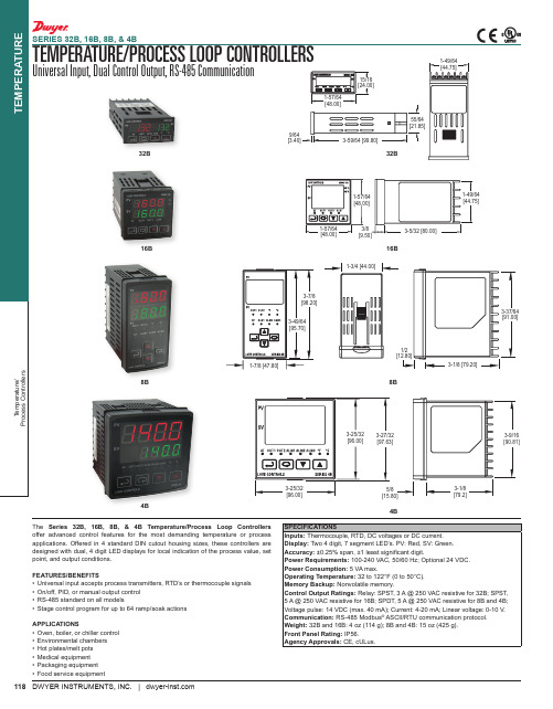
APPLICATIONS • Oven, boiler, or chiller control • Environmental chambers • Hot plates/melt pots • Medical equipment • Packaging equipment • Food service equipment
16B-23-LV 24 VDC
16B-33 100-240 VAC
16B-33-LV 24 VDC
16B-53 100-240 VAC
16B-53-LV 24 VDC
16B-63 100-240 VAC
16B-63-LV 24 VDC
Output 1
Output 2
Voltage pulse Relay
32B-53-LV 24 VDC
Current
Output 2 Relay Relay Relay Relay Relay Relay
无缝切换小间距全彩透明LED屏接收卡Armor系列诺瓦科技A4s参数设置说明书英文版

2Overview ......................................................................................................................................... 2
3Characteristics ................................................................................................................................ 3
4.3Indicator ....................................................................................................................................................... 7
4.4.3Reference Design for Expandable Interfaces ......................................................................................... 14
5Software Structure ...................................................................................................................... 16
FCC规定设备说明书

used in accordance with the instructions manual, may cause interference to radio communications. It has been tested an found to comply with limits for a Class A digital device pursuant to subpart J of Part 15 of FCC Rules, which are designed to provide reasonable protection against interference when operated in a commercial environment. Operation of this equipment in a residential area is likely to cause interference in which case the user at his own expense will be required to take whatever measures to correctany person other than the authorized technicians opens the machine. The user should consult his/her dealer for the problem happened. Warranty voids if the user does not follow the instructions in application of this merchandise. The manufacturer is by no means responsible for any damage or Posiflex has made every effort for the accuracy of the content in this manual. However,technical inaccuracies or editorial or other errors or omissions contained herein, nor for direct, indirect, incidental, consequential or otherwise damages, including without limitation loss of data or profits, resulting from the furnishing, performance, or use of this material.“as is” and Posiflex Technologies, Inc. expressly disclaims any warranties, expressed, implied or statutory, including without limitation implied warranties of merchantability or fitness for particular purpose, good title and The information in this manual contains only essential hardware concerns for general user and is subject to change without notice. Posiflex reserves the right to alter productBRIEF INTRODUCTIONTHE PRODUCTThe PD-309/ PD-2605 is a pole mount customer display option designed for Posiflex mini slim base of KS-2010 or DT-20X POS terminals. It is delivered in separate carton for the host system and shall be installed per instructions in this manual.FEATURES• LCD (Liquid crystal display) with dark blue character and yellowgreen back-light for PD-309• Bright VFD (vacuum fluorescent display) with green filter for PD-2605• Two-line display with 20 characters per line• Easy viewing characters (6.0 mm by 9.66 mm for PD-309 / 9.03mm by 5.25 mm for PD-2605)• Long life and trouble free operation• 15¢X, 30¢X and 45¢X adjustable viewing angles• Display frame can rotate horizontally 270° freely• Selectable command emulation modes including PST and EPSONcommand emulation modes for PD-309• Various command emulation modes selectable by DIP switch forPD-2605• Support 13 Code Pages of 128 characters each for PD-2605• Support 12 international character sets of 12 characters each forPD-2605• Simple installation• Selectable between Serial (RS232) interface model and USBinterface model• Supports UPOS 1.8 and is WEPOS ready for PD-2605metal base plate of the PD to bottom of mini slim base or DT-20X at the circled positions. For mini slim base Connect the interface cable to go into the base through at right to the main unit. For DT-20X arrange the interface cable to go through underbottom to connector area arrowed in Pix. 1 at above right.COMMAND EMULATION MODE SETUP (FOR PD-2605)Now please check the back of PD-2605 display head as in the above left picture in Pix. 3. There is a small piece of plastic cover for the “DIP switch window”. Slide the cover downward but don’t pull it off otherwise you may have to practice for inserting it back. You can find 6 positions ofDIP switch windowPix. 3Pix. 2Pix. 1SPECIFICATIONOPTICALNumber of digits 20 digits/row, 2 rowsDot matrix 5 X 7 dotsDigit height 9.66 mm (PD-309) / 9.03 mm (PD-2605) Digit width 6.0 mm (PD-309) / 5.25 mm (PD-2605) Display color Dark blue (PD-309) / Green (PD-2605)MECHANICALTotal Height 283 mmDisplay Head Height 57.5 mmDisplay Head Width 196.6 mmDisplay Head Depth 39.5 mmCase color BlackELECTRICAL。
JVC XA-GP3BK MP3音频导览系统用户指南说明书

New MP-3 audio guidance system makes tours fun and informativeCompact, durable, and easy-to-use, JVC’s new XA-GP3BK portable ROM player uses MPEG Layer 3 (MP3) compression and 44.1 kHz sampling to produce high-quality stereo sound that can include not only spoken voice narration and guidance, but music and sound effects as well. (Audio segments can be encoded at different bit rates.) Visitors will be able to get the most from their tour , while being free to view exhibits at their own pace.Designed to give you the flexibility you need to produce a customized audio tour specifically suited to your facilities, the XA-GP3BK’s default system settings — such as starting method,pause, auto power off, toggle play and message — can be adjusted as required. New extra-value features include numeric key input with sound for easy operation and confirmation even in the dark, pause capability during playback, and a power-saving auto power off function.Audio descriptions can be provided in up to 30 different languages with one-touch switching between languages. Already used in the Kennedy Space Center , JVC audio guidance system is ideal for museums, zoos, aquariums, factory tours, art galleries, and more.Audio Guidance SystemPortable ROM player XA-GP3BKPrinted in Japan SCU-9027Design and specifications subject to change without notice.Copyright ©2000, Victor Company of Japan, Limited (JVC). All Rights Reserved.DISTRIBUTED BY TEL: 973-315-5000, 1-800-526-5308 FAX: 973-315-503021 Finchdene Square, Scarborough Ontario M1X 1A7JVC PROFESSIONAL PRODUCTS COMPANYDIVISION OF JVC AMERICAS CORP.1700 Valley Road, Wayne, N.J. 07470JVC CANADA INC.TEL: 416-293-1311 FAX: 416-293-8208。
B-TIMER - Operating Instruction Manual
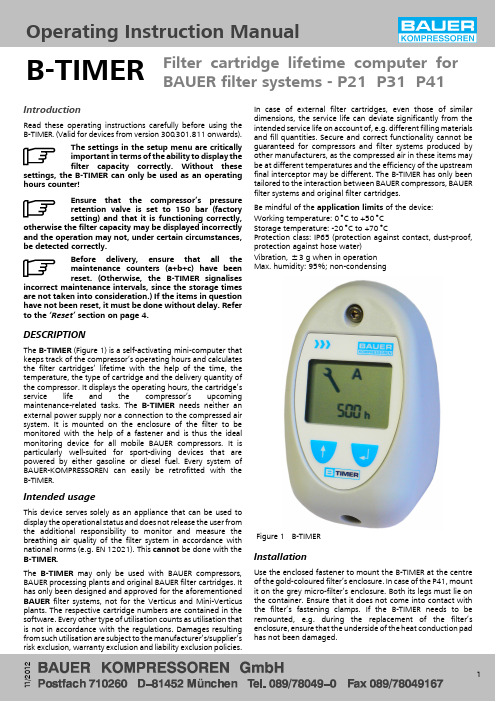
Filter cartridge lifetime computer for BAUER filter systems -P21P31P41Operating Instruction ManualB-TIMER11/20121IntroductionRead these operating instructions carefully before using the B-TIMER.(Valid for devices from version 300.301.811onwards).The settings in the setup menu are critically important in terms of the ability to display the filter capacity correctly.Without thesesettings,the B-TIMER can only be used as an operating hours counter!Ensure that the compressor’s pressure retention valve is set to 150bar (factory setting)and that it is functioning correctly,otherwise the filter capacity may be displayed incorrectly and the operation may not,under certain circumstances,be detected correctly.Before delivery,ensure that all the maintenance counters (a+b+c)have been reset.(Otherwise,the B-TIMER signalisesincorrect maintenance intervals,since the storage times are not taken into consideration.)If the items in question have not been reset,it must be done without delay.Refer to the ‘Reset’section on page 4.DESCRIPTIONThe B-TIMER (Figure 1)is a self-activating mini-computer that keeps track of the compressor’s operating hours and calculates the filter cartridges’lifetime with the help of the time,the temperature,the type of cartridge and the delivery quantity of the compressor.It displays the operating hours,the cartridge’s service life and the compressor’s upcoming maintenance-related tasks.The B-TIMER needs neither an external power supply nor a connection to the compressed air system.It is mounted on the enclosure of the filter to be monitored with the help of a fastener and is thus the ideal monitoring device for all mobile BAUER compressors.It is particularly well-suited for sport-diving devices that are powered by either gasoline or diesel fuel.Every system of BAUER-KOMPRESSOREN can easily be retrofitted with the B-TIMER.Intended usageThis device serves solely as an appliance that can be used to display the operational status and does not release the user from the additional responsibility to monitor and measure the breathing air quality of the filter system in accordance with national norms (e.g.EN 12021).This cannot be done with the B-TIMER.The B-TIMER may only be used with BAUER compressors,BAUER processing plants and original BAUER filter cartridges.It has only been designed and approved for the aforementioned BAUER filter systems,not for the Verticus and Mini-Verticus plants.The respective cartridge numbers are contained in the software.Every other type of utilisation counts as utilisation that is not in accordance with the regulations.Damages resulting from such utilisation are subject to the manufacturer’s/supplier’s risk exclusion,warranty exclusion and liability exclusion policies.In case of external filter cartridges,even those of similar dimensions,the service life can deviate significantly from the intended service life on account of,e.g.different filling materials and fill quantities.Secure and correct functionality cannot be guaranteed for compressors and filter systems produced by other manufacturers,as the compressed air in these items may be at different temperatures and the efficiency of the upstream final interceptor may be different.The B-TIMER has only been tailored to the interaction between BAUER compressors,BAUER filter systems and original filter cartridges.Be mindful of the application limits of the device:Working temperature:0︒C to +50︒C Storage temperature:-20︒C to +70︒CProtection class:IP65(protection against contact,dust-proof,protection against hose water)Vibration,±3g when in operation Max.humidity:95%;non-condensingFigure 1B-TIMERInstallationUse the enclosed fastener to mount the B-TIMER at the centre of the gold-coloured filter’s enclosure.In case of the P41,mount it on the grey micro-filter’s enclosure.Both its legs must lie on the container.Ensure that it does not come into contact with the filter’s fastening clamps.If the B-TIMER needs to be remounted, e.g.during the replacement of the filter’s enclosure,ensure that the underside of the heat conduction pad has not been damaged.Operating instruction manual -B-TIMER2Method of functioningThe B-TIMER display displays the following functions:∙Operating hours of the compressor plant.A blinking ‘h’indicates that the compressor-operation has been detected.∙Cartridge life in %via 4segments in the filter-cartridge symbol.∙When the remaining capacity reaches or falls below 20%of the total lifetime,the final segment starts blinking and the figure displayed for the operating hours switches over to the cartridge’s order number.∙The compressor plant displays the upcoming maintenance-related tasks with the help of alphabets and figures displaying the operating hours.A =500hours or 1year B =1000hours or 2years C =2000hours or 4years∙A battery symbol is used to indicate that the lithium battery is weak and must be replaced.The data is saved and is not lost when the battery is changed.The B-TIMER is operated with the help of the entry and selection keys.Error displayIf the temperature sensor in the device malfunctions,‘Error 1’or ‘Error 2’comes up at the display (Figure 3).In such a case,use of the B-TIMER should be discontinued.Send the device to the factory for repairs,or send it to the next agency.Battery replacementThe battery (1,Figure 4)is placed in the battery compartment.To replace the order,withdraw plug (2)and pull the battery out of the battery compartment.Make sure you use a battery of the same type (BAUER order number82743).Figure 2Display 12345671Key symbol (maintenance due)2Alphabet (type of maintenance)3Battery symbol4Cartridge saturation display5Operating hours or cartridge no.6Selection keys 7Entry keysFigure312Figure 4Battery replacementOperating instruction manual -B-TIMER3OperationThe B-TIMER switches itself on when the compressor is activated.The fact that the compressor is in operation is indicated by the blinking ‘h’symbol.To switch on the B-TIMER without putting the compressor into operation,press one of the buttons on the display:the main menu is displayed (Figure 5).If no button is actuated for 1minute,the display reverts to the main menu.The B-TIMER switches itself off if thecompressor-operation is not detected in 2minutes.Functional displayPress the selection button to display the desired function (↑).Press the ↑button.The remaining filter-capacity is displayed (Figure 6).Press the ↑button.The number of operating hours lying between the point in question and service interval A (500hours or yearly)is displayed (Figure 7).Press the ↑button.The number of hours remaining before service interval B (1000hours or every two years)is displayed (Figure 8).Press the ↑button.The number of hours remaining before service interval C (2000hours or every four years)is displayed (Figure 9).Press the ↑button.The filter-cartridge number is displayed (Figure 10).The filter icon blinks.Press the ↑button.The display reverts to the main menu.Figure5Figure6Figure7Figure8Figure9Operating instruction manual -B-TIMER4ResetThe filter capacity may only be reset after the cartridge has been replaced!To reset the filter capacity or the A,B and C service intervals,hold the ↵ button down for more than 5seconds when the respective display has been activated (Figure 11).SetupTo navigate to the setup menu of the various functions of the B-TIMER ,hold down the ↑and ↵ buttons simultaneously for more than 5seconds when the cartridge number is being displayed (Figure 10).The filter icon starts blinking (Figure 12),which indicates the setup mode.The applicable filter-cartridge no.is set under setup A .To change the article number,hold down the ↵ button for 3seconds,after which the number starts e the ↑button to set the desired e the ↵ button to accept the number in question.Article numbers beginning with 999must be set in a special manner.Hold down the ↵ button for 3seconds,and then enter 999000with ↑.The last 0starts blinking.Appoint the corresponding digit with ↑and accept it with ↵.When the 2nd zero starts blinking,appoint the digit as described above,and carry out the same procedure for the 3rd digit.When the ↑button is pressed,the display switches over to setup B (setting of the delivery quantity).The filter icon starts blinking (Figure 13).The delivery quantity (in l/min.)can be found in the compressor’s instruction manual.To change the configuration,hold down the ↵ button for 3seconds,after which the 1st digit starts e the ↑button to set the desired e the ↵ button to accept the number in question and repeat the same procedure until all three digits have been set correctly.When the ↑button is pressed again,the display switches over to setup C (setting of operating pressure).The filter icon starts blinking (Figure 14).To change the operating pressure,hold down the ↵ button for more than 3seconds.Press the ↑button to enter the new operating pressure.(Options:200bar,300bar or 200/300bar).Press the ↵button to confirm the new setup.The filter capacity must be reset after the setup preferences have been entered and a new filter cartridge has been inserted.Refer to the ‘Reset’section.When the ↑button is pressed again,the display switches over to the setup menu for the operating hours .Press the ↵ button for 2seconds,after which the last digit starts e the ↑button to appoint the desired digit and press the ↵ button.Repeat this procedure until all the digits have been entered.Repeated actuation of the ↑button leads the system back to the main menu.Pressing the ↑and ↵ buttons (for 2seconds)makes it possible to repeat the setup procedure.Figure10Figure11Figure12Figure13Figure14。
穆迪AC漏电流测试仪CMP-200操作手册说明书

MINI AC LEAKAGE CURRENTMETERCMP-200Version 1.7The CMP-200 digital clamp meter has been designed for the purpose of clamp measurements of alternative leakage current. Main features of the CMP-200 device are the following:•high resolution up to 0,1mA AC,•auto power off,•3½ digits display,•white LED backlight,•1,2” jaw diameter,•safe, protected clamp jaws,•double molded housing.2TABLE OF CONTENTS1INTRODUCTION (4)2SAFETY (5)3PREPARATION OF THE TESTER FOROPERATION (6)4FUNCTIONAL DESCRIPTION (7)5MEASUREMENTS (9)5.1AC CURRENT MEASUREMENTS (9)5.2DATA HOLD F UNCTION (10)5.3B ACKLIGHT DISPLAY (10)5.4DATA MAX HOLD F UNCTION (10)6REPLACEMENT OF THE BATTERIES (11)7CLEANING AND MAINTENANCE (11)8STORAGE (11)9DISMANTLING AND UTILIZATION (11)10ATTACHMENTS (12)10.1T ECHNICAL DATA (12)10.2S TANDARD EQUIPMENT (13)10.3M ANUFACTURER (13)31 IntroductionWe appreciate your having purchased our digital clamp AC leakage current tester. The CMP-200 meter is a modern, high-quality measuring device, which is easy and safe to use. Please acquaint yourself with the present manual in order to avoid measur-ing errors and prevent possible problems related to operation of the tester.In the present manual we apply three kinds of warnings. These are texts in frames, which describe possible dangers both for the user and the tester itself. The messages starting from the word ‘WARNING:’ describe situations which imply a risk for life or health should the recommendations presented in the present manual not be observed. The word ‘ATTENTION!’ introduces a description of a situation where non-observance of the recommendations presented in the present manual may imply damage for the tester. Indications of possible problems are preceded by the word ‘Attention:’.WARNING:Before using the instrument acquaint yourself with the pre-sent manual and observe the safety regulations and recom-mendations specified by the manufacturer.WARNING:The purpose of the CMP-200 tester is to realise clamp meas-urements of the leakage current. Using the tester in a man-ner which does not comply with the recommendations speci-fied in the present manual may lead to its damage and con-stitutes a source of a serious risk for the user.4The CMP-200 tester may be operated solely by qualified and properly authorised personnel for work at electric installa-tions. Using the tester by unauthorised personnel may lead to its damage and constitutes a source of a serious risk for the user.2 SafetyIn order to guarantee proper operation and correctness of the ob-tained results it is necessary to observe the following recommenda-tions:•Before commencing operation of the tester please acquaint yourself thoroughly with the present manual,•The instrument should be operated solely by properly qualified personnel, who also must be trained regarding the industrial safety regulations,•Use great care when making measurements if the voltages are greater than 25V AC rms or 35V DC. These voltages are consi-dered a shock hazard,•Set function switch to the appropriate position before measur-ing,•Do not exceed the maximum allowable input range,•It is prohibited to operated the tester:⇒If it is damaged and completely or partially out of order⇒If it has been stored for an excessive period of time in inad-equate conditions (e.g. if it is humid)•Repairs must be realised solely by an authorised service work-shopWARNING:Do not realise measurements with wet hands.5Do not realise measurements in environments in which there are inflammable gases. Otherwise operation of the tester under such conditions may cause sparking and explosion.3 Preparation of the tester for operationHaving purchased the tester examine completeness of the con-tents of the package.Before measurements commence, it is necessary to realise the following actions:•Make sure the conditions of the batteries or accumulators per-mit to realise measurements,•Make sure the casing of the tester is not damaged.64 Functional description2ALEAKAGE CURRENT TESTER MAX HOLDCMP-20071 current clamp2 rotational selector•OFF – tester off•200mA, 2A, 200A–measurement ranges 3 HOLD button•Data Hold function•Back Light function4 LCD display5 clamp trigger6 data MAX hold function85 Measurements5.1 AC current measurementsWARNING:Do not take current readings on circuits where the maximum current potential is not known. Do not exceed the maximum allowable input range while measuring current.WARNING:Do not realise measurements if the battery compartment is open.In order to realise a measurement of alternative current, it is necessary to realise the following actions:•Set the Function switch to desired range, if the range of the measured is not known, select the highest range first, •open the clamp and place it properly on a cable•read the result of the measurement on the display,•move to the lower range if necessary.Attention:During measurements of the current make sure the clamp is properly placed. Otherwise the results of the measurements will not be exact. The most exact result we will get if the wire is placed in the middle of clamp.Refer to the diagrams below for examples of the tester’s appli-cations9to normal operation, press the “Hold Backlight” key again. The word HOLD will switch off.5.3 Backlight displayPress and hold the HOLD button key for more than 2 seconds to turn on the backlight. This will also activate the Data Hold function. To release the Data Hold function and return the tester to normal operation, press the HOLD button momentarily. To turn off the backlight, press and hold the HOLD button for more than 2 seconds.5.4 DATA MAX HOLD FunctionTo freeze the max reading on the LCD, press the MAX button. The word MAX will appear on the LCD while the tester is in the Max hold mode. To release the tester to normal operation, press the MAX button.106 Replacement of the batteriesThe CMP-200 tester is supplied by means of two 1.5V AAA bat-teries. It is recommended to use alkaline batteriesAttention:When making measurements with a battery's mnemonic on, one must take into account additional indefinite measure-ment uncertainty or unstable working of the meter.In order to replace the battery it is necessary to do the following: •place rotational selector in the position OFF and remove the one rear Phillips head screw,•open the battery compartment and replace the required two1.5V AAA batteries,•re-assemble the tester.7 Cleaning and maintenanceThe casing of the tester may be cleaned with a soft, damp cloth using all-purpose detergents. Do not use any solvents or cleaning agents which might scratch the casing (powders, pastes, etc.).The electronic system of the tester does not require maintenance.8 StorageIn the case of storage of the device, the following recommenda-tions must be observed:•Make sure the tester and its accessories are dry,•In the case the tester is to be stored for a prolonged period of time, the battery must be removed from the device.9 Dismantling and utilizationWorn-out electric and electronic equipment should be gathered selectively, i.e. it must not be placed with waste of another kind.11Worn-out electronic equipment should be sent to a collection point in accordance with the law of worn-out electric and electronic equipment.Before the equipment is sent to a collection point, do not dis-mantle any elements.Observe the local regulations concerning disposal of packages, worn-out batteries and accumulators.10 Attachments10.1 Technical data•The …m.v.” means the measured value of standard.AC current measurementRange Resolution Basic uncertainty199,9mA 0,1mA ±(5% m.v. + 8 digits)1,999A 0,001A ±(5% m.v. + 10 digits)199,9A 0,1A ±(2,5% m.v. + 10 digits) •frequency range 45...65HzOther technical dataa) Measurement category in acc. with EN 61010-1:2004 .....II 600Vb) Ingress protection in acc. with PN-EN 60529 ...................... IP40c) Pollution degree (2)d) Power supply ..........................................two 1.5V AAA batteriese) Clamp size.............................................................. 30mm (1,2")f) Overrange indication.............................................. OL displayedg) Display rate ..................................... 2 readings/second, nominalh) Display ............................................. L CD, 3½ digit (1999 count)i) Dimensions ..................................................... 182 x 61 x 34 mm j) Weigh (including batteries) ................................................ 225 g k) Operating temperature and humidity ...................................................................................... 0ºC to 30ºC (32ºF to 86ºF) max 90% 12....................................... 30ºC to 40ºC (86ºF to 104ºF) max 75% ..................................... 40ºC to 50ºC (104ºF to 122ºF) max 45% l) Storage temperature and humidity ..........................................................................................-20 to 60°C (-4 to 140°F) max 80% m) Max. operating altitude .................................... 3000m (10000ft.) n) Auto OFF ...................................................... a pprox. 15 minutes o) Compliance with the requirements specified in the following norms ............................................................. EN 61010-1:2004 ............................................................................... EN 61010-2-032 p) Quality standard .......................................................... I SO 9001 10.2 Standard equipmentThe standard set provided by the manufacturer includes the fol-lowing components:•The CMP-200 tester,• 1.5V AAA battery (2 pieces),•Operating manual,•Warranty card.10.3 ManufacturerThe manufacturer of the device, which also provides guarantee and post-guarantee service is the following company:SONEL S. A.ul. Wokulskiego 1158-100 ŚwidnicaTel: +48 74 858 38 60Fax: +48 74 858 38 09E-mail: ***************Web page: www.sonel.plNote:Service repairs must be realised solely by the manufactur-er.Made in China for SONEL S.A.13。
Catalog_Electrical

0-400A/4000A/40mA/400mA/10ADC
o AC Current:
0-400A/4000A/40mA/400mA/10AAC
o Resistance: 0-400/4k/40k/400k/4M/40M⍀ o Frequency: 10-4k/40k/400kHz o Tach:
ELECTRICAL
AMP Clamps
FEATURES DELUXE DIGITAL AMP CLAMP METER
Plant Maintenance, HVAC/R. • 10 Functions - 34 Ranges • Backlight and jaw light • 1,000 amps AC • Measures frequency, temperature and capacitance • Data hold and rel. mode • Diode test and continuity beeper • Manual or auto ranging • Jumbo 4 digit display • Low battery indicator
o Current: 0-600A AC/DC o Power Source: 1 “9V” battery (included)
UPC NO.
10014 1
DAMP3500 DAMP3500
AUTOMOTIVE METER/AUTOMOTIVE KIT
AC/DC Current readings. • 12 Functions - 39 Ranges • Great for Automotive use • Bar graph display • 10 M⍀ input Impedance • Auto Power Off
Timecode Systems wave 快速上手指南说明书
For the latest manual please visit:sync for sound/support/product-manualsHere we give you a quick tour of your new Timecode Systems :wave, guiding you through its key features so you can get up and running straight away.What’s covered?The basics to getting started with:• Timecode Systems: :wave• Overview of the BLINK network protocol• The Timecode Systems BLINK Hub app (free to download)Y our Timecode revolution starts here...1.AntennaFor the digital transceiver module operating in 868MHz to 923MHz ISM bands.2. LEDGlows either blue, green or red.• Blue flash - Wi-Fi ON• Green flash- Wi-Fi OFF• Red flash - Warning messages3.OLED displayShows the unit's status and settings.4.Control knobAllows one finger navigation through menus.5.Mounting threadsChoose from 3/8" UNC or 1/4" UNC mounting options.This is a guided tour of the :wave. Your highly accurate timecode, word clock& genlock generator and multi-channel digital timecode transciever. Alsowith simultaneous Wi-Fi.ControlThe Timecode Systems: :wave settings are accessed and controlled fromthe top panel. This handy position gives you full and easy control of the unit even when it's in a sound mixer bag or sound cart.5 Mounting threads4 Control Knob3 OLED Display 2 LED1 AntennaPortsFor all power and sync ports go to the back and side panels of the device.1. 9-36V DC: LEMO2 socket. Power input.2. DATA: LEMO9 socket. For connectivity to third party equipment.3. TC: LEMO5 socket.TC IN and TC OUT.4. TC/SYNC:BNC Socket (select menu for either L TC OUT, Word ClockOUT or TV SYNC OUT)5. Micro USB 2.0 Socket,5V power IN. Firmware Updates via theTimecode Systems PC and Mac USB Updater Applications.Please visit /support/firmware for instructionson how to update the firmware of your :wave product.15234Mounting SolutionsThe :wave has flexiblemounting options.optional extrasTimecode Systemshot shoe adaptor TCB-34 7" articulated mounting armkit TCB-32CustomiseOn-screen menus allow you to easily customise the settings of the Timecode Systems :wave to meet the exact needs of your shoot.The default display shows (on time-out also):TC + Unit Name (if assigned by app) + MODE + RF CHANNEL+ SIGNAL STRENGTH+BATTERY STATUST urning the knob on the front panel clockwise takes you to the following information screens:1. TC, Unit Name, Mode, RF Channel, Signal strength, Battery status2. TC, User Bits, FPS3. BNC Sync 0/P Mode and Level4. Button Lock5. Power Status and Battery Status6. WI-FI Network Mode, Status, IP Address, SSID name7. Product name, FW version, Serial numberButton basicsPress the knob to enter the menu for:1. TC Generator2. SYNC Generator3. Set RF Channel number (if in an RF mode)4. Wi-Fi Settings5. Display Settings6. System Settings7. Timecode ModeMore on menusEach menu allows further customisation of your Timecode Systems:wave Timecode Mode. Choose from five settings:• Free Run/Jam-Ext.This is a straightforward mode for a standard 'setand forget' sync box. No RF Timecode modes, just set the internalgenerator or jam T/C from an External source. The unit will 'Free-Run'.• lnt-Gen TX. This is a mode where the unit is the 'master clock', transmitting T/C to all receiving 'slave' devices. The unit acts as a BLINK master device, collecting all status and metadata from listening BLINK slave devices.• Ext-TC TX. This is a mode where the unit takes its T/C from an External source (via LEMOS connector), then transmits this T/C to all receiving 'slave' devices. The unit acts as a BLINK master device, collecting all status and metadata from listening BLINK slave devices.If the External T/C is removed the T/C ouput freezes.• Ext-TC/C TX. This is a mode where the unit takes its T/C from an External source (via LEMOS connector), then transmits this T/C to all receiving 'slave' devices. The unit acts as a BLINK master device. collecting all status and metadata from listening BLINK slave devices.If the External T/C is removed the T/C output continues using theInternal Generator.• Ext-RF Slave.This is a mode where the unit acts as a 'slave' receiving unit, constantly locking to the incoming RF timecode & sync data, soft jamming & chasing the incoming T/C from an RF master unit. Thiscould be Free Run or Rec-Run timecode. The units also acts as a BLINK slave unit, sending its status and settings back to the BLINK master unit.It can also be remotely controlled from the BLINK master unit viathe app.TC Generator. Choose from:• Set T/C. T urn to set flashing digits, press to enter. Repeat for each pair.• Set U/B. T urn to set flashing digits, press to enter. Repeat for each pair.• Set FPS. Set to 23.976, 24, , 25, 29.97, 29.97DF, 30 or 30DF. SYNC Generator. Choose from:• Set BNC O/P Mode. Choose from either Bi Level, T ri Level, Word Clock and L TC modes from this socket.• Set BNC O/P Level. Choose from NORMAL or HIGH levels.L TC needs to be set to HIGH. TV Sync can be selected toNORMAL or HIGH (3D Rigs). Word Clock is always set to HIGH.Set RF Channel Number: Select the RF channel group for T ransmit or Receive (depending on the timecode mode selected from the menu).Wi-Fi Settings. Unlocks Wi-Fi enabled features including wireless streaming of timecode to Timecode Systems BLINK Hub app, Adobe LiveLogger app, MovieSlate 8 logging app, Q T ake HD and Softron Movie Recorder. Also unlocks the powerful BLINK network features (see page 7).• Turn On/Off.When ON allows you to restart the Wi-Fi network if needed.• Network Type. Select 'Soft AP' for normal app connection(iOS, Android and MacOS) and viewing of the web interface.Select 'Infrastructure' to connect to an existing known Wi-Finetwork to extend Wi-Fi range (select the network to choosevia the BLINK Hub app interface)• Stealth Mode.Select this mode as a battery saving feature. IfExternal Power is removed, the :wave will automatically shutdown theWi-Fi network. As soon as the External Power is re-applied then theWi-Fi network is automatically switched back on.• Network ID No. Give your :wave its own SSID name* (Choose a number from 001 to 099). *Every :wave on set needs to be given a differentSSID to avoid network clashes.Display Settings:• Set Brightness. Allows you to change the level of brightness from 1through to 100. (100 being the brightest)• Power Saver Short. Stays bright short duration, then dims.• Power Saver Long. Stays bright longer duration, then dims.• Screensaver. The display will switch off after a period & switch onwith a button change.•Set Aiways ON. Stays bright at the set Brightness level.System Settings.• Set RF country/area. Set to Europe/UK, US/CA/AU/NZ or Japan.• Restore defaults. T o remove any customisation.• Set passcode. Choose a passcode to allow access to settings changes from Timecode Systens BLINK Hub app or MovieSiate 8 app. Default passcode is1111.BLINK Network FeatureThe BLINK network augments the existing wirelessly shared timecode and sync data. The proprietary BLINK RF network keeps the same incredibly accurate wireless sync over the robust sub GHz ISM bands, but adds enhanced two-way multiplexed status/control and metadata.This allows for complete monitoringand control of all connected“BLINK enabled” Timecode Sys-tems’ devices and is built to allowfor long-range remote control andstatus monitoring of any supported& connected third-party devices.The :pulse and :wave can be config-ured either as a BLINK master orslave, whereas the :minitrx+ andSyncBac PRO can only be configuredas BLINK slave devices.More on BLINKThe BLINK slave devices are continually feeding back their status and settings to the BLINK master unit. The BLINK master unit then allows the Timecode Systems BLINK Hub app to not only display all of this information, but allow the user to remote control certain features.Additionally with the :wave, if any supported 3rd party equipment is con-nected to the Data port, then this equipment can also be remotely con-trolled using the unit’s Wi-Fi interface to our BLINK Hub application or the MovieSlate 8 iOS app.All of this BLINK functionality is multiplexed with the original timecode and Sync information data packets. This ensures that legacy and non- BLINK enabled Timecode Systems’ devices are still supported from a BLINK master source.The huge advantage of the BLINK protocol is that the Timecode Systems RF transceiver is very long range and robust, with up to 500 metres line of sight range. It is a very uncongested frequency band on set and in heavy RF environments.This then allows the Wi-Fi network of the BLINK master to be used as a short wireless hop into the apps, with the long range communications to slave units being looked after by the BLINK network.Timecode Systems BLINK Hub appNow your Timecode Systems :wave hardware is up and running,it's time to download the Timecode Systems BLINK Hub app.• Our iOS app is free to download from the Apple app storeand the Android app is free to download from the Google Play store• Our MacOS app is free to download from our website• T urn on the Wi-Fi of your Timecode Systems :wave.• Select the Wi-Fi network of the Timecode Systems :wave – i.e. Wave095•Open the BLINK Hub app. This should now show the running timecode from your Timecode Systems :wave. The BLINK Hub data will be loaded from the :wave into the app.If you want to remotely change any of the Device settings via the app,press settings, type in the four-digit passcode (set on the systems menu of your Device) then make changes directly from the app (defaultpasscode: 1111). Without entering the password only the status on theunits can be viewed.Using the appOverview. The app allows you to display a frame accurate Timecode Readerof your timecode on set on the iOS or Android app via the Wi-Fi network.It also allows full remote control of settings of the :wave unit itself and anyconnected BLINK slave unit.1.Control PanelThis panel allows you to access all of the relevant controls for a selectedunit within the BLINK Hub. Change any of the available settings to have it immediatley update your device.2. Timecode ReaderA frame accurate timecode reader listing your running timecode andboth your userbits and framerate. T ap to expand into a full digital slateview.3.Status PanelLive status monitoring of any units on your BLINK network, view yourmaster and every other individual slave at a glance. Select a tile toaccess a device’s individual controls.4.Transport ControlUse our BLINK Protocol to communicate with any supported third partydevice attatched. Send transport control commands or open up a unique settings window to handle the more advanced options available.1324Detailed specificationsTimecode Systems::waveWi-Fi activated featuresAccurate Wi-Fi streaming of SMPTE timecode data to iOS and Android apps.Wi-Fi connectivity to allow setting changes to the :wave unit or any BLINKconnected remote slave RF connected unit.Wi-Fi connectivity to see all settings via any connected web browser.Infrastructure Wi-Fi connectivity to allow for multiple units to be connected toan external Access Point/Router (needs the BLINK Hub app to scan and join other networks) Wi-Fi connectivity to allow 2 way communications with supported 3rd partyequipment connected to the LEMO 9 DATA PORT. For example,if a 6 series Sound Devices audio recorder is connected via the TCB-40Interface cable to the keyboard USB port of the mixer then the 6-seriescan be fully remote controlled by the MovieSlate 8 iOS app and theBLINK Hub iOS, Android and MacOS apps.T echnical specificationExternal dimensions: 94mm x 67mm x 23mmOLED Display:Blue 128 x 32 pixelsTimecode generator accuracy:TCXO 0.1ppm when free running, in practicearound 0.1-0.2 frames drift in 24 hours. Zero ppm when RF locked to a master. Supported FPS Modes: 23.976, 24. 25. 29.97, 30, 29.97DF. 30DF.Supported SYNC Outputs :PAL, NTSC, 720p, 720p2 (double frame rate),1080i-PSF. 1080p, 1080p2, Word Clock standards 44.1, 88.2, 48. 96 and192KHzWi-Fi: 2.4 GHz IEEE std.802.11b/g, SoftAP and Infrastructure modes. DHCPServer, Web server.Timecode Systems::wavePower and timecode sources• External power: 2 pin LEMO (9V to 36V DC).• External power: Micro USB (5V DC).• Internal power: Built in Li-Polymer (3.7V battery)• T/C input: LEMO5• T/C outputs: LEMO5, LEM09 and BNC Socket• SYNC output: BNC Socket (TV SYNC, Word Clock or L TC)• Multi-channel digitaltransceiver: 865.050-868.550 MHz (CE Approved) 915.050-918.650 MHz (FCC/ICApproved) and920.600-923.200MHz (Japan ARIB Approved).FrequenciesTimecode Systems: :wave RF Frequencies, FHSSOur CE approved products are for use in UK/EU and CEPT* countries.*Albania, Andorra, Austria, Azerbaijan, Belarus, Belgium,Bosnia-Herzegovina, Bulgaria, Croatia, Cyprus, Czech Republic, Denmark, Estonia, Finland, France, Georgia, Germany, Greece, Hungary, Iceland, Ireland, Italy, Latvia, Liechtenstein, Lithuania, Luxembourg, Malta, Moldova, Monaco, Montenegro, Netherlands, Norway, Poland, Portugal, The Former Yugoslav Republic of Macedonia (FYROM), Romania, Russian Federation, San Marino, Serbia, Slovakia, Slovenia, Spain, Sweden, Switzerland, T urkey, Ukraine, United Kingdom, Vatican.• UK/EU 865.050 MHz to 868.550 MHz FHSSTimecode Systems: :wave RF Frequencies, FHSSOur FCC frequencies are for use in the USA, Canada, Australia and New Zealand.• USA/AU/NZ 915.050 MHz to 918.350 MHz FHSSTimecode Systems: :wave RF Frequencies, Fixed Our ARIB frequencies are for use in Japan.1 JP 920.600 MHz2 JP 920.800 MHz3 JP 921.000 MHz4 JP 921.200 MHz5 JP 921.400 MHz6 JP 921.600 MHz7 JP 921.800 MHz8 JP 922.000 MHz9 JP 922.200 MHz10 JP 922.400 MHz11 JP 922.600 MHz12 JP 922.800 MHz13 JP 923.000 MHz14 JP 923.200 MHzQuality declarationsFCC Warning Statement:This device complies with Part 15 of the FCC Rules.Operation is subject to the following two conditions:(1)This device may not cause harmful interference, and(2)This device must accept any interference received, including interference that may cause undesired operation.This equipment complies with FCC radiation exposure limits set forth for an uncontrolled environment. End users must follow the specific operating instructions for satisfying RF exposure compliance. This transmitter must not be co-located or operating in conjunction with any other antenna or transmit-ter.Changes or modifications not expressly approved by the party responsible for compliance could void the user's authority to operate the equipment. Industry Canada StatementsThis product contains radio transmitter 104271-TCB11 and AYV-TCB11. It has been approved by Industry Canada & FCC to operate with the antenna types listed below with the maximum permissible gain and required antenna imped-ance for each antenna type indicated. Antenna types not included in this list, having a gain greater than the maximum gain indicated for that type, are strictly prohibited for use with this device.Name: T aoglas TG.09.0113, 2.0dBi, 50 ohmThis device complies with Industry Canada licence-exempt RSS standard(s). Operation is subject to the following two conditions: (1) This device may not cause interference, and (2) This device must accept any interference, including interference that may cause undesired operation of the device.Under Industry Canada regulations, this radio transmitter may only operate using an antenna of a type and maximum (or lesser) gain approved for the transmitter by Industry Canada. T o reduce potential radio interference to other users, the antenna type and its gain should be so chosen that the equivalent isotropically radiated power (e.i.r.p.) is not more than that necessary for suc-cessful communication.CE Conformity Statement:Declaration of ConformityAccording to 150/IEC Guide 22. is in conformity with:-EN 60950-1:2006 + A11:2009+A1:2010+A12:2011+AC:2011-EN 300 440-1V1.6.1-EN 300 440-2 V1.4.1-EN 301489-1V1.9.2-EN 301489-3 V1.4.1Warranty and technical supportAll products sold by TIMECODE SYSTEMS LIMITED. are warranted to the original purchaser against defects in materials and workmanship for (1) year from the date of original purchase.However, this warranty excludes accessories, batteries and cables. Also, this warranty does not apply to any instrument determined byTIMECODE SYSYTEMS LIMITED to have been subjected to customer alteration, modification, negligence or misuse.In the event of any defects determined to be covered by this warranty, TIMECODE SYSTEMS LIMITED will, at its sole option, repair or replace the defective instrument without charge. T o obtain warranty service the defective instrument must be returned within one (1) year from purchase to: TIMECODE SYSTEMS LIMITEDATTN: Repair DepartmentUnit 6, Elgar Business CentreMoseley Road, HallowWorcester, WR2 6NJ, UKT elephone +44 (0) 1700 808 600All transportation and shipping costs are the responsibility of the purchaser./support/product-manuals For the latest manual please visit:。
- 1、下载文档前请自行甄别文档内容的完整性,平台不提供额外的编辑、内容补充、找答案等附加服务。
- 2、"仅部分预览"的文档,不可在线预览部分如存在完整性等问题,可反馈申请退款(可完整预览的文档不适用该条件!)。
- 3、如文档侵犯您的权益,请联系客服反馈,我们会尽快为您处理(人工客服工作时间:9:00-18:30)。
FeaturesThe DMS-30PC Series is a broad line of self-contained, fully operational, 3½digit voltmeters with large, easy-to-read LED displays. The 0.56"(14.2mm) high LED's are available in a wide variety of colors including red, orange, amber, yellow,green, aqua, blue-green, and super-blue. A high-intensity version of the red display is optional, as are low-power versions of the red, orange, and green displays.The small size (2.17" x 0.92" x 0.56") of DMS-30PC meters is achieved byintegrating their display, display drivers, reference circuit, and A/D converter into in a single, epoxy-encapsulated assembly. The device's 12-pin, component-like, DIP package is both vibration and moisture proof. Each package incorporates a built-in color filter and bezel and is easily mounted in either panels or pc cards.These meters are available in four differential input voltage ranges (±200mV,±2V, ±20V and ±200V). Input impedance is 1,000 megohms for the ±200mV and ±2V inputs and 1 megohm for the ±20V and ±200V inputs. CMRR for all devices is 86dB, and inputs are overvoltage protected to ±250V.Each meter incorporates an extremely stable, double-regulated reference and is fully calibrated prior to potting. We guarantee outstanding initial accuracy (±1 count)and excellent stability (±0.15 counts/°C). All models operate from a single +5V supply, and the low-power models draw as little as 10mA (50mW total power). A DISPLAY TEST function is standard on each device.For popular applications (4-to-20mA, rms-to-dc conversion, ac line power, J and K thermocouples, etc.), the DMS-30PC Series includes a complete line of optional "plug-on" application boards that conveniently convert your meter into an applica-tion-specific instrument.•Large (0.56"/14.2mm) LED display •8 LED colors•Low-power LED’s optional•Epoxy-encapsulated, 12-pin DIP with built-in color filter and bezel •Miniature size:2.17" x 0.92" x 0.56"55mm x 23mm x 14mm •Panel or pc-board mountable •4 differential input voltage ranges •Auto-calibration, ±1 count accuracy •User-selectable decimal point placement •Single +5V supply (60mW for low-power models)•0 to +60°C temperature range•Numerous "plug-on" application boards •Low costActual Size3½ Digit, LED Display Low-Power, Miniature Digital Panel VoltmetersDMS-30PC SeriesNEW!Super-Bright Blueand Blue-Green LED ModelsPerformance/Functional SpecificationsTypical at T A = +25°C and supply voltage = +5V using the single-ended input circuit,unless otherwise noted.DMS-30PC -1 -R SLED Color:AS = Standard Amber BS = Super Blue GS = Standard Green OS = Standard Orange QS = Standard Aqua RS = Standard Red YS = Standard Yellow RH = High-Intensity Red GL = Low-Power Green OL = Low-Power Orange RL = Low-Power Red VFS = Blue-GreenTechnical Notes1.+1.23V REFERENCE OUTPUT (Pin 9): This pin is the output of the meter’s precision +1.23V internal reference, and it is referenced to ANALOG COMMON (pin 10) which sits at a potential of approxi-mately +2V. This output should be buffered if used to drive external loads since sourcing more than 15µA from pin 9 can affect both the initial accuracy and temperature drift of the meter.2.ANALOG COMMON (Pin 10): This pin is connected to an internal,low-noise, "relative" ground. It is used in certain differential and "floating" measurements as described in the Applications section of this data sheet and Ap Note 3 of the DATEL Panel Meter Catalog.Pin 10 should not be connected to pin 3 (5V RETURN) or to your system’s analog ground.3.REFERENCE OUTPUT (Pin 8) and INPUT (Pin 7): Pin 8 is a precision reference actively trimmed at the factory. In normal operation, pin 8 must be tied to pin 7 to achieve all listed accuracy and drift specifications.Accessories:DMS-PS1-CM +5V/1.0A AC/DC power supply module DMS-30-CP Panel cutout punch DMS-BZL1DMS-30 bezel assemblyDMS-BZL2DMS-30 bezel assembly with sealing gasket RN-DMSGain/offset potentiometer kit for DMS-EB,DMS-EB-AC/DC and DMS-EB-DC/DCAdd-On Application Boards:DMS-EB Multi-purpose (gain/offset, 4-20mA, etc.)DMS-EB-HTB High-accuracy temperature probe sensing for±200mV modelsDMS-EB-DC/DC Provides isolated +5V power DMS-EB-TCJ J-type thermocouple inputs for ±2V models DMS-EB-TCK K-type thermocouple inputs for ±2V models DMS-EB-RMS For true rms measurements of ac voltages DMS-EB-AC/DC For ac line-powered applications DMS-EB-LP For 4-to-20mA loop-powered applications Input Range:0 = ±200mV 1 = ±2V 2 = ±20V3 = ±200V Available on thefollowing models only:-BS (Super Blue)-GS (Standard Green)-RS (Standard Red)-RL (Low-Power Red)-VFS (Blue-Green)Ordering Information➀Applies for transient or continuous overvoltages applied to (+) INPUT HI (pin 11)with (–) INPUT LO (pin 12) properly connected. Pin 12 is not overvoltage protected (see Figure 1). Voltages applied to pin 12 should not exceed the supply voltage.➁See Technical Notes.A panel-mount retaining clip is supplied with each model.Analog Inputs Min.Typ.Max.Units Full Scale Input Range:DMS-30PC-0--±200--mV DMS-30PC-1--±2--Volts DMS-30PC-2--±20--Volts DMS-30PC-3--±200--Volts Input Impedance:DMS-30PC-0, -11001000--M ΩDMS-30PC-2, -30.81--M ΩOvervoltage Protection ➀----±250Volts Common Mode Voltage Range ----±2Volts CMRR (dc to 60Hz)--86--dBControl Inputs ➁Decimal Point Placement (Pins 4-6)Tie to pin 3 to activate Display Test (Pin 2)Tie to +5V to activate all segments Performance Sampling Rate2.5 samples per secondAccuracy (3 minute warm-up):DMS-30PC-0 (V IN = +0.19V)--±1±2Counts DMS-30PC-1 (V IN = +1.9V)--±1±2Counts DMS-30PC-2 (V IN = +19V)--±2±3Counts DMS-30PC-3 (V IN = +190V)--±2±3CountsZero Reading (V IN = 0 Volts)"–001""000""001"Temperature Drift (0 to +60°C)--±0.15±0.3Cnts/°C +1.23V Reference Output (Pin 9) ➁+1.20+1.23+1.25Volts Power Supply Requirements Supply Voltage+4.75+5.00+5.25Volts Supply Current:Standard Models --+150+225mA Low-Power Models:Red display--+12+17mA Green or orange display --+60+100mADisplayDisplay Type and Size 3½ Digit LED, 0.56"/14.2mm high Polarity Indication Autopolarity ("–" for negative V IN )Overrange Indication "–1___" for negative V IN "1___" for positive V INPhysical/Environmental Operating Temperature 0--+60°C Storage Temperature –40--+75°C Humidity (Non-condensing)0--95%Case Material Polycarbonate Weight0.75 ounces (21 grams)Order on-line at DATEL, Inc. 11 Cabot Boulevard, Mansfield, MA 02048-1151Tel: (508) 339-3000 (800) 233-2765 Fax: (508) 339-6356Internet: Email: sales@DATEL (UK) LTD. Tadley, England Tel: (01256)-880444DATEL S.A.R.L. Montigny Le Bretonneux, France Tel: 01-34-60-01-01DATEL GmbH München, Germany Tel: 89-544334-0DATEL KK Tokyo, Japan Tel: 3-3779-1031, Osaka Tel: 6-6354-2025DS-0258F03/01ISO 9001R e g i s t e r e d。