施耐德空调安装手册 中文
施耐德优利空调Web卡安装手册

READ CAREFULLY IN THE TEXT!
DISPOSAL
The product is made from metal parts and plastic parts. In reference to European Union directive 2002/96/EC issued on 27 January 2003 and the related national legislation, please note that: 1. WEEE cannot be disposed of as municipal waste and such waste must be collected and disposed of separately; 2. the public or private waste collection systems defined by local legislation must be used. In addition, the equipment can be returned to the distributor at the end of its working life when buying new equipment. 3. the equipment may contain hazardous substances: the improper use or incorrect disposal of such may have negative effects on human health and on the environment; 4. the symbol (crossed-out wheeled bin) shown on the product or on the packaging and on the instruction sheet indicates that the equipment has been introduced onto the market after 13 August 2005 and that it must be disposed of separately; 5. in the event of illegal disposal of electrical and electronic waste, the penalties are specified by local waste disposal legislation.
施耐德 APC HBN 全线产品电气安装指南 说明书

HBN全线产品电气安装指南目录Back系列UPS电气安装指南 ------------------ 3 ~ 16页Smart®系列UPS电气安装指南----------------- 17 ~ 31页Smart®-UPS Online系列UPS电气安装指南-------- 32 ~ 67页Symmetra® LX系列UPS电气安装指南----------- 68 ~ 73页Back系列UPS 电气安装指南BK500-CH连接设备:BK650-CH连接设备:BK500Y-CH开启 Back-UPS按下 Back-UPS 前面板上的 POWER ON(电源开启)按钮。
Power On/Replace Battery(电源开启/更换电池)指示灯将会亮起,并且还会出现短促的一声警报,表示 Back-UPS 正为连接的设备提供保护。
当连接到市电时,Back-UPS 电池将在头 16 小时内充满电。
当 Back-UPS 连接到市电并且处于开启或者关闭状态时,Back-UPS 电池将进行充电。
在此初始充电期间电池可能无法提供额定的电池工作时间。
BX550CI-CNBX650CI-CN开启UPS:按下 Back-UPS 正面的电源开启/关闭按钮。
电源开启/更换电池 LED 将会亮起,并且还会出现短促的一声警报,表示 Back-UPS 正为连接的设备提供保护。
当连接到市电时,Back-UPS 电池将在头 10 小时内充满电。
当连接到市电并且处于开启或者关闭状态时,Back-UPS 电池将进行充电。
在此初始充电期间电池可能无法提供额定的电池工作时间。
BX1100CI-CN连接电池:连接设备:BK10000Y-CH开启UPS:BR1000-CH连接及开启UPS:BR550G-CN连接电池:BR1000G-CN连接电池:BR1500G-CN连接及开启UPS:Smart®系列UPS 电气安装指南SC420/620ICH 前显示面板:连接电池:负载连接:启动UPS:SUA1000/1500ICHSUA750/1000/1500R2ICH 导轨安装:在机架中安装UPS:安装电池并接上前面板:将负载及电源与UPS相连:SUA2200/3000ICH电池连接:将电池连接器插入电池插孔中并用力推动两次。
施耐德空调安装手册 中文

雷纳多直接膨胀式机组 .................................................. 10 技术参数 .................................................................. 10 操作说明 .................................................................. 11 主要零件名称及描述 .............................................. 12 交货检查 .................................................................. 15 卸载机器 .................................................................. 15 安装方面要求 .......................................................... 15 安装机组 .................................................................. 16 安装在高架地板上 .......................................... 16 直接安装在地面上 .......................................... 16 安装底座上(Floor stand) ........................ 16 开启与拆卸面板 ...................................................... 16 开门 .................................................................. 16 拆卸前面板和侧面板 ...................................... 16 拆卸后面板 ...................................................... 17 内部保护挡板 .................................................. 17 电气连接 .................................................................. 18 排水管连接 ...................................................... 19 连接安全阀排气管 .................................................. 19 与室外机的连接 ...................................................... 20 选择排气管尺寸 ...................................................... 20
空调设备安装说明书
空调设备安装说明书一、前言感谢您选择我们的空调设备。
为了确保设备能够安全有效地运行,我们为您提供以下安装说明。
请仔细阅读并按照步骤进行安装。
二、安全注意事项1. 在安装之前,请确保断开空调设备的电源。
2. 由于设备安装过程可能涉及电气线路,建议寻求专业电工的帮助,并确保符合相关安全规范。
3. 安装过程中请注意避免人身、设备和房屋的损害。
三、所需工具和材料1. 扳手2. 螺丝刀3. 梯子4. 膨胀螺栓5. 排水管道6. 防护套管四、安装步骤1. 选择安装位置在安装空调设备之前,请选择一个合适的位置。
它应该是一个开放的区域,远离易燃物品和水源。
同时,请确保设备周围有足够的空间供空气流通。
2. 预处理在安装位置上,处理好电源线、电缆线和水管线的走向。
确保它们不会阻碍设备的安装和运行。
3. 安装支架将支架安装在设备所需的高度和位置,并使用螺丝将其固定在墙壁上。
确保支架稳固可靠。
4. 安装室外机将室外机安装在支架上,并使用螺丝固定。
连接好电源线和电缆线,并确保连接牢固。
5. 安装室内机将室内机安装在所选位置上,并使用螺丝固定。
连接电源线、电缆线和水管线,并确保连接正确牢固。
6. 连接排水管道将排水管道连接到室内机的排水口,并确保排水畅通。
可以使用防护套管将管道隐藏起来,提高美观度。
7. 安装遥控器根据说明书,安装并固定遥控器。
确保能够方便地操作空调设备。
8. 调试和测试打开空调设备的电源,并使用遥控器进行调试。
确保设备运行正常,温度和风速调节等功能都可正常工作。
9. 使用和保养按照用户手册中的操作指南,正确使用和保养空调设备。
定期清洁过滤器、检查电线和水管是否有损坏,并及时进行维修或更换。
五、注意事项1. 为保证空调的效果和安全,请不要在安装过程中随意更改电线、水管等部件的连接方式和位置。
2. 如果您对安装过程不熟悉,请尽量寻求专业人员的帮助,以确保操作的准确性和安全性。
六、结语以上是空调设备的安装说明书。
施耐德精密空调安装工程界面及技术规范v1.3课件.doc
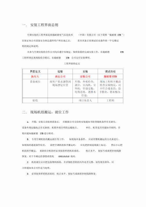
一. 安装工程界面总则空调安装的工程界面是指施耐德电气信息技术(中国)有限公司(以下简称“施耐德ITB ”)在保证本公司设备安全到达最终用户所在地之后,直至具备正常调试启动条件的一个完整过程的规定和说明。
凡参与空调安装的合作公司均应遵守本规定,保质保量的完成安装工作,在施耐德ITB 工程师到达现场验收合格后,由施耐德ITB 公司支付安装费用。
工程界面的定义二. 现场机组搬运,就位工作A. 开箱:安装人员接到设备后,应根据公司交给的安装通知书检查随机备件有无缺失,设备外观运输标志有无缺损,机箱外部注明的运输地点、单位、机型是否同通知书相同,否则应通知施耐德ITB进行核对。
B. 专用空调机组的搬运就位等工序,如现场具备条件,应采用整机搬运的方式来进行。
如现场的通道条件较差,需把空调机组拆开搬运时,应先把控制连线做上标记,然后小心把机组拆开搬运,重新组合机组时必须按原样把机组重组,校正水平,按标号重新把控制线路恢复,对于不确定的事情请致电4008101315 询问。
C. 机组就位后应把包装物料拆除,并详细检查机组内外是否完整,如发现有损坏,应立即通知本公司作适当处理。
D. 必须按原样把机组重组,校正水平,按标号重新把控制线路恢复。
三. 现场搬运机组时的保护A. 当搬运机组时,必须采用柔软物料对机组提供适当的保护,以免机组搬运时因碰撞而受损坏。
B. 搬运中遇到楼房门道过低,需把空调机组放倒时,可以将机组轻微侧卧进行搬运,可以不拆压缩机。
四. 场地基本要求A. 避免把机组安装在受阳光直接照射的地方。
B. 机组的正面,两侧应保留1m距离的维修空间,如空间状况较充分,后面最好留1m的距离,最小不少于300mm.C. 下送风,上回风的机组,要求用以送风的高架地板的净高度( 地板下龙骨和走线槽外无挡风的情况下) 必须不少于300毫米,机组顶部与天花板之间的高度要求不少于500毫米。
以达到最佳的气流循环效果。
D. 上送风,前回风的机组,在机组前面 1 m以内不得有大面积阻挡物,送风口必须安装送风风帽或送风管道。
施耐德ATV212变频器安装手册
แఱۉڤഘሞዐࡔ
1987Ljแఱۉڤഘሞཀৄׯ૬ڼᅃॆࢇጨ߾નනનLjॽୟഗरຍڟټዐࡔLjൽدپཥԍ၃ ີLj๑ڥዐࡔᆩࢽᆩۉҾඇႠྺٷሺഽLjժྺୟഗՔጚॺڦ૬ፕକጝሁࠋڦ၅ă90؛پLjแఱ ۉڤഘഌူಈആ୲ံॽਸ࠲௬ӱټዐࡔLjຐକዐࡔ๑ᆩุڨਸ࠲پ้ڦă
SCDOC1563
5
安全信息
安全信息
§
重维护设备之前,请仔细阅读下述说明并通过查看来熟悉设备。 下述特别信息可能会在本 文其他地方或设备上出现,提示用户潜在的危险,或者提醒注意有关阐明或简化某一过程的信息。
“危险”或 “警告”标签上的这种标志表示存在电击危险,如果使用者不遵照使用说明进行操作会 造成人身伤害。
转换 ATV21 --> ATV212. . . . . . . . . . . . . . . . . . . . . . . . . . . . . . . . . . . . . . . . . . . . . .61 概述. . . . . . . . . . . . . . . . . . . . . . . . . . . . . . . . . . . . . . . . . . . . . . . . . . . . . . . . . . . . . .62 不同之处 . . . . . . . . . . . . . . . . . . . . . . . . . . . . . . . . . . . . . . . . . . . . . . . . . . . . . . . . . .62 端子和开关布局比较 . . . . . . . . . . . . . . . . . . . . . . . . . . . . . . . . . . . . . . . . . . . . . . . . .63
施耐德电气 DTS 8000ES 系列外挂式机柜空调操作及使用说明书

外挂式机柜空调操作及使用说明书1 手册提示 (5)2 搬运 (5)2.1 运输 (5)2.2 储运 (5)2.3 开箱 (5)3 供货范围 (6)4 一般信息 (6)5 铭牌 (6)6 安全 (7)7 功能 (7)7.1 配置与功能 (7)7.2 工作原理 (7)7.3 冷凝物 (8)8 技术规格书 (8)8.1电气原理图 (8)8.2备品备件 (9)8.3安装开孔 (9)8.4气流原理 (12)8.5技术参数 (12)9 安装 (16)9.1 概述 (16)9.2 安装工作 (16)9.3 电气连接 (17)10 运行条件 (17)11 投入使用和功能 (17)11.1 概述 (18)11.2 操作显示器 (18)11.3启动测试模式 (18)11.4 门触点 (18)11.5 设备故障 (19)12 参数查看与设置 (19)13 清洁和维护 (20)13.1 清洁 (20)13.2 维护 (20)14 停止使用 (21)15 故障排除 (21)16 保障条款 (21)附表I (22)1 Hints on the manual (23)2 Handling (23)2.1 Transport (23)2.2 Storage (23)2.3 Unpacking (24)3 Scope of delivery and options (24)4 General Information (24)5 Name plate (24)6 Safety (25)7 Function (25)7.1 Function and configuration (25)7.2 Operating principles (26)7.3 Condensate (26)8 Technical data (27)8.1 Circuit Diagram (27)8.2 Spare parts (28)8.3 Installation Cut-out (28)8.4 Airflow principle (31)8.5 Technical Data (31)9 Installations (35)9.1 General (35)9.3 Electrical connection (36)10 Operating condition (37)11 Putting into operation and function (37)11.1 General remarks (37)11.2 Operation display (37)11.3 Start-up / Test mode (38)11.4 Door contact (38)11.5 Equipment fault (38)12 Parameters View and Settings (39)13 Cleaning and Maintenance (40)13.1 Cleaning (40)13.2 Maintenance (40)14 When not in used (40)15 Trouble shooting (41)16 Warranty Conditions (41)Appendix I (42)1 手册提示此手册为百能堡电气科技有限公司(以下简称百能堡)提供的门装或侧装螺栓固定,外挂式机柜空调系列的安装运行指南。
施耐德精密空调安装线缆开关配置要求
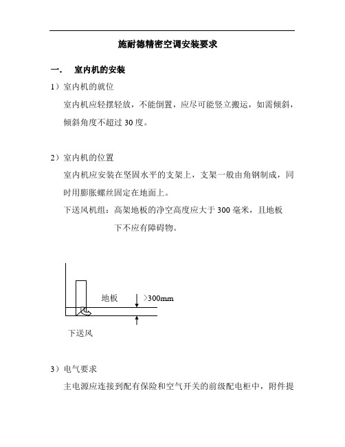
施耐德精密空调安装要求一.室内机的安装1)室内机的就位室内机应轻摆轻放,不能倒置,应尽可能竖立搬运,如需倾斜,倾斜角度不超过30度。
2)室内机的位置室内机应安装在坚固水平的支架上,支架一般由角钢制成,同时用膨胀螺丝固定在地面上。
下送风机组:高架地板的净空高度应大于300毫米,且地板下不应有障碍物。
下送风3)电气要求主电源应连接到配有保险和空气开关的前级配电柜中,附件提供各种机型的配电参数。
常规情况为三相五线制。
电源线放到机器左前角,再留2米即可。
4)供水要求由于空调具有加湿和除湿功能,应具备供水管和排水管各一根。
供水管:采用6分的镀锌钢管或PPR水管,在靠近机组的地方应安装截止阀。
排水管:采用1寸的镀锌钢管或PPR水管。
并需要有1%的坡度以供排水。
供水管和排水管的末端接头,应放置在靠近机组左前方的位置约500毫米以内,便于今后的维护。
主机供水管排水管二.室外机的安装室外机应安装在平坦结实的混凝土地面上。
垂直气流的室外机应制作专门的垂直支架,且要固定在坚固的混凝土地面上。
>4M三.精密空调安装进排水及管道井开口尺寸等要求1进水管要求6分管,每台空调左后方附近留有单独阀门控制且带有6分外丝。
2排水管要求排水总管φ90,5台或4台排水管分别φ50每台空调左后方附近留有φ40排水管且带阀门,单台排水管用1寸管。
3空调周围有5cm高5cm宽的凸沿围挡,围挡圈内有地漏。
4冷媒管由于管距较长(超过30米),需使用大于标配尺寸,现采用φ25和φ19铜管。
5管道井开口尺寸五楼空调到楼顶为:最小300×500mm六楼空调到楼顶为:最小100×250mm四.配电要求:1、5楼9台TDA V2202 80KW双系统精密空调每台精密空调需1只输入开关,≥100A)(1) 进线电缆-截面:WDZC-YJY4X 25+1无卤低烟阻燃电力电缆-芯数:三相五线-距离:从低压配电到空调-材料:多股铜电缆-数量:1组(2) 给水、排水管:进水6分管,排水1寸管2、6楼2台TDA V1822 60KW双系统精密空调每台需1只输入开关≥80A)(1) 进线电缆-截面:WDZC-YJY4X 25+1无卤低烟阻燃电力电缆-芯数:三相五线-距离:从低压配电到空调-材料:多股铜电缆-数量:1组(2) 给水、排水管:进水6分管,排水1寸管(3):重量及尺寸:。
施耐德电气 U10 绝缘导体系统安装说明书
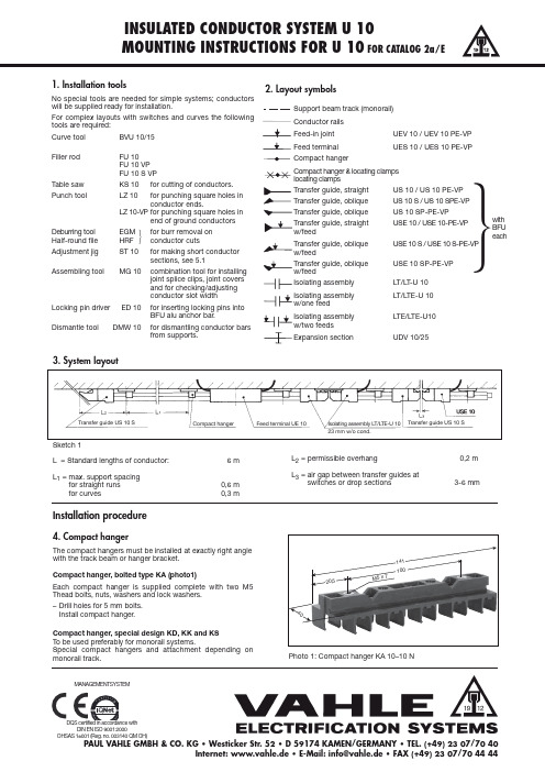
INSULATED CONDUCTOR SYSTEM U 10MOUNTING INSTRUCTIONS FOR U 10FOR CATALOG 2a/E1. Installation toolsNo special tools are needed for simple systems; conductors will be supplied ready for installation.For complex layouts with switches and curves the following tools are required:Curve tool BVU 10/15Filler rodFU 10FU 10 VP FU 10 S VP Table saw KS 10for cutting of conductors.Punch toolLZ 10for punching square holes in conductor ends.LZ 10-VP for punching square holes inend of ground conductorsDeburring tool EGM for burr removal on Half-round file HRFconductor cutsAdjustment jig ST 10for making short conductor sections, see 5.1Assembling toolMG 10combination tool for installing joint splice clips, joint covers and for checking/adjusting conductor slot width Locking pin driver ED 10for inserting locking pins intoBFU alu anchor bar.Dismantle toolDMW 10from supports.2. Layout symbolsSupport beam track (monorail)Conductor rails UEV 10 / UEV 10 PE-VPUES 10 / UES 10 PE-VPCompact hangerCompact hanger & locating clamps locating clampsUS 10 / US 10 PE-VP US 10 S / US 10 SPE-VP US 10 SP-PE-VP USE 10 / USE 10-PE-VP USE 10 S / USE 10 S-PE-VP USE 10 SP-PE-VP Isolating assembly LT/LT -U 10LT/LTE-U 10LTE/LTE-U10Expansion sectionUDV 10/25L = Standard lengths of conductor: 6 m L 1= max. support spacingfor straight runs 0,6 m for curves0,3 mL 2= permissible overhang0,2 m L 3= air gap between transfer guides atswitches or drop sections3-6 mmInstallation procedure4. Compact hangerThe compact hangers must be installed at exactly right angle with the track beam or hanger pact hanger, bolted type KA (photo1)Each compact hanger is supplied complete with two M5 Thead bolts, nuts, washers and lock washers.–Drill holes for 5 mm bolts.Install compact hanger.Compact hanger, special design KD, KK and KS To be used preferably for monorail systems.Special compact hangers and attachment depending on monorail track.Photo 1: Compact hanger KA 10–10 Nwith BFU eachဲ3. System layoutဲMANAGEMENTSYSTEM20,5100M 5 x 7Sketch 1MOUNTING INSTRUCTIONS FOR U 105. ConductorsConductor sections are connected with feed-in joint splices (photo 2). It is important for good electrical contact that the conductor ends are clean and free of residue and that any burrs are removed. The feed-in joint splices compensate the expansion and contraction of the conductors (see instructions 6 and photo 2). The joint splice is protected by an insulating cover.Standard conductor sections are supplied ready for the installation of the joint splice. If a section has to be cut during installation, the end has to be prepared as shown under instructions 5.1.Installation sequence, when conductor is installed starting on the left and progressing towards the right, is as follows:–Start installation at an anchor point (switch or end of system).–Install standard length conductor sections. –For system with curves refer to instr. 11.–Make and install short conductor sections (see instr. 5.1).Maintain correct air gap between each conductor section (see instr. 6).–Push joint splice cover onto the left end of the conductor bar.P ush in splice cover far enough so that the conductor becomes accessible (see photo 3).–Snap-in metal splice clip at the right end of the conductor (see photo 4).–Install conductor section into compact hanger and push left end of conductor into the splice clip of the already installed conductor section.–Use installation tool MG 10 to push joint splice cover over joint splice, tap lightly if required (see photo 5).–Maintain correct air gap between each conductor section (see instr. 6 and photo 2).–Impress joints with installation tool MG-ST 10. Press plastic part to the bottom of the conductor. (photo 5).5.1 Preparing conductor end for joint spliceP repare short sections in an efficient way. For preparation proceed as follows (fig 3):–Measure exact length required.–Use adjustment jig ST 10 and pull conductor approx. 80 - 100 mm out of insulating shroud.–Use hollow end of ST 10 and push back conductor to stop (70 mm, see photo 6).Photo 2: Installed joint splice UEV 10, without coverPhoto 3: Joint splice coverPhoto 4: Feed-in joint splice UV 10Photo 5: Installation toolMG 10Photo 6: Adjustment jig ST 10a = 0-4 m mMOUNTING INSTRUCTIONS FOR U 10Photo 7: Punch tool LZ 10 PE-VPPhoto 8: Remove outside burr and bevel with half-round filePhoto 9: Remove inside burr with round file800 (+ 30 m m )e x p a n s io n s e c t ionPhoto 10: Expansion section–Cut conductor to exact length required; use hacksaw or table saw KS (fine teeth blades only).–Use punch tool LZ 10 PE-VP to punch square holes into each end of conductor (see photo 7 and fig. 2).Attention: avoid two punched holes (prolongation of opening)–Remove burr from cutǞoutside the conductor profile with half-round file HRF (photo 8)Ǟinside the conductor profile with half-file RF (photo 9)–Use hollow end of ST 10, short setting, and push plastic shroud into center of conductor, (photo 6).6. Conductor expansion and contractionThe special design of the feed-in joint splice UEV 10 compensates for expansion and contraction of the conductors due temperature difference.The conductors have to be anchored with locating clamps USK 10to assure controlled expansion and contraction and to avoid a push-along effect by dragging collectors. A fixpoint should be provided every 36 m for long, straight systems (see instr. 10).Expansion section UDV 10/25 C-P E-VP (see photo 10) with expansion capability of max. 30 mm should be installed on systems with expansion joints in the track beam and/or in the building. Use locating clamps on each side of expansion section (see instr. 10, ).Dependent on the expected temperature difference an air gap “a”has to be set during installation (photo 2). Set air gap “a” according to the graph below for sections of max. 6 m.Max. expected temperature = 40 °C.Min. expected temperature = 0 C.Example (graph below):Installation temperature 20 °C Air gap …a“ = 2 mm (joint)15 mm (expansion joint)According to the expected temperature difference of the above example, conductor bars installed at 20° C ambient temperature should have an air gap of 2 mm; expansion joints 15 mm.If the temperature is higher than 40° C or lower than 0 °C consi-der more joint sand conductor sections that are shorter than 6 m.In case of expansion joints in buildings use more joints or expan-sion sections.(40 f ür VP)(40 f ür VP)(80 f ür VP)Fitting length-10+10+20+30+40+50Measure …a“ in mm1234102030I n s t a l l a t i o n t e m p e r a t u r e ° 15fig. 2:fig. 3:MOUNTING INSTRUCTIONS FOR U 10a = 0-4 m m Photo 11: Feed terminal UEV 10 without cover25w /o c o nd .7,5Sketch 5: oblique rail cut with BFU 1013: Transfer guide, compact arrangement, 6poles7. Feed terminalsInstall feed terminals close to the mains (refer to photo 11 and instr. 5).–If required, preparation of conductor bar as shown under instructions 5.1.–Max. two cables can be connected using a spade connector dim. 6.3 x 0.8 mm.–Provide tension relief for feed-in cables.–Impress feed terminal as per instr. 5Make certain that connecting cables do not restrict movement of conductors or collectors and impede longitudinal expansion of conductors during temperature fluctuation.8. Transfer guide (photo 12)and transfer guide with feed-pointTransfer guides are used with switches, drop sections, turntables and air gaps; they are also used as end caps.Installation procedure:1)Chamfer conductor at punched side properly to allow easy push-over of the detent of the transfer guide.2)Push transfer guides onto anchor bar BFU (photo 13).3)P ush conductor rails into transfer guides. Detents must fit properly.4)Bolt anchor bars BFU to the appropriate attachment surface.5)Impress transfer guides in the same way than joints (instr. 5,photo 5)8.1 Placement of transfer guideStraight transfer guides are used with straight track beam cuts.Oblique transfer guides are used on one side of an oblique cut track beam (see fig. 4, 5 and 6).8.2 Conductor bar preparationTo install joint caps on top of each other, the PE-VP rail has to be cutted at one materail group (e.g. switch or lifter).8.2.1 Preparation of conductor bar for phase and earth asshown under instructions 5.1.8.2.2 For PE-VP (only for transfer guides)- Cut section to length, if necessary.-Pull conductor profile 90 – 100 mm out of the isolating profile with adjustment jig ST 10.-Push back conductor profile by 80 mm.US 10 S / US 10 S -PE-VP (USE 10 S / USE 10 S-PE-VP)US 10 / US 10 SP-PE-VP (USE 10 / USE 10 SP-PE-VP)US 10 S / US 10 S -PE-VP (USE 10 S / USE 10 S-PE-VP)US 10 / US 10 SP-PE-VP (USE 10 / USE 10 SP-PE-VP)L.H.switchhori z ontal arrangementR.H.switchhori z ontal arrangementSketch 4MOUNTING INSTRUCTIONS FOR U 10- Cut conductor to exact length required; use hacksaw or table saw KS (fine teeth blades only).-Use punch tool LZ 10 to punch square holes into each end of conductor (see photo 7 and fig. 2)-Attention:avoid two punched holes (prolongation of opening).-Remove burr from cut.Ǟoutside the conductor profile with half-round file HRF (photo 8).Ǟinside the conductor profile with half-file RF (photo 9).-Use hollow end of ST 10, short setting, and push plastic shroud into center of conductor (photo 6).8.2.3 For phase, PE and PE-VP-for transfer guides with end feed:fix feed-in clamp to conductor profile (photo 14), leave the square hole open (fig. 2 and 7).-P ush transfer guides on front side of the conductor profile until they snap into place (photo 12).-for USE 10: flat terminal plug 6,3 x 0,8 mm8.3 Installation of anchor bars–Mark drilling holes for BFU on attachment surface (see fig.5 and 6). Caution : Make sure transfer guides have sufficient clearance when switch moves.–Drill through-holes M 5 into attachment surface.–Push transfer guides onto anchor bar BFU.–Bolt anchor bar BFU to attachment surface.–Insert locking pins to fix position of transfer guides. (Use pin driver ED 10).–Make sure that the head of a fixing screw does not coincide with the track beam cut when having an oblique cut for switches.Facing transfer guides must be accurately aligned with each other to ensure smooth collector passage.Permissible max. gap between transfer guides is 6 mm, max. off-set in both directions is ± 3 mm.Track beams of switches and drop sections must be properly aligned before starting the installation of conductor rails.9 Isolating assembly9.1 For phase and earth (photo 15)-prepare conductor bar as shown under 5.1in addition: chamfer conductor at punched side properly to al-low easy push-over of the detent of the isolating assembly.(40 f ür VP)(40 f ür VP)(80 f ür VP)804040Fitting lengthfig. 7:fig. 8:1337,523w /o c o nd.Photo 14: Feed clip SE 10 installedMOUNTING INSTRUCTIONS FOR U 10The following combinations are possible:= LT/LT- U 10 without feed terminals= LT/LTE-U 10 with feed terminal on one side= LTE/LTE-U 10 with feed terminal on both sidesAfter the two pieces have been pushed each onto a conductorthey must be pressed together to interlock.For impressing the isolating assembly refer to instr. 5.If system hangers do not permit the isolating assembly to sup-port against the track beam (distance contact surface to trackbeam more then 10 mm), additional compact hangers must beinstalled at approx. 100 mm distance left and right of the isolatingassembly for stabili z ation.9.2 For PE and VPIsolating assemblies are formed by two transfer guides. Prepara-tion of conductors as under instr. 8.The following combinations are possible:= 2x US 10 PE-VPU 10 without feeding= 1x US 10 PE-VP, 1x USE 10 PE-VPU 10 with feeding at one side= 2x USE 10 PE-VPU 10 with feeding at both sidesImpress transfer guides as under instr. 510. Anchor points (Photo 16)T o prevent the conductor sections from sliding anchor points must be provided (see fig. 9).Anchor PointsNo.Position Consisting ofᕃSwitches and Transfer guide anddrop sections BFU (see instructions 8.3)ᕄContinuouse long runs USK 10 / USK 10 A locatingclamps left and right of bolted-on ᕅExpansion sections compact hangerat building or trackexpansion jointsThe distance between two anchor points should not exceed 36 m (120‘).Sequence of work:(Locating clamps)–Bolt on compact hangers.–Mark the position of the locating clamp before pushing the conductor into the bolted compact hanger.–Bolt locating clamps on the conductors staggered left and right to the compact hanger. (image 16).–Push the conductors into the hanger.Phase and PE–Install conductor bars, mark position of locating clamps befo-re pushing conductor sections into compact hanger.–Install locating clamps as marked on conductor sections and tighten securely; stagger locating clamps as shown in photo 16.–Push conductor bars into compact hanger.PE-VP–Provide two borings diam. 3,2 at the back side of the conduc-tor with the drilling template BS 10 A. Distance of borings as per instr. 10.–Push a safety clamp USK 10 A in each boring and engage conductor in fixed compact hanger.Photo16: Compact hanger with staggered locating clamps USK 10 Fig. 9→→→→→→MOUNTING INSTRUCTIONS FOR U 1011. Bending of conductorsHori z ontal or vertical curves can be supplied ready for installati-on. For curves to be made at the job site curve tool BVU 10 VP (photo 17) and filler rod FU 10 is required.Bending procedure:–Draw radius of curve on a floor or flat surface (fig. 11)–Determine required length of curve (stretched length) and mark it on conductor section.–Cut conductor section approx. 500 mm longer as required.–Insert filler rod into conductor section.–Turn handle on curve tool to lift upper roller. Insert conductor section with filler rod into the correct groove of lower rollers.–Sligthly increase pressure with upper rollers and push conductor back andforth.–To avoid kinks, start each back-and forth movement of the conductor an inchcloser to the center of the curve. –Repeat this procedure until the radius is obtained.–Remove filler rod.–Cut the conductor to the required length.–On curves with smaller radii than 0,7 m a straight section of approx. 0,1 m on each end is required to assure a good splice (fig. 8).–P ass through the curves with test collector and check conductor slot width (5 - 5,5 mm)Attention:Use the slotted conductor type U10/25 C PE-VP-G only for hori-z ontal inner curves. Alternativly cut the non-slotted conductor at the back every 30 mm considering a depth of 11 mm and a slot width of 1 – 2 mm.12. CollectorsUse collectors preferebly only for one travel direction (photo 18). Use the collector type KDS 2/40 for travel in both directions. Compact collectors that swivel in and out must be adjusted vertically at right angle to the conductors. Example: carriers in monorail systems for maintenance reasons.Make certain that connecting cables are high flexible and do not restrict movement of the collectors. Avoid formation of cable loops.12.1 Collector bracketsCollector brackets must be installed exactly parallel and right angle to the conductor bars. Installation height from bracket to contact surface of the conductor is shown in the following table:Holes for single collector installation must be on 14 mm centers if standard compact hangers are used.13. Installation inspectionAfter installation has been completed inspect all components for correct fit, distance, line-up etc. Make trial runs and pay special attention to collector tracking.Collector Bolt holesWorking height type of collector mmKST 2/40phase M 580ground M 6KUFU 25-2 thru 1088KDS 2/40-1 thru 12-142 x slotted holes987 x 15Photo 17: Curve tool BVU 10 VPDi r en z i o n ed i m a r c i a 2 x slotted holes7 x 15F üllstabIdentnr.: 143279=....RMOUNTING INSTRUCTIONS FOR U 1014. CommissioningSafety instructionsThe conductor system U 10 and its components are designed in accordance with VDE 0100 and are touchproof according to VDE 0470, part 1. After installation the touch-proofness must not be restricted, e.g. make sure a maximum conductor slot opening of 5,5 mm.After installation has been completed make test runs considering the following aspects:First test run with low speed.Collectors must run in conductors without vibration.All transfer applications require special attention for proper pas-sing over and re-tracking of collectors. If necessary open out the slot of the shrouding with the conductor joint assembly tool MG-SW 10.Avoid sparking at collector carbons (sparking is caused by dirty and oxidised conductor surfaces.Take care of proper passing over of collectors especially at trans-fer guides.15. Maintenance instructionsUnder normal working conditions the conductor system does require little maintenance.We recommend to carry out the following maintenance work in regular intervalls:1.Inspection of conductors:Visual inspection in 4 weeks intervals. Control conductor expansion and look for burned spots.Remove carbon dust deposits especially in transfer guide and isolating assembly areas.Procedure:a)Manual cleaning with comercial vacuum cleaner.b)Additional adjustment of a cleaning collector (same designthan collector).c)Use of additional automated vacuum cleaner in regularmaintenance intervals.Adhere to the maximum vertical and hori z ontal offset of 3 mm at transfer sections for switches, lifting devices etc. The max.airgap between the two alternate transfer guides is 6 mm.2.Inspection of collectorsa)Mechanical control:Flexibility of links, bearings and support stems; check for mechanical wear and damages.b)Electrical control:Check the abrasion of brushes, the tightness of contact screws and cable fixings.c)Contact pressure:Use spring-scale to pull the collectors out of the conductor bar. The contact pressure must be approx. 3,5 N per brush.MOUNTING INSTRUCTIONS FOR U 10Half-round file HRF for deburring the outer side of short lenght of conductor profileRFHRFTable sawto cut isolating- and conductor profiles with length supplement.Connection: 220 V , 50 H z .Conductor punch toolT o stamp the joint notch into the conductor profile at short lengt-hs. Combitool U10 and U10-VPDeburring toolRound file RF for deburring the inner side of short length of conductor profileCurve toolto bend the conductor U10 and U10 PE-VP vertical and hori z ontal.The filling rod has to be ordered seperatly.MOUNTING INSTRUCTIONS FOR U 10Adjustment jigto adjust short length of condctor and isolating profileConductor joint assembling tool1. to impress the conductor profile into the joint2. to open out the conductor slot3. to close the joint coverLocking pin driverfor BFU aluminium anchor bars for transfer guidesConductor dismantle toolto desmantle the conductors out of the compact hangerBoring template for fixpoints Twist drillfor preparation of borings for saftey clampsUSK 10 A at fixpointsNOTES11Mounting instructions for catalog No. 2a/E 20100810 • P r i n t e d i n G e r m a n y • 1026362 • 08/2010PAUL VAHLE GMBH & CO. KG • D 59172 KAMEN/GERMANY • TEL. (+49) 23 07/70 40Internet:www.vahle.de•E-Mail:*************•FAX(+49)2307/704444certified by DQS according toDIN EN ISO 9001:2000OHSAS 18001 (Reg.-Nr . 003140 QM OH)。
施耐德ATV61变频器安装手册(中文)
伤害危险
连接电抗器支撑与托台的螺钉很难取下,存在受伤危险。须采取所有可能的预防 措施来防止危险,并使用保护手套。 不按照使用说明会导致严重伤害。
3 取下连接变频器与托台的螺钉并使用起重机搬运变频器。变频器为此配备了吊耳 ( 图 4)。
警告
翻转危险
由于变频器可能翻转,因此在没有支撑的情况下决不要将变频器竖直放置(图5)。 不按照使用说明会导致死亡或严重伤害以及设备损坏。
警告
不正确的变频器操作
• 如果变频器长时间没有通电,则其电解电容器的性能将会下降。 • 如果变频器将在很长一段时间内不使用,应每两年将变频器至少通电 5 小时,以恢复
电容器的性能,然后检查其工作情况。建议不要将变频器与线电压直接连接,应使用 可调的 AC 电压源逐渐加压。 不按照使用说明会导致设备损坏。
图4
图5
4
初步建议
安装变频器
- 在安装直流电抗器之前,应按照本手册中描述的建议将变频器安装在墙上或安装在机柜的背部。
安装直流电抗器
ATV61H D55M3XD 至 D90M3XD 与 ATV61H D90N4D 至 C63N4D 变频器在供货时不带直流电抗器。 ATV61H D55M3X 至 D90M3X 与 ATV61H D90N4 至 C63N4 变频器在供货时带有一个直流电抗器,此电抗器必须安装在变频器的顶部并按 照本文档中描述的建议连线。变频器与 3 相电路电源连接时,必须使用此电抗器。
- 将直流电抗器安装在机柜的背部或安装在变频器顶部的墙上,并进行连线。在第 12 页上给出了电抗器的安装与连线指导。 - 检查并确认变频器与电抗器底盘间的密封能够满足使用要求。
建议
阅读并了解 “编程手册”中的使用说明。
施耐德精密空调安装工程界面及技术要求规范v3
一. 安装工程界面总则空调安装的工程界面是指施耐德电气信息技术(中国)有限公司(以下简称“施耐德ITB”)在保证本公司设备安全到达最终用户所在地之后,直至具备正常调试启动条件的一个完整过程的规定和说明。
凡参与空调安装的合作公司均应遵守本规定,保质保量的完成安装工作,在施耐德ITB 工程师到达现场验收合格后,由施耐德ITB 公司支付安装费用。
工程界面的定义二. 现场机组搬运,就位工作A. 开箱:安装人员接到设备后,应根据公司交给的安装通知书检查随机备件有无缺失,设备外观运输标志有无缺损,机箱外部注明的运输地点、单位、机型是否同通知书相同,否则应通知施耐德ITB进行核对。
B. 专用空调机组的搬运就位等工序,如现场具备条件,应采用整机搬运的方式来进行。
如现场的通道条件较差,需把空调机组拆开搬运时,应先把控制连线做上标记,然后小心把机组拆开搬运,重新组合机组时必须按原样把机组重组,校正水平,按标号重新把控制线路恢复,对于不确定的事情请致电4008101315询问。
C. 机组就位后应把包装物料拆除,并详细检查机组内外是否完整,如发现有损坏,应立即通知本公司作适当处理。
D. 必须按原样把机组重组,校正水平,按标号重新把控制线路恢复。
三. 现场搬运机组时的保护A. 当搬运机组时,必须采用柔软物料对机组提供适当的保护,以免机组搬运时因碰撞而受损坏。
B. 搬运中遇到楼房门道过低,需把空调机组放倒时,可以将机组轻微侧卧进行搬运,可以不拆压缩机。
四. 场地基本要求A. 避免把机组安装在受阳光直接照射的地方。
B. 机组的正面,两侧应保留1m距离的维修空间,如空间状况较充分,后面最好留1m的距离,最小不少于300mm.C. 下送风,上回风的机组,要求用以送风的高架地板的净高度(地板下龙骨和走线槽外无挡风的情况下)必须不少于300毫米,机组顶部与天花板之间的高度要求不少于500毫米。
以达到最佳的气流循环效果。
D. 上送风,前回风的机组,在机组前面1m以内不得有大面积阻挡物,送风口必须安装送风风帽或送风管道。
施耐德 24DDC5010 温控器 说明书
本说明书对温控器设置、配线及各部分名称等进行说明,使用本产品前,请认真阅读本说明书,在理解内容的基础上正确使用。
并请妥善保存,以便需要时参考。
1)本产品不得使用在原子能设备以及与人命相关的医疗器械等方面。
2)本产品使用在家庭环境内有时会发生电波干扰。
此时应采取充分对策。
3)本产品通过强化绝缘进行触电防护。
将本产品嵌入设备上以及配线时,需遵守嵌入设备所符合的规格要求。
4)本产品使用时所有室内配线超过30m 的场合以及配线在室外的场合为了防止浪涌发生,需设置适当的浪涌抑制电路。
5)本产品是以安装在盘面上使用为前提而生产的,为了避免用户接近电源端子等高压部分,请在最终产品上采取必要措施。
6)请务必遵守本说明书中的注意事项,否则有导致重大伤害或事故的危险。
7)配线时请遵守各地的规定。
8)为了防止机器损坏和防止机器故障,请在与本产品连接的电源线或较大容量的输入输出线上安装适当容量保险丝等方法保护电路。
9)请不要将金属片及导线碎屑混入本产品中,否则可能导致触电、火灾、故障。
10)请按规定力矩确实的拧紧螺丝。
如果螺丝不完全拧紧,有可能导致触电、火灾。
11)为了不妨碍本产品散热,请不要堵塞机壳周围散热窗孔及设备通风口。
12)本产品未使用的端子不要接任何线。
13)请务必在断电后再进行清洁,请用干的软布擦产品上的污垢,而且不用吸湿剂类,否则可能导致变形、变色。
14)请不要用硬物敲打或擦蹭显示面板。
15)本说明书以读者具有电气、控制、计算机以及通信等方面的基础知识为前提。
16)本说明书中使用的图例、数据例和画面例,是为了便于理解说明书而记入的,并不保证是其动作的结果。
17) 为了长期安全的使用本产品,定期维修是必要的。
本产品的某些部件有的受寿命限制,有的因长年使用性能会发生变化。
18)在没有事先预告情况下,有可能变更说明书的内容。
有关说明书的内容期望无任何漏洞,您如果有疑问或异议,请与本公司联系。
1)当本产品的故障或异常有可能导致系统重大事故的场合,请在外部设置适当的保护电路。
施耐德机架式配电单元安装手册AP6201CH, AP6221CH 说明书
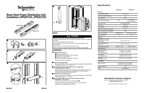
990-961908/2014Basic Rack Power Distribution Unit Installation (AP6201CH, AP6221CH)SafetyInstallationMounting Kit ContentsMounting brackets (2)Flat head Phillips screws, 6-32 x 5/16 (4) Toolless mounting pegs (2)Flat head Phillips screws, 8-32 x 5/16 (2)Power cords are not provided.Install mounting bracketsUse four (4) 6-32 x 5/16 screws to install the brackets to the Rack PDU.Torque the screws to 0.7 ~ 1.0 N*mHorizontally mount the Rack PDU on the vertical rails of a standard EIA-310 cabinetSecure the brackets to the back of the rear vertical rails using two (2) screws and two (2) cage nuts, not provided. 1U of rack space is required to accommodate the Rack PDU. Install toolless mounting pegsUse the two (2) 8-32 x 5/16 screws to install the pegs to the Rack PDU.Torque screws to 0.7 ~ 1.0 N*mMount the Rack PDU in a vertical 0U accessory channel of a NetShelter ™ SX cabinetInstall the Rack PDU as shown in illustration .In one vertical 0U accessory channel, you can mount six (6) AP6201CH or AP6221CH Rack PDUs.SpecificationsWorldwide Customer SupportCustomer support and warranty information is available at .© 2014 Schneider Electric. All rights reserved.DANGERHAZARD OF ELECTRIC SHOCK, EXPLOSION, OR ARC FLASH• To avoid possible electrical shock and equipment damage, use only the supplied hardware.• This product is suitable for indoor use only.• Do not install this product in environments with excessive humidity or high temperatures.• Plug the product into a properly grounded power outlet.Failure to follow these instructions will result in death or serious injury.AP6201CHAP6221CHElectricalNominal input voltage 200 - 240 VACRated Input Current (Phase)16A Input frequency 50 HzSurge Protection Rating N/AL-N/L-G/N-G 3KA In/10KA ImaxInput connection IEC 320 C20 (16A)Input power3.52 KVA Output voltage200-240 VACMaximum output current (Outlet)10A Maximum output current (Phase)16AOutput connections GB1002 (10A)IEC 320 C13 (10A)Outlet quantities 812PhysicalDimensions (H x W x D)(depth does not include toolless pegs)44.5 x 4.35 x 3.8 cm Shipping dimensions (H x W x D)49.5 x 6.0 x 5.0 cmWeight/shipping weight 0.95 kg / 1.0 kg1.16 kg / 1.21 kgEnvironmental Maximum elevation (above MSL)Operating/Storage 0–3048 m (0–10,000 ft) / 0–15240 m (0–50,000 ft)TemperatureOperating/Storage –5 to 45°C (23 to 113°F) / –25 to 65°C (–13 to 149°F)HumidityOperating/Storage 5–95% RH, non-condensingCompliance EMC verification EN 55022,Class A, EN 55024, EN 61000-3-2, EN 61000-3-3Safety verification CE ROHS2011/65/RoHS990-961908/2014机架式配电单元安装手册(AP6201CH, AP6221CH)安全安装安装包内容安装支架(2)平头螺丝,6-32×5/16(4) 免工具安装固定销(2)平头螺丝,8-32×5/16(2)您将需要购买电源线。
施耐德空调操作说明
施耐德空调操作说明操作说明:施耐德空调1、产品概述1.1 产品名称:施耐德空调1.2 产品型号:[填写具体型号]1.3 主要特点:[填写产品的主要特点]1.4 适用场景:[填写产品适用的场景]2、安装及调试2.1 安装准备2.1.1 安装位置选择:[填写安装位置选择的注意事项] 2.1.2 安装工具及材料准备:[需要准备的工具和材料] 2.2 安装步骤2.2.1 安装室内机:[填写室内机安装步骤]2.2.2 安装室外机:[填写室外机安装步骤]2.2.3 连接管道和电源:[填写连接管道和电源的步骤] 2.3 调试步骤2.3.1 开通电源:[填写开通电源的步骤]2.3.2 设置温度和模式:[填写设置温度和模式的步骤]2.3.3 检查制冷效果:[填写检查制冷效果的步骤]3、使用方法3.1 开关机控制3.1.1 开机:[填写开机的步骤]3.1.2 关机:[填写关机的步骤]3.2 温度控制3.2.1 温度调节:[填写温度调节的步骤]3.2.2 温度显示:[填写温度显示的方式]3.3 模式选择3.3.1 制冷模式:[填写选择制冷模式的步骤及相关说明] 3.3.2 制热模式:[填写选择制热模式的步骤及相关说明] 3.3.3 除湿模式:[填写选择除湿模式的步骤及相关说明] 3.3.4 送风模式:[填写选择送风模式的步骤及相关说明] 3.3.5 自动模式:[填写选择自动模式的步骤及相关说明] 3.4 风速控制3.4.1 高速:[填写选择高速风的步骤及相关说明]3.4.2 中速:[填写选择中速风的步骤及相关说明]3.4.3 低速:[填写选择低速风的步骤及相关说明]3.4.4 自动风速:[填写选择自动风速的步骤及相关说明]附件:1、安装图纸:[列出安装图纸的名称及相关信息]2、使用说明书:[列出使用说明书的名称及相关信息]法律名词及注释:1、民事法律行为:指个人或组织在民事关系中,具有法律约束力的行为。
2、契约:指以协商一致的方式订立、修改、解除的具有法律约束力的合同。
施耐德空调使用说明
项
5. 冷水三通阀不能关闭
关闭阀门,手动控制旋钮,更换伺服器
湿度控制
1.控制面板上的参数设置不正确 查看控制器手册
2.潜在负荷高于预期
检查潜在负荷, 新鲜空气和外部空气的渗透。
3.除湿过程中,压缩机不工作
见“压缩机不工作”
室内温度过低 无出风或者风量过小
源)
1.控制面板上的参数设置不正确 2.潜在负荷低于预期 3.加湿器不工作
9.压缩机故障
见“压缩机不工作”项
1.控制面板上的参数设置不正确 查看控制器手册
检查电加热器的断路器 IM
2.电加热器供应不足或者故障
检查电加热器电气连接
如果电加热器过热保护,排除原因重新设置
3.热水盘管故障
检查热水量和温度 检查调节阀
检查热气三通阀
4. 除湿时,热气盘管故障
检查加热后压缩机运行情况,另见“压缩机不工作”
使用说明
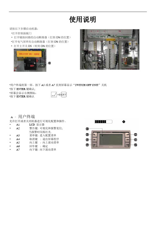
请按以下步骤启动机器: •打开控制面板门 • 打开辅助回路的自动断路器(打到 ON 的位置) •打开电气屏所有自动断路器(打到 ON 的位置) • 打开主开关 D5(转到 ON 的位置)
•用户终端的第一屏,按下 A5 或者 A7 直到屏幕显示“SWITCH OFF UNIT”关机
•按下 ENTER 键确认; •屏幕会显示右侧图标: •按下 ENTER 键确认
压缩机
1.短路保护
复位断路器,检查知足的原因。重新启动压缩机,检 查各绕组的阻抗。
2.接触器不工作
检查接触器连接和接触器线圈
1.缺相
检查压缩机各绕组的阻抗,然后复位,测量电压和相 序。
2.过载
检查压缩机的压力是否超过设计要求。
3.电源电压过高或过低
空调安装手册说明书
MANUAL DE INSTALACIÓNAIRE ACONDICIONADO TIPO INVERTERÍNDICEPRECAUCIONES DE SEGURIDAD (04)ESPECIFICACIONES Y ACCESORIOS (06)RESUMEN SOBRE LA INSTALACIÓN DE LA UNIDAD INTERIOR (07)PARTES DE LA UNIDAD (09)INSTALACIÓN DE LA UNIDAD INTERIOR (10)5.1 SELECCIÓN DE LA UBICACIÓN DE INSTALACIÓN (10)5.2 FIJAR EL SOPORTE DE PARED (11)5.3 PERFORAR LA PARED PARA COLOCAR LAS TUBERÍAS DE CONEXIÓN (12)5.4 PREPARACIÓN DE LA TUBERÍA DEL REFRIGERANTE (14)5.5 CONEXIÓN DE LA TUBERÍA DE DESCARGA (16)5.6 CONEXIÓN DEL CABLE DE COMUNICACIÓN (19)5.7 SUJECIÓN DE TUBERÍAS Y CABLES (21)5.8 MONTAJE DE LA UNIDAD INTERIOR (22)INSTALACIÓN DE LA UNIDAD EXTERIOR (24)6.1 SELECCIÓN DE LA UBICACIÓN DE INSTALACIÓN (24)6.2 INSTALACIÓN DE LA ARANDELA DE GOMA (26)6.3 FIJAR LA UNIDAD EXTERIOR (27)6.4 CONECTAR LOS CABLES DE COMUNICACIÓN Y DE ALIMENTACIÓN (28)INSTALACIÓN DE LA TUBERÍA DEL REFRIGERANTE (31)OBSERVACIONES SOBRE LA LONGITUD DE LA TUBERÍA (31)INSTRUCCIONES DE CONEXIÓN - TUBERÍA DEL REFRIGERANTE (31)7.1 CORTE DE TUBERÍAS (31)7.2 ELIMINACIÓN DE REBABAS (32)7.3 EXTREMOS ABOCARDADOS DE LA TUBERÍA (32)7.4 CONEXIÓN DE LAS TUBERÍAS (34)PURGA DE AIRE (37)INSTRUCCIONES SOBRE LA PURGA (37)OBSERVACIONES SOBRE LA CARGA DE REFRIGERANTE ADICIONAL (39)VERIFICACIONES ELÉCTRICAS Y DE FUGAS DE GAS (40)PRUEBA DE FUNCIONAMIENTO (41)ELIMINACIÓN DE RESIDUOS (43)SoporteFig. 3.11Si va a instalar una unidad sobre el suelo o sobre una plataforma de hormigón, realice lo siguiente:1. Marque las ubicaciones sobre la superficie para colocar cuatro pernos de anclaje para concreto según las especificaciones del cuadro de dimensiones para el montaje de la unidad.2. Realice una perforación para insertar los pernos.3. Limpie el polvo de los agujeros.4. Coloque una tuerca en el extremo de cada perno.5. Martille los pernos en los agujeros previamente perforados.6. Extraiga las tuercas de los pernos y coloque la unidad exterior sobre los pernos de anclaje.7. Coloque una arandela en perno, y luego las tuercas.8. Usando una llave, apriete cada tuerca hasta el tope.ADVERTENCIAAL PERFORAR EL HORMIGÓN, SE RECOMIENDA USAR SIEMPRE PROTECCIÓN OCULAR.Si va a instalar la unidad sobre un soporte de pared, realice lo siguiente:PRECAUCIÓNAntes de realizar la instalación de una unidad sobre la pared, asegúrese de que la pared esté hecha de ladrillos, hormigón o cualquier material de características similares. La pared debe ser capaz de soportar al menos cuatro veces el peso de la unidad.1. Marque las posiciones de los cuatro orificios del soporte , asegúrese que este cumpla con las especificaciones del cuadro de dimensiones para el montaje de la unidad.2. Realice una perforación para insertar los tornillos.3. Limpie el polvo después de realizar los agujeros.4. Coloque una arandela en el extremo de cada tornillo.5. Insertar los pernos de anclaje dentro de los agujeros realizados, coloque el soporte en su posición y golpee con un martillo los pernos en la pared.6. Compruebe que los soportes de montaje hayan quedado nivelados.7. Eleve la unidad cuidadosamente y coloque su base sobre los soportes.8. Atornille la unidad firmemente a los soportes.REDUCIR VIBRACIONES DE LA UNIDAD MONTADA EN LA PAREDSi es posible, puede instalar la unidad para pared con un soporte de caucho para reducir las vibraciones y el ruido.6.4: Conectar los cables de comunicación y de alimentaciónLa bornera de la unidad exterior está protegida por una tapa en el lateral de la unidad. En la parte interior de la tapa se encuentra impreso un diagrama eléctrico general.ANTES DE REALIZAR TRABAJOS ELÉCTRICOS, LEA ESTAS REGLAMENTACIONES1. La instalación eléctrica debe cumplir con las reglamentaciones locales y nacionales vigentesy debe ser llevada a cabo por personal calificado.2. Las conexiones eléctricas deben ser realizadas de acuerdo a las especificaciones delComprobaciones de fugas de gasHay dos métodos diferentes para comprobar si hay fugas de gas.Método de agua y jabónCon un cepillo suave aplique agua jabonosa o detergente líquido en todos los puntos de conexión de las tuberías en la unidad interior y exterior. La presencia de burbujas indica que hay una fuga.Método del detector de fugasSi usa un detector de fugas, consulte el manual de uso del dispositivo para un mejor funcionamiento.LUEGO DE COMPROBAR SI HAY FUGAS DE GASDespués de confirmar que todas las conexiones NO tienen fugas, reinstale la tapa de la válvula en la unidad exterior.PRUEBA DE FUNCIONAMIENTOAntes de llevar a cabo la prueba de funcionamientoSólo realice la prueba de funcionamiento después de haber completado los siguientes pasos:• Comprobaciones de seguridad eléctrica: Confirme que el sistema eléctrico de la unidad sea seguro y funcione.• Comprobaciones de fugas de gas: Compruebe todas las conexiones de la tuerca abocardada y confirme que el sistema no tenga fugas.• Verifique que las válvulas de gas y líquido (de alta y baja presión) estén completamente abiertas.Instrucciones sobre la prueba de funcionamientoLa prueba de funcionamiento se debe realizar durante al menos 30 minutos.1. Conecte la unidad a la electricidad.2. Pulse el botón ON/OFF en el control remoto para encender el equipo.3. Pulse el botón MODE (Modo) para desplazarse a través de las siguientes funciones, una por vez:COOL (refrigeración): Seleccione la temperatura más baja posible.HEAT (calefacción): Seleccione la temperatura más alta posible.4. Deje que cada función permanezca activa durante 5 minutos y lleve a cabo los siguientes chequeos:。
施耐德ATV212变频器快速入门指南(中文)

S1A53831 - 04/2011
4 连接变频器:电源
• 将变频器接地。 • 检查断路器或熔断器的额定值。 • 检查电机电压是否与变频器电压兼容。电机电压 ______V。 • 将变频器连接到电机。 • 将变频器连接到线电源。
ATV212
M3X
200...240 V
或
ATV212
380...400 V N4
出厂设置 0
客户设置
危险
警告
电击或电弧危险
• 在自整定期间,电机以额定电流运转。 • 在自整定期间,请勿维修电机。
不遵守这些说明,则可能会导致严重的人身伤害甚至死亡。
意外的设备操作
• 在开始自整定之前,必须正确配置下列标称电机参数:uLu, uL, F415 和 F417。
• 如果自整定之后,对其中一个或多个参数作了修改,那么 F400 将返 回 0,因而必须重新执行该步骤。
代码 CMOd [ 命令模式 ] F111 [F 端子功能选择 ] F112 [R 端子功能选择 ] F113 [RES 端子功能选择 ]
设置 0 [ 逻辑输入 ] 2 [ 正转 ] 49 [3 线 ] 3 [ 保留 ]
9.2 [ 本地组态 ]
RUN PRG MON
Loc Rem
% Hz
MODE
ENT
[ 电机额定频率 ]: 电机铭牌上的电机额定频率 (Hz)
[ 电机额定电压 ]: 电机铭牌上的电机额定电压 (V)
[ 电机额定电流 ]: 电机铭牌上的电机额定电流 (A)
[ 电机额定速度 ]: 电机铭牌上的标称电机转速 (rpm) [ 电机电流限制 ]: 以限制驱动或制动中的电流(%)
Loc Rem
• 运转控制连接 :
- 1、下载文档前请自行甄别文档内容的完整性,平台不提供额外的编辑、内容补充、找答案等附加服务。
- 2、"仅部分预览"的文档,不可在线预览部分如存在完整性等问题,可反馈申请退款(可完整预览的文档不适用该条件!)。
- 3、如文档侵犯您的权益,请联系客服反馈,我们会尽快为您处理(人工客服工作时间:9:00-18:30)。
LEONARDO INSTALLATION MANUAL
雷纳多安装手册
版本 VERSION: 1.0文
UNIFLAIR 公司奉行技术创新的政策,并保留修改的权利,恕不另行通知。
2
目录
一般说明 ............................................................................ 5 手册包含的信息 ........................................................ 5 提示 ............................................................................ 5 储存 ............................................................................ 5 回收处理 .................................................................... 5
介 绍 ................................................................................ 7 演示系统 .................................................................... 7 雷纳多精密空调有四种机型 .................................... 7 气流方向 .................................................................... 7 上吹机型 ............................................................ 7 下吹机型 ............................................................ 7 机组型号命名方式 .................................................... 8 铭牌 ............................................................................ 8 机器上的警告标志 .................................................... 9 包装上的运输标示 .................................................... 9
R407C................................................................ 21
R410A ............................................................... 22 回液管直径 (LIQUID) .................................... 25 建议搭配的室外机 .......................................... 25 排气管与回液管安装 .............................................. 26 充注制冷剂 .............................................................. 27 压缩机润滑油 .......................................................... 27 冷却水的连接 .......................................................... 28 手动开启或者关闭机器 .......................................... 29 安装和调整 .............................................................. 30 选择风扇电源电压 .......................................... 30 如何调整风扇转速 .......................................... 30 管理设置和安全装置 ...................................... 33 设置进水压力阀 (冷冻水机型可选)............... 33 设置风扇空气压力传感器 FS ...................... 33 设置过滤器脏堵传感器 PFS............................ 33 维护保养 .................................................................. 34 季度检查 .......................................................... 34 半年度检查 ...................................................... 34 年度检查 .......................................................... 34 检修.......................................................................... 35 雷纳多冷冻水机组 .......................................................... 37 技术参数 .................................................................. 37 操作说明 .................................................................. 37 主要零件名称及描述 .............................................. 38 交货检查 .................................................................. 40 卸载机器 .................................................................. 40 安装方面要求 .......................................................... 40 安装机组 .................................................................. 40 开启与拆卸面板 ...................................................... 40 开门 .................................................................. 40 拆卸前面板和侧面板 ...................................... 40 拆卸后面板 ...................................................... 40 内部保护挡板 .................................................. 41 电气连接 .................................................................. 42 排水管连接 .............................................................. 43 冷冻水连接 .............................................................. 43 向回路注水 .............................................................. 43 向主回路注水 .................................................. 43 向调节器注水 .................................................. 43 手动开启或者关闭机器 .......................................... 44 安装和调整 .............................................................. 45 选择风扇电源电压 .......................................... 45 管理设置和安全装置 ...................................... 50
安全提示 ............................................................................ 5 概述 ............................................................................ 5 吊装和搬运的警告 .................................................... 6 安装警告 .................................................................... 6 设计用途 .................................................................... 6 使用警告 .................................................................... 6 使用环境限制 ............................................................ 6 维护期间的安装工作 ................................................ 6