FM2261技术手册
VHF22电台试验器使用说明书

机载电子设备维修测试及故障分析方法编 写: 贺 军中信海直通用航空维修工程有限公司第一章:机载电子设备维修检测基本方法:第一节:检修程序:1、了解情况:1.1、维修人员接收到送检故障件后首先要通过送检故障单,阅读送检设备部件的历史资料等,了解故障现象和分析故障原因,作出初步故障判断。
1.2、按照送检设备件号查询和准备与该部件相符合的维修手册和相关技术资料,准备试验器和检测设备及连接电缆等附件。
1.3、如果送修件不是自己非常熟悉该设备电路原理和已经对该部件很有维修经验的时候,首先要静下心来认真消化该设备部件的维修手册,熟悉该部件整机电路工作原理和认真分析有可能与故障相关的电路。
1.4、按照维修校验规程连接好试验器、检测设备、故障部件。
1.5、按照校验规程检测故障部件,确认送检部件是否与送检故障相符。
2、检查压缩故障点:检查压缩,就是利用静态和动态实施检修的过程。
首先要进行对保险装置的检查,保险装置包括安装在部件上的速熔断保险丝、电源保安反向接入二极管、稳压二极管等进行检查,如有故障首先予以排除,保险装置检查合格后,方可通电检测。
常言道要“通过现象看本质”,检修故障也是如此,要能够顺利的压缩故障点,首先要认真、仔细、全面、准确地观察该部件故障现象,观察看电路板上有没有烧黑损坏的元器件,电路板上有没有异常的地方等,把握了故障现象在理论的指导下,作出正确的分析判断,按照一定的检修原则和方式,便可排除故障点。
3、修复检验:在检查压缩到故障点后,应立即修复,然后要加以检验。
检验的内容包括工艺焊接质量、机械性能和电气技术性能是否合格等。
检验方法应根据具体情况和校验规程条件确定,最简单的故障维修也要经过调整使用、试机,运用测试仪表和试验器进行技术指标检查,以确保主要技术性能指标达到维修手册的要求。
第二节:检修原则:为了正确而有效地实施检修,确保检修质量和安全,迅速修复,必须遵守一定的检修原则。
先思索后动手、先电源配件后机器、先外后内、先静后动、先简(易)后繁(难)、先通病后特殊等,这“六先六后”是每一个机载电子设备维修人员在检修中要遵守的原则。
实训指导手册
西门子 CPU226CN型可编程控制器成套设备实训指导手册(A)亚龙科技集团有限公司前言可编程序控制器(programmable controller)简称PLC,它是美国60年代来在传统的顺序控制器基础上引入微电子技术和计算机技术而研制出的新型工业自动控制装置。
当前,在我国PLC已经广泛应用于钢铁、石油、化工、电力、建材、机械制造、汽车、轻工、交通运输、环保以及文化娱乐等各种行业。
随着工业控制技术的进步,可编程控制器已广泛地应用于工业生产过程的自动控制领域。
为了适应社会的需要,许多大、中专院校已经开设了这方面的课程。
而可编程控制器的应用技术是一门实践性很强的学科,只有通过实际操作,才能较好地掌握这门技术。
为了满足教学的需要,提高教学质量,给老师和学生创造一个理想的实训条件,我公司根据教育部颁的教学大纲,开发了一整套可编程控制器的实训设备。
其中包括可编程控制器主机及六种教学实训模型。
并且提供相应的梯形图和指令表,供学生演示实训。
学生也可以根据教学模型的特点自己设计梯形图和编写程序。
在教学模型的设计上,我公司力争做到,实用性强,可靠性高,形象真实、表现充分,以改过去教学模型的呆板或抽象。
使老师教学更加生动,使学生学习更有趣味,使师生们在使用时感到轻松,方便。
实训主机选用西门子公司生产的S7-200 CPU226CN型PLC,这种PLC结构紧凑、可靠性高、组成灵活、操作方便。
实训演示单元目前开发了交流三相电动机控制、全自动洗衣机控制、步进电机控制、交通信号灯控制、四层电梯控制及电镀自动生产线控制等。
学生通过实训,可以加深理解各种指令的特点及其功能、提高编程技巧、培养学生应用PLC的能力。
本手册共分三部分,第一部分介绍S7-200编程软件的使用,第二部分是编程训练,第三部分介绍PLC的应用实训。
本手册由于编写时间仓促、如有不当之处恳切希望读者批评指正。
目录第一部分 STEP7-MICRO/WIN32编程软件 (1)一、STEP7-M ICRO/WIN32软件的使用 (1)二、STEP7-M ICRO/WIN32简介 (5)三、程序编制及运行 (9)四、实验步骤 (12)五、实验注意事项 (12)第二部分可编程控制器基本指令及实训设备 (13)一、亚龙PLC实训成套设备 (13)二、SIEMENS S7-200可编程控制器简介 (13)三、可编程控制器基本指令训练 (14)第三部分 PLC应用实训 (17)实训一、全自动洗衣机的控制 (17)实训二、三相电动机的顺序控制 (20)实训三、步进电机控制 (23)实训四、交通灯控制 (27)实训五、四层电梯控制 (30)实训六、电镀生产线控制 (34)实训七、水塔水位自动控制 (38)实训八、自控成型机 (41)实训九、自动送料装车系统 (44)实训十、多种液体自动混合 (47)实训十一、自控轧钢机 (50)实训十二、邮件分拣机 (54)实训十三、铁塔之光 (58)第一部分 STEP7-Micro/WIN32编程软件一、STEP7-Micro/WIN32软件的使用1、概述编程软件STEP7-Micro/WIN32 Version 3.1适用于S7-200系列PLC的系统设置(CPU组态)、用于程序开发和实时监控运行;升级版Microwin3.1 SPL扩充了V3.1的功能;Toolbox(工具箱)提供用户指令和触摸屏TP070的组态软件;汉化软件是针对SP1和Toolbox的软件,但不能汉化V3.1及早期版本的软件。
Prosonic M FMU40 HART 超声波物位变送器 操作手册说明书

Products Solutions Services操作手册Prosonic M FMU40HART超声波物位变送器BA01961F/28/ZH/01.22-00715775022022-04-04Prosonic M FMU40 HART2Endress+HauserProsonic M FMU40 HART 目录Endress+Hauser3目录1文档信息 (4)1.1文档功能.............................41.2信息图标.............................41.3补充文档资料.........................51.4注册商标.............................52基本安全指南 (5)2.1人员要求.............................52.2指定用途.............................52.3工作场所安全.........................62.4操作安全.............................62.5产品安全.............................62.6IT 安全..............................63产品描述 (7)3.1产品设计 (7)4到货验收和产品标识 (8)4.1到货验收.............................84.2产品标识.............................84.3制造商地址...........................84.4储存和运输...........................85安装 (9)5.1安装要求.............................95.2测量范围............................135.3安装后检查 (15)6电气连接 (15)6.1接线要求............................156.2连接测量设备........................166.3接线端子分配........................176.4供电电压............................186.5等电势连接..........................186.6连接后检查..........................197操作方式 (19)7.1操作方式概述........................197.2操作菜单的结构和功能.................197.3通过现场显示单元访问操作菜单..........207.4通过调试软件访问操作菜单..............227.5锁定或解锁参数设置...................228系统集成 (23)8.14...20mA HART 通信输出 (23)9调试 (24)9.1功能检查............................259.2启动测量设备........................259.3通过FieldCare 连接 (25)9.4设置测量设备........................269.5显示包络线.. (31)10诊断和故障排除 (33)10.1当前故障............................3310.2历史错误............................3310.3错误类型............................3310.4诊断信息列表........................3410.5应用错误............................3510.6复位测量设备........................3710.7固件更新历史........................3811维护 (38)11.1维护计划 ...........................3811.2维护任务. (39)12维修 (39)12.1概述...............................3912.2Endress+Hauser 服务产品...............3912.3处置. (40)13附件 (40)13.1设备专用附件........................4013.2通信专用附件 (46)14技术参数 (47)14.1输入...............................4714.2输出信号............................4814.3电源...............................4814.4性能参数............................4914.5环境条件............................5014.6过程条件............................5115附录 (51)15.1操作菜单概览 (51)索引 (54)文档信息Prosonic M FMU40 HART4Endress+Hauser1文档信息1.1文档功能文档包含设备生命周期内各个阶段所需的所有信息。
FM2147CMOS漏电保护器电路技术手册.pdf_1694054427.6475008说明书
FM2147CMOS漏电保护器电路技术手册2011. 4本资料是为了让用户根据用途选择合适的上海复旦微电子集团股份有限公司(以下简称复旦微电子)的产品而提供的参考资料,不转让属于复旦微电子或者第三者所有的知识产权以及其他权利的许可。
在使用本资料所记载的信息最终做出有关信息和产品是否适用的判断前,请您务必将所有信息作为一个整体系统来进行评价。
由于本资料所记载的信息而引起的损害、责任问题或者其他损失,复旦微电子将不承担责任。
复旦微电子的产品不用于化学、救生及生命维持系统。
未经复旦微电子的许可,不得翻印或者复制全部或部分本资料的内容。
今后日常的产品更新会在适当的时候发布,恕不另行通知。
在购买本资料所记载的产品时,请预先向复旦微电子在当地的销售办事处确认最新信息,并请您通过各种方式关注复旦微电子公布的信息,包括复旦微电子的网站(/)。
如果您需要了解有关本资料所记载的信息或产品的详情,请与上海复旦微电子集团股份有限公司在当地的销售办事处联系。
商标上海复旦微电子集团股份有限公司的公司名称、徽标以及“复旦”徽标均为上海复旦微电子集团股份有限公司及其分公司在中国的商标或注册商标。
上海复旦微电子集团股份有限公司在中国发布,版权所有。
1 产品简介FM2147是高性能漏电保护器专用电路。
内部包括稳压电源、放大电路、比较电路、跳闸控制器以及跳闸驱动电路。
外围有脱钩线圈、压敏电阻、稳压二极管、二极管、电阻、电容等元器件。
1.1 产品特点l交流供电l直接驱动SCR,当有漏电信号时,OS输出脉宽大于30msl适用于检测A型和AC型漏电信号l各种类型的漏电信号的跳闸精度一致性好l良好的电磁干扰(EMC)防护能力l适用于110V~220V(50 ~ 60HZ)电压l宽的温度范围(Ta=-20~+80℃)1.2 引脚描述引线管脚名说明1 NC 无连接2 In1 放大器输入端13 In2 放大器输入端24 VSS 地线5 OS 跳闸信号输出6 Dly 延迟调整,外接电容7 OA 内部放大器输出,外接滤波电容8 VDD 电源线1.3 极限参数参数值参数名称单位最小值最大值工作温度-20 +85 °C存储温度-55 +150 °C 任何引脚的对地电压-1.0 +7.0 V工作电压8.5 V工作电流8 mA2 功能描述FM2147漏电保护器专用电路用于检测火线和零线上的漏电信号。
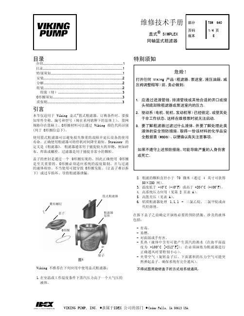
维修技术手册
氟和强 氟化剂
TSM 部分
640 版本 E
页码 3 、 4
问题 盖子很难转动
可能原因 1)系统带压 2)O形圈发胀 3)液体内部粘稠或呈固态
盖子很难安装
粗滤器顶部周围泄 漏液体
4)O形圈发胀 5)O形圈发没有润滑 6)粗滤器体内没有太多液体 7)O形圈被割断 8)O形圈下有异物
有过度压降
如果不遵守上述预防措施、可能导致严重的人身伤害 或死亡。
2. 粗滤的颗粒直径小于 70 微米(通过 4 英寸可获得 50Х250 网)。
3. 温度低于 -40ºC (-40ºF) 或高于 +204ºC (+400ºF)。 4. 高系统压力应用(见第 2 页表 A)。 5. 高篮差压(见表 A)。 6. 铝质粗滤器处理 1,1,1 - 三氯乙烷、二氯甲烷或卤
将粗滤器设置在一个排液塞可以容易拆下的位置(如果要经 常维护、可以用排放阀替代排放塞)。 根据表 A 的要求、粗 滤器上方要有足够的空间用于拆除滤篮。盖式粗滤器上铸有 指示液流方向的箭头。这些粗滤器没有设计任何类型的反洗 操作。
注:不推荐将粗滤器的开口直立安装、因为这样会增加维护 的难度。
如果不遵守上述预防措施、可能导致严重的人身伤害 或死亡。
维修技术手册 部分
盖式® Simplex
页码 版本
同轴篮式粗滤器
TSM 640
1/4 页 E
目录
介绍................................................................................1 目录................................................................................1 特别须知........................................................................1 安装...............................................................................2 分解...............................................................................2 组装...............................................................................2
burster8526 力传感器 技术手册

Dim. tolerances acc. ISO 2768-f
Dimensions [mm] H2 øT N 3 3 3 3 3 3 3 3 3 6 6 øA 7 7 øB 3 3 3 3 3 3 3 4.5 4.5 4.5 4.5 øC 2 2 2 2 2 2 2 3 3 3 3 K 11 11 L 40 40 40 40 40 40 40 40 40 45 45
Electrical values
Bridge resistance (full bridge): foil-model strain gauge 350 Ω, nominal** Excitation: measuring range ≤ 0 ... 1 kN max. 5 V DC measuring range ≥ 0 ... 2 kN max. 10 V DC Output: 1 mV/V ± 0.25 % for ranges to 0 ... 1 kN 1 mV/V ± 0.5 % for ranges from 0 ... 2 kN Calibration resistor: 100 kΩ ± 0.1 %, model 1148-6080 The bridge output voltage resulting from a shunt of this value is stated in the calibration certificate. ** Deviations from the stated value are possible. Resistance between supply lines max. 500 Ω for standardization. Dimensional drawing Model 8526
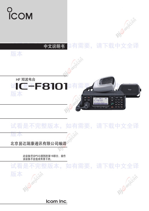
icom if8101 短波车载电台中文说明书
❍ ALE (自适应)/选呼功能 ❍ 数字信号处理器(DSP)可以灵活选择滤波
器。 ❍ 点阵 LCD 显示器可以显示各种信息。
重要事项
操作电台前请仔细阅读本操作手册。
请保存好本手册,该说明书包含了关于IC-F8101的
重要的使用说明。
FCC 信息
• 对于A类通用辐射器:
本设备经测试证明符合FCC规则第15部分中关于A类 数字设备的限制。这些限制是为了在商业环境中操作 设备提供合理的保护,以防止有害干扰。本设备会产 生,使用并辐射射频能量,如果未按照说明手册进行 安装和使用,可能会对无线电通讯产生有害干扰。 在居民区使用此设备可能会造成有害干扰,在这种情 况下,将要求用户自行纠正干扰。
请在张贴告示牌的地方关闭电台。
■ CFU-F8100 (选件风扇) ............... 9
请勿在对电磁辐射敏感的区域(如医院,飞机和爆破场
■ RMK-6 (可分离组件) ..................... 80 ■HM-192 (可遥控麦克风版本)......................... 2
5
■ 模式选择........................................................9
■ VFO操作........................................................10 3 接收和发射.......................... -1
您的Icom无线电设备在发射模式下回产 生RF电磁能量。本电台为“陆地专用短波 电台”,是专业设备。这意味着它只能在 了解危害的人员,以及了解这种危害的人
员的使用。一般人群须经过培训使用。
ROA 117 2261 音频 ALc 模块维护手册说明书
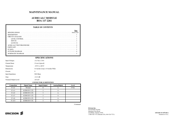
MAINTENANCE MANUAL AUDIO ALC MODULEROA 117 2261ContinuedSPECIFICATIONSInput V oltages +12 Vdc ± 10%Current Drain 23 mA (typical)Temperature -30°C to +60°CDimensions 8.0 inches Long x 4.0 inches Wide Circuits 6Input Impedance 600 Ohms Gain+12.5 dB Nominal Output Level245 mVeEricsson Inc.Private Radio System Mountain View RoadLynchburg, Virginia 24502AE/LZB 119 1878 R1A1-800-528-7711 (Outside USA, 804-528-7711)Printed in U.S.A.DESCRIPTIONAudio Automatic Level Control (ALC) module ROA 117 2261 provides clear voice audio processing for six inde-pendent audio channels in GPS Simulcast Systems (Figure 1). The ALC Module is designed for “transparent” (0 dB gain, 0 dB loss) operation at the normal system level of -10dBm, and to maintain this -10 dBm output level with in-put fluctuations of ±10 dB or more (gain is limited to 12.5dB). The response to input fluctuations has a time constant of 10 mSec.Each input is transformer coupled (T1-T6) and expects a 600 ohm balanced line. The output is single ended, low im-pedance, intended to drive several audio distribution module inputs in parallel.ALC modules plug into Control Point Sync Shelf slots 15 - 18 (Refer to Maintenance Manual AE/LZB 119 1903).The module in slot 15 performs ALC for Simulcast channels 1, 5, 9, 13, 17 & 21. The module in slot 16 performs ALC for Simulcast channels 2, 6, 10, 14, 18 & 22. The module in slot 17 performs ALC for Simulcast channels 3, 7, 11, 15,19 & 23. The module in slot 18 performs ALC for Simulcast channels 4, 8, 12, 16, 20 & 24.CIRCUIT ANALYSISLEVEL CONTROLThe circuitry is based on dual gain control circuit SA571and is a standard application of that part. Resistors R1 - R6are chosen to provide a maximum gain of 12.5 dB. Resistors R7 - R12 set the output level to -10dBm. Each IC package contains two functional units, so that three IC’s (U1-U3) are sufficient for 6 voice paths. The module operates from a standard +5 Vdc supply, with on-board automatic thermister fuse F1 to prevent collapsing the supply in the event of a failure.INPUTSInputs for each of the six (6) channels come from voters in the voting self. The balanced pair input for each of 6channels is on connectors:AUDIO IN 1 is on:J1 - A3 (T ip)J1 - C3 (R ing)AUDIO IN 2 is on:J1 - A5 (Tip)J1 - C5 (Ring)AUDIO IN 3 is on:J1 - A7 (Tip)J1 C7 (Ring)AUDIO IN 4 is on:J1 - A9 (Tip)J1 - C9 (Ring)AUDIO IN 5 is on:J1 - A11 (Tip)J1 - C11 (Ring)AUDIO IN 6 is on:J1 - A13 (Tip)J1 - C13(Ring)OUTPUTSAudio outputs from the ALC Module are sent to an Audio Distribution Module located in the Audio Distribu-tion Shelf for further processing.Rows A, B & C of the ALC Module are connected in parallel to maintain low impedance and improve circuit in-tegrity as follows:AUDIO OUT 1 is on:J1 - A19, B19, C19AUDIO OUT 2 is on:J1 - A21, B21, C21AUDIO OUT 3 is on:J1 - A23, B23, C23AUDIO OUT 4 is on:J1 - A25, B25, C25, AUDIO OUT 5 is on:J1 - A27, B27, C27AUDIO OUT 6 is output on: J1 - A29, B29, C29Copyright© September 1996, Ericsson IncContinuedThis manual is published by Ericsson Inc., without any warranty. Improvements and changes to this manual necessitated by typographical errors, inaccuracies of current information, or improvements to programs and/or equipment, may be made by Ericsson Inc., at any time and without notice. Such changes will be incorporated into new editions of this manual. No part of this manual may be reproduced or transmitted in any form or by any means, electronic or mechanical, including photocopying and recording, for any purpose, without the express written permis-AE/LZB 119 1878 R1A1Figure 1 - Front PanelAUDIO ALC TEST PROCEDURE Equipment Required:• + 12 Vdc Power Supply• Multimeter (V olt/Ohmmeter)• Function Generator (Sin Wave)Continuity Test:Using the multimeter, check for a short circuit between Power (+12 Vdc and ground)Procedure:1. Apply +12 Vdc Power to the power pin C31 andground Pin A1, B1 and C12. Check all ground and power pin connectors:Power: C31Ground: A1, B1, C1, A32, B32, C323. Using a 1000 Hz test tone, vary the voltages onthe inputs and check and record the output voltage.The corresponding output voltage should be 245 mV±50 mV.AE/LZB 119 1878 R1A 2PARTS LIST & IC DATA*COMPONENTS ADDED, DELETED OR CHANGED BY PRODUCTION CHANGESAUDIO ALC MODULEROA 117 226118916101112131415234567U1-U3Dual Gain Control CircuitRYT 101 6005/C (SA 571)AE/LZB 119 1878 R1A3AE/LZB 119 1878 R1AOUTLINE DIAGRAMAudio ALC Module(1078 ROA 117 2261, Rev. A)4AE/LZB 119 1878 R1A SCHEMATIC DIAGRAMAudio ALC Module(1911 ROA 117 2261/1, Rev. A)5。
柯顿2110背负式短波电台中文版技术手册

这就意味着用户不再需要备用电池以减轻用户出行重量。 语音加密功能
为了其他安全方面的考虑,2110 对传送信息及位置信息也是加密的。可确保语音信息传输安全。 抗震、抗毁性能符合 MIL-STD-810F 指
标 可以在恶劣的坏坏境中工作。 防水性能好
2110 提供的防水连接头,包括手咪话筒,扬声器,按键以及扩展的数据端口等等。可浸没在 1 米深
酶菌:
MIL-STD-810F,Method 508.5
盐雾:
MIL-STD-810F,Method 509.4,Procedure 1
沙尘:
MIL-STD-810F,Method 510.4,Procedure 1
MIL-STD-188-141B(要求 ALE)
串口 RS-232,红外线(IrDA)
湿度:
MIL-STD-810F,Method 507.4
振动(3 小时/每个轴向): MIL-STD-810F,Method 514.5
冲击:
MIL-STD-810F,Method 516.5,Procedure 1
密封(浸没):
MIL-STD-810F,Method 512.4,Procedure 1
发射 1.6 到 30 MHz;接收 250 kHz 到 30 MHz
400 个信道,10 个网络组
600 个信道,20 个网络组(符合军标 MIL-STD-188-141B ALE)
单边带(J3E)USB,LSB;可选 USB,LSB;AM(H3E);CW(J2A);AFSK(J2B)
±1.5ppm 或±0.5ppm(-30 到+60℃)
的水中而不损坏。 重量轻
2.5 公斤,电台和电池外壳采用超轻合金及超性能工程塑料制成。是当今世界上最轻,经过认证的
FM166 快速调节模块使用说明书

1 2
汽轮机数字电液调节系统,是英文 Digital Electro-Hydraulic Control System 的简称。 线性可变差动传感器,一种直线行程传感器,是英文 Linear Variable Differential Transducer 的简称。 HollySys
2
HOLLYSYS
1.2 组成
FM166 模块主要由快速调节模板和外壳结构 件 组 成 。 使 用 时 , FM166 模 块 需 要 与 端 子 底 座 FM131A 相连,构成完整的快速调节模块。其外观 如图 1-1 所示: FM166 模块正面标签夹中可以插入纸卡,纸卡 上可以写上输入输出通道的测点名称或标识,便于 工程使用及维护。纸卡的插入方式见图 1-2 所示: FM166 模块采用模块化结构,模块的工作电源 为 24VDC。
HollySys
块式I/O
FM166 快速调节模块
1 基本说明
1.1 简介
FM166 模块是 FM 系列硬件产品中的 DEH 快速调节模块, 与底座 FM131A 配合使用接收 3 路压 力反馈信号经过三取中电路后,与 1 路给定信号比较,偏差值经过比例调节或比例微分调节等运算 处理后,输出并控制调节阀等执行机构,实现转速微分调节和快速压力调节等功能。
FM166
图 1-1 FM166 模件外观图示
HollySys
PER
DEH PFR
1
快速调节模块
FM166
FM166
RUN
图 1-2 FM166 模件纸卡插入图示
2 原理说明
转速微分调节
FM166 快速调节模块可以与 FM163E 测速保护模块配合使用,实现转速微分调节功能。 将 3 块 FM163E 模块的微分输出信号(0~5VDC)作为反馈信号输入到 FM166 模块,系统稳 定运行时,当机组转速微分信号(即加速度)为零,3 路微分信号输入经过三取中电路后,其中间 值与输入偏差电压相减后的偏差电压为零。当机组转速微分信号(即加速度)为正时,输出控制信 号使调节阀在原有开度的基础上关小一定幅度,反之在原有开度的基础上开大一定幅度。比例调节 放大倍数的大小可在现场根据需要调整。 当与 FM146 系列 DEH1伺服模块配合时,FM166 模块的输出控制信号通过 FM146 系列模块的 1 路的 LVDT2直流电压通道输入,用于调节阀门开度。 当系统未配置伺服模块时,需要由主控单元计算出的总阀位信号,并通过模拟量输出模块将总 阀位信号转换为 4~20mA 标准电流信号,输入到 FM166 模块的位置信号通道,再与转速微分调节 信号相加,之后将输出控制信号直接输出到各种电液转换器控制油动机行程。 输出控制电路可根据需要选择采用恒压输出方式,并且可以根据需要调整输出偏置。
FM系列硬件系统手册

PROFIBUS-DP 总线及设备 ................................................................................................. 31
Profibus-DP 总线简介 ......................................................................................................................... 31
1993-2004 Copyright Hollysys
和利时、HollySys、HOLLiAS 及
的商标或注册商标。
的字样和徽标均为和利时系统工程股份有限公司
Microsoft、Windows 和 WindowsNT 是微软公司在美国和/或其他国家分支机构的商标或注册商 标。
手册中涉及到的其他商标或注册商标属于他们各自的拥有者。
供电系统及接地要求.......................................................................................................................... 20
供电系统说明........................................................................................................................................................... 20 接地要求................................................................................................................................................................... 21
atc中文手册
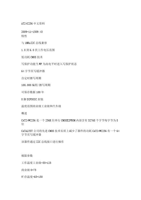
AT24C256中文资料2009-11-1509:43特性与1MHzI2C总线兼容1.8到6.0伏工作电压范围低功耗CMOS技术写保护功能当WP为高电平时进入写保护状态64字节页写缓冲器自定时擦写周期100,000编程/擦写周期可保存数据100年8脚DIPSOIC封装温度范围商业级工业级和汽车级概述CAT24WC256是一个256K位串行CMOSE2PROM内部含有32768个字节每字节为8位CATALYST公司的先进CMOS技术实质上减少了器件的功耗CAT24WC256有一个64字节页写缓冲器该器件通过I2C总线接口进行操作极限参数工作温度工业级-55+125商业级0+75贮存温度-65+150各管脚承受电压-2.0VVcc+2.0VVcc管脚承受电压-2.0V+7.0V封装功率损耗Ta=251.0W焊接温度(10秒)300口输出短路电流100mA功能描述CAT24WC256支持I2C总线数据传送协议I2C总线协议规定任何将数据传送到总线的器件作为发送器任何从总线接收数据的器件为接收器数据传送是由产生串行时钟和所有起始停止信号的主器件控制的CAT24WC256是作为从器件被操作的主器件和从器件都可以作为发送器或接收器但由主器件控制传送数据发送或接收的模式管脚描述SCL串行时钟CAT24WC256串行时钟输入管脚用于产生器件所有数据发送或接收的时钟这是一个输入管脚SDA串行数据/地址双向串行数据/地址管脚用于器件所有数据的发送或接收SDA是一个开漏输出管脚可与其它开漏输出或集电极开路输出进行线或wire-ORWP写保护当WP脚连接到Vcc所有内存变成写保护只能读当WP引脚连接到Vss或悬空允许器件进行读/写操作A0A1器件地址输入这些管脚为硬连线或者不连接对于单总线系统最多可寻址4个CAT24WC256器件参阅器件寻址当这些引脚没有连接时其默认值为0I2C总线协议I2C总线协议定义如下1只有在总线空闲时才允许启动数据传送2在数据传送过程中当时钟线为高电平时数据线必须保持稳定状态不允许有跳变时钟线为高电平时数据线的任何电平变化将被看作总线的起始或停止信号起始信号时钟线保持高电平期间数据线电平从高到低的跳变作为I2C总线的起始信号停止信号时钟线保持高电平期间数据线电平从低到高的跳变作为I2C总线的停止信号器件寻址主器件通过发送一个起始信号启动发送过程然后发送它所要寻址的从器件的地址8位从器件地址的高5位固定为10100见图5接下来的2位A1A0为器件的地址位最多可以连接4个器件到同一总线上这些位必须与硬连线输入脚A1A0相对应从器件地址的最低位作为读写控制位1表示对从器件进行读操作0表示对从器件进行写操作在主器件发送起始信号和从器件地址字节后CAT24WC256监视总线并当其地址与发送的从地址相符时响应一个应答信号通过SDA线CAT24WC256再根据读写控制位R/W的状态进行读或写操作应答信号I2C总线数据传送时每成功地传送一个字节数据后接收器都必须产生一个应答信号应答的器件在第9个时钟周期时将SDA线拉低表示其已收到一个8位数据CAT24WC256在接收到起始信号和从器件地址之后响应一个应答信号如果器件已选择了写操作则在每接收一个8位字节之后响应一个应答信号当CAT24WC256工作于读模式时在发送一个8位数据后释放SDA线并监视一个应答信号一旦接收到应答信号CAT24WC256继续发送数据如主器件没有发送应答信号器件停止传送数据并等待一个停止信号写操作字节写在字节写模式下主器件发送起始信号和从器件地址信息R/W位置0给从器件在从器件送回应答信号后主器件发送两个8位地址字写入CAT24WC256的地址指针主器件在收到从器件的应答信号后再发送数据到被寻址的存储单元CAT24WC256再次应答并在主器件产生停止信号后开始内部数据的擦写在内部擦写过程中CAT24WC256不再应答主器件的任何请求页写在页写模式下单个写周期内CAT24WC256最多可以写入64个字节数据页写操作的启动和字节写一样不同在于传送了一字节数据后主器件允许继续发送63个字节每发送一个字节后CAT24WC256将响应一个应答位且内部低6位地址加1高位地址保持不变如果主器件在发送停止信号之前发送大于64个字节地址计数器将自动翻转先前写入的数据被覆盖当所有64字节接收完毕主器件发送停止信号内部编程周期开始此时所有接收到的数据在单个写周期内写入CAT24WC256应答查询可以利用内部写周期时禁止数据输入这一特性一旦主器件发送停止位指示主器件操作结束时CAT24WC256启动内部写周期应答查询立即启动包括发送一个起始信号和进行写操作的从器件地址如果CAT24WC256正在进行内部写操作将不会发送应答信号如果CAT24WC256已经完成了内部写操作将发送一个应答信号主器件可以继续对CAT24WC256进行下一次读写操作写保护写保护操作特性可使用户避免由于不当操作而造成对存储区域内部数据的改写当WP管脚接高时整个寄存器区全部被保护起来而变为只可读取CAT24WC256可以接收从器件地址和字节地址但是装置在接收到第一个数据字节后不发送应答信号从而避免寄存器区域被编程改写读操作CAT24WC256读操作的初始化方式和写操作时一样仅把R/W位置为1有三种不同的读操作方式立即/当前地址读选择/随机读和连续读立即/当前地址读的地址计数器内容为最后操作字节的地址加1也就是说如果上次读/写的操作地址为N则立即读的地址从地址N+1开始如果N=E此处E=32767则计数器将翻转到0且继续输出数据CAT24WC256接收到从器件地址信号后R/W位置1它首先发送一个应答信号然后发送一个8位字节数据主器件不需发送一个应答信号但要产生一个停止信号选择/随机读选择/随机读操作允许主器件对寄存器的任意字节进行读操作主器件首先通过发送起始信号从器件地址和它想读取的字节数据的地址执行一个伪写操作在CAT24WC256应答之后主器件重新发送起始信号和从器件地址此时R/W位置1CAT24WC256响应并发送应答信号然后输出所要求的一个8位字节数据主器件不发送应答信号但产生一个停止信号连续读连续读操作可通过立即读或选择性读操作启动在CAT24WC256发送完一个8位字节数据后主器件产生一个应答信号来响应告知CAT24WC256主器件要求更多的数据对应每个主机产生的应答信号CAT24WC256将发送一个8位数据字节当主器件不发送应答信号而发送停止位时结束此操作从CAT24WC256输出的数据按顺序由N到N+1输出读操作时地址计数器在CAT24WC256整个地址内增加这样整个寄存器区域在可在一个读操作内全部读出当读取的字节超过E此处E=32767计数器将翻转到零并继续输出数据字节。
欧文诊断文件:欧文移动通信设备 M-RK 896-941MHz 个人双向无线电综合设备维修手册说明书
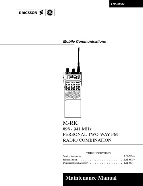
Mobile CommunicationsM-RK896 - 941 MHzPERSONAL TWO-WAY FM RADIO COMBINATIONTABLE OF CONTENTSService Assemblies . . . . . . . . . . . . . . . . . . . . . . . . LBI-38746 Service Section . . . . . . . . . . . . . . . . . . . . . . . . . . LBI-38739 Disassembly and Assembly . . . . . . . . . . . . . . . . . . . . LBI-38741LBI-38837Copyright © December 1992, Ericsson GE Mobile Communications Inc. iiSPECIFICATIONSSYSTEMFCC Identification Number AXATR-204-AFrequency RangeTransmit :Receive :896 - 902 MHz 935 - 941 MHz 935 - 941 MHz Frequency Stability 1.5 ppm Input V oltage 7.5 Vdc (nominal)Battery LifeHigh Capacity6.5 hours at 5-5-90 duty cycleLBI-38837iiiLBI-38837SPECIFICATIONS(Continued)176.8x68x40.6 mm (7x2.7x1.6 inches)Dimensions (HxWxD)(M-RKII)(with high capacity battery)20.3 ouncesWeight (M-RKII)(with high capacity battery)Operable Temperature Range-30º to +60ºC (-22º to +140ºF)TRANSMITRF Power Output0.5 to 3 wattsSpurious Emissions-55dBcMaximum Deviation±2.5ΚΗzFM Hum & Noise-45 dBAudio Distortion3% (60% Modulation)Frequency Stability 1.5 ppm (-30ºC to +60ºC)RF Load Impedance50 ohmsMicrophone Sensitivity Less than 90 dB SPL (EIA 60% M0D)Maximum Attack Time25 milliseconds (PTT Pushed)Audio Frequency Response Within +1 and -3 dB of a 6 dB/octave pre-emphasis from 300Hz to 3000 Hz.RECEIVESensitivity (12 dB SINAD)-116 dBmSpurious Emissions-57 dBmSpurious Response72 dB (minimum)Selectivity70 dB (25 KHz)Squelch Sensitivity 6 dB SINADDistortion (EIA 0.5 watt)5%Audio Frequency Response Within +1 and -3 dB of a 6 dB/octave de-emphasis from 300Hz to 3000 Hz.ivDESCRIPTIONThe ERICSSON GE M-RK Personal Radio is a high-quality, high-performance FM radio. The radio is synthe-sized and operates in both trunked and conventional communication systems. The trunked mode allows selection of either a communications group or an individual radio within a system. Both the selected group and the individual radio are secured through digital signaling.In the conventional mode, the user selects a channel and directly communicates on that channel. A channel is a trans-mit/receive radio frequency pair.A group consists of several users with a common group identification (ID). A radio may have several groups, but the selected group determines who the unit can call at any spe-cific time. In the trunked mode, a set of groups which com-municate on a set of channels is called a system. In the con-ventional mode, a system is a set of channels. A system may consist of all trunking groups and channels, all conventional channels, or a mixture of both.The M-RK Personal Radio is designed to operate in a M-RK Digital Trunking System or as a conventional radio providing the following features.In trunked mode :•Programmable Multiple System Capability -- Theradio can operate on different trunked sites or ondifferent systems at the same site.•Multiple Group Capability -- The radio cancommunicate on several Groups within one trunkedsystem.•Group Call -- The M-RK has the capability ofsimultaneously calling all units within a group.•Programmable Carrier Control Timer -- Personalityinformation includes an optional period of transmittime from 15 to 120 seconds. After the timer expires,the unit will automatically unkey and provide an alerttone. This feature is re-initiated on every PTT and thealert tone is removed upon release of the PTT.•Minimum V olume Level -- Personality informationincludes a minimum volume level.•Programmable Squelch -- The noise squelch openingthreshold can be programmed for each channel.•Receive Mode Lock Out -- In normal trunkedoperation, the radio will not transmit while in thereceive mode.•Automatic Power Levels -- The desired power levelon each channel can be programmed into the radiopersonality. Power level is automatically selected dependent on the channel.•Emergency Feature -- An emergency group can be programmed into the radio. This group is selected by pressing the EMR button. This allows a user to quickly reach this group and initiate the M-RK emergency signalling.•Simple Remote Control Capability -- A speaker/microphone (which can also control PTT and the volume level) can be connected through the UDC (Universal Device Connector).•Surveillance Feature -- The display backlighting may be programmed on or off per group. The side-tone beep, related to the operation of the radio controls, is also capable of being disabled on a group-by-group basis.•Programmable through UDC -- The entire person-ality of the radio is programmed through four con-nections of the UDC.•16 Character Dot Matrix Alphanumeric Crystal Display -- This display is used to exhibit the condition of the radio. It shows channel designation, Channel Guard or Digital Channel Guard on/off, transmit mode, volume level, battery condition, channel busy, and high/low power output.In conventional mode :•16/128-Channel Capability -- Channel designation can be a mixture of numerics (0-128) and alphanumerics displayed through the LCD. Channel control can come from the channel rotary switch, the emergency channel feature, or the front keypad.•Programmable Multi-Tone Channel Guard (CTCSS) Encode/Decode --Channel Guard tone frequencies within the range of 67 Hz to 210.7 Hz, including all of the standard EIA frequencies, may be program-med. Different encode/decode, encode only, and with/without Channel Guard frequencies are also pro-grammable into the radio.•Programmable Multi-Code Digital Channel Guard (CDCSS) Encode/Decode -- Similar capability as with Tone Channel Guard is provided.•Programmable Talkaround Capability -- The ability to switch the transmit frequency from a repeater frequency to a direct communications frequency.•Channel-Busy Lock Out -- Personality information includes the capability to prevent the transmitter from operating on a channel where carrier activity is present. The channel busy indicator (BSY) is active during this time.LBI-388371LBI-38837Figure 1 - M-RK I Controls and Accessories 2LBI-38837Figure 2 - M-RK II Controls and Accessories3Physically an M-RK radio consists of three main printed wire board assemblies and a battery pack as follows :a. A printed wire board specially shielded with zincalloy on which the radio assembly (transmit/re-ceive/synthesizer) is assembled.b. A Control board containing the microprocessor.c. A LCD/KB Flex wire board with displayprocessor,rotary switch, AF volume with switch.d. A battery pack that fits the M-RK main unit.e.Lightweight plastic front and back housing.RADIO ASSEMBLY TRANSMIT CIRCUITThe transmit circuit consists of four major circuits as follows :a.Wide Band Multiplier -- Multiplies the signal fromthe frequency synthesizer.b.Wide Band Power Amplifier -- Amplifies the out-put signal of the multiplier to the desired outputlevel for transmission (a gain of 36.5 dB).c.Wide Band Power Control Circuits -- Can reducethe transmitter output level by 10 dB.d.LPF, DC, Switch Hybrid Module -- Consists ofLPF and directional coupler and Tx/Rx switch.The transmitter completely covers the band within the split. No adjustments are needed except for the RF power control voltage from the controller.RECEIVE CIRCUITThe receiver consists of three major circuits as follows :a.Front-End Circuit -- Consists of a one stage pre-amplifier (with band-pass filters).b.First Mixer and IF circuit -- A special double bal-anced mixer is used to convert the incoming signalto 55.025 MHz first IF. This is put through a band-pass filter (BPF) and an IF amplifier to get the de-sired first IF signal.c.Second IF (455 KHz) -- Consists of one IC andthree BPF containing the second mixer, the secondIF amplifier, and the FM detector. The second IFoutput provides the Logic section with audio out-put.FREQUENCY SYNTHESIZERThe frequency synthesizer is made up of three major modules as follows :a.VCO Module -- The 900 MHz band frequencysynthesizer has one common VCO (450 MHZ) forboth transmitting and receiving. The transmitter ismodulated at both the VCO and the VCTCXO.b.VCTCXO Module -- The VCTCXO is a voltagecontrolled, temperature compensated crystal oscil-lator providing 13.2 MHz as a reference frequencywith modulation capability.c.Phase-Lock Loop -- Consists of a frequency di-vider and a low current drain CMOS IC for phasecomparison.LOGIC CIRCUITThe logic circuit consists of a control board assembly with an audio processor and a LCD/KB Flex assembly as follows :a.Control Board Assembly -- Carries two microproc-essors, RAM, Flash E2PROM, audio proces-sor,digital processor and I/O interconnections withthe frequency synthesizer. This board commandsall the functions and operation of the M-RK radio.b.Audio Signal Processor (ASP) -- Includes trans-mitter and receiver audio circuits.c.Digital Signal Processor (DSP) -- Includes a mo-dem, address decoder, and clock control circuit.d.LCD/KB Flex Assembly -- Includes LCD driverand processor for the display and rotary switch andAF volume with ON/OFF switch.LBI-38837 4SYSTEM ANALYSISRefer to Figures 3, 4 and 5. The M-RK radio consists of three printed wire boards as follows :•Radio Board Assembly -- carries the transmit,receive, and frequency synthesizer circuits.•Control Board Assembly -- supports logic controlcircuits.•LED Flex Assembly carries LEDs (M-RK I).•LCD/KB Flex Assembly -- carries LCD ( M-RK II ).Interconnection of the control board with other boards and control circuits is made with flexible circuit boards and connectors.Circuit illustrations shown are simplified representatives of actual circuits.They are intended only to illustrate basic circuit func-tions.RADIO BOARD ASSEMBLYTransmit CircuitsThe M-RK transmit circuit, as shown in Figures 6 and 7, consists of the following integrated circuit, modules.•Power Amplifier (PA)•LPF/DC/TR SWFigure 3 - Radio Block DiagramLBI-388375LBI-38837Figure 4 - Logic Block Diagram (M-RK I) 6Figure 5 - Logic Block Diagram (M-RK II)Power Amplifier Module (U7)Power Amplifier (PA) U7 is a five-stage, wideband am-plifier module with an input and an output impedance of 50ohms (Figure 6). The first stage of the PA module has the dc power supplied by power set transistor Q203. The RF power output from multiplier is connected through a HPF to pin 1 of the PA module where it is applied to the input of the RF power amplifier stages. The RF power amplifier stages amplify the input from the Tx-Amp module to a typi-cal power output level of 4.5 watts at pin 5. The output at pin 5 is connected through the HPF and LPF/DC/SW mod-ule. A minimum power level of three watts is on the output of the LPF/DC/SW module.LPF/DC/TR SW Module (U8)The output of the PA module is connected LPF/DC/SW through HPF. The FN network is a passive LC low-pass fil-ter with an insertion loss of less than 1.4 dB in the pass-band. It also has a rejection greater than 35 dB in the stop band. The output of the FN connected to the system antennaor to the UDC connector.Receive CircuitThe M-RK receive circuit, as shown in Figures 8, 9 and 10, consists of the following circuits :•RF Amplifier/Mixer•First IF Amplifier•Second IF Amplifier/Discriminator RF Amplifier/MixerThe RF Amplifier/Mixer circuit (Figure 8) contains two third-order band-pass filters (FL301 and FL302), and RF amplifier circuit (Q301) and a double-balanced diode mixer circuit (Z2). RF from the antenna or UDC connector is cou-pled through LPF/DC/TR SW module to the input of the RF amplifier circuit. The RF signal on the input of the RF am-plifier is first coupled through band-pass filter FL301 to the input of grounded emitter broad-band RF amplifier transis-tor Q301. This amplifier provides 13 dB of power gain to reduce thermal noise. The output of the RF amplifier is cou-pled through band-pass filter FL302 to drive double bal-anced mixer circuit Z2.The RF signal from the RF amplifier and the injection frequency from the synthesizer circuit, provide a 55.025MHZ IF on the output of the mixer. The double-balanced Mixer has a typical conversion loss of 7.5 dB between the RF input and IF output. All inputs and the output of the RF Amplifier/Mixer have 50 ohms matching impedance. The +7 dBm injection frequency level, provided by the synthe-sizer and amplifier circuit transistor Q103, is connected to the injection frequency input. The output of the Mixer cir-cuit is connected to the input of the first IF Amplifier.Figure 6 - Power Amplifier (PA)Figure 7 - LPF DC T/R SW. Module (U8)Figure 8 - RF Amplifier/MixerFirst IF AmplifierThe first IF amplifier contains a amplifier circuit and two crystal filters of two poles, respectively (refer to Figure 9). The first IF signal (55.025 MHz) connects to the input of preamplifier transistor Q302 through pre-crystal filter FL303 with an impedance of approximately 3 Kohms. Pre-amplifier Q302 provides a 23 dB power gain. The output is connected to the input of IF amplifier IC U11 through crys-tal filter FL304.Second IF Amplifier/Discriminator (U11)The Second IF Amplifier/Discriminator circuit (Figure 10) contains FM IF IC U11 (TA31132F) and 455 KHZ ce-ramic filter FL305, FL306, FL307. The FM IF IC contains a local oscillator, mixer, IF amplifier, FM detector, and an audio amplifier. The 55.025 MHz IF output from the first IF amplifier is connected to the input of second IF amplifier U11 pin 21 of TA31132F and converted to the second IF frequency (455 KHz). The second IF output is connected to pin 7 input of TA31132F through the 455 KHz ceramic fil-ter to the IF amplifier and FM detector circuits. The recov-ered audio from the FM IF IC is connected to J1-3B.Synthesizer CircuitThe Synthesizer circuit (Figure 11) contains Phase-Lock-Loop (PLL) module U2, VCTCXO Reference Oscil-lator module Z1, TX/RX V oltage Controlled Oscillator (VCO) module U5, and a Low-Pass-Filter (LPF) amplifier.The VCO used to generate the receive and transmit frequen-cies is locked to a stable VCTCXO reference oscillator through a PLL. This feed-back loop divides the VCO fre-quency down to a signal in the range of 3.5 MHz. This sig-nal is divided with a programmable divider to 6.25 KHz,and generates a VCO control signal by comparing the 6.25KHz feedback with a 6.25 KHz signal derived by dividing a 13.2 MHz VCTCXO by 2112 As the least-significant bit in the programming is changed, the VCO is forced to change by 6.25 KHz.The synthesizer circuitry is contained on two modules,the VCO module U5 and the VCTCXO reference oscillator module Z1.Phase-Lock-Loop Module (U2)The PLL module U2 contains a reference frequency, di-vider, phase detector, and a programmable divider. The phase detector dc voltage output signal is filtered with a passive low-pass filter followed by a 6.25 KHz filter to re-duce the level of reference modulation on the VCO. This dc output represents the error between the VCO frequency (phase) and the reference (VCTCXO) and is applied to the VCO on frequency. A lock-detect output is developed from pin 9 of U2. The output is "AND"ed with the TX-PTT out-put from the microcomputer to prevent transmisssion beforethe VCO is on frequency.Figure 9 - First IF AmplifierFigure 10 - Second IF Amplifier/DiscriminatorFigure 11 - SynthesizerSerial data from the microcomputer is shifted into the PLL to set the division parameter which establishes the fre-quency. A clock signal is provided on another input and the data is latched with the enable input.Voltage-Controlled Oscillator (U5)The VCO uses a low-noise, high-gain transistor as the basic oscillator. The resonant circuit, which determines the frequency of oscillation, is formed by a high-Q SAW which is used to set the center frequency at the factory. The output of the VCO is coupled into a cascade amplifier which pro-duces 0 dBm. The output of the RX-VCO amplifier is cou-pled into the receive first double-balanced mixer circuit Z2 through multiplier Q103. The VCO amplifier output is also connected to the input of TX-multiplier transistor Q104. VCTCXO Reference Oscillator (Z1)The Z1 oscillator module is self contained, fully tem-perature compensated and operates at a frequency of 13.2 MHz. The oscillator also has modulation capability. Fre-quency is adjusted by a trimmer while monitoring the trans-mit circuit output at the antenna jack.LOGIC CIRCUITThe logic circuit consists of control circuits and audio circuits (Figures 4 and 5 ).Physically, this circuit consists of two circuit board as follows :•Control Board Assembly•LED Flex Assembly (M-RK I)•LCD/KB Flex Assembly ( M-RK II)Control Board AssemblyThe Control board consists of the following circuits (re-fer to Figures 4 and 5 ) :•CMOS Microprocessor (U1, U2)•E2PROM (U6)•Flash E2PROM (U4)•Custom CMOS DSP Chip (U3)•Custom CMOS ASP Chip (U7)•CMOS Inverters (U12)•CMOS OR gates (U15)•CMOS SRAM (U5)•Audio Amplifier (U11)• 5 volt Regulator (U9,10)MicrocomputerThe main microcomputer circuit in this radio consists of microprocessor, HD6475328FI10 (U2), 2 Kx8E2PROM (U6), 128 K x 8 Flash EPROM (U4), 8 K x 8 RAM (U5), and custom DSP (U3). This circuitry runs at a 9.8304 MHz rate determined by crystal Y1 and controls the radio through a second microprocessor HD6473308FI6 (U1). This micro-processor (U1) runs at an 4.9152 MHz rate. The 4.9152 MHz rate is determined by DSP (U3).•Controlling the DSP, Flash E2PROM and RAM•Loading data to the frequency sysnthesizer•Fetching and processing the PTT, monitor, channelselection, and volume control.•Controlling the LED display (M-RK I).•Loading data to the LCD display processor (M-RKII).•Controlling the audio circuit (processor)•Decoding the squelch•Encoding/Decoding the Channel Guard and DigitalChannel Guard•Controlling the loading interface for the radio data(channel number andsignaling)Flash E2PROM (U4)IC U4 contains the software to control the microproces-sor.RAM (U5)This RAM has a storage capacity of 8 Kbits x 8.E2PROM (U6)This E2PROM has a storage capacity of 2 Kbit x 8. This personality controls various functions of the radio. The per-sonality data is entered from outside the radio through the UDC connector to the microprocessor and then to the E2PROM. The data mainly consists of the following :•Channel Frequency Data•CG/DCG data•TX Power, TX Modulation Data•Squelch Data•Display Data, etc.Digital Signal Processor (DSP)(U3)The primary purpose of this DSP is to off-load the host microprocessor so that the host can spend as much time as possible in a low power state. This chip has the functions as follows :•MODEM•FIFO•Watch Dog Timer•Clock Control•Control Register Bank•Interrupt Control•Address DecodeVoltage Regulator (U9, U10)V oltage regulator U9, U10, Q1 generate 5 VDC for Con-trol Board and LCD/KB Flex Board.Audio Amplifier (U11)The audio amplifier is located between the audio proces-sor and the speaker. Amplifier U11 amplifies the output sig-nal of the ASP (U7) to the level adequate for driving the speaker and UDC audio output.Audio Signal Processor (ASP)(U7)The Audio processor consists of a one-chip IC accom-modating almost all the audio functions. The audio func-tions are under control of the microcomputer in compliance with the function of the radio unit. The functions of the audio processor are as follows :•Rx Audio process with Tone Reject Filter, De-Emphasis and Programable Attenuater.•Data limitting•CG/DCG filtering and limitting•Noise Squelch filtering and detecting•8 bits D/A Converter with sample and hold•Tx audio process with Mic Amplifier, Pre-Emphasis,Deviation Limiter, Summing Amplifier, Post LimiterFilter and Programable Attenuater.•Data signal filtering•Two 6 bits Programable Divider for clock and alerttone.All these functions are made up of switched capacitor filters, amplifiers, and timing logic. The timing for this logic is derived from the 4.9152 MHz clock generator (DSP).LED Flex Assembly ( M-RK I )The LED Flex board composed of the following items:•LED (DS1, DS2, DS3)•V olume Control with ON/OFF Switch (R8)•Channel Select Switch (S1)•Microphone (MK1)•Speaker (LS1)LCD/KB Flex Assembly ( M-RK II )The LCD/KB Flex board composed of the following items :•Display Processor (U1)•LCD Drive IC (U2)•LCD (DS6)•Backlighting Circuit (Q1 and DS1 - DS5)•V olume Control with ON/OFF Switch (R8)•Channel Select Switch (S1)•Microphone (MK1)•Speaker (LS1)The LCD driver converts data from the Display proces-sor into a signal which can drive the LCD display. The LCD display is equipped with 16 character dot matrix and 15 ICONs. Microprocessor signals drive LCD driver which turns the LCD on. Also, this board has a backlighting cir-cuit.Keypad ( M-RK II )There are 15 buttons of key switches (keypads) on the System model M-RK II. The keypads consist of flexible cable and rubber contacts, and each connect through cable to the microcompurter.UDCThe UDC (located on the side of the radio housing) al-lows various kinds of external equipment connections to be made. External equipment connecting signals are as fol-lows:•EXT MIC IN•12V IN•AUDIO OUT•SW A + OUT•UDC SENS IN•T/R OUT•EXT EMR IN•MUTE OUT•EXT PTT IN•GND•TX DATA IN•RX DATA OUTThe radio control microprocessor senses the value of voltage at the UDC sens line and switched the appropriate audio circuits to provide proper radio/accessory operation. The UDC voltage is set by the resistor within the UDC.MAINTENANCEThis Maintenance section provides information on ad-justment of the radio (transmit, receive, and synthesizer), preventive maintenance and a disassembly procedure. Infor-mation is also provided for removing and replacing chip component and module replacement. The Service Section, listed in the table of contents, provides a more complete set of alignment procedures for the radio plus a detailed trou-bleshooting procedure.INITIAL ADJUSTMENTThe M-RK radio personality is programmed using an IBM compatible personal computer and programming soft-ware. The procedure is described in the applicable program-ming manual.After the radio personality has been programmed, the following adjustments should be made by a qualified elec-tronics technician.Transmit Circuit AlignmentThe transmit circuit is factory turned and should not re-quire any readjustment. The frequency and modulation should be measured and recorded for future reference. Receive CircuitNo initial adjustments to the receive circuit are required. Synthesizer CircuitNo initial adjustments to the synthesizer are required. PREVENTIVE MAINTENANCETo ensure a high operating efficiency and to prevent me-chanical and electrical failures, routine checks should be performed on all mechanical and electrical parts at regular intervals. Preventive maintenance should include the fol-lowing checks.AntennaThe antenna and antenna contact should be kept clean and free from dirt or corrosion. If the antenna or contact should become dirty or corroded, loss of radiation and a weak signal will result.Mechanical InspectionSince portable radio units are subject to shock and vi-bration, check, for loose plugs, nuts, screws and other parts to make sure that nothing is working loose.AlignmentThe transmit and receive circuit meter readings should be checked periodically and the alignment "touched up" when necessary. Refer to the applicable alignment proce-dure and troubleshooting sheet (found in the Service Sec-tion) for typical voltage readings.Frequency CheckCheck transmit frequency and deviation. Normally, these checks are made when the unit is first put into opera-tion. They should be repeated after the first month of opera-tion, then again one time each year.DISASSEMBLYProcedures to access the Radio Board Assembly (trans-mit, receive, and synthesizer circuits) or Control Board As-sembly for servicing are explained in the following paragraphs.•TORX screwdriver (T-8) . . . . . . . . . . . . . . 1•Screwdriver (M2) . . . . . . . . . . . . . . . . . . 1•Pencil type soldering iron (25-40 watts) with a finetip. . . . . . . . . . . . . . . . . . . . . . . . . . . 1 REPLACEMENTThe major components of the M-RK Personal Radio are the PA, LPF/DC./T/R SW, VCO (V oltage-Controlled Oscil-lator), and the VCTCXO (Reference Oscillator). These are very reliable devices and wi11 not normally need to be re-placed. Before replacing any of these modules, always check out the associated circuitry carefully.To remove any of these major components, refer to the applicated replacement procedure found in the Service Sec-tion.TROUBLESHOOTING PROCEDURE Maintenance of the M-RK Personal Radio is facilitated by using the Troubleshooting Procedures and service tech-niques unique to this radio. The Troubleshooting procedures are designed to quickly locate the defective component or circuit. These procedures are found in the Service Section.WEATHERPROOF INTEGRITYThe M-RK radio is designed to meet MIL-810-D speci-fication for blowing rain. All accesses to the M-RK radio are protected from water entry by suitable gaskets and seals. However, degradation due to use or disassembly during re-pairs, may affect the integrity of the seals as provided by factory assembly. A maintenance procedure is provided in the Service Section to assure that the radio housing will continue to meet the weatherproof features as designed.Printed in U.S.A.。
SINCGARS单信道陆空无线电台教学文案

系统的组成
按计划JTIDS 系统有四种终端: Ⅰ类终端为指挥和控制终端,用于大型的空中,地面和水面
指挥平台,如E-3A空中预警机、地面对空战术控制中心和海 军指挥舰战术数据系统等; Ⅱ类终端为战术终端,用于各种战术飞机、小型舰艇、地面 部队司令部及PJH(PLRS和JTIDS混合系统)的综合通信、 导航、识别终端。 Ⅲ类终端为小型终端,用于导航、遥控飞机、地面车辆及单 兵背负及小型船只等; Ⅳ类终端为自适应地面和海上接口终端,用于地面和海上中 心和指挥所,这种终端将JTIDS的信息转化为指挥和控制中 心使用的通信信息格式,I类终端是这种终端的组成部分 。
JTIDS工作方式
JTIDS系统采用了时分多址、差错控制编码、 软扩频、高速跳频、跳时和单、双脉冲传输 结构等多种先进技术,因此不仅具有很强的 抗干扰能力,而且可以将系统构成一个无节 点、多联系路径的多网组织结构。系统工作 方式如下图所示。
整个通信网就像一个巨大的环状信息池,所有的用户都将 自己的信息投放到信息池中,也可以从信息池中提取自己所 关心的信息。
机载式 符合MIL-E-5400类1A 体积:8.5cm*23.7cm*37cm(高*宽*深)(不含COMSEC模块) 质量:8.3kg(不含COMSEC模块)
SINCGARS电台技术指标
接收机特性:噪声系数 10dB 镜像抑制 80dBm(最小) 中频抑制 100dBm(最小) 音频输出 50mW/600Ω
二、JTIDS的网络结构
1天24h被分成112.5个时元(一个时元是指整个网络循 环发射信息的周期)。
1个时元被分成A、B、C 3个时隙组,每组包括32768 个时隙,每组时隙交错排列A-0,B-0,C-0,A-1,B1,C-1,...,A-32767, B-32767,C-32767。
广播系统维修手册

广播子系统维修手册天津市渤海欧立电子有限公司2005年10月目录1.定义 (3)2. 系统描述 (3)2.1 系统构成 (3)2.2 系统功能 (3)2.2.1 中心广播操作台功能 (3)2.2.2 车站广播操作台功能 (3)2.2.3 车站应急广播功能 (3)2.2.4 列车到发自动广播功能 (3)2.2.5 广播优先分级功能 (4)2.2.6 语音合成广播功能(播放预录广播内容功能) (4)2.2.7 自动录音功能 (4)2.2.8 广播区域的划分(车站) (4)2.2.9 广播输出电平自动限制功能 (4)2.2.10 电源检测及延时加电及抗电磁干扰 (4)2.2.11 声光报警功能 (5)2.2.12 系统不停机检修功能 (5)2.2.13 预示音功能 (5)2.2.14 中心维护终端功能(网管终端) (5)2.2.15 车站网管功能 (7)2.3 系统主要性能指标 (7)3. 系统设备 (7)3.1 中心级广播设备 (7)3.1.1 中心广播音频话筒盒 (7)3.1.2 音频控制单元YP-Z-1 (12)3.2 车站级广播设备 (15)3.2.1 数字汇接模块SZ4-2G (15)3.2.2 语音合成模块YH10-2 (19)3.2.3 音频汇模块YP-5G (21)3.2.4 音量频响调整模块YT-8 (24)3.2.5 噪声检测模块ZJ4-3 (25)3.2.6 功放检测模块GJ6-5 (27)3.2.7 功放切换模块QH10-3 (30)3.2.8 采样及监听模块CY2-8 (31)3.2.9 电源时序控制器DSK-10 (33)3.2.10 车站广播控制盒 (35)3.2.11 应急广播控制盒KY-T (44)3.2.12 DF-J列车到发数字控制接口 (50)1.定义本手册使用人员需具备中级职称以上电子技术专业水平。
本手册由定义、系统描述、系统功能、系统设备的技术参数、系统设备的使用操作说明等组成。
[整理版]微航磁电WHP系列FM内置天线规格书
![[整理版]微航磁电WHP系列FM内置天线规格书](https://img.taocdn.com/s3/m/b368fa6f30b765ce0508763231126edb6f1a76de.png)
WHP 系列FM 内置天线规格书⏹ FM 内置天线介绍:FM 内置天线采用最新的磁性电介质材料生产,大幅度缩短了FM 接收和发射天线的长度,实现了FM 天线内置化,由于产品采用了优化设计,使得本系列天线在有限的外形的基础上获得最大的天线增益和频率带宽,相比其他陶瓷LTCC 工艺、PCB(含FPC )工艺FM 天线带宽宽、性价比高,产品具备良好的一致性,可以在手机、收音机、数码音响、掌上电脑、MP3、MP4、插卡音箱等产品上作为内置FM 接收和发射天线使用,微航公司开发了系列的内置FM 天线产品,适应不同的使用要求。
⏹ 主要技术参数 ·频率范围: 87.5~108Mhz·阻抗 : 50欧姆 ·中心频率:98Mhz ·驻波比: <2 ·极化方式: 线性极化 ·方向性: 全向 ·匹配方式: T 型或π型⏹ 应用✓ 手机 ✓ 数码音响 ✓ 掌上电脑&PDA ✓ 数码相框 ✓ MP4✓ 插卡音箱⏹ 产品外形⏹ 匹配电路:⏹ 阻抗⏹ 驻波比⏹ 回损产品系列表注:1,微航内置天线由于使用了磁性材料,减弱了金属对天线信号接收的影响,所以,相对于其他的内置天线来说,和外壳金属部分的距离可以更近一点,天线靠近金属,会使得带宽和频率发生变化,可以调整磁性强弱和线圈圈数来抵消影响。
2,规格书中,天线的阻抗表定为50欧姆,也可以根据电路调整,使之与电路达到最佳的配合。
3,规格书中,天线的中心频率为98Mhz,频率范围87.5~108Mhz,也可以根据客户的要求调整的,如可以调整为日本频率(76~90Mhz)或者俄罗斯频率(68~73Mhz)。
4,表中的尺寸规格表示了天线本体的外形尺寸(既安装尺寸),由于采用不同线径的漆包线,天线的本体厚度和宽度会有+/-0.2的偏差,如果对外形还有特殊的要求,我们可以接受客户定制。
5,我司天线的连接脚采用的是半硬质合金引脚连接,也可以根据客户要求采用其他形式的连接方式,如软连接。
E+H电容物位计FMI21操作说明

20 mA 100 %
FEI20
– 4...20 mA
+
–+
12
+–
2.
z 0.0
z
0…100 %
ᡆ
㔯(gn) 0.5 s
4.0 mA
V=
V~
A
10 s ؍ᆈ
0. 0
0…100 %
ᡆ
㔯(gn) 4s
4.0 mA
V=
V~
A
Endress + Hauser
A
B
1.
2s
–
+
FEI20
– 4...20 mA
W
A661 电子插件温度过高
W
电流输出的影响 优先级
22 mA
1
–
5
22 mA
2
22 mA
3
22 mA
4
6
3.8 mA 20.5 mA
7
8
错误代号
故障 无测量值
测量值错误
红色 LED 指示灯闪烁
原因 无供电电压 信号线故障
电子插件故障 - FEI20 直接连接至 L1 和 N 标定错误 安装的杆式传感器损坏 液体电导率过低 报警 (A) / 警告 (W)
63 % 0.15 s
输出阻尼时间 延迟输出信号时间
t
t 25
技术参数 环境温度 Ta 过程温度 Tp
26
Ta Tp
⍻䟿㋮ᓖ䱽վʽ
Ta
80 70 60 50 40 30 20 10
0
–40 –30 –20 –10 0 10 20 30 40 50 60 70 80 90 100 Tp
–10 –20 –30 –40
USB-CS1W-CN226编程电缆使用手册

USB-CS1W-CN226编程电缆使用手册概述:USB-CS1W-CN226编程电缆是通过电脑的USB口仿真成传统串口(俗称COM口),从而使用现有的各种编程软件、通信软件和监控软件等。
本电缆的工作电源取自USB端口,不再由PLC的编程口供电,转换盒上的发光二极管指示数据的收发状态,USB-CS1W-CN226电缆适用于OMRON CS1/CJ1M/CJ1H/CJ1/系列PLCUSB-CS1W-CN226电缆外观:技术指标:●操作系统:Windows2000/Windows XP●支持编程软件版本:STEP7 Micro/WIN V3.2及以上版本●支持UART数据格式:数据位:8,停止位:1、2,校验位:odd/even/no parity●每台PC只支持一根USB编程电缆使用方法:1. USB-CS1W-CN226编程电缆需要安装USB驱动程序才能使用,驱动程序包含在所附光盘上。
2. 驱动程序安装完成后,在Windows的设备管理器中将出现USB-CS1W-CN226编程电缆对应的COM口号,只需在编程软件中选择该COM口号即可,其使用与串口编程电缆CS1W-CN226完全相同。
3.平时使用时先把电缆插入电脑USB口,再把10针口插入PLC4.打开\资源管理器\查看COM口号, 方法为用鼠标单击\我的电脑\控制面板\管理工具\计算机管理\设备管理器\端口(COM和LPT) \ Prolific USB-to-Serial Comm(COMx)\ 这个COMx就是USB 编程电缆使用的COM口号5.打开编程软件设置好COM口就可通信注意:1.不可在关闭编程软件前插拔USB-CS1W-CN226电缆,否则会不能通信。
如不小心已拔电缆,须关闭编程软件后,重复(使用方法)第3-5项。
或关闭电脑后重新开机。
2,通信长时间PLC仍无反应,须关闭电脑后重新开机。
KFR-26GW21MBp空调器培训教材

KFR-26GW/21MBp健康分体式房间空调器培训教材编制:课题组长:电控人员:王欣结构人员:韩香丽系统人员:康月审核:电控人员:结构人员:系统人员:批准:青岛海信空调器有限公司二0 0五年拾月目录一.型号商标---------------------------------------------------------------------31.1产品型号1.2一句话卖点二.产品外观图---------------------------------------------------------------- 3三.主要特点--------------------------------------------------------------------43.1主要功能3.2 技术特点四.衍生关系及通用性-------------------------------------------------------15五.技术参数-------------------------------------------------------------------15六.电控功能介绍-------------------------------------------------------------16七.线路图、电气原理--------------------------------------------------------297.1线路图7.2电气原理图7.3制冷系统图7.4 PCB 板图八.售后服务-------------------------------------------------------------------408.1故障显示一览表8.2产品爆炸图及明细8.3 零部件技术规格参数8.4 故障分析及检修流程图一、 型号商标1.1产品型号 : KFR-26GW/21MBp1.2一句话卖点 :二.产品外观图2.1 室内机2.2遥控器 2.3室外机三.主要特点:1、 空调器采用单转子式交流变频压缩机,频率变化范围30-120Hz。
- 1、下载文档前请自行甄别文档内容的完整性,平台不提供额外的编辑、内容补充、找答案等附加服务。
- 2、"仅部分预览"的文档,不可在线预览部分如存在完整性等问题,可反馈申请退款(可完整预览的文档不适用该条件!)。
- 3、如文档侵犯您的权益,请联系客服反馈,我们会尽快为您处理(人工客服工作时间:9:00-18:30)。
用户技术手册FM2261技术手册1.概述FM2261是复旦微电子股份有限公司针对国内低压电网环境的特点,专门设计的低压电力线载波通信专用集成电路。
通过标准串行接口与用户交换信息,提供完善的通信命令集,实现电力线载波通信。
FM2261是具有集成度高、通信能力强、外围电路简单、单芯片完成点到点通信、使用简单、高度智能化的低压电力线载波通信专用集成电路。
2.特点电源:DC3.3V。
通讯方式:直接序列扩频通信,扩频周期为127。
调制方式:差分二进制移相键控(DBPSK)。
通讯速率:615bits/s。
单边带宽:78KHz。
载波频率:19.6KHz ~ 312KHz,共计16个频点可选择。
A/D:10MHz,8bits分辨率;D/A:10MHz,8bits分辨率。
AGC:自动增益控制,使输入的模拟信号接近A/D满量程。
两个UART,其中一个可配置为红外接口。
3.管脚与封装3.1 封装芯片采用QFP64封装3.2 管脚管脚名称编号类型说明RA0 1 输入/输出正常模式:输出0RA1 2 输入/输出正常模式:输出0RA2 3 输入/输出正常模式:输出0AGND 4 电源模拟电源A V DD 5 电源模拟电源,3.3VV IN+ 6 模拟输入接收电路模拟信号输入(差分输入正端)V IN- 7 模拟输入接收电路模拟信号输入(差分输入负端)V REF 8 模拟 1.7V基准电压,外接滤波电容V RB 9 模拟 1.2V基准电压,外接滤波电容V RT 10 模拟 2.2V基准电压,外接滤波电容V OUT 11 模拟输出发送电路模拟信号输出V COM 12 模拟输出内部上下电复位和掉电监测电路参考电压测试输出V PF 13 模拟输入掉电报警比较器输入,该模拟信号小于Vref时给出掉电报警信号,大于Vref时撤销掉电报警信号LPRST_N 14 输出上电复位输出RA3 15 输入/输出正常模式:输出0RA4 16 输入/输出正常模式:输出0RA5 17 输入/输出正常模式:输出0RA6 18 输入/输出正常模式:输出0RA7 19 输入/输出正常模式:输出0SEND 20 输入/输出正常模式:以方波为载频的调制输出CLKIN 21 模拟输入外接4MHz晶振输入CLKOUT 22 模拟输出外接4MHz晶振输出DGND 23 电源数字地DV DD 24 电源数字电源,3.3VRESET_N 25 上拉施密特输入正常模式:复位输入,低有效SCAN 26下拉施密特输入工作模式选择输入脚SCANP4.0 /RD0 27 上拉输入/输出正常模式:通用I/OP4.1 /RD1 28 上拉输入/输出正常模式:通用I/OP4.2 /RD2 29 上拉输入/输出正常模式:通用I/OP4.3 /RD3 30 上拉输入/输出正常模式:通用I/OBIST 31下拉施密特输入工作模式选择输入脚BIST RA8 32 输入/输出正常模式:输出0RA9 33 输入/输出正常模式:输出0RA10 34 输入/输出正常模式:输出0RA11 35 输入/输出正常模式:输出0P4. 4/RD4 36 上拉输入/输出正常模式:通用I/OP4.5 /RD5 37 上拉输入/输出正常模式:通用I/O管脚名称编号类型说明P4.6 /RD6 38 上拉输入/输出正常模式:通用I/OP4.7 /RD7 39 上拉输入/输出正常模式:通用I/OP1.0 / T2 40 上拉输入/输出正常模式:通用I/O / TIMER2计数输入P1.1/T2EX 41 上拉输入/输出正常模式:通用I/O / TIMER2控制位P1.2/RXD1 42 上拉输入/输出正常模式:通用I/O / 异步串行输入1P1.3/TXD1 43 上拉输入/输出正常模式:通用I/O / 异步串行输出1P1.4/INT2 44 上拉输入/输出正常模式:通用I/O / 外部中断2P1.5/INT3_N 45 上拉输入/输出正常模式:通用I/O / 外部中断3P1.6/INT4 46 上拉输入/输出正常模式:通用I/O / 外部中断4 / PWM信号输出P1.7/INT5_N 47 上拉输入/输出正常模式:通用I/O / 外部中断5RA12 48 输入/输出正常模式:输出0RA13 49 输入/输出正常模式:输出0DGND 50 电源数字地DV DD 51 电源数字电源,3.3VVPP 52 电源编程高压引脚。
正常模式接数字电源3.3VRA14 53 输出正常模式:输出0RA15 54 输出正常模式:输出0P3.0/RXD0 55 上拉输入/输出正常模式:通用I/O / 异步串行输入0P3.1/TXD0 56 上拉输入/输出正常模式:通用I/O / 异步串行输出0,可选38kHz方波调制P3.4/T0 57 上拉输入/输出正常模式:通用I/O / TIMER0计数输入P3.5/T1 58 上拉输入/输出正常模式:通用I/O / TIMER1计数输入P3.6 59上拉输入/输出正常模式:通用I/OP3.7 60上拉输入/输出正常模式:通用I/OPROGMODE 61 下拉施密特输入工作模式选择输入脚PROGMODEMCLK 62 输出正常模式:输出高阻ZCHK 63 输出正常模式:输出高阻EXROM 64 下拉施密特输入工作模式选择输入脚EXROM4.电气参数4.1 极限参数参数说明符号数值单位电源电压V DD-0.3~3.6 V管脚电压V PIN-0.3~V DD+0.3 V工作温度T A-40~85 ℃储存温度T STG-60~150 ℃4.2 直流参数测试条件:VDD=3.3V,fosc=4MHz,TA=25℃参数值单位参数名符号测试条件最小值典型值最大值电源(POWER SUPPLY)工作电压V DD 3 3.3 3.6 VV DD=3.3V,IDLE 2 mA模拟电源工作电流A IDDV DD=3.3V,发送 10 mAV DD=3.3V,接收 20 mAV DD=3.3V,10 uA低功耗V DD=3.3V,IDLE 20 mA数字电源工作电流D IDDV DD=3.3V,发送 40 mAV DD=3.3V,接收 40 mAV DD=3.3V,100 uA低功耗复位控制(RESET CONTROL)模拟输入(ANALOG INPUTS)输入电压范围V IN10m~0.7V输入共模电平V I,COM V DD/2±1 V 输入电阻R IN0.5 K 输入电容C IN7 Pf模拟输出(ANALOG OUTPUTS)输出电压范围V out 0~2 V 输出共模电平V O,COM V 输出电阻R OUT 2 K 输出载波频率f OUT78156 312 K参考电压源(REFERENCE)V ref V DD=3.3V 1.7 V 基准电压V rt V DD=3.3V 2.2 VV rb V DD=3.3V 1.2 V 基准电压抑制比-30 db参数值参数名符号测试条件单位最小值典型值最大值基准电压温度系数200 ppm/℃数字输入(DIGITAL INPUTS)输入高电平V IH0.7 V DD- V DD V输入低电平V IL0 -0.3V DD V施密特输入高电平V TH V施密特输入低电平V TL V输入高漏电流I IH V IL=V DD100 uA输入低漏电流I IL V IL=GND 100 uA数字输出(DIGITAL OUTPUTS)输出高电平V OH I SOURCE=1.0mA V DD-0.3 V 输出低电平V OL I SINK=1.0mA 0.3 V表 3 FM2261直流参数4.3 交流参数测试条件:VDD=3.3V,TA=25℃参数值单位参数名符号最小值典型值最大值MHz晶体振荡器频率F osc 4MHzPLL输出频率F clk12 40 64上电复位延迟时间T POR 1024 Tosc表 4 FM2261交流参数5. 原理与框图FM2261内部电路分四部分:模拟信号处理模块(ASP )、数字信号处理模块(DSP )、标准异步串行通信口(UART0)和其它辅助电路。
各部分电路功能如下:ZCHKTESTMOD0MOD1M/STXPCKRXPCK RDY TRCTRCLKOUTCLKINDVDDRESET_N图3:FM2261内部框图模拟信号处理模块:芯片与低压电力线接口。
包含DAC 、ADC 、PGA 三个功能模块。
芯片发送数据时, DAC 将DSP 送来的数字信号转变为模拟信号,经过外部电路放大耦合至电力线;芯片接收数据时,从电力线耦合的信号经过外部带通滤波、预放大至PGA 模块,将输入信号幅度调整到ADC 的最大输入幅度变化范围, ADC 将其转换成数字信号,送DSP 模块。
数字信号处理模块(DSP ):包含调制解调模块、低通滤波器、扩频解扩模块、编码解码模块、用户数据处理模块、系统控制状态指示模块等。
芯片发送数据时,对用户数据进行预处理,拆分成内部数据包,编码后, PN 码对其进行扩频处理,本振信号对扩频后的数据进行二进制相位调制,在信号调制的同时,对输出载波的频谱进行边带抑制,最后送至DAC转换成模拟信号输出。
接收时从ADC 获取数字化的载波信号,与本振信号混频、低通滤波取出基带信号,与PN 码做相关运算解扩,相关解扩后数据进行解码后还原成内部数据包,用户数据处理模块收集内部数据包,并将其还原成用户数据,UART0返回给用户。
标准异步串行通信口(UART0)是用户FM2261的通信接口。
FM2261拥有完整的通信命令集;用户按照FM2261通信命令集对FM2261操作,完成数据的发送、接收、FM2261的初始化、内部工作参数的设置等功能。
辅助电路包含OSC 、WDT 、POR 、 Power Moniter 、RESET 、红外调制电路等等。
OSC 晶体振荡电路,为了保证芯片在正常状态下工作,外部必须使用4M 晶体,精度优于150PPM 。
WDT 、POR 、 Power Moniter 、RESET 这些复位监视电路 保证芯片正常工作。
红外调制模块提供了一个独立的红外通信的调制接口。
5.1 应用框图如下面框图,一个典型的FM2261通信结点通常包含部分:VinVin图4:FM2261通信结点框图第一部分是用户MCU,负责与FM2261通信,发送、接收数据、命令。
第二部分是FM2261本身以及附属电路。
负责数据的网络层、链路层、物理层的传输。
根据设置的工作模式不同,网络层支持透明传输、DL/T645协议传输、内部数据包格式传输。
透明传输方便用户的应用。
按照固定协议传输数据可以去除很多信息冗余,很大的提高了传输效率。
