MMS3110用户手册
3110P技术手册32K

目录1. 安装接线 (1)2. 量程标定 (3)3. 系统工作参数 (4)3.1系统工作参数定义 (4)3.2系统工作参数设置 (9)4. 配方表 (9)4.1 配方表的组成 (9)4.2 配方表编辑 (10)5. 物料表 (11)5.1 物料表的组成 (11)5.2 物料表编辑 (12)6. 开关量输入输出功能表 (13)6.1 开关量输入功能表的组成 (13)6.2 开关量输出功能表的组成 (14)6.3 开关量输入输出功能表编辑 (16)7. 自动配料前的准备工作 (17)8. 举例 (20)1. 安装接线1.1 后面板输入、输出插头及端子定义:XK3110P控制器后面板布置见图1,各插座定义如下:图1 控制器后面板布置图1.2 电源(见图1)接插件型号:CX16Z–3FG1.3 传感器(见图1)接插件型号:STLZ950/5W–5.08–H其中:V+ ——传感器供桥电源正端;V–——传感器供桥电源负端;IN+ ——传感器输出信号正端;IN ——传感器输出信号负端;—–—屏蔽地1.4 开关量输入(见图1)接插件型号:STLZ950/5W–5.08–HCOM ——开关量输入公共端;“1”——开关量输入口1;“2”——开关量输入口2;“3”——开关量输入口3;“4”——开关量输入口4;1.5 开关量输出(见图1)接插件型号:STLZ950/6W–5.08–H“1”——开关量输出口1;“2”——开关量输出口2;“3”——开关量输出口3;“4”——开关量输出口4;每个口常开、常闭触点各一。
1.6 串行通讯接口(见图1)接插件型号:DB– 9PTXD — RS232C发送端;RXD — RS232C接收端;GND —信号地;485+ —— RS485正端;485- —— RS485负端;2. 量程标定更换仪表或传感器后,应按以下步骤重新进行准确度标定:2.1 短接控制器后面板串行通讯插头的第1脚与第4脚。
epro mms3000用户手册
epro MMS3110 Shaft Vibration Transmitter User Manual双通道轴振动变送器用户手册epro MMS3120 Bear Vibration Transmitter User Manual双通道轴承振动变送器用户手册epro MMS3120双通道轴承振动变送器用户手册epro MMS3210 Shaft Displacement Transmitter User Manual双通道轴位移变送器用户手册epro MMS3210双通道轴位移变送器用户手册其中:1 –模式键。
切换用于设定的参数2 –光标/存储键。
用于移动光标和存储设定好的参数。
3 –调整键。
改变当前光标处的参数值,按一下该键,光标处的值就递增1,若为“9”,则变成“0”。
3个键同时按下可以恢复缺省参数。
Mode Paramerter valueMode Parameter description Setting Unit Factory-from to setting 00 Speed Ch1 continuously measured average Actualvaluerpm ------------01 Speed Ch1 measured once Actualvaluerpm ------------ 02 Speed – Measuring range full scale value fsd 0 65535 rpm 4000 rpm转速测量范围。
工厂设定:4000RPM03 (F04) Speed-Measuring range minimum (only in optional function04, otherwise automaticly 0)0 65535 rpm 0仅用于可选项04,冗余测量04 Number of teeth on pulse wheel (Pulses/Rev.) ch.1 1 255 Teeth 1 Tooth测速齿盘齿数。
XP-3110便携式可燃气体检测仪操作规程

XP-3110便携式可燃气体检测仪操作规程
一.操作前检查
1.正确穿戴劳保用品;
2.检查可燃气体检测仪各部件是否齐全完好,是否贴有合格证;
3.检查可燃气体检测仪是否安装电池,电池“+”“-”是否安装正确。
二.操作过程
1.长按“POWER”键,蜂鸣器发出[哔]音,电源接通;
2.LCD主显示屏上显示“ADj”,模拟画面显示归零动作(预热运转中)。
LCD副显示屏上显示时钟;
3.传感器稳定后,蜂鸣器发出“哔-”音,显示气体浓度画面(通常30秒以内);
4.将检测仪的吸气管伸到可燃气体检测口处,停留10秒以上;
5.读出LCD主显示屏上显示的气体浓度;
6.光线不足时,可按“LIGHT”,点亮LCD背景灯,约30秒后背景灯会自动熄灭。
三.操作后检查
1.检查关机前必须归零,关机。
四.主要风险及控制措施
(1)主要风险
1.长时间不用,电池腐蚀,损坏仪器;吸入可燃气体中毒。
(2)控制措施:
1.每次使用完探测器,要将电池取出;
2.佩戴正压式呼吸器或短时间逗留。
XP-3110,3140,3160,3120说明书-推荐下载

—包装内容物的说明—
包装箱内装有下述物品。使用前务请检查是否齐全。作业时要采取万全对策,万 一产品出现破损和缺失,请致电销售店或本公司。我们将为您寄送。
Байду номын сангаас
A。
便携式气体检测器主体 1
(带便携包)
背带
1m 气体导管(带排放过滤器及吸管)
更换用过滤片(FE-2)2 片装
5 号碱性干电池
使用说明书
登记卡和保证书
号也不同)
使用条件:请在非危险场所更换电池和充电。 ·请装在本公司指定的便携箱内使用。 ·作为预防静电带电危险的综合对策,携带使用者的衣服最好 为防静电工作服,鞋子要具有导电性(防止带电工作鞋),地 面要为导电性工作地面(漏电电阻 10MΩ 以下)。
■ 图形符号的说明
正文中使用了危险、警告、注意等用语。上述词语具体定义如下:
包装内容物的说明………………………………………………1 1. 前言……………………………………………………………2
防爆相关事项……………………………………………………………………2 符号图标的说明…………………………………………………………………2 安全使用说明……………………………………………………………………3
! 危险 ! 警告
! 注意 附注
如不避免,将发生造成死亡或重伤的危险情况。 如不避免,将发生可能造成死亡或重伤的危险情况。
如不避免,将发生造成轻伤或物质损失的危险情况。 使用方面的建议事项
-2-
目
录
对全部高中资料试卷电气设备,在安装过程中以及安装结束后进行高中资料试卷调整试验;通电检查所有设备高中资料电试力卷保相护互装作置用调与试相技互术关,系电通,力1根保过据护管生高线0产中不工资仅艺料可高试以中卷解资配决料置吊试技顶卷术层要是配求指置,机不对组规电在范气进高设行中备继资进电料行保试空护卷载高问与中题带资22负料,荷试而下卷且高总可中体保资配障料置23试时23卷,各调需类控要管试在路验最习;大题对限到设度位备内。进来在行确管调保路整机敷使组设其高过在中程正资1常料中工试,况卷要下安加与全强过,看2度并55工且22作尽2下可护1都能关可地于以缩管正小路常故高工障中作高资;中料对资试于料卷继试连电卷接保破管护坏口进范处行围理整,高核或中对者资定对料值某试,些卷审异弯核常扁与高度校中固对资定图料盒纸试位,卷置编工.写况保复进护杂行层设自防备动腐与处跨装理接置,地高尤线中其弯资要曲料避半试免径卷错标调误高试高等方中,案资要,料求编试技5写卷术、重保交电要护底气设装。设备置管备4高动线调、中作敷试电资,设高气料并技中课3试且术资件、卷拒料中管试绝包试调路验动含卷试敷方作线技设案,槽术技以来、术及避管系免架统不等启必多动要项方高方案中式;资,对料为整试解套卷决启突高动然中过停语程机文中。电高因气中此课资,件料电中试力管卷高壁电中薄气资、设料接备试口进卷不行保严调护等试装问工置题作调,并试合且技理进术利行,用过要管关求线运电敷行力设高保技中护术资装。料置线试做缆卷到敷技准设术确原指灵则导活:。。在对对分于于线调差盒试动处过保,程护当中装不高置同中高电资中压料资回试料路卷试交技卷叉术调时问试,题技应,术采作是用为指金调发属试电隔人机板员一进,变行需压隔要器开在组处事在理前发;掌生同握内一图部线纸故槽资障内料时,、,强设需电备要回制进路造行须厂外同家部时出电切具源断高高习中中题资资电料料源试试,卷卷线试切缆验除敷报从设告而完与采毕相用,关高要技中进术资行资料检料试查,卷和并主检且要测了保处解护理现装。场置设。备高中资料试卷布置情况与有关高中资料试卷电气系统接线等情况,然后根据规范与规程规定,制定设备调试高中资料试卷方案。
PC-3110操作手册101007

GM3110中文资料

元器件交易网
*** Genesis Microchip Confidential *** gm5110/20 Preliminary Data Sheet
Genesis Microchip Inc. reserves the right to change or modify the information contained herein without notice. Please obtain the most recent revision of this document. Genesis Microchip Inc. makes no warranty for the use of its products and bears no responsibility for any errors or omissions that may appear in this document.
Pins 143 ~ 146: changed xxx_SDDS or xxxx_SDDS to xxx_DDDS or xxxx_DDDS respectively • Pins 138 ~ 141: changed xxx_DDDS or xxxx_DDDS to xxx_SDDS or xxxx_SDDS respectively • Pins 147 ~ 148: changed xxx_DPLL to xxx_RPLL •
NOTE: Sections in this data sheet that mention HDCP apply only to the HDCP-enabled chip versions (gm5110-H and gm5120-H). All other sections apply to all chip versions (gm5110, gm5110-H, gm5120, and gm5120-H).
气体检测仪器3110用途及使用

气体检测仪器3110用途及使用下载提示:该文档是本店铺精心编制而成的,希望大家下载后,能够帮助大家解决实际问题。
文档下载后可定制修改,请根据实际需要进行调整和使用,谢谢!本店铺为大家提供各种类型的实用资料,如教育随笔、日记赏析、句子摘抄、古诗大全、经典美文、话题作文、工作总结、词语解析、文案摘录、其他资料等等,想了解不同资料格式和写法,敬请关注!Download tips: This document is carefully compiled by this editor. I hope that after you download it, it can help you solve practical problems. The document can be customized and modified after downloading, please adjust and use it according to actual needs, thank you! In addition, this shop provides you with various types of practical materials, such as educational essays, diary appreciation, sentence excerpts, ancient poems, classic articles, topic composition, work summary, word parsing, copy excerpts, other materials and so on, want to know different data formats and writing methods, please pay attention!1. 简介在现代工业和环境监测中,气体检测仪器扮演着重要角色。
XP-3110,3140,3160,3120气体检测仪说明书

新宇宙电机株式会社
NEW COSMOS ELECTRIC CO.,LTD.
大全
规格文件编号 XP-3000T
标准文案
目录
包装容物的说明………………………………………………1 1. 前 言 … … … …… … … …… … … … … …… … … …… … … … … 2
防爆相关事项……………………………………………………………………2 符号图标的说明…………………………………………………………………2 安全使用说明……………………………………………………………………3
■ 图形符号的说明
正文中使用了危险、警告、注意等用语。上述词语具体定义如下:
! 危险 ! 警告
如不避免,将发生造成死亡或重伤的危险情况。 如不避免,将发生可能造成死亡或重伤的危险情况。
! 注意 附注
如不避免,将发生造成轻伤或物质损失的危险情况。 使用方面的建议事项
大全
标准文案
1. 前言(续) ■ 安全使用说明
设定和执行。
如 OFF 主机电源,将重设下述执行容和设定。
项目一览
功能与设定容
参照页
1 峰值保持功能
持续显示检测到的气体浓度的峰值。
6. 维护检查……………………………………………………………23
日常检查…………………………………………………………………………23 定期检查………………………………………………………………………23 主要更换部件………………………………………………………………23
7. 故障、原因与对策…………………………………………………24 8. 保证书与登记卡……………………………………………… 25 9. 规格………………………………………………………………26 10. 检测原理……………………………………………………………27 11. 术语的说明…………………………………………………………28
SUNTEX PC3110 传送器 操作说明书

有電源突波干擾現象發生時,可將傳送器之電源及控制裝置如:加藥機,攪拌機等電 源分開,即傳送器採單獨電源,或在所有電磁開關及動力控制裝置之線圈端接突波吸 收器來消除突波)。 ●本傳送器輸出接點供承接警報或控制功能。基於安全與防護理由,請務必外接耐足夠 電流之繼電器來承載,以確保儀器使用的安全。(請參考第 3.7 節電氣配線)
PC3110
微電腦
酸鹼度
操
氧化還原電位
作
傳送器
說
明
書
1
安全與注意事項
安裝前請先熟讀本操作手冊,避免錯誤的配線導致安全問題及儀器損壞。 ●在所有配線完成並檢查確認無誤後始可送電,以免發生危險。 ●請避開高溫、高濕及腐蝕性環境位置安裝本傳送器,並避免陽光直接照射。 ●電極信號傳輸線須採用特殊之同軸電纜,建議使用本公司所提供的同軸電纜線,不可
2.1 主機固定 (本傳送器可盤面式、2 吋管式、壁掛式安裝)........................................ 7 2.2 盤面式安裝參考圖........................................................................................................ 7 2.3 儀器壁掛式及管式安裝參考圖 ................................................................................... 8 2.4 感測電極及電極保護管的組合 ......................................................
工频GPi3110-120KVA使用说明书

工业型 UPS 10-120KVA31使用说明书目录1. 产品介绍 (1)1.1 简介 (1)1.2 基本组成 (1)1.3 工作模式 (1)1.4 产品概览 (5)2. 注意事项 (6)2.1 常用标志说明 (6)2.2 安全事项说明 (6)3. 机柜安装 (9)3.1 安装环境要求 (9)3.2 卸货开箱 (10)4.电气安装 (11)4.1 电源端口 (11)4.2 通讯端口 (14)5. 调试 (17)5.1 开机步骤 (17)5.2 关机步骤 (17)5.3 维修旁路使用步骤 (18)6. 人机界面 (18)6.1 控制面板 (18)6.2 液晶屏显示说明 (19)6.3 功能菜单操作说明 (21)7. 使用维护指南 (36)7.1 系统维护 (36)7.2 电池维护 (36)8. 故障诊断及处理 (37)8.1 警告代码说明 (37)8.2 故障代码说明 (37)9. 单机电气规格 (38)10. 并机安装指导 (40)10.1 概述 (40)10.2 并机安装 (41)10.3 并机设置及LCD显示 (45)10.4 并机规格 (46)10.5 并机故障诊断及处理 (46)1. 产品介绍1.1 简介此系列UPS是一款纯正弦波输出的双变换在线式不间断电源系统,为重要负载提供不受电网干扰、稳压、稳频的电力供应的电源设备。
当市电掉电后,UPS将电池能量逆变输出到负载,实现不间断输出。
本系列UPS采用输出隔离变压器的高频双变换结构和先进的全数字控制技术,实现稳定、干净、不间断电源输出。
同时还提供多样化的通讯方案,及友好的人机界面,方便用户对机器进行设置及监控。
通讯部分提供MODBUS,RS232以及可扩展的智能插槽。
1.2 基本组成本系列UPS系统主要由整流模块和逆变模块组成交流到直流再到交流的双变换电路、静态旁路、维修旁路、电池充放电回路等几个主要的模块组成。
市电与旁路通过反向并联的可控硅作为切换开关来进行切换。
CTP3110终端综测仪用户使用手册-通用设置

——通用设置1设备使用常规设置 (3)1.1开机启动 (3)1.2设置通道 (4)1.3SETUP功能键设置 (5)1.3.1时钟设置 (5)1.3.2GPIB设置 (6)1.3.3版本查询 (7)1.3.4授权查询 (7)1.3.5Log打印设置 (8)1.3.6PRINT功能 (8)2工作模式 (9)2.1.1Active Cell工作模式 (9)2.1.2Cell Off工作模式 (9)2.1.3CW工作模式 (9)2.1.4Analysis工作模式 (9)2.1.5Non-Signaling工作模式 (10)2.1.6Quick Cal工作模式 (10)1设备使用常规设置1.1开机启动1) 开机,启动CTP3110 终端综测仪:确定综测仪已经连接交流电源并打开仪表后面板的电源开关;按下仪表前面板左下角电源启动Power 键,启动综测仪。
图1-1 综测仪CTP3110启动界面2) CTP3110 终端综测仪初始化,并进入初始界面,见图2-1 。
3) 开机初始化完成后,综测仪进入默认页面,如图2-2所示:图2-2 综测仪CTP3110启动成功后默认界面1.2设置通道1.设置综测仪通道模式:按MODE键,进入图2-3界面,选中相应的通道按ENTER键可分别对各个通道进行模式设置,如图2-4。
设置完毕后,按 键,关闭参数设置窗口;图2-3 进入综测仪通道模式设置界面图2-4 综测仪通道2模式设置1.3SETUP功能键设置点击前面板左侧区域SETUP键,(见前面板介绍)会弹出如下图对话框:图2-6 SETUP功能键设置1.3.1时钟设置SETUP选项中的前三行是时钟设置,其中Ref.clock是输入参考信号(10MHz),可选择内部参考信号或外部参考信号;Tri.clock是输入trigger信号,可选择内部trigger或外部trigger;Out.TriClock是输出trigger信号,可选择不同的输出trigger频率(如图2-7)。
APS-3110线路保护测控装置说明书
6 开入配置说明..............................................................................................................................................10
APS-3110 线路保护测控装置
技术使用说明书
目录ห้องสมุดไป่ตู้
(技术部分)
1 概述..........................................................................................................................................................1 1.1 应用范围...............................................................................................................................................1 1.2 保护配置...............................................................................................................................................1 1.3 性能特征...............................................................................................................................................1
模型3110B双弯枝电磁兼容性测试系统用户手册说明书

1981Archived 3/18/10Model 3110BBiconical AntennaMANUAL© EMC TEST SYSTEMS, L.P. – MARCH 2002 REV F – PN 399108MODEL 3110B BICONICAL ANTENNA© EMC TEST SYSTEMS, L.P. – MARCH 2002REV F – PN 399108EMC Test Systems, L.P. reserves the right to make changes to any product described herein in order to improve function, design or for any other reason. Nothing contained herein shall constitute EMC Test Systems, L.P. assuming any liability whatsoever arising out of the application or use of any product or circuit described herein. EMC Test Systems, L.P. does not convey any license under its patent rights or the rights of others.© Copyright 2002 by EMC Test Systems, L.P. All Rights Reserved.No part of this document may be copied by any means without written permission from EMC Test Systems, L.P.E-MAIL & INTERNET ************************USA1301 Arrow Point Dr., Cedar Park, TX 78613 P.O. Box 80589, Austin, TX 78708-0589 Tel 512.531.6400 Fax 512.531.6500FINLANDEuroshield OY Mekannikontie 1 27510, Eura, Finland Tel 358.2.838.3300 Fax 358.2.865.1233SINGAPORELindgren RF Enclosures Asia-Pacific 87 Beach Road#06-02 Chye Sing Building Singapore 189695Tel 65.536.7078 Fax 65.536.7093Archived 3/18/10MODEL 3110B BICONICAL ANTENNA© EMC TEST SYSTEMS, L.P. – MARCH 2002 REV F – PN 399108Table of ContentsINTRODUCTION ........................................................................................................................................ 1 ASSEMBLY INSTRUCTIONS ................................................................................................................... 1 MOUNTING INSTRUCTIONS .................................................................................................................. 2 APPLICATION ............................................................................................................................................ 3 TYPICAL DATA .......................................................................................................................................... 4 SPECIFICATIONS ...................................................................................................................................... 6 MAINTENANCE ......................................................................................................................................... 7 WARRANTY STATEMENT . (8)Archived 3/18/10© EMC TEST SYSTEMS, L.P. – MARCH 2002REV F – PN 399108INTRODUCTIONThe ETS-Lindgren EMCO brand Model 3110B BiconicalAntenna is specifically designed for radiated emissionstesting. This high performance, receive only, antennaoperates with in a frequency range of 30 to 300 MHz.The biconical elements are made from aluminum rods andare welded into a fixed assembly. The elements mount ontoa balun network which is fabricated of aluminum and thenecessary impedance-matching components. Its lightweightconstruction provides for ease in portability and storage. ASSEMBLY INSTRUCTIONSThe Model 3110B consists of the following (shippedunassembled):1 ea. Balun2 ea. Biconical Elements2 ea. Belleville Washers (In a small plastic bag)1 ea. Mounting ClampStep 1.After carefully unpacking all of the components, take oneof the belleville washers and slide it onto the threadedscrew end of one of the biconical elements.Step 2.Line up the screw threads with the receptacle hole on thebalun and turn the biconical element until it is firmlysecured in the balun. Be careful not to cross-thread thisconnection or permanent damage to the joint could occur.© EMC TEST SYSTEMS, L.P. – MARCH 2002 1 REV F – PN 399108Mounting InstructionsMODEL 3110B BICONICAL ANTENNA2 © EMC TEST SYSTEMS, L.P. – MARCH 2002REV F – PN 399108Step 3. Repeat Steps 1 and 2 with the other washer and biconicalelement .Now you are ready to mount the antenna on a tripod for testing.MOUNTING INSTRUCTIONSThe mounting clamp of the Model 3110B uses standard 7/8x14 threads and comes with a 1/4x20 thread adapter for versatility when connecting to an ETS tripod or most other tripods for support.After the mounting clamp is attached to a tripod, unscrew the latch and open the clamp. Insert the balun of the 3110B into the clamp and close the top over the balun. Move the screw latch to the closed position and tighten, so the balun is held securely. The cable can now be attached to the output connector.Archived 3/18/10MODEL 3110B BICONICAL ANTENNA Application© EMC TEST SYSTEMS, L.P. – MARCH 20023REV F – PN 399108APPLICATIONThe Model 3110B is ideally suited for swept site attenuation measurements per ANSI and FCC specifications. Also, the Model 3110B can be used for horizontal as well as vertical site attenuation measurements. A 20 dB pre-amp is recommended in line with the receive antenna to minimize the required transmitted power and to reduce the possibility of saturation of the transmitting antenna. The maximum continuous input power to the Model 3110B is 250 mW.When the 3110B is used vertically, the same element orientation need not be maintained from measurement to measurement. The Model 3110B exhibits excellent symmetrical performance and test repeatability is assured by the balun design.Each antenna is calibrated during manufacturing. The results of the calibration are tabulated and included with this manual as gain and antenna factor vs frequency for use in Specification Compliance Testing. Typical data for the Model 3110B can be found in the next section.Archived 3/18/10Typical DataMODEL 3110B BICONICAL ANTENNA4 © EMC TEST SYSTEMS, L.P. – MARCH 2002REV F – PN 399108TYPICAL DATA306090120150180210240270300510152025d B 1/mFrequency (Mhz)Model 3110B Antenna Factor306090120150180210240270300-20-15-10-55101 m3 m10 md BFrequency (Mhz)Model 3110B GainArchived 3/18/10MODEL 3110B BICONICAL ANTENNA Typical Data© EMC TEST SYSTEMS, L.P. – MARCH 20025REV F – PN 39910830609012015018021024027030035791315Frequency (Mhz)Model 3110B VSWR306090120150180210240270300406080100120140160180200d e g r e e s Frequency (Mhz)Model 3110B Half Power BeamwidthArchived 3/18/10SpecificationsMODEL 3110B BICONICAL ANTENNA6 © EMC TEST SYSTEMS, L.P. – MARCH 2002REV F – PN 399108SPECIFICATIONSElectricalFrequency Range 30 to 300 MHzVSWR Ratio (AVG) 2.0:1Maximum Continuous Power 250 mW Peak Power NA Impedance 50 ςConnectorType N femalePhysicalWidth 132.1 cm52.0 inDepth 55.9 cm22.0 inDiameter 52.0 cm20.5 inWeight 2.7 kg6.0 lbNOTE: ETS-Lindgren recommends using a 6DB pad attached to the end of the antenna, otherwise high VSWR may occur.Archived 3/18/10MODEL 3110B BICONICAL ANTENNA Maintenance© EMC TEST SYSTEMS, L.P. – MARCH 20027REV F – PN 399108 MAINTENANCETo ensure reliable and repeatable long-term performance,annual recalibration of your antenna by ETS-Lindgren’sexperienced technicians is recommended. Our staff canrecalibrate almost any type or brand of antenna. Please callto receive a Service Order Number prior to sending anantenna to us for calibration.For more information about our calibration services or toplace an order for antenna calibration visit our calibrationwebsite at /.Archived 3/18/10Warranty Statement MODEL 3110B BICONICAL ANTENNA8 © EMC TEST SYSTEMS, L.P. – MARCH 2002 REV F – PN 399108 WARRANTY STATEMENTEMC Test Systems, L.P., hereinafter referred to as the Seller, warrants that standard EMCO products are free from defect in materials and workmanship for a period of two (2) years from date of shipment. Standard EMCO Products include the following:Antennas, Loops, HornsGTEM cells, TEM cells, Helmholtz CoilsLISNs, PLISNs, Rejection cavities & NetworksTowers, Turntables, Tripods, & ControllersField Probes, Current Probes, Injection ProbesIf the Buyer notifies the Seller of a defect within the warranty period, the Seller will, at the Seller’s option, either repair and/or replace those products that prove to be defective.There will be no charge for warranty services performed at the location the Seller designates. The Buyer must, however, prepay inbound shipping costs and any duties or taxes. The Seller will pay outbound shipping cost for a carrier of the Seller’s choice, exclusive of any duties or taxes. If the Seller determines that warranty service can only be performed at the Buyer’s location, the Buyer will not be charged for the Seller’s travel related costs.This warranty does not apply to:Normal wear and tear of materialsConsumable items such as fuses, batteries, etc.Products that have been improperly installed, maintained or usedProducts which have been operated outside the specificationsProducts which have been modified without authorization Calibration of products, unless necessitated by defectsTHIS WARRANTY IS EXCLUSIVE. NO OTHER WARRANTY, WRITTEN OR ORAL, IS EXPRESSED OR IMPLIED, INCLUDING BUT NOT LMITED TO, THE IMPLIED WARRANTIES OF MERCHANTABILITY AND FITNESS FOR A PARTICULAR PURPOSE. THE REMEDIES PROVIDED BY THIS WARRANTY ARE THE BUYER’S SOLE AND EXCLUSIVE REMEDIES. IN NO EVENT IS THE SELLER LIABLE FOR ANY DAMAGES WHATSOEVER, INCLUDING BUT NOT LIMITED TO, DIRECT, INDIRECT, SPECIAL, INCIDENTAL, OR CONSEQUENTIAL DAMAGES, WHETHER BASED ON CONTRACT, TORT, OR ANY OTHER LEGAL THEORY. Note: Please contact the Seller’s sales department for a Return Materials Authorization (RMA) number before shipping equipment to us.Archived 3/18/10。
XP-3110,3140,3160,3120气体检测仪说明书

日常检查…………………………………………………………………………23 定期检查………………………………………………………………………23 主要更换部件………………………………………………………………23
7. 故障、原因与对策…………………………………………………24 8. 保证书与登记卡……………………………………………… 25 9. 规格………………………………………………………………26 10. 检测原理……………………………………………………………27 11. 术语的说明…………………………………………………………28
大全
—包装容物的说明—
标准文案
包装箱装有下述物品。使用前务请检查是否齐全。作业时要采取万全对策,万一产 品出现破损和缺失,请致电销售店或本公司。我们将为您寄送。
便携式气体检测器主体
(带便携包)
1
背带
1
1m 气体导管(带排放过滤器及吸管)
1
更换用过滤片(FE-2)2 片装
1
5 号碱性干电池
4
使用说明书
读本使用说明书,这将有助于预防发生气体事故和维护检查。
不管有没有使用本气体检测器,都要认真阅读本使用说明书,对容加以深刻理解。
不得以本使用说明书未记载的使用方法使用。
本公司生产下述 4 型宇宙检测器系列用可燃性气体检测器。
种类
型号
特征
可燃性气体检测器
XP-3110
测量 0~10/0~100%LEL 的可燃性气体
2. 各部的名称与功能…………………………………………………4 3. 使用方法…………………………………………………………7
Extech MA3110 600A 3000A AC True RMS 灵活电流计说明书

USER MANUAL3000A TRUE RMS AC Flexible Clamp Meter Model MA3110Additional User Manual Translations available at IntroductionThank you for choosing the Extech Model MA3110 Flexible AC Clamp meter with automatic ranging, data hold, and auto power OFF. The MA3110 is a professional CAT III 1000V instrument that measures up to 3000A AC RMS. The MA3110 also measures DC and AC Voltage, Resistance, Capacitance, Diode, and Continuity (beeper). This device is shipped fully tested and calibrated and, with proper use, will provide years of reliable service. Please visit our website() to check for the latest version of this User Guide, Product Updates, Product Registration, and Customer Support.Features∙600A and 3000A AC True RMS Current Measurement ranges∙AC (True RMS) and DC Voltage Measurements∙Automatic ranging∙Meets IEC61010-1, 3rd Edition (2010) CAT III 1000V Safety requirements.∙Resistance, Capacitance, Diode, and Continuity Beeper∙Data Hold feature freezes displayed reading∙6000 count large scale LCD display∙Convenient Flexible Clamp with locking mechanism∙8mm (0.3”) coil diameter for measuring in tight spaces∙Coil length 300mm (11.8“)∙Auto Power OFF after 15 minutes of inactivity∙Overload Protection for most ranges∙Durable, long-lasting components, enclosed in strong, lightweight ABS-plastic housing.Safety InformationTo ensure the safe operation and service of the meter, follow these instructions closely. Failure to observe warnings can result in severe injury.Precautions and Preparations for Measurements∙Ensure that the batteries are connected in the correct polarity and placed in the battery compartment (rear) correctly.∙Place the red and black test leads into the proper input terminals before making measurements.∙Remove the test leads from the circuit under test when changing the measurement ranges. ∙Do not exceed the maximum rated voltage and current on the meter input terminals.∙Remove the battery if the meter is to be stored for long periods∙Replace the test leads only with ones rated for CAT III 1000V or better.∙The meter has an automatic power OFF (APO) utility that switches the meter OFF after 15 minutes of inactivity. Press any key to wake the meter. To disable this feature, press andhold the M (mode) button while switching the meter ON.WarningsWarnings identify hazardous conditions and actions that could cause BODILY HARM or DEATH. ∙Individual protective equipment should be used if HAZARDOUS LIVE parts in the installation where measurements are to be carried out could be accessible.∙If the equipment is used in a manner not specified by the manufacturer, the protection provided by the equipment may be impaired.∙To reduce the risk of fire or electric shock, do not expose this product to rain or moisture.∙Verify the meter operation by measuring a known current. If in doubt, have the meter serviced.∙Do not apply more than the rated voltage/current as marked on the meter.∙To avoid false readings that can lead to electric shock and injury, replace battery as soon as the low battery indicator appears.∙Do not use the meter in or around explosive gas or vapor.∙Do not use a flexible current sensor if the inner copper wire of the flexible cord is visible.∙De-energize the installation under test or wear suitable protective clothing when placing or removing the flexible current probe from a test setup.∙Do not apply/remove the flexible current probe to/from UNINSULATED HAZARDOUS LIVE conductors that may cause electric shock, electric burn, or arc flash.CAUTIONSCAUTIONS identify conditions and actions that could cause DAMAGE to the meter or equipment under test. Do not expose the meter to extremes in temperature or high humidity.Safety Symbols that are typically marked on meters and instructionsCaution: Do not apply voltage or current to the input terminals or clamp thatexceeds the specified rangesCaution: Risk of electric shock!Equipment protected by double or reinforced insulationConforms to EU directivesDo not discard this product in household trash.AC measurementEarth groundPER IEC1010 OVERVOLTAGE INSTALLATION CATEGORYOVERVOLTAGE CATEGORY IEquipment of OVERVOLTAGE CATEGORY I is equipment for connection to circuits in which measures are taken to limit the transient over-voltages to an appropriate low level.Note – Examples include protected electronic circuits.OVERVOLTAGE CATEGORY IIEquipment of OVERVOLTAGE CATEGORY II is energy-consuming equipment to be supplied from the fixed installation.Note – Examples include household, office, and laboratory appliances.OVERVOLTAGE CATEGORY IIIEquipment of OVERVOLTAGE CATEGORY III is equipment in fixed installations.Note – Examples include switches in the fixed installation and some equipment for industrial use with permanent connection to the fixed installation.OVERVOLTAGE CATEGORY IVEquipment of OVERVOLTAGE CATEGORY IV is for use at the origin of the installation.Note – Examples include electricity meters and primary over-current protection equipment.Meter Description1.Flexible Current Clamp2.Clamp Lock Mechanism3.6000-count LCD Display4.Power button5.Data Hold Button6.MODE (M) Button7.Function Switch (-) test lead input terminal9.Positive (+) test lead terminalDisplay IconsH Data HoldAUTO Automatic Range modeAC Alternating CurrentDC Direct CurrentLow battery icon (flashing when measurements cannot be expected to be in-specification)Continuity alert (beeper)V Unit for Voltage measurementsA Unit for Current measurementsΩ, KΩ, MΩUnits for Resistance measurementsnF, uF Units for Capacitance measurementsDiode measurementsOL ‘Overload’ for over range measurements (voltage, current and resistance) - Minus symbol (negative) when the measurement value is negativeMeter PowerThe meter is powered by two (2) 1.5V ‘AALow battery indicationalthough in-specification measurements can still be made temporarily. When the low battery icon begins blinking, in-specification measurements are no longer supported and batteries must be replaced before further measurements can be made. Refer to the battery replacement procedure in the maintenance section.Automatic Power OFFThe meter switches OFF automatically after a 15-minute period of inactivity. To disable the Auto Power OFF feature:∙With the meter power OFF, press and hold the Mode (M) button while powering the meter ON.∙The APO feature is now disabled and the meter will not shut off automatically.∙Note that the next time the meter is powered up, the Auto Power OFF function will be enabled again and the user will have to repeat the Auto Power OFF disable instructionsto disable this function when desired.Data HoldPress the H (HOLD) button with the meter ON to freeze the displayed reading. The H icon will appear along with the held reading. Press the H (HOLD) button again to release the HOLD feature. The H icon will switch OFF and the meter will show real time readings.DC and AC Voltage Measurements1.Connect the black test lead into the COM terminal.2.Connect the red test lead into the ‘V’ terminal.3.4.Put the function switch to the ‘V’ position.5.The display will show the ‘AUTO’ icon (Auto Range mode).6.Press the M (MODE) button to select AC or DC voltage.7.Press the test leads across the circuit under test and read the voltage on the display.8.In the Auto Range mode, the meter will automatically select the optimal range. AC voltagemeasurements are True RMS readings.1.Switch the meter OFF and switch OFF power to the device under test.2.Switch the meter ON and select ‘A’ with the function switch. The display will show theautomatic range icon (AUTO).3.Turn the knurled clamp lock mechanism counter-clockwise to release the flexible clamp.4.Fully enclose only one conductor of the device undertest with the flexible clamp probe (see accompanyingdiagrams). Do not attempt to measure current higherthan the specified current limit.5.Re-lock the clamp turning the clamp lock clockwise.6.Switch power to the device under test ON. Never move fingers above the LCD whenrunning a test.7.Read the current value in the display. The meter will automatically select the appropriaterange (600.0A and 3000A).1.Connect the black test lead into the COM terminal.2.Connect the red t est lead into the ‘Ω’ terminal.3.4.Put the function switch to the ‘Ω’ position.5.The display will show the ‘AUTO’ icon (Auto Range mode).6.Press the M (Mode) button to select resistance Ω mode.7.Press the test leads across the circuit under test and read the resistance on the display.8.In the Auto Range mode, the meter will automatically select the optimal range.CAUTION: Disconnect power to the circuit or device under test when making continuity measurements1.Connect the black test lead into the COM terminal.2.Connect the red test lead into the ‘ohms’ terminal.3.Power the meter using the power button .4.Put the function switch to the ‘ohms’ position.5.The display will show the ‘AUTO’ ico n (Auto Range mode).6.Press the M (Mode) button to select continuity mode.7.The display will show “MANU” icon (Manual Range mode).8.Press the test leads across the circuit under test. The meter will beep and the display willshow the continuity symbol when the resistance is < 20 ohms.Diode MeasurementsCAUTION: Disconnect power to the circuit or device under test when making diode measurements1.Connect the black test lead into the COM terminal.2.Connect the red test lead into the ‘Ω’ terminal.3.Power the meter using the power button .4.Put the function switch to the ‘Ω’ position.5.The display will show the ‘AUTO’ icon (Auto Range mode).6.Press the M (Mode) button to select diode mode. The display will show the manualmode symbol (MANU).7.When connected as shown in test position 1 a forward current flow is established andthe approximate diode forward voltage (VF) value is displayed. If the diode under test isdefective ‘0.000’ (short circuit) or ‘OL’ (open circuit) will display.8.When connected as shown in test position 2 a reverse polarity check is made. If the diodeunder test is good, ‘OL’ will be displayed. If the diode is defective ‘0.000’ or other valueswill be displayed. Proper diode testing should include both polarity measurements.Capacitance MeasurementsCAUTION: Discharge the capacitor under test before taking any capacitance measurements1.Connect the black test lead into the COM terminal.2.Connect the red test lead in to the ‘Ω’ terminal.3.Power the meter using the power button .4.Put the function switch to the ‘Ω’ position.5.The display will show the ‘AUTO’ icon (Auto Range mode).6.Press the M (Mode) button to select the capacitance mo de.7.Press the test leads across the circuit under test and read the capacitance on the display.8.In the Auto Range mode, the meter will automatically select the optimal range.MaintenanceCleaning and StoragePeriodically wipe the case with a damp cloth and mild detergent; do not use abrasives orsolvents. If the meter is not to be used for 60 days or more, remove the batteries and store them separately.Battery Replacement1. Remove the screw that secures the rear battery compartment.2. Remove the battery compartment cover.3. Replace the 2 ‘AAA ’ 1.5V batteries observing correct polarity.4. Re-attach the battery compartment cover.5. Secure the battery compartment with the screw.Never dispose of used batteries or rechargeable batteries in household waste. As consumers, users are legally required to take used batteries to appropriate collection sites, the retail store where the batteries were purchased, or wherever batteries are sold.Disposal: Do not dispose of this instrument in household waste. The user is obligated to take end-of-life devices to a designated collection point for the disposal of electrical and electronic equipment.SpecificationsSpecifications tested under environmental conditions of RF field strength < 3V/M and frequency < 30MHzGENERAL SPECIFICATIONSClamp Flexible type with locking mechanism8mm (0.3”) coil diameter300mm (11.8”) flexible cable lengthDisplay 6000 count LCD with multi-function indicators33.5 x 18.7mm (1.3 x 0.7”) display sizeAuto range 600.0A and 3000A ACSampling rate0.5 to 1 secondLow Battery indication Low voltage display alertsOver-range indication‘OL’ di splayAC bandwidth 50/60Hz (sine wave)AC response True RMSOperating Temperature and Humidity0~50︒C (32~122︒F); 80%RH maximumBattery Two “AA A” 1.5V batteriesBattery consumption 21.1mA approximatelyAuto power OFF After approx. 15 minutes of inactivityDimensions (W x H x D)290 x 135 x 27.8 mm (11.4 x 5.3 x 1.09”)Weight 208g (0.46 lbs.) without batterySafety Standards IEC61010-1, 3rd Edition (2010); Pollution degree 2; Altitude 2000m(6562’) maximum; Indoor use onlyVoltage/Category Rating 1000V CAT III, 600V CAT IVCurrent Rating3000AProbes Listed IEC61010-031 Probes OnlyCopyright © 2016 FLIR Systems, Inc.All rights reserved including the right of reproduction in whole or in part in any formISO-9001 Certified。
XP-3110型使用说明书便携式可燃气体探测器.

XP-3110型便携式可燃气体探测器一、使用程序1、接通电源购买时,主机内未装电池,将附送的电池装入主机内(参照P19)。
使用AC适配器(选购)时,请取出电池,将AC适配器插头插入位于气体探测器底面的DC插孔,接通电源。
2、接通电源→预热运转→显示,〈气体浓度画面〉①按“POWER”。
蜂鸣器发出[哔]音,电源接通。
② LCD主显示屏上显示“ADj”,模拟画面显示归零动作(预热运转中)。
LCD副显示屏上显示时钟。
③传感器稳定后,蜂鸣器发出“哔-”音,显示<气体浓度画面>。
(通常30秒以内,最长约5分钟)3、检测·气体浓度画面如显示﹤气体浓度画面﹥,便可进行检测。
LCD副显示屏,显示时钟。
→气体报警相关事项(参照P10)·对象气体确认方法对象气体为2种以上时,按(BZ.STOP),在LCD副显示屏可确认气体编号。
约3秒后恢复为时钟显示。
欲变更对象气体时,请参照P14。
※在气体报警时,上述确认气体编号的操作方法无效。
·零位调整长按(AIR ADJ.)约3秒钟,蜂鸣器“哔、哔哔”鸣叫,即完成零位调整。
①.如蜂鸣器发出“哔、哔哔哔哔”鸣叫,则表示无法进行零位调整,环境中可能存在敏感气体,需在洁净空气中再次进行零位调整。
②.本机长期不用或其他环境因素,可能导致传感器不稳定,此时,气体浓度值会上升或闪烁,必须进行零位调整后才能使用,否则可能无法准确测量。
·量程在气体浓度画面是,按(POWER),可切换检测量程。
开机时默认为AUTO。
按照AUTO →H量程→L量程→AUTO的顺序切换。
〈AUTO量程〉检测气体时,在数字式数值增加的同时模拟显示值也随之增加。
模拟显示在超过满量程时会自动从L量程切换到H量程,同时模拟显示的刻度也会变化。
此外,气体浓度下降时也会自动回复到L量程。
4、切断电源长按(POWER)约3秒钟,待蜂鸣器发出“哔、哔、哔-”蜂鸣音,电源关闭。
二、气体报警相关事项·当探测气体浓度达到报警设定值时,蜂鸣器会发出鸣叫、警报灯闪烁。
CTP3110终端综测仪用户使用手册-LTE篇

CTP3110 LTE 终端综测仪 用户使用手册
项目名称 文档编号 版 本 号 作 者
LTE 综测仪 V1.0.0
版权所有 大唐联仪科技有限公司 本资料及其包含的所有内容为大唐联仪科技有限公司所有,受中国法律及适用之国际公约中有关著作权法 律的保护。未经大唐联仪书面授权,任何人不得以任何形式复制、传播、散布、改动或以其它方式使用本 资料的部分或全部内容,违者将被依法追究责任。
2、基本信息 ..................................................................................................................................... 11 2.1 工作模式 .................................................................................................................................... 11 2.1.1 Active Cell 工作模式............................................................................................................... 11 2.1.2 Cell Off 工作模式.................................................................................................................... 12 2.1.3 CW 工作模式........................................................................................................................... 12 2.1.4 LTE Analysis 工作模式 ........................................................................................................... 12 2.1.5 Non-Signaling 工作模式 .......................................................................................................... 12 2.1.6 Quick CAL 工作模式 ............................................................................................................... 12 2.2 终端信息显示窗口...................................................................................................................... 13 2.3 设备使用常规设置 ...................................................................................................................... 13 2.3.1 开机启动 ................................................................................................................................. 13 2.3.2 通道设置及工作模式............................................................................................................... 14 2.3.3 Cell Off 下小区参数设置.......................................................................................................... 16 2.3.4 常用功能设置 .......................................................................................................................... 17 2.3.4.1 上行功率调整功能 ............................................................................................................... 17 2.3.4.2 高斯白噪 .............................................................................................................................. 18 2.3.4.3 线损补偿设定 ...................................................................................................................... 18 2.4 ACTIVE CELL 模式下终端呼叫处理操作..................................................................................... 18 2.4.1 终端注册 .................................................................................................................................. 18 2.4.2 连接建立 .................................................................................................................................. 19 2.4.3 断开连接 .................................................................................................................................. 20 3、测试项目 ..................................................................................................................................... 20 3.1 测试项目简介 ............................................................................................................................. 20 3.1.1 FDD 模式通用设置 .................................................................................................................... 21 3.2 综测测试项详细描述 .................................................................................................................. 21 3.2.1 邻道泄漏比测试(TS 36.521,6.6.2.3/ACLR) ....................................................................... 21 3.2.1.1 测试项定义 ........................................................................................................................... 21 3.2.1.2 测试步骤............................................................................................................................... 22
XP-3110可燃气体检测仪操作使用说明
XP-3110可燃气体检测仪操作使用说明XP-3110可燃气体检测仪操作使用说明XP-3110测爆仪操作使用说明安全使用说明1.必须在洁净空气中接通电源。
由于是自动进行零位调整的,所以如果在检测气体环境中接通电源,会显示错误的气体浓度。
2.不得堵塞进气口和排气口,否则将无法检测。
3.请保持过滤片洁净状态,过滤片如有污损或附着水分,将无法正常检测。
XP-3110可燃气体检测仪操作使用说明开机使用1.按”POWER“。
蜂鸣器发出响声,电源接通。
2.LCD主画面上显示”AdJ“,条线图进行倒读数(预热运行中)。
此外,LCD副画面上显示时钟。
3.传感器稳定后,蜂鸣器发出”哔“的声音报警,显示”气体浓度画面“(通常30秒以内,*多5分钟)注意:显示”气体浓度画面“后,零位的指示有可能变动或闪烁。
此时,请等待大约3分钟,进行零位调整后,再使用。
量程切换1.在气体浓度画面时,按”POWER“,可切换条形图的量程。
电源ON时,为AUTO。
按照AUTOH量程L量程AUTO的顺序切换。
2.检测气体时,在数字式数值增加的同时条线图的条也随之增加,条线图在超过满量程时会自动从L量程切换到H量程,同时条线图的刻度也会变化。
此外,气体浓度下降时也会自动的回复到L量程。
切断电源按”POWER“约3秒钟,同时蜂鸣器发出”哔、哔、哔“的报警音,电源关闭。
注意:切断电源时,返回洁净空气中,待气体浓度下降后再关闭电源。
XP-3110可燃气体检测仪操作使用说明-气体报警1.气体浓度到达报警点时,发出气体报警;气体浓度未到达报警点时,气体报警自动解除。
线条图中闪烁的条为报警点。
2.在气体报警过程中,按”BZ.STOP“仅可停止气体报警蜂鸣器。
(气体浓度再次到达报警点时,蜂鸣器开始鸣叫)3.检测到高浓度气体,超出量程时,画面会显示”OL“。
高浓度气体可能对传感器造成不好影响,所以要迅速吸入洁净空气,气体浓度下降并确认气体除去后,再切断电源。
Philips DS3110 User Manual

objects have fallen into the apparatus, the apparatus has been exposed to rain or moisture, does not operate normally, or has been dropped.
o Battery usage CAUTION – To prevent battery leakage which may result in bodily injury, property damage, or damage to the unit: Install all batteries correctly, + and - as marked on the unit. Do not mix batteries (old and new or carbon and alkaline, etc.). Remove batteries when the unit is not used for a long time.
s Where the plug of the Direct Plug-in Adapter is used as the disconnect device, the disconnect device shall remain readily operable.
Note
The USB socket is for data transmission only. The batteries shall not be exposed to excessive heat
3 EN
g Do not block any ventilation openings. Install in accordance with the manufacturer's instructions.
CTP3110注册呼叫简易操作手册(修改图)【范本模板】
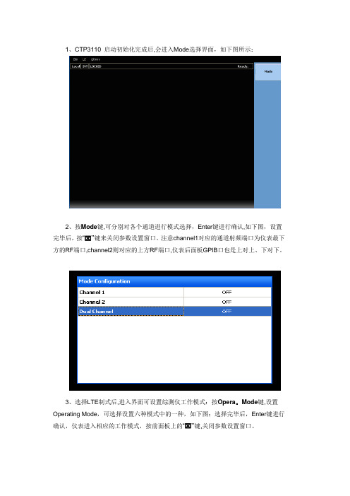
1、CTP3110 启动初始化完成后,会进入Mode选择界面,如下图所示:2、按Mode键,可分别对各个通道进行模式选择,Enter键进行确认,如下图,设置完毕后,按“⌧”键来关闭参数设置窗口。
注意channel1对应的通道射频端口为仪表最下方的RF端口,channel2则对应的上方RF端口,仪表后面板GPIB口也是上对上、下对下。
3、选择LTE制式后,进入界面可设置综测仪工作模式:按Opera。
Mode键,设置Operating Mode,可选择设置六种模式中的一种,如下图;选择完毕后,Enter键进行确认,仪表进入相应的工作模式,按前面板上的“⌧”键,关闭参数设置窗口。
4、高通平台终端如在LTE下注册,需要设置仪表的完整性算法参数,在cell off下点击仪表面板的如下图标红按钮,可以激活仪表下方的功能键菜单5、通过按键page翻页,找到“Security"按键,点击后,弹出如下对话框,将下图中标红的两个参数由“EIA0"都改为“EIA1”即可6、在仪表右侧功能菜单栏通过对应按键设置小区的对应band、频点、小区、带宽等7、按Opera。
Mode键,设置为“Active cell”激活小区,连接终端后开始注册流程,待注册完成后,仪表界面下方会显示对应的终端支持的band、cat等级等信息,同时仪表右侧功能菜单中“Originate”按键也会由灰色变为蓝色可选,此时点击“Originate”按键可以进行呼叫.8、点击仪表右侧菜单或者面板上的“MEAS键”可以打开测量项菜单,选择对应的测量项进行RF指标测量。
测量项测试操作可以参考“CTP3110_LTE使用手册。
pdf”9、如果选择TDSCDMA模式需要连接高通平台终端进行注册呼叫等测试的话,也需要设置完整性算法参数,方法与LTE类似,也是在cell off模式下在仪表下方功能菜单中找到“Security”按键,点击后,弹出如下对话框,将“Authentication Switch”设置为“on”即可。
- 1、下载文档前请自行甄别文档内容的完整性,平台不提供额外的编辑、内容补充、找答案等附加服务。
- 2、"仅部分预览"的文档,不可在线预览部分如存在完整性等问题,可反馈申请退款(可完整预览的文档不适用该条件!)。
- 3、如文档侵犯您的权益,请联系客服反馈,我们会尽快为您处理(人工客服工作时间:9:00-18:30)。
epro MMS3110 Shaft Vibration Transmitter User Manual
双通道轴振动变送器用户手册
成都松源测控技术有限公司 Email:cdsongyuan@ Tel: (028)85215448、85215428 Fax: (028)85215428-84
☞ 用于测量和处理轴振动信号,测量输入为涡流传感器,内置前置器。
符合最通用标准,如:VDI2059和API670。
☞ 冗余24Vdc 电源供电。
☞ 内置自检功能。
☞ 内置微处理器 ☞ 0/4…20mA 电流输出 ☞ 限值检测
应用:
双通道轴振动变送器是 MMS3000变送器系列之一,用于监测轴振动。
应用领域包括各种类型的涡轮机械,大型和小型的汽轮机、风扇、鼓风机、压缩机、齿轮箱、离心机、泵、磨煤机及其它。
本系统既适合发电厂、炼油厂、化工厂的大型设备,结合现场总线和PLC 、主计算机和网络一起使用,也适合测点少的小型涡轮机械独立监测。
变送器的输入为epro 涡流传感器 PR6422/…,PR6423/…,PR6424/…,和PR6425/… 此变送器不具备防爆功能。
功能及原理:
MMS3110双通道轴振动变送器将两个独立的涡流传感器的输入转换成两个独立的与振幅成正比的输出或一个与两个输入信号的最大值成正比的输出,参照 API670标准 max (Sx pp ,Sy pp )或参照VDI2059:Smax.
内置“自检”电路,监测传感器和变送器电路故障,如果发现故障,逻辑“OK ”输出将改变状态,同时4-20mA 输出变为0mA 。
初始设置是通过拨动开关和旋钮开关来进行。
变送器的出厂设置为最常用的工作方式,工厂也可以按用户要求进行设置。
成都松源测控技术有限公司 Email:cdsongyuan@ Tel: (028)85215448、85215428 Fax: (028)85215428-84
技术数据:
传感器输入
两路独立的带lemo 接头的涡流传感器输入,传感器为epro 公司的 PR6422/…,PR6423/…,PR6424/…,和PR6425/…。
标准测量范围: 通过拨动开关选择。
传感器类型
量程
PR6422/… 0…25/50/62.5/125/250μm op PR6423/… 0…50/62.5/125/250/500μm op PR6424/… 0…100/125/250/500/1000μm op PR6425/…
0…100/125/250/500/1000μm op
频率范围:1/5Hz…250/1500Hz 线性误差:< 0.25%
温漂:零点:< 0.05%/K ;增益范围:< 0.01%/K
时漂:零点:< 0.05%/24小时;增益范围:< 0.01%/24小时 信号输出:
两路0/4…20mA 电流输出,每通道一路,与相应输入成正比。
或一路电流输出与max (Sx pp ,Sy pp )、Smax 成正比。
允许负载:500 Ω
有短路和开路保护,通过夹线端子连接电缆。
两路缓冲电压输出(2-10V ),每个通道一路,与输入动态信号成正比,用于测试,也可以用于分析和诊断目的;
一个“OK ”状态输出和两个限值输出。
供电电源:18…24…31.2V 直流;变送器电路通过一个DC/DC 转换器与供电电源电隔离。
电流消耗:约 100mA/24V 功率消耗:约2.5瓦
环境条件:(符合 IEC359,DIN43745) 外壳:抗腐蚀,铝制
保护等级:IP65 参照 DIN40050, IEC144 CE 认证
成都松源测控技术有限公司 Email:cdsongyuan@ Tel: (028)85215448、85215428 Fax: (028)85215428-84
抗电磁干扰:参照EN55011 和 EN50082-2 工作温度范围:-20…+80℃ 存储温度范围:-30…+90℃ 允许相对湿度:0…95%无凝结
允许振动和撞击:撞击:20g/2ms ;振动:60Hz 时5g 安装方向:电缆出口位置参照图1
外形尺寸:127.5mm ×125.75mm ×80mm(宽×高×厚) 净重:约1300克 毛重:约1500克
附件:与变送器一起提供操作手册
模块 / 传感器监测:
内部的模块监测电路可以不间断地监测下列情况:
• 传感器信号在预置范围内;
• 传感器与模块之间的连接电缆“OK”(没有短路或开路) • 系统供电电压在预置范围内;
• 模块/传感器的状态通过光耦输出,其最大负荷为:
U = 48V DC ;I = 100mA
限值检测:
双通道时,通道1的特征值由黄色报警灯监视,通道2的特征值由红色报警灯监视。
单通道模式时,限值可以设定,如黄灯代表报警,红灯代表危险。
限值调整范围:0…100%满量程 光耦输出:Umax=48Vdc ;Imax=100mA
成都松源测控技术有限公司
Email:cdsongyuan@ Tel: (028)85215448、85215428 Fax: (028)85215428-84
成都松源测控技术有限公司
Email:cdsongyuan@ Tel: (028)85215448、85215428 Fax: (028)85215428-84
成都松源测控技术有限公司
Email:cdsongyuan@ Tel: (028)85215448、85215428 Fax: (028)85215428-84
图3 – MMS3110可调整器件分布示意图:。
