巨豪ZEBEX A-50M一维扫描模组
AXIS T91B50 高流量吸头爬虫机器人说明书
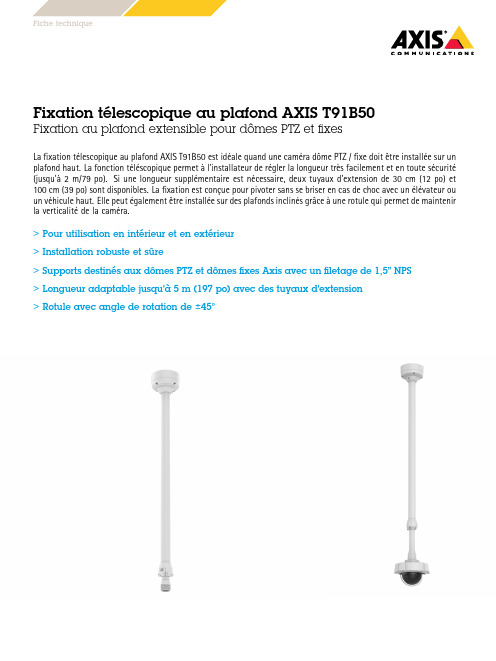
Fixation télescopique au plafond AXIS T91B50Fixation au plafond extensible pour dômes PTZ et fixesLa fixation télescopique au plafond AXIS T91B50est idéale quand une caméra dôme PTZ/fixe doitêtre installée sur un plafond fonction téléscopique permetàl'installateur de régler la longueur très facilement et en toute sécurité(jusqu'à2m/79po).Si une longueur supplémentaire est nécessaire,deux tuyaux d'extension de30cm(12po)et 100cm(39po)sont fixation est conçue pour pivoter sans se briser en cas de choc avec unélévateur ou un véhicule haut.Elle peutégalementêtre installée sur des plafonds inclinés grâceàune rotule qui permet de maintenir la verticalitéde la caméra.>Pour utilisation en intérieur et en extérieur>Installation robuste et sûre>Supports destinés aux dômes PTZ et dômes fixes Axis avec un filetage de1,5”NPS>Longueur adaptable jusqu'à5m(197po)avec des tuyaux d'extension>Rotule avec angle de rotation de±45°FichetechniqueFixation télescopique au plafond AXIS T91B50 GénéralProduits pris en charge Séries AXIS P55/P56/Q60/Q61(kit de suspension AXIS T94A01D nécessaire)Série AXIS M50(support de caméra1,5"NPS AXIS T91A05nécessaire)Série AXIS P33(kit de suspension AXIS P33nécessaire)Série AXIS P32/Q35(kit de suspension AXIS T94K01D/T94M01D nécessaire)AXIS M3004-V/M3005-V(kit de suspension AXIS T94B01Dnécessaire)AXIS M3006-V/M3007-P/M3007-PV(Kit de suspension AXIST94F01D nécessaire)AXIS M3024-LVE/M3025-VE/M3026-VE/M3027-PVE/M3037-PVE (kit de suspension AXIS T94F02D nécessaire)AXIS P3707-PE(kit de suspension AXIS T94M02D nécessaire) AXIS Q3709-PVE(kit de suspension AXIS T94A01D nécessaire) Caméras fixes Axis(support de caméra1,5"NPS AXIS T91A05nécessaire)Boîtier Aluminium chromatélaquéconforme aux normes NEMA4X* et IK10*Protection contre la corrosionEnvironnement IntérieurExtérieurCharge maximale10kg(22lb)Angle de rotation±45°Pose de câbles Côté:trou pour conduit de câble3/4”Arrière:trou pour conduit de câble3/4”Homologations IEC/EN/UL60950-1IEC/EN/UL60950-22EN50581IEC/EN62262IK10NEMA250Type4X**Protection contre la corrosion Dimensions Longueur minimale:1151mm(45po)Longueur maximale:2136mm(84po) Poids4,1kg(9lb)AccessoiresfournisGuide d’installationAccessoires enoptionTuyau d'extension30cm(12po)AXIS T91B52AXIS T91B52Extension Pipe100cm(40po)Pour plus d'accessoires,voir Garantie Garantie de3ans,voir /warranty Responsabilitéenvironnementale:/environmental-responsibility©2016-2020Axis Communications AB.AXIS COMMUNICATIONS,AXIS et VAPIX sont des marques déposées d’Axis AB ou encours de dépôt par Axis AB dans différentes juridictions.Tous les autres noms,produits ou services sont la propriétéde leursdétenteurs respectifs.Document sujetàmodification sans préavis.T10071340/FR/M3.2/2010。
巨普激光扫描枪(Z-3051HS)说明书

*数据加回车靠左
数据后加回车
数据靠左
数据后不加信息
数据后加空格
标有*的为系统默认设定
结束设定
开始设定
任何设定,首先扫描“开始 设定”,最后扫描“结束设定”
条码标识符设定为开放 后,会在显示条码数据前自 动加载一个标识符号。
根据标识符号,对照右表 即可判断条码的码制属性。
Code 39
M
ITF 2 of 5
Full ASCII ---X
Z-3051HS 扫描枪状态显示及故障排除
1.LED指示灯
扫描枪的顶部有三种指示灯颜色(蓝色、红色和绿色),这 三种指示灯颜色可以反映扫描枪的各种状态信息。
Full ASCII ---Y Full ASCII ---回车
Full ASCII ---Z Full ASCII ---空格
检查电源是 否正确连接 需送修
需送修
开始设定
任何设定,首先扫描“开始 设定”,最后扫描“结束设定”
ASCII Table
Full ASCII ---G Full ASCII ---I Full ASCII ---K Full ASCII ---M Full ASCII ---O Full ASCII ---Q
亲爱的用户: 您好!非常感谢您使用 ZEBEX 的产品。本公司
为专业条码扫描器生产厂家,多年来致力 AUTO-ID 领域的开发与研究,不断推出优良产品给客户使用。 希望 ZEBEX 高性能激光扫描枪能给您带来便利及 好的效益。
若您有什么问题可致电 021-64955599-351 或 传真到 021-64959598 与我们联系,我们将竭诚为 您服务!
可以解码但无法 传送至主机
解码时,LED灯 不亮 有激光发出但不 能读取任何条码 有开机声,无扫 描线
Eaton Enhanced 50系列光电传感器产品说明书
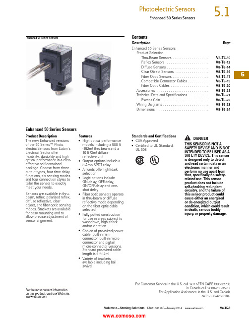
Volume 8—Sensing Solutions CA08100010E—January V8-T5-95For Customer Service in the U.S. call 1-877-ETN CARE (386-2273),in Canada call 1-800-268-3578.For Application Assistance in the U.S. and Canadacall 1-800-426-9184.Enhanced 50 Series SensorsEnhanced 50 Series SensorsContentsDescriptionPageEnhanced 50 Series Sensors Product SelectionThru-Beam Sensors . . . . . . . . . . . . . . . . . . .V8-T5-10Reflex Sensors . . . . . . . . . . . . . . . . . . . . . .V8-T5-12Diffuse Sensors . . . . . . . . . . . . . . . . . . . . . .V8-T5-14Clear Object Sensors . . . . . . . . . . . . . . . . .V8-T5-16Fiber Optic Sensors . . . . . . . . . . . . . . . . . . .V8-T5-17Compatible Connector Cables . . . . . . . . . . .V8-T5-19Fiber Optic Cables . . . . . . . . . . . . . . . . . . . .V8-T5-20Accessories . . . . . . . . . . . . . . . . . . . . . . . . . . .V8-T5-21Technical Data and Specifications . . . . . . . . . .V8-T5-21Excess Gain . . . . . . . . . . . . . . . . . . . . . . . . .V8-T5-22Wiring Diagrams . . . . . . . . . . . . . . . . . . . . . . . .V8-T5-23Dimensions . . . . . . . . . . . . . . . . . . . . . . . . . . .V8-T5-24Enhanced 50 Series SensorsProduct DescriptionThe new Enhanced versions of the 50 Series™ Photo-electric Sensors from Eaton’s Electrical Sector offerflexibility, durability and high optical performance in a cost-effective self-containedpackage. Choose from three output types, four time delay functions, six sensing modes and four connection styles to tailor the sensor to exactly meet your needs.Sensors are available in thru-beam, reflex, polarized reflex, diffuse reflective, clearobject, and fiber optic sensing modes. Brackets are available for easy mounting and to allow precise adjustment of sensor alignment.Features●High optical performance models including a 500 ft (152m) thru-beam and a 10ft (3m) diffuse reflective unit●Output options include a 3Amp SPDT relay●All units offer light/dark selection●Logic options include ON-delay, OFF -delay, ON/OFF -delay and one-shot delay●Fiber optic sensors operate in thru-beam or diffuse reflective mode depending on the fiber optic cable selected●Fully potted construction for use in areas subject to washdown, high shock and/or vibration●Choice of pre-wired power cable, built-in mini-connector, built-in micro-connector and pigtailmicro-connector versions. Standard pre-wired cable length is 6 ft (2m) ●Variety of brackets available including ball swivelStandards and Certifications●CSA Approved●Certified to UL Standard, UL 508DANGERTHIS SENSOR IS NOT ASAFETY DEVICE AND IS NOT INTENDED TO BE USED AS A SAFETY DEVICE. This sensor is designed only to detect and read certain data in an electronic manner and perform no use apart from that, specifically no safety-related use. This sensor product does not include self-checking redundant circuitry, and the failure of this sensor product could cause either an energized or de-energized outputcondition, which could result in death, serious bodily injury, or property damage.For the most current information on this product, visit our Web site:5Product Selection GuideConnection OptionsCable VersionProduct SelectionMini QD (Body)Micro or Euro (Micro)QD(Body)Micro or Euro (Micro)QD(Pigtail)Thru-Beam SensorsThru-Beam Standard Range 12NotesPage V8-T5-19.1 For a complete system, order one sensor and one detector.2 For brackets compatible with these sensors, see Accessories on Page V8-T5-21.VoltageRangeSensingRangeOptimumRangeSensingBeamThru-BeamComponent Output TypeTimeDelayConnectionType CatalogNumber 10–40 Vdc200 ft(61m)0.1 to 100 ft(0.03 to 31m)Infrared Source N/A N/A 6 ft cable1150E-6517Detector NPN/PNP 250 mA no1250E-6517yes1250E-8517Detector NPN/PNP 250 mA noDetector NPN/PNP 250 mA noyes12–240 Vdc24–240 Vac200 ft(61m)0.1 to 100 ft(0.03 to 31m)Infrared Source N/A N/A 6 ft cable1150E-6513Detector Isolated outputsolid-state relay300 mA at 240 Vac/dcno1250E-6513yes1250E-8513SPDT EM relay3A at 120 Vacno1250E-6514yes1250E-8514Detector Isolated outputsolid-state relay300 mA at 240 Vac/dcnoyesDetector Isolated outputsolid-state relay300 mA at 240 Vac/dcnoyesField of View: 2.4°V8-T5-10Volume 8—Sensing Solutions CA08100010E—January Volume 8—Sensing Solutions CA08100010E—January V8-T5-115Enhanced 50 Series SensorsThru-Beam Extended Range 12NotesPage V8-T5-19.1 For a complete system, order one sensor and one detector.2 For brackets compatible with these sensors, see Accessories on Page V8-T5-21.Voltage Range Sensing Range Optimum Range Sensing Beam Thru-Beam Component Output Type Time Delay ConnectionType Catalog Number 10–40 Vdc500 ft (152m)0.1 to 250 ft (0.03 to 77m)InfraredSource N/AN/A 6 ft cable1151E-6517DetectorNPN/PNP 250 mAno 1251E-6517DetectorNPN/PNP 250 mAno 24–240 Vac(152m)(0.03 to 77m)DetectorIsolated output solid-state relay300 mA at 240 Vac/dc no 1251E-6513yes 1251E-8513SPDT EM relay 3A at 120 Vacno 1251E-6514yes 1251E-8514DetectorIsolated output solid-state relay300 mA at 240 Vac/dc no yes DetectorIsolated output solid-state relay300 mA at 240 Vac/dc no yes DetectorIsolated output solid-state relay300 mA at 240 Vac/dc no yes Field of View: 2.4°5Reflex SensorsStandard Reflex 12NotesPage V8-T5-19.1 For a complete system, order one sensor and one retroreflector (see Tab 8, section 8.1).2 For brackets compatible with these sensors, see Accessories on Page V8-T5-21.3 Ranges based on 3 in retroreflector for reflex sensors.VoltageRangeSensingRange 3OptimumRange 3SensingBeam Output TypeTimeDelayConnectionType CatalogNumber 10–40 Vdc30 ft (9m)0.5 to 15 ft(0.2 to 4.6m)Visible red NPN/PNP 250 mA no 6 ft cable1450E-6517yes1450E-8517yes24–240 Vac(0.2 to 4.6m)solid-state relay300 mA at 240 Vac/dc yes1450E-85133A at 120 Vacyes1450E-8514Field of View: 1.0°V8-T5-12Volume 8—Sensing Solutions CA08100010E—January Volume 8—Sensing Solutions CA08100010E—January V8-T5-135Enhanced 50 Series SensorsPolarized Reflex 123NotesPage V8-T5-19.1 For a complete system, order one sensor and one retroreflector (see Tab 8, section 8.1).2 Polarized sensors may not operate with reflective tape. Test tape selection before installation.3 For brackets compatible with these sensors, see Accessories on Page V8-T5-21.4 Ranges based on 3 in retroreflector for reflex sensors.Voltage Range Sensing Range 4Optimum Range 4Sensing Beam Output Type Time Delay ConnectionType Catalog Number 10–40 Vdc16 ft (4.9m)0.5 to 8 ft (0.2 to 2.5m)Visible redNPN/PNP 250 mAno 6 ft cable1451E-6517yes 1451E-851712–240 Vdc 24–240 Vac16 ft (4.9m)0.5 to 8 ft (0.2 to 2.5m)Visible redIsolated output solid-state relay300 mA at 240 Vac/dcno 6 ft cable 1451E-6513yes 1451E-8513SPDT EM relay 3A at 120 Vacno 6 ft cable 1451E-6514yes 1451E-8514Field of View: 1.0°5Diffuse SensorsDiffuse Reflective 1NotesPage V8-T5-19.1 For brackets compatible with these sensors, see Accessories on Page V8-T5-21.2 Ranges based on 90% reflectance white card for diffuse reflective sensors.VoltageRangeSensingRange 2OptimumRange 2SensingBeam Output TypeTimeDelayConnectionType CatalogNumber 10–40 Vdc 5 ft (1.5m) 1 to 30 in(25 to 760 mm)Infrared NPN/PNP 250 mA no 6 ft cable1350E-6517yes1350E-8517yes24–240 Vac(25 to 760 mm)solid-state relay300 mA at 240 Vac/dc yes1350E-85133A at 120 Vacyes1350E-8514Field of View: 2.8°V8-T5-14Volume 8—Sensing Solutions CA08100010E—January Volume 8—Sensing Solutions CA08100010E—January V8-T5-155Enhanced 50 Series SensorsDiffuse Reflective Extended Range 1NotesPage V8-T5-19.1 For brackets compatible with these sensors, see Accessories on Page V8-T5-21.2 Ranges based on 90% reflectance white card for diffuse reflective sensors.Voltage Range Sensing Range 2Optimum Range 2Sensing Beam Output Type Time Delay ConnectionType Catalog Number 10–40 Vdc10 ft (3m)1 to 60 in(25 to 1520 mm)InfraredNPN/PNP 250 mAno 6 ft cable1351E-6517yes 1351E-851712–240 Vdc 24–240 Vac10 ft (3m)1 to 60 in(25 to 1520 mm)InfraredIsolated output solid-state relay300 mA at 240 Vac/dcno 6 ft cable 1351E-6513yes 1351E-8513SPDT EM relay 3A at 120 Vacno 6 ft cable 1351E-6514yes 1351E-8514Field of View: 2.8°5Clear Object SensorsClear Object Detector 12NotesPages V8-T5-19 and V8-T5-20.1 For a complete system, order one sensor and one retroreflector (see Tab 8, section 8.1).2 For brackets compatible with these sensors, see Accessories on Page V8-T5-21.VoltageRangeSensingRangeOptimumRangeSensingBeam Output TypeTimeDelayConnectionType CatalogNumber 10–40 Vdc45 in (1.2m) 1 to 24 in(25 to 610 mm)Visible red NPN/PNP 250 mA no 6 ft cable1452E-6517yes1452E-8517yes24–240 Vac(25 to 610 mm)solid-state relay300 mA at 240 Vac/dc yes1452E-85133A at 120 Vacyes1452E-8514Field of View: 0.68°V8-T5-16Volume 8—Sensing Solutions CA08100010E—January Volume 8—Sensing Solutions CA08100010E—January V8-T5-175Enhanced 50 Series SensorsFiber Optic SensorsFiber Optic Infrared 1NotesPages V8-T5-19 and V8-T5-20.1 For brackets compatible with these sensors, see Accessories on Page V8-T5-21.2 Field of view depends on fiber selected.3 For a complete system, order one sensor and one fiber optic cable (see Pages V8-T5-19 and V8-T5-20).4 Infrared fiber optic sensors are compatible with glass fiber optic cables (E51KE_).5 Diffuse mode—up to6 in (152 mm); thru-beam—up to 35 in (890 mm).Voltage Range Sensing RangeOptimum RangeSensing BeamOutput Type Time Delay ConnectionType Catalog Number 10–40 VdcDepends on fiber selected 5Depends on fiber selectedInfrared NPN/PNP 250 mAno 6 ft cable1550E-651712–240 Vdc 24–240 VacDepends on fiber selected 5Depends on fiber selectedInfrared Isolated outputsolid-state relay300 mA at 240 Vac/dcno 6 ft cable1550E-6513yes 3A at 120 Vacyes 1550E-8514Field of View: 234V8-T5-18Volume 8—Sensing Solutions CA08100010E—January 5Fiber Optic Visible 1NotesPage V8-T5-19.1 For brackets compatible with these sensors, see Accessories on Page V8-T5-21.2 Field of view depends on fiber selected.3 For a complete system, order one sensor and one fiber optic cable (see Page V8-T5-20).4 Visible fiber optic sensors are compatible with plastic fiber optic cables only.5 Diffuse mode—up to 3 in (76 mm); thru-beam—up to 35 in (890 mm).Voltage Range Sensing RangeOptimum RangeSensing BeamOutput Type Time Delay ConnectionType Catalog Number 10–40 VdcDepends on fiber selected 5Depends on fiber selected InfraredNPN/PNP 250 mAno 6 ft cable1551E-6517yes 1551E-851724–240 Vacselected 5selected solid-state relay300 mA at 240 Vac/dcyes 1551E-8513yes 3A at 120 Vacyes 1551E-8514Field of View: 2345Enhanced 50 Series SensorsCompatible Connector CablesStandard Cables—Micro1Standard Cables—Mini1Note1 For a full selection of connector cables, see Tab 10, section 10.1.Voltage StyleNumber of PinsGauge LengthPin Configuration/Wire Colors(Face View Female Shown)PVC Jacket Catalog Number PUR Jacket Catalog NumberIRR PUR Jacket Catalog NumberMicro-Style, Straight Female AC Micro4-pin,4-wire22 AWG6 ft (2m)CSAS4F4CY 2202 CSAS4F4RY 2202CSAS4F4IO 22025-pin,5-wire22 AWG 6 ft (2m)CSAS5A5CY2202——DC4-pin,4-wire22 AWG 6 ft (2m)CSDS4A4CY 2202 CSDS4A4RY 2202CSDS4A4IO 2202Current Rating at 600VVoltage StyleNumber of PinsGaugeLengthPin Configuration/Wire Colors(Face View Female Shown)Catalog NumberMini-Style, Straight Female 8AAC/DC4-pin,4-wire16 AWG6 ft (2m)CSMS4A4CY16025-pin, 5-wire16 AWG 6 ft (2m)CSMS5A5CY1602Micro-Style, Straight FemaleMini-Style,Straight Female5Fiber Optic CablesGlass Fiber Optic CablesGlass Fiber Optic Cables—Duplex Cables(for Diffuse Reflective Sensing)Glass Fiber Optic Cables—Single Cables(for Thru-Beam Sensing)Plastic Fiber Optic CablesPlastic Fiber Optic Cables—Pre-Assembled Duplex CablesPlastic Fiber Optic Cables—Pre-Assembled Single CablesNotes1 Larger diameter (1.5 mm) fibers provide approximately 50% longer sensing range than small diameter (1 mm).2 One cable.3 Set of two.Fiber BundleSize Ain In (mm)Stainless SteelJacketCatalog NumberPVC/MonocoilJacketCatalog NumberForward Viewing, Unthreaded0.125 (3.2)E51KE713E51KE313Right Angle Viewing, Unthreaded0.125 (3.2)E51KE733E51KE333Forward Viewing, Threaded Cable End0.125 (3.2)E51KE723E51KE323Right Angle Viewing, Threaded Cable Shaft0.125 (3.2)E51KE7A3E51KE3A3Right Angle Viewing, Threaded Cable End0.125 (3.2)E51KE7B3E51KE3B3Dimensions, see Page V8-T5-25.Sensing Tip StyleForward Viewing,UnthreadedRight Angle Viewing,UnthreadedForward Viewing,Threaded Cable EndRight Angle Viewing,Threaded Cable ShaftRight Angle Viewing,Threaded Cable EndFiber BundleSize Ain In (mm)Stainless SteelJacketCatalog NumberPVC/MonocoilJacketCatalog NumberForward Viewing, Unthreaded0.125 (3.2)E51KE813E51KE413Right Angle Viewing, Unthreaded0.125 (3.2)E51KE833E51KE433Forward Viewing, Threaded Cable End0.125 (3.2)E51KE823E51KE423Right Angle Viewing, Threaded Cable Shaft0.125 (3.2)E51KE8A3E51KE4A3Right Angle Viewing, Threaded Cable End0.125 (3.2)E51KE8B3E51KE4B3Dimensions, see Page V8-T5-25.Sensing Tip StyleForward Viewing,UnthreadedRight Angle Viewing,UnthreadedForward Viewing,Threaded Cable EndRight Angle Viewing,Threaded Cable ShaftRight Angle Viewing,Threaded Cable EndFiber Diameterin In (mm) Catalog NumberLarge Diameter, Threaded Tip0.059 (1.5)6324E-6501 12Large Diameter, Threaded Tip with Bendable Probe0.039 (1.0)6324E-6502 2Dimensions, see Page V8-T5-25.Sensing Tip StyleLarge Diameter,Threaded TipLarge Diameter,Threaded Tip withBendable ProbeFiber Diameterin In (mm) Catalog NumberLarge Diameter, Threaded Tip0.059 (1.5)6323E-6501 13Large Diameter, Threaded Tip with Bendable Probe0.039 (1.0)6323E-6502 3Dimensions, see Page V8-T5-25.Sensing Tip StyleLarge Diameter,Threaded TipLarge Diameter,Threaded Tip withBendable Probe5Enhanced 50 Series SensorsAccessoriesEnhanced 50 Series SensorsTechnical Data and SpecificationsEnhanced 50 Series SensorsDescriptionCatalog NumberMounting Bracket Right Angle—ShortProvides for full 360° rotation of sensor.Bracket slots allow for up to 1.5 in of vertical adjustment. Nickel plated6150E-6501Mounting Bracket Right Angle—T allProvides for full 360° rotation of sensor.Bracket slots allow for up to 1.5 in of vertical adjustment in each slot, and 3.5 in of overall positioning adjustment.6150E-6502Mounting Bracket Right Angle—Ball SwivelProvides for full 360° rotation of sensor. Ball swivel allows for ±30° sensor angle.6150E-6503RetroreflectorsRetroreflectors and retroreflective tape, see Tab 8, section 8.1—Connector CablesFor use with connector version sensors, see Tab 10, section 10.1—Dimensions , see Page V8-T5-25.Description AC/DCEM Relay ModelSpecification AC/DCSolid-state Relay Model Specification DC OnlyStandard Range Model Specification DC OnlyExtended Range Model Specification Input voltage 12–240 Vdc; 24–240 Vac 12–240 Vdc; 24–240 Vac 10–40 Vdc 10–40 Vdc Light/dark operation Switch selectableSwitch selectableSwitch selectableSwitch selectableOperating temperature –13° to 131°F (–25° to 55°C)–13° to 131°F (–25° to 55°C)–13° to 131°F (–25° to 55°C)–13° to 131°F (–25° to 55°C)Humidity 95% Relative humidity, non-condensing 95% Relative humidity, non-condensing 95% Relative humidity, non-condensing 95% Relative humidity, non-condensing Case material Fiberglass reinforced plastic Fiberglass reinforced plastic Fiberglass reinforced plastic Fiberglass reinforced plastic Lens material AcrylicAcrylicAcrylicAcrylicVibration IEC 60947-5-2 part 7.4.2IEC 60947-5-2 part 7.4.2IEC 60947-5-2 part 7.4.2IEC 60947-5-2 part 7.4.2Shock IEC 60947-5-2 part 7.4.1IEC 60947-5-2 part 7.4.1IEC 60947-5-2 part 7.4.1IEC 60947-5-2 part 7.4.1ProtectionOutput short circuit and overcurrent protection Reverse polarity protection Output short circuit and overcurrent protection Reverse polarity protection Output short circuit and overcurrent protection Reverse polarity protection Output short circuit and overcurrent protection Reverse polarity protection Enclosure ratings IP67, IP69KIP67, IP69K IP67, IP69K IP67, IP69K Output load 3A at 120 Vac; 3A at 240 Vac 3A at 28 Vac 300 mA at 240 Vac/dc 250 mA at 40 Vdc 250 mA at 40 Vdc Response time 15 ms 2 ms 2 ms 2 ms Timer timing response 0–15 sec.0–15 sec.0–15 sec.0–15 sec.No load current <30 mA <30 mA <30 mA <30 mA Leakage current (max.)—1 mA at 240 Vac<10 μA<10 μAIndicator LEDs Green: output; yellow: power; red: alignmentGreen: output; yellow: power; red: alignment Green: output; yellow: power; red: alignment Green: output; yellow: power; red: alignment Emitter LEDDiffuse, infrared fiber optic, thru-beam modelsInfrared 880 mm Infrared 880 mm Infrared 880 mm Infrared 880 mm Reflex, polarized reflex, clear object, visible fiber optic unitsVisible red 660 mm Visible red 660 mmVisible red 660 mmVisible red 660 mmMounting Bracket Right Angle—ShortMounting Bracket Right Angle—TallMounting Bracket Right Angle—Ball Swivel5Excess GainThru-BeamThru-beam1. 1151E/1251E2. 1150E/1250EDiffuse ReflectiveDiffuse reflective90% reflectance white card1. 1351E2. 1350EReflexReflex3 in retroreflector1. 1450E2. 1451EClear Object DetectorClear object detector3 in retroreflector1. 1452EFiber Optic DiffuseFiber optic diffuse0.125 in dia. glass fiber0.040 in dia. plastic fiber1. 1550E2. 1551EFiber Optic Thru-BeamFiber optic thru-beam0.125 in dia. glass fiber0.040 in dia. plastic fiber1. 1550E2. 1551E5Enhanced 50 Series SensorsWiring DiagramsPin numbers are for reference, rely on pin location when wiring. Enhanced 50 Series SensorsNotes1Connecting the test input to 0 Vdc allows you to switch the light source off for troubleshooting while leaving the sensor under power. 2Over current protection is to be provided in the field. Conductor size for 20 AWG: 5 amp; 22 AWG: 3 amp; 24 AWG: 2 amp.3Connect load to appropriate output for either sinking or sourcing operation.Operating VoltageCable ModelMini-Connector Model (Face View Male Shown)Micro-Connector Model (Face View Male Shown)Thru-Beam Source 10–40 VdcAll Others 10–40 VdcThru-Beam Source 12–240 Vdc or 24–240 Vac solid-state relay 2All Others with Isolated AC/DC Output 12–240 Vdc or 24–240 Vac solid-state relay 2Thru-Beam Source 12–240 Vdc or 24–240 Vac SPDT EM relay 2All Others12–240 Vdc or 24–240 Vac SPDT EM relay235DimensionsApproximate Dimensions in Inches (mm)Enhanced 50 Series SensorsCable and Pigtail Connector VersionsClear Object VersionsMini-Connector VersionsAC/DC Micro or Euro (Micro) Connector VersionsTop ViewsWith Timing Without Timing5Enhanced 50 Series SensorsApproximate Dimensions in Inches (mm)Glass Fiber Optic Cables—Duplex Cables Stainless Steel Jacket shown for all.Collar Mounting EndForward Viewing, UnthreadedRight Angle Viewing, UnthreadedForward Viewing, Threaded Cable EndRight Angle Viewing, Threaded Cable ShaftRight Angle Viewing, Threaded Cable EndGlass Fiber Optic Cables—Single Cables Stainless Steel Jacket shown for all.Collar Mounting EndForward Viewing, UnthreadedRight Angle Viewing, UnthreadedForward Viewing, Threaded Cable EndRight Angle Viewing, Threaded Cable ShaftRight Angle Viewing, Threaded Cable End5Approximate Dimensions in Inches (mm)Plastic Fiber Optic Cables—Pre-Assembled Duplex CablesLarge Diameter, Threaded TipLarge Diameter, Threaded Tip with Bendable ProbePlastic Fiber Optic Cables—Pre-Assembled Single CablesLarge Diameter, Threaded TipLarge Diameter, Threaded Tip with Bendable ProbeAccessoriesMounting Bracket Right Angle—ShortMounting Bracket Right Angle—T allMounting Bracket Right Angle—Ball Swivel。
强力巨彩P4模组Q4E16V8.5(8个铜螺母)规格书

产品规格书SPECIFICATION产品名称:室内P4十六扫全彩表贴三合一单元板规格型号:Q4E16V8.5文件编号:版本编号: 1.0目录目录 (1)1.适用范围 (2)2.产品说明 (2)3. 产品介绍 (3)4. 信号引脚定义 (4)5. 规格型号说明 (4)6. 线路原理图 (4)7. IC贴片图 (5)8. 安装孔位图 (5)9. 安装指导方式 (10)10. 软件安装 (12)11. 开关电源配置参数 (13)12. 产品使用注意事项 (13)13. 单元板备件 (16)1. 适用范围本技术手册仅适用于室内Q4E16V8.5(64*32)十六扫全彩表贴三合一单元板。
2. 产品说明2.1. 室内P4.0十六扫全彩表贴三合一单元板主要是由红色LED晶片、绿色LED晶片和蓝色LED晶片封装为一个像素点后组成矩阵,再固定到塑胶套件上而成;2.2. 此单元板含有驱动芯片和输入缓冲芯片,连接到LED显示屏控制系统即可显示视频、图像和文字信息等;2.3. 通过OE信号驱动红色LED、绿色LED和蓝色LED的驱动芯片,可形成43980亿种颜色变换;2.4. 此单元板可以按水平和垂直方向任意拼接,从而拼成不同大小的显示屏;2.5. 单元板的特点:●用超高亮的LED和优质的塑胶件●高对比度可达到良好的显示效果●重量轻易于安装、拆卸●可进行单点、单灯维护,成本低●采用恒流方式驱动LED,发光均匀,功耗低●像素间距为4.0mm,共有64*32个像素点,每个像素点由1R1G1B组成2.6. 单元板图片3.产品介绍3.1LED参数:3.2屏体技术参数:4.信号引脚定义HUB75C5.规格型号说明产品型号命名规范:6.线路原理图7.IC贴片图8.安装孔位图8.1单元板安装孔位:备注:“如有制作箱体,请提前告知办事处并确认订单产品孔位图”所有尺寸的单位为mm。
8.4压铸箱实物图:正面视图背面视图正面侧视图背面侧视图8.5压铸箱实物说明图:镀铬提手9.安装指导方式9.1箱体屏安装简介:9.1.1安装方式(显示屏安装结构简易图)注:以上为目前显示屏安装中常用的六种安装方式,对于室内显示屏一般采A\B\C\D四种安装方式,户外显示屏以上方式均可采用。
巨豪条码扫描枪-产品介绍

巨豪ZEBEX Z-6170多线激光扫描平台
3. 大功率丽音设计, 适合各种嘈杂的环境 1. 32 bit MPU硬件解 码,读码更轻松、更 精准
2. 独特的球面收光技术, 使读码效率趋于完美
4、独创广角无极 调节底座,扫描角 度更大、更广
5、硅晶塑胶吸盘设计,使安 装固定更加方便
巨豪Z-6070双镭射全方位激光扫描平台
巨豪ZEBEX Z-6182嵌入式扫描平台
1、双镭射技术:采用双镭射扫 描技术,能同时产生32条扫描 线,可达每秒2400次的高速准 确扫描
2、高性能Z-SCAN硬件解码技术: ZEBEX自行研发的Z-SCAN芯片, 具有高性能的硬件解码技术,能 及时同步且IP54标准:可以达到 严苛的工业防尘防水标准
巨豪ZEBEX Z-6082立式激光平台
1)双镭射技术:采用双镭射扫描技术,能 同时产生32条扫描线,可达每秒2400次的 高速准确扫描 2)高性能Z-SCAN硬件解码技术:ZEBEX 自行研发的Z-SCAN芯片,具有高性能的硬 件解码技术,能及时同步且准确无误的解读 各种条码 3)严格执行IP54标准 4)形成耐用的环境抵抗罩 5)条码缝合功能 6)瞬间自动唤醒功能 7)时尚科技感蓝色LED 8)配置简单、便于升级 9)预留RFID
巨豪Z-5151高速单线激光扫描模组
唤 醒 功 能 自 动 休 眠
键盘口,RS-232, USB通讯接口
1、 高性能单线激光扫描引擎 扫描速度可达每秒500线
2、采用精巧外观设计, 铝制外壳更加坚固耐用.
3、IP54标准,达到严苛 的工业防尘防水标准。
扫描网是深圳市信华翰科技有限公 司打造的扫描枪的网上商城。信华 翰为了让中国的条码事业走得更好 更快,让大众都能享受条码带来的 便利,特此为全国商户带来质优价 廉的各类扫描枪,扫描网代理的所 有巨豪扫描枪均是厂家授权,均经 过“三测”(出厂检测,到货检测, 出货检测)的优良产品。
巨豪ZEBEX Z-6170激光扫描平台 便利店扫描枪
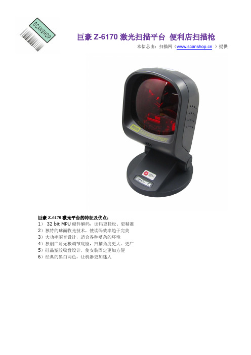
巨豪Z-6170激光扫描平台便利店扫描枪本信息由:扫描网()提供巨豪Z-6170激光平台的特征及优点:1) 32 bit MPU硬件解码,读码更轻松、更精准2)独特的球面收光技术,使读码效率趋于完美3)大功率丽音设计,适合各种嘈杂的环境4)独创广角无极调节底座,扫描角度更大、更广5)硅晶塑胶吸盘设计,使安装固定更加方便6)经典的黑白两色,让机器更加迷人巨豪Z-6170激光平台的外观尺寸图:巨豪Z-6170激光平台的如何恢复出厂设置?在某些特殊情况下,您可能需要将巨豪Z-6170激光平台恢复出厂设置,读取下面的条码可将Z-6170激光平台的各参数恢复至出厂默认值。
巨豪Z-6170激光平台的性能参数光源:650nm可见激光二极管景深:0-200mm(UPC/EAN 100%,PCS=90%)扫描角度:5个方向区域扫描扫描速度:1400线/秒扫描线数:20线分辨率:5 mil @ PCS=90%印刷对比度:30% @ UPC/EAN 100%LED指示:双色LED(蓝色和红色)声音:可调音量及音调电源参数输入电压:5 VDC±10%消耗功率:1.35瓦工作电流:270mA(典型); 350mA(峰值)安全标准镭射安全:CDRH Class IIa;IEC 60825-1:Class 1电磁兼容:CE En55022 B,FCC Part 15 Class B ,VCCI,BSMI 环境参数工作温度:0℃-40℃(32OF-104OF)储藏温度:-20℃-60℃(-4OF-140OF)工作湿度:5%-90%RH(无凝结)环境亮度:Up to 4,000 Lux(fluorescence)抗震能力:从1m高处跌落至水泥地面,仍可正常工作。
一维条码平台 (2)知识分享

1、 霍尼韦尔MS3580是一款性能卓越、设计紧 凑、全向多线和单线组合型激光条形码扫描器。
2、它适用于中小流量商业零售场合如便利店、酒 类专卖店和药店。
3、用户可以自行将霍尼韦尔MS3580扫描器的扫描 图案设置成平行线式和单线式,足手持式和固定式 扫描的双重需求。
4、QuantumT的整个机身被一个弹性橡胶体所包围 保护,能够承受日常频繁扫描所带来的摩擦碰撞, 牢固耐用。
2020/10/4
优解5800全向多线激光固定式条码扫描器
1、优解5800是一款性能卓越、设计紧凑、全向多线和单线组合 型激光条形码扫描仪。小巧多样的支座安装方式有效节省了柜台 空间,是便利店和各类专卖店的理想首选。
2、在出厂默认状态下, 优解5800每秒能产生1650条密集的激光 线,条码扫描一次通过率高,提高工作效率和客户满意度。
2、摩托罗拉Symbol ls9203扫描平台的体积小巧,可以 留出足够空间让您摆放“冲动性购买”的陈列品,以推动 额外销售。而且,借助Symbol ls9203扫描平台可更准 确地跟踪客户行为的功能,您可以改进库存管理情况, 并确保在客户需要产品时有现货提供给客户。
3、该扫描平台适用于药房及商店、图书馆、办公自动 化等。高性能、全方位扫描模式 ,提高新老用户的效 率,缩短收银等候时间,为顾客提供更好的服务。
2020/10/4
V50说明书
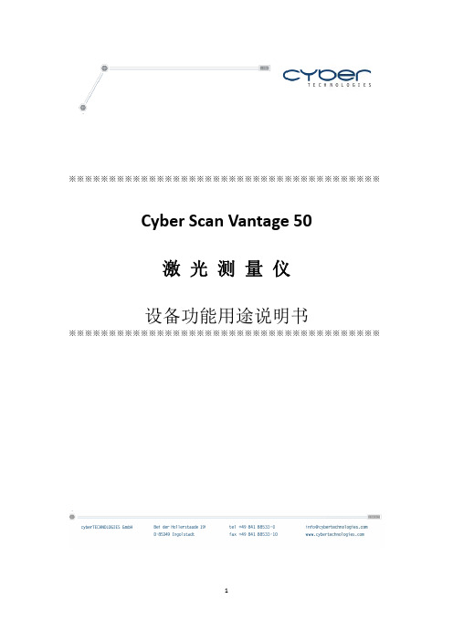
上图为 CyberScan Vantage 50 搭配 LT9010 型号激光光学传感器时设备图
6
4. 设备功能用途说明
CyberScan Vantage 50 激光非接触式二维或三维测量系统广泛在微电子和其他 精密工业中大量应用,CyberScan 的 Vantage 50 整合了激光光学技术和电脑控 制的工作平台移动技术,使 Vantage 50 在没有工装夹具的实际限制下,能达到 最大的弹性应用范围。对小的被测物体可以简单的直接放置于可移动传感器的下 面进行测量。CyberScan 的 Scan CT 应用软件提供了全面的广泛的二维/三维轮 廓测量,使 Vantage 50 可以测量高度、长度、宽度、面积、弧度、粗糙度、倾
在激光光学传感器聚焦的情况下设定起点位置(Start)、终点位置(End)和马达 扫描步距(Step),步距设定越小量测精度越高,步距设定越大则精度越差,故 需按实际量测物品情况设定合适的步距(建议 5um)。
3.以上量测起点和终点及量测步距都设定好了后,点击量测键
进行扫
描量测。设备会进行自动量测并产生所量测位置的二维剖面曲线图出来,此时我 们需点选 Analyse 分析功能菜单介面。
我们的非接触式三维测量系统广泛应用于微电子和其他精密工业中大量应 用,包括台阶高度测量、轮廓测量、粗糙度测量、平整度测量、太阳能电池的测 量等。我们的解决方案得到大型国际公司信任,以及许多中小型企业应用于研发 和生产。并在全球构建了完善的合格代理商或分销商网络。为我们的客户提供全 方位的技术运用支持。 cybertechnologies 是一个强大的全球高精度测量系统 设备制造商,值得全球客户信任。
Y 方向最大扫描长度 50 mm 基于 2um 步距时 Y 轴测量速度为 1 mm / sec Y 轴最小马达移动步距为 1um
巨豪条码扫描枪Z-3010 USB模式下关于后缀的数据处理

巨豪条码扫描枪Z-3010
USB模式下关于后缀的数据处理
文章来源:扫描网
条码扫描器的功能其实是有很多的,包括前缀和后缀,恢复出厂设置等等,其中最经常用到的设置就是后缀了,有些扫描器用户因为要方便工作数据更容易处理,需要对数据进行相关的后缀,下面我们以巨豪Zebex Z-3010红光扫描枪为例,来教大家一些最基础的扫描枪后缀数据的设置方法。
首先需要告诉大家关于扫描枪设置的通用步骤,大家需要依次扫描以下条码方可完成扫描枪的设置。
步骤1、开始设定
步骤2、需要设置的格式条码
步骤3、结束设定
(1)大家如果想在每次扫描后,数据后面出现一个回车,那么在设定的第二步时,你需要扫描数据后加回车这个条码,如图:
(2)如果可能之前已经设置了回车或其他设置,现在不想在数据后面添加信息了,怎么办呢?这时,你可以通过扫描“数据后不加信息”条码来完成设置。
(3)如果你想在每次扫描后数据后面出现一个TAB,那么你可以扫描一下“数据后加TAB”条码即可。
【扫描网网站免费提供国内外20多个知名品牌扫描枪的高清图和用户手册资料下载】。
ZEBEX Z-107x系列移动数据采集器 说明书

Z-107x系列移动数据采集器用户手册声明ZEBEX是巨豪实业股份有限公司的注册商标,本手册中提到的其余商标均属于相应公司所有。
本手册的内容可能会被更改或更新而不另行通知,本手册所提供的信息也可能不够准确,ZEBEX 公司对此不承担任何法律责任。
版权所有,未经ZEBEX公司授权不得转印、复制或出售本文档的任何内容,本手册最终解释权归ZEBEX公司所有。
版本号:2007-09目录介绍 (1)拆包 (2)外观及说明 (3)电池充电 (4)开机并扫描测试 (6)上传数据至PC机 (8)设置 (10)附录: 产品规格及特性 (12)首先感谢您选用ZEBEX公司这款带有显示屏的移动数据产品(PDC),此款产品非常小,方便携带,易于操作。
系统包括实时时钟、蜂鸣器、LED 指示灯,以及串口/USB口用来和外界设备通信。
Z-107x内建32K内存用来存储条码数据,可以保存超过1000条的记录。
该数据采集器出厂的时候已经自带了一个应用程序,可以用来扫描并存储条码,并且可以通过RS232或者USB线把采集到的数据上传到PC机。
在光碟里面,有一编程工具(WinTaskGen),它是基于Windows操作系统的应用程序,用户可以在此应用程序上开发自己的应用软体(Tasks),一个新的Task可以最多包括4个表,每个表可以最多包括16个字段。
如果需要更高要求的数据采集任务,用户可以使用我们提供的库函数在Keil C的环境下开发新的更高应用程序。
Z-107X应该包括以下一些部件:打开包装,如下图所示,确认以下物品:图1到图7分别为:袖珍型数据采集器Z-107X;RS232数据线;USB线(可选);3节可充式镍电池;一个电源充电器;一张光盘和一本用户手册。
如果有任意一件物品损坏或者不存在,请立刻联系经销商。
外观及说明电池充电为了提高产品的性能,Z-107X提供了高品质、可充电的镍电池,并且配有充电器;电池装好后,连接好数据线,将充电器插入数据线的DC JACK 口,电池就可以立即充电了,充电时LED指示红色。
EVOLVE 50M 便携式有源列阵系统 用户手册说明书

ElectroVoice | EVOLVE 50M Portable Powered Column System EVOLVE 50M Portable Powered Column System▪The EVOLVE 50M joins the EVOLVE 50 andEVOLVE 30M in the award-winning EVOLVEseries - globally recognized as the benchmarkfor performance in column systems▪Professional performance, column convenience - superior Electro-Voice-engineered componentsand premium materials deliver best-in-classsound quality, power and reliability▪No need to bring additional gear to the gig -onboard eight-channel digital mixer with pro-grade preamps and studio-quality effects▪Easily expand your PA - use QuickSmart Link to connect two EVOLVE 50Ms via a network cable- double your mic/line inputs and mix the wholeband via the QuickSmart Mobile appElectro-Voice is expanding its industry-leading EVOLVE series with the launch of the EVOLVE 50M column loudspeaker system. The EVOLVE 50M features Electro-Voice’s new QuickSmart Link digital audio and control technology, an onboard mixer, DSP and effects - all combined within the sleek EVOLVE 50 format. The EVOLVE 50M is the perfect choice for bands/musicians, AV rental companies, DJs and any application where true professional audio performance is required in a super-compact and portable package.Available in black or white finishes, the EVOLVE 50M combines state-of-the-art industrial design, superior Electro-Voice-engineered components and premium materials to deliver best-in-class sound quality, power and reliability. The full-range column array and its eight lightweight 3.5” neodymium drivers provide ultra-wide, full-bandwidth 120° coverage via proprietary waveguides; array-formed 40° asymmetrical vertical coverage ensures acoustic output is directed towards both sitting and standing audience members. The array enclosure is constructed from a durable composite material and incorporates an ergonomic aluminum handle. A 12” subwoofer is housed in a 15 mm wood enclosure with a high-efficiency laminar-flow vent design, for enhanced rigidity and acoustical performance. The array and sub are connected via a symmetrical aluminum pole with internal wiring and magnetically assisted latching. The speakers are protected by a black powder-coated 18-gauge steel grille, and an array/pole carry case is included. An advanced Class-D amplifier provides up to 1000 W of power.Equipped with the most comprehensive and user-friendly feature set of any column system on the market today, the EVOLVE 50M’s “M” designation refers to its integrated fully featured, fully configurable eight-channel digital mixer. Developed in collaboration with the world-class audio electronics engineering team at Electro-Voice’s sibling brand Dynacord, the mixer has multiple inputs (4x XLR/TRS combo mic/line inputs, 1x XLR/TRS combo stereo line input, 1x RCA, 1x 3.5 mm stereo, 1x Hi-Z instrument input) with professional-grade preamps and mix functions. High-resolution, low-latency Bluetooth® streaming ensures excellent results for music playback or accompaniment. Independent channel aux sends and a foot switch input are also included, and a range of effects (30 presets, including chorus, delay, flange and reverb, via two FX channels) add a myriad of options for musicians to fine-tune their tone. All of the above help to reduce load-in/out and setup/teardown time - and on-stage clutter - by minimizing the need for external equipment such as a mixer and effects pedals.New from Electro-Voice, QuickSmart Link makes it easy to combine two EVOLVE 50Ms for use together with larger bands or gigs needing more inputs. Simply link the systems together via an Ethernet cable to create an uncompressed digital audio/control connection, pair both systems to a single mobile device via the QuickSmart Mobile app (available via the Apple App Store and on Google Play), and get full mix control of both systems. For applications requiring fewer inputs, but still requiring a mixer and stereo output, the EVOLVE 50M can be matched with an EVOLVE 50 via the MIX OUT XLR connector.The EVOLVE 50M’s control panel features Electro-Voice’s powerful QuickSmart DSP, which allows the navigation and adjustment of all audio, effects and mix functions via an LCD with single-knob control or via the QuickSmart Mobile app, as well as multiple options for signal routing and inputs. Functions include four presets (Music, Live, Speech, Club), three-band system EQ (low, mid, high), seven-band graphic EQ (in Mixer mode), five user-programmable presets (Store and Recall settings), phantom power, visual monitoring of limiter status, input level control and meters, and a master volume control to optimize gain structure. Technical specifications2Maximum SPL is measured at 1 m using broadband pink noise at maximum output.3Current rating is 1/8 power.Frequency response:Dimensions:Ordering informationEVOLVE50-TB Column speaker array, pole, black EVOLVE 50 column array, sub pole, and carrying bag, black Order number EVOLVE50-TB | F.01U.335.090EVOLVE50M-SB-US Column speaker sub US, black EVOLVE 50M column subwoofer, US, blackOrder number EVOLVE50M-SB-US | F.01U.384.340 EVOLVE50M-SB-EU Column speaker sub EU, black EVOLVE 50M column subwoofer, EU, blackOrder number EVOLVE50M-SB-EU | F.01U.384.341 EVOLVE50-TW Column speaker array, pole, white EVOLVE 50 column array, sub pole, and carrying bag, whiteOrder number EVOLVE50-TW | F.01U.335.099EVOLVE50M-SW Column speaker sub, US & EU, white EVOLVE 50M column speaker sub, US & EU, whiteOrder number EVOLVE50M-SW | F.01U.384.342 AccessoriesEVOLVE50-SUBCVR Subwoofer coverCover for the EVOLVE 50 subwoofer, blackOrder number EVOLVE50-SUBCVR | F.01U.336.241EVOLVE50-CASE Column speaker carrying case, wheels Column speaker carrying case with wheels, blackOrder number EVOLVE50-CASE | F.01U.335.110 EVOLVE50-PL-SB Column speaker pole, short, black Column speaker short pole, blackOrder number EVOLVE50-PL-SB | F.01U.335.108 EVOLVE50-PL-SW Column speaker pole, short, white Column speaker short pole, whiteOrder number EVOLVE50-PL-SW | F.01U.335.109Represented by: Germany:Bosch Sicherheitssysteme GmbH Robert-Bosch-Ring 585630 GrasbrunnGermany Bosch Security Systems, LLC 12000 Portland Avenue South Burnsville MN 55337USA© Bosch Security Systems2021 | Data subject to change without notice 202101151153 | V1 | January 15, 2021。
厦门纵行信息科技有限公司 ZETA 低功耗广域物联网 (LPWAN) 测试套件 V2.9说明书

ZETA®低功耗广域物联网(LPWAN)测试套件手册V2.9版权说明本文件版权归厦门纵行信息科技有限公司所有,事先未获得厦门纵行信息科技有限公司公司书面允许,不得以任何方式进行复制。
免责声明厦门纵行信息科技有限公司对本产品如有更改,恕不另行通知。
由厦门纵行信息科技有限公司提供的信息准确可靠。
但我公司对其使用,以及因使用它而侵犯专利或第三方的权利不承担责任。
其它未通过专利许可认证的,即被视为厦门纵行信息科技有限公司的专利所有权内。
目录1.套件清单 (4)2.设备使用 (6)2.1基站使用 (6)2.2中继使用 (7)2.3终端使用 (8)2.4使用流程 (9)3.web管理使用 (9)3.1注册 (9)3.2登入 (9)3.3管理设备 (10)3.3.1基站管理 (10)3.3.2中继管理 (11)3.3.3终端管理 (11)1.套件清单测试套件总共包含两个盒子,包含:设备:1个基站+1个中继+1个带底板终端+1个邮票版终端设备功能概述基站管理ZETA 设备回传数据至Internet中继补充覆盖,数据分流带底板终端快速搭建测试环境邮票版终端产品开发配件:1根1.2m/40cm 玻璃钢天线(基站使用,日本市场使用40cm)+1根40cm 玻璃钢天线(中继使用)+1根20cm 胶棒天线(终端)+1根GPRS 天线+3颗电池:序号名称说明图片1 1.2m/40cm 玻璃钢天线基站/中继RF 天线2GPRS 天线不仅仅用于GPRS,同样适用于3/4G 运营商网络;若使用网口传输,为非必须配件3GPS 天线(选配)协议打开GPS 功能需要接上该天线,默认为关闭4PoE 供电电源网线供电,使用时主要DATA IN/POWER OUT接口5ER34615电池中继电池6合格证产品检测合格证2.设备使用2.1基站使用第一步:接天线如下图,射频天线口接1.2m/40cm(日本市场基站使用40cm)天线,GPRS 天线口接GPRS 天线,GPS天线测试套件中无需使用。
巨豪Z-5151高速单线激光扫描模组
本文档由【扫描网】进行整理
巨豪Z-5151高速单线激光扫描模组
型号:Z-5151 类型:高速单线激光扫描模组 外观:扫描枪体积(长×宽×高):6. × 11.5 × 6.5 cm 毛重:0.3Kg(扫描枪+线+盒子+其他) 数据线线长:210cm
巨豪Z-5151高速单线激光扫描模组的规格参数
电源参数 输入电压:5VDC±10%直流 功率:1.0watts 工作电流:200Ma 镭射安全性:电磁兼容 镭射等级:CDRH Class Ⅱ级a;IEC 60825 Class 1级;EMC CE EN55022,B,FCC Part 15 Calss A, VCCI,BSMI 环境参数 工作温度:0℃-40℃(32℉-104℉) 储存温度:-20℃-60℃(-4℉-140℉) 工作湿度:5%-90%RH(无凝结) 环境亮度:Max.4,500 Lux(荧光)
光源:650纳米可见激光二极管 扫描距离:35-215mm@100%UPC/EAN,PCS90% 扫描角度:52° 扫描速度:500线/秒 前倾/后仰/斜角:65°/30°/65° 最小分辨率:5mil@印刷对比度90%以上,Code 39 印刷对比度:30%@UPC/EAN 100% 通讯接口:键盘口,RS-232C,USB口
巨豪扫条码描枪的授权书
扫描网是深 圳市信华翰科技有限公司斥资 一百万打造的扫描枪的网上商 城。信华翰为了让中国的条码 事业走得更好更快,让大众都 能享受条码带来的便利,特此 为全国商户带来质优价廉的各 类扫描枪,扫描网所售的所有 扫描枪均是厂家授权,均经过 “三测”(出厂检测,到货检 测,出货检测)的优良产品。
巨豪Z-5151高速单线激光扫描模组的特征及优点
强力巨彩P10单红V706单色模组规格书2012.11
1 5 Y0
1 4 Y1
1 3 Y2
1 2 Y3 11
10
9 7
U2
A0 Y0 A1 Y1 A2 Y2 E 1 Y3 E 2 Y4 N Y5 E 3 Y6 VD Y7
74HC138
6 16
8
C2 C3 C4 C5 C6 C7 C8 C9 C10 C11 C 1 2 C13 C14 C15 C16 C17 C18 C19 104P 104P 104P 104P 104P 104P 104P 104P 104P 104P 104P 104P 104P 104P 104P 104P 104P 104P
5 R94
8 9
GND Q7
6 R95 7 R96
SDO Q8
UR12
595
14
SDI Q1
15 R97
10 16
MR Q2
1 R98 2 R99
12
VCC Q3 LE Q4
3 R100
11 13
CLK Q5
4 R101 5 R102
8
OE Q6 GND Q7
6 R103
9
SDO Q8
7 R104
UR13
计算机控制,逐点一一对应, 视频同步,实时显示
亮度调节
256 级手动/自动
DVI/VGA,视频(多种制式) RGBHV、复合视频信号、S- VIDEO
YpbPr(HDTV) ≥10 万小时
平均无故障时间 ≥1 万小时
≤20% <0.0001,出厂时为 0 -20 至 50℃
连续失控点 盲点率 工作湿度范围
2.6. 模组图片
正 视 图
备注: 驱 动 芯 片 使 用 的是 明 微 窄 体恒压驱动芯片。
HDEXT50M 用户手册说明书

HDEXT50MUSER MANUALExtend HD Signals over CAT 5/5e/6 up to 164ft.(50m)All Rights ReservedVersion: HDEXT50M_2017V1.2PrefaceRead this user manual carefully before using this product. Pictures displayed in this manual are for reference only. Different models and specifications are subject to the actual product.This manual is only for operational instruction, not for any maintenance usage. The functions described in this version are updated till June 2016. Any changes of functions and parameters since then will be informed separately. Please refer to the dealers for the latest details.All product function is valid till 2017-6-19.TrademarksProduct model and logo are trademarks. Any other trademarks mentioned in this manual are acknowledged as the properties of the trademark owner. No part of this publication may be copied or reproduced without the prior written consent.FCC StatementThis equipment can generate, use, and radiate radio frequency energy and, if not installed and used in accordance with the instructions, may cause harmful interference to radio communications. It has been tested and found to comply with the limits of a Class B digital device, pursuant to part 15 of the FCC Rules. These limits are designed to provide reasonable protection against harmful interference in a commercial installation.Operation of this equipment in a residential area is likely to cause interference, in which case the user at their own expense will be required to take whatever measures may be necessary to correct the interferenceAny changes or modifications not expressly approved by the manufacture would void the user’s authority to operate the equipment.SAFETY PRECAUTIONST o ensure the best from the product, please read all instructions carefully before using the device. Save this manual for further reference.●Unpack the equipment carefully and save the original box and packing material forprobable future shipment.●Follow basic safety precautions to reduce the risk of fire, electrical shock and injuryto persons.●Do not dismantle the housing or modify the module. It may result in electrical shockor burn.●Using supplies or parts not meeting the products’ specifications may causedamage, deterioration or malfunction.●Refer all servicing to qualified service personnel.●T o prevent fire or shock hazard, do not expose the unit to rain or moisture. Do notinstall this product near water.●Do not place any heavy items on the extension cable in case of extrusion.●Do not remove the housing of the device as opening or removing housing mayexpose you to dangerous voltage or other hazards.●Install the device in a place with fine ventilation to avoid damage caused byoverheating.●Keep the module away from liquids.●Spillage into the housing may result in fire, electrical shock, or equipment damage.If an object or liquid falls or spills on to the housing, unplug the module immediately.●Do not twist/pull by force the ends of the optical cable. It can cause malfunction.●Do not use liquid or aerosol cleaners to clean this unit. Always unplug the powercord to the device before cleaning.●Unplug the power cord when left unused for an extended period.●Information on disposal for scrapped devices: Do not burn or mix with generalhousehold waste; please treat the devices as normal electrical waste.Table of Contents1. Introduction (5)1.1 Introduction to HDEXT50M (5)1.2 Features (5)1.3 Package List (6)2. Panel Description (6)3. System Connection (7)3.1 Usage Precautions (7)3.2 System Diagram (7)3.3 Connection Procedure (8)4. Specification (8)5. Troubleshooting & Maintenance (9)6. After-sales Service (10)7. Warranty (11)1. Introduction1.1 Introduction to HDEXT50M1.2 Features▪Extend DVI/HDMI over cost-effective Cat5 cable up to 164 ft. (50m) ▪Supports full HD 1080p (1920x1080@60Hz)▪Local HDMI output (loop out)▪Supports PoC – receiver can we powered via the transmitter▪Built-in EDID to ensure proper HDMI transmission▪Built in EQ button on the side to compensate for signal equalization ▪Digital audio support through HDMI▪HDCP 1.4 compliant▪Bi-directional wideband IR control▪Plug & Play - no set-up required▪Includes IR kits & one Micro USB power supply1.3 Package List• 1 x Transmitter• 1 x Receiver• 1 x Wideband IR TX cable • 1 x Wideband IR RX cable • 1 x Power adapter (DC 5V 1A)• 1 x User ManualNote : If there are defective parts or parts are missing, please contact your local dealer(s).2. Panel DescriptionTransmitter (TX)① CAT OUT : RJ45 connector withGreen (when powered on) & Yellow (when linked successfully between transmitter and receiver) indicators. Connect to Receiver over CATx cable. ② IR IN: Connect with IR Receiver.③ IR OUT : Connect with IR Emitter. ④ DC 5V: Micro USB, connect to thepower adaptor. ⑤ HDMI IN: Connect to HDMI source. ⑥ HDMI OUT : HDMI loop output,connect to display. ⑦ RESET : Reboot.Receiver (RX)①CAT IN: RJ45 connector with Green& Yellow indicators. Connect to Transmitterover CATx cable.②IR IN: Connect with IR Receiver.③IR OUT: Connect with IR Emitter.④HDMI OUT: Connect to display.⑤EQ SETTING: After the system is connected, press this button three to six timesrepeatedly until the best image output. When the cable, source, or display ischanged, or reset the output resolution, it is need to press this button repeatedly to ensure the best image.Pictures shown in this manual are only for reference.3. System Connection3.1 Usage Precautions▪System should be installed in a clean environment, which should have a proper temperature and humidity.▪All the power switches, plugs, sockets and power cords should be insulated and safe.▪All devices should be connected before powered on.▪System Diagram shown in this manual is for reference only; more specific schemes depend on real-time applications.3.2 System Diagram3.3 Connection ProcedureStep1. Connect HDMI source devices (Gaming consoles, DVD players, etc.) to the HDMI input ports on the Transmitter.Step2. Connect a CAT5e/6 cable to the CAT5e/6 port on both the Transmitter and the Receiver.Step3. Connect HDMI display (HDTV, projector, monitor, etc.) to the HDMI output on the Receiver unit.Step4. Connect the 5V power supply LAST to both units and power on the devices. 4. Specification5. Troubleshooting & MaintenanceIf your problem persists after following the above troubleshooting steps, seek further help from authorized dealer or our technical support.6. After-sales ServiceIf problems arise when operating the device, please refer to this user manual. Any transport costs are borne by the users during the warranty.①Product Limited Warranty: We warrant that products will be free from defects inmaterials and workmanship for three years, which starts from the first day the product exits warehouse. (Make note of the serial number on the product)Proof of purchase in the form of a bill of sale or receipted invoice MUST bepresented to obtain warranty service.②What the warranty does not cover:●Warranty expiration.●Factory applied serial number has been altered or removed from the product.●Damage, deterioration or malfunction caused by:●Normal wear and tear●Use of supplies or parts not meeting our specifications●No certificate or invoice as the proof of warranty.●The product model showed on the warranty card does not match with themodel of the product for repairing or had been altered.●Damage caused by force majeure.●Servicing not authorized●Any other causes which does not relate to a product defect●Delivery, installation or labor charges for installation or setup of the product.③Technical Support: Email or call our after-sales department if there are anyproblems or any unanswered questions. Please inform us the following information about your cases:●Product version and name.●Detailed failure situations.●The formation of the cases.Remarks: For any questions or problems, please try to get help from your local distributor or contact or call us at 888-975-1368 for further support.HDEXT50M7. WarrantyA. LIMITED WARRANTYKanexPro ™ warrants that (a) its products (the “Product”) will perform greatly in agreement with the accompanying written materials for a period of 36 months (3 full years) from the date of receipt and (b) that the product will be free from defects in materials and workmanship under normal use and service for a period of 3 years.B. CUSTOMER REMEDIESKanexPro’s entire liability and Customer’s exclusive remedy shall be, at KanexPro option, either return of the price paid for the product, or repair or replacement of the Product that does not meet this Limited Warranty and which is returned to KanexPro with a copy of customers’ receipt. This Limited Warranty is void if failure of the Product has resulted from accident, abuse, or misapplication. Any replacement Product will be warranted for the remainder of the original warranty period of 3 years, whichever is longer.C. NO OTHER WARRANTIEST o the maximum extent permitted by applicable law, KanexPro disclaims all other warranties, either express or implied, including, but not limited to implied warranties of merchantability and fitness for a purpose, regarding the product and any related written materials. This limited warranty gives customers specific legal rights. Customers may have other rights depending on the jurisdiction. D. NO LIABILITY FOR DAMAGES T o the maximum extent permitted by applicable law, in no event shall KanexPro be liable for any damages whatsoever (including without limitation, special, incidental, consequential, or indirect damages for personal injury, loss of business profits, business interruption, loss of business information, or any other pecuniary loss) arising out of the use of or inability to use this product, even if KanexPro has been advised of the possibility of such damages.11 | P a g e1405 pioneer street Brea, CA 92821。
Wide-Angle Handheld Bluetooth Laser Scanner 说明书
2ZEBEX是巨豪实业股份有限公司的注册商标,本手册中提到的其余商标都属于相应公司所有。
本手册的内容可能会被更改或更新而不另行通知,本手册所提供的信息也可能不够准确,ZEBEX公司对此不承担任何法律责任。
版权所有,未经ZEBEX公司授权不得转印、复制或出售本文档的任何内容,本手册最终解释权归ZEBEX公司所有。
版本号:2007注意:此扫描枪有时会产生无线电射频能量,如果没有按照本手册的指南进行安装和使用,有可能会造成对无线电通信的干扰。
此设备已被测试并达到了A级计算机安全设备标准(EN55022和47 CFP的第2及第15部分)。
这些设计使产品在使用过程中尽量避免对商业环境造成无线电干扰。
对广播电视的影响在居民区使用本扫描枪时,可能会干涉广播电视的信号接收。
使用者可以通过开启和关闭扫描枪来判断是否干涉,并可以通过采取以下措施来消除干涉:重新设定天线方位改变扫描枪和广播电视接收器的相对位置增加扫描枪和广播电视接收器的距离让扫描枪和广播电视接收器在不同的电源分支线路上如果有必要,用户也可以向厂商,授权代理商,或者有经验的无线电技师请教其它的一些建议,用户也可以从由FCC提供的“怎样鉴别和解决无线电干涉”这本书中得到帮助,这本书可以从the U.S. Government Printing Office, Washington, DC 20402 U.S.A.得到,货号004000003454.CE标准:此扫描枪完全符合CE标准。
但请特别注意采用带有CE认证标志的电源,确保CE一致性。
i激光安全Z-3051BT遵从IEC 60825激光产品安全标准,也遵从CDRH标准,符合IIa级激光产品的要求,但应避免被激光长时间直接照射,特别不应直接照射眼睛。
辐射:Z-3051BT采用低辐射激光二极管,在平均大于10秒间隔,650nm光源系统通过一7mm的光孔产生低于3.9μW辐射。
不要尝试拆除扫描枪的外壳,没有外壳及防尘片保护的雷射光很可能产生0.8mW以上的高辐射。
Z-6070 全方位激光扫描器 说明书
LED 指示
待机状态下,LED 呈现红色。当一个条码 被成功扫描后,LED 灯闪动一次绿色,表
明条码已经被成功读取。
当条码被成功读取后, 蜂鸣器将会发出提
蜂鸣器 示声音。提示声音的音量和音频可以通过本
手册附录 E 进行设定。
底座
底座可以被固定,通过改变底座倾斜角度, 可以将扫描方向调整到合适的位置。
G 570-090000-211 底部固定铁片/螺丝
第2页
外观及说明
图2
以下是一些您需要了解的知识:
当扫描器进入休眠模式后,按住扫
描器两侧的任意按钮可将其唤醒。
休眠时间可通过本手册附录 E 进行
按钮
唤 醒
单线 扫描
设定。
注意:休眠模式是在无任何扫描动 作发生的情况下,一定时间后激光、 马达进入非工作状态,用以延长激 光、马达的使用寿命。当扫描器进 入休眠状态后,LED 灯维持红色闪 烁状态。 将扫描器主机从底座上拿起,按下 两侧按钮,可切换到单线扫描模式。
图6
二、PC/AT键盘口 当接口为键盘口时,扫描器将会模仿键盘输入。
采用标准的PS/2键盘接口时,需完成以下连接与设 定动作:
1.) 关闭计算机电源 2.) 将数据线带有水晶头的一端插入到扫描器背部
插槽,直到听到咯的声音,表示已经完全插入。 3.) 将键盘与数据线上的键盘插孔相连 4.) 将数据线与计算机的键盘接口相连 5.) 如果计算机键盘口不能提供稳定的5V直流电
数据线(依照订单)
C 171-40K105-200 PS2 键盘接口 171-40R425-200 RS232 串口
171-40U305-200 USB 接口
D
电源适配器5V@1000mA (输出) 11S-500053-001 100-240V~50/60 Hz (输入)
强力巨彩产品说明书【模板】

强力巨彩产品说明书我公司生产的条屏外观简洁,安装方便,操作简单,并能提供相应的二次开发。
1.小条屏内部结构如下:图二1——有机玻璃插槽2——单元板插槽3——待定4——系统、电源插槽还有两个挂钩槽2、小条屏接口如下:图三电源电源口:直接插220V的交流电。
网络端口:用8芯网络线与电脑串口连接。
3、软件使用说明1)小条屏调试软件圆心条屏软件V2.0。
双击打开系统登录界面。
如下:图四条屏内容:编辑播放内容+:增加播放幕数—:删除不用播放内容↑:上移↓:下移数据类型:播放内容格式。
(文本模式、时间模式、位图模式)功能效果:播放方式速度、停留:根据播放内容设定所需的时间,单位为秒。
时间模板:在所播内容中要插入时间的格式。
2)点击‘高级设置’进入参数设置(密码88888)。
如下:图五通讯参数通讯方式:232通讯(单对单发送),485通讯(单对多发送)。
波特率:与显示屏设置中的波特率要一样。
串口:选用电脑那个通讯串口。
(COM1-8)硬件地址:485通讯时,对每张卡进硬件地址设置。
显示屏设置屏宽、屏高:屏示屏的实际长、宽点数。
扫描方式:室内屏1/16扫描。
使能反向:单元板高电平有效还是低电平有效。
以上都选择正确后,点击‘发送配置’,发送完毕退出。
3)内容编辑完,发送前,进行‘通讯设置’。
如下:图六参数设置与高级设置要一致。
特别是通讯方式、串口选择、波特率。
4、通讯方式、安装方式支持点数为单、双色320*16和320*32,控制卡内存为512K。
使用DB9的9针插座作为通讯口。
控制卡工作在RS232通讯方式:通讯口的Pin2为数据接收,一般接计算机9针串口的Pin3;通讯口的Pin3为数据发送,一般接计算机9针串口的Pin2;通讯口的Pin5是地线,一般接计算机9针串口的Pin5。
控制卡工作在RS485通讯模式:9针串口的Pin1是R+,9针串口的Pin9是R-,RS232、RS485模式下,控制卡上有一个跳线,分别对应两种模式。
Maxbotix LV-MaxSonar-EZ1 超音波测距传感器说明书

Maxbotix LV-MaxSonar-EZ1 Sonar Range Finder MB1010MaxBotix ultrasonic sensor line comparisonchart.OverviewThe Maxbotics LV-MaxSonar-EZ family of sonar range finders offers very short- to long-range detection and ranging in an incredibly small package with ultra-low power consumption. The LV-MaxSonar-EZ detects objects from 0 to 6.45 meters (21.2 feet) and provides sonar range information beyond 15 cm (6") with a resolution of 2.5 cm resolution (1 in). Objects between 0 and 15 cm range as 15 cm. The sensor provides three output interfaces, all of which are active simultaneously: digital pulse width output, analog voltage output, and asynchronous serial digital output. The LV-MaxSonar is available in five factory-calibrated beam patterns (EZ0-4).For a higher-resolution, longer-range version, please consider the XL-MaxSonar-EZ and XL-MaxSonar-AE families of distance sensors.Specifications and FeaturesSmall and light: 0.870" x 0.785" x 0.645" (2.2 x 2.0 x 1.6 cm), 0.15 oz (4.3 g)Long range detection: 0 – 6.45 m (21.2 ft)No dead zone (detections from 0 to 6" are output as 6")Resolution of 1" (2.5 cm)Low typical current consumption: 2 mARuns on 2.5 – 5.5 V42 kHz ultrasonic sensor20 Hz reading rateFree-run or triggered operationThree interfaces (all are active simultaneously):Serial output: asynchronous, logic-level, inverted, 9600 bps 8N1Analog output: (Vcc/512) / inch (10 mV/inch when input voltage Vcc = 5 V)Pulse width output: 147 µs/inchSelecting the right distance sensorSince there are 15 members of the XL- and LV-MaxSonar acoustic distance sensor family, we recommend using the Maxbotix sonar range finder selection guide when choosing a acoustic range sensor for your application. There are 5 different beam configurations for the LV-MaxSonar family (EZ0 – EZ4), each pictured below.LV-MaxSonar-EZ beam patterns (range shown on 1-foot grid tovarious diameter dowels)Maxbotix LV-MaxSonar-EZ0 MB1000 beam characteristics:Maxbotix LV-MaxSonar-EZ1 MB1010 beam characteristics:Maxbotix LV-MaxSonar-EZ2 MB1020 beam characteristics:Maxbotix LV-MaxSonar-EZ3 MB1030 beam characteristics:Maxbotix LV-MaxSonar-EZ4 MB1040 beam characteristics:Documentation on producer website.。
- 1、下载文档前请自行甄别文档内容的完整性,平台不提供额外的编辑、内容补充、找答案等附加服务。
- 2、"仅部分预览"的文档,不可在线预览部分如存在完整性等问题,可反馈申请退款(可完整预览的文档不适用该条件!)。
- 3、如文档侵犯您的权益,请联系客服反馈,我们会尽快为您处理(人工客服工作时间:9:00-18:30)。
物理0×72.0×68.0 mm 重量:175g 数据线:2m(拉直) 电源参数 输入电压:5VDC +- 10% 功率:0.9 Watts 电流:180 mA @ 5.0V 镭射安全性: CDRH Class II a; IEC 608251: Class 1 电磁兼 容 CE & FCC DOC compliance
巨豪ZEBEX A-50M一维扫描模组
巨豪A-50M扫描模组的特征及优点
1、高性能扫描 全方位高性能扫描引擎 , 每秒1200次的扫描速度, 能够精确快速的阅读种条 码 2、采用小巧、方正外观设 计 巧妙的镶入其他设备中与 其联合构成完美组合 3、多重通讯接口 键盘接口,串口,USB, Wand接口更适应各中不同 的需求
巨豪A-50M扫描模组的规 格参数:
光源:630nm 可见镭射二 极管光 扫描距离:20 - 200mm 扫描线:20 扫描方向:5 个方向进行 扫描 扫描速度:1200 次/秒 最小分辩率: 5 mil @ PCS 90% 印刷对比度: 30% @ UPC/EAN 100% 指示灯(LED):双色 LED (绿 色& 红色) 声音调节:可调音效和音 频 通讯接口:Keyboard, RS232C, USB 1.1, Wand
如果您想了解巨豪A-50M扫描模组的详细信息,也可以上扫描网查看, 上面有详细介绍。
