基于Stateflow和xPC的监控系统实现
Stateflow教程

Stateflow介绍创建框图之后,可以将其锁定,具体做法是:1. 选择Edit菜单下的Chart Properties选项打开Chart属性对话框2. 在Editor域里面选择Locked选项。
在matlab窗口中输入sfnew,则出现了带chart的simulink工作界面Inf代表无穷大两个chart的并行状态的设置:在Stateflow的空白处,右击鼠标,选择Decomposition-parallel (AND)此时两个状态的边框将变成虚线,并出现边框状态(state):双击它就可以在其中写一些命令,格式如下(%后面的是我自加的,方便解释): name/ %此状态的名称entry:entry action %刚转换到此状态时执行entry actionduring:during action %在此状态之中时执行during actionexit:exit action %退出此状态时执行exit action(可以是事件触发)Stateflow中的动作:触发时间[迁移条件关系式]{条件动作}/迁移动作。
注意StateFlow 同层次的图执行顺序是从上到下,从左到右的优先级原则,during和on事件的执行顺序由他们在状态图中的位置决定,先写的先执行on event_name:on event_name action %当某事件发生时执行on event_name action历史节点(History Junction):一旦一个状态框中有这个历史节点,在退出这个状态时会将这个状态的一些信息保存下来,当下次再进入此状态时,此状态的初始状态就会是前面保存过的那些信息。
默认转换(default transition):把他拖到一个状态的旁边,它就会指向一个状态,表示系统启动后将首先进入这个状态。
节点(Junction):它是方便画状态图的,当各个状态之间的转换很复杂时,可以设立中间节点,将一些相同的转换指向它,然后再由它指向各个状态(或另一个中间节点)转换线(transition):将鼠标放在一个状态的旁边,当它变成+形状的时候,按下左键不动,就会拉出一条线来,当拉到另一个状态旁边时松开左键,这样就画出了一条由一个状态指向另一个状态的转换线,选中这条线,将鼠标停留在上面,鼠标会变成一个I的样子,这时按下鼠标,就可以在上面写语句,例:switch(switch事件使状态转换)或[output>maxtime](当此条件满足时进行状态的转变)。
专业外语翻译(中文)
Xpc目标——入门指南产品综述Xpc目标产品是一种用于原型设计、测试和用在配置了实时操作系统的标准pc硬件上的一种解决方案。
为了运行实时应用它采用了一种宿主机和目标机分离运行的环境。
Xpc软件环境包含了许多有助于你实现原型设计、测试和配置实时操作系统的功能。
在这个环境下,你可以采用你装了matlab、simulink和stateflow(可选项)软件的台式电脑作为宿主机,使用simulink模块和stateflow图表去创建模型。
建完模型后可以在非实时系统里仿真运行一下。
Xpc目标软件容许你在搭建的模型里添加i/o模块,然后使用装有实时工作间、实时工作间嵌入式代码(可选)、stateflow代码(可选)软件和c/c++编译器去创建可执行代码。
可执行代码是从宿主机下载到目标机里,然后去运行实时内核。
在下载可执行代码时可实时运行、测试目标应用。
硬件要求:xpc目标软件需要宿主机和目标机,为了输入输出目标机必须有支持cpc目标产品的i/o板。
而且,目标机可以使一台台式机、工业电脑、pc/140或者PCI总线电脑。
软件要求:xpc目标软件需要一款microsoft c/c++编译器或者开放的watcom c/c++编译器。
除此之外,xpc目标软件需要matlab、simulink 和real time workshop软件。
Xpc嵌入式期权需求:xpc嵌入式期权产品是从xpc目标产品分离出来的。
他需要mathworks额外的许可证。
在这项许可下,你可以为独立操作配置不限数量的实时应用。
这项期权容许:-使用软盘或者其他设备驱动,独立于宿主机为目标机创建一个单独的应用。
-在宿主机上运行配置了单独gui的应用,去控制、改变参数和从目标应用上获取信号数据。
这个功能用途:xpc目标与任何api编程环境;xpc目标com与任何编程环境,如vb可以使用com对象;xpc目标与为.net框架的api.没有xpc目标嵌入式期权产品,你可以创建,但不能配置,运行在宿主机上的独立gui应用没有包含你的xpc目标软件的证书类型,从你的目标应用上去控制、改参数和获取信号数据。
复习四:基于Matlab_Simulink的动态系统仿真1
1、对 Simulink 库浏览器的基本操作 2、模块的基本操作: 1)模块的选择
51
2)模块的连接 3)模块的复制 4)模块的移动 5)模块的删除 6)模块的旋转 7)模块名的操作 修改模块名、模块名字体设置、改变模块名的位置、隐藏模块名 8)模块的阴影效果 9)模块颜色的改变 10)模块的插入 3、信号的操作
Simulink 可以处理的系统包括:线性、非线性系统;离散、连续及混合系统;单任务、多任务离散 事件系统等。在 MATLAB7 版本中,可直接在 Simulink 环境中运作的工具箱很多,已覆盖航空/航天、通 信、控制、信号处理、电力系统、机电系统等诸多领域,所涉内容专业性极强。
一、启用 Simulink 并建立系统模型
仿真时间设置
求解法设置
仿真步长设置
过零控制
误差设置
2)运行仿真
图 8.25 仿真参数设置对话框
四、基于 Simulink 系统仿真技术应用举例
例
连续的非线性系统举例。利用
Simulink
计算
Van
der
pol
方程:
⎧ ⎨ ⎩
x 2
=
x1 = x2 −m(x12 − 1)x2
−
x1
,并用示波
器 Scope 显示状态量 x1 和 x2 。
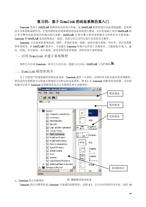
图 8.3 Simulink 的公共模型库
50
2、Simulink 的专业模型库 前面对 Simulink 的公共模型库做了详细的介绍,除了公共模型库外,Simulink 中还集成了许多面向
不同专业的专业模型库,不同领域的系统设计师可以使用这些系统模块快速构建自己的系统模型,然后 在此基础上进行系统的仿真、分析,从而完成设计任务。下面仅介绍几种控制工程师可能用到的专业模 型库的主要功能。 1)航空航天模型库(Aerospace Blockset)
stateflow仿真优点

stateflow仿真优点以stateflow仿真优点为标题,写一篇文章。
在系统建模和仿真领域,stateflow是一种被广泛使用的工具,它提供了一种直观而强大的方法来描述和模拟系统的行为。
stateflow的仿真优点包括以下几个方面。
stateflow提供了一种直观的图形化建模界面,使得系统的行为可以用状态图的形式进行描述。
这种图形化建模方式不仅使得系统的行为更加可视化,而且可以更容易理解和检查系统的逻辑。
与传统的文本编程相比,stateflow的图形化界面可以更直观地展示系统的状态转移和事件触发,使得系统的建模更加高效和准确。
stateflow具有强大的仿真能力。
它可以对系统进行高度精确的仿真,模拟系统在不同状态下的行为,并可以根据不同的输入条件和事件触发进行相应的响应。
stateflow提供了丰富的仿真工具和功能,可以对系统进行逐步调试和分析,帮助开发人员快速定位问题并进行修复。
通过stateflow的仿真功能,系统的开发和测试过程变得更加高效和可靠。
第三,stateflow具有灵活的扩展性。
它可以与其他建模和仿真工具进行无缝集成,如Simulink等,从而实现更复杂系统的仿真和分析。
stateflow可以与Simulink中的模型进行交互,通过对系统的状态进行建模和仿真,可以更好地理解系统的行为和性能。
同时,stateflow还提供了丰富的函数库和工具箱,可以满足不同系统建模和仿真的需求。
stateflow还具有良好的可视化和文档生成能力。
它可以自动生成系统的状态图和状态转移图,并支持导出为各种格式,如PDF、Word等。
通过这些可视化和文档生成功能,开发人员可以更好地与团队成员进行沟通和交流,并可以方便地记录系统的设计和实现过程。
stateflow作为一种强大的系统建模和仿真工具,具有直观的图形化建模界面、强大的仿真能力、灵活的扩展性以及良好的可视化和文档生成能力。
它不仅可以提高系统开发的效率和可靠性,而且可以帮助开发人员更好地理解和分析系统的行为和性能。
基于Web的DCS数据监控系统设计与实现
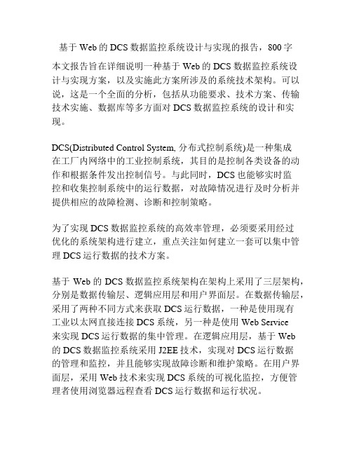
基于Web的DCS数据监控系统设计与实现的报告,800字本文报告旨在详细说明一种基于Web的DCS数据监控系统设计与实现方案,以及实施此方案所涉及的系统技术架构。
可以说,这是一个全面的分析,包括从功能要求、技术方案、传输技术实施、数据库等多方面对DCS数据监控系统的设计和实现。
DCS(Distributed Control System, 分布式控制系统)是一种集成在工厂内网络中的工业控制系统,其目的是控制各类设备的动作和根据条件发出控制信号。
与此同时,DCS也能够实时监控和收集控制系统中的运行数据,对故障情况进行及时分析并提供相应的故障检测、诊断和控制策略。
为了实现DCS数据监控系统的高效率管理,必须要采用经过优化的系统架构进行建立,重点关注如何建立一套可以集中管理DCS运行数据的技术方案。
基于Web的DCS数据监控系统架构在架构上采用了三层架构,分别是数据传输层、逻辑应用层和用户界面层。
在数据传输层,采用了两种不同方式来获取DCS运行数据,一种是使用现有工业以太网直接连接DCS系统,另一种是使用 Web Service来实现DCS运行数据的集中管理。
在逻辑应用层,基于Web的DCS数据监控系统采用J2EE技术,实现对DCS运行数据的管理和监控,并且能够实现故障诊断和维护策略。
在用户界面层,采用Web技术来实现DCS系统的可视化监控,方便管理者使用浏览器远程查看DCS运行数据和运行状况。
因此,基于Web的DCS数据监控系统的实施,可以将传统的繁琐的DCS监控系统变得简单易用,可有效改善管理者查看DCS运行状况的效率,加快DCS设备故障诊断和维护的策略,从而提高工业系统的运行效率和可靠性。
Stateflow使用方法
简单的使用了交汇连接工具的实例:
事实上,交汇连接工具的合理使用可以完 成非常复杂的逻辑关系: 例如实现如下if_then 判断功能
if [Cond1] { Action1 if [Cond2] { Action2 }elseif [Cond3]{ Action3 } }
在MATLAB窗口中点开Simulink,在Simulink的library中点开 Stateflow,将chart拖入一个新建的文件中,结果如下图所示。
双 击 untitled* 窗口中的Stateflow 模块打开如图下图 所示的Stateflow 编 辑界面,用户可以在此窗口中编辑所需的Stateflow 模型。Stateflow 提供了 强大的图形编辑功能,用户可以使用它描述很复杂的逻辑关系式。
还可实现For 循环功能:
6、图形函数的设置及其调用
前面例子中的Stateflow 图中多次利用了条件关系式 [temp>=120]。对于这种多次使用的关系式,我们可以设置一 个图形函数Function,使用时调用这个函数即可。
状态流的图形函数是使用交汇连接工具和状态迁移工具绘制 的状态流图形。
事件的范围(Scope )有三种选择:Local 是指利用本 Stateflow 图形 界面产生的触发事件; Input from Simulink 是指从 Simulink 模型引入 事件至 Stateflow 图形界面;Output to Simulink 是指将Stateflow 图 形界面产生的事件输出到Simulink 模型中。 事件的触发方式(Trigger)有四种选择:Either、Rising、Falling 和 Function Call 。其中选择Rising 或Falling 分别指利用事件的上升沿或 下 降 沿 触 发 ; Either 是 指 不 管 上 升 沿 还 是 下 降 沿 事 件 均 可 以 触 发 ; Function Call 是一种函数调用的触发方式。
xpc-target

xPC Target Turnkey real-time testing solution. Once you connect to your hardware under test, you can run your Simulink and Stateflow models in real time and verify your designs.Creating a Real-Time Testing EnvironmentSimulink Coder™, and a C compiler to the target computer via a single TCP/IP or RS-232 communications link. You then connect the target computer to your hardware under test and download code generated by Simulink Coder from a Simulink model to the target computer via the communications link.Once you make the connections, you can:▪Access and interactively control the target computer and xPC Target application▪Tune parameters before, during, and after real-time execution▪Acquire, view, and log signal dataComponents of an xPC Target real-time testing environment.Interfacing with Target Computer HardwareUsing xPC Target in a real-time testing environment requires a target computer with I/O modules or protocol support.xPC Target Turnkey provides ready-to-use configurations, from which you can select a real-time target machine that meets the performance requirements of your real-time testing application. xPC Target Turnkey offers a variety of form factors and I/O modules suitable for desktop, laboratory, or in-vehicle real-time testing solutions.xPC Target also includes I/O drivers and functions that support additional target computer hardware and I/O boards that you specify and purchase directly from the hardware manufacturer.Ready-to-use xPC Target Turnkey real-time target machines in a variety of form factors suitable for desktop, lab, orin-vehicle environments.Accessing and Controlling an xPC Target ApplicationYou create an xPC Target application using xPC Target with Simulink Coder to automatically generate and compile a C/C++ code representation of a Simulink model. You then download the target application via a LAN (Ethernet) connection from the host computer to the target computer.xPC Target enables you to access the target application and control it directly from the host computer using either the xPC Target Explorer tool or the MATLAB®command line. You can download your target application, startand stop real-time test execution, change the sample time and stop time, and modify other target application properties.xPC Target also provides flexible APIs for MATLAB, .NET, C, and COM that let you programmatically control the target application running on the target computer.Once you have a working xPC Target application, you can run the application in standalone mode using xPC Target Embedded Option. In standalone mode, the xPC Target application automatically starts and executes on the target computer without requiring a host computer.Tuning Parameters, Monitoring Signals, and Acquiring DataxPC Target lets you tune and optimize parameter values before, during, and after real-time execution of models on the target computer using Simulink external mode, xPC Target Explorer, or the MATLAB command-line interface.Using xPC Target via Simulink External Mode. You can work with xPC Target and the Simulink model (left) to control real-time operation, tune parameters, and view the results directly in Stateflow (middle) and in a Simulink Scope block (top right).To monitor and acquire data, xPC Target includes scopes for both the host and target computers. Scopes support several trigger modes you can use to control the acquisition, timing, and duration of data collection. You can also display multiple signals in a single scope and attach multiple scopes to a single model.Signal monitoring enables you to view signal values at the current sample rate. Signal tracing lets you capture, store, and display bursts of data, similar to the behavior of a digital oscilloscope. Signal logging lets you acquire and store signals during the entire test execution. You can then upload the logged data to the host computer for signal display, analysis, or archiving.Programming FPGA BoardsUsing code generated by Simulink HDL Coder, you can automatically program FPGA boards within xPC Target Turnkey systems. You can build reconfigurable I/O or execute high-speed algorithms on an FPGA connected to a model running in real time with xPC Target.Product Details, Demos, and System Requirements/products/xpctargetTrial Software/trialrequestSales/contactsalesTechnical Support/support You can use Simulink, Stateflow, or MATLAB function blocks to model the algorithm you want to run on the FPGA board. Once you are satisfied with the simulated results, the Simulink HDL Coder Workflow Advisor walks you through the process to instantiate your design, generate a bitstream for the selected FPGA, and create an xPC Target interface subsystem for programming and communicating with the FPGA. The interface handles the details of programming the FPGA (requiring no HDL experience), so you can focus on your real-time testingtasks.Programming FPGA boards for xPC Target Turnkey real-time target machines using Simulink HDL Coder Workflow Advisor.ResourcesOnline User Community /matlabcentral Training Services /training Third-Party Products and Services /connections Worldwide Contacts /contact。
stateflow例子
stateflow例子什么是Stateflow?Stateflow是一种用于建模和仿真动态系统的MATLAB/Simulink工具。
它通过定义状态、转移和行为规则的方式,将系统行为以图形化的形式表示出来。
Stateflow可以用于建模诸如控制系统、通信协议、状态机等各种动态系统。
特别是对于复杂的系统,Stateflow可以提供清晰可视化的方式,使得系统设计者和开发者能够更好地理解和分析系统行为。
Stateflow 的特点Stateflow具有以下几个主要特点:1. 图形化建模:Stateflow通过图形化的方式提供了直观的建模环境。
用户可以通过拖拽和连接不同的图元(如状态、转移、事件等)来构建系统模型。
同时,Stateflow还提供了多种可视化效果,如状态颜色、转移动画等,使得系统模型更加生动。
2. 事件驱动:Stateflow的行为规则是以事件驱动的方式执行的。
系统可以通过外部事件、内部事件、时间触发事件等方式触发状态变化和操作执行。
这种事件驱动的方式使得模型可扩展性强,能够适应不同的应用场景。
3. 状态机建模:Stateflow提供了丰富的状态机建模功能。
用户可以定义不同的状态、转移条件和动作,以指定系统行为。
状态机的模型可以很好地表示系统的并行行为、历史状态、嵌套状态等复杂行为,提供了一种清晰明了的建模方式。
4. 可执行代码生成:Stateflow可以生成可执行的MATLAB代码或C代码。
这使得Stateflow可以与其他MATLAB/Simulink模块无缝集成,并且可以在硬件平台上部署和运行。
生成的代码可以用于实时仿真、嵌入式系统开发等应用领域。
Stateflow的应用Stateflow在各种领域都有广泛的应用。
以下是一些常见的应用场景:1. 控制系统设计:Stateflow被广泛应用于控制系统的建模和仿真。
通过定义状态和转移,可以方便地描述控制算法的状态转换和动作执行。
同时,Stateflow还提供了丰富的调试和验证工具,有助于设计和优化控制系统。
stateflow chart用法

Stateflow Chart用法在软件开发中,Stateflow Chart是一种流程图形式的建模工具,它能够对系统的状态和事件进行建模和分析。
Stateflow Chart的使用在很多领域都有广泛的应用,比如控制系统、通信系统、汽车电子系统等等。
在本文中,我们将探讨Stateflow Chart的基本用法,并且分析其在不同领域的应用。
1. Stateflow Chart的基本概念Stateflow Chart是一种基于状态的建模工具,它通过状态、转移和动作来描述系统的行为。
在Stateflow Chart中,状态用方框表示,转移用箭头表示,动作用椭圆形表示。
通过这些基本元素的组合,可以描述出系统在不同状态下的行为,并且可以清晰地展现系统的状态转移过程。
2. Stateflow Chart的应用在控制系统中,Stateflow Chart常常用于描述系统的控制逻辑。
比如在汽车防抱死系统(ABS)中,Stateflow Chart可以很好地描述出车轮在不同状态下的制动逻辑。
在通信系统中,Stateflow Chart可以描述出数据包在网络中的传输过程。
在汽车电子系统中,Stateflow Chart 可以描述出车辆在不同行驶状态下的控制逻辑。
3. Stateflow Chart的优势与传统的文字描述相比,Stateflow Chart能够更直观地展现系统的行为。
通过图形化的表示,可以更容易地理解系统的状态转移过程。
另外,Stateflow Chart还可以方便地与Simulink等建模工具结合使用,从而可以对系统进行更全面的建模和分析。
4. 对Stateflow Chart的个人观点和理解我认为Stateflow Chart作为一种建模工具,在系统建模和分析中具有很大的优势。
它不仅能够更形象地展现系统的行为,还能够方便地与其他建模工具结合使用。
在我的工作中,我经常会使用Stateflow Chart来描述系统的控制逻辑,它确实为我提供了很大的方便。
Stateflow教程
在图形对象面板的连接节点图标 上按下鼠标左键并保持, 将状态拖 放到Stateflow 编辑器的空白区域中。
节点上单击鼠标右键,通过弹出的快捷菜单 执行 Properties 命令,进入属性框
3. 创建转移 转移是 Stateflow 框图中最常见的图形元素之一,无论是包含状态的状态图中还是没
有状态的流程图中,几乎都存在转移。转移描述的是有限状态系统内的逻辑流。转移管理 了当系统从当前状态改变时,这个系统可能发生的模式改变。当转移发生时,源状态变为 非活动的状态, 目标状态变为活动的状态。转移是带有箭头的线,这就使整个状态图或者 流程图成为了“有向图”,状态或者流程之间的转换, 将直接受到转移方向的约束。
如果用户设置事件的 Scope 属性为 Input from Simulink 或者 Output to Simulink,则添加事件的对话框会发生变化,
Trigger 属性:Trigger 属性总共有四个可能值, 分别为 Either、 Falling、 Rising 和 Function Call。在 Simulink 条件执行子系统中, 特别是 在使能或者触发子系统中, 触发子系统工作的 触发源就具有不同属性。 触发子系统的触发源 与这里的 Trigger 属性的意义完全一样, 分别 为双边沿触发、 下降沿触发、 上升沿触发。 Function Call(函数调用)是一类比较特殊的触发 属性
第一章 创建状态图
ØStateflow编辑器 Ø创建和编辑状态图
创建 Simulink 模型 1. 直接在 MATLAB 命令行窗体中键入指令 sfnew 2. 打开 Simulink 库浏览器,
在库浏览器中找到 Stateflow 的模块库
双击模型文件或者库文件中的 Stateflow 图块打开 Stateflow 编辑器
xPC-target-real-time-control-and-simulation-system讲课稿

➢ 主机和目标PC机之间的通讯
通过单一通信方式连接主机和目标计算机。用户在主机上开发 Simulink模型,下载到目标机上并实时运行。用户指令、参数更新和 信号数据交互也使用同样的通信接口。客户可以选择RS-232, TCP/IP方式进行通信
➢ 利用xPCLabDesk作为上位机GUI
xPC Target有两个很强的应用程序接口,分别是:xPC Target API和 COM API。用户可以来创建用户自己的GUI完成这些功能 。据说效果 不好。
➢ 实时调整参数。
➢ 根据处理器的性能水平、模型规模和I/O复杂程度,模型系统 sample time最高可达100KHz 。
➢ 在matlab提供的设备驱动库里,支持300多种商业I/O板卡。
➢ 开放的硬件驱动环境,支持用户开发系统集成方和硬件生产方硬 件设备的驱动程序。
强大功能
➢ 高效的实时内核
➢ 编写用户自定设备驱动
xPC Target提供大量的第三方板卡驱动。这些驱动在xPC Target库以 Simulink模块的形式提供。如果用户板卡的驱动没有提供,可以自己
编写。驱动开发提供了工具、向导、示例和源码来帮助用户。
xPC Target支持的第三方板卡驱动
➢ 在线调整参数
xPC Target提供几种在线调参的办法。目标程序下载以后,用户可以 使用命令行接口或目标机浏览器来修改参数。还可以通过Simulink外 部模式进行参数的调整,在这种模式中,Simulink框图运行在主机上 作为GUI界面。一旦改变了Simulink模型中任何的参数,新的参数会 立刻下载到目标机上,这时用户观察的是最新程序的运行情况。
xPC target real-time control and simulation system
基于xPC-target的快速控制原型技术快速控制原型技术

Design)
4.1 快速控制原型技术
基于MATLAB的快速控制原型系统开发构架
4.1 快速控制原型技术
MATLAB自动化代码生成工具
在MATLAB产品族中,自动化的代码生成工具主要有RealTime Workshop(RTW)和Stateflow Coder,这两种代码生成工 具可以直接将Simulink的模型框图和Stateflow的状态图转换成 高效、优化的程序代码。利用RTW生成的代码简洁、可靠、易 读。目前RTW支持生成标准的C语言代码,并且具备了生成其 他语言代码的能力。整个代码的生成、编译以及相应的目标下 载过程都是自动完成的。Mathworks公司针对不同的实时或非 实时操作系统平台开发了相应的目标选项,以配合不同的软、 硬件系统完成快速控制原型(Rapid Control Prototype)开发、 硬件在回路的实时仿真(Hardware-in-Loop)、产品代码生成等 工作。
4.1 快速控制原型技术
快速控制原型技术的软件支撑环境:
Simulink
Stateflow
Stateflow Coder
Real-Time Workshop
Generic Real-Time Interface
Real-Time Target
Real-Time Target
Real-Time Workshop的体系结构
第四章 快速控制原型技术
1. 快速控制原型技术 2. xPC-target简介 3. xPC-target的安装和配置 4. xPC-target的基本使用方法 5. xPC-target的应用实例
4.1 快速控制原型技术
matlab R2015a新功能及安装教程

matlab R2015a新功能MathWorks 今天宣布推出其 MATLAB 和 Simulink 产品系列的 Release 2015a (R2015a) 版本。
R2015a 包括 MATLAB 和 Simulink 的新功能以及 81 个其他产品的更新和补丁修复。
MATLAB 产品系列MATLAB:Raspberry Pi 和网络摄像头硬件支持包Optimization Toolbox:混合整数线性规划 (MILP) 解算器Statistics Toolbox:为每对象具有多个测量值的数据进行重复测量数据建模Image Processing Toolbox:使用 MATLAB Coder 为 25 个函数生成 C 代码,为 5 个函数实现 GPU 加速Econometrics Toolbox:状态-空间模型、缺失数据情况下自校准的卡尔曼滤波器,以及ARIMA/GARCH 模型性能增强Financial Instruments Toolbox:对偶曲线构建,用于计算信用敞口和敞口概况的函数,以及利率上限、利率下限和掉期期权的布莱克模型定价SimBiology:提供用于模型开发的模型估算和桌面增强的统一函数System Identification Toolbox:递归最小二乘估算器和在线模型参数估算模块MATLAB Production Server:实现客户端与服务器之间的安全通讯以及动态请求创建Simulink 产品系列Simulink:用于定义和管理与模型关联的设计数据的数据字典。
Simulink:用于多核处理器和 FPGA 的算法分割和定位的单一模型工作流程Simulink:为LEGO MINDSTORMS EV3、Arduino Due 和 Samsung Galaxy Android 设备提供内置支持Stateflow:提供了上下文相关的 Tab 键自动补全功能来完成状态图Simulink Real-Time:仪表板、高分辨率目标显示器和FlexRay 协议支持,以及合并了xPC Target 和 xPC Target Embedded Option 的功能SimMechanics:STEP 文件导入和接口的总约束力计算Simulink Report Generator:用于在 Simulink 视图中丰富显示内容的对象检查器和通知程序用于在 MATLAB 和 Simulink 中进行设计的系统工具箱 (System Toolbox)Computer Vision System Toolbox:立体视觉和光学字符识别 (OCR) 功能代码生成Embedded Coder:支持将 AUTOSAR 工具的变更合并到 Simulink 模型中Embedded Coder:ARM Cortex-A 使用 Ne10 库优化了代码生成HDL Coder:枚举数据类型支持和时钟频率驱动的自动流水线操作HDL Verifier:通过JTAG对Altera 硬件进行 FPGA 在环仿真matlab 2015a安装教程1、解压文件,运行“setup.exe”开始安装2、选择“使用文件安装秘钥”点击下一步3、允许用户协议,选择“是”点击下一步4、选择“我已有我的许可证的文件安装秘钥”,输入序列号“58691-35070-25550-28046-23042”5、选择安装目录,需要占用11GB磁盘空间6、选择安装的功能,默认即可7、等待安装完成8、安装完成后,进入安装包,进入Crack文件夹,将里面的七个对象复制到安装目录下覆盖源文件,安装目录默认为C:\Program Files\MATLAB\MATLAB ProductionServer\R2015a9、进入安装目录bin文件夹,运行“matlab.exe”,在弹出的激活界面选择“在不使用Internet的情况下手动激活”10、载入激活文件“lic_standalone.dat"11、激活成功,再次运行即可体验新版的matlab 2015a。
stateflow注释
stateflow注释【最新版】目录1.Stateflow 简介2.Stateflow 注释的作用和分类3.Stateflow 注释的语法规则4.Stateflow 注释的实际应用5.总结正文1.Stateflow 简介Stateflow 是一种基于有限状态自动机(FSM)的建模和仿真工具,广泛应用于控制系统和嵌入式系统的开发和测试中。
Stateflow 可以帮助工程师设计和分析复杂的控制逻辑,并生成可执行的代码。
2.Stateflow 注释的作用和分类Stateflow 注释是对 Stateflow 图中的状态、事件和动作等元素进行描述和解释的文本信息。
它可以提高代码的可读性和可维护性,对于团队协作和大型项目的管理具有重要意义。
Stateflow 注释主要分为以下几类:- 状态注释:对状态机的某个状态进行描述,包括状态的输入输出变量、触发条件等。
- 事件注释:对状态机中的事件进行描述,包括事件的名称、触发条件、处理动作等。
- 动作注释:对状态机中的动作进行描述,包括动作的名称、功能、执行条件等。
- 其他注释:对状态机中的其他元素进行描述,如数据类型、常量、变量等。
3.Stateflow 注释的语法规则Stateflow 注释遵循一定的语法规则,主要包括以下几点:- 注释以双斜杠“//”开头,可以跨行。
- 注释内容需简洁明了,描述清楚注释对象的属性和功能。
- 注释中可以使用变量、常量和函数等 Stateflow 语言元素。
- 注释应当及时更新,与代码的修改保持一致。
4.Stateflow 注释的实际应用在实际的 Stateflow 编程过程中,注释的应用至关重要。
以下是一些注释的实际应用场景:- 对复杂的控制逻辑进行描述,提高代码的可读性。
- 对状态机的各个状态、事件和动作进行详细解释,便于团队成员理解和维护。
- 对状态机中的关键算法和技巧进行说明,方便后续的优化和改进。
- 对状态机中的异常处理和边界条件进行描述,提高代码的健壮性。
sFlow RFC3176
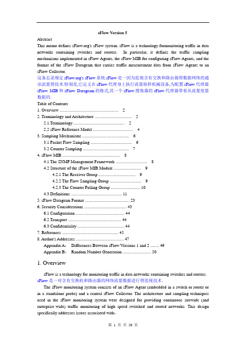
sFlow V ersion 5AbstractThis memo defines 's sFlow system. sFlow is a technology formonitoring traffic in data networks containing switches and routers. In particular, it defines the traffic sampling mechanisms implemented in sFlow Agents, the sFlow MIB for configuring sFlow Agents, and the format of the sFlow Datagram that carries traffic measurement data from sFlow Agents to an sFlow Collector.这备忘录规定's sFlow系统.sFlow是一因为监视含有交换和路由器得数据网络的通讯流量得技术.特别是,它定义在sFlow代理身上执行流量取样机械设备,为配置sFlow代理器sFlow MIB和sFlow Datagram的格式,其一个sFlow搜集器的sFlow代理器带着从流量度量数据的.Table of Contents1. Overview (2)2. Terminology and Architecture (2)2.1 Terminology (2)2.2 sFlow Reference Model (4)3. Sampling Mechanisms (6)3.1 Packet Flow Sampling (6)3.2 Counter Sampling (7)4. sFlow MIB (8)4.1 The SNMP Management Framework (8)4.2 Structure of the sFlow MIB Module (9)4.2.1 The Receiver Group (9)4.2.2 The Flow Sampling Group (9)4.2.3 The Counter Polling Group (10)4.3 Definitions (11)5. sFlow Datagram Format (23)6. Security Considerations (43)6.1 Configuration (44)6.2 Transport (44)6.3 Confidentiality (44)7. References (45)8. Author's Addresses (47)Appendix A:Differences Between sFlow V ersions 1 and 2 (49)Appendix B:Random Number Generation (50)1. OverviewsFlow is a technology for monitoring traffic in data networks containing switches and routers. sFlow是一对含有交换机和路由器的网络流量数据进行得监视技术.The sFlow monitoring system consists of an sFlow Agent (embedded in a switch or router or in a standalone probe) and a central sFlow Collector. The architecture and sampling techniques used in the sFlow monitoring system were designed for providing continuous sitewide (and enterprise-wide) traffic monitoring of high speed switched and routed networks. This design specifically addresses issues associated with:sFlow监视系统由sFlow Agent(嵌入到交换机和路由器或单独的探测器中)和central sFlow Collector.使用在sFlow监视器系统的结构和采样技术都有计划的提供连续的网点范围(企业范围)的高速的交换和路由的网络工作的流量监视.o Accurately monitoring network traffic at Gigabit speeds and higher.准确得监视Gigabit速度及更高流量网络o Scaling to monitor tens of thousands of agents from a single sFlow Collector.依比例决定从单独得一个sFlow搜集器监视数以万计的代理器的.o Extremely low cost sFlow Agent implementation. 极其低价钱为sFlow代理工具The sFlow Agent uses sampling technology to capture traffic statistics from the device it is monitoring. sFlow Datagrams are used to immediately forward the sampled traffic statistics to an sFlow Collector for analysis.sFlow代理器使用取样技术捕获从它监视设备中进行流量统计.使用sFlow Datagrams为分析立即转发抽样检查流量统计给一个sFlow搜集器.This document describes the sampling mechanisms used by the sFlow Agent, the SFLOW MIB used by the sFlow Collector to control the sFlow Agent, and the sFlow Datagram Format used by the sFlow Agent to send traffic data to the sFlow Collector.这文件描绘经过sFlow代理器使用取样机制,SFLOW MIB经过sFlow搜集器通常控制sFlow 代理器,和sFlow Datagram格式经过sFlow代理器通常把流量数据寄给sFlow搜集器.This memo describes sFlow version 5. It replaces sFlow version 4 described in RFC 3176 [1]. The differences between sFlow versions 4 and 5 are described in Appendix A.这备忘录描绘sFlow版本5.它取代在RFC 3176[1]中描绘sFlow第4版.sFlow第4和5版之间的差异在附录A中被描绘.2. Terminology and ArchitectureThis section defines the elements of the sFlow system.这部分解释sFlow系统的基本原理2.1 TerminologyThe terms used to specify the sFlow architecture are defined here for reference.这些条款作为使用sFlow体系结构的参考.o Network Device:A piece of network equipment, such as a switch or router, that forwards data packets.网络设备:一台像交换器、路由器这样的转发数据包的网络设备o Data Source:A Data Source refers to a location within a Network Device that can make traffic measurements. Possible Data Sources include interfaces, physical entities within the device such as the backplane and VLANs. Each Data Source has access to a subset of the traffic flowing through the device. The type and number of Data Sources needed to completely monitor a device will depend on the internal architecture of that device. Typically a Data Source is defined for each physical interface on the device since this ensures that every packet transiting the device to be observed.数据源:在一定位置上能够产生流量检测的网络设备.可能数据源包括接口、在例如像backplane和VLANs这样的设备上的物理实体.每个数据源能够访问到通过设备数据流量的子集.一些类型和数量的数据源需要完整的监视设备将依赖设备的内部结构体系.典型的数据源为定义了每个设备上的物理接口以确保每个通过传输的包的观察设备o Packet Flow:A Packet Flow is defined as the path or trajectory that a packet takes througha Network Device (i.e. the path that a packet takes as it is received on one interface, is subject to a switching/routing decision and is then sent on another interface. In the case of a one-armed router, the source and destination interface could be the same. In the case of a broadcast or multicast packet there may be multiple destination interfaces).信息包流:定义为包通过网络设备的路径或轨迹(例如一个接口接受包,并由路由器或交换机决定是否发送给另外的接口的路径.在one_arm路由器的情况下,源和目的路由接口应当一样.在广播或多播包的情况下,这将多目的接口)o Packet Flow Sampling:Packet Flow Sampling refers to the random selection of a fraction of the Packet Flows observed at a Data Source.包流采样:在数据源上随机选择部分用来观察的包流.o Sampling Rate:The Sampling Rate specifies the ratio of packets observed at the Data Source to the samples generated. For example a sampling rate of 100 specifies that, on average, 1 sample will be generated for every 100 packets observed.采样率:采样包和观察源数据的比率.例如抽样率为100,那么平均从100个要观察的包中抽取1个包o Packet Flow Record:A Packet Flow Record describes the attributes of a Packet Flow. There are two types of information in a flow record:1 Information on the packet itself, typically a packet header, packet length and packet encapsulation.2 Information about the path the packet took through the device, including information relating to the selection of the forwarding path.包流记录:它描述了一个包流的特征.这里有2个信息在包流记录中:(1)包自己的信息,代表的有包头,包长度和包封装(2)关于包通过设备的路径信息,包含了相关的选择前向路径o Counter Sampling:Periodic sampling or polling of counters associated with a Data Source. 采样计数器:数据源关联的周期取样或者投票的计数器.o Sampling Interval:The time period between successive Counter Samples.取样时间间隔:连续计数采样之间的时间周期.o Counter Record:A record containing counter values associated with a Data Source at the end of a Sampling Interval.计数器记录:包含在采样周期结尾的与数据源关联的计数值的记录o sFlow Instance:An sFlow Instance refers to a measurement process associated with a Data Source.There may be one or more sFlow Instances associated with a single Data Source.Each sFlow Instance operates independently of other sFlow Instances, for example if Packet Flow Sampling instances each have their own Sampling Rates and Counter Sampling instaces have their own Sampling Interval.sFlow实例:与数据源关联的测量处理.可以提供一个或多个sFlow实例关联在一个数据源上.每个sFlow 实例独立于其他的sFlow 实例,例如,每个包采样实例都有他们自己的采样率和采样计数器在他们自己的采样周期中o sFlow Agent:The sFlow Agent provides an interface for configuring the sFlow Instances within a device. The sFlow Agent may support command line and/or SNMP based configuration.The agent is also responsible for maintaining measurement sessions with sFlow Collectors. It marshals data into sFlow Datagrams to send to sFlow Collectors. The sFlow Agent frees resources when a session expires.sFlow代理器:给设备中的sFlow实例的配置提供接口,它提供基于命令行或基于SNMP配置.它还负责对sFlow搜集器的维修测量对话.它整理数据到sFlow Datagram 发送到sFlow搜集器.sFlow代理在对话过期后释放资源.o sFlow Sub-Agent:In the case where sFlow is implemented on a distributed device architecture it may be desireable to distribute the sFlow Agent functionality. Each sFlow Sub-Agent is responsible for a particular subset of Data Sources.sFlow子代理器:在sFlow在分布结构设备上执行情况下可以是描述sFlow代理器的性能的愿望其sFlow有关一分配设备体系结构被执行.每一sFlow子代理依赖于数据源的特殊子集.o sFlow Collector:An sFlow Collector receives sFlow Datagrams from one or more sFlow Agents. The sFlow Collector may also configure sFlow Instances using the configuration mechanisms provided by the sFlow Agent.sFlow搜集器:一个sFlow搜集器从一个或更多sFlow代理器收到sFlow Datagrams.sFlow搜集器可以也配置sFlow实例使用经过sFlow代理器提供配置机械设备.o sFlow Datagram:The sFlow Datagram is a UDP datagram that contains the measurement data, and information about the measurement source and process. The format of the sFlow Datagram is defined in this document.sFlowDatagram:sFlow Datagram是一UDP datagram,其含有度量数据和关于度量来源和过程的信息的.sFlow Datagram的格式在这文件中被确定.2.2 sFlow Reference ModelThe figure below shows the relationships between the different entities within an sFlow system.下面图示展示了一sFlow系统内不同实体之间的关系.An sFlow Collector makes use of SNMP to communicate with an sFlow Agent in order toconfigure sFlow monitoring on a Network Device. The sFlow MIB describes the managed objects needed to configure an sFlow Agent. Packet Flow Sampling and Counter Sampling is performed by sFlow Instances associated with individual Data Sources within the sFlow Agent. In order to perform Packet Flow Sampling, an sFlow Instance is configured with a Sampling Rate. The Packet Flow sampling process results in the generation of Packet Flow Records. In order to perform Counter Sampling, an sFlow Instance is configured with a Sampling Interval. The Counter Sampling process results in the generation of Counter Records. The sFlow Agent collects Counter Records and Packet Flow Records and sends them in the form of sFlow Datagrams to sFlow Collectors.SFlow 搜集器为了配置sFlow 监视网络设备使用SNMP与sFlow 代理通讯. SFlow MIB 描述管理目标需要配置在sFlow Agent.包采样和计数采样在sFlow 代理上的一个个体数据源上的sFlow实例来执行.为了执行包流采样,要配置sFlow实例的采样率.包流采样处理结果由包流记录产生.为了执行计数器采样,sFlow实例配置采样间隔.计数器采样处理结果由计数器记录产生.sFlow代理搜集计数器记录和包流记录并以sFlow数据报形式发送他们到sFlow搜集器.3. Sampling MechanismsThe sFlow Agent uses two forms of sampling:statistical packet-based sampling of switched or routed Packet Flows, and time-based sampling of counters.sFlow代理用2种格式采样:基于包统计交换或路由包流的采样;基于时间和计数器的采样3.1 Packet Flow SamplingThe Packet Flow Sampling mechanism carried out by each sFlow Instance must ensure that any packet observed at a Data Source has an equal chance of being sampled, irrespective of the Packet Flow(s) to which it belongs.包流采样机制是由每个sFlow实例必须确认观察数据源上的任何包有平等的机会被抽样到.不考虑包流属于谁.Packet Flow Sampling is accomplished as follows:When a packet arrives on an interface, the Network Device makes a filtering decision to determines whether the packet should be dropped. If the packet is not filtered a destination interface is assigned by the switching/routing function. At this point a decision is made on whether or not to sample the packet. The mechanism involves a counter that is decremented with each packet.When the counter reaches zero a sample is taken. Whether or not a sample is taken, the counter Total_Packets is incremented.Total_Packets is a count of all the packets that could have been sampled.执行流程:当一个包到达接口,网络设备作出是否丢弃它的过滤.如果包没有被交换或路由功能过滤掉一个目的接口.在这指出决定是否采样包.这个机制包括计数器对每一个包递减.当计数器到到0,一个采样就产生.无论采样是否发生,计数器Total_Packts增加.Total_Packets是计算所有被采样的包数量Taking a sample involves either copying the packet's header, or extracting features from the packet.See sFlow Datagram Format for a description of the different forms of sample.Every time a sample is taken, the counter Total_Samples, is incremented. Total_Samples is a count of the number of samples generated.Samples are sent by the sFlow Instance to the sFlow Agent for processing.The sample includes the packet information, and the values of the Total_Packets and Total_Samples counters.The sFlow Agent may then use the samples to obtain additionalinformation about the packet's trajectory through the device. Such information depends on the forwarding functions of the device. Examples of trajectory information provided are source and destination interface, source and destination VLAN, next hop subnet, full AS path. Details of the forwarding information are given in the sFlow Datagram Format.包采样包括拷贝包的头或从包中提取特征.(看描述不同采样格式的sFlow数据报格式).每次采样,计数器Total_samples都增加.Total_samples是统计采样发生数量的.采样发送到sFlow 代理的sFlow实例处理. 采样包括包信息和Total_Packets和Total_samples计数器.SFlow代理要用采样获得关于包通过设备路径的的另外信息.一些信息依赖设备的转发功能.路径信息的例子提供源和目的接口,源和目的VLAN,子网下一跳,全AS-path.详细的转发信息付给sFlow 数据报格式When a sample is taken, the counter indicating how many packets to skip before taking the next sample should be reset. The value of the counter should be set to a random integer where the sequence of random integers used over time should be such that:当采样发生,计数器指示出下一次采样发生前有多少个包跳过,计数器的值被设为随机的一个int型数,(1) Total_Packets/Total_Samples = Sampling RateAn alternative strategy for Packet Flow Sampling is to generate a random number for each packet, compare the random number to a preset threshold and take a sample whenever the random number is smaller than the threshold value. Calculation of an appropriate threshold value depends on the characteristics of the random number generator, however, the resulting sample stream must still satisfy包流采样的选择策略是每个包产生一个随机数,比较随机数和提前设定的阈值,如果小于阈值就采样.计算一个合适的阈值依赖于特定的随机数产生器,但是,随之发生采样结果必须去更加完善.Appendix B further discusses the requirements for the random number generator.附录B进一步讨论随机数产生的要求.3.2 Counter SamplingThe primary objective of the Counter Sampling is to efficiently, periodically export counters associated with Data Sources.计数器取样的基本目标是要高效的、周期性地输出把计数器和数据源联系起来.Typically a Data Source will be associated with each interface on the device that can be an ingress or egress interface for Packet Flows.These interface Data Sources will then be used to export counters relating to the interfaces.典型一数据源将被把和每一在能是一进入的设备上接口联系起来或者那时为包Flows.这些数据源接口将被使用出口数据.A maximum Sampling Interval is assigned to each sFlow Instance associated with an interface Data Source, but the sFlow Agent is free to schedule polling in order maximize internal efficiency. 给分配一最大取样时间间隔但是sFlow代理器是对顺序投票明细表自由使内部效率增至最大每一sFlow实例把和联系起来一接口数据源.Packet Flow Sampling and Counter Sampling are designed as part of an integrated system. Both types of sample are combined in sFlow Datagrams. Since Packet Flow Sampling will cause a steady, but random, stream of sFlow Datagrams to be sent to the sFlow Collector, counter samples may be taken opportunistically in order to fill these datagrams.包流动取样和计数器取样作为一综合系统的一部分被设计.两个类型的样品在sFlow Datagrams中被合并.自包流动取样将给一固定的异性朋友但是任意行动造成以来,为了填补这些,计数器样品可以机会主义地被拿datagrams股sFlow Datagrams把寄给sFlow搜集器.One strategy for counter sampling has the sFlow Agent keep a list of counter sources being sampled. When a Packet Flow Sample is generated the sFlow Agent examines the list and adds counters to the sample datagram, least recently sampled first. Counters are only added to the datagram if the sources are within a short period, 5 seconds say, of failing to meet the required Sampling Interval (see sFlowCounterSamplingInterval in SFLOW MIB). Whenever a counter source's statistics are added to a sample datagram, the time the counter source was last sampled is updated and the counter source is placed at the end of the list. Periodically, say every sec ond, the sFlow Agent examines the list of counter sources and sends any counters that need to be sent to meet the sampling interval requirement.一计数器取样的对策让一计数器来源的清单继续是抽样检查让sFlow代理器.当一包流动样品是产生的时候,sFlow代理器检查清单和添加和样品datagram相反最不近来首先抽样检查.5次品谈到未能遭遇需要取样时间间隔(在SFLOW MIB中看见sFlowCounterSamplingInter)说如果在一短时期以内,来源是,计数器仅被被加入datagram.每当一计数器来源的统计被被加入一样品datagram,计数器来源最后被抽样检查时间被更新在清单的末端和计数器来源被安置.周期性地,比如说每隔一sFlow代理器检查计数器来源的清单和寄送任何应该是的计数器寄送符合取样时间间隔要求If the sFlow Agent chooses to regularly schedule counter sampling, then it should schedule each counter source at a different start time (preferably randomly) so that counter sampling is not synchronised within an agent or between agents.如果sFlow代理器宁愿选择正常计划计数器取样,然后在不同出发时刻它应该计划每一计数器来源,(更可取地任意行动地)因此计数器取样在一个代理器心里或者在代理器之间不是synchronised.4. sFlow MIBThe sFlow MIB provides a standard mechanism for remotely controlling and configuring an sFlow Agent.sFlow MIB为远离控制和配置sFlow代理器提供一个标准机制.4.1 The SNMP Management Framework (SNMP管理框架)The SNMP Management Framework presently consists of five major components:SNMP管理框架不久由五个主要成分构成:o An overall architecture, described in RFC 2571 [2].在RFC 2571[2]中描绘一总体系结构.o Mechanisms for describing and naming objects and events for the purpose of management. The first version of this Structure of Management Information (SMI) is called SMIv1 and described in STD 16, RFC 1155 [3], STD 16, RFC 1212 [4] and RFC 1215 [5]. The second version, called SMIv2, is described in STD 58, RFC 2578 [6], STD58, RFC 2579 [7] and STD 58, RFC 2580 [8].机制描绘和目标命名及事件是为了实现管理.管理信息(SMI)的结构的第一版本被称为SMIv1是在STD 16,RFC 1155[3],STD 16,RFC 1212[4]和RFC 1215[5]中描绘.第二版本是在SMIv2在STD 58,RFC 2578[6],STD58,RFC 2579[7]和STD 58,RFC 2580[8]中被描绘.o Message protocols for transferring management information. The first version of the SNMP message protocol is called SNMPv1 and described in STD 15, RFC 1157 [9]. A second version ofthe SNMP message protocol, which is not an Internet standards track protocol, is called SNMPv2c and described in RFC 1901 [10] and RFC 1906[11]. The third version of the message protocol is called SNMPv3 and described in RFC 1906 [11], RFC 2572 [12] and RFC 2574 [13].因为搬管理知识o信息礼仪.SNMP信息礼仪的第一版本被认为是SNMPv1和在STD中描绘15,RFC 1157[9].认为是SNMPv2c在RFC 1901[10]和RFC 1906[11]中被和描绘一SNMP信息礼仪的第二版本,其不是一因特网标准轨迹礼仪的.认为是SNMPv3在RFC 1906[11],RFC 2572[12]和RFC 2574[13]中被和描绘信息礼仪的第三版本.o Protocol operations for accessing management information.The first set of protocol operations and associated PDU formats is described in STD 15, RFC 1157 [9]. A second set of protocol operations and associated PDU formats is described in RFC 1905 [14].information.第一为访问管理准备礼仪运算和结合PDU格式的o礼仪运算的在STD 15,RFC 1157[9]中被描绘.一第二套礼仪运算和结合PDU格式在RFC 1905[14]中被描绘.o A set of fundamental applications described in RFC 2573 [15] and the view-based access control mechanism described in RFC 2575 [16].o A套基本应用在RFC中描绘2573[15]和基于视野的接近的机会控制手段机械设备在RFC 中描绘2575[16].A more detailed introduction to the current SNMP Management Framework can be found in RFC 2570 [17].一更详细对当前SNMP管理框架的介绍能在RFC 2570[17]中被找出.Managed objects are accessed via a virtual information store, termed the Management Information Base or MIB. Objects in the MIB are defined using the mechanisms defined in the SMI.经由一个事实上信息存储被接近把管理目标称为管理信息基础或者MIB.在MIB中目标被规定使用在SMI中定义机械设备.This memo specifies a MIB module that is compliant to the SMIv2. A MIB conforming to the SMIv1 can be produced through the appropriate translations.The resulting translated MIB must be semantically equivalent, except where objects or events are omitted because no translation is possible (use of Counter64). Some machine readable information in SMIv2 will be converted into textual descriptions in SMIv1 during the translation process. However, this loss of machine readable information is not considered to change the semantics of the MIB.这备忘录对SMIv2顺从指定一是的MIB模数.一MIB遵从SMIv1能被生产通过适合translations.The随之发生翻译MIB一定是按语义地等于,因为没有翻译是可能,除了什么地方物件或者事件是删掉Counter64的使用.一些在SMIv2中机器可读信息将在翻译过程期间被把变成在SMIv1中原文的描绘.但是,不认为这机器可读信息的失败改变MIB的语义学.4.2 Structure of the SFLOW MIB Module(SFLOW MIB模数的结构)The MIB consists of three groups of objects:the receiver group, the flow sampling group and the counter polling group.MIB由三群物件构成:接受组,流动取样组和投票计数器组在一起.4.2.1 The Receiver GroupThe receiver group defines the set of objects used to maintain an sFlow session between an sFlow Agent and an sFlow Collector.接受组定义使用目标集在sFlow代理器和sFlow搜集器之间保持一个sFlow session.Before making any configuration changes, an sFlow Collector must first find a free row in the receiver table and then claim it by writing its owner string and a reservation time into a free row in the receiver table. A session will automatically time out, and the associated resources freed, unless it is periodically refreshed by the the collector. By periodically refreshing its receiver table entry, an sFlow Collector ensures that its address is learned by any bridges on the path to the sFlow Agent, minimizing the chances that the sFlow Datagrams will be flooded by a bridge.在有任何配置改变之前,一个sFlow搜集器首先必须在接受表中找出一个自由表然后通过写他自己的字符串何预定时间值声明它,一个session将自动time out,互联资源自动释放,除非搜集器会周期性的刷新.通过周期性地刷新它的接受表入口,一个sFlow搜集器保证它的地址被任何在通向sFlow代理器的路径上的网桥学习到,极小改变sFlow Datagrams将使网桥溢出.Entries cannot be added to or removed from the receiver group table. An sFlow Agent implementor should limit the number of entries to ensure that the number of concurrent sFlow sessions is limited to a number that will not exceed that capacity of the device.接受组表不能添加或删除条目.一个sFlow代理器使用工具者应该限制入口的数目,保证其限制同时发生的sFlow sessions的数目为一数那个将不超过那设备的容量的.Having acquired a row in the receiver table, the sFlow Collector specifies an address and port that it will use to receive sFlow Datagrams. The maximum size of sFlow Datagrams can be configured in order to prevent packet fragmentation.在已获得接受表的row中,sFlow搜集器指定一地址和port来接受sFlow Datagrams.为了防止分包, 要配置sFlow Datagrams的最大值.4.2.2 The Flow Sampling GroupThe flow sampling group defines a set of locations, or Data Sources, in the device that are capable of Packet Flow sampling.Data Sources may correspond to interfaces, VLANs or other entities within the device. The set of Data Sources advertised by an sFlow Agent depends on the device architecture. For example, a device may have packet sampling integrated into its interface ASICs, in which case it will advertise Data Sources for each interface. Alternatively, a software router may simply have one Data Source associated with the routing module.包流取样组定义一组可能做出包流取样的位置或数据源的集合.数据源对应于设备interfaces、VLANs或者其它实体.sFlow代理器为数据源集做广播取决于设备体系结构.例如,一设备可以有把包完整取样到它的接口ASICs,在这种情况下它将为每一接口为数据源登广播的.另一种选择,一个软件路由可以简单用路由模式联系一数据源.Each Data Source may be capable of supporting more than one independent sampling process, in which case there will be multiple sFlow Instances associated with each Data Source. Each sFlow Instance can have its own independent sampling rate.每一数据源可以是能支持一或多独立取样处理,在这种情况下将有把多重sFlow实例和每一数据源联系起来的.每一sFlow实例能有它的自己独立的抽样速率.Even if the Data Source hardware is only capable of generating a single stream of packet samples, it is possible for the sFlow Agent to use sub-sampling to create multiple sFlow Instances for the Data Source. For example, suppose there are two sFlow Instances, one configured with a Sampling Rate of 512 and the other with a rate of 1024. The hardware can be configured to sample at a rate of 512 and then these samples can be sub-sampled in software using a sampling rate of 2 to achieve the 1024 rate. Only allowing Sampling Rates that are powers of two is attractive since it allows the smallest configured Sampling Rate to be set in hardware and all other sampling ratescan be obtained in software by sub-sampling.即使数据源硬件是仅仅能产生一单一的包样品,sFlow代理器使用子取样为数据源建立多重sFlow实例是可能的.例如,假定有两sFlow实例,一个取样以512的速率配置,其他的以1024配置.硬件能被配置在一512的速度方面试样后显示结果然后能是子在软件中取这些样品的样品使用一2的取样速度取得1024速度自它允许被把最小配置取样嵌入硬件速度和所有的其它取样速度能在软件中被亚取样得到以来,仅允许抽样检查是二的力量的速度是有吸引力.An Flow Sampling Instance may have a minimum allowable Sampling Rate.Setting a conservative value that ensures that the sFlow Agent can never become overloaded with Packet Flow Samples under worst case traffic loads is not advisable. This yeilds minimum Sampling Rate values that are very high and don't reflect typical traffic levels. The Agent may implement an automated one-way backoff of the Sampling Rate that triggers whenever an excessive number of samples per second is generated. When the triggered the Agent can double the Sampling Rate. If the threshold is exceeded again, the Sampling Rate is doubled again. The Sampling Rate will quickly reach a value that is sustainable. The sampling rate must stay at its new value and never automatically return to the originally configured value. The value may be changed back manually through the command line interface or via the sFlow MIB. This scheme protects against poorly chosen Sampling Rates or unexpected changes in peak traffic rates, but still allows low Sampling Rates to be safely selected where appropriate.一流取样实例可以让一最低限度容许抽样检查Rate.Setting一保守价值不是明智,其保证能从不变得用在糟情况流量负担下包流动样品使sFlow代理器超载的.这yeilds最低限度瞄准,抽样检查速度价值观,其是非常高和不反映出典型流量的.代理器可以执行一取样速度的自动化单向的backoff,扳机产生,究竟什么时候一过分每秒样品的数目是的.什么时候松开扳柄代理器能把取样速度增加一倍.如果门槛再次被超过,再次把取样速度增加一倍.取样速度将迅速达到一是支撑得住的价值.取样速度必须在它的新价值方面留下和从不自动返回原来配置价值.价值可以回来通过指挥线接口或者经由sFlow MIB手工被改变.这计划避免身体不舒服的选择取样速度或者意想不到高峰流量速度的改变的危害但是仍然允许低样品安全适合的地方,被选择速度.4.2.3 The Counter Polling GroupThe counter polling group defines a set of locations, or Data Sources, in the device that can provide counter information. Typically the Data Sources will be the interfaces on the device. Each Data Source may be capable of supporting more than one independent polling process, in which case there will be multiple counter polling instances associated with each data source. Each counter polling instance can have its own independent polling interval.它定义一组在能提供计数器信息的设备中位置或者数据源.典型数据源将是在设备上接口.每一数据源可以是能支持一个或多个独立投票处理,在这种情况下将有多重计数器获得把情况和每一数据源联系起来的.每一计数器能独立的时间间隔投票.4.3 DefinitionsSFLOW-MIB DEFINITIONS ::= BEGINIMPORTSMODULE-IDENTITY, OBJECT-TYPE, Integer32, enterprisesFROM SNMPv2-SMITEXTUAL-CONVENTIONFROM SNMPv2-TCSnmpAdminStringFROM SNMP-FRAMEWORK-MIBOwnerStringFROM RMON-MIBInetAddressType, InetAddressFROM INET-ADDRESS-MIBMODULE-COMPLIANCE, OBJECT-GROUPFROM SNMPv2-CONF;sFlowMIB MODULE-IDENTITYLAST-UPDA TED "200309240000Z" -- September 24, 2003 ORGANIZA TION ""CONTACT-INFO"Peter Phaalhttp:///Tel:+1-415-283-3260Email:peter.phaal@"DESCRIPTION"The MIB module for managing the generation and transportationof sFlow data records."---- Revision History--REVISION "200310180000Z" -- November 18, 2003 DESCRIPTION"V ersion 1.3 (draft 5)Allow set to SFlowReceiver if it doesn't changevalue."REVISION "200309240000Z" -- September 24, 2003 DESCRIPTION"V ersion 1.3 (draft 4)Default value of sFlowRcvrAddress should be '00000000' h.Default value of sFlowCpReceiver should be 0."REVISION "200304080000Z" -- April 8, 2003 DESCRIPTION"V ersion 1.3 (draft 3)Clarify semantics of counter polling interval,sFlowCpInterval."REVISION "200209170000Z" -- September 17, 2002DESCRIPTION"V ersion 1.3 (draft 2)Adds support for multiple sFlow samplers per sFlowDataSource. Moved to enterprise number.Splits flow sampling,counter polling and receiver specification into separate tables."添加支持为每sFlowDataSource多重sFlow取样员.去企业提议number.Splits流动取样,投票计数器和进入独立表收件规格说明.REVISION "200107310000Z" -- July 31, 2001DESCRIPTION"V ersion 1.2Brings MIB into SMI v2 compliance."REVISION "200105010000Z" -- May 1, 2001DESCRIPTION"V ersion 1.1Adds sfDatagramV ersion."::= { enterprises sflow(14706) 1 }sFlowAgent OBJECT IDENTIFIER ::= { sFlowMIB 1 }SFlowDataSource ::= TEXTUAL-CONVENTIONSTA TUS currentDESCRIPTION"Identifies a source of sFlow data.The following data source types are currently defined:- ifIndex.<I>SFlowDataSources of this traditional form are called 'port-based'. Ideally the sampling entity will perform sampling on all flows originating from or destined to the specified interface. However, if the switch architecture only allows input or output sampling then the sampling agent is permitted to only sample input flows input or output flows. Each packet must only be considered once for sampling, irrespective of the number of ports it will be forwarded to. Note:Port 0 is used to indicate that all ports on the device are represented by a single data source. - sFlowFsPacketSamplingRate applies to all ports on the device capable of packet sampling.- smonVlanDataSource.<V>An SFlowDataSource of this form refers to a 'Packet-based VLAN'and is called a 'VLAN-based' dataSource. <V> is the VLANID as defined by the IEEE 802.1Q standard. Thevalue is between 1 and 4094 inclusive, and it representsan 802.1Q VLAN-ID with global scope within a givenbridged domain.Sampling is performed on all packets received that are partof the specified VLAN (no matter which port they arrived on).Each packet will only be considered once for sampling,irrespective of the number of ports it will be forwarded to.- entPhysicalEntry.<N>An SFlowDataSource of this form refers to a physical entitywithin the agent (e.g. entPhysicalClass = backplane(4)) andis called an 'entity-based' dataSource. Sampling is performedon all packets entering the resource (e.g. If the backplaneis being sampled, all packets transmitted onto the backplanewill be considered as single candidates for samplingirrespective of the number of ports they ultimately reach).Note:Since each SFlowDataSource operates independently apacket that crosses multiple DataSources may generatemultiple flow records."SYNTAX OBJECT IDENTIFIERSFlowInstance ::= TEXTUAL-CONVENTIONSTA TUS currentDESCRIPTION"If more than one sFlow sampler is available for thisSFlowDataSource then individual samplers are distinguishedusing the SFlowInstance variable. The value ofSFlowInstance ranges from 1..n where n is the number ofsamplers associated with this SFlowDataSource.Note:Each sFlow sampler instance must operateindependently of all other instances. Settingan attribute of one sampler must not alter thethe behavior and settings of other samplerinstances."SYNTAX Integer32 (1..65535)SFlowReceiver ::= TEXTUAL-CONVENTIONSTA TUS currentDESCRIPTION"Identify the sFlow receiver associated with this resource.A value of zero indicates that this resource is available.。
stateflow 层次结构
stateflow 层次结构Stateflow层次结构Stateflow是一种用于建模和仿真复杂控制逻辑的工具。
它提供了一种层次结构来组织和管理不同层次的状态和转换,以实现更清晰、更直观的控制逻辑描述。
本文将就Stateflow层次结构展开讨论,从顶层状态到底层状态的不同层次,逐步介绍其特点和使用方法。
一、顶层状态顶层状态是整个Stateflow模型的入口点,也是最高层的状态。
它代表系统的整体行为,通常对应于系统的主要模式或模块。
顶层状态可以包含多个子状态,用于表示系统在不同工作模式下的不同行为。
通过顶层状态,我们可以快速了解系统的整体行为,并进行整体控制。
二、子状态子状态是顶层状态的下一层。
它们用于进一步划分系统的不同工作模式或功能模块。
子状态可以包含更细粒度的子状态,形成多层次的状态结构。
通过子状态的划分,我们可以更细致地描述系统的行为,并实现更复杂的控制逻辑。
三、默认转换默认转换是状态之间的自动转换,用于定义状态之间的默认跳转关系。
当不满足其他条件时,系统将自动执行默认转换。
默认转换通常用于描述系统的正常工作模式或常见操作。
通过设置默认转换,我们可以简化状态之间的跳转逻辑,提高模型的可读性和可维护性。
四、条件转换条件转换是状态之间的有条件转换,用于根据特定条件执行不同的跳转操作。
条件转换可以根据输入信号、状态变量或其他条件来触发。
通过条件转换,我们可以实现系统的复杂控制逻辑,例如基于传感器数据的反馈控制、事件驱动的状态转换等。
五、超级状态超级状态是一种特殊的状态类型,可以包含多个子状态。
超级状态可以用于组合多个子状态,形成更高级别的状态行为。
超级状态可以对子状态进行并行或串行组合,以实现更复杂的系统行为。
通过超级状态的使用,我们可以更好地组织和管理多个子状态,提高模型的可扩展性和可重用性。
六、历史状态历史状态用于记录上一次退出超级状态时所处的子状态,以便在重新进入超级状态时恢复之前的状态。
- 1、下载文档前请自行甄别文档内容的完整性,平台不提供额外的编辑、内容补充、找答案等附加服务。
- 2、"仅部分预览"的文档,不可在线预览部分如存在完整性等问题,可反馈申请退款(可完整预览的文档不适用该条件!)。
- 3、如文档侵犯您的权益,请联系客服反馈,我们会尽快为您处理(人工客服工作时间:9:00-18:30)。
第22卷第12期 计算机应用与软件Vol 122,No .122005年12月 Computer App licati ons and Soft w are Dec .2005收稿日期:2004-10-18。
张宏立,硕士生,主研领域:计算机仿真、智能控制。
基于St a teflow 和xPC 的监控系统实现张宏立(新疆大学电气工程学院 新疆乌鲁木齐830008)摘 要 Statefl ow 是MAT LAB 提供的一种基于有限状态机理论的图形化建模和仿真工具。
本文介绍了Statefl ow 的重要概念和基本用法。
并使用MAT LAB 的Si m ulink 、Statefl ow 和RT W /xPC 工具箱,完成一仓库监控系统从建模、仿真到实时代码生成的完整过程,大大缩短了监控系统的开发周期。
关键词 Statefl ow 有限状态机 xPCREAL I ZAT I O N O F MO N I TO R I NG SY STE M BASED O N STATEFLOW AND xPCZhang Hongli(College of Electrical Engineering,X injiang U niversity,W ulum uqi,X injiang 830008,China )Abstract Statefl ow is a kind of t ool of graphical modeling and si m ulati on that based on theory of finite state machine p r ovided by MAT 2LAB.The article intr oduces the i m portant idea and basic use of Statefl ow,add it tells us a whole p r ocess of modeling 、si m ulati on and f or m of code of a st orehouse monit oring syste m by using Si m ulink Statefl ow and RT W /xPC t oolbox,it greatly shorten exp l oiting peri od of monit oring syste m.Keywords Statefl ow FS M xPC1 引 言Si m ulink 和Statefl ow 都是MAT LAB 软件的一部分。
其中,Si m ulink 应用于动力学系统可视化的建模、仿真和分析,它支持连续时间、离散采样以及两者混合方式的线性和非线性系统的设计建模和仿真。
Statefl ow 则是MAT LAB 所提供的另一个建模仿真工具,它支持使用流图和状态转换图来开发基于有限状态机理论的复杂的事件驱动的反应系统,并可对其进行可视化的建模和仿真。
由于MAT LAB 已提供了将Si m ulink 和Statefl ow 模型转化为实时程序的工具———Real 2ti m e Workshop (简写为RT W ),RT W 是对MAT LAB 和Si m ulink 功能的一个重要补充,能将Si m ulink 和Statefl ow 块图模型转化为C 程序代码,这些C 代码经编译连接生成可执行文件后可以脱离MAT LAB 环境独立运行。
2 M ATLAB 有限状态流图简介Statefl ow 的仿真原理是有限状态机(Finite State Machine 简称FS M )理论,所谓有限状态机就是指在系统中有可数的状态,在某些事件发生时,系统从一个状态转换成另一个状态,用户在有限状态机的描述中可以通过设计状态之间的转换条件来构造出状态迁移图。
Statefl ow 是有限状态机的图形化实现工具,它可以用于解决复杂的逻辑问题,用户可以用图形化的工具实现各个状态之间的转换,并以图形化的形式绘制出状态迁移的条件,从而构造出有限状态机系统。
由于Statefl ow 通过生成S 2functi on Agent 从而和Si m ulink 实现了无缝连接。
Statefl ow 状态流图的执行是基于事件驱动的,这些事件可以来自Statefl ow 图内部,也可以来自Si m ulink 。
下面简要介绍Statefl ow 状态流图中的几个重要概念。
・状态(State ) 状态在有限状态机理论中用来描述系统运行的模态,它在系统中可以看作记忆元件。
状态的行为分为活动状态(Active )和非活动状态(I nactive )。
一个状态一旦被激活,它就会保持当前工作模式,直到系统需要改变模式时状态才变为非活动的。
状态按层次又可分为子状态(Substate )和父状态(Superstate ),多个子状态可以组合生成一个父状态,状态层次的数目不受限制。
在同层次的状态要么是互斥(Exclusive )的,要么是并行(Parallel )的,如果状态是互斥的,那么在任何时刻只有一个状态是活动的,如果状态之间是并行的,在同一时刻所有状态都可以是活动的。
・转移(Transiti on ) 从一个状态切换到另一个状态被称为状态转移。
在Statefl ow 中转移一般用带有描述标签的有向线段表示,描述标签指示转移所需的条件和产生的行为,其书写格式如下:“Event [Conditi on ]{Conditi ons Acti on}/Transiti on Ac 2ti on ”。
Statefl ow 不仅支持子状态内部转移(I nner Transiti ons ),还支持穿越父状态直接到达子状态的超转移(Supertransiti on )。
Statefl ow 中还有一种特殊的转移叫默认转移(Default Transi 2ti on ),它是系统被激活后第一个自动执行的转移,默认转移仅仅在该系统首次激活时有效。
第12期 张宏立:基于Statefl ow和xPC的监控系统实现73・事件(Event) 事件的作用是控制有限状态的执行。
只有某个事件发生后系统才能从一个状态改变到另一个状态。
在Statefl ow中,事件是非图形对象,事件来源有三种:Local、I nput fr om Si m ulink、Out put fr om Si m ulink。
根据事件的性质可把事件分为本地事件、直接事件、隐含事件、受限事件、时间逻辑事件等。
一个事件一旦被触发后就会发生事件广播,充分利用各种事件的事件广播,可以在某个状态内部触发其他并行状态的执行,从而实现不同状态间的交互和联系。
在众多事件中,时间逻辑事件又有其独特的作用,它根据事件发生的次数来决定事件的逻辑转换,时间逻辑操作符有:at()、every()、after()和bef ore ()四种。
・条件(Conditi on) 条件一般用来进一步约束转移的发生。
Statefl ow中的条件表达式和C语言语法几乎一样,唯一不同的是Statefl ow不支持位操作符。
・动作(Acti on) 动作是当转移发生时要执行的操作。
动作又分为条件动作(Conditi ons Acti on)、转移动作(Transiti on Ac2 ti on)和状态动作(State Acti on)三类。
有了条件动作和状态动作的支持,用户利用转移标签,再配合连接节点和图形函数,就可以轻松的以图形化的方式实现高级语言中的分支程序(if2elseif2 else)、循环程序(while)和子函数等。
动作不是在转移过程中发生的,而是在状态中执行的。
定义状态动作时需要使用关键字来标识动作类型,状态动作的动作类型关键字有:entry()、exit ()、during()和on()等。
在每类动作过程中都可以像高级语言程序设计一样,对数据对象赋值和操作数据对象。
同时,还可以调用图形化函数、MAT LAB函数、C语言数学函数,甚至用户自定义的M函数和用户自定义的C语言函数。
・数据对象(Data Object) 数据对象作用类似高级语言的变量,用于存储关于条件和动作的一些必要信息,它也是非图形对象,每个数据对象必须指定一个独立的名称和作用范围。
数据对象有Local、Constant、Te mporary、I nput fr om Si m ulink和Out put fr om Si m ulink五种,后两种数据对象也是Statefl ow模块与Si m ulink的接口。
所有的数据对象都被保存到数据字典中。
・连接节点(Connective Juncti on) 连接节点是转移通路的判决点和汇合点。
它不是记忆元件,因此,转移的执行不能停留在节点上,必须到达某个状态时才能停止,它通常用来构成图形化分支程序。
・历史节点(H ist ory Juncti on) 历史节点记录了父状态退出活动状态时,具体哪个子状态处于活动状态,当活动状态再次被激活时,如果子状态没有定义显性的直接转移,则历史节点将使其记录的子状态处于活动状态。
3 实时监控系统的建立我们要开发一个库房安全的监控系统,要在门和窗户分别安装传感器探头,用于检测门窗的开启,还在屋顶安装一个运动传感器,用于监测库房内部情况。
每个传感器都有开和关两种工作模式。
监控室设置发光二级管一个,用于显示传感器的工作模式,另外还设置报警装置一个,该报警装置设有开和关两种工作模式,用于发出报警。
要开发这样一个监控系统,其监控逻辑程序的开发是很关键的。
我们充分利用Mat L ab中Si m ulink、Statefl ow以及Real2Ti m e Workshop之间的紧密集成,选取建模、仿真、分析以及嵌入式实时代码快速生成解决方案。
311 建模、仿真与分析 首先我们按照工程要求,用Statefl ow实现图形化的监控逻辑模块。
具体做法是:定义四个并行父状态—Door、W in、Mo2 ti on、A lar m,每个父状态下又有两个子状态。
定义七个“I nput fr om Si m ulink”类型数据对象:D_mode、W_mode、M_mode、Door_ sens、W in_sens、Mot_sens、A lar m_active。
定义一个“Constant”类型的数据对象:tSa mp le。
D_mode、W_mode、M_mode和A lar m_ active分别用于接收三个传感器和报警装置的工作模式。
Door_ sens、W in_sens、Mot_sens分别用于接收传感器的检测信号。
定义两个“Out put fr om Si m ulink”事件:Sound和call_police用于报警装置和发光二极管。