帕尔萨EX防爆型自动注脂器
Pulsarlube 自动注脂器解析

• Pulsarlube EX是一台只需要更换滑脂及电池 盒就可重新使用的亲环境独立供油装置。 如同M系列,EX柯轻松调节供油周期,以 注入注脂点所需油量,采用防暴电气装来 自美国的高科技产品-Pulsarlube MSP自动注 脂器。置结构,保证了电气设备可在潜在 爆炸危险环境中正常运行,防止非正常条 件下引燃周围爆炸性气体,气电路及元件 均基于节能概念制成的自动注油器。
Pulsarlube M自动注油器特点
• 1、可任选注油周期。可选择1、2、3、6、12个月 及(半月)周期 • 2、设定日期显示功能。 • 3、亲环境性,可重复使用。 • 4、止喷日期显示功能。 • 5、Pulsarlube M自动注油器差压诊断功能。 • 6、测试功能。 • 7、供脂可靠性。
• PULSARLUBE OL500注油器由靠微处理器控 制的设计成立式自吸泵结构的本体和500cc 容量油筒及电池构成。补充油同时更换电 池盒半永久使用OL500。 • OL500的优点 便于维护 节省耗油量 防止腐蚀和污染 延长链条寿命,节俭相关费用
机械式注脂器图片
M
Pulsarlube OL500
Pulsarlube EX
Pulsarlube MSP
• 来自美国的高科技产品-Pulsarlube M自动注 油器(帕尔萨自动注油器)。Pulsarlube M 自动注油器根据微处理器中存储的时间运 行小型减速机,带动位于泵内部的蜗轮, 通过立式活塞的往复运动吸入/喷出容器内 润滑脂。
Pulsarlube 自动注脂器
北方大正祝大家新年快乐
目录
气 体 式 注 脂 器 机 械 式 注 脂 器
气体式注脂器
PulsarlubeC
Pulsarlube V
帕尔萨综合手册说明书

帕尔萨综合手册T h e I n n o v a t i v e L e a d e r o f A u t o m a t i c L u b r i c a t o rsThe Best Lubrication Solutions简介应用产品安装指南Contents 02公司简介04Why Pulsarlube?06产品概括08产品应用领域10气体式14机械式20联动型26润滑油型28弹簧式30配件及产品安装方式34润滑脂选用指南35产品安装36加脂周期PulsarlubeSPulsarlubeEPulsarlubeMPulsarlubeMSPulsarlubeOLPulsarlubeMiPulsarlubeEXPulsarlubeVServicePackPulsarlubeMSPPulsarlubeEOPulsarlubePLCPulsarlubeEXP PulsarlubeEXPLPulsarlubeBT2 Master Catalogue公司简介基于我们KLT近20年致力于加脂器产业取得的长足发展, 在新的未来我们将不断为客户提供最卓越的服务因而进一步成为综合型润滑服务公司。
Pulsarlube Distributors●●Pulsarlube USA Elk Grove Village, IL, USAPulsarlube GmbH Frankfurt am Main, GermanyKLT CO., Ltd.Geumcheon, Seoul, Korea (Office ) Paju, Kyeongki, Korea (Factory )Pyeongtaek, Kyeongki, Korea (Domestic Sales )Pulsarlube China Shanghai, China●成立德国分社( 所在地;法兰克福 )●成立平泽( 韩国 )分社20102009●树立韩国润滑技术●申请电子化学式自动加脂器 专利 ( 编号 : 17386号 )●成立美国分社 ( 所在地;芝加哥 )●变更社名为KLT有限公司●取得 PULSARLUBE M CE MARK●研发机械型帕尔萨M500●研发弹簧型帕尔萨S●研发帕尔萨V型气体式加脂器,取得国际防爆认证●取得ISO 9001( 质量保证体系 )●研发机械型帕尔萨M●研发机械型帕尔萨EX,取得国际防爆认证199820002008199119992007Pulsarlube 3KLT坚持始终致力于技术的创新和质量的提高不断超越客户的期望。●成立中国办事处●研发联动型帕尔萨PLC ●研发防爆型帕尔萨EXP ●研发联动型帕尔萨AIR●研发气体式帕尔萨E,取得国际防爆认证●研发联动型帕尔萨Mi ●着手客户定制润滑业务●研发防爆型帕尔萨BT●成立首尔分社 (营销/销售总部, 研发部门) ●取得ISO 140012012201420162018201320152017201920114 Master Catalogue61%61%设备故障及功功能的减退是由润滑不佳导致的自动加脂器引领有效保养设备定期润滑失败36%Pulsarlube56 Master Catalogue产品概括ElectromechanicalPulsarlubeM特点高性能 高压力周期设定LCD按键设定更换方法更换型 (专用备件包)润滑脂容量60/125/250/500mlPulsarlubeEX特点防爆型周期设定LCD按键设定更换方法更换型 (专用备件包)润滑脂容量125/250mlElectromechanical PulsarlubeE特点缩小型周期设定选定型 更换方法一次性润滑脂容量60/120/240mlPulsarlubeV特点LCD智能周期设定LCD按键设定更换方法一次性 润滑脂容量250mlElectrochemical PulsarlubeEXP/EXPL特点获得国际防爆认证周期设定LCD按键设定更换方法更换型 (专用备件包)润滑脂容量60/120/240/480mlPulsarlubeMS & MSP特点防过量加脂/外接电源周期设定LCD按键设定更换方法更换型 (专用备件包)润滑脂容量60/125/250/500ml帕尔萨创造的奇迹 世界相信我们的品质。
印刷机自动连续供墨系统

的一个环节。如果在印刷过程中墨盒里油墨过少将会导致断墨,势必
会影响印品质量,重新开机进行的一系列准备工作也会带来时间、油 墨和纸张等浪费,所以对墨斗中油墨最小量的监测是十分必要的。如 果油墨过多会使油墨氧化结皮,油墨过少会影响印品质量,轮转印 刷机集中供墨系统能监测墨斗中的油墨量并 实现自动供给油墨,保
石家庄金泰福特机电有限公司是一家开发自主产品的科技型企业,主要提供各种非标产品, 为客户定做适合客户个性化要求的产品。我公司技术力量雄厚,拥有一批专业的工程技术人
员,能为客户提供最佳解决方案。我们公司研究开发了电动黄油灌装机、油脂灌装机、稀油
加注机、润滑油加注机、轴承定量注脂机、汽车轴承自动加脂机、风力发电机轴承定量加脂 机、履带销轴自动加脂流水线、防冻液加注机、滚针轴承加脂机、机油加注机、润滑油灌装 机、空压机加油机、微量液体灌装机、粘流体灌装机、黄油枪灌油器、黄油泵、电动油桶泵 (脂桶泵)、汽车轮毂定量注脂机、电机轴承定量注脂机、电动工具定量加脂机、阻尼器加 注机、黄油弹、铁路轴承定量注油机、铁路维修专用设备、减速机定量加脂机、电动润滑泵 、气动润滑泵、电子排水器等产品。主要应用在机电、五金以及相关行业,例如:液压设备 厂、密封元件厂、电力公司、彩印厂、钢铁集团、轨道交通行业、风发电机制造厂、五金 工具厂、电机制造厂、电梯电机制造厂、减速机制造厂、汽车制造厂、汽车零部件制造厂、 轴承制造厂等行业。 石家庄金泰福特机电有限公司一直以“品质保证、服务专业、顾客满意”为经营宗旨,以“ 求仁为大、求利为小、真诚服务为己任”为经营理念,开拓进取,务实创新,在发展过程中 ,公司也因此得到了广大客户的一致认可。我公司凭着先进的技术以及完善的售后服务,秉 承科技为先、永创一流的企业宗旨,竭诚欢迎新老客户交流合作,与其共创美好未来。
派克精密流体微型泵说明书
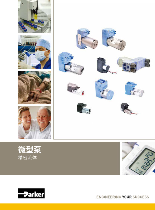
您与运动和控制技术领域的先行者合作,就是希望促进您的业务发展和全球的发展。
从微型电磁阀到高集成型自动化系统,我们的产品对于用于药物研发和病原体检测的救生医疗设备和科学仪器至关重要。
并且对于缩短上市时间和降低总体拥有成本也十分关键。
因此,请与派克合作,准备改变这一切吧!/precisionfluidics 1 603 595-1500目录页T2-05Helix124高效和紧凑型 13.5mm 宽泵 – 高达 800 mLPM高压泵 – 超过5.5 LPM 和高达100 PSI 的压力T2-0320高性能与尺寸比率泵 – 高达2.5 LPMLTC 系列76液体系列传送泵 – 高达 650 mLPMEZ 底座92振动隔离安装系统小型活塞泵(空气)微型泵(空气/气体)微型泵(液体)T2-0494超紧凑型、高效泵 – 高达 7.5LPMBTC-IIS 系列62应用广泛的多功能双头泵系列产品 – 高达 11 LPMBTC 系列52应用广泛的多功能泵系列产品 – 高达6 LPMLTC-IIS 系列84液体系列双头传送泵 – 高达1.5 LPMCTS 系列BTX-Connect 2836高性能紧凑型 20 mm 宽泵 – 高达 2.5 LPM多功能双头和单头泵系列,适合多种应用-高达10 LPMTTC 系列74紧凑、高效、低压泵 – 高达 6 LPMTTC-IIS 系列84紧凑、高效、低压双头泵 - 高达 11 LPM附件4Helix 微型高压泵高达100 PSI (6.9 bar)压力Parker Helix 是一款紧凑型高压泵,旨在实现小型即时临床护理仪器。
Helix 可在挑战性的高海拔环境和无法使用外部压缩空气的应用中实现高压操作。
Helix 泵可提供5.5 LPM 以上的流量和高达100 PSI (6.9 bar)的压力,为性能至关重要且空间有限的台式诊断设备提供了出色的解决方案。
• 集成了用于卸荷的X 阀,可实现高压重启• 内部飞轮可在高压下低速运行• 无油活塞• 简单的安装特性• 带有推入式接头的快速流体连接• 符合RoHS 指令和REACH 标准产品特性• 液上空气• 气动驱动•微流控芯片• 即时临床护理检验• 分子诊断• 核酸纯化•基因组学典型应用典型市场产品规格物理特性电子5微型隔Helix 微型高压泵典型流量曲线• 曲线展示了0.080"偏移泵的流量性能• 使用5.0 Vdc 控制输入时,泵将以大约4400 RPM 的转速和高达8.5 LPM的流量的状态运行,但不建议连续工作。
各种漆包铜线种类简介与要求

動繞線之作業。 應用範圍:電感器、音圈等。
12
FEAI 醯胺亞外被聚酯漆包銅線
耐溫等級:165度
絕緣說明:
FEAI為雙層絕緣,此種組合將PEW耐
磨特性提昇以獲得最佳特性,因外被
為自滑性AI兼具Nylon被覆之極佳繞線
性外,更有優於PEW+NY線種之耐溫
及機械特性。
特性:
(a)線材表面光滑,入線阻力極低,容
易操作,線圈容積小而結實。
(b)耐溫165度耐磨性絕佳,繞線不易 破
皮,特性遠優於一般155度 之PEW。
(C)具有極佳之繞線性,適合於高 速捲
繞或自動繞線。
13
應用範圍:繼電器、密封式線圈。
UEW 聚胺脂漆包銅線
一、易著性、高頻電氣性能優良。
10
LITZ 絞合漆包圓銅線
耐溫等級: 依選定之漆包線線材而訂。 絕緣說明: 依不同應用場合有多種不同絕緣線材 的選擇,且保有各漆包線材之優點。 特性: (a)可平衡磁通鏈與阻抗,使電流均 勻
地分佈於導體上,可降低因集 膚效 應所產生的高頻功率損失。 (b)具有良好的阻抗穩定性,其交、直 流阻抗比不隨波動。 應用範圍: 高頻線圈、寬度線圍、電磁爐線圈 、高頻電源供應器等。
特性 皮膜特別厚者 皮膜厚者 一般所採用的皮膜 皮膜薄者
15
漆包線之耐熱區分 等 Y A E B F H HC C 級
溫 度
90
105
12 0
13 0
15 5
18 0
20 0
22 0
16
三層絕緣線
特點: 一、減少線圈、變壓器50% 體積;70%重量。 二、省去層間絕緣、擋牆及 套管 等材料。 三、減少繞線時間,簡化流 程。
Perma STAR-CONTROL自动注脂器

中国长期以来畅销最佳的注油器产品是三和波达机电科技有限公司,不仅给机器滋润,还给企业带来无限的实惠,如机器的使用时间,及机器的维修时间延长,可畅通使用机器。
Perma STAR-CONTROL数码加脂器为电动机驱动型,驱动器可重复使用,油杯为一次性使用,更换油杯时要同时更换电池,出油时间由外部7-30VDC的电源控制。
深圳三和波达机电科技有限公司自2011年以来一直致力发展专业国际品牌进口供应。
在系统网络上与香港、新加坡仓库连网。
备有大量原装现货,100%香港原装进口,质量保证!价格实惠!自动注油器具有如下特性:1、主动受控制式润滑管理,大量节省设备维修成本。
2、可避免溢出污染或断油之烦恼。
3、可保持润滑面持续新油供给。
4、按需要随时可停可续。
5、独特设计,防爆安全,安装灵活,简便,不受方向、位置限制。
优势:一、人力:1.可減少人力工时。
2.可按设备所需定时定量给予油脂。
二、金钱:1.降低购油成本。
2.维修设备费用可减少,3.增加设备的妥善率。
4.减少设备维修时间。
5.增加产能。
6.加速设备自动化。
综合传统人工保养方式与自动注脂器的特点比较,我们可以非常直观的看出自动注脂器的使用给机器设备使用用户直接带来收益。
俗语说预防胜于治疗,而在全球化的竞争下设备的妥善率既是企业的竞争力,增加产值就是增加利润,所以日常设备的维修保养是非常重要的,而保养首重润滑,确实的润滑可降低设备耗损,减少维修费用可减低企业营运资金,进而有更多的资金投入企业运转,创造更大的利润,所以使用自动注脂器既可节流又可开源,更是一个企业进步的象征。
应用领域:一、化学工业:1.化工原料、产品制造业。
2.造纸业。
3.塑(橡)胶制品制造业。
4.玻璃纤维原料、制品制造业。
5.染料、顏料、色料、芳香料制造业。
6.石化原料制造业。
二、工业机械:1.工具机,2.工作母机。
3.食品机械、纺织机械、输送机械、化工机械等。
4.工业设备及制品制造业。
5.电工器材制造业。
帕尔萨自动注油器pulsarlube
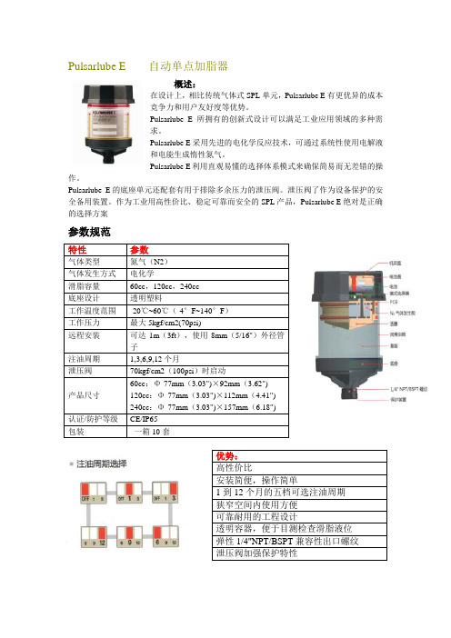
概述:在设计上,相比传统气体式SPL 单元,Pulsarlube E 有更优异的成本竞争力和用户友好度等优势。
Pulsarlube E 所拥有的创新式设计可以满足工业应用领域的多种需求。
Pulsarlube E 采用先进的电化学反应技术,可通过系统性使用电解液和电能生成惰性氮气。
Pulsarlube E 利用直观易懂的选择体系模式来确保简易而无差错的操作。
Pulsarlube E 的底座单元还配套有用于排除多余压力的泄压阀。
泄压阀了作为设备保护的安全备用装置。
作为工业用高性价比、稳定可靠而安全的SPL 产品,Pulsarlube E 绝对是正确的选择方案参数规范特性参数气体类型 氮气(N2) 气体发生方式 电化学滑脂容量 60cc ,120cc ,240cc 底座设计 透明塑料工作温度范围 -20℃~60℃(-4°F~140°F ) 工作压力 最大5kgf/cm2(70psi)远程安装 可达1m (3ft ),使用8mm (5/16")外径管子注油周期 1,3,6,9,12个月泄压阀 70kgf/cm2(100psi )时启动产品尺寸 60cc :Φ-77mm (3.03")×92mm (3.62") 120cc :Φ-77mm (3.03")×112mm (4.41") 240cc :Φ-77mm (3.03")×157mm (6.18") 认证/防护等级 CE/IP65 包装 一箱10套优势:高性价比安装简便,操作简单1到12个月的五档可选注油周期 狭窄空间内使用方便 可靠耐用的工程设计透明容器,便于目测检查滑脂液位 弹性1/4"NPT/BSPT 兼容性出口螺纹 泄压阀加强保护特性概述:Pulsarlube V单点加脂器的定向逻辑微处理芯片控制技术在产品的编程位置上实现一键式简体化操作。
自动注脂器
产品信息
珠海威润玛工业设备制造有限公司 ZHUHAI VMAXX EQUIPMENT MRO MANUFACTURING CO.,LTD
VMAXX
自动注脂器
产品简介
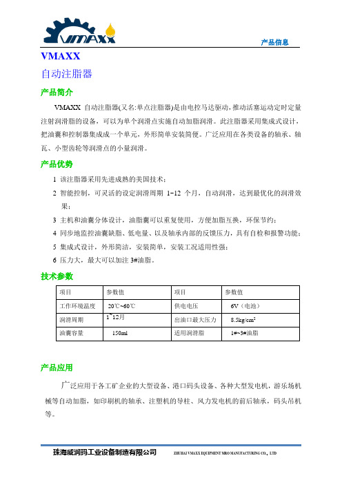
VMAXX 自动注脂器(又名:单点注脂器)是由电控马达驱动,推动活塞运动定时定量注射润滑脂的设备,可以为单个润滑点实施自动加脂润滑。
此注脂器采用集成式设计,把油囊和控制器集成成一个单元,外形简单安装简便。
广泛应用在各类设备的轴承、轴瓦、小型齿轮等润滑点的小量润滑。
产品优势
1 该注脂器采用先进成熟的美国技术;
2 智能控制,可灵活的设定润滑周期1~12个月,自动润滑,达到最优化的润滑效
果;
3 主机和油囊分体设计,油脂囊可以重复使用,方便加脂互换,环保节约;
4 同步地监控油囊缺脂、低电量、以及轴承内部的反馈压力,具有自检和报警功能;
5 集成式设计,外形简洁,安装简单,安装工况适用性强;
6 压力大,最大可以加注3#油脂。
技术参数
产品应用
广泛应用于各工矿企业的大型设备、港口码头设备、各种大型发电机,游乐场机械等自动加脂,如印刷机的轴承、注塑机的导柱、风力发电机的前后轴承,码头吊机等。
Pulsarlube EX 防爆自动注油器
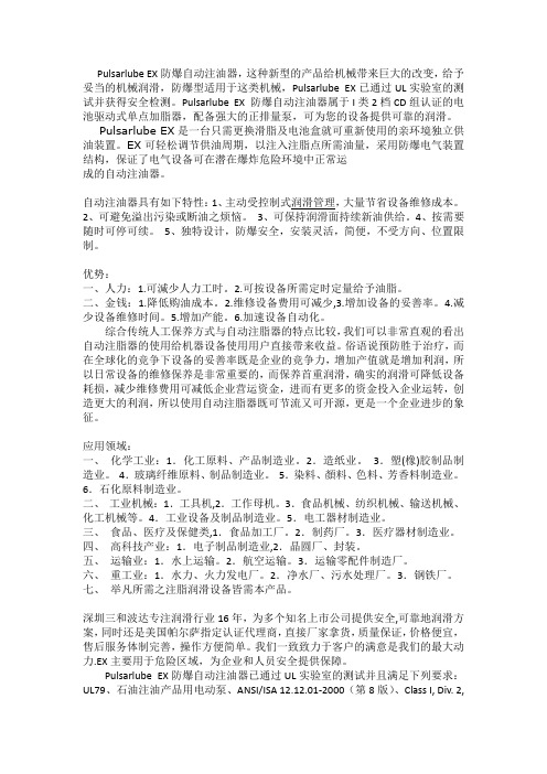
Pulsarlube EX防爆自动注油器,这种新型的产品给机械带来巨大的改变,给予妥当的机械润滑,防爆型适用于这类机械,Pulsarlube EX已通过UL实验室的测试并获得安全检测。
Pulsarlube EX 防爆自动注油器属于I类2档CD组认证的电池驱动式单点加脂器,配备强大的正排量泵,可为您的设备提供可靠的润滑。
Pulsarlube EX是一台只需更换滑脂及电池盒就可重新使用的亲环境独立供油装置。
EX可轻松调节供油周期,以注入注脂点所需油量,采用防爆电气装置结构,保证了电气设备可在潜在爆炸危险环境中正常运成的自动注油器。
自动注油器具有如下特性:1、主动受控制式润滑管理,大量节省设备维修成本。
2、可避免溢出污染或断油之烦恼。
3、可保持润滑面持续新油供给。
4、按需要随时可停可续。
5、独特设计,防爆安全,安装灵活,简便,不受方向、位置限制。
优势:一、人力:1.可減少人力工时。
2.可按设备所需定时定量给予油脂。
二、金钱:1.降低购油成本。
2.维修设备费用可减少,3.增加设备的妥善率。
4.减少设备维修时间。
5.增加产能。
6.加速设备自动化。
综合传统人工保养方式与自动注脂器的特点比较,我们可以非常直观的看出自动注脂器的使用给机器设备使用用户直接带来收益。
俗语说预防胜于治疗,而在全球化的竞争下设备的妥善率既是企业的竞争力,增加产值就是增加利润,所以日常设备的维修保养是非常重要的,而保养首重润滑,确实的润滑可降低设备耗损,减少维修费用可减低企业营运资金,进而有更多的资金投入企业运转,创造更大的利润,所以使用自动注脂器既可节流又可开源,更是一个企业进步的象征。
应用领域:一、化学工业:1.化工原料、产品制造业。
2.造纸业。
3.塑(橡)胶制品制造业。
4.玻璃纤维原料、制品制造业。
5.染料、顏料、色料、芳香料制造业。
6.石化原料制造业。
二、工业机械:1.工具机,2.工作母机。
3.食品机械、纺织机械、输送机械、化工机械等。
简明操作指南--Porline Promag 10--电磁流量计(10L)
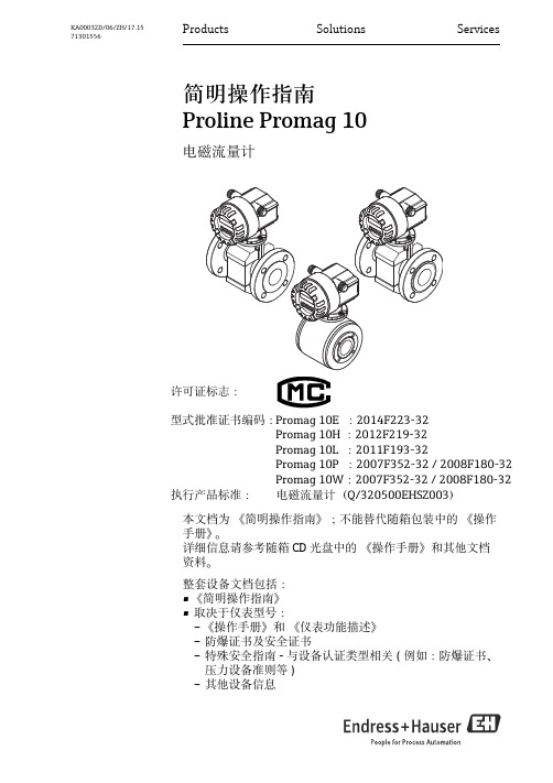
Proline Promag 10
2
Endress+Hauser
Proline Promag 10
目录
目录
1 安全指南 . . . . . . . . . . . . . . . . . . . . . . . . . . . . . . . . . . . . . . . . . . . . . . . . . . . . . . . . . . . . . . . . . 4
1.1 1.2 1.3 1.4 指定用途 . . . . . . . . . . . . . . . . . . . . . . . . . . . . . . . . . . . . . . . . . . . . . . . . . . . . . . . . . . . . . . . . . . . . . . . . . . . . . . . . . . . . . . . . . 安装、调试和操作 . . . . . . . . . . . . . . . . . . . . . . . . . . . . . . . . . . . . . . . . . . . . . . . . . . . . . . . . . . . . . . . . . . . . . . . . . . . . . . . . . 操作安全 . . . . . . . . . . . . . . . . . . . . . . . . . . . . . . . . . . . . . . . . . . . . . . . . . . . . . . . . . . . . . . . . . . . . . . . . . . . . . . . . . . . . . . . . . 安全图标 . . . . . . . . . . . . . . . . . . . . . . . . . . . . . . . . . . . . . . . . . . . . . . . . . . . . . . . . . . . . . . . . . . . . . . . . . . . . . . . . . . . . . . . . . 4 4 4 5
自动加脂器

帕尔萨M型 帕尔萨EX型 帕尔萨S型 帕尔萨C型 帕尔萨V型 帕尔萨MSP型 帕尔萨E型
帕尔萨M型
概述: 在设计上,创新型pulsarlube M确保润滑可靠性的同时还通过先进的计算机 控制系统节约降低润滑成本。 本产品由பைடு நூலகம்式进给泵、马达/齿轮组,以及微处理器组成,可在30kgf/c㎡ (425psi)的工作压力下工作。 通过远程安装功能,本产品成为难及场所/危险区域的理想选择。以下为 pulsarlube M无与伦比的优越性。 参数规范: 容量: 125cc,250cc 泵机类型: 立式自吸泵 注油周期: 半个月,1、2、3、6、12个月 工作压力: 平均30kgf/c㎡(425psi),最大60kgf/c㎡(850psi) 工作温度范围: -15℃~60℃(5℉-140℉),-40℃~60℃(-40℉140℉) 电池: 直流4.5V电池组(可更换) 安装螺纹尺寸: 3/8"PT 注油量: 20℃下每冲程0.34cc 保护等级: IP54 多点润滑: 可进行8点润滑,每个点6m(20ft) 产品认证: CE 包装: 一箱8套
帕尔萨C型
Pulsarlube C单点润滑器 【单点润滑器】来自美国的高科技产品-Pulsarlube C单点润滑器。 【单点润滑器】单点润滑器是在生产过程中延长轴承生命的一种装置。 【单点润滑器】 Pulsarlube C是电化学、自动化的单点润滑器新一代品种,它的设计能确保在工业领 域广泛应用上可精确、可预见、新鲜的供应润滑油 【单点润滑器】Pulsarlube C是在受压状态下,通过产生惰性氮气的控制反应,递送自身包含的(预包含 的)润滑油。 【单点润滑器】靠金属/酸性反应,填充不同于传统气体的润滑器用可燃氢(氢气)。 【单点润滑器】Pulsarlube C使用了由微处理器控制的惰性氮气,这是广泛用于车辆的类似安全气囊的 技术。
帕尔萨自动注油器
帕尔萨自动注油器来自美国的高科技产品-帕尔萨自动注油器(Pulsarlube C电化学自动单点润滑器)。
单点润滑器是在生产过程中延长轴承生命的一种装置。
Pulsarlube C是电化学、自动化的单点润滑器新一代品种,它的设计能确保在工业领域广泛应用上可精确、可预见、新鲜的供应润滑油。
Pulsarlube C是在受压状态下,通过产生惰性氮气的控制反应,递送自身包含的(预包含的)润滑油。
靠金属/酸性反应,填充不同于传统气体的润滑器用可燃氢(氢气)。
Pulsarlube C使用了由微处理器控制的惰性氮气,这是广泛用于车辆的类似安全气囊的技术。
特点:内置微处理器精确/可靠的分配程控的逻辑电路操作简便可沉入水中高性能润滑器4级可变分配率说明:操作温度:- 4华氏度-140华氏度最大工作压力: 4.8atm滑脂容量:125cc/ 250 cc 防爆证明: Ex ia IIB T45种标准油脂( 多用途/ 耐用/ 高速/ 食品级/ 高温)应用:一般应用包括○危险或不宜进入的地方○受污染时○润滑器保养人员不够时敬请关注石家庄北方大正Pulsarlube和A TS(A TS Electro-Lube International Inc.)的系列产品1、Pulsarlube-美国自动注油器①Pulsarlube MSP自动注脂器(MSP125 MSP250 MSP500)②Pulsarlube MS 自动润滑器(MS125 MS250 MS500)③Pulsarlube EX 自动润滑泵(EX125 EX250)④Pulsarlube C 单点润滑器(KLT100 KLT200)⑤Pulsarlube OL500自动注油器⑥帕尔萨自动注脂器-M (KLT125 KLT250)⑦电化学自动单点润滑器-Pulsarlube C (KLT100 KLT200)⑧帕尔萨自动注油器ML500 (Pulsarlube ML500)⑨V ariable自动注脂器(KLT200C)⑩KLT1500自动注油器[弹簧式] (Pulsarlube S)2、A TS(A TS Electro-Lube International Inc.)-加拿大自动注油器①Micro-Luber自动注油器(60ml)②Mini-Luber迷你润滑杯(125ml)③Budget-Luber自动注脂器(250ml)④Jumbo-Luber自动润滑泵(475ml)⑤MD125电子自动注油器(125ml)⑥MD250电子自动注油器(250ml)⑦MD500自动加油泵(500ml)⑧ULT125电子自动润滑器⑨ULT250电动注油器⑩ULT500电动润滑泵。
巴克尔(Parker)空气准备系统产品目录说明书

Pneumatic Air Preparation Systems Optional Port Block Kits• To change port sizes Port Block Kits are available, they are attached to any unit utilizing the connecting kit.• Allows assemblies to be removed from a hard pipedsystem.Modular ManifoldP3Y Series Manifolds provide up to 4 extra outlet ports. They may be assembled at any position in a combination e.g. before the lubricator to provide oil free take off or at theend of a combination to provide extra outlet ports.Port sizesInlet port Top Bottom Front and Back 3/4"1/8”1”1/4”1"1/8”1”1/4”G1AccessoriesMaterial specificationsBody Aluminium Weight0.65 kg (1.43 lb)Material specificationsBody Aluminium Weight0.7 kg (1.5 lb)Dimensions mm (inches)Pneumatic Air Preparation SystemsSolenoid OperatorsSolenoid Operators - CNOMO MaterialsTechnical data -Solenoid operators, coil combinationsPilot ValveBody:Polyamide Armature tube:BrassPlunger & core:Corrosion resistant Cr-Ni steel Seals:Fluorocarbon Screws:Stainless steelCoilEncapsulation material:Thermoplastic as standard Duroplast for M12 connectionTransientsInterrupting the current through the solenoid coil producesmomentary voltage peaks which, under unfavorable conditions, can amount to several hundred times the rated operating voltage. Normally, these transients do not cause problems, but to achieve the Maximum life of relays in the circuit (and particularly of transistors, thyristors and integrated circuits) it is desirable to provide protection by means of voltage-dependent resistors (varistors). All connectors/cable plugs EN175301-803 with LED’s include this type of circuit protection.Solenoid Coils with M12 ConnectionSolenoid Coils with DIN A or Industrial B Connectionabove part numbers for spares. The operators are supplied with mounting screws and interface ‘O’ rings. Coils and connectors must be ordered separately.22mm x 30mm 30mm x 30mm Part number Spare Base Solenoid Pilot Operator CNOMO NCNC Normal Operator with 22 x 30 standard coilNC Normal Operator with 30 x 30 standard coil Working pressure 0 to 10 bar 0 to 10 bar Ambient temperature -10°C to 60°C *-10°C to 60°C *Power (DC) 4.8W 2.7W Power (AC)8.5VA 4.9VA Voltage tolerance +/-10%+/-10%Duty cycle 100%100%Insulation class FFElectric connection B Industrial DIN 43650A Protection IP65IP65Approval UL/CSAWorking mediaAll neutral media such as compressed air* Limited to 50°C if use with 100% duty cyclePneumatic Air Preparation SystemsSolenoid Nuts, Connectors & CablesSolenoid Connectors / Cable Plugs EN175301-803Part number 22mm Form B Part number 30mm Form A Solenoid coil dimensions mm (inches)Cable plug dimensions mm (inches)Electrical schematics22mm Form B industrial cable plugs22 x 30mm30 x 30mm30mm DIN 43650A cable plugs。
Parker Hannifin 公司胶带和气垫类型蓄力器目录说明书

Accumulator Sizing For:•Shock Suppression •Thermal Expansion •Pulsation Dampening •Auxiliary Power SourceSizing and Selection•Piston Accumulators •Bladder Accumulators •KleenVentSizing and Selection SoftwareParker offers leading edge application assistance, in the form of the Accumulator Sizing and Selection Software (see page 16).For manual sizing calculations, see below and on the following pages.For further engineering assistance, contact Parker’s Accumulator T echnical Support Group at (815) 636-4100.Where:P 2=Maximum operating pressure in PSIA P 3=Minimum operating pressure in PSIA P 1=Pre-charge pressure required in PSIAV W =Volume of fluid collected or discharged by accumulator, In 3V 1=Required Accumulator volume, In 3f = Nitrogen gas constant-charging of Accumulators (see charts on pages 134-135)n = Nitrogen gas constant-discharging of Accumulators (see charts on pages 134-135)Note:Gas Precharge usually 100 psi below minimum pressure for Piston Accumulators*.Gas precharge is 90% of minimum pressure for Bladder Accumulators .*90% where minimum system pressure is less than 1000 psi.Calculations for accumulator sizing take into consideration the charge and discharge rate of the accumulator.Auxiliary Power SourceAccumulator Sizing for:•Shock Suppression •Thermal Expansion •Pulsation Dampening •Auxiliary Power SourceV =1V wP P 311f /0.95 1 –P P 321n/Hydraulic line shock suppressionThermal ExpansionWhere:α=Coefficient of Linear Expansion of Pipe Material per °F β=Coefficient of Cubical Expansion of Fluid per °F n =Discharge Coefficient (see charts on pages 134-135)P 1=PrechargeP 2=Minimum System Pressure @ T 1 (PSIA)P 3=Maximum System Pressure @ T 2 (PSIA)V 1=Accumulator SizeV a =Fluid Volume Subject to Thermal Expansion T 1=Initial Temperature (Lower Temp °Kelvin)T 2=Final Temperature (Higher Temp °Kelvin)Where:W =weight of fluid (lbs)V =fluid velocity (ft/sec)n = Discharge coefficient (see charts on pages 134-135)P 2=system pressure P m =Shock pressureV 1=accumulator size required P 1=pre-charge pressure G =force of gravity Q=flow rate in GPM()()V 1=−−−V T T P P P P a nn2121231131βαV =1P P 211n /2 (g) (P )2P P m 2(n-1)n/(12W) (V ) (n-1)2+ (Q1.155)*– 1Coefficient of Linear Expansion of Pipe Material per °F Steel: 6.33 x 10⁻⁶Cast Iron: 6.55 x 10⁻⁶Aluminum:10 x 10-6Coefficient of Cubical Expansion of Fluid per °F Water: 1.15 x 10⁻⁴Oil:4.60 x 10⁻⁴Piston pump pulsation dampeningWhere:K =Pump output coefficient n = Coefficient of discharge (see charts on pages 134-135)P 1=Nitrogen gas pre-charge P 2=System operating pressureP 3=Maximum allowable shock pressure A =Piston area L =Piston strokeV 1=Accumulator size requiredExisting accumulator output used in an auxiliary power source application.Calculations for accumulator sizing takes into consideration the charge and discharge rate of the accumulator.Pump output coefficient is calculated depending on single acting or double acting pump:Simplex single .60Simplex double .25Duplex single .25Duplex double .15T riplex single .13T riplex double .06Quadruplex single .10Quadruplex double .06Quintiplex single .06Quintiplex double.02V =1ALK P P 211 –P P 231n /1n/Where:P 2=Maximum operating pressure in PSIA P 3=Minimum operating pressure in PSIA P 1=Pre-charge pressure required in PSIAV W =Volume of fluid collected or discharged by accumulator, In 3V 1=Required Accumulator volume, In 3f = Nitrogen gas constant-charging of Accumulators (see charts on pages 134-135)n = Nitrogen gas constant-discharging of Accumulators (see charts on pages 134-135)Note:Gas Precharge usually 100 psi below minimum pressure for Piston Accumulators .Gas precharge is 90% of minimum pressure for Bladder Accumulators .V =w P P 311f /1 –P P 321n /0.95V 1Temperature VariationT emperature variation can seriously affect the precharge pressure of an accumulator. As the temperature in-creases, the precharge pressure increases; conversely, decreasing temperature will decrease the precharge pressure. In order to assure the accuracy of your accumulator precharge pressure, you need to factor in the temperature variation. The temperature variation factor is determined by the temperature encountered during precharge versus the operating temperature expected in the system.Temperature During PrechargeLet’s assume the temperature during precharge is 70°F, the expected operating temperature is 130°F, and your desired precharge is 1000 psi. Find the charging temperature of 70°F in the top horizontal row. Next, find the operating temperature of 130°F in the left hand, vertical column. Extend lines from each value until they intersect to find the temperature variation factor; in this case, 0.90. Multiply the desired precharge of 1000 psi by the temperature variation factor of 0.90 to obtain the actual precharge pressure required – 900 psi.Selection Chart for Charge Coefficient “f”& Discharge Coefficient “n” Chart No. 10 - 8 Seconds9 - 30 SecondsPressure (PSI)Pressure (PSI)61 - 120 Seconds31 - 60 Seconds Pressure (PSI)Pressure (PSI)n & fn & fSelection Chart for Charge Coefficient “f”& Discharge Coefficient “n” Chart No. 1Instructions for selection ofCharge Coefficient “f” & Discharge Coefficient “n”1.Determine Average System Pressure.2.Determine the time required in seconds to charge the accumulator with fluid.3.Determine the time in seconds to discharge the oil from the accumulator.4.Select the graph which corresponds to the time (seconds) required to charge (discharge) the accumulator with fluid .5.Select the curve on the graph which corresponds to the gas operating temperature. (If gas tempera-ture under operating conditions is not known,assume 100°F .)6.To use the graph, locate the average system pressure along the bottom portion of the graph.Move vertically along this column until you inter-sect the line corresponding to the gas temperature.Then move horizontally along this line, read the charge coefficient “f” on the left side of the graph.“f” = Charge Coefficient.7.Repeat for the discharge coefficient “n” starting with Step #4.“n” = Discharge Coefficient.121-500 Seconds501-900 SecondsPressure (PSI)Pressure (PSI)n & f*Safety Note:In any accumulator circuit, a means should be available Array of automatically unloading the accumulator when the machine is shut down. Such a valve could be located at this point in the circuit.Control of Usable VolumeThe usable volume of an accumulator should be discharged at a controlled rate. If an accumulator is required to maintain system pressure, this controlled rate is automatically achieved by the leakage fluid it has to replace. However, an accumulator which is used to develop a pressurized flow can discharge its usable volume too rapidly as a downstream directional valve is shifted. For this reason, accumulators in this application are often equipped with a flow control and bypass check at their inlet-outlet port.Pump Unloading inAccumulator CircuitsT o keep a pump/electric motor fully unloaded until it is required to re-charge an accumulator, an electric pressure switch can be used.In the circuit illustrated, a pressure switch senses accumulator pressure sending and cutting-out electrical signals at various pressure levels. The electrical signals are transmitted to a normally-open, solenoid operated 2-way valve which vents and de-vents a pilot operated relief valve. When the accumulator is being charged, the pressure switch sends an electrical signal to the 2-way valve solenoid. With the accumulator charged, the pressure switch cuts out the signal, venting the relief valve and unloading pump/electric motor. The setting of the pressure switch determines the pressure range within which a pump/electric motor works.Using a pressure switch to vent a relief valve results in a pump/electric motor being fully unloaded when system conditions dictate.In the circuit illustrated, an unloading valve is used to dump a flow back to tank once an accumulator is charged to the unloading valve setting.Once the valve closes, pump/electric motor must there-fore generate power to recharge the accumulator to theunloading valve setting.Differential Unloading Relief Valve Instead of using a pressure switch and solenoid valveto vent a relief valve while an accumulator is charged, one hydraulic component can be used — a differential unloading relief valve.A differential unloading relief valve is specifically designed for use with accumulators. As its name implies, the valve unloads a pump/electric motor over a differential pressure range.A differential unloading relief valve consists of a pilot operated relief valve, check valve, and differential piston in one valve body. The valve body includes pump, tank, and accumulator passages.Maintaining PressureAccumulators are used to maintain pressure. This can be required in one leg of a circuit while pump/electric motor is delivering flow to another portion of the system.In the circuit illustrated, two clamp cylinders are re-quired to hold a part in place. As the directional valves are shifted, both cylinders extend the clamp at the pump’s compensator setting. During this time, the accumulator is charged to the setting also.System demands require that cylinder B maintain pressure while cylinder A retracts. As directional valve A is shifted, pressure at the pump, as well as in line A, drops quite low. Pressure at cylinder B is maintained because the accumulator has stored sufficient fluid under pressure to make up for any leakage in line B. Accumulators not only maintain pressure by compen-sating for pressure loss due to leakage, but they also compensate for pressure increase due to thermal fluid expansion or external mechanical forces acting on a cylinder.In the illustrated circuit, assume that the cylinder is operating near a furnace where ambient temperatures are quite high. This causes the fluid to expand. With an accumulator in the circuit, the excess volume is taken up, keeping the pressure relatively constant. Without an accumulator, pressure in the line would rise uncontrolla-bly and may cause a component housing, fitting, or conductor to crack.The same situation can also occur if an external mechanical force acts to retract the cylinder. Assume now that the cylinder is clamping a curing press. As curing occurs, heat within the press causes it to expand resulting in a force acting to retract the piston rod. The accumulator once again absorbs the additional volume, maintaining the pressure at a relatively constant level. *Safety Note:In any accumulator circuit, a means should be available for automatically unloading the accumulator when the machine is shut down. Such a valve could be located at this point in the circuit.RetractDeveloping FlowSince charged accumulators are a source of hydraulic Array potential energy, stored energy of an accumulator canbe used to develop system flow when system demandis greater than pump delivery. For instance, if amachine is designed to cycle infrequently, a smalldisplacement pump can be used to fill an accumulatorover a period of time. When the moment arrives for themachine to operate, a directional valve is shifteddownstream, and the accumulator delivers the requiredpressurized flow to an actuator.Using an accumulator in combination with a smallpump in this manner conserves peak horsepower. Forinstead of using a large pump/electric motor togenerate a large horsepower all at once, the work canbe evenly spread over a time period with a small pump/electric motor.Absorbing ShockHydro-pneumatic accumulators are sometimes used toabsorb system shock even though in this applicationthey are difficult to properly design into a system.Shock in a hydraulic system may be developed fromthe inertia of a load attached to a cylinder or motor. Or,it may be caused by fluid inertia when system flow issuddenly blocked or changed direction as a directionalvalve is shifted quickly. An accumulator in the circuit willabsorb some of the shock and not allow it to be trans-mitted fully throughout the system.Shock may also occur in a hydraulic system due toexternal mechanical forces. In the circuit illustrated, theload attached to the cylinder has a tendency to bouncecausing the rod to be pushed in and shock generated.An accumulator positioned in the cylinder line can helpreduce the shock effects.*Safety Note:In any accumulator circuit, a means should be availablefor automatically unloading the accumulator when themachine is shut down. Such a valve could be located atthis point in the circuit.Developing System FlowPiston and Bladder TypePlease fill out and fax to 815-636-4113.For assistance, call 815-636-4100.CUSTOMER:ADDRESS:CONTACT:PHONE:FAX:EMAIL:Quantity/Release:___________________________Quantity (Annual):___________________________Type (Piston or Bladder):_____________________Bore Size (piston only):______________________Capacity:__________________________________Working Pressure/Design Factor._______________Seal Type/Compound:________________________Hydraulic Port:______________________________Gas Port:__________________________________Operating Temperature Range:_________________System Fluid:______________________________Gas Valve:_________________________________Precharge:_________________________________Water Service?____________________________Plating/Coating:____________________________Material Type:______________________________Paint:____________________________________Switches:_________________________________Certification:_______________________________Special Test?_______________________________Special Label?_____________________________Customer Drawing Included?_________________Customer Part #___________________________Envelope Restrictions:_______________________Contact InformationApplication Description/CommentsCustomer RequirementsFORM-0117, Rev. 1Application Data SheetPiston and Bladder Type Notes。
SPA XTREME-X火灾抑制系统安装指南说明书

1 SPA DESIGN Fire Suppression manua lT hank you for purchasing one of our latest range of systems Homologated to the latest FIA standard 8865-2015. This manual covers the following system XTREME-XIt is important that you read the following instructions carefully before attemptingtoinstall your fire suppression systems.T he performance of these systems could be affected if they are in any way modified or tampered with and will void its homologation. Please ensure you only use genuine SPA parts should any part need replacing.Should you require assistance with this please call +44(0)1543 434580 or ********************.uk Pages2-345-67-1113-141215-16Index Contents System fitting instructions Electrical installation Engine bay /cockpit nozzlelocationConnecting Copper pipeSystem picturesBottle dimensionsData sheetsInstallation Notes17 182SYSTEM1 X SPA-F-500-APS-B BOTTLE ONLY1 X SP387 BOTTLE PLINTH2 X SP386 BOLTED STRAPS1 X SP287 EXTENSION PIPE2 X SP280 10MM COPPER PIPE PER METER1 X SP281 DEFLECTOR NOZZLE1 X SP282 BULKHEAD CONNECTOR ¼ BSP-M201 X SP283 10mm ¼ BSP COMPRESSION FITTING1 X SPA-E X T-APS-B BOTTLE ONLY1 X SP388 BOTTLE PLINTH2 X S P386 BOLTED STRAPS1 X SP281 DEFLECTOR NOZZLE1 X SP288 ½ METER 12.7MM COPPER PIPE1 X SP282 BULKHEAD CONNECTOR ¼ BSP-M201 X SP287 EXTENSION PIPE1 X SP289 12.7MM ¼ BSP COMPRESSION FITTINGELECTRICAL KIT3 X SP005H HIRSCHMAN PLUG & LEADS1 X SP277 NEW FIA STANDARD POWER PACK HIRSCHMAN TYPE 1 x SP011 INTERNAL FIRE BUTTON1 X SP012 EXTERNAL FIRE BUTTON1 X SP017 E LOCATION STICKER LARGE1 X SP129 E LOCATION STICKER SMALLSYSTEM FITTING INSTRUCTIONSU npack all parts and check co mponents against check list on pages 2 & 3.Mount the engine bay system in or around the passenger footwell ideally in a transverse position page 7-11Mount the cockpit system ideally as detailed on page s7-11 behind driver or passenger seat.The extinguisher label, detailing contents etc. should be visible, mount the plinth securely to the vehicle and secure the bottle with the straps provided.Mount the power pack in a clearly visible position.Switch with Shroud (SP011) to be fitted in the cockpit within easy reach of both driver and co-driver when sitting in normal driving position and wearing fastened seatbelts.External switch (SP012) to be fitted to outside of vehicle, close to master switch (to activate by marshals when required).Electrical system to be wired as shown on page 6.TEST POSITIONWith the switch in the test position, the power pack is not armed and draws no current until either the internal switch (SP011) or external switch (SP012) is pressed.To initiate the test routine, press either internal or external switch .Test all goodIf all the tests are good, the n the amber test lamp will light for 6 seconds and then go off. This means that the system has not been operated and the Co2 canister is still charged and all wiring continuity is good. Test failedIf one of the tests fails, the amber light will flash the fault indication for 12 seconds and go off.Fault IndicationIf the amber test lamp flashes one pulse at a time, this is error 1 = low batteryIf the amber test lamp flashes two pulses at a time, this is error 2 = Continuity Ohms too highIf there is a short in the wiring or if the firing button is not released, then the amber light will change from good (no flashing) to error (flashing error 3) after 6 seconds.If the amber test lamp flashes three pulses at a time , this is error 3 = short circuitWarning error 3 will continue to flash until the fault is removed – DO NOT switch system to armed if error 3 is flashing as this may operate the fire suppression systems, you must locate the fault in the wiring harness or switches.If no lights come on when you press the button, then there is no continuity. This can be due to a loom fault, a switch fault, an expended firing head, incorrect wiring, firing head not plugged in or a flatbattery(check the battery by disconnecting the loom and momentarily switching to Armed position). no A RMED POS I TION With the switch in armed position, the power pack is providing full battery power to the output socket. If power pack switch and the battery volts are good, then the Red Armed LED will flash constantly. The Red LED only uses a very small amount of power; the battery should be replaced every 6 Test positionSystem armed positionPower PackHirschman External Firing Button Internal Firing Button Brown Blue Blue Brown BrownBlue Hirschman HirschmanJoinJoin Black1. INSTALLATION DU SYSTEME D’EXTINCTION / FIRE EXTINGUISHER SYSTEM INSTALLATION101. INSTALLATION DANS L’HABITACLE / COCKPIT INSTALLATIONa) Emplacement et orientation du corps Location and orientation of body Horizontally mounted behind passenger or driver seat or in front of driver or passenger seat.b) Emplacement et orientation des buses Location and orientation of nozzles Located between driver and passenger seat or towards the front centre of car.c) Précaution à prendre lors de l’installation du systèmeSpecial care to take with the installation of the systemE1-1) Installation dans l’habitacle (emplacement et orientation du corps) Cockpit installation (location and orientation of body)E1-2) Installation dans l’habitacle (emplacement et orientation desbuses)Cockpit installation (location and orientation of nozzles)102. INSTALLATION DANS LE MOTEUR / ENGINE INSTALLATIONa) Emplacement et orientation du corpsLocation and orientation of bodyHorizontally mounted b) Emplacement et orientation des busesLocation and orientation of nozzlesMount off bulk head, central to engine c) Précaution à prendre lors de l’installation du systèmeSpecial care to take with the installation of the systemE2-1) Installation dans le moteur (emplacement et orientation ducorps)Engine installation (location and orientation of body) E2-2) Installation dans le moteur (emplacement et orientation des buses) Engine installation (location and orientation of nozzles)ENGINE NOZZLE LOCATIONlocationBOTTLE LOCATION ENGINE Ideally m ount bottle in passenger footwell areaDEFLECTOR NOZZLE ORIENTATION ENGINE BAYNozzle locationIdeally m ount cockpit bottle either behind driver seat or passenger seatENG INE BAY NOZZLE CONNECTIONSThe engine bay Nozzle comes preassembled.1.Measure length of pipe required, cut to size using pipe cutter or hacksaw, deburr pipe.2.Push one end of pipe into 10mm fitting on bottle.3.Make 21mm hole in bulkhead.4.Insert bulkhead Fitting into hole from engine bay side5.Keep Deflector nozzle in position as shown on page 86.Turn M20 nut onto bulkhead Fitting until tight against bulkhead7.Screw ¼ BSP compression fitting into bulkhead connector until tight8.Place Compression nut and then olive onto 10mm pipe9.Insert pipe into compression fitting and tighten using two spannersCONNECTING COPPER PIPE – COMPRESSION FITTINGSOnce the pipes have been cut square – make sure all components are clean; you can use steel wool for this.Place the first nut over one of the sections of pipe.Next, place the olive over the pipe and push it along a little. Some olives have a right and wrong way round. If this is the case, they will have a different size chamfer on each side.The longest one goes against the middle of the joint.Place the fitting over the pipe and push it home. Line up the nut and hand-tighten.Using two spanners, hold the body of the fitting still with one, whilst tightening the nut with the other. It is important to tighten this nut by the right amount. If it is not fully tightened, the joint could leak.If the nut is over tightened, the olive and pipe can become distorted and the connection will leak. As a guide, the nut will usually require one complete revolution in addition to the hand-tightening. As the spanner is turned, you will feel some obvious resistance as the olive is pushed against the pipe. At this point, it will only need a little additional tightening to become watertight.This routine is to be applied to all compression fittings where pipework is connected.SYSTEM IMAGES COCKPIT SYSTEMENGINE SYSTEMS11417Data sheetsEXTREMEComposition Dodecafluoro-2-methylpentan-3-one,(CF3CF2C(O)CF(CF3)2)Ozone depletion NoneOperating temperature -40 to + 85 CFreeze point -108 CCritical temperature 168.7 CPhysiological properties no observed adverse effect level and lowest observed adverse effect level for cardiac sensitization (halocarbons) and oxygen depletion (Inert gas)F500Appearance Amber liquidOdour MildMelting Point -3°C (Freeze protected -15 C)Boiling Point 118°CSolubility in Water Complete at 20°CSpecific Gravity 0.990 g/ccpH Value 6.9 - 7.1 pHVapour Pressure (Air=1) 2,666 Pa @ 25°CFlash Point N/AFlammability Non-flammable liquidAuto-Ignition Temperature N/AExplosion Limits (lower/upper) Non-explosiveChemical Stability StableHazardous Decomposition Products None identifiedHazardous Polymerization Will not occurNozzle installation, install the bulkhead fitting as shownon page 11, apply a small amount of Loctite 243 orequivalent threadlocking medium strength adhesive toprevent vibration Fig 4.Now rotate the nozzle into the correct position asshown on page 8 or 9 and allow threadlocking adhesiveto cure.fig 1fig 2。
帕尔萨KLT数码加脂器介绍

频繁发生高差压的地方
特性
可重复利用,显示屏显示更方便
可多点使用,注油精度高
显示方便
显示停止喷油日期,便于供油管理 显示电池容量状态,准确告知更换时间 工作压力(20kgf/cm2)高,可适用于远距离安装
联系我们
敬请关注石家庄北方大正Pulsarlube和ATS(ATS Electro-Lube International Inc.)的系列产品 1、Pulsarlube-美国自动注油器 1 Pulsarlube MSP自动注脂器 (MSP125 MSP250 MSP500) 2 Pulsarlube MS 自动润滑器 (MS125 MS250 MS500) 3 Pulsarlube EX 自动润滑泵 (EX125 EX250) 4 Pulsarlube C 单点润滑器 (KLT100 KLT200) 5 Pulsarlube OL500自动注油器 6 帕尔萨自动注脂器-M (KLT125 KLT250) 7 pulsarlube\PULSARLUBE数码加脂器 8 pulsarlube\PULSARLUBE数码加脂器 9 Variable自动注脂器(KLT500 KLT1000) 10 KLT1500自动注油器[弹簧式] (Pulsarlube S)
帕尔萨KLT数码加脂器
目录
帕尔萨数码加脂器
KLT数码加脂器
M自动注油器
自动注脂器
1、产品尺寸 125cc:φ91×183( H)mm;250cc:φ91 ×210(H)mm 2、滑脂容量 125cc,250cc 3、电池盒 DC 4.5V(更换使用) 4、使用温度条件 -15℃~60℃ 5、帕尔萨KLT数 码加脂器工作压力 20Kgf/cm2 6、注油周期 1、 2、3、6、12个月 及15日(H)
REXA X2 XPAC系列调节型电液执行机构操作及维护保养规程
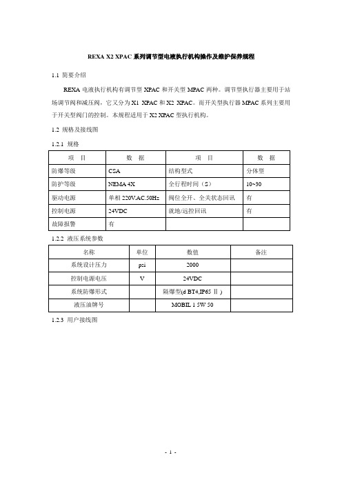
REXA X2 XPAC系列调节型电液执行机构操作及维护保养规程1.1简要介绍REXA电液执行机构有调节型XPAC和开关型MPAC两种。
调节型执行器主要用于站场调节阀和减压阀,它又分为X1 XPAC和X2 XPAC。
而开关型执行器MPAC系列主要用于开关型阀门的控制。
本规程适用于X2 XPAC型执行机构。
1.2规格及接线图1.2.1规格1.2.2液压系统参数1.2.3用户接线图图2 X2 XPAC执行器用户接线图1.3电气控制箱简要说明1.3.1X2 XPAC执行器控制箱采用一个真空荧光电视屏作为显示屏;操作按钮为5个,即“AUTO”、“MANUAL”、“ENTER”、“UP”、“DOWN”,利用这五个按钮组合实现执行器各种功能。
参见图5。
图5 X2 XPAC控制箱按钮示意图1.4操作模式1.4.1中控室远程控制:同时按下“AUTO”按钮和“ENTER”按钮;1.4.2就地电动开关阀门:同时按下“MANUAL”按钮和“ENTER”按钮;1.4.3就地修改参数:同时按下“AUTO”按钮和“MANUAL”按钮超过5s;1.4.4就地手动操作阀门:通过手轮进行操作。
1.5操作步骤1.5.1X2 XPAC执行器就地电动开关阀门1.5.1.1开阀:同时按下控制箱上“MANUAL”按钮和“ENTER”按钮并释放,将执行器切换到就地状态,然后按下“ENTER”按钮就会使显示屏上的“=”闪烁,此时按住“UP”按钮进行开阀。
通过显示屏可观察阀门开度,“Position=100.0%”表示阀门全开到位。
如需中途停止,释放“UP”按钮即可。
1.5.1.2关阀:同时按下控制箱上“MANUAL”按钮和“ENTER”按钮并释放,将执行器切换到就地状态,然后按下“ENTER”按钮就会使显示屏上的“=”闪烁,此时按住“DOWN”按钮进行关阀。
通过显示屏可观察阀门开度,“Position=0.0%”表示阀门全关到位。
如需中途停止,释放“DOWN”按钮即可。
- 1、下载文档前请自行甄别文档内容的完整性,平台不提供额外的编辑、内容补充、找答案等附加服务。
- 2、"仅部分预览"的文档,不可在线预览部分如存在完整性等问题,可反馈申请退款(可完整预览的文档不适用该条件!)。
- 3、如文档侵犯您的权益,请联系客服反馈,我们会尽快为您处理(人工客服工作时间:9:00-18:30)。
帕尔萨EX防爆型自动注脂器
产品简介
帕尔萨EX防爆型自动注脂器是来自美国的高科技产品。
它是一台只需要更换滑脂及电池盒就可重新使用的亲环境独立供油装置。
如同M系列,EX可轻松调节供油周期,以注入注脂点所需油量,采用防暴电气装置结构,保证了电气设备可在潜在爆炸危险环境中正常运行,防止非正常条件下引燃周围爆炸性气体,气电路及元件均基于节能概念制成的自动注油器。
产品引用标准:
§IEC 60079-15:爆炸性气体环境用电设备
§IEC 60529:外壳防护等级
§EN 50021/1999:潜在爆炸性环境用电气设备
§UL 79:石油产品输送机系统用动力泵
§ANSI/ISA-12.12.01-2000:Nonincendive electrical
Equipment for use in classⅠandⅡ,Divisions 1 and 2 hazardous locations
产品规格:
使用温度范围-15℃~16℃
最大自动压力15Kgf/cm2(200psl)
安装规格3/8"PT
远距离安装小于3m
用途独立自动注油器
注油周期1/2(H),1,2,3,6,12个月
容量125cc/250cc
警告:
(1)即使在危险区域停电或安装区域不受可燃性气体及蒸汽影响,也不要拆卸电池。
(2)切勿安装在发生强烈振动或撞击的地方。
(3)不要使用备用电池
(4)避开直射光线
相关产品
1、Pulsarlube-美国自动注油器
①Pulsarlube MSP自动注脂器(MSP125 MSP250 MSP500)
②Pulsarlube MS 自动润滑器(MS125 MS250 MS500)
③Pulsarlube EX 自动润滑泵(EX125 EX250)
④Pulsarlube C 单点润滑器(KLT100 KLT200)
⑤Pulsarlube OL500自动注油器
⑥帕尔萨自动注脂器-M (KLT125 KLT250)
⑦电化学自动单点润滑器-Pulsarlube C (KLT100 KLT200)
⑧帕尔萨自动注油器ML500 (Pulsarlube ML500)
⑨Variable自动注脂器(KLT500 KLT1000)
⑩KLT1500自动注油器[弹簧式] (Pulsarlube S)
2、A TS(ATS Electro-Lube International Inc.)-加拿大自动注油器
①Micro-Luber自动注油器(60ml)
②Mini-Luber迷你润滑杯(125ml)
③Budget-Luber自动注脂器(250ml)
④Jumbo-Luber自动润滑泵(475ml)
⑤MD125电子自动注油器(125ml)
⑥MD250电子自动注油器(250ml)
⑦MD500自动加油泵(500ml)
⑧ULT125电子自动润滑器
⑨ULT250电动注油器
⑩ULT500电动润滑泵。
