罗克韦尔集成运动控制讲义6
罗克韦尔--PPT教材
2012-7-28
HUST 罗克韦尔实验室
3
PLC 5 series
主要包括 PLC5/11 PLC5/20 PLC5/30 PLC5/40 PLC5/40L PLC5/60 PLC5/80
2012-7-28
HUST 罗克韦尔实验室
4
软件RSLinx 介绍
RSLinx是在Microsoft WinNT、Win95以及Win98操作系统下建立所有通信 方案的工具。它为A-B的可编程控制器与各种Rockwell Software及A-B应用软 件,如RSLogix5/500、RSView32等然间之间建立通信联系。 启动RSLinx后,应用程序窗口包括标题栏、菜单栏、工具栏、以子窗口 打开的应用程序工作区(RSWho、诊断等)以及一个状态栏,如下图所示。
到此,对实验中需用到的RSLinx已经介绍完。若要对RSLinx 有更多了解可借助Help或查看相关资料书.
2012-7-28 HUST 罗克韦尔实验室 8
软件RSLogix500 介绍
功能 : RSLogix500是针对SLC500和MicroLogix的以Windows操作系统为 基础的梯形图逻辑编程软件包。其运行环境是Microsoft indows95和 Windows NT,与Rockwell Software基于DOS的编程软件所创建的程序兼容. 1、自由组态梯形图编辑器集中应用逻辑,代替了写程序时严格的语法要 求 2、项目校验可建立错误信息列表,利于编程人员浏览和修改 3、拖放编辑功能可将数据表元素从一个文件移到另一个文件,将一个梯 级从一个子程序或项目文件中移到别处,或在一个项目文件内将指 令从一处移到另一处 4、搜索和替代可以快速改变地址或符号 5、项目树的界面可以访问项目包括所有的文件夹或文件 6、自定义数据监视器用于将分开的数据放在一起便于查看 7、有着与梯形逻辑编辑器一样简单的进行拖放操作的基于IEC 1131-3标 准的SFC和结构文本编辑器 8、梯形逻辑的可存取部分PC5库用于存放访问任意的PLC-5编程软件
罗克韦尔PLCSLC系统介绍PPT课件
第18页/共23页
1746-I/O系统
SLC-500系列PLC采用1746I/O
1746-I/O目录系统: 模拟量I/O模块 1746 – X X X X
型号类型: I- 电流, V- 电压 I/O点(通道)数 4,6,8,16 模块类型标识: I –输入, O-输出, R-热电阻, T-热电偶 N – 模拟量模块标识
从站) • 电池后备的RAM • 比SLC5/01更快的处第6理页/速共2度3页
SLC5/03
诊断指示灯
Keyswitch
DH485
• Peer Network • Programming
Serial Port
• DF1 Master /Slave • DH485 • ASCII
SLC 5/03 CPU
FLT BATT
ENET RS232
RUN REM PROG
Ethernet
• RJ45 Connector • Direct Twisted Pair
Serial Port
• DF1 Master /Slave • DH485 • ASCII
Ethernet R RS232
第9页/共23页
I/O能力:
RS-232C 根据应用的要求,可采用SLC-5/01,SLC-5/02, SLC-5/03,SLC-5/04,SLC-5/05系统.
第3页/共23页
SLC-500系列可编程序控制器
SLC500 产品处理器内存范围
5/05 5/04
范围
5/03
5/02
5/01
DH+
DH485
罗克韦尔自动化控制系统介绍课件

目录
• 罗克韦尔自动化控制系统概述 • 罗克韦尔自动化控制系统技术特点 • 罗克韦尔自动化控制系统应用案例 • 罗克韦尔自动化控制系统行业趋势与未来
发展 • 罗克韦尔自动化控制系统解决方案的价值
与优势
01
罗克韦尔自动化控制系统概述
公司背景与历史
成立于1903年,总部位于美国 密歇根州,是全球领先的工业 自动化解决方案提供商。
总结词
罗克韦尔自动化控制系统在智能仓储与物流系统中提供高效、准确的物资管理, 提升物流运作效率。
详细描述
该系统通过自动化识别、跟踪和调度等功能,实现了物资的高效管理、快速分拣 和准确配送,提高了物流运作效率和物资的利用率,降低了库存成本和运营风险 。
能源管理解决方案
总结词
罗克韦尔自动化控制系统为能源管理提供全面的解决方案, 帮助企业实现节能减排和可持续发展。
通过精确控制生产过程,自动化系统可以优化资源利用,降低能源消耗和生产成本 。
自动化系统能够实现快速响应和高效生产调度,缩短产品上市时间,提高企业竞争 力。
增强设备可靠性与安全性
01
罗克韦尔自动化控制系统具备高度可靠性和稳定性,能够保证 设备的长期稳定运行。
02
系统具备故障预警和诊断功能,可以及时发现并处理设备故障
,减少意外停机时间。
通过安全功能的集成,自动化系统能够降低安全风险,保障员
03
工和企业的安全。
优化企业运营管理与决策支持
罗克韦尔自动化控制系统提供全面的数据采集、分析和可视化功能,帮助 企业实现精细化运营管理。
系统能够整合企业内各部门的数据资源,促进信息共享和协同工作,提高 整体运营效率。
基于大数据分析和人工智能技术,自动化系统为企业提供科学决策支持, 助力企业战略发展。
罗克韦尔自动化运动控制基础知识说明书
课程安排第 1 天• 定义运动控制• 识别运动控制系统部件及功能 • 应用基本运动控制概念 • 识别数字伺服运动控制器的部件 •识别伺服驱动器的功能第 2 天• 识别交流和直流伺服电机的功能 • 识别反馈元件的功能 • 识别软件伺服环的功能 • 应用运动配置文件• 应用电子齿轮和凸轮运动曲线 •运动控制基础知识:集成练习课程编号:CCN130课程目的完成本课程后,您应该能够说明对所有罗克韦尔自动化运动控制系统通用的基本运动控制概念。
本课程旨在让您了解运动控制的概念、术语、功能及应用。
此外,您还将使用每节课讨论的概念和原理来了解运动控制应用项目如何工作。
本课程将帮助您建立牢固的必要基础,以便今后学习运动控制系统的维护和编程所需的技能。
本课程不针对运动控制系统设计或特定运动控制软件编程。
如果您要寻求这些方面的培训,应参加相关的罗克韦尔自动化培训课程,参加之前请确保您已符合这些课程的课前要求。
运动控制运动控制基础知识课程描述动力、控制与信息解决方案GMST10-PP247B-ZH-E版权所有 ©2010 罗克韦尔自动化有限公司。
保留所有权利。
美国印刷。
适合参加者为了工作而需要了解基本运动控制概念的人员,或者为了参加其他运动控制课程而需要学习这些概念以满足课前条件的人员应参加本课程。
课前要求参加本课程不需要满足任何特定课前要求。
但是, 以下几点将很有帮助:• 基本电学、电子学和计算机概念方面的背景 •控制器操作的基本知识技术要求罗克韦尔自动化将提供学员在课堂内使用的所有 技术。
学员在参加本课程时不必具备任何技术。
动手练习在整个课程期间,您将有机会通过各种涉及罗克韦尔自动化运动控制硬件的动手练习来实践所学的技能。
您还将有机会通过完成集成练习来组合和实践多项 关键技能。
学员资料为增强和促进您的学习体验,课程包中提供了以 下资料:•学员手册,其中包含主题列表和练习。
您将使用此手册来跟随讲课内容、记笔记和完成练习。
罗克韦尔自动化运动控制系统常见问题解答
罗克韦尔自动化罗克韦尔自动化运动控制系统运动控制系统常见问题解答1.什么是实轴什么是实轴??什么是虚轴什么是虚轴??答:实轴可以理解为实际存在的想要控制的电机,一台电机或者一台执行器(电动缸,直线电机)可以理解为一根实轴。
虚轴则是相对于实轴而言的,它是仅存在与控制器内部的一个数据对象,没有物理上的器件(电机或执行器)和它对应,虚轴通常在程序起到参考同步信号或标准位置信号来使用。
2.Kinetix 2000,6000,7000驱动器驱动器和和Ultra3000,5000等系列驱动器之间主要区别在哪里等系列驱动器之间主要区别在哪里??答:Kinetix系列和Ultra系列驱动器都是由罗克韦尔自动化有限公司生产的伺服驱动器产品,从运动控制功能上来说,都可以满足各类从简单到复杂的运动控制应用。
但两类产品又各有其特点和区别。
驱动器Kinetix 2000,6000 Ultra 3000,5000架构共直流母线设计,共用整流单元,安装空间小,接线数量少,更节能。
结合Logix5000软件可以很方便的开发出从中小型到大型设备的控制程序。
适用于大中型运动控制架构。
轴数较多情况下成本低于ultra系列。
7000系列由于功率较大,虽然同列入kinetix系列,单外观上仍为单体型。
传统单体型设计,每台驱动器具有各自的整流单元,接线数量多于kinetix系列,适用于中小型架构。
Ultra5000较特殊,具有支持高级语言C开发程序功能,客户可在驱动器内部编制并固化自己控制程序并自动运行。
称为智能化驱动器。
网络只支持Sercos网络。
将来会推出支持以太网CIP协议的驱动器支持Sercos,DeviceNet。
脱离网络可使用Ultraware预配置运行。
安全功能所有6000系列和部分2000系列已经支持安全扭矩关断功能。
不久将来,可以脱离安全继电器和控制器实现安全速度,安全门开关控制能安全功能。
尚不支持安全关断功能3.在Sercos架构的网络中架构的网络中,,每块PLC最多可以控制多少个伺服轴最多可以控制多少个伺服轴??答:对于罗克韦尔自动化不同产品线的PAC可以控制的伺服轴数量限制是不同的。
罗克韦尔PLC入门教材ppt课件

不可以修改
2) 用户存储器(RAM, EPROM, EEPROM)
分为: • 用户程序存储器- 存储用户程序 • 用户数据存储器- 存储运算数据
Rockwell Automation Internal
Rockwell Automation Internal
PLC控制系统的基本组成(7)
– 编程设备: 用于输入, 检查, 修改, 调试
用户程序. 在线监视PLC系统的工作状态
PC机+编程软件 专用编程器
编程器
– 电源模块: 将交流或直流电源转换成供PLC 系统工作的电源(通过机架的基板供电) 外挂式或机架内安装
ACIG基础培训课 (Francis.Duan) • PLC控制系统原理
• PLC控制系统的产生和定义 • PLC控制系统的组成 • PLC控制系统的工作原理 • PLC控制系统的编程
Rockwell Automation Internal
PLC控制系统的产生和定义(1) • PLC控制系统的产生:
2) 接收来自编程设备的用户程序和 数据
3) 对设备的状态和用户程序进行诊断 4) 运行用户程序 5) 实现与外部设备的通讯
一般用处理器的处理速度和I/O能力来说明
Rockwell Automation Internal
PLC控制系统的基本组成(3)
• 存储器: 1) 系统存储器 (ROM, Flash ROM)
Rockwell Automation Internal
PLC控制系统的基本组成(5)
– 输出模块: 用于向执行机构输出控制信号:
开关量输出模块: 直流信号: 24V DC, 48V DC 交流信号: 110V AC, 220V AC 触点信号: AC/DC
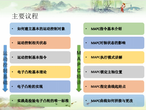
罗克韦尔自动化运动控制基础 + MAPC精讲
3、凸轮曲线是按增量执行的——注意启动凸轮时的轴位置
4、通过Scaling参数可以缩放凸轮曲线——实际项目中用得不多
5、MAPC已经IP了不一定是凸轮已经开始执行——还要看选定的Schedule类型
6、Master Lock Position是绝对位置!Pending模式下该值不生效 Master Lock Position为0时是增量位置——因为Lock的是主轴当前的绝对位置
Control Step=300 执行MSF
任何情况下如果伺服报警
进入等待允许使能状态
Control Step=999 等待报警复位 报警复位
Control Step=999 根据实际情况执行
MAFR、MASR 伺服没有报警
Control Step=0
Cmd_Reset
14
实践三、开始运动(点动、相对定位、绝对定位)
5
电子凸轮基本理论
✓ 电子凸轮(英文简称ECAM)是利用构造的凸轮曲线来模拟机械凸轮,以达到机 械凸轮系统相同的凸轮轴与主轴之间相对运动的软件系统
6
电子凸轮基本理论
✓ 论主轴与从轴的关系 —— 从轴跟随主轴,关系不断(.IP)跟随不断 —— 就算主轴报警了,从轴还是继续跟随的! —— 从轴还可以做“兼职”☺ MAPC+MAJ/MAM/MAG
8
电子凸轮的实现
▪ 从轴如何身兼多职?
MAPC
Merge = Disabled
MAJ
跟随的同时走点动
MAM
跟随的同时走定位 (一般叠加相对定位)
MAG
您可以有两个主轴☺
9
电子凸轮的实现
▪ 从轴要执行两个MAPC?怎么做到啊?
1、VAxis01跟随Vaxis_Master01走MAPC位置凸轮CAM(曲线Cam01a_P) 2、VAxis01跟随Vaxis_Master02走1:1的Gear(注意选择无离合模式) 3、 Vaxis_Master02跟随Vaxis_Master01走MAPC位置凸轮CAM(曲线Cam02a_P)
rockwell_讲义
PF4M
PVC 2"
微型断路器
马达保护开关
PVC 3" CSDJ PF4 接触器 NX70 CSDP PF40 PVC 6" 过载继电器
软启动器 PF40P Kinetix3 MicroLogix RSM系列 伺服电机 PVC 10" PF400/P
塑壳断路器
开关按钮指示灯
Copyright 2008 Rockwell Automation, Inc. China OEM Components.
Copyright 2008 Rockwell Automation, Inc. China OEM Components.
NX70 的设计
高性能系统的传统基板式设计
专用模块 I/O模块 8点模块-继电器输出 16点输入-DC24V,AC 110,AC 220 16点输出-TR(NPN),继电 器,SSR 32点-DC输入,TR输出 8点输入/8点输出-DC 输 入/继电器输出 16点输入/16点输出-DC 输入/继电器输出 模拟量I/O-AI 4通道,AO 2通道,4通道 RTD, 热电偶模块- RTD 4通 道,热电偶 4通道 SCU 模块 高速计数(1通道/2通道) 高速计数(4通道) 脉冲输出(4通道) MW-LINK 网络模块 DeviceNet 从站模块 软件和电缆 计算机软件: -WINGPC 通信电缆: -NX_CBLCPU2(2米) -NX_CBLCPU5(5米) (NX70CPU)
Copyright 2008 Rockwell Automation, Inc. China OEM Components.
NX70 特性
NX70 具有中型 PLC的性能
– 20K字程序容量,基本指令处理速度为 0.2微秒/步
罗克韦尔自动化 运动控制 快速入门 无需调谐功能配置 基尼克斯 5300、基尼克斯 5500 和基尼
Quick StartOriginal InstructionsTuningless Feature Configuration Kinetix 5300, Kinetix 5500, and Kinetix 5700 Servo DrivesTopic Page Summary of Changes2 Introduction3 Load Observer3 Adaptive Tuning with the Tracking Notch Filters6 Additional Considerations9 Maximum Acceleration and Deceleration10 Vertical Load Considerations10Tuningless Feature Configuration Quick StartSummary of ChangesThis publication contains the following new or updated information. This list includes substantive updates only and is not intended to reflect all changes.Topic PageAdded references to Kinetix® 5300 servo drives throughoutUpdated screen captures to reflect latest version of the Studio 5000 Logix Designer® application throughout2Rockwell Automation Publication MOTION-QS001D-EN-P - November 2020Rockwell Automation Publication MOTION-QS001D-EN-P - November 20203Tuningless Feature Configuration Quick StartIntroductionClosed-loop servo systems require settings for the control loop gains and filter values to make sure that the load accurately follows the desired input-command signal. The process of adjusting and refining the gain and filter configuration is called tuning.Appropriate tuning settings depend heavily upon the system characteristics. Each machine behaves differently due to variables such as compliance, backlash, changing inertias, manufacturing tolerances, and machine degradation, so the tuning configuration can vary greatly from one machine to the next.With the tuning features of the Kinetix® 5300, Kinetix 5500, and Kinetix 5700 servo drives, tuningless operation can now be achieved without compromising on performance. By using both the load observer and the tracking notch filters in the servo drives, most applications no longer require tuning procedures and tests during the commissioning process to achieve an effective level of machine performance.Load ObserverThe load observer feature operates in real time while the machine is running. During machine operation, the load observer estimates the mechanical load inertia on the motor and compensates for it. The result is that the drive controls the motor as if it is unloaded, which provides a relatively high level of drive performance. In addition, the drive automatically compensates for mechanical variations in the system such as changing loads, compliance, and machine wear over time.ConfigurationThe following steps describe how to configure an axis with the recommended load observer settings for most applications. With the Logix Designer application version 33 and later, the load observer feature is enabled by default for the following drives, so these configuration steps are not required for tuningless operation:•Kinetix 5300 drives •Kinetix 5700 ERS3 Series B drives, with firmware revision 13 and later •Kinetix 5700 ERS4 drives, with firmware revision 13 and later1.In the Controller Organizer, right-click an axis and choose Properties. IMPORTANT Use the load observer with the tracking notch filters to achieve effective tuningless operation. IMPORTANTTo ensure stable operation, it is recommended that you do not perform the autotune test when applying the load observer feature.Tuningless Feature Configuration Quick Start2.Select the Autotune category.3.From the Application Type pull-down menu, choose Custom.4Rockwell Automation Publication MOTION-QS001D-EN-P - November 2020Rockwell Automation Publication MOTION-QS001D-EN-P - November 20205Tuningless Feature Configuration Quick Start 4.Clear the Torque Low Pass Filter checkbox.5.Select the Load category and verify that the Load Ratio is zero; otherwise, set it to zero.6.Under the Load category, select Observer.6Rockwell Automation Publication MOTION-QS001D-EN-P - November 2020Tuningless Feature Configuration Quick Start7.From the Configuration pull-down menu, choose ‘Load Observer with Velocity Estimate’ if the axis is configured for Position Loop control or ‘Load Observer Only’ if the axis is configured for Velocity Loop control. Load Observer is not available for Torque Loop control.8.Click Apply.Adaptive Tuning with the Tracking Notch FiltersThe tracking notch filters operate in real time while the machine runs. During machine operation, the drive measures the mechanical resonances in the system and dynamically sets the frequencies of the various notch filters to attenuate the effect of the resonances. ConfigurationThe following steps describe how to configure an axis with the recommended adaptive tuning settings for most applications. With the Logix Designer application version 33 and later, the tracking notch filters are enabled by default for the following drives, so these configuration steps are not required for tuningless operation•Kinetix 5300 drives •Kinetix 5700 ERS3 Series B drives, with firmware revision 13 and later •Kinetix 5700 ERS4 drives, with firmware revision 13 and laterIt is recommended that Position Loop control is used for both positioning and velocity applications. In select cases, application requirements may dictate Velocity Loop control.IMPORTANTUse the load observer with the tracking notch filters to achieve effective tuningless operation.Rockwell Automation Publication MOTION-QS001D-EN-P - November 20207Tuningless Feature Configuration Quick Start1.In the Controller Organizer, right-click an axis and then choose Properties.2.Under the Load category, select Compliance.3.From the Adaptive Tuning Configuration pull-down menu, choose Tracking Notch.With the Logix Designer application version 33 and later, the Compliance category parameters for the following drives will differ since they have four notch filters:•Kinetix 5300 drives•Kinetix 5700 ERS3 Series B drives, with firmware revision 13 and later•Kinetix 5700 ERS4 drives, with firmware revision 13 and laterTuningless Feature Configuration Quick Start4.Select the Cyclic Parameters Category.5.Scroll down and check TorqueNotchFilterFrequencyEstimate and TorqueNotchFilterMagnitudeEstimate.6.Click Apply.Selecting these parameters is optional. They are available to assist withcommissioning and provide diagnostic information.8Rockwell Automation Publication MOTION-QS001D-EN-P - November 2020Rockwell Automation Publication MOTION-QS001D-EN-P - November 20209Tuningless Feature Configuration Quick StartAdditional ConsiderationsFor more detailed technical information on the operation of the load observer or adaptive tuning features, see Chapter 1 of Motion System Tuning Application Techniques, publication MOTION-AT005.Notch Filter InitializationWith the Logix Designer application version 33 and later, the drive will persist adaptive tuning values through a drive power cycle for the following drives:•Kinetix 5300 drives •Kinetix 5700 ERS3 Series B drives, with firmware revision 13 and later •Kinetix 5700 ERS4 drives, with firmware revision 13 and laterFor details on how to retain the notch filter settings when power is removed and reapplied to the system, see Knowledgebase Technote Retaining Notch Filter Frequency through System Power Cycle .Increased PerformanceManual tuning may be used if higher performance is required after applying the default load observer gain values. It is recommended that you incrementally increase the bandwidth values while maintaining the following relationships:For Position Loop Control•Load Observer Bandwidth = 4 x Velocity Bandwidth = 16 x Position BandwidthFor Velocity Loop Control•Load Observer Bandwidth = Velocity BandwidthThe bandwidth values can be increased until the desired system performance is achieved.To reduce following error, it is recommended that Integrator Bandwidth be applied according to the following relationship:For Position Loop Control•Position Integrator Bandwidth = Position Bandwidth/100For Velocity Loop Control•Velocity Integrator Bandwidth = Velocity Bandwidth/10The integrator bandwidth value can be adjusted until the desired system performance is achieved. It is not recommended to use the position and velocity integrators simultaneously.For more detailed technical information on manual tuning, see chapter 4 of Motion System Tuning Application Techniques, publication MOTION-AT005.It is recommended that Position Loop control is used for both positioning and velocity applications. In select cases, application requirements may dictate Velocity Loop control.10Rockwell Automation Publication MOTION-QS001D-EN-P - November 2020Tuningless Feature Configuration Quick StartMaximum Acceleration and DecelerationWhen using the load observer feature, it is recommended that the load ratio is set to zero. For applications that use ‘percent of maximum’ as acceleration units for motion instructions, the Maximum Acceleration and Maximum Deceleration values for the application should bedecreased (as appropriate for the load) to stay within drive and motor limits during operation. The Maximum Acceleration and Deceleration attribute values can be found in the Planner category of the Axis Properties dialog box.Vertical Load ConsiderationsThe gain stabilization feature is not recommended for vertical loads, as detuning of the control loop gains produced by this feature may cause load drops. For more detailed information on techniques for managing vertical loads, see the Vertical Load and Holding Brake Management Application Technique, publication MOTION-AT003.Rockwell Automation Publication MOTION-QS001D-EN-P - November 202011Tuningless Feature Configuration Quick StartAdditional ResourcesThese documents contain additional information concerning related products from Rockwell Automation.You can view or download publications at rok.auto/literature .Resource DescriptionIndustrial Automation Wiring and Grounding Guidelines, publication 1770-4.1Provides general guidelines for installing a Rockwell Automation® industrial system.Product Certifications website, /global/certification/overview.pageProvides declarations of conformity, certificates, and other certification details.Servo Drive Installation Best Practices, publication MOTION-AT004Provides a quick reference of installation best practices for Rockwell Automation single-axis and multi-axis servo drive systems.Motion System Tuning Application Techniques, publication MOTION-AT005Provides information and tips for motion system tuning. Kinetix 5300 User Manual, publication MOTION-UM005Provides information on installing, configuring, starting, and troubleshooting your Kinetix 5300 servo drive system.Kinetix 5500 Servo Drives User Manual, publication 2198-UM001Provides information on installing, configuring, starting, and troubleshooting your Kinetix 5500 servo drive system.Kinetix 5700 Servo Drives User Manual, publication 2198-UM002Provides information on installing, configuring, starting, and troubleshooting your Kinetix 5700 servo drive system.Integrated Motion on the EtherNet/IP Network: Configuration and Startup User Manual, publication MOTION-UM003Information on how to configure and troubleshoot your ControlLogix® and CompactLogix™ EtherNet/IP™ network modules.Industrial Automation Wiring and Grounding Guidelines, publication 1770-4.1Provides general guidelines for installing a Rockwell Automation® industrial system.Product Certifications website, /global/certification/overview.pageProvides declarations of conformity, certificates, and other certification details.Servo Drive Installation Best Practices, publication MOTION-AT004Provides a quick reference of installation best practices for Rockwell Automation single-axis and multi-axis servo drive systems.Motion System Tuning Application Techniques, publication MOTION-AT005Provides information and tips for motion system tuning.Kinetix 5300 User Manual, publication MOTION-UM005Provides information on installing, configuring, starting, and troubleshooting your Kinetix 5300 servo drive system.Publication MOTION-QS001D-EN-P - November 2020Supersedes Publication MOTION-QS001C-EN-P - November 2018Copyright © 2020 Rockwell Automation, Inc. All rights reserved. Printed in the U.S.A.Rockwell Automation SupportUse these resources to access support information.Documentation FeedbackYour comments help us serve your documentation needs better. If you have any suggestions on how to improve our content, complete the form at rok.auto/docfeedback .Technical Support CenterFind help with how-to videos, FAQs, chat, user forums, and product notification updates.rok.auto/support KnowledgebaseAccess Knowledgebase articles.rok.auto/knowledgebase Local Technical Support Phone NumbersLocate the telephone number for your country.rok.auto/phonesupport Literature LibraryFind installation instructions, manuals, brochures, and technical data publications.rok.auto/literature Product Compatibility and Download Center (PCDC)Download firmware, associated files (such as AOP, EDS, and DTM), and access product release notes.rok.auto/pcdc Rockwell Automation maintains current product environmental compliance information on its website at rok.auto/pec .Allen-Bradley, ControlLogix, CompactLogix, expanding human possibility, Kinetix, Rockwell Automation, and Studio 5000 Logix Designer are trademarks of Rockwell Automation, Inc.EtherNet/IP is a trademark of ODVA, Inc.Trademarks not belonging to Rockwell Automation are property of their respective companies.Rockwell Otomasyon Ticaret A.Ş. Kar Plaza İş Merkezi E Blok Kat:6 34752, İçerenköy, İstanbul, Tel: +90 (216) 5698400 EEE Yönetmeliğine Uygundur。
罗克韦尔培训讲义
罗克韦尔PLC讲义邢台职业技术学院罗克韦尔自动化实训中心2012.7.10目录第一章RSLOGIX500使用 (1)第二章典型控制系统编程与实现 (4)一、三相异步电动机连续控制系统 (4)二、三相异步电动机正反转控制系统 (5)三、十字路口交通信号灯控制系统 (6)四、霓虹灯自动控制系统 (7)五、模拟液位自动控制实现 (8)六、温度控制显示报警系统 (8)第三章模块化自动生产线控制系统 (10)一、分拣单元 (10)二、加工单元 (12)三、搬运单元 (14)四、立体存储单元 (16)第四章人机交互界面实现(RSLINX和RSVIEW32使用) (18)第五章RSLOGIX500指令系统 (24)第一节数据文件 (24)第二节位指令 (30)第二节计时器和计数器指令 (32)第三节比较指令 (36)第四节算术指令 (38)第五节传送和逻辑指令 (41)第六节移位和顺序进出指令 (43)第七节程序流程指令 (46)第一章 RSLogix500使用RSLogix500是罗克韦尔小型PLC 编程软件,依赖于RSLinxClassic 通信软件。
1.运行RSLogix500。
2.建立新工程,硬件组态,选择处理器类型为“1764 Micrologix 1500 LSP series C ”。
3.进入编程界面,编写程序。
RSLogix500软件选择处理器类型菜单栏 在线栏 图标栏 指令工具栏 工程目录 梯形图显示窗口 结果显示窗口 状态栏梯形图注释在输入指令 “I :0/0”上编辑注释“启动按钮”;在输出指令“O :0/0”上编辑注释“电机运行”。
在梯形图程序行序号上点击右键,可以编辑“行注释”和“页标题”,如:“电机运行梯形图”。
4.校验程序,保存程序文件。
1.程序校验2.保存文件编辑指令注释梯形图注释5.下载程序到PLC中,选择到运行方式,切换到在线状态。
6.运行程序。
程序下载第二章典型控制系统编程与实现一、三相异步电动机连续控制系统1.目标要求熟悉梯形图的编程规则;.掌握基本逻辑指令的应用。
罗克韦尔 ControlLogix PLC 教程

–顺序控制 (PLC系统) –运动控制 (伺服系统) –传动控制 (传动系统) –过程控制 (DCS系统)
ControlLogix突破性设计:集成控制(续)
• 集成的控制系统将为用户带来的利益
–设计方法的统一: 节省培训, 设计联络, 设计接 口的时间, 费用
ControlLogix 系统的背板设计
• ControlLogix 通过提供多主的Producer/ Consumer (生产者/客户)方式的, 基于并行 通讯网络技术的信息交换, 打破了传统的控 制模式:
–系统中I/O模板、通讯模块等第一次获得了与处 理器一样的对等地位
–将ControlNet 的producer/consumer 技术直 接应用到系统的背板 (1 to 1, 1 to n)
Logix控制器外观
卡槽
背板连接器
电池 标签 RS-232 串口
LED指示灯 钥匙 门 电池标签
卡槽
Logix5555 控制器特点
• 单一控制器的多种控制功能
–Logix5555’s 高度集成的运动控制的能力, 不再需要单独的运动控制器和软件 Logix5555 处理器,专用运动控制指令,专 用伺服模板, 标准I/O模板
1756-I/O系统(1)
1756-I/O目录系统: 数字量I/O模块 1756 – X X X X
E-电子保险, I-隔离,D-带诊断
I/O点数 8,16,32
电压等级: B–24V DC 灌电流(Sinking) V-24V DC 拉电流(Sourcing) A-110V AC M-220V AC W- AC/DC 触点
• 电子钥匙锁定,避免模块安装错误
罗克韦尔自动化集成架构介绍专题培训课件
自动化
Pump1.stop 在个一控个制地机方位一都次可定以义使的用标签在开 连各放 接的 到备网 第络 三接 方口 设
设备
降低系统集成成本及特殊编程的需要,节约时间和成本!
Copyright © 2007 Rockwell Automation, Inc. All rights reserved.
故障排除,& 系统维护 …. 节约时间和金钱! Copyright © 2007 Rockwell Automation, Inc. All rights reserved.
2020
集成架构的差异化优势
1. 信息使能
集成架构的设计使得在整个架构中数据随 时可存取利用,最大限度减少系统集成及 维护的成本
罗克韦尔自动化集 成架构介绍
Copyright © 2007 Rockwell Automation, Inc. All rights reserved.
集成架构主要议题
I. 集成架构的目的 II. 什么是集成架构? III. 集成架构的基础技术平台 IV. 集成架构的领先差异优势 V. 集成架构差异优势举例 VI. 应用实例
Retailer
Customer
CMMS Historian
Copyright © 2007 Rockwell Automation, Inc. All rights reserved.
22
控制
差异化竞争优势#3: 规模扩展-集成架构解决方 案
可视化
ViewAnyWare: 从机器到厂级 监控采用的相同可视化平台.和 一个开发环境
6
什么是集成架构
集成架构是提高工厂级性能的集成 控制和信息解决方案,是具有内在 企业融合能力的最佳方案
罗克韦尔-运动控制Tuning
0.1
1
Inertia Ratio
10
100
Std Res - Rigid
Hi Res - Rigid
Copyright © 2007 Rockwell Automation, Inc. All rights reserved.
7
Backlash
Copyright © 2007 Rockwell Automation, Inc. All rights reserved.
Hi Res - Rigid
Hi Res + B'lash
Copyright © 2007 Rockwell Automation, Inc. All rights reserved.
9
What can we do about backlash?
V13 Backlash Stabilization
Copyright © 2007 Rockwell Automation, Inc. All rights reserved.
18
Competitive Differences
• Adaptive Tuning Algorithms
– RA Torque Scaling is not adaptive – Torque Scaling can be manipulated by manual intervention
5
Resonance
• Blue line:
– Torque Feedback – Ripple is due to resonant load
• Resonant loads reduce available bandwidth!
Copyright © 2007 Rockwell Automation, Inc. All rights reserved.
ControLogix-标准课程
任务1
任务中断
任务2
任务3
5
10
15
20
25
30
35
40
45
50
时间单位 ms
• 所有的周期型任务和事件触发型任务都可以中断连续型任务。 • 高优先权任务中断所有的低优先权任务。 • 高优先权任务可多次中断低优先权任务。 • 同等级优先权的任务同时触发时各轮流执行1ms,交互进行。 • 当连续型任务完成全部扫描时,立即重新开始新的一轮扫描。
ControlLogix 系统概述(7)
ControlLoix 平台
电源指示 灯
框架
电源
I/O 和通讯模块
控制器
ControlLogix 系统概述(8)
ControlLoix 硬件基本结构
• 机架 4槽、7 槽、10槽、13槽、17槽 ,每个机架自供电源。
• 控制器模块 Logix5550 Logix5553 Logix5555 Logix556X
子程序
子程序是真正的执行, 所有的控制代码都被编写在子程序中,有四种编程 形式:
•
梯形图LD 最常采用的编程模式,是由梯级组成的程序结构,完成
逻辑时序控制的程序编辑。
•
顺序功能流程图SFC 将工作流程细化到步,用SFC来编辑步的执
行顺序和结构,而每个步都是执行代码的组成。
•
文本编程ST 采取ASCII代码编写程序,通常用于复杂或特殊要求
Logix5000 控制器的在线连接(3)
RSLinx® 组态软件
浏览窗口 自动刷新பைடு நூலகம்
选择背板
X
背板模块浏览
X
缺失或有问题的模块
Logix5000 控制器的在线连接(4)
- 1、下载文档前请自行甄别文档内容的完整性,平台不提供额外的编辑、内容补充、找答案等附加服务。
- 2、"仅部分预览"的文档,不可在线预览部分如存在完整性等问题,可反馈申请退款(可完整预览的文档不适用该条件!)。
- 3、如文档侵犯您的权益,请联系客服反馈,我们会尽快为您处理(人工客服工作时间:9:00-18:30)。
六:轴的测试和调整为了在伺服应用上获得最佳效果,要对轴进行测试和调整。
在测试和调整过程中,轴反馈其物理状态,用以校准内部的位置环和速度环,其过程包括以下步骤:A、连接诊断。
B、自动处理过程(自整定过程)。
C、动态调整。
D、增益调整。
E、输出调整。
A、偏移量调整。
A、连接诊断。
要测试的是:1、反馈设备标记测试,手动旋转电机轴,完成电机内嵌编码器标记信号的检测。
2、反馈测试,手动旋转电机轴,确认反馈A/B/Z接线正确以及反馈A/B的极性。
3、命令和反馈测试,控制电机旋转,确认电机执行动作正确和反馈正确。
在进行连接测试之前如果伺服放大器是Ultra 3000,要检验其如下状态:--7段数字显示器显示4(表示驱动器配置完毕,并处于活动状态)--Module Status (模块状态)指示灯为绿色闪烁(表示伺服环未闭合=0) --Networks Status (网络状态)指示灯保持绿色如果伺服放大器是Ultra 6000,要检验其如下状态:--数字显示器显示4(表示驱动器配置完毕,并处于活动状态)--Bus (总线)指示灯绿色闪烁(表示伺服环未闭合=0)--Comm (通讯)指示灯保持绿色在“Axis Properties – Axis0”对话框中的“Hookup ”(Hookup [h ʊk ʌp] 连接,接线图)选项卡。
如下图所示。
(Test [test]:测试;考验。
Increment [ɪŋkr əm ənt]:增长,增量;增额)。
输入测试时轴所需移动的距离。
此处输入360度。
Drive Polarity :驱动器极性。
(Polarity [p əˈlær əti]:极性;对立;配极)。
表示驱动器伺服环的极性。
通过 “Test Command & Feedback …”按钮执行命令和反馈测试而设置, MRHD 和 MAHD 指令也可以自动配置该属性。
1、反馈设备标记测试,手动旋转电机轴,完成电机内嵌编码器标记信号的检测。
在“Axis Properties – Axis0”对话框中的“Hookup ”(Hookup [h ʊk ʌp] 连接,接线图)选项卡中,点击“Test Marker …”按钮,出现下图所示对话框,按照提示信息将轴转动一下。
【翻译:手动将轴转动足够大的范围以产生一个标记脉冲信号,并等待命令状态由正在执行中的状态改变为完成状态。
如果本次测试标记命令失败,请检查错误产生的原因】测试增量 测试标记命令状态正在执行中在手动转动轴期间,观察“Command Status”(命令状态),当显示由“Executing”(正在执行中)最后变为“Command Complete”(命令完成)。
此时“OK”按钮变为可用状态。
命令完成此时点击“OK”按钮完成标记测试。
如果检测不到编码器标记脉冲信号,则需要检查电机反馈电缆接线是否正确。
2、反馈测试,手动旋转电机轴,确认反馈A/B/Z接线正确以及反馈极性。
在“Axis Properties – Axis0”对话框中的“Hookup”(Hookup [hʊkʌp] 连接,接线图)选项卡中,点击“Test Feedback…”(测试反馈)按钮,出现下图所示对话框,按照提示正向(顺时针)将轴转动360度。
【翻译:手动将轴正向转动,并等待命令状态由正在执行中的状态改变为完成状态。
如果本次测试反馈命令失败,请检查错误产生的原因】。
在手动转动轴期间,观察“Command Status”(命令状态),当显示由“Executing”(正在执行中)最后变为“Command Complete”(命令完成)。
此时“OK”按钮变为可用状态。
如下图所示。
点击“OK”按钮完成编码器反馈极性的设置。
3、命令和反馈测试,控制电机旋转,检测控制器发送命令和接收驱动器反馈的信号是否成功。
在“Axis Properties – Axis0”对话框中的“Hookup”(Hookup [hʊkʌp] 连接,接线图)选项卡中,点击“Test Command & Feedback ”(测试命令和反馈)按钮,出现下图所示对话框。
【翻译:在线命令会产生运动。
在测试执行期间,观察轴运动的方向。
执行在线命令吗?】点击“Yes”按钮,确认执行在线命令。
如下图所示。
此时伺服驱动器的“Module Status”(模块状态)或者Bus(总线)指示灯由绿色闪烁状态变为常亮状态(表示伺服环已经闭合=1)电机开始旋转,此时注意观察轴运转的方向以及电机运转是否有异常。
【翻译:检查轴是否在正方向移动。
并等待命令状态由正在执行中的状态改变为完成状态。
如果本次测试命令/反馈命令失败,请检查错误产生的原因】在测试期间,约3S后,电机顺时针旋转一周,且旋转一周的同时,伺服驱动器的“Module Status”(模块状态)或者Bus(总线)指示灯由绿色常亮状态变为闪烁状态(表示伺服环已经断开=0)。
当“Command Status”(命令状态)由“Executing”(正在执行中)变为“Command Complete”(命令完成)。
此时“OK”按钮变为可用状态。
如下图所示。
点击“OK”按钮。
弹出如下对话框。
点击“Yes”或“No”确认轴的运转方向是否为正方向(顺时针)。
【翻译:轴的运转方向是正方向(顺时针)吗?】如果测试没有什么问题,则点击“Yes”,弹出如下图所示对话框。
【翻译:等待命令状态由正在执行中的状态改变为完成状态。
如果本次测试命令失败,请检查错误产生的原因】点击“OK”按钮,弹出如下图所示对话框。
【翻译:执行测试成功完成,驱动器极性已经被更新】点击“OK”按钮,然后移除硬件使能输入信号(IOD- 2),完成测试,继续下面的轴的“Tune”(自整定)测试。
注意:如果测试失败,即出现下面所示的对话框。
【翻译:测试命令不能完成。
命令超时,“Test Increment”(测试增量值)可能设置的过大】此时,点击“OK”按钮→确认测试过程中母线状态指示灯变为绿色常亮→确认硬件使能输入信号(IOD - 2)已经施加到正在测试的轴上→确认“Conversion”(转换)选项卡中输入的“Conversion Constant”(转换常量)正确→确认“Hookup”(连接)选项卡中的“Test Increment”(测试增量)正确→重新点击“Test Command & Feedback…”(测试命令&反馈…)按钮进行测试。
B、自动处理过程(自整定过程)(自动调试过程)。
自整定过程是为了设置和优化控制环的功能,使控制环获得最匹配的负载惯量,使得系统响应负载的变化时是平稳的。
自整定期间,下列参数将被设置:--比例增益。
--积分增益。
--最大速度、加速度、减速度。
如果在应用期间负载发生改变,必须对轴进行再次自整定测试。
自整定测试过程必须在线进行。
如果轴在“Limit”(限制)选项卡中设置了“Soft Travel Limit”(软件行程限制),则在自整定测试过程中必须要取消该限制。
在“Axis Properties – Axis0”对话框中的“Dynamic”([daɪˈnæmɪk]:动态的;动力的,动力学的)选项卡。
如下图所示。
记录下轴的“Maximum Speed”(最大速度)、“Maximum Acceleration”(最大加速度0)、“Maximum Deceleration”(最大减速度)的值,以备下面的步骤使用。
在“Axis Properties – Axis0”对话框中的“Tune”([tju:n]:曲调,曲子;(使)和谐,调谐;调整语调;心情)选项卡。
如下图所示。
Travel Limit :行程限制。
表示自整定期间轴能够移动的最大距离,即调节过程中不允许超出的行程范围。
实际的调节过程中,电机轴通过传动机构或者直接与负载相连,所以该值的设置要防止调节过程中对机械设备的损坏,即要将该值设定在负载的限程内,但这并不意味着该值越小越好,如果SERCOS 模块在轴运动已经超出行程限制之前,还未能完成对轴的调节,则会弹出对话框提示“Servo travel limit fault ”(伺服行程限制故障),并终止调节过程。
Speed [spi:d]:速度。
表示自整定期间轴可以达到的最大速度。
一般应是最大动态速度的40%到80%之间。
比如:当“Maximum Speed ”(最大速度)=15300时,则“Speed ”(速度)= 15300 X 40% = 6120 。
Torque / Force :扭矩/力。
表示自整定期间传递给轴的最大 转矩/力 命令值,应该设置为允许的最大的安全转矩级别。
一般来说,如果设置为较小的值,则是为了限制轴的重载。
若设置为100,表示调节过程中轴的最大转矩/力为100%额定转矩。
Direction :方向。
表示调试驱动器时命令的运动曲线的方向。
如左图所示。
一般设置为“Forward Uni - directional ”(单向正向),表示在轴正方向(顺时针)运动时调节增益。
注意:“Forward Bi - directional ”(双向正向)和“Reverse Bi- directional ”(双向反向)主要用于调节摩擦补偿(Friction Compensation )和转矩偏移(Torque Offset )。
Damping Factor [dæmpiŋ ˈfækt ə]:制动阻尼因子(因数)(系数)。
注意:如果阻尼系数较小,对轴执行阶跃响应时会使轴产生不可控的振动。
如果阻尼系数较大,虽然使系统的阶跃响应没有超调并且很稳定,但动态响应会变慢。
Tune :整定。
实际使用中,需要根据电机轴所连接的实际负载情况、现场条件等因素,来进行适当的选择,从而使调节后的轴运动更加稳定,响应更加快速。
主要由以下几项组成:行程限制--Position Error Integrator :位置误差积分器。
决定是否计算位置积分增益。
--Velocity Error Integrator :速度误差积分器。
决定是否计算速度积分增益。
--velocity Feedforward :速度前馈。
决定是否计算速度前馈量。
--Acceleration Feedforward :加速度前馈。
决定是否计算加速度前馈量。
--Output Filter :输出过滤器。
决定是否计算输出过滤带宽和是否使用输出低通滤波。
--Torque Offset :扭矩偏移量。
决定是否计算转矩偏移量,此值将在“Offset”(偏移量)页面“Torque / Force Offset”(扭矩/ 力偏移量)中被使用。
如果此处未选择,则对应的值=0 。
