ADC1113D125HNC15;ADC1113D125HNC1,5;中文规格书,Datasheet资料
正交编码器

正交编码器 接口 (QEI)
第 16 章 正交编码器接口 (QEI)
目录
本章包括下列主题: 16.1 16.2 16.3 16.4 16.5 16.6 16.7 16.8 16.9 16.10 16.11 16.12 16.13 模块简介 ...................................................................................................................... 16-2 控制和状态寄存器 ....................................................................................................... 16-4 可编程数字噪声滤波器 ................................................................................................ 16-9 正交解码器 ................................................................................................................ 16-10 16 位向上 / 向下位置计数器 ...................................................................................... 16-12 QEI 用作备用 16 位定时器 / 计数器 ........................................................................... 16-16 正交编码器接口中断 .................................................................................................. 16-17 I/O 引脚控制 .............................................................................................................. 16-18 低功耗模式下的 QEI 工作 .......................................................................................... 16-19 复位的影响 ................................................................................................................ 16-19 设计技巧 .................................................................................................................... 16-21 相关应用笔记 ............................................................................................................ 16-22 版本历史 .................................................................................................................... 16-23
NNSS22001166接口4线电阻触摸屏控制器用户手册说明书
N S2016用户手册V1.0深圳市纳芯威科技有限公司2009年7月目录1 功能说明 (4)2 主要特性 (4)3 应用领域 (4)4 典型应用电路 (4)5 极限参数 (5)5.1 电气特性 (6)6 芯片管脚描述 (8)6.1 管脚分配图 (8)6.2 引脚功能描述 (8)7 NS2016典型参考特性 (9)8 工作原理 (11)8.1 基本原理描述 (11)8.2 模拟输入特性 (11)8.3 内部参考电压 (12)8.4 单端工作模式 (12)8.5 差分工作模式 (13)8.6 触摸屏应用建议 (13)8.7 温度测量 (14)8.8 电池电压测量 (15)8.9 压力测量 (15)9 数字接口 (16)9.1 写命令 (16)9.2 读命令 (17)9.3 高速模式 (18)9.4 数字时序 (18)9.5 数据格式 (20)9.6 笔中断输出 (20)10 应用注意事项 (21)11 芯片封装物理尺寸 (22)11.1 TSSOP-16封装 (22)图目录图1 NS2016典型应用电路 (4)图2 TSSOP-16封装管脚分配图 (8)图3 NS2016模拟输入简图 (11)图4 内部电压源示意图 (12)图5 单端模式工作示意图(C3=0,Y方向驱动开关闭合,XP作为模拟输入) (13)图6 差分参考源工作模式简图(C3=1,Y方向驱动开关闭合,XP作为模拟输入) (13)图7 温度测量功能示意图 (14)图8 电池电压测量功能模块图 (15)图9 压力测量模块图 (16)图10 I2C接口写命令时序图 (16)图11 I2C接口读命令时序图 (17)图12 NS2016数字接口时序图 (18)图13 理想情况输入电压和输出编码对应关系 (20)图14 PENIRQ功能模块图 (20)图15 TSSOP-16封装尺寸 (22)表目录表1 芯片极限参数表 (5)表2 NS2016电气特性表 (6)表3 ADC输入信号配置 (11)表4 地址字节 (16)表5 命令字节 (17)表6 PD1、PD0控制位 (17)表7 时序规范说明 (18)1功能说明NS2016是一款4线制电阻式触摸屏控制器,内含12位分辨率A/D转换器。
ipx115d-125d 快速安装指南说明书

1.GENERAL WARNINGSREAD THE GENERAL WARNINGS AND SAFETY PRECAUTIONS CAREFULLY BEFORE INSTALLING AND USING THE DEVICE. • This manual is an integral part of the product and must be kept near the device for quick and easy consultation. • The regulator must not be used for purposes other than those described below, and it especially cannot be used as a safety device.• Before proceeding with installation and use check the limits of application.• Dixell Srl reserves the right to vary the components of its products without prior notice to the customer, ensuring the identical and unchanged features of the same.1.1 SAFETY PRECAUTIONS• Comply with the temperature and humidity limits specified in this document and on the label on the instrument. • Uninstall the device only once you have removed all the electrical connections, otherwise the device might break.• Do not open the device; in case of failure or faulty operation send the instrument back to the dealer/distributor or to “DIXELL S.r.l.” with a detailed description of the fault.• Do not clean the device with corrosive chemical products, solvents or aggressive detergents.•Communication ports (USB, Ethernet) and voltage output are not designed for purposes not specified in this manual that may damage the controller (for example an excessive current request on the USB port to recharge\supply an external device).•The device must not be used in applications that differ from those specified in the following guide. The regulator strictly cannot be installed in the following specific cases:✓ Units installed in systems with lifesaving functions; ✓ Units for military use; ✓ Units operated in nuclear energy systems; ✓ I n all installations where the hardware controller has safety functions1.2 PRODUCT DISPOSAL (WEEE)Complying with the Directive 2012/19/EC of the European Parliament and the Council of July 4 2012, on waste electrical and electronic equipment (WEEE), we inform you that: • There lies the obligation not to dispose of electrical and electronic waste as municipal waste but to separate the waste.• Public or private collection points must be used for disposal, in accordance with local laws. Furthermore, at the end of the equipment life cycle, it is also possible to return it to the dealer when a new purchase is made. • This equipment may contain hazardous substances. Improper use or incorrect disposal can have adverse effects on human health and the environment.• The symbol shown on the product or the package indicates that the product was placed on the market after 13th August 2005 and must be disposed of as separated waste.• Should the product be disposed of incorrectly, sanctions may be applied as stipulated in applicable local regulations regarding waste disposal.2 GENERAL DESCRIPTIONThe iPro family is made of a wide range of devices developed by Dixell: programmable controllers, expansion boards, valve drivers and graphical interfaces. The combination of these devices allows a complete management of any kind of application in various fields, such as air conditioning, industrial refrigeration, residential refrigeration, etc. It is an advanced and flexible solution that can be adapted to any need of the customer or of the final application. Any Dixell product, which is considered a high technology device, requires qualified configuration, programming and commissioning phases to be used in the optimal way possible. Skipping one or more of those phases may cause malfunctioning or damages of the product for which Dixell cannot be held responsible. Do not use the product for uses that differ from those indicated in this documentation. The costumer assumes any responsibility and risk related to the configuration of the product to reach the desired results according to the final installation and use.3 DEVICE GROUNDINGTo guarantee the correct functionalities and health of the controller as well as to avoid malfunctioning and damages to the same, it is mandatory respect the following rules: • Use double insulation transformers for the controller main power supply and never ground the secondary wiring of the transformer.• Verify that the Ethernet cable and that the Switch\Router used to connect it don’t have the shield grounded. •In case of shielded cables used for the communication port connections, it is possible to ground the shield only if it is not used as reference for the communication lines and if it is not physically connected in any way to the controller.•Always check the on the devices connected to the controller (active probes and transducers, loads driven by the analog outputs, devices connected over the communication lines) in order to verify the presence of groundings before powering on the controller. Always verify preventively/in advance the presence of ground meshes in order to remove them before the powering of the plant\electrical board.4CONNECTORSIn the following table a list of the suggested connectors is available (these connectors are available also from Dixell). For every model the maximum configuration set available is shown.Model Connectors QtyIPX115DFemale connector Molex Micro-Fit 5x2 poles 1 Female connector Molex Micro-Fit 8x2 poles 1 Female connector Molex Micro-Fit 11x2 poles 1 Female connector Stelvio CPF 2 poles pin spacing 5,00 90G 1Female connector Stelvio CPF 3 poles pin spacing 5,00 90G 1 Female connector Molex Mini-Fit 2x3 poles 1 Female connector Molex Mini-Fit 2x4 poles 1 Female connector Molex Mini-Fit 2x5 poles 1 IPX125DFemale connector Molex Micro-Fit 5x2 poles 1 Female connector Molex Micro-Fit 8x2 poles 1 Female connector Molex Micro-Fit 11x2 poles 1 Female connector Stelvio CPF 2 poles pin spacing 5,00 90G 1Female connector Stelvio CPF 3 poles pin spacing 5,00 90G 1 Female connector Molex Mini-Fit 2x3 poles 2 Female connector Molex Mini-Fit 2x4 poles 2 Female connector Molex Mini-Fit 2x5 poles 15 ADDRESS SETTINGEvery expansion board must have an own dedicated address in the iPro network. That address is set via the dip-switchpresent on every board and following a binary enumeration like shown in the following table:1 2 3 4 Adr 0: OFF OFF OFF OFF Adr 1: ON OFF OFF OFF Adr 2: OFF ON OFF OFF Adr 3: ON ON OFF OFF Adr 4: OFF OFF ON OFF Adr 5: ON OFF ON OFF Adr 6: OFF ON ON OFF Adr 7: ON ON ON OFF Adr 8: OFF OFF OFF ON Adr 9: ON OFF OFF ON Adr 10: OFF ON OFF ON Adr 11: ON ON OFF ON Adr 12: OFF OFF ON ON Adr 13: ON OFF ON ON Adr 14: OFF ON ON ON Adr 15:ONONONONIf there is a modification to the address a power cycle is needed in order to confirm the modification➢The address 0 is a broadcast address and must never be used. The range of the valid addresses is from 1 to 15.6COMMUNICATIONOn every IPX device are present a CAN-BUS port and a LAN port used for communicating with any iPro device. The communication lines are mutually exclusive, and this mean that if a device is communicating with the CAN-BUS line it will not be possible to use the LAN communication line without repeating the initialization procedure.At power on, the IPX will be in listening mode on both the communication lines waiting the first valid command. Once this command is received on a communication line, that por twill be designed as active while the other will be disabled automatically6.1 CANBUS LINEThe CAN-BUS line is made by a three wires connection. It can be used with all the 10 din models of iPro devices and IPL device. The wiring connection must be a daisy chain.6.2 LAN LINEThe LAN line is made by a two wires connection. It can be used with all the 4 din models of iPro devices, IPG800 device and IPL device. The wiring connection must be a daisy chain.7 DEVICE LABELEvery controller is provided with an identification label. There follows a brief explanation on the information reported on available looking at the label.7.1 IPX LABEL8 LINE TERMINATION (CAN-BUS) When using the CAN-BUS line is mandatory the use of line termination (jumpers that need to be placed at the side of communication connectors) at the start and at the end of the communication line like highlighted in the following scheme:9 POWER LEDEvery IPX module has a green power LED that indicate the state of the power supply. If the power is supplied properly to the device this LED will be light on.10 ALARM LEDEvery IPX module has a red alarm LED that indicate the alarm state. The alarm state can happen in the following cases:•One or more probes are in alarm (wrong configuration or sensor broken) •Communication alarm (the master is not communicating for 10 seconds or more)➢Is not possibly understand which the active alarm is only looking at the expansion board. Is always needed to check the alarms from the master side.11TECHNICAL FEATURESHousing: Self-estinguishing PC Colour:RAL7012 Dimensions: 10 DIN RailMounting device: DIN bar (EN 50022, DIN 43880) Degree of protection: IP10 - Indoor, Open type device Power supply:24Vac +10/-15%, 50/60Hz 20 - 36VdcRated power:20VA (Vac), 15W (Vdc) Rated Impulse Voltage: 500VOvervoltage category:II –IPX115D – IPX125D Comparative Tracking Index (CTI): 300V Type of action: 1 Pollution degree:2Ambient Operating Temperature and Humidity:IPX115D: -10÷50° C / 20÷85%RH IPX125D: -10÷45° C / 20÷85%RH Shipping and storage temperature: -20÷85°C Resistance to heat: V0 (UL94)AC/DC voltage input:IPX115D – IPX125D: 24Vac/Vdc, 50/60Hz, (Class 2 source - SELV) Sensors/digital inputs: Classe 2 - SELV I\O ports:Classe 2– SELV IPX115D – IPX125D output rating RL1, RL2, RL4, RL5, RL6, RL7, RL8, RL9, RL10, RL12, RL13, RL15, RL20, RL21, RL22, RL23, RL24 and RL25 NO contact:Pilot duty2A, 5A inrush 24Vac class 2 source SELVRL3, RL11 and RL14 NO contact: Pilot Duty1.95A, 19.5A inrush 24Vac class 2 source SELV RL3, RL11 and RL14 NC contact: Pilot Duty (6000 cycles) 1.95A, 19.5A inrush 24Vac class 2 source SELV RL16, RL17, RL18, RL19 SSR: Pilot duty1A, 2.5A inrush 24Vac class 2 source SELVRL max commons current: Rating value per number of relays Analogue outputs: Classe 2 Circuit - SELV Cycles of operation: 30KExternal power: Classe 2 Circuit - SELV Purpose of control: Operating control Construction of control: Incorporated controlApprovals: UL 60730-1, UL 60730-2-9CAN/CSA-E60730-1, CAN/CSA-E60730-2-9IPX115D – IPX125DProduct model nameHow To Order. Identification for the product optionsDixell product codeCertifications Technical dataProduction week12INPUT\OUTPUT TECHNICAL DATA 12.1IPX115D – IPX125D➢The SSR relays are sensible to the electromagnetic interferences. These interferences may cause unwanted openings or closings of the contacts. If there is the suspect of this kind of situation, it is recommended to use an external power supply to power the SSR loads. Independently of the above situation, it is highly recomm ended that the track of the signal cables should be separated fromthe track of the power cables➢The SSR outputs are not designed to drive contactors or inductive loads. For any unusual use of the SSR relays contact Dixell for a preventive briefing13DIMENSIONS(Dimensions expressed in mm)14ELECTRICAL CONNECTION 14.1IPX115D14.2IPX125D。
CNS14115

燈管
必須使用照明設備原設計的燈管進行端點干擾電壓和 輻射場強測量 必須使用照明設備所允許的最大額定瓦特數燈管 燈管枯化時間(aging time) 白熾燈2小時 螢光燈和其他放電燈100小時 燈管的穩定時間 白熾燈5分鐘 螢光燈15分鐘 其他放電燈30分鐘
可替換式起動器
紅外線輻射設備
對於只用電源頻率操作之白熾輻射源(紅外線發射器)之設備, 而且不含任何主動電子元件,適用第5.3.2節條件
紫外線螢光燈設備
紫外線設備使用如同各型螢光燈之燈管,而且用可替換之起動 操作時,必須符合插入損失的最小值
其他紫外線和/或紅外線設備
必須符合電源線端點與控制端點干擾電壓限制值 設備提供光輻射源(調變)之電流頻率超過100Hz時必須符合 場強限制值
螢光燈和其他放電等光之獨立安定器
設計用於啟動器操作之螢光燈獨立安定器, 必須符合插入損失的最小值 其他獨立的安定器必須符合電源線端點干 擾電壓限制值 提供給燈之安定器操作之電流頻率超過 100Hz,必須符合場強限制值 燈光由外部裝置調光時,在安定器控制端點 不能超過干擾電壓限制值
轉接器型燈具(semi-luminaries)
插入損失的測量電路(直管型和U管
型螢光燈管)
插入損失的測量電路(環管型螢光燈管)
插入損失的測量電路(內藏式起動器的
單燈頭具的螢光燈)
測量配置
射頻產生器 平衡/不平衡變壓器 測量用接收器和電源阻抗模擬網路 模擬燈管 測量時的配置
變壓器與模擬燈管輸入端之間的無屏避連接線,其長 度必須僅可能短,長度以下不超過0.1m,燈具與測量網 路之間的同軸連接線,其長度必須不超過0.5m 為了避免寄生電流,測量網路上只能有一個接地接頭, 所有的接地端都將接於此點
Kutai TCS4P125 Automatic Transfer Switch Control U

KUTAI ELECTRONICS INDUSTRY CO., LTD.TCS4P125Automatic Transfer SwitchControl Unit for 3 Phase 4 Wire SystemOperation ManualThree Phase Four Wire 4P 125 Amp Rated Voltage 250 VacPatent Number : U.S. Pat. No. 7,557,683TABLE OF CONTENTSSection PageSECTION 1 : INTRODUCTION1.1 Safety Precautions (3)1.2 Products Overview (3)SECTION 2 : HARDWARE DESCRIPTION2.1 Front Panel (4)2.2 TCS4P125 Dimensions (5)2.3 Panel Cut-Out For The TC-V2 (5)SECTION 3 : FUNCTION DESCRIPTION3.1 General (6)3.2 TDNE Setting (6)3.3 TDEN Setting (6)3.4 TDEC Setting (6)3.5 TDES Setting (6)3.6 TD-OFF Setting (6)3.7 Plant Exerciser (6)3.8 Over / Under Voltage Sensing (6)3.9 Transfer Failure (6)SECTION 4 : OPERATION4.1 General (7)4.2 AUTO Mode (7)4.3 TEST Mode (7)4.4 Programming Mode (7)4.5 AC Voltage Display Adjustment (7)4.6 Specification Summary (7)4.7 System Setting Reference Table (8)SECTION 5 : INSTALLATION INSTRUCTIONS5.1 General (9)5.2 Installation On The Plate (9)5.3 TC-V2 Installation On The Door Panel (10)SECTION 6 : TYPICAL WIRING6.1 TCS4P125 Standard Wiring Diagram (11)SECTION 1 : INTRODUCTION1.1 Safety Precautions (WARNINGS)This manual covers the installation, operation and maintenance of the TCS4P125 Automatic Transfer Switch. It is intended for qualified personal only.1.2 Products OverviewThe TCS4P125 automatic transfer switch consist of two parts the TS4P125 switch and the TC-V2 electronic control unit :1.2.1 TS125 FeaturesThe contacts on the Kutai TS4P125 transfer switch are class PC, this means that it is capable of making and withstanding short circuits but is not intended for breaking short circuit current.●Rated operating Voltage:250 Vac●Rated operating Current:125 Amps●Number of poles:4P●Coil operating voltage:110 / 220 Vac +/- 20%●Compact size, light weight and low powerconsumption.●Electrically operated and mechanically held.●Manufactured using UL 94V-0 plastics.●Adjustable time delay in OFF position whentransferring.●Designed for cell-phone repeaters, and manyindustrial and home ATS applications.1.2.2 TC-V2 Digital ControllerThe TC-V2 digital control unit offers programming flexibility to customize the ATS to different customer requirements.The Controller:●Monitor normal source for full phase over and undervoltages.●Monitor emergency source for single phase overand under voltages.●Normal & emergency source voltage and frequencyparameter display.●TDEN, TDNE, TDEC and TD-OFF real timecountdown display.●Permit testing the transfer switch from the controlpanel.●Permit system testing the transfer switch with orwithout load from the front panel.●Built-in 1 to 4 weeks exerciser timer.●Permit customer plant exerciser test with / withoutload on a preset period.●Safely store customer / factory settings inpermanent memory.●Shows status and failure alarm LED’s on the frontpanel.●No need for PC connection and programmingsoftware. All settings can be made on site.●Controller can be installed next to switch orseparately on an enclosure panel.SECTION 2 : HARDWARE DESCRIPTION 2.1 Front Panel2.2 TCS4P125 Dimensions (Unit : mm)2.3 Panel Cut-Out for the TC-V2 (Unit : mm)SECTION 3 : FUNCTION DESCRIPTION3.1 GeneralOperation of the TCS4P125 electronic control.3.2 TDNE SettingsTDNE provides a time delay when transferring from N ormal to E mergency. Timing begins when the Emergency Source (generator) becomes available. TDNE:Adjustable from 0 to 99 seconds.3.3 TDEN SettingsTDEN provides a time delay when transferring from Emergency to Normal. This permits stabilization of the Normal Power before transferring back to normal. Timing begins when the Normal Power returns and becomes available and steady.TDEN:Adjustable from 0 to 99 seconds.3.4 TDEC SettingsTDEC timer keeps the generator running without load (E ngine C ool-down) after the ATS transfer back to Normal Power. Timing begins when the transfer back to normal is completed.TDEC:Engine Cool-down - from 0 to 99 sec.3.5 TDES SettingTDES is the time delay for Engine Start when the Normal Source voltage is in over or under-voltage (OV or UV). If power return to normal while timing, the TDES timer resets and starts again.TDES:Adjustable from 0 to 30 seconds.3.6 TD-OFF SettingTime Delay on OFF this timer keeps the switch in the center neutral OFF position (completely disengaged) before transferring to the other side. You can preset the switch in Neutral or OFF from 0 to 18 seconds (Normally 2 to 3 sec).TD-OFF:Adjustable from 1 to 20 seconds.3.7 Plant ExerciserThis feature provides for automatic test operation of the generator. The interval is fixed at once per 1 to 4 weeks with a specific test day and time. The exerciser can be set for either testing with load or without load. When the exerciser is activated the exerciser LED (EX) on the right side of display flashes and turns on during the exercise period.3.8 Over / Under Voltage SensingThe TC-V2 constantly monitors normal & emergency power. When power falls outside the programmed voltages this LED turns RED from GREEN and flashing to show OV / UV problems.Adjustable over voltage range:110 - 280 VacOver voltage reset:When voltage falls below 10 Vac of the OV setting.Adjustable under voltage range:80 - 230 VacUnder voltage reset:When voltage exceeds 10 Vac of the UV setting.3.9 Transfer FailureWhen a transfer is made the TS125 communicates it’s position to the TC-V2 controller by using two small internal micro-switches, if this signal is not received, it will try switching 3 more times every 2 seconds or until the connection is made. A flashing light indicator and a “FAIL” signa l displayed an incomplete transfer and that the ATS mechanism or wiring is defective.If the ATS fails, the TC-V2 controller stops all ATS functions and starts’ flashing until the failure is corrected and the control is reset.To reset the transfer fail alarm:1. Manually move the ATS to the correct position.2. Press any button (Auto, Program or Test) on thefront panel to reset the alarm.SECTION 4 : OPERATION4.1 GeneralThis section specifically describes the operation and functional use of the TC-V2 controller.4.2 AUTO ModeIn AUTO the TC-V2 controller automatically transfer and retransfers from source to source as directed by the pre-programmed instructions.In AUTO the controller monitors the condition of both normal and standby power sources providing the logic for the transfer operation.4.3 TEST ModeThe TC-V2 is equipped with a test pushbutton that simulates the loss of normal source. Pushing the Test key the TC-V2 will execute a test on the ATS. The TDES and TDNE programmed time delays will be performed as part of the test. There are two test modes:●Testing with load .●Testing without load4.4 Programming ModeThe TC-V2 controller is fully programmable from the front panel when in the Program Mode. The build-in program buttons have multiple functions:●Real time clock displaying●Programming mode operatingTo enter programming mode, push and hold Program button for 10 seconds. In the first 10 seconds the screen showing internal real time clock and then the word “ Vr 1.0” will appears on the front display window for 2 seconds indicating the version of the software.At this time start a line by line programming sequence. To advance to the next line, push the Program button on the front panel. To change each line’s programming parameters, press the increase (∧) and decrease (∨) buttons. When pressing and releasing the (∧) or (∨) key the displayed parameter can be increased or decreased by one. The parameter will continue to scroll if the (∧) or (∨) button is pressed and not released. Always push the “ Program” button to advance to the next line or until the word “ End” appears on the screen. To immediately end the programming mode, you simply push the “ Program” button for 4 seconds. Then the word “ End” shows on the screen indicating the end of the programming mode.If you like to return to factory settings, stay in programming mode and simultaneously press all 3 buttons (∧), (∨) and Program buttons for 4 seconds. The TC-V2 will now automatically program itself to factory settings and the word “ Au.Po” will appear on the display window.4.5 AC Voltage Display AdjustmentThe TC-V2 controller continually monitors normal & emergency power displaying volts and frequency on the front panel. (The voltage value is calibrated and adjusted at the factory). But when the ATS works on high capacitive or inductive loads the waveform distortion may cause the displayed to have slight differences from the users measuring instrument.You can adjust the display value to equal to the users own instruments, by entering the setting mode to perform adjustment the parameter. Once the adjustment is completed, the voltage sensing value will increase or decrease according to the adjusted value and display it on the screen. The TC-V2 over and under voltage protection follow the adjusted value as the actual system voltage and perform the monitoring according to the new parameter.See Table lines 2, 3, 4, 5 for voltage display setting. 4.6 Specification Summary4.7 System Setting Reference TableSECTION 5 : INSTALLATION INSTRUCTIONS5.1 GeneralThe TC-V2 controller is modular and is designed for installation next to switch or on the front door panel. A longer harness is required for door installation.5.2 Installation On The Plate5.3 Installation On The Door PanelSECTION 6 : TYPICAL WIRING6.1 TCS4P125 Standard Wiring Diagram (110 or 220V)___________________________________________________________________________________________ TCS4P125(TC-V2)11。
HNLC-H电导盐密测试仪要点
HNLC-H电导盐密测试仪(新型)产品说明书武汉华能联创电气有限公司一般电压等级高、输送容量大的电站和线路,常在电网中起重要的作用。
我国电力系统一般网架比较薄弱,多次污闪跳闸即有可能带来整个系统瓦解,引起大面积停电,某些污闪事故停电及检修时停电带来少送电量引起的损失,远远超过基建时外绝缘的投资。
因此,在设计建造前应首先测定外绝缘的饱和盐密度以确定所在区域的污秽等级,选择合适的外绝缘爬电比距,使污闪事故率降低到本电力系统安全经济送电可以接受的程度(即可接受的污闪事故率),让国民经济损失降低到最少。
污闪事故不同于一般单纯的设备事故,它涉及面广、影响设备多且分散,往往造成大面积、多设备的连锁事故。
对于已经投入使用高压输电线路、发电厂、变电站等场所的外绝缘设备应当每年至少检测一次其表面污秽程度,以衡量是否可能引起污闪事故。
作为判断外绝缘设备是否需要清洗或更换的依据。
我公司根据电力行业防治污闪的要求,针对进口电导仪器不能直接读出盐密度值的弊端,以及其对绝缘子盐密测试的不适应性,开发了最适合用户需求的HNLC-H智能电导盐密测试仪,操作简单、功能齐全,得到了行业客户的一致认可。
安全要求请阅读下列安全注意事项,以免人身伤害,并防止本产品或与其相连接的任何其它产品受到损坏。
为了避免可能发生的危险,本产品只可在规定的范围内使用。
只有合格的技术人员才可执行维修。
—防止火灾或人身伤害使用适当的电源线。
只可使用本产品专用、并且符合本产品规格的电源线。
正确地连接和断开。
当测试导线与带电端子连接时,请勿随意连接或断开测试导线。
产品接地。
本产品除通过电源线接地导线接地外,产品外壳的接地柱必须接地。
为了防止电击,接地导体必须与地面相连。
在与本产品输入或输出终端连接前,应确保本产品已正确接地。
注意所有终端的额定值。
为了防止火灾或电击危险,请注意本产品的所有额定值和标记。
在对本产品进行连接之前,请阅读本产品使用说明书,以便进一步了解有关额定值的信息。
T3系列交流伺服驱动器说明书

¾ 产品特点
¾ T3a系列全密封设计,防护性好,抗干扰能力强 ¾ T3L系列小巧化设计,节省安装空间 ¾ T3/T3M/T3G控制接口采用机床行业主流定义方式,可实现无缝替换 ¾ 集速度控制、位置控制、转矩控制于一体 ¾ 可驱动各种类型的永磁同步伺服电机 ¾ 具有优异的低速转矩特性和业界领先的动态加减速性能
z 禁止将产品用于阳光直射,灰尘、盐分及金属粉末较多的场所。 z 禁止将产品用于有水、油及药品滴落的场所。
2. 配线
z 请将接地端子可靠接地,接地不良可能会造成触电或火灾。 z 请勿将220V驱动器电源接入380V电源,否则会造成设备损坏及触电或火灾。 z 请勿将U、V、W电机输出端子连接到三相电源,否则会造成人员伤亡或火灾。 z 必须将U、V、W电机输出端子和驱动器接线端子U、V、W一一对应连接,否则电机可
II
安全注意事项
在产品存放、安装、配线、运行、检查或维修前,用户必需熟悉并遵守以 下重要事项,以确保安全正确地使用本产品。
错误操作可能会引起危险并导致人身伤亡。 错误操作可能会引起危险,导致人身伤害,并可能使设备损坏。 严格禁止行为,否则会导致设备损坏或不能使用。
1. 使用场合
z 禁止将产品暴露在有水气、腐蚀性气体、可燃性气体的场合使用。否则会导致触电 或火灾。
能超速飞车造成设备损失与人员伤亡。 z 请紧固电源和电机输出端子,否则可能造成火灾。 z 配线请参考线材选择配线,否则可能造成火灾。
标清五合一编码器使用说明书

五合一编码器1.1 概述五合一编码器是符合MPEG-2/DVB 标准的广播级高品质数字压缩编码设备,可同时对模拟/数字视频和音频信号进行数字压缩处理,通过DVB标准的ASI及SPI接口与其它设备互联互通,编码器增加了前卫电路和内置时基校正电路,对信号源的要求大大降低,保证第一流的视音频质量,并提供完美的画质。
五合一编码器支持各种标准的视频和音频信号接口,包括模拟分量S-VIDEO、模拟复合视频以及单声道或模拟立体声等。
压缩数据输出格式为ASI/SPI。
压缩输入采用MPEG-2 MP@ML编码,编码器对音频信号进行MPEG-2实时编码和复用并产生DVB传输流。
完全符合MPEG-2标准,具有极强的兼容性。
1.2 特点✧对4路音视频信号编码并复用产生1路MPTS流✧支持MPEG-2 MP@ML (4:2:0)编码;✧高保真音频处理技术R/L声道,立体声输入;✧输出码率连续可调,使用灵活方便;✧丰富的输出输入接口,实现自由接入;✧可本地和远程控制网管;✧液晶显示,操作方便灵活;✧高可靠性设计,运行稳定。
✧码流复用功能✧PID 显示和设置✧SDT,节目名和提供商设置应用范围有线电视数字前端;卫星数字电视广播;地面数字电视;图像监控;视频点播(VOD);远程教学;会议电视。
1.3 性能指标1.4原理框图1.5外形图与说明前面板示意图:后面板示意图:第2章安装指南2.1 收货检查打开设备包装箱校验物品,务必检查小部件的包装材料,对照产品装箱清单或者下列项目检查包装箱中的物品:五合一编码器1台用户手册1份模拟音、CVBS复合视频输入线3根交流输入电源插线1根如果这些物品与项目或者清单不符合,请立即与公司联系。
2.2 安装准备安装设备时,应按以下步骤。
设备安装时每个细节将在这一章的其余部分描述,具体的位置可参照后面板示意图。
本章主要包括以下内容:∙ 检查运输期间,可能发生的设备的丢失或损坏;∙ 准备装机的合适环境;∙ 安装编码器;∙ 信号线的连接;∙ 通讯端口连接(可选)。
YA16D125 Datasheet
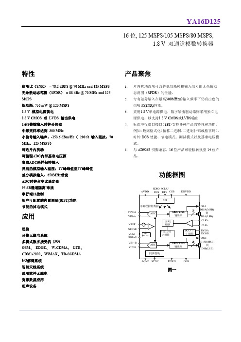
通信 分集无线电系统 多模式数字接受机 (3G) GSM、 EDGE、 W-CDMA、 LTE、 CDMA2000、WiMAX、TD-SCDMA I/O解调系统 智能天线系统 通用软件无线电 宽带数据应用 超声设备
产品聚焦
1. 片内扰动选项可改善低功耗模拟输入信号的无杂散动 态范围(SFDR)的性能。
分辨率
全
16
16
16
位
精度
无失码
全
保证
保证
保证
失调误差
全
±0.2 ±0.4
±0.2 ±0.5
±0.4 ±0.65 % FSR
增益误差
全
±0.4 ±2.5
±0.4 ±2.5
±0.4 ±2.5 % FSR
微分非线性(DNL)1
全
-1.0
+1.4
-1.0
+1.3
-1.0
+1.2 LSB
25℃
±0.65
±0.7
75.9
75.8
dBFs
fIN = 200 MHz
25℃
74.3
72.2
74.0
dBFs
有效位数(ENOB)
fIN = 2.4 MHz
25℃
12.9
12.7
12.7
位
fIN = 70 MHz
25℃
12.8
12.7
12.6
位
fIN = 140 MHz
25℃
12.2
12.3
12.3
位
fIN = 200 MHz
YA16D125
ADC 交流规格
除非另有说明,AVDD = 1.8 V、DRVDD = 1.8 V、最大采样速率、VIN = −1.0 dBFS 差分输入、1.0V 内部基准电压、DCS 使 能。 表 2.
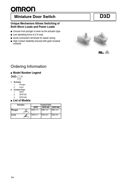
D3D-111中文资料
D3D Miniature Door SwitchUnique Mechanism Allows Switching ofBoth Micro Loads and Power Loads■Choose from plunger or lever as the actuator type.■Low operating force of 2 N max.■Quick-connection terminals for easier wiring.■High contact reliability ensured with gold crossbar contacts.Ordering Information1.Actuator1:Plunger2:Lever2.Contact Form1:SPDT2:SPST-NC3:SPST-NO ■List of Models266267Specifications■RatingsNoteThe ratings values apply under the following test condi-tions.Ambient temperature:20±2°C Ambient humidity:65±5%Operating frequency:20 operations/min■CharacteristicsNote:1.The data given above are initial values.2.The contacts do not open or close for more than 1 ms.3.Consult your OMRON sales representative for details on test conditions.■Approved Standards Consult your OMRON sales representative for specific models with standard approvals.UL1054 (File No. E41515) /CSA C22.2 No. 55 (UL approval)EN61058-1 (File No. 40005053, VDE approval)T esting conditions: 5E4 (50,000 operations), T55 (0°C to 55°C)■Contact SpecificationsNoteFor more information on the minimum applicable load, re-fer to Using Micro Loads on page 269.■Contact FormSPST -NCSPST -NORated voltage Resistive load125 VAC 1 A 250 VAC0.5 AOperating speed 7.5 to 500 mm/sOperating frequency Mechanical:120operations/min max.Electrical:30operations/min max.Insulation resistance100M Ω min. (at 500VDC)Contact resistance (initial value)100 m Ω max.Dielectric strength1,000 VAC, 50/60Hz for 1min between terminals of the same polarity1,500 VAC, 50/60Hz for 1min between current-carrying metal parts and ground, and between each terminal and non-current-carrying metal parts Vibration resistance Malfunction: 10 to 55Hz, 1.5-mm double amplitude Shock resistance (see note 2)Destruction:490 m/s 2 max.Malfunction:300 m/s 2 max.Durability (see note 3)Mechanical:300,000 operations min. (60 operations/min)Electrical:50,000 operations min. (20 operations/min)Degree of protectionIP40Degree of protection against elec-tric shockD3D-1 models (plunger models):Class II D3D-2 models (lever models):Class 0Proof tracking index (PTI)600Ambient operating temperature −30°C to 60°C (with no icing)Ambient operating humidity 85% max.Weight Approx. 4 gD3D125 VAC 1 A 250 VAC0.5 AD3D125 VAC 1 A 250 VAC0.5 AContactSpecification Crossbar MaterialGold alloy Minimum applicable load (see note)1mA at 5VDCDimensions■Dimensions and Operating CharacteristicsNote: 1.All units are in millimeters unless otherwise indicated.2.Unless otherwise specified, a tolerance of ±0.4 mm applies to all dimensions.3.The operating characteristics are for operation in direction A (indicated by the arrow).■Mounting Panel Cutout Dimensions Note All units are in millimeters unless otherwise indicated.■ConnectorsThe terminals connect to JST’s HL Connector.The HL Connector consists of the following components. Contact: SSF-21T-P1.4Housing: HLP-03VOMRON does not sell the HL Connector. Contact the following. J.S.T. Manufacturing Co., Ltd. (Japan)Tel: (81)6-6968-6855Fax: (81)6-6964-2085J.S.T. (U.K.) Ltd. (United Kingdom)Tel: (44)1986-874131Fax: (44)1986-874276J.S.T. Corporation (U.S.A.)Tel: (1)847-473-1957Fax: (1)847-473-1373J.S.T. (H.K.) Co. Ltd. (Hong Kong)Tel: (852)24137979Fax: (852)24111193Type Plunger modelModel D3D-111D3D-121D3D-131OF max.TTF max.2.0 N {204 gf}3.5 N {357 gf}TT9.0 mm (reference value)OP min.OP1(NC-OFF)13 mm13 mm12 mmOP2(NO-ON)12 mmType Lever modelModel D3D-211D3D-221D3D-231OF max.TTF max.2.0 N {204 gf}3.5 N {357 gf}TT9.7 mm (reference value)OP min.OP1(NC-OFF)13 mm13 mm11.5 mmOP2(NO-ON)11.5 mm268Precautions■CautionsHandlingDo not expose the Switch to shocks, such as by dropping it. Doingso may damage or deform the Switch.Do not apply lubrication to the sliding parts, such as pushbuttonsor actuators. Doing so may result in faulty operation or contactfailure.In order to ensure stable contact force for NO contacts, use anoperating stroke of at least 5 mm.■Correct UseMountingThis product does not have a waterproof or drip-proof construc-tion. Ensure that water does not enter the Switch interior. In par-ticular, do not use the Switch in locations where water may bespilt or flow over the Switch. Doing so may result in deteriorationof the insulation.WiringDo not use the Switch with a large force applied to the connectoror lead wire. Doing so may result in rattling or contact failure.Storage EnvironmentStoring the Switch in a plastic bag will help prevent discolorationdue to sulfuration of the (silver-plated) terminals.Do not use the Switch in locations subject to harmful gases or tohigh temperatures or humidity levels. Depending on the location,it is recommended that Switches are inspected between 3 and 6months after the date of manufacturer.Using Micro LoadsEven when using the Switch within the operating range, if thereare inrush currents or surges, it may decrease the durability of theSwitch. If necessary, insert a contact protection circuit.ALL DIMENSIONS SHOWN ARE IN MILLIMETERS.To convert millimeters into inches, multiply by 0.03937. To convert grams into ounces, multiply by 0.03527.Cat. No. B107-E1-01A269。
ENI-1024 增量磁旋转编码器 KIT 用户手册和安装指南说明书

ENI-1024Incremental magnetic rotary encoder KITUser’s Manual and Installation GuideContents1. Safety, policy and warranty.1.1. Safety notes.1.2. Policy.1.3. Warranty.2. Electric specifications.2.1. Operation ranges.2.2. Incremental channels signals.2.3. Differential outputs.2.4. LED indicator.3. Installation guide.3.1 . Description of working.3.2 . Pinout of the connector.3.3 . Installation of the device.1. Safety, policy and warranty.1.1. Safety NotesThe device should not be used where it can cause personal injury, death or high financial loss.1.2. PolicyCNCdrive cannot take responsibility for any personal injury and/or financial loss caused by their devices failure or caused by following an error in this documentation.1.3. WarrantyWe give 12 months of standard warranty period with our ENI-1024 KIT encoders. Customers may send back the device within 15 days from reception date if they are not satisfied with the performance.Using the devices outside of the specified electrical ranges may cause permanent damage to the device and voids warranty.ESD notice: Use ESD protection gloves when installing the device.ESD damage caused by human body discharge to the device excludes from warranty.2. Electric specifications.2.1.Operation ranges.Property Min Typ Max Unit NotesSupply voltage4.5 55.5 VDCSupply current 38 mA Outputs not connectedHigh level output current-20 mALow level output current20 mAEncoder resolution - 1024 - Counts perrevolution In 4X decoding mode. Counting A and B channels’ both the rising and the falling edges.Maximum countfrequency512 kHzHysteresis 2 Counts Hysteresis introduced to avoid flickering of the encoder outputsDifferential non-linearity +-0.176 degreesIntegral non-linearity +-1.4 degrees With magnet displacementof 0.485mm out of thecenter of the sensor. Maximum alloweddisplacement of magnet from center of the sensor. 0.485 mmMeasured on the radiusfrom center of the sensorIC.Ambient temperaturerange-55 +85 °C2.2. Incremental channel signals.The device outputs 90°shifted incremental A and B channel signals. The signal A leads signal B in one rotational direction and signal B leads A in the opposite rotational direction of the magnet. In addition an index signal output is provided which signal is produced on the zero mechanical position, one LSB pulse width and one pulse per full revolution duration.The following figure shows the encoder signals:To avoid the flickering of the encoder signals a 2 counts (LSB) length of hysteresis is introduced.The following figure shows the 2 counts hysteresis:2.3. Differential outputs.All output signals A and B and Index are output as differential signals. This means that each signal has it's negated output too. The differential signals can be transferred in twisted wire pairs to long distance. The differential outputs are produced with the onboard 26LS31 differential line driver chip.The following figure shows the A and _A channel signals in normal operation (when counting) and also in an external short circuit of the wires. The figure is similar for B to _B and for Index to _Index channels:2.3. LED indicator.The device has one LED on the top (connector) side of the panel. The LED indicates if the magnet used for the position sensing is in the correct range for the device to read the mechanical position. If the magnet is in the correct range (1-2mm distance from the surface of the sensor IC) then the LED lights. If the magnet is out of the good range (too close or too far) then the LED light goes off. The sign of the LED makes the correct alignment of the magnet easy to check.3. Installation guide.3.1. Description of working.The device is a rotary encoder module for position sensing in rotary motion. The aluminium hub which includes a magnet at it's end can be attached to a motor shaft. To make the device working place the printed circuit board of the module above the magnet keeping 1-2mm distance with the magnet centered to the center mark on the PCB. The device producing differential incremental A and B channel signals, 1024 edges per full revolution of the magnet. In addition there is an index and _Index output with one counts output per every full rotation. The output signals can be used to measure the relative position of the rotation.The following picture shows the bottom of the printed circuit board with the sensor IC located in the center of the PCB:3.2. Pinout of the connector.The device has a 10 pin IDC crimpable connector. This connector is used to connect the5Volts to power the device and to route out the incremental output signals.The connector is crimpable to a 10 pin ribbon cable or for example to wires of a CAT5/6 patch cable.The following picture and diagram shows the pinout of the connector:Pin number Description1 Ground power input2 +5Volts power input3 Index signal output4 _Index signal output5 A signal output6 _A signal output7 B signal output8 _B signal output9 NC. No internal connection10 NC. No internal connection3.3. Installation of the device.To following steps should done to install the device:a.) Make 2pcs of tapped M3 drills around the motor backshaft (or to the shaft of the installation). The tapped drills should be made on a 25.4 (1 Inch) circle around the midpoint of the shaft on a line alignment (180°) to eachother.b.) Place the magnet holder hub to the motor's backshaft. The hub is pre-drilled with 3mm diameter and should be drilled up if nessessary. Drilling it up can be made on a drillpress with a standard HSS drilling tool. Take care to not drill into the magnet located at the other end of the hub.c.) bolt in the hexagonal spacers to the tapped holes done in point a.d.) crimp your cable to the connector on the encoder PCB.e.) Place the encoder PCB to the top of the hexagonal spacers with the ICs facing down and the connector and LED facing upward. Bolt the PCB to the top of the hexagonal spacers with the supplied M3 screws through the 3mm drills on the PCB.f.) Adjust the hub on the shaft with keeping a 1-2mm distance of the magnet on the hub end to the IC surface on the PCB. Lock the hub to the shaft with bolting the screw located in the side of the hub.g.) Power up the device with providing 5Volts Voltage to it's power pins and check the LED on the top of the PCB. The LED continious on state means a correct alignment of the magnet. If the LED is off after powered means the magnet is out of the correct range and needs to be aligned.For more information visit:e-mail: info@cncdrivePlease consider the enviroment before printing this document.。
PCS-994B_X_频率电压紧急控制装置说明书_国内中文_国内标准版_X_R1.01
S1D13305中文资料
元器件交易网
The information of the product number change
Starting April 1, 2001, the product number will be changed as listed below. To order from April 1, 2001 please use the new product number. For further information, please contact Epson sales representative.
SDU1374#0C SDU1375#0C SDU1376#0C SDU1376BVR SDU1378#0C
• S1D1380x Series New No. Previous No.
SDU1386#0C
New No.
S5U13806P00C
S5U13503P00C S5U13504P00C S5U13505P00C S5U13506P00C
S1D13305 Series S1D13305D00A S1D13305F00A S1D13305F00B
S1D1370x Series S1D13704F00A S1D13705F00A S1D13706B00A S1D13706F00A S1D13708 Series
• S1D1350x Series Previous No.
S5U13704P00C S5U13705P00C S5U13706P00C S5U13706B32R S5U13708P00C
• S1D13A0x Series Previous No.
SDU13A3#0C SDU13A4#0C
New No.
DK125规格书
功能描述DK125是次级反馈,反激式AC-DC 离线式开关电源控制芯片。
芯片采用高集成度的CMOS 电路设计,具有输出短路、次级开路、过温、过压等保护功能。
芯片内置高压功率管和自供电线路,具有外围元件极少,变压器设计简单(变压器不需要供电绕组)等特点。
产品特点l 全电压输入90V —264V 。
l 内置700V 功率管。
l 芯片内集成了高压恒流启动电路,无需外部启动电阻。
l 专利的自供电技术,无需外部绕组供电。
l 待机功耗小于0.3W 。
l 65KHz PWM 开关频率。
l 内置变频功能,待机时自动降低工作频率,在满足欧洲绿色能源标准(<0.3W )同时,降低了输出电压的纹波。
l 内置斜坡补偿电路,保证在低电压及大功率输出时的电路稳定。
l 频率抖动降低EMI 滤波成本。
l 过温、过流、过压以及输出短路,次级开路保护。
l4KV 防静电ESD 测试。
应用领域24W 以下AC-DC 应用包括:电源适配器、LED 电源、电磁炉、空调、DVD 、机顶盒等家电产品。
深圳东科半导体有限公司封装与引脚定义(DIP8)内部框图引脚符号功能描述1GND 接地引脚2GND 接地引脚3FB反馈控制端引脚,接1nF ~10nF4VCC 供电引脚,外部对地接47uF ~100uF 的电容5,6,7,8OC输出引脚,连接芯片内高压功率管,外部与开关变压器相连深圳东科半导体有限公司极限参数供电电压VDD ………………………………………………………-0.3V--8V 供电电流VDD ………………………………………………………100mA引脚电压………………………………………………………-0.3V--VDD+0.3V 功率管耐压………………………………………………………-0.3V--700V 峰值电流………………………………………………………1300mA总耗散功率………………………………………………………1000mW工作温度………………………………………………………-25°C--+125°C 储存温度………………………………………………………-55°C--+150°C 焊接温度………………………………………………………+280°C/5S电气参数项目测试条件最小典型最大单位VCC 工作电压AC 输入85V-----265V 4.54.7 4.9V VCC 启动电压AC 输入85V-----265V 4.7V VCC 重启电压AC 输入85V-----265V 3.30 3.60 3.90V VCC 保护电压AC 输入85V-----265V 6.25 6.55 6.85V VCC 工作电流VCC=5V ,FB=1.5V 50mA 高压启动电流AC 输入85V-----265V0.30.6 1.2mA 启动时间AC 输入85V ------500mS 功率管耐压Ioc=1mA 700------V 功率管保护电压测量OC 电压540600660V 最大峰值电流VCC=5V ,FB=1.5V---2.8V 110012001300mA PWM 输出频率VCC=5V ,FB=1.5V---2.5V 616569KHz VCC=5V ,FB=2.5v-2.8v202224KHz 调制步进频率VCC=5V ,FB=1.5v-2.5v0.5KHz 短路保护阀值测量FB 电压 1.15 1.33 1.50V 变频阀值电压测量FB 电压 2.3 2.5 2.7V 突发模式阀值测量FB 电压2.6 2.83.0V温度保护结温120130140℃深圳东科半导体有限公司前沿消隐时间VCC=5V ,FB=1.5v-2.5v 250ns最小开通时间VCC=5V ,FB=2.6v 500ns 占空比VCC=5V ,FB=1.5v-2.5v 5---70%待机功耗AC 输入265V,空载270mW功能描述上电启动上电启动时,芯片通过内部连接OC 和VCC 引脚的高压电流源,对外部的VCC 储能电容充电,当VCC 电压升高到4.7V 的时候,关闭高压电流源,启动过程结束,控制逻辑开始输出PWM 脉冲。
ads1115中文版
4 个单端或 2 个差分输入 (ADS1115)
可编程比较器
( ADS1114 和 ADS1115)
应用
便携式仪表
消费类商品
电池监测
温度测量
工厂自 动化及过程控制说明
ADS1113、 ADS1114 和 ADS1115 是具有 16 位分辨
率的高精度模数转换器 (ADC), 采用超小型的无引线
250
200
150
AtTA=+25°CandVDD=3.3V,unlessotherwisenoted.
OPERATINGCURRENTvsTEMPERATURESHUTDOWNCURRENTvsTEMPERATURE
5.0
4.5
4.0
VDD= 5V
3.5
3.0
2.5
100
50
0
VDD= 2VVDD= 3.3V
1
LSB
偏移误差
FS = ±2.048V, differential inputs
±1
±3
LSB
FS =±2.048V, single-ended inputs
±3
LSB
失调漂移
FS = ±2.048V
0.005
LSB/°C
偏置电源抑制
FS = ±2.048V
1
LSB/V
增益误差
FS = ±2.048V at 25°C
单位
最小值
典型值
最大值
模拟输入
满量程输入电压
VIN = (AINP) – (AINN)
±4.096/PGA
V
模拟输入电压
AINP or AINN to GND
2019年五年级上册语文生字表拼音部首笔画组词(人教版)

玷辱
瑕玷
圭玷
泯玷
倾玷
33
秉
bǐng
丿
8
秉性
秉烛
秉公
秉政
秉国
秉持
34
谓
wèi
讠
11
称谓
何谓
谓词
可谓
无谓
谓语
35
飕
sōu
风
13
飕飕
飕飗
利飕
彫飕
飕颾
雕飕
36
衰
shuāi
亠
10
衰败
衰弱
衰老
盛衰
兴衰
衰减
36
衰
cuī
亠
10
等衰
37
侨
qiáo
亻
8
华侨
侨胞
归侨
侨民
侨眷
侨属
38
眷
juàn
目
11
眷恋
家眷
眷念
眷属
亲眷
月
13
油腻
腻味
细腻
腻虫
腻歪
滑腻
96
睑
jiǎn
目
12
眼睑
睑裂
睑炎
目睑
睑板
睑下垂
97
眸
móu
目
11
凝眸
眸子
回眸
明眸
低眸
电眸
98
咂
zā
口
8
咂嘴
咂摸
咂儿
咂巴
咯咂
吮咂
99
泻
xiè
氵
8
倾泻
泻药
下泻
泻肚
奔泻
腹泻
100
甥
shēng
- 1、下载文档前请自行甄别文档内容的完整性,平台不提供额外的编辑、内容补充、找答案等附加服务。
- 2、"仅部分预览"的文档,不可在线预览部分如存在完整性等问题,可反馈申请退款(可完整预览的文档不适用该条件!)。
- 3、如文档侵犯您的权益,请联系客服反馈,我们会尽快为您处理(人工客服工作时间:9:00-18:30)。
1. General descriptionThe ADC1113D125 is a dual-channel 11-bit Analog-to-Digital Converter (ADC) optimizedfor high dynamic performance and low power at a sample rate of 125 Msps. Pipelined architecture and output error correction ensure the ADC1113D125 is accurate enough to guarantee zero missing codes over the entire operating range. Supplied from a 3V source for analog and a 1.8V source for the output driver, it embeds two serial outputs. Each lane is differential and complies with the JESD204A format. An integrated Serial Peripheral Interface (SPI) allows the user to easily configure the ADC. A set of ICconfigurations is also available via the binary level control pins taken, which are used at power-up. The device also includes a programmable full-scale SPI to allow flexible input voltage range of 1V to 2V (peak-to-peak).Excellent dynamic performance is maintained from the baseband to input frequencies of 170MHz or more, making the ADC1113D125 ideal for use in communications, imaging, and medical applications.2. Features and benefits3. ApplicationsADC1113D125Dual 11-bit ADC; serial JESD204A interfaceRev. 3 — 10 February 2011Product data sheetSNR, 66.5 dBFS; SFDR, 86 dBc Input bandwidth, 600MHz Sample rate: 125 MspsPower dissipation, 1270mW Clock input divided by 2 for less jittercontributionSPI register programming 3V, 1.8V single supplies Duty Cycle Stabilizer (DCS) Flexible input voltage range:1V (p-p)to 2V (p-p)High IF capabilityTwo configurable serial outputsOffset binary, two’s complement, graycodeTwo JESD204A serial outputs Power-down mode and Sleep mode Pin compatible with ADC1613D series, ADC1413D series, and ADC1213D seriesHVQFN56 packageWireless and wired broadbandcommunications Portable instrumentation Spectral analysisImaging systemsUltrasound equipmentSoftware defined radio4. Ordering information5. Block diagramTable 1.Ordering informationType numberSamplingfrequency (Msps)Package Name DescriptionVersionADC1113D125HN/C1125HVQFN56plastic thermal enhanced very thin quad flat package; no leads; 56 terminals; body 8×8×0.85mmSOT684-76. Pinning information6.1Pinning6.2Pin descriptionTable 2.Pin descriptionSymbol Pin Type[1]DescriptionINAP1I channel A analog inputINAM2I channel A complementary analog inputVCMA3O channel A output common voltageREFAT4O channel A top referenceREFAB5O channel A bottom referenceAGND6G analog groundCLKP7I clock inputCLKM8I complementary clock inputAGND9G analog groundREFBB10O channel B bottom referenceREFBT11O channel B top referenceVCMB12O channel B output common voltageINBM13I channel B complementary analog inputINBP 14I channel B analog input VDDA 15P analog power supply 3V VDDA 16P analog power supply 3V SCLK 17I SPI clock SDIO 18I/O SPI data IO CS 19I chip select AGND 20G analog ground RESET21I JEDEC digital IP reset SCRAMBLER 22I scrambler enable and disableCFG023I/O see Table 28 (input) or OTRA (output)[2]CFG124I/O see Table 28 (input) or OTRB (output)[2]CFG225I/O see Table 28 (input)CFG326I/O see Table 28 (input)VDDD 27P digital power supply 1.8V DGND 28G digital ground DGND 29G digital ground DGND 30G digital groundVDDD 31P digital power supply 1.8V CMLPB 32O channel B outputCMLNB 33O channel B complementary output VDDD 34P digital power supply 1.8V DGND 35G digital ground DGND 36G digital groundVDDD 37P digital power supply 1.8V CMLNA 38O channel A complementary output CMLPA 39O channel A output VDDD 40P digital power supply 1.8 V DGND 41G digital ground DGND 42G digital groundSYNCP 43I synchronization from FPGA SYNCN 44I synchronization from FPGA DGND 45G digital groundVDDD 46P digital power supply 1.8VSWING_047I JESD204 serial buffer programmable output swing SWING_148I JESD204 serial buffer programmable output swing DNC 49O do not connectVDDA 50P analog power supply 3V AGND 51G analog ground AGND52Ganalog groundTable 2.Pin description …continuedSymbol Pin Type [1]DescriptionTable 2.Pin description …continuedSymbol Pin Type[1]DescriptionVDDA 53P analog power supply 3VSENSE54I reference programming pinVREF55I/O voltage reference input/outputVDDA 56P analog power supply 3V[1]P: power supply; G: ground; I: input; O: output; I/O: input/output.[2]OTRA stands for “OuT of Range” A. OTRB stands for “OuT of Range” B.7. Limiting valuesTable 3.Limiting valuesIn accordance with the Absolute Maximum Rating System (IEC 60134).Symbol Parameter Conditions Min Max UnitV DDA analog supply voltage−0.4+4.6VV DDD digital supply voltage−0.4+2.5VT stg storage temperature−55+125°CT amb ambient temperature−40+85°CT j junction temperature-125°C 8. Thermal characteristicsTable 4.Thermal characteristicsSymbol Parameter Conditions Typ UnitR th(j-a)thermal resistance from junction to ambient[1]17.8K/WR th(j-c)thermal resistance from junction to case[1] 6.8K/W[1]Value for six layers board in still air with a minimum of 25 thermal vias.9.Static characteristicsTable 5.Static characteristics[1]Symbol Parameter Conditions Min Typ Max Unit SuppliesV DDA analog supply voltage 2.85 3.0 3.4VV DDD digital supply voltage 1.65 1.8 1.95VI DDA analog supply current f clk=125Msps;-343-mAf i=70MHz-150-mA I DDD digital supply current f clk=125Msps;f i=70MHzP tot total power dissipation f clk=125Msps-1270-mW P power dissipation Power-down mode-30-mWStandby mode-200-mW Clock inputs: pins CLKP and CLKM (AC-coupled)Low-Voltage Positive Emitter-Coupled Logic (LVPECL)peak-to-peak-±1.6-VV i(clk)dif differential clock inputvoltageSINEpeak-to-peak-±3.0-VV i(clk)dif differential clock inputvoltageLow Voltage Complementary Metal Oxide Semiconductor (LVCMOS)V IL LOW-level input voltage--0.3V DDA VV IH HIGH-level input voltage0.7V DDA--V Logic inputs, Power-down: pins CFG0to CFG3, SCRAMBLER, SWING_0, SWING_1, and RESETV IL LOW-level input voltage-0-VV IH HIGH-level input voltage-0.66V DDD-VI IL LOW-level input current−6-+6μA I IH HIGH-level input current−30-+30μA SPI: pins CS, SDIO, and SCLKV IL LOW-level input voltage0-0.3V DDA VV IH HIGH-level input voltage0.7V DDA-V DDA VI IL LOW-level input current−10-+10μA I IH HIGH-level input current−50-+50μA C I input capacitance-4-pFAnalog inputs: pins INAP, INAM, INBP, and INBMI I input current track mode−5-+5μA R I input resistance track mode-15-ΩC I input capacitance track mode-5-pF V I(cm)common-mode inputvoltagetrack mode0.9 1.52VB i input bandwidth-600-MHz V I(dif)differential input voltage peak-to-peak1-2V Voltage controlled regulator output: pins VCMA and VCMBV O(cm)common-mode outputvoltage-V DDA / 2-VI O(cm)common-mode outputcurrent-4-mA Reference voltage input/output: pin VREFV VREF voltage on pin VREF output0.5-1Vinput0.5-1V Data outputs: pins CMLPA, CMLNAOutput levels, V DDD=1.8V; SWING_SEL[2:0]=000V OL LOW-level outputvoltage DC coupled; output- 1.5-V AC coupled- 1.35-VV OH HIGH-level outputvoltage DC coupled; output- 1.8-V AC coupled - 1.65-VOutput levels, V DDD=1.8V; SWING_SEL[2:0]=001V OL LOW-level outputvoltage DC coupled; output- 1.45-V AC coupled - 1.275-VV OH HIGH-level outputvoltage DC coupled; output- 1.8-V AC coupled - 1.625-VOutput levels, V DDD=1.8V; SWING_SEL[2:0]=010V OL LOW-level outputvoltage DC coupled; output- 1.4-V AC coupled - 1.2-VV OH HIGH-level outputvoltage DC coupled; output- 1.8-V AC coupled - 1.6-VOutput levels, V DDD=1.8V; SWING_SEL[2:0]=011V OL LOW-level outputvoltage DC coupled; output- 1.35-V AC coupled - 1.125-VV OH HIGH-level outputvoltage DC coupled; output- 1.8-V AC coupled - 1.575-VOutput levels, V DDD=1.8V; SWING_SEL[2:0]=100V OL LOW-level outputvoltage DC coupled; output- 1.3-V AC coupled - 1.05-VV OH HIGH-level outputvoltage DC coupled; output- 1.8-V AC coupled - 1.55-VTable 5.Static characteristics[1] …continuedSymbol Parameter Conditions Min Typ Max Unit[1]Typical values measured at V DDA =3V,V DDD =1.8V, T amb =25°C. Minimum and maximum values are across the full temperature range T amb =−40°C to +85°C at V DDA =3V, V DDD =1.8V; V I (INAP , INBP)−V I (INAM, INBM)=−1dBFS; internal reference mode; 100Ω differential applied to serial outputs; unless otherwise specified.Serial configuration: pins SYNCCP , SYNCCNV IL LOW-level input voltagedifferential; input-0.95-V V IHHIGH-level input voltage differential; input - 1.47-V Accuracy INL integral non-linearity −5-+5LSB DNL differential non-linearity no missing codes guaranteed −0.95±0.25+0.95LSB E offset offset error -±2-mV E G gain errorfull-scale-±0.5-%M G(CTC)channel-to-channel gain matching- 1.1-%Supply PSRRpower supply rejection ratio200mV (p-p) on pin VDDA; f i =DC-−54-dBTable 5.Static characteristics [1] …continuedSymbol ParameterConditions Min Typ Max Unit10.Dynamic characteristics10.1Dynamic characteristicsTable 6.Dynamic characteristics[1]Symbol Parameter Conditions Min Typ Max Unit Analog signal processingα2H second harmonic level f i=3MHz-88-dBcf i=30MHz-87-dBcf i=70MHz-85-dBcf i=170MHz-83-dBcα3H third harmonic level f i=3MHz-87-dBcf i=30MHz-86-dBcf i=70MHz-84-dBcf i=170MHz-82-dBcTHD total harmonic distortion f i=3MHz-84-dBcf i=30MHz-83-dBcf i=70MHz-81-dBcf i=170MHz-79-dBc ENOB effective number of bits f i=3MHz-10.7-bitsf i=30MHz-10.7-bitsf i=70MHz-10.7-bitsf i=170MHz-10.6-bitsSNR signal-to-noise ratio f i=3MHz-66.2-dBFSf i=30MHz-66.2-dBFSf i=70MHz-66.0-dBFSf i=170MHz-65.8-dBFS SFDR spurious-free dynamic range f i=3MHz-87-dBcf i=30MHz-86-dBcf i=70MHz-84-dBcf i=170MHz-82-dBcIMD intermodulation distortion f i=3MHz-89-dBcf i=30MHz-88-dBcf i=70MHz-86-dBcf i=170MHz-84-dBcαct(ch)channel crosstalk f i=70MHz-100-dBc[1]Typical values measured at V DDA=3V,V DDD=1.8V, T amb=25°C. Minimum and maximum values are across the full temperaturerange T amb=−40°C to +85°C at V DDA=3V, V DDD=1.8V; V I(INAP, INBP)−V I(INAM, INBM)=−1dBFS; internal reference mode;100Ω differential applied to serial outputs; unless otherwise specified.10.2Clock and digital output timingTable 7.Characteristics[1]Symbol Parameter Conditions Min Typ Max Unit Clock timing input: pins CLKP and CLKMf clk clock frequency100-125Mspst lat(data)data latency time-14-clock cycle δclk clock duty cycle DCS_EN=logic1305070%DCS_EN=logic0455055%t d(s)sampling delay time-0.8-nst wake wake-up time-76-μs[1]Typical values measured at V DDA=3V,V DDD=1.8V, T amb=25°C. Minimum and maximum values are across the full temperaturerange T amb=−40°C to +85°C at V DDA=3V, V DDD=1.8V; V I(INAP, INBP)−V I(INAM, INBM)=−1dBFS; internal reference mode;100W differential applied to serial outputs; unless otherwise specified.10.3Serial output timingThe eye diagram of the serial output is shown in Figure3 and Figure4. Test conditionsare:• 3.125 Gbps data rate•T amb=25°C•DC coupling with two different receiver common-mode voltages分销商库存信息:NXPADC1113D125HN/C1:5ADC1113D125HN/C1,5。
