Multiple model predictive control of hemodynamic variables — an experimental study
Design and Implementation of a Bionic Robotic Hand
Design and Implementation of a Bionic Robotic Hand with Multimodal Perception Based on ModelPredictive Controlline 1:line 2:Abstract—This paper presents a modular bionic robotic hand system based on Model Predictive Control (MPC). The system's main controller is a six-degree-of-freedom STM32 servo control board, which employs the Newton-Euler method for a detailed analysis of the kinematic equations of the bionic robotic hand, facilitating the calculations of both forward and inverse kinematics. Additionally, MPC strategies are implemented to achieve precise control of the robotic hand and efficient execution of complex tasks.To enhance the environmental perception capabilities of the robotic hand, the system integrates various sensors, including a sound sensor, infrared sensor, ultrasonic distance sensor, OLED display module, digital tilt sensor, Bluetooth module, and PS2 wireless remote control module. These sensors enable the robotic hand to perceive and respond to environmental changes in real time, thereby improving operational flexibility and precision. Experimental results indicate that the bionic robotic hand system possesses flexible control capabilities, good synchronization performance, and broad application prospects.Keywords-Bionic robotic hand; Model Predictive Control (MPC); kinematic analysis; modular designI. INTRODUCTIONWith the rapid development of robotics technology, the importance of bionic systems in industrial and research fields has grown significantly. This study presents a bionic robotic hand, which mimics the structure of the human hand and integrates an STM32 microcontroller along with various sensors to achieve precise and flexible control. Traditional control methods for robotic hands often face issues such as slow response times, insufficient control accuracy, and poor adaptability to complex environments. To address these challenges, this paper employs the Newton-Euler method to establish a dynamic model and introduces Model Predictive Control (MPC) strategies, significantly enhancing the control precision and task execution efficiency of the robotic hand.The robotic hand is capable of simulating basic human arm movements and achieves precise control over each joint through a motion-sensing glove, enabling it to perform complex and delicate operations. The integration of sensors provides the robotic hand with biological-like "tactile," "auditory," and "visual" capabilities, significantly enhancing its interactivity and level of automation.In terms of applications, the bionic robotic hand not only excels in industrial automation but also extends its use to scientific exploration and daily life. For instance, it demonstrates high reliability and precision in extreme environments, such as simulating extraterrestrial terrain and studying the possibility of life.II.SYSTEM DESIGNThe structure of the bionic robotic hand consists primarily of fingers with multiple joint degrees of freedom, where each joint can be controlled independently. The STM32 servo acts as the main controller, receiving data from sensors positioned at appropriate locations on the robotic hand, and controlling its movements by adjusting the joint angles. To enhance the control of the robotic hand's motion, this paper employs the Newton-Euler method to establish a dynamic model, conducts kinematic analysis, and integrates Model Predictive Control (MPC) strategies to improve operational performance in complex environments.In terms of control methods, the system not only utilizes a motion-sensing glove for controlling the bionic robotic hand but also integrates a PS2 controller and a Bluetooth module, achieving a fusion of multiple control modalities.整整整整如图需要预留一个图片的位置III.HARDWARE SELECTION AND DESIGN Choosing a hardware module that meets the functional requirements of the system while effectively controlling costs and ensuring appropriate performance is a critical consideration prior to system design.The hardware components of the system mainly consist of the bionic robotic hand, a servo controller system, a sound module, an infrared module, an ultrasonic distance measurement module, and a Bluetooth module. The main sections are described below.A.Bionic Mechanical StructureThe robotic hand consists of a rotating base and five articulated fingers, forming a six-degree-of-freedom motion structure. The six degrees of freedom enable the system to meet complex motion requirements while maintaining high efficiency and response speed. The workflow primarily involves outputting different PWM signals from a microcontroller to ensure that the six degrees of freedom of the robotic hand can independently control the movements of each joint.B.Controller and Servo SystemThe control system requires a variety of serial interfaces. To achieve efficient control, a combination of the STM32 microcontroller and Arduino control board is utilized, leveraging the advantages of both. The STM32 microcontroller serves as the servo controller, while the Arduino control board provides extensive interfaces and sensor support, facilitating simplified programming and application processes. This integration ensures rapid and precise control of the robotic hand and promotes efficient development.C.Bluetooth ModuleThe HC-05 Bluetooth module supports full-duplex serial communication at distances of up to 10 meters and offers various operational modes. In the automatic connection mode, the module transmits data according to a preset program. Additionally, it can receive AT commands in command-response mode, allowing users to configure control parameters or issue control commands. The level control of external pins enables dynamic state transitions, making the module suitable for a variety of control scenarios.D.Ultrasonic Distance Measurement ModuleThe US-016 ultrasonic distance measurement module provides non-contact distance measurement capabilities of up to 3 meters and supports various operating modes. In continuous measurement mode, the module continuously emits ultrasonic waves and receives reflected signals to calculate the distance to an object in real-time. Additionally, the module can adjust the measurement range or sensitivity through configuration response mode, allowing users to set distance measurement parameters or modify the measurement frequency as needed. The output signal can dynamically reflect the measurement results via level control of external pins, making it suitable for a variety of distance sensing and automatic control applications.IV. DESIGN AND IMPLEMENTATION OF SYSTEMSOFTWAREA.Kinematic Analysis and MPC StrategiesThe control research of the robotic hand is primarily based on a mathematical model, and a reliable mathematical model is essential for studying the controllability of the system. The Denavit-Hartenberg (D-H) method is employed to model the kinematics of the bionic robotic hand, assigning a local coordinate system to each joint. The Z-axis is aligned with the joint's rotation axis, while the X-axis is defined as the shortest distance between adjacent Z-axes, thereby establishing the coordinate system for the robotic hand.By determining the Denavit-Hartenberg (D-H) parameters for each joint, including joint angles, link offsets, link lengths, and twist angles, the transformation matrix for each joint is derived, and the overall transformation matrix from the base to the fingertip is computed. This matrix encapsulates the positional and orientational information of the fingers in space, enabling precise forward and inverse kinematic analyses. The accuracy of the model is validated through simulations, confirming the correct positioning of the fingertip actuator. Additionally, Model Predictive Control (MPC) strategies are introduced to efficiently control the robotic hand and achieve trajectory tracking by predicting system states and optimizing control inputs.Taking the index finger as an example, the Denavit-Hartenberg (D-H) parameter table is established.The data table is shown in Table ITABLE I. DATA SHEETjoints, both the forward kinematic solution and the inverse kinematic solution are derived, resulting in the kinematic model of the ing the same approach, the kinematic models for all other fingers can be obtained.The movement space of the index finger tip is shownin Figure 1.Fig. 1.Fig. 1.The movement space at the end of the index finger Mathematical Model of the Bionic Robotic Hand Based on the Newton-Euler Method. According to the design, each joint of the bionic robotic hand has a specified degree of freedom.For each joint i, the angle is defined as θi, the angular velocity asθi, and the angular acceleration as θi.The dynamics equation for each joint can be expressed as:τi=I iθi+w i(I i w i)whereτi is the joint torque, I i is the joint inertia matrix, and w i and θi represent the joint angular velocity and acceleration, respectively.The control input is generated by the motor driver (servo), with the output being torque. Assuming the motor input for each joint is u i, the joint torque τi can be mapped through the motor's torque constant as:τi=kτ∙u iThe system dynamics equation can be described as:I iθi+b iθi+c iθi=τi−τext,iwhere b i is the damping coefficient, c i is the spring constant (accounting for joint elasticity), and τext,i represents external torques acting on the joint i, such as gravity and friction.The primary control objective is to ensure that the end-effector of the robotic hand (e.g., fingertip) can accurately track a predefined trajectory. Let the desired trajectory be denoted as y d(t)and the actual trajectory as y(t)The tracking error can be expressed as:e(t)=y d(t)−y(t)The goal of MPC is to minimize the cumulative tracking error, which is typically achieved through the following objective function:J=∑[e(k)T Q e e(k)]N−1k=0where Q e is the error weight matrix, N is the prediction horizon length.Mechanical constraints require that the joint angles and velocities must remain within the physically permissible range. Assuming the angle range of the i-th joint is[θi min,θi max]and the velocity range is [θi min,θi max]。
预测控制

g11=poly2tfd(12.8,[16.7,1],0,1);%POL Y2TFD Create transfer functions in 3 row representation将通用的传递函数模型转换为MPC传递函数模型% g = poly2tfd(num,den,delt,delay)% POL Y2TFD creates a MPC toolbox transfer function in following format:%g为对象MPC传递函数模型% g = [ b0 b1 b2 ... ] (numerator coefficients)% | a0 a1 a2 ... | (denominator coefficients)% [ delt delay 0 ... ] (only first 2 elements used in this row)%% Inputs:% num : Coefficients of the transfer function numerator.% den : Coefficients of the transfer function denominator.% delt : Sampling time. Can be 0 (for continuous-time system)% or > 0 (for discrete-time system). Default is 0.% delay : Pure time delay (dead time). Can be >= 0.% If omitted or empty, set to zero.% For discrete-time systems, enter as PERIODS of pure% delay (an integer). Otherwise enter in time units.g21=poly2tfd(6.6,[10.9,1],0,7);g12=poly2tfd(-18.9,[21.0,1],0,3);g22=poly2tfd(-19.4,[14.4,1],0,3);delt=3;ny=2;tfinal=90;model=tfd2step(tfinal,delt,ny,g11,g21,g12,g22)%对于这个例子,N=90/3=30figure(3)plot(model)%TFD2STEP Determines the step response model of a transfer function model.传递函数模型转换成阶跃响应模型% plant = tfd2step(tfinal, delt2, nout, g1)% plant = tfd2step(tfinal, delt2, nout, g1, ..., g25)% The transfer function model can be continuous or discrete.%% Inputs:% tfinal: truncation time for step response model.% delt2: desired sampling interval for step response model.% nout: output stability indicator. For stable systems, this% argument is set equal to number of outputs, ny.% For systems with one or more integrating outputs,% this argument is a column vector of length ny with% nout(i)=0 indicating an integrating output and% nout(i)=1 indicating a stable output.% g1, g2,...: SISO transfer function described above ordered% to be read in columnwise (by input). The number of % transfer functions required is ny*nu. (nu=number of % inputs). Limited to ny*nu <= 25.%% Output:% plant: step response coefficient matrix in MPC step format. plant=model;P=6;M=2;ywt=[];uwt=[1 1];Kmpc=mpccon(model,ywt,uwt,M,P)%ywt,uwt : 相当于Q,R%MPCCON Calculate MPC controller gains for unconstrained case.% Kmpc = mpccon(model,ywt,uwt,M,P)% MPCCON uses a step-response model of the process.% Inputs:% model : Step response coefficient matrix of model.% ywt,uwt : matrices of constant or time-varying weights.相当于Q,R% If the trajectory is too short, they are kept constant% for the remaining time steps.% M : number of input moves and blocking specification. If% M contains only one element it is the input horizon% length. If M contains more than one element% then each element specifies blocking intervals.% P : output (prediction) horizon length. P = Inf indicates the% infinite horizon.%% Output:% Kmpc : Controller gain matrixtend=30;r=[0 1];[y,u]=mpcsim(plant,model,Kmpc,tend,r);%plan为开环对象的实际阶跃响应模型%model为辨识得到的开环阶跃响应模型%Kmpc相当于D阵%Tend仿真的结束时间.%R输出设定值和参考轨迹%r=[r1(1) r2(1)...rny(1);r1(2) r2(2)....rny(2);... r1(N) r2(N) ...rny(N)]%y:控制输出%u:控制变量%ym:模型预测输出%MPCSIM Simulation of the unconstrained Model Predictive Controller.% [y,u,ym] = mpcsim(plant, model, Kmpc, tend, r,usat, tfilter,% dplant, dmodel, dstep)% REQUIRED INPUTS:% plant(model): the step response coefficient matrix of the plant (model)% generated by the function tfd2step% Kmpc: the constant control law matrix computed by the function mpccon% (closed-loop simulations).For open-loop simulation, controller=[].% tend: final time of simulation.% r: for the closed-loop simulation, it is a constant or time-varying% reference trajectory. For the open-loop simulation, it is the% trajectory of the manipulated variable u.% OPTIONAL INPUTS:% usat: the matrix of manipulated variable constraints.It is a constant% or time-varying trajectory of the lower limits (Ulow), upper limits% (Uhigh) and rate of change limits (DelU) on the manipulated % variables. Default=[].% tfilter: time constants for noise filter and unmeasured disturbance lags.% Default is no filtering and step disturbance.% dplant: step response coefficient matrix for the disturbance effect on the% plant output generated by the function tfd2step. If distplant is% provided, dstep is also required. Default = [].% dmodel: step response coefficient matrix for the measured disturbance% effect on the model output generated by the function tfd2step.% If distmodel is provided, dstep is also required. Default=[].% dstep: matrix of disturbances to the plant. For output step disturbances% it is a constant or time-varying trajectory of disturbance values% For disturbances through step response models,it is a constant or% time-varying trajectory of disturbance model inputs.Default=[].% OUTPUT ARGUMENTS: y (system response), u (manipulated variable) and% ym (model response)plotall(y,u,delt)figure(2)plot(y,'*')南通大学毕业设计(论文)任务书题目锅炉液位系统的DMC-PID控制学生姓名朱养兵学院电气工程学院专业自动化班级自051学号0512012010起讫日期2009.2 -2009.6指导教师李俊红职称讲师发任务书日期2009 年2 月18 日●MATLAB 软件●JX-300X组态监控软件●浙大中控DCS●上海齐鑫公司过程控制对象●PC机。
机器人顶刊论文
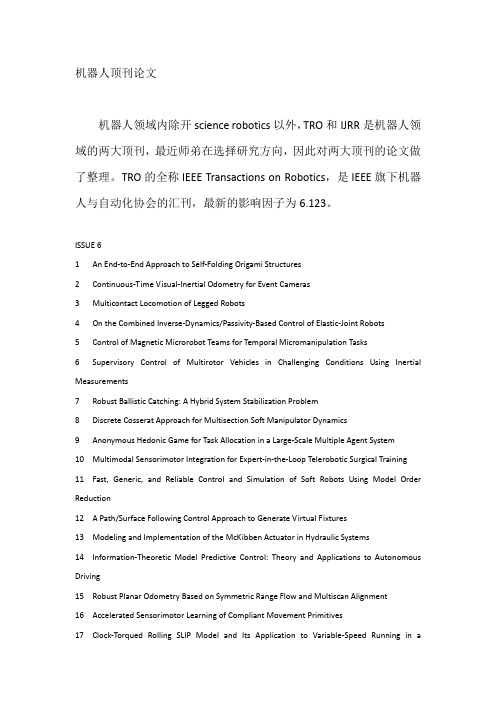
机器人顶刊论文机器人领域内除开science robotics以外,TRO和IJRR是机器人领域的两大顶刊,最近师弟在选择研究方向,因此对两大顶刊的论文做了整理。
TRO的全称IEEE Transactions on Robotics,是IEEE旗下机器人与自动化协会的汇刊,最新的影响因子为6.123。
ISSUE 61 An End-to-End Approach to Self-Folding Origami Structures2 Continuous-Time Visual-Inertial Odometry for Event Cameras3 Multicontact Locomotion of Legged Robots4 On the Combined Inverse-Dynamics/Passivity-Based Control of Elastic-Joint Robots5 Control of Magnetic Microrobot Teams for Temporal Micromanipulation Tasks6 Supervisory Control of Multirotor Vehicles in Challenging Conditions Using Inertial Measurements7 Robust Ballistic Catching: A Hybrid System Stabilization Problem8 Discrete Cosserat Approach for Multisection Soft Manipulator Dynamics9 Anonymous Hedonic Game for Task Allocation in a Large-Scale Multiple Agent System10 Multimodal Sensorimotor Integration for Expert-in-the-Loop Telerobotic Surgical Training11 Fast, Generic, and Reliable Control and Simulation of Soft Robots Using Model Order Reduction12 A Path/Surface Following Control Approach to Generate Virtual Fixtures13 Modeling and Implementation of the McKibben Actuator in Hydraulic Systems14 Information-Theoretic Model Predictive Control: Theory and Applications to Autonomous Driving15 Robust Planar Odometry Based on Symmetric Range Flow and Multiscan Alignment16 Accelerated Sensorimotor Learning of Compliant Movement Primitives17 Clock-Torqued Rolling SLIP Model and Its Application to Variable-Speed Running in aHexapod Robot18 On the Covariance of X in AX=XB19 Safe Testing of Electrical Diathermy Cutting Using a New Generation Soft ManipulatorISSUE 51 Toward Dexterous Manipulation With Augmented Adaptive Synergies: The Pisa/IIT SoftHand 22 Efficient Equilibrium Testing Under Adhesion and Anisotropy Using Empirical Contact Force Models3 Force, Impedance, and Trajectory Learning for Contact Tooling and Haptic Identification4 An Ankle–Foot Prosthesis Emulator With Control of Plantarflexion and Inversion–Eversion Torque5 SLAP: Simultaneous Localization and Planning Under Uncertainty via Dynamic Replanning in Belief Space6 An Analytical Loading Model for n -Tendon Continuum Robots7 A Direct Dense Visual Servoing Approach Using Photometric Moments8 Computational Design of Robotic Devices From High-Level Motion Specifications9 Multicontact Postures Computation on Manifolds10 Stiffness Modulation in an Elastic Articulated-Cable Leg-Orthosis Emulator: Theory and Experiment11 Human–Robot Communications of Probabilistic Beliefs via a Dirichlet Process Mixture of Statements12 Multirobot Reconnection on Graphs: Problem, Complexity, and Algorithms13 Robust Intrinsic and Extrinsic Calibration of RGB-D Cameras14 Reactive Trajectory Generation for Multiple Vehicles in Unknown Environments With Wind Disturbances15 Resource-Aware Large-Scale Cooperative Three-Dimensional Mapping Using Multiple Mobile Devices16 Control of Planar Spring–Mass Running Through Virtual Tuning of Radial Leg Damping17 Gait Design for a Snake Robot by Connecting Curve Segments and ExperimentalDemonstration18 Server-Assisted Distributed Cooperative Localization Over Unreliable Communication Links19 Realization of Smooth Pursuit for a Quantized Compliant Camera Positioning SystemISSUE 41 A Survey on Aerial Swarm Robotics2 Trajectory Planning for Quadrotor Swarms3 A Distributed Control Approach to Formation Balancing and Maneuvering of Multiple Multirotor UAVs4 Joint Coverage, Connectivity, and Charging Strategies for Distributed UAV Networks5 Robotic Herding of a Flock of Birds Using an Unmanned Aerial Vehicle6 Agile Coordination and Assistive Collision Avoidance for Quadrotor Swarms Using Virtual Structures7 Decentralized Trajectory Tracking Control for Soft Robots Interacting With the Environment8 Resilient, Provably-Correct, and High-Level Robot Behaviors9 Humanoid Dynamic Synchronization Through Whole-Body Bilateral Feedback Teleoperation10 Informed Sampling for Asymptotically Optimal Path Planning11 Robust Tactile Descriptors for Discriminating Objects From Textural Properties via Artificial Robotic Skin12 VINS-Mono: A Robust and Versatile Monocular Visual-Inertial State Estimator13 Zero Step Capturability for Legged Robots in Multicontact14 Fast Gait Mode Detection and Assistive Torque Control of an Exoskeletal Robotic Orthosis for Walking Assistance15 Physically Plausible Wrench Decomposition for Multieffector Object Manipulation16 Considering Uncertainty in Optimal Robot Control Through High-Order Cost Statistics17 Multirobot Data Gathering Under Buffer Constraints and Intermittent Communication18 Image-Guided Dual Master–Slave Robotic System for Maxillary Sinus Surgery19 Modeling and Interpolation of the Ambient Magnetic Field by Gaussian Processes20 Periodic Trajectory Planning Beyond the Static Workspace for 6-DOF Cable-Suspended Parallel Robots1 Computationally Efficient Trajectory Generation for Fully Actuated Multirotor Vehicles2 Aural Servo: Sensor-Based Control From Robot Audition3 An Efficient Acyclic Contact Planner for Multiped Robots4 Dimensionality Reduction for Dynamic Movement Primitives and Application to Bimanual Manipulation of Clothes5 Resolving Occlusion in Active Visual Target Search of High-Dimensional Robotic Systems6 Constraint Gaussian Filter With Virtual Measurement for On-Line Camera-Odometry Calibration7 A New Approach to Time-Optimal Path Parameterization Based on Reachability Analysis8 Failure Recovery in Robot–Human Object Handover9 Efficient and Stable Locomotion for Impulse-Actuated Robots Using Strictly Convex Foot Shapes10 Continuous-Phase Control of a Powered Knee–Ankle Prosthesis: Amputee Experiments Across Speeds and Inclines11 Fundamental Actuation Properties of Multirotors: Force–Moment Decoupling and Fail–Safe Robustness12 Symmetric Subspace Motion Generators13 Recovering Stable Scale in Monocular SLAM Using Object-Supplemented Bundle Adjustment14 Toward Controllable Hydraulic Coupling of Joints in a Wearable Robot15 Geometric Construction-Based Realization of Spatial Elastic Behaviors in Parallel and Serial Manipulators16 Dynamic Point-to-Point Trajectory Planning Beyond the Static Workspace for Six-DOF Cable-Suspended Parallel Robots17 Investigation of the Coin Snapping Phenomenon in Linearly Compliant Robot Grasps18 Target Tracking in the Presence of Intermittent Measurements via Motion Model Learning19 Point-Wise Fusion of Distributed Gaussian Process Experts (FuDGE) Using a Fully Decentralized Robot Team Operating in Communication-Devoid Environment20 On the Importance of Uncertainty Representation in Active SLAM1 Robust Visual Localization Across Seasons2 Grasping Without Squeezing: Design and Modeling of Shear-Activated Grippers3 Elastic Structure Preserving (ESP) Control for Compliantly Actuated Robots4 The Boundaries of Walking Stability: Viability and Controllability of Simple Models5 A Novel Robotic Platform for Aerial Manipulation Using Quadrotors as Rotating Thrust Generators6 Dynamic Humanoid Locomotion: A Scalable Formulation for HZD Gait Optimization7 3-D Robust Stability Polyhedron in Multicontact8 Cooperative Collision Avoidance for Nonholonomic Robots9 A Physics-Based Power Model for Skid-Steered Wheeled Mobile Robots10 Formation Control of Nonholonomic Mobile Robots Without Position and Velocity Measurements11 Online Identification of Environment Hunt–Crossley Models Using Polynomial Linearization12 Coordinated Search With Multiple Robots Arranged in Line Formations13 Cable-Based Robotic Crane (CBRC): Design and Implementation of Overhead Traveling Cranes Based on Variable Radius Drums14 Online Approximate Optimal Station Keeping of a Marine Craft in the Presence of an Irrotational Current15 Ultrahigh-Precision Rotational Positioning Under a Microscope: Nanorobotic System, Modeling, Control, and Applications16 Adaptive Gain Control Strategy for Constant Optical Flow Divergence Landing17 Controlling Noncooperative Herds with Robotic Herders18 ε⋆: An Online Coverage Path Planning Algorithm19 Full-Pose Tracking Control for Aerial Robotic Systems With Laterally Bounded Input Force20 Comparative Peg-in-Hole Testing of a Force-Based Manipulation Controlled Robotic HandISSUE 11 Development of the Humanoid Disaster Response Platform DRC-HUBO+2 Active Stiffness Tuning of a Spring-Based Continuum Robot for MRI-Guided Neurosurgery3 Parallel Continuum Robots: Modeling, Analysis, and Actuation-Based Force Sensing4 A Rationale for Acceleration Feedback in Force Control of Series Elastic Actuators5 Real-Time Area Coverage and Target Localization Using Receding-Horizon Ergodic Exploration6 Interaction Between Inertia, Viscosity, and Elasticity in Soft Robotic Actuator With Fluidic Network7 Exploiting Elastic Energy Storage for “Blind”Cyclic Manipulation: Modeling, Stability Analysis, Control, and Experiments for Dribbling8 Enhance In-Hand Dexterous Micromanipulation by Exploiting Adhesion Forces9 Trajectory Deformations From Physical Human–Robot Interaction10 Robotic Manipulation of a Rotating Chain11 Design Methodology for Constructing Multimaterial Origami Robots and Machines12 Dynamically Consistent Online Adaptation of Fast Motions for Robotic Manipulators13 A Controller for Guiding Leg Movement During Overground Walking With a Lower Limb Exoskeleton14 Direct Force-Reflecting Two-Layer Approach for Passive Bilateral Teleoperation With Time Delays15 Steering a Swarm of Particles Using Global Inputs and Swarm Statistics16 Fast Scheduling of Robot Teams Performing Tasks With Temporospatial Constraints17 A Three-Dimensional Magnetic Tweezer System for Intraembryonic Navigation and Measurement18 Adaptive Compensation of Multiple Actuator Faults for Two Physically Linked 2WD Robots19 General Lagrange-Type Jacobian Inverse for Nonholonomic Robotic Systems20 Asymmetric Bimanual Control of Dual-Arm Exoskeletons for Human-Cooperative Manipulations21 Fourier-Based Shape Servoing: A New Feedback Method to Actively Deform Soft Objects into Desired 2-D Image Contours22 Hierarchical Force and Positioning Task Specification for Indirect Force Controlled Robots。
model predictive control

Past
MPC: basic idea (from Bo Wahlberg)
Figure by MIT OpenCourseWare.
June 18, 2008
Spr 2008
16.323 16–2
• Note that the control algorithm is based on numerically solving an optimization problem at each step – Typically a constrained optimization • Main advantage of MPC: – Explicitly accounts for system constraints. � Doesn’t just design a controller to keep the system away from them. – Can easily handle nonlinear and time-varying plant dynamics, since the controller is explicitly a function of the model that can be mod ified in real-time (and plan time)
MIT OpenCourseWare
16.323 Principles of Optimal Control
Spring 2008
For information about citing these materials or our Terms of Use, visit: /terms.
• Typical problem statement: for finite N (F = 0) min J =
模型预测控制
,得最优控制率:
根据滚动优化原理,只实施目前控制量u2(k):
式中:
多步优化MAC旳特点: 优点: (i)控制效果和鲁棒性优于单步MAC算法简朴;
(ii)合用于有时滞或非最小相位对象。 缺陷: (i)算法较单步MAC复杂;
(ii)因为以u作为控制量, 造成MAC算法不可防止地出现稳态误差.
第5章 模型预测控制
5.3.1.2 反馈校正 为了在模型失配时有效地消除静差,能够在模型预测值ym旳基础上 附加一误差项e,即构成反馈校正(闭环预测)。
详细做法:将第k时刻旳实际对象旳输出测量值与预测模型输出之间 旳误差附加到模型旳预测输出ym(k+i)上,得到闭环预测模型,用 yp(k+i)表达:
第5章 模型预测控制
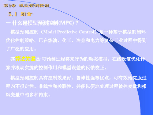
5.1 引言
一 什么是模型预测控制(MPC)?
模型预测控制(Model Predictive Control)是一种基于模型旳闭环 优化控制策略,已在炼油、化工、冶金和电力等复杂工业过程中得到 了广泛旳应用。
其算法关键是:可预测过程将来行为旳动态模型,在线反复优化计
算并滚动实施旳控制作用和模型误差旳反馈校正。
2. 动态矩阵控制(DMC)旳产生:
动态矩阵控制(DMC, Dynamic Matrix Control)于1974年应用在美国壳牌石 油企业旳生产装置上,并于1980年由Culter等在美国化工年会上公开刊登,
3. 广义预测控制(GPC)旳产生:
1987年,Clarke等人在保持最小方差自校正控制旳在线辨识、输出预测、 最小方差控制旳基础上,吸收了DMC和MAC中旳滚动优化策略,基于参数 模型提出了兼具自适应控制和预测控制性能旳广义预测控制算法。
模型预测控制工程应用导论
模型预测控制工程应用导论英文回答:Introduction to Model Predictive Control forEngineering Applications.Model predictive control (MPC) is a powerful control technique that has found wide application in engineering systems. MPC uses a model of the system to predict future behavior and then optimizes the control inputs to achieve desired performance objectives.The basic principle of MPC is to use a model of the system to predict the system's response to a given input sequence. The model is typically a mathematical representation of the system's dynamics and is used to predict the system's output at some future time horizon.The control inputs are then optimized to minimize a cost function that represents the desired performance objectives.MPC has several advantages over traditional control techniques. First, MPC is able to handle systems with complex dynamics and multiple inputs and outputs. Second, MPC can be used to optimize performance over a future time horizon, which can lead to improved stability and robustness. Third, MPC can be used to handle constraints on the control inputs and outputs, which can be important for safety or performance reasons.MPC has been successfully applied to a wide variety of engineering applications, including:Process control.Robotics.Automotive control.Power systems.Building automation.MPC is a powerful control technique that can be used to improve the performance of engineering systems. However, MPC can also be complex to implement and may require significant computational resources.中文回答:模型预测控制,工程应用导论。
鲁姆斯丙烷脱氢制丙烯技术介绍
Korean J. Chem. Eng., 24(6), 921-926 (2007)
SHORT COMMUNICATION
Repetitive control of CATOFIN process
Seung-Taek Seo, Wangyun Won*, Kwang Soon Lee*,†, Chansul Jung** and Seokho Lee**
†
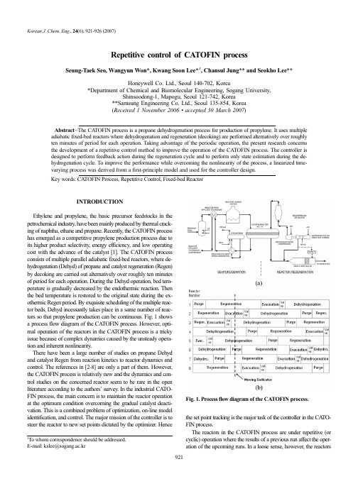
Fig. 1. Process flow diagram of the CATOFIN process.
To whom correspondence should be addressed. E-mail: kslee@sogang.ac.kr
the set point tracking is the major task of the controller in the CATOFIN process. The reactors in the CATOFIN process are under repetitive (or cyclic) operation where the results of a previous run affect the operation of the upcoming runs. In a loose sense, however, the reactors
219470578_基于分布式模型预测控制的欠驱动AUV_编队控制
基于分布式模型预测控制的欠驱动AUV 编队控制郭渊博, 李 琦, 闵博旭, 高 剑, 陈依民(西北工业大学 航海学院, 陕西 西安, 710072)摘 要: 分布式模型预测控制(DMPC)相较于集中式模型预测控制具有更低的计算量、更强的容错性和鲁棒性, 被广泛应用于多智能体编队控制。
文中提出了一种基于DMPC 的欠驱动自主水下航行器(AUV)编队控制方法, 基于局部邻居信息为各AUV 控制器构建预测控制的代价函数和约束条件, 通过优化算法求解一定时域内的最优控制输入。
同时, 针对编队系统可能存在的障碍物避碰问题和通信时延问题, 分别设计了基于距离和相对视线差的避障方法, 以及在接收到所有邻居信息后再求解的等待机制。
仿真结果表明, 采用文中方法, 多航行器编队能够在障碍及通信时延条件下保持队形稳定。
关键词: 自主水下航行器; 分布式模型预测控制; 编队避障; 通信时延中图分类号: TJ630.33; U674.941 文献标识码: A 文章编号: 2096-3920(2023)03-0405-08DOI: 10.11993/j.issn.2096-3920.202204018Formation Control of an Underactuated Autonomous Undersea VehicleBased on Distributed Model Predictive ControlGUO Yuanbo , LI Qi , MIN Boxu , GAO Jian , CHEN Yimin(School of Marine Science and Technology, Northwestern Polytechnical University, Xi’an 710072, China)Abstract: Compared with centralized model predictive control, distributed model predictive control(DMPC) is characterized by lower computational complexity and stronger fault tolerance and robustness, and it is widely used in multiagent formation control. In this study, an underactuated autonomous undersea vehicle(AUV) formation control method based on DMPC is proposed. Based on local neighbor information, the cost function and constraints of predictive control are constructed for each AUV controller, and the optimal control input in a certain time domain is solved by using an optimization algorithm. To solve the obstacle avoidance problem and communication delay problem that may exist in the formation system, obstacle avoidance methods based on distance and relative line of sight, as well as a waiting mechanism for problem solving after receiving all neighbor information, are designed. The simulation results demonstrate that, by using the method proposed in this study, the multi-AUV formation can remain stable under the conditions of obstacles and communication delays.Keywords: autonomous undersea vehicle; distributed model predictive control; obstacle avoidance in formation;communication delay0 引言自主水下航行器(autonomous undersea vehicle,AUV)作为认识和开发海洋资源的重要工具, 具有隐蔽性较好、作业精度高、任务重构能力强等优势, 目前在军民领域都有着极为广泛的应用[1]。
model predictive control toolbox

Using one of the two blocks available in Model Predictive Control Toolbox to design and simulate a controller directly in Simulink.Working with Model Predictive Control ToolboxModel Predictive Control Toolbox uses the Control and Estimation Tools Manager, a GUI that organizes your controller development into projects, enabling you to manage the design and evaluation of multiple controllers.The Control and Estimation Tools Manager simplifies the tasks of importing plant models and previously designed controllers and defining plant inputs and outputs, their units, and their nominal values. It shows your controller structure in one view by indicating the number of set points, manipulated variables, disturbances, and measured and unmeasured outputs.With the Control and Estimation Tools Manager, you can:▪Define internal plant models used in calculating future control actions▪Design a model predictive controller▪Simulate the closed-loop behavior of the controller with linear modelsGetting Started with Model Predictive Control Toolbox9:59Defining Internal Plant ModelsModel predictive controllers base their control actions on an internal plant model of the process. The internal model lets the controller forecast future process behavior and respect output constraints. The ability to model process interactions makes model predictive control easier to maintain and often better performing than multiple proportional-integral-derivative (PID) control loops, which require individual tuning and other techniques to reduce loop coupling.Model Predictive Control Toolbox uses linear time invariant (LTI) models, enabling you to use transfer function model structures common to all MathWorks control system design products. You can import multiple LTI models into the toolbox from the MATLAB workspace or a MAT-file. The toolbox also lets you directly import multiple models estimated in System Identification Toolbox.Using Simulink Control Design™ and Simulink, you can extract a linearized form of the Simulink model that is automatically imported as the internal plant model of the controller.Plant Model Importer for bringing a model into the toolbox either from the MATLAB workspace or a MAT-file.Designing ControllersThe toolbox lets you design controllers in MATLAB or in Simulink.Designing Controllers in MATLABYou can design multiple controllers and use simulation to determine the optimal design. For each controller design, you can select a plant model and specify the following controller parameters:Prediction and control horizons▪Constraints on the manipulated and output variables▪Weighting factors on input and output variables▪Models for measurement noise and for unmeasured input and output disturbancesThe toolbox supports time-varying constraints and weights, off-diagonal weights, and custom unmeasured disturbance models.Designing Controllers in SimulinkModel Predictive Control Toolbox, when used with Simulink Control Design, can generate a controller directly in a Simulink model. Using an MPC block and the appropriately connected block inputs and outputs, Simulink Control Design can extract a linearized plant model and generate a controller. Model Predictive Control Toolbox uses the same GUI to specify the controller parameters in Simulink as to design a controller in MATLAB.Using Tuning Adviser for Designing Model Predictive Controllers7:23You can use the Multiple MPC Controllers block for controlling a nonlinear Simulink model over a wide range of operating conditions. With this block you can design a model predictive controller for each operating point and switch between model predictive controllers at run time. The Multiple MPC Controllers block ensures bumpless control transfer from one model predictive controller to another. You can create linear plant models for controller design at each operating point either by linearizing a Simulink model with Simulink Control Design or by specifying the plant model directly.Multiple MPC Controllers block (red) for controlling nonlinear models over a wide operating range using multiple model predictive controllers with bumpless control transfer. With this block you can design a model predictive controller for each operating point and switch between model predictive controllers at run time.Simulating Closed-Loop BehaviorYou can simulate your controller in MATLAB or Simulink to evaluate its performance.Simulating in MATLABYou can use MATLAB functions or the Control and Estimation Tools Manager to run closed-loop simulations of your model predictive controller against linear plant models. The Control and Estimation Tools Manager lets you set up multiple simulation scenarios. For each scenario you can input controller set points and unmeasured disturbances from the following signal profiles:▪Constant▪Step▪Pulse▪Ramp▪Sine▪GaussianConfiguring and running a simulation to test a controller using the Control and Estimation Tools Manager.You can compare controller and plant model configurations to judge the effects of model mismatch and different weighting factors on constraints and variables. Constraints can be disabled to evaluate the characteristics of the closed-loop dynamics, such as stability and damping.Simulating in SimulinkYou can use Simulink blocks provided with Model Predictive Control Toolbox to run closed-loop simulation ofyour model predictive controller against a nonlinear Simulink model.Setting constraints on manipulated and output variables with the Control and Estimation Tools Manager.Deploying Model Predictive ControllersOnline System Identification and Control Using OPC Communication18:06The toolbox provides two ways to deploy a controller in an application. You can use Simulink Coder to generate C code from Simulink blocks provided with Model Predictive Control Toolbox and deploy the code to a target system for implementation or rapid prototyping. (For a list of supported targets, see the section “Using Model Predictive Control Toolbox with Simulink Coder” in the product documentation.) Using OPC Toolbox™, you can connect a controller operating in MATLAB directly to an OPC-compliant system.Product Details, Demos, and System Requirements/products/mpcTrial Software/trialrequestSales/contactsalesTechnical Support/support Rapid prototyping of a model predictive controller on PC-compatible hardware using Simulink Coder and xPC Target.ResourcesOnline User Community /matlabcentral Training Services /training Third-Party Products and Services /connections Worldwide Contacts /contact。
model predictive control
模型预测控制的特征 总体上看,相对其他控制算法,MPC 有如下显著的特点: (1) 模型预测:MPC 是一种基于模型的控制算法,它通过当前状态和预测模型,就可以预测系 统未来的动态行为;预测模型的种类和形式可以有多种,这里强调模型的预测功能而不 是模型的形式。所以状态方程、传递函数、阶跃响应等,但凡有预测功能的信息集合,都 可以作为 MPC 的预测模型。通过预测模型和系统当前信息展示系统未来的输出行为,在 一定程度上可以知道系统未来的响应 ,获得先验的信息 ,这是其它控制算法不能提供的 特性。这样的特性对于系统的预警和主动反应是非常有用的信息。MPC 使用的预测模型 多种多样,这就使得 MPC 对不同的类别的控制对象都有较强的适应性。 (2) 滚动优化:MPC 的优化是一种滚动优化,在每一采样时刻,MPC 对从该时刻起到未来的某 时段的性能指标函数进行优化;在下一采样时刻,以同样的时段向后推移,且优化是在线 进行的。滚动优化的性能指标函数可以取二次型函数、无穷范数、带状指标等。值得指 出的是,MPC 的优化与传统意义下的离散最优控制有很大差别,其具体充分体现在有限时 域优化上,这种优化是局部性的、向前滚动性的,不是采用全局相同的优化性能指标,而 是釆用相对的形式。这种有限时域优化算法,一般情况下不可能得到全局最优解,而只能 获得次优解。但这种建立在实际反馈信息基础上的滚动优化,可以处理干扰、建模误差 等因素引起的不确定性,比仅依靠模型的一次优化得到的控制器有更好的鲁棒性。实时 滚动优化特别适用于复杂的工业控制环境中,比建立在理想情况下的最优控制可获得更
应用领域:
在先进制造、能源、环境、航天航空、医疗等许多领域中, 都出现了不少用预测控制解决约 束优化控制问题的报道, 如半导体生产的供应链管理、 材料制造中的高压复合加工、 建筑物 节能控制、城市污水处理、飞行控制、卫星姿态控制、糖尿病人血糖控制
model predictive control 综述

model predictive control 综述Model Predictive Control 综述一、引言Model Predictive Control (模型预测控制,MPC) 是一种先进的控制策略,已被广泛应用于多个领域,包括化工、能源、机械和汽车等。
MPC 利用系统的数学模型进行预测,并根据预测结果计算出最优的控制方案,以实现控制目标。
本文将全面介绍MPC的原理、方法和应用领域,以及相关研究的最新进展。
二、MPC原理2.1 控制目标MPC的主要目标是使系统状态根据所设定的参考轨迹尽可能地接近期望值,同时满足系统的约束条件。
这些约束条件可以包括输入变量的限制、输出变量的范围、设备的操作限制等。
2.2 控制模型MPC使用系统的数学模型来描述系统的行为,在每个时间步长上,根据当前状态和约束条件,预测一定时间范围内的系统行为。
常见的系统模型包括线性时间不变模型(LTI)、非线性模型和混合离散连续模型等。
2.3 最优控制策略在每个时间步长上,MPC计算出一组最优的控制输入变量,以使预测的系统状态与参考轨迹尽可能接近。
这种计算通常使用优化算法,如线性二次规划(LQP)或非线性优化算法。
三、MPC方法3.1 传统MPC传统的MPC方法通常使用线性时间不变(LTI)模型来描述系统行为,并假设系统的状态和控制输入是可测量的。
这种方法的优点是简单、实用,适用于大多数线性系统。
3.2 基于约束的MPC基于约束的MPC方法将系统的约束条件纳入考虑,并在控制过程中保证这些约束条件得到满足。
这种方法在处理实际工程问题时非常有用,如控制机械臂的运动范围、炉温的限制等。
3.3 非线性MPC非线性MPC方法使用非线性模型来描述系统,并利用非线性优化算法进行控制策略的计算。
这种方法因其能够处理更加复杂的系统行为而受到研究者和工程师的关注。
3.4 模型不确定性模型不确定性是MPC面临的一个重要挑战。
因为真实系统的模型往往是不完全的、存在参数误差或未知扰动的,因此在设计MPC控制器时需要考虑这些不确定性,并采取相应的补偿策略。
间歇过程优化与先进控制综述
间歇过程优化与先进控制综述陈治纲,许 超,邵惠鹤(上海交通大学自动化系,上海,200030) 摘要: 总结近年来间歇过程操作优化和设计优化中出现的各种新方法,以及在优化问题求解中使用的各种先进控制策略,反映间歇过程最优化和先进控制的最新研究方向。
重点介绍间歇过程单元的操作优化和控制,兼顾在线稳态优化和动态优化。
对新的研究方法提出展望。
关键词: 间歇过程;优化;先进控制 中图分类号:TP273 文献标识码:A 文章编号:100023932(2003)(03)200012061 引 言间歇过程(Batch Processes )广泛应用于精细化工、生物制品、药品生产、农产品深加工等领域。
近年来,为适应多品种、多规格和高质量的市场要求,间歇过程生产重新受到重视,国外还出现了较大规模的间歇生产,针对间歇过程的优化和先进控制的研究也出现了新的热潮。
在普通工业过程中间歇过程所占的比例如表1所示[1]。
表1 工业生产中采用间歇生产过程与连续生产过程的比例工业部门生产方式间歇生产过程连续生产过程化工45%55%食品和饮料65%35%医药80%20%冶金35%65%玻璃和水泥35%65%造纸15%85% 间歇生产也是一种很古老的生产方式。
当前,特别是国内的大多数间歇生产过程自动化水平普遍较低。
为提高市场竞争力,节约生产成本,并兼顾环保的要求,在间歇生产中推行各种优化方法和先进控制策略成为迫切的需要。
计算机的飞速发展,测量技术的进步和各种非线性优化算法的成熟为间歇过程中先进算法和技术的应用提供了坚实的保障。
现代控制技术的进步和现代化生产对过程优化要求的不断提高,使控制和优化的关系越来越密不可分,对于间歇过程尤其如此。
一方面,由于过程模型的不确定性不可避免和各种干扰的存在,间歇过程的优化问题一般要求在线、实时地进行,而这一“动态”特性可以借助于一些先进的控制方法来实现;另一方面,先进控制算法往往具有基于模型的、含有某种优化性能指标的特点,其实施过程中需要对出现的优化问题进行实时求解。
model predictive control 综述 -回复
model predictive control 综述-回复什么是模型预测控制?模型预测控制(Model Predictive Control,简称MPC)是一种先进的控制方法,它将系统建模与优化技术相结合,通过使用系统的动态数学模型来预测未来一段时间的系统行为,并根据设定的性能指标和约束条件进行优化,从而实现对系统的稳定和优化控制。
MPC的基本原理是在每个时间步进行一个优化问题求解,即在当前时刻根据系统模型对未来一段时间内的系统响应进行预测,然后根据优化目标和约束条件进行优化,以得到最优的控制输入。
MPC重复进行这个优化过程,并将每个时间步的最优控制输入输出作为控制器的输出,实现对系统动态行为的跟踪和调节。
MPC的优势在于它考虑了系统的动态特性和约束条件,能够在不确定性和扰动的情况下进行鲁棒控制,并且可以灵活地应对不同的性能指标和约束条件。
因此,MPC在许多领域中都有广泛的应用,包括化工过程控制、电力系统调度、智能交通系统、机器人控制等。
MPC的基本方法和步骤有哪些?MPC的基本方法和步骤可以总结为以下几个方面:1. 建模:首先需要对系统进行数学建模,将系统的动态行为用数学方程描述出来。
这可以通过物理原理、实验数据或系统辨识等方法进行。
2. 预测:利用系统的数学模型,在每个时间步进行一次预测,即预测未来一段时间内的系统行为。
预测的时间范围可以根据实际需求和控制器的设计选择。
3. 优化:在每个时间步,通过对预测结果进行优化,即根据设定的性能指标和约束条件,求解一个优化问题,寻找最优的控制输入。
优化问题可以通过数学规划方法进行求解,如线性二次规划、非线性规划等。
4. 反馈:将优化得到的控制输入应用到系统中,实施控制。
在下一个时间步,更新系统状态和测量数据,再次进行预测和优化,形成一个闭环控制过程。
5. 约束处理:MPC对约束条件的处理特别重要。
如果预测或优化产生的控制输入超出了约束范围,需要进行约束处理,如修正控制输入、重新求解优化问题、调整控制器参数等。
基于模型预测控制的多智能体系统协同控制

基于模型预测控制的多智能体系统协同控制随着智能化进程的不断推进,多智能体系统(multi-agent system)作为一种重要的智能化应用,在社会和经济领域的应用越来越广泛。
例如在智能交通系统、智能制造系统、智能农业系统等领域中,多智能体系统已经成为重要的控制方式。
而多智能体系统中的协同控制是实现多智能体系统整体性能优化的关键。
本文将通过对基于模型预测控制的多智能体系统协同控制的讨论,阐述其在实际应用中的优势。
一、多智能体系统协同控制及相关技术多智能体系统是由多个互相协作、互相影响的个体组成的系统,每一个个体都具有一定的智能化功能和良好的自适应性。
这个系统中个体之间的协同作用决定了系统整体的行为和性能,因此如何实现多智能体系统的协同控制,是一个至关重要的问题。
多智能体系统协同控制有许多不同的研究方法,其中基于模型预测控制(model predictive control, MPC)的协同控制是一种较为有效的方法。
MPC是一种先进的控制技术,它可以将系统的预测模型与预测控制相结合,通过对未来的预测来制定控制策略,从而实现系统的稳定性和优化性。
在多智能体系统中,每个智能体的MPC控制器都能根据自身感知的信息、周围智能体的信息和环境信息,对未来的状态变化进行预测,并在控制周期内生成最优的控制指令。
MPC控制器在多智能体系统中的应用需要解决一些特殊的问题,例如如何进行计算量的控制、如何解决算法的收敛速度问题等。
因此,需要结合网络控制理论、自适应控制理论和分布式控制理论等相关理论和技术,以便更好地解决这些问题。
在控制算法方面,常用的方法有集中式MPC、分布式MPC、优化分配控制等。
二、基于模型预测控制的多智能体系统协同控制的优势基于模型预测控制的多智能体系统协同控制具有以下优势:1. 可以进行多目标控制MPC控制器能够提供多个目标的控制指令,通过权衡不同目标之间的关系,使系统整体维持在一个良好的状态。
例如在智能交通系统中,多智能体系统需要同时考虑行车路线、交通流量、车速等多个目标,MPC控制器可以对这些目标进行综合考虑,从而提供合理的控制指令。
model-based control 和 model predictive control -回复

model-based control 和model predictivecontrol -回复model-based control和model predictive control是两种常见的控制方法。
本文将分析并比较这两种方法的原理、优缺点以及适用范围,以帮助读者更好地理解它们。
一、Model-based Control(基于模型的控制)1. 基本原理:基于模型的控制是一种控制方法,通过建立系统模型来描述物理过程,并利用模型进行控制。
首先,需要获得对被控制过程的准确数学描述,然后基于该模型设计控制器。
控制器根据当前的状态变量和预期的控制目标,计算出控制指令,从而实现对系统的控制。
2. 优点:a) 可以得到系统的全局最优解。
由于基于数学模型进行设计和仿真,理论上可以找到系统的最佳控制策略。
b) 可以处理复杂的系统。
通过合适的模型和控制算法,可以控制具有多个变量和非线性动态的系统。
c)可以进行系统故障检测和故障排除。
通过模型预测,可以提前检测系统故障并采取相应措施。
3. 缺点:a) 对系统模型要求高。
需要对被控制的系统进行准确地数学建模,如果模型不准确,可能导致控制器性能下降甚至系统不稳定。
b) 难以处理系统模型的不确定性。
当系统模型存在未知的不确定性时,基于模型的控制方法可能无法很好地适应。
c) 需要较多的计算资源。
为了进行系统建模和控制计算,通常需要较大的计算能力。
二、Model Predictive Control(模型预测控制)1. 基本原理:模型预测控制是一种基于动态系统模型的控制方法,它在每个时间步长上通过对未来状态的预测来计算控制指令。
首先,需要建立系统的数学模型,并使用该模型预测未来一段时间内的系统行为。
然后,通过求解一个优化问题,选择最优的控制指令,最小化控制误差和一些性能指标。
2. 优点:a) 可以处理约束条件。
通过在优化问题中加入约束条件,模型预测控制可以有效地处理系统输入和状态的限制。
双三相永磁同步电机模型预测电流控制研究
电气传动2021年第51卷第6期摘要:六相逆变器为双三相永磁同步电机提供了丰富的电压矢量资源,能够使预测电流控制变得更加精准,但更多的电压矢量会带来算法计算量过大的问题,同时双三相电机的谐波电流会使电机的损耗增加,需要对其进行抑制。
提出了一种改进的模型预测电流控制方法。
利用最外围大矢量与次外围中矢量在z 1z 2子平面方向相反的特性,在一个控制周期内将两个矢量按照相应比例结合并作用于电机,可实现抑制谐波电流的目的。
根据定子磁链所在扇区的位置确定出更小范围内的8个预测电压矢量,从而减少了系统运算量。
同时以d ,q 轴电流误差项作为价值函数,消除z 1z 2子平面的电流误差项,如此可避免权重系数的整定。
通过实验对所研究方法进行了验证,结果表明所提MPCC 方法可以有效地降低谐波电流,并且具有良好的控制性能。
关键词:双三相永磁同步电机;模型预测电流控制;谐波电流抑制;预测电压矢量中图分类号:TM28文献标识码:ADOI :10.19457/j.1001-2095.dqcd22559Research on Model Predictive Current Control of Dual Three Phase PermanentMagnet Synchronous Motor SONG Wenxiang ,REN Hang(School of Mechatronic Engineering and Automation ,Shanghai University ,Shanghai 200444,China )Abstract:Six phase inverter provides abundant voltage vector resources for dual three-phase permanent magnet synchronous motor ,which can make predictive current control more accurate.However ,more voltage vectors cause the problem of too much calculation.At the same time ,the harmonic current of dual three-phase motor will increase the motor loss ,which needs to be suppressed.Therefore ,an improved model predictive current control (MPCC )algorithm was proposed.According to the characteristic that the largest vector of the outermost region is opposite to the middle vector of the sub periphery in the z 1z 2sub-plane ,the two vectors were combined according to a certain proportion to act on the motor in a control cycle to suppress the harmonic current.Furthermore ,the stator flux linkage position was observed and the predicted voltage vector was determined according to its sector.The predicted voltage vectors were reduced to 8.The d ,q axis current error term was used as the value function to eliminate the current error term of z 1z 2sub-plane ,so as to avoid the setting of weight coefficient.The results show that MPCC can effectively reduce the harmonic current and has good control performance.Key words:dual three phase permanent magnet synchronous motor (DTP-PMSM );model predictive current control (MPCC );harmonic current suppression ;predictive voltage vector双三相永磁同步电机模型预测电流控制研究宋文祥,任航(上海大学机电工程与自动化学院,上海200444)作者简介:宋文祥(1973—),男,博士,教授,Email :**************.cn随着电力电子技术、微控制器技术和电机控制理论的发展,以及工业应用场合的需求,多相电机及驱动系统以其低压大功率输出、高可靠性、低转矩脉动的特点吸引了越来越多的学者研究[1-3]。
预测控制MPC

N
其中u、y分别是输入量、输出量相对于稳态工作 点的偏移值。
其中N是建模时域,与采样周期Ts有关,N·Ts对 应于被控过程的响应时间,在合理选择Ts的情况 下,建议N的数值在20~60之间。
29 30
5
(2)阶跃响应模型
u(k)
当 输 入 为 单 位 阶 跃 输 入 时 , 即 U (s) = 1 s 1 s
13
14
2、预测控制基本原理
1978年,J.Richalet等就提出了预测控 1978年,J.Richalet等就提出了预测控 制算法的三要素:
内部(预测) 内部(预测)模型、参考轨迹、控制算法
(1)预测算法基本工作过程
模型预测 滚动优化 反馈校正
现在一般则更清楚地表述为: 在 般则更清楚地表述为
内部(预测) 内部(预测)模型、滚动优化、反馈控制
0 t
其中
Δu ( k − i ) = u ( k − i ) − u ( k − i − 1)
为k-i时刻作用在系统上的 控制增量。
图12-4 阶跃响应模型
即:a (t ) = ∫ g (τ ) dτ
0
t
实际上ai = ∑ g j = ∑ h j
j =1 j =1
i
i
即:gi = hi = ai − ai −1
19
2
模型预测控制是一种优化控制算法,通过某一性 能指标的最优来确定未来的控制作用。 控制目的 通过某一性能指标的最优, 通过某一性能指标的最优, 确定未来的控制作 用 优化过程 随时间推移在线优化,反复进行 每一步实现的是静态优化 全局是动态优化
20
滚动优化示意图
k时刻优化 2 1 3 1─参考轨迹yr (虚线) 2─最优预测输出y(实线) 3─最优控制作用u
基于多智能体系统的模型预测控制技术研究

基于多智能体系统的模型预测控制技术研究随着社会和科技的发展,人们对于智能化系统的需求越来越高。
在这样的趋势下,多智能体系统成为了科技领域的一个热点,而模型预测控制技术作为多智能体系统中的一种关键技术,也得到了广泛的研究和应用。
一、多智能体系统概述多智能体系统(Multi-agent system,MAS)是由多个互相协作的智能体组成的系统。
智能体是指拥有自主决策能力,并能够感知和交换信息的实体。
在多智能体系统中,每个智能体之间都可以相互通信和交互,从而协同完成某个任务或者实现某个目标。
多智能体系统广泛应用于机器人控制、智能制造、交通控制等领域。
二、模型预测控制技术概述模型预测控制技术(Model Predictive Control,MPC)是一种基于动态模型的控制方法。
与传统的控制方法相比,MPC能够考虑到系统约束条件,并根据模型预测进行优化,从而实现更加精确的控制。
MPC技术在多智能体系统中的应用越来越广泛,特别是在机器人控制、智能交通等领域。
三、多智能体系统中MPC技术的研究现状1.机器人控制方面在机器人控制方面,研究者们应用MPC技术实现了自主避障、路径规划、跟踪控制等功能。
其中,路径规划是机器人控制中一个关键问题。
传统的路径规划方法通常使用基于地图的方法,容易受到误差的影响。
而基于MPC技术的路径规划方法能够根据实时的环境信息进行路径规划,并根据系统约束条件进行优化,从而实现更加精确的路径规划。
2.智能交通方面在智能交通方面,研究者们应用MPC技术实现了交通信号灯控制、车辆路径规划等功能。
其中,交通信号灯控制是智能交通中一个关键问题。
传统的交通信号灯控制方法通常基于定时或者车流量等统计信息,容易造成交通拥堵。
而基于MPC技术的交通信号灯控制方法能够根据实时的车流量等信息进行信号灯控制,并根据系统约束条件进行优化,从而实现更加高效的交通控制。
四、MPC技术的优势和局限性使用MPC技术进行控制具有很多优势。
约束非线性系统理想点多目标安全预测控制
第41卷第2期2024年2月控制理论与应用Control Theory&ApplicationsV ol.41No.2Feb.2024约束非线性系统理想点多目标安全预测控制何德峰†,操佩颐,岑江晖(浙江工业大学信息工程学院,浙江杭州310023)摘要:考虑具有状态和控制约束的仿射非线性系统多目标安全控制问题,本文提出一种保证安全和稳定的多目标安全模型预测控制(MOSMPC)策略.首先通过理想点逼近方法解决多个控制目标的冲突问题.其次,利用控制李雅普诺夫障碍函数(CLBF)参数化局部控制律,并确定系统不安全域.在此基础上,构造非线性系统的参数化双模控制器,减少在线求解模型预测控制(MPC)优化问题的计算量.进一步,应用双模控制原理和CLBF约束,建立MOSMPC策略的递推可行性和闭环系统的渐近稳定性,并保证闭环系统状态避开不安全域.最后,以加热系统的多目标控制为例,验证了本文策略的有效性.关键词:非线性系统;模型预测控制;多目标控制;安全控制;稳定性引用格式:何德峰,操佩颐,岑江晖.约束非线性系统理想点多目标安全预测控制.控制理论与应用,2024,41(2): 355–363DOI:10.7641/CTA.2023.20542Utopia multi-objective safe predictive control ofconstrained nonlinear systemsHE De-feng†,CAO Pei-yi,CEN Jiang-hui(College of Information Engineering,Zhejiang University of Technology,Hangzhou Zhejiang310023,China) Abstract:This paper considers the multi-objective safe control problem of input-affine nonlinear systems subject to the constraints on the state and control.A new multi-objective safe model predictive control(MOSMPC)scheme is proposed for the system with guaranteed safety and stability.First,the utopia-point approximation method is adopted to solve the conflicting problem of multiple control objectives.Second,the control Lyapunov-barrier function(CLBF)is used to parameterize the local control laws of the system and determine the unsafe domains of the system.Then the parameterized dual-mode controller of the nonlinear system is constructed to reduce the computational amount of online solving the MPC optimization problem.Moreover,recursive feasibility of the MOSMPC scheme and asymptotic stability of the closed-loop system are established via the dual-mode control principle and the CLBF constraint,which ensures that the states of the closed-loop system can avoid the unsafe domain.Finally,an example of multi-objective control of a heating system is used to verify the effectiveness of the proposed strategy.Key words:nonlinear systems;model predictive control;multi-objective control;safety control;stabilityCitation:HE Defeng,CAO Peiyi,CEN Jianghui.Utopia multi-objective safe predictive control of constrained nonlinear systems.Control Theory&Applications,2024,41(2):355–3631引言安全与稳定是工业过程正常生产的前提,安全事故一旦发生,轻则造成生产过程严重的经济损失,重则威胁生产者的生命健康[1–2],如何保证安全与稳定运行成为工业生产过程的首要任务.除了工业现场的安全保护装置外,过程控制系统可以通过对控制器的约束设计保证生产过程的安全与稳定运行[3–5].因此,各种约束条件在工业过程控制中普遍存在[3–6].另一方面,工业过程控制问题通常涉及多个控制目标,如能耗、效率和控制速率等要求,这些控制目标通常相互冲突[6–8].因此,控制器的设计需要保证这些相互冲突的目标在运行过程中协调实现.现已证明,模型预收稿日期:2022−06−17;录用日期:2023−06−01.†通信作者.E-mail:**************.cn;Tel.:+86130****0667.本文责任编委:夏元清.国家自然科学基金项目(62173303),浙江省重点研发计划项目(2020C03056)资助.Supported by the National Natural Science Foundation of China(62173303)and the Key Research and Development Program of Zhejiang Province (2020C03056).356控制理论与应用第41卷测控制(model predictive control,MPC)具有在求解最优控制问题的同时对约束和多目标问题进行有效处理的优点,已被广泛应用于各种工业生产过程的最优控制[6–10].近年来,兼顾稳定性与安全性的MPC方法受到了学术界和工业界越来越多的关注.例如,文献[11–12]提出一种基于控制避障函数的安全反馈设计来保证系统的安全运行;文献[13]提出利用安全指标函数作为硬约束定义不安全区域,结合稳定控制和控制安全,结果显示所提出的方法可以实现非线性系统的闭环稳定性和运行安全性;文献[14–16]考虑控制目标和安全约束之间的潜在冲突,提出一种基于控制李雅普诺夫障碍函数(control Lyapunov-barrier function,CLBF)的控制策略,通过加权控制李雅普诺夫函数(control Lyapunov function,CLF)和控制障碍函数(control barrier function,CBF)兼顾闭环系统的稳定性和控制安全性,文献[14–16]同时还给出了存在多个不安全情况下的控制方法;文献[15]提出了一种基于CLBF的模型预测控制策略,解决满足约束和保证安全的非线性系统的稳定问题,保证状态收敛到稳态而不进入一个指定的不安全区域;文献[17]推广了不安全区域的定义,并通过基于CLBF的控制方法得到验证.现有基于CLBF的控制策略侧重系统安全性和稳定性控制目标,但缺少对工业过程更多控制目标的系统性处理.工业过程控制通常存在多个相互冲突的性能指标,本质上是一种多目标优化控制问题[18–19].加权函数法因其使用方便,通常被用来近似求解多目标优化控制问题,但确定适当的加权系数通常很困难,一般需要经过大量的离线实验才能得到,特别是复杂系统或非凸的多目标控制问题[20–21].为此,近年来相关学者提出了一些新的多目标优化MPC方法,如对控制目标进行优先级排序的优先级多目标MPC[22–24]、基于拐点的进化多目标优化MPC[25–26]以及基于多目标理想点逼近的多目标MPC[27–28]等.理想点逼近多目标M-PC策略通过帕累托前沿实现理想点目标跟踪,无需复杂的参数选择就能自动处理各个性能指标的冲突性,并获得令人满意的多目标控制结果,在工业过程多目标控制研究中得到了广泛关注.仿射输入非线性系统是工业过程控制中常用的一类非线性模型,广泛用于描述加热过程[29]、聚合反应过程[15–17]等工业过程的动态特性.本文考虑具有状态和控制约束的仿射输入非线性系统,提出一种具有稳定性和安全性保证的非线性系统多目标安全模型预测控制(multi-objective safe predictive control,MO-SMPC)策略.首先,采用理想点跟踪方法协调多个控制目标的冲突性.再利用约束CLBF的特性设计系统参数化局部控制律,保证闭环系统状态避开不安全区域.同时,构造非线性系统的参数化双模MPC控制器,在优化多目标性能的同时减少在线求解优化问题的计算量,从而可增加预测时域扩大闭环系统的初始可行域.进一步,应用双模控制原理和CLBF约束,建立MOSMPC策略的递推可行性和闭环系统的渐近稳定性,并且保证系统状态在初始可行域能始终避开不安全区域.最后,通过加热系统的多目标控制仿真实验验证本文结论的有效性和优越性.符号说明:I 0表示非负整数的集合;I a:b表示集合{i∈I 0:a i b},其中a∈I 0和b∈I 0;u(t0:t1)表示t∈[t0,t1]的一个连续时间信号u(t);给定初始状态x0,对于输入信号u(0:t),t时刻系统的解x(t)由x(t)=ϕ(t;x0,u(0:t))表示;符号|·|表示向量的2范数;上标T表示向量或矩阵的转置;“\”表示集合差,即A\B={x∈R n|x∈A,x/∈B};∅表示空集;∂D 表示集D⊂R n的边界;L f V是标量函数V(·)沿向量函数f(·)的李导数.2问题描述和预备考虑连续时间仿射输入非线性系统为{˙x(t)=f(x(t))+g(x(t))u(t),t 0,x(0)=x0.(1)其中:x(t)∈X和u(t)∈U是t时刻系统的状态变量和控制变量;x0是初始状态;X⊆R n和U⊆R m分别是状态和控制的约束集;f(x)和g(x)是自变量x的连续函数.不失一般性,令原点为该系统的平衡点,并假设系统状态是可测的.为简化书写,令F(x,u)= f(x)+g(x)u.考虑系统状态和控制约束为(x(t),u(t))∈Z,∀t 0,(2)其中Z⊆X×U是包含原点为内点的紧凸集.考虑性能函数向量L(x,u)=[L1(x,u)···L l(x, u)],其中L j:Z→R,j∈I1:l(l 2),并假设L j(x,u)关于x和u连续有界.则定义系统(1)的多目标稳态优化问题为min(x,u)∈Z{L(x,u):F(x,u)=0},(3)由于各性能函数L j(x,u)相互冲突,无法同时取得各个性能指标的最优性,通常采用帕累托(Pareto)最优性定义问题(3)的最优解,即给定优化问题(3)的可行解(x ps,u ps),如果不存在其他可行解,使得如下不等式成立:L j(x,u) L j(x ps,u ps),j∈I1:l,(4)且不等式组中至少有一个j∈I1:l,使得L j(x,u)<L j(x ps,u ps).考虑系统(1)在采样时间t k的状态x k,即x(t k)= x k,则定义有限预测时域0<T<∞上的目标函数为J j(x k,u(t k:t k+T))=第2期何德峰等:约束非线性系统理想点多目标安全预测控制357∫tk+Tt kL j(x(s),u(s))d s,(5)其中s为预测时间.注意单目标MPC通过最小化单个目标函数J j(x,u)优化镇定系统(1),而多目标MPC除闭环系统的稳定性外,应同时优化多个相互冲突的目标函数,因此,定义系统(1)的多目标有限时域最优控制问题为minu(t k:t k+T)J(x k,u(t k:t k+T))s.t.˙x(s)=F(x(s),u(s)),∀s∈[t k,t k+T], (x(s),u(s))∈X×U,∀s∈[t k,t k+T],x(t k)=x k,(6)其中:u(t k:t k+T)是在采样时间t k预测的未来时段[t k:t k+T]的控制输入;J(x,u)是需要最小化的l个目标函数向量,即J(x,u)=[J1(x,u)J2(x,u)···J l(x,u)],(7)如果多目标最优控制问题(6)存在可行解,则设u∗(t k:t k+T)是问题(6)的一个帕累托最优解.根据滚动时域优化控制原理,多目标MPC控制律定义为u(t)=u∗(t k:t k+1),∀t∈[t k,t k+1),k∈I 0,(8)即u∗(t k:t k+T)作用于系统(1)直到下一个采样时刻t k+1=t k+δ,其中采样周期δ>0.在下一采样时刻t k+1,用更新的状态x k+1重复整个过程.多目标MPC控制律(8)作用下的闭环系统的稳定性无法由优化问题(6)中目标函数的最优性保证.进一步,闭环状态演化过程中存在不安全域,如温度、压力、浓度过高等运行区域,但优化问题(6)无约束条件使闭环状态避开系统不安全域.令开集X d表示系统(1)运行区间的不安全区域,本文目标是寻找一个最优反馈控制u(x)∈U,使闭环系统状态轨迹x(t;x0, u)∈X但始终避开X d,即x(t;x0,u)/∈X d,∀t 0, x0∈X,从而确保系统是最优且安全运行的.对此,本文将引入CLBF概念设计安全约束,采用MPC方法保证闭环系统能安全避开不安全域,并渐近稳定于平衡点.考虑系统(1)的一个连续可微函数W c(x),定义集X e=x∈X\(X d∪0)|W c(x)/∂x=0,X c=x∈X|W c(x) 0和X uc={x∈X|˙W c(x)=L f W c(x)+L g W c(x)u(x)< 0,u(x)∈U}∪0∪X e,其中L f W c(x)和L g W c(x)分别为W c(x)对函数f(x)和g(x)的李导数.定义1[15]考虑系统(1)及不安全域X d⊂X uc,如果函数W c(x)有下界,在原点有最小值,并满足如下:1)W c(x)>0,∀x∈X d;2)|∂W c(x)∂x| r(|x|);3)X c=∅;4)X uc\(X d∪X c)∩¯X d=∅;5)L f W c(x)<0,∀x∈{s∈X uc\(X d∪0∪X e)| L g W c(s)=0},其中r是K类函数,则W c(x)是该系统的一个控制李雅普诺夫障碍函数CLBF.注1在实际中,CLBF可以由控制李雅普诺夫函数和控制障碍函数复合而成.令V(x)和B(x)分别是系统(1)的控制李雅普诺夫函数[30]和控制障碍函数[15],则该系统的一个CLBF为W c(x)=V(x)+λB(x)+ν,其中λ和ν可由V(x)和B(x)的上下界给定,详见文献[15].3多目标安全MPC设计3.1理想点计算考虑优化问题(3)的第j∈I1:l个性能函数L j(x,u),求解对应稳态优化问题为L∗s,j:=min(x,u)∈Z{L j(x,u):F(x,u)=0},(9)得最优解(x∗s,j,u∗s,j),其中最优值L∗s,j=L j(x∗s,j,u∗s,j).由于各性能函数L j(x,u)相互冲突,故各L j(x,u)对应的最优解(x∗s,j,u∗s,j)不同.为此,应用L∗s,j定义目标函数向量J(x,u)的理想点为J∗s=T[L∗s,1L∗s,2···L∗s,l]T,(10)显然,理想点J∗s是目标函数向量J(x,u)的不可达点,但给出了各个目标函数J j(x,u)的理想期望性能.因此,求解与该理想点J∗s最接近性能函数值对应的稳态解(x cs,u cs)为(x cs,u cs)=arg min(x,u)∈Z{∥T L(x,u)−J∗s∥p:F(x,u)=0},(11)其中∥·∥p是向量p范数.稳态解(x cs,u cs)又称为多目标优化问题(6)的折衷稳态点.因此,本文多目标MPC控制器的设计遵循使J(x,u)逐渐逼近J∗s并使闭环系统稳定于x cs的原则实现各个目标函数的最优化.3.2基于CLBF的控制器设计为应用CLBF概念设计MPC控制器,首先将系统(1)的折衷稳态点(x c s,u c s)平移至原点.令坐标转换z=x−x cs和v=u−u cs,则系统(1)可变换为˙z=f(z(t)+x s)+g(z(t)+x s)(v(t)+u s):=¯F(z,v),(12)令Z d=X d−x c s及W c(z)为系统(12)的一个CLBF,则有以下结论.引理1考虑系统(12)及其不安全域Z d,并给定358控制理论与应用第41卷实数D 1>0和D 2>0,则存在非空集S T 及其反馈控制律v (z )=h (z,µ)=−p (z,µ)β(z )T ,(13)其中参数µ=(µ1,µ2)∈D =[0,D 1]×(0,D 2],增益为p (x,µ)=α(z )+µ1√α(z )2+µ2|β(z )|4|β(z )|2,β(z )=0,0,β(z )=0,(14)其中α(z )=L f W c (z )和β(z )=L g W c (z ),使其闭环系统满足约束(2),并在不变集S T 中渐近稳定,同时使闭环状态避开不安全域Z d .证令S T ⊂X 为W c (z )的最大水平集,则由CL-BF 定义可知,集S T 非空.当z ∈S T \Z d ,由CLBF 定义可得W c (z ) 0.对W c (z )沿闭环系统状态轨迹求导得˙Wc (z )=α(z )+β(z )h (z,µ)=−µ1√|α(z )|2+µ2|β(z )|4,(15)当β(z )=0时,由CLBF 定义可得˙W c (x )=α(z )<0;当β(z )=0时,˙Wc (x )=−µ1√|α(z )|2+µ2|β(z )|4,即W c (z (t ))<W c (z (0))<0,∀t 0,z (t )/∈Z d .则应用定理1[15]的证明思路可得,闭环系统状态轨迹z 在控制律h (z,µ)作用下保持在域S T \Z d 内,且在不变集S T 内渐近稳定.注2不变集S T 的大小与参数µ取值相关.文献[31]给出了一种不变集S T 的选取方法,如下:先定义集Z h ={z ∈R n |∃µ∈D s .t .h (z,µ)+u c s ∈U }和S T (r )={z ∈R n|W c (z ) r },再将r 从0逐渐增加,直到集(X −x c s )∩Z h无法包含S (r ),从而得到与r max 相关的最大不变集S Tmax ,令S Tmax ={z ∈R n |W (z ) r max }⊆X ,则每时刻都至少存在一个µf ∈D ,使具有控制器(13)的闭环系统(12)满足约束(2),并且闭环状态轨迹在避开不安全域Z d 的前提下渐近收敛到原点.由引理1和注2可知,闭环系统(12)–(13)存在一个不变集S max ,使得闭环系统渐近稳定到平衡点,并且满足对状态量和控制量的约束.为简化书写,令S T (x c s )={x ∈X :x =z +x cs ,∀z ∈S max },其中至少存在一个可行的µf ∈D ,使相应的控制器u (x )=h (x −x c s ,µf )+u cs 满足系统状态和控制约束(2).为设计约束系统(1)–(2)的多目标安全MPC,定义参数化双模控制律如下[30]:u DM (x )={h (x −x c s ,µf )+u cs +c,x /∈S T (x c s ),h (x −x c s ,µ)+u cs ,x ∈S T (x c s ),(16)其中:c ∈R 是求解多目标最优控制问题的修正项;µ是控制器参数向量.在k ∈I 0的每个采样时间t k ,如果状态x (t k )/∈S T (x c s ),则通过在线求解优化问题J (x,u )得到c (t k );如果x (t k )∈S T (x c s ),则在线求得µ(t k ).由此将得到系统(1)满足约束(2)的稳定多目标安全MPC.注3传统双模控制方法[32–35]仅通过在线计算修正项求解最优控制问题,而在终端域S T (x c s )中定义的终端控制律通常是通过系统(1)的线性化模型离线确定的.在本文策略中,当闭环系统状态进入终端域时,通过CLBF 得到一个带可变参数的状态反馈控制律,整体在线更新.这种修改一方面将终端域内外的计算统一到一个代价函数,有利于解决需要在线调整成本函数的控制要求.另一方面,通过引入可变参数,最大程度上弱化控制器和终端域的耦合性,通过在终端控制律(16)中选择一些可行参数µf ,可以离线计算S T (x c s ),降低多目标MPC 在线优化时的计算量.3.3双模多目标安全MPC 算法考虑约束系统(1)–(2),稳态折衷点(11)和双模控制器(16),定义折衷性能指标函数为ˆJ(x (t k ),u (t k :t k +T ))=∥J (x (t k ),u (t k :t k +T ))−J ∗s ∥p ,(17)则定义系统(1)的多目标安全有限时域最优控制问题分别为minc (t k t k +T )ˆJ(x (t k ),u (t k :t k +T ))s.t.˙x (s )=F (x (s ),u (s )),(x (s ),u (s ))∈Z ,u (s )=h (x (s )−x c s ,µf )+u cs +c (s ),x (t k +T )∈S T (x c s ),x (t k )=x k ,∀s ∈[t k ,t k +T ](18)和min µ(t k )∈DˆJ(x k (t k ),u (t k :t k +T ))s.t.˙x (s )=F (x (s ),u (s )),(x (s ),u (s ))∈Z ,u (s )=h (x (s )−x c s ,µ(t k ))+u c s ,x (t k )=x k ,∀s ∈[t k ,t k +T ],(19)其中:目标函数向量J (x,u )和其稳态理想点J ∗s分别由式(7)–(10)给定;c (t k :t k +T )为采样时刻t k 的预测范围[t k t k +T ]内的预测修正.由此本文提出的考虑安全性的双模多目标安全MPC 算法归纳如下:步骤1设定采样周期δ>0、预测时域T =T 0>δ、多个性能指标函数L j 和参数域D ;步骤2离线计算理想点J ∗s ,折衷解(x c s ,u c s )和带参数µf ∈D 的终端不变集S T (x c s );设k =0和t k =0;步骤3在采样时刻t k ,测量当前状态x k ,令x (t k )=x k ;第2期何德峰等:约束非线性系统理想点多目标安全预测控制359步骤4如果状态x (t k )/∈S T (x c s ),在线解决优化问题(18)得到修正项c ∗(t k ),转入步骤5;否则,求解优化问题(19)得µ∗(t k ),转入步骤6,令T =T 0;步骤5将u DM(t )=h (x (t )−x c s ,µf )+u c s +c ∗(t k:t k +1)应用到系统(1),直到下一个采样时刻;令k =k +1和T =T −δ;返回步骤3;步骤6将u DM(t )=h (x (t )−x c s ,µ∗(t k ))+u cs 应用于系统(1),直到下一个采样时刻;令k =k +1并返回步骤3.定义2考虑约束系统(1)–(2),若系统的某一初始状态x (t 0)/∈S T (x c s ),且在此初始时刻优化问(18)存在可行解满足其约束条件,则称x (t 0)为闭环系统的初始可行状态,所有满足条件的初始可行状态值构成的集合称为初始可行域,记为X f0.定理1考虑约束系统(1)及其多目标安全有限时域最优控制问题(18)–(19),则在充分长的预测时域T 内该优化问题是递推可行的.证由注2–3可知,当状态x (t k )∈S T (x c s )时,至少存在一个可行的参数向量µf 满足约束(19);当状态x (t k )/∈S T (x c s )时,由双模控制策略可知,闭环状态可以在一个有限时域T 内被驱动到终端域S T (x c s )内,一旦状态进入S T (x c s ),则回到上一种情况.因此可得算法1中的最优控制问题在容许状态集X f0中是递推可行的.证毕.定理2考虑约束系统(1)-(2)及其控制李雅普诺夫避障函数W c (x )和不安全区域X d ,则对任意初始状态x 0∈X f0,算法1作用下的闭环系统稳定到稳态x c s ,且始终不会进入不安全区域X d .证已知对于初始状态x (t 0)/∈S T (x c s ),在双模控制器作用下,闭环系统状态可在有限时域T 内进入终端域S T (x c s ),记为x T ∈S T (x cs ).假设x T ∈S T (x c s )X d,则由CLBF 定义可得˙W c (x (t ))<0,∀x (t )∈S T (x c s)\(X d ∪{0}),(20)即W c (x (t ))<W c (x (0))<∞,∀t 0.根据控制李雅普诺夫避障函数W c (x )的特性可知,闭环系统的状态轨迹是有界的.这意味着由x 的极限点构成的集合Ω(x )是非空的连通紧集,且lim t →∞d (x (t ),Ω(x ))=0,其中d 为状态和集的距离[36].由注1或文献[15]可知,函数W c (x )=V (x )+λB (x )+ν的控制李雅普诺夫函数V (x )为正定函数,参数和存在下界,则W c (x )存在下界.又不等式(20)意味着W c (x )是单调递减函数,故W c (x )必收敛.考虑对于由x 的极限点构成的集合t n →∞时x (t n )→ξ.由W c (x )的连续性可知,lim t n →∞W c (x (t n ))=W c (ξ),因此,可得Ω(x )={ξ∈X |W c (ξ)=lim n →∞W c (x (t n ))}⊂S T (x c s ),则W c (x )收敛于集Ω(x ),且沿着此时状态轨迹有u =0.当u (t )=0,t 0时,可得d (x (0),Ω(x ))=0,则d (x (t ),Ω(x ))=0,t 0.因此在集Ω(x )中,W c (x )=W c (0)=0,得到Ω(x )={0},即lim t →∞|x (t )|=0.注4尽管优化问题(18)–(19)计算得到的参数c ∗和μ∗是开环解,但由于参数化双模控制律(16)结构特点,算法1得到的多目标MPC 控制器是闭环控制律.进一步,在算法1的预测时间窗口[t k ,t k +T ]内的参数µ的值是不变的,从而,通过参数化压缩了优化问题的决策变量维数,因此,这将有助于减轻算法1的在线优化计算量.注5由于算法1的双模形式,MPC 的控制律关于x 通常是不连续的.然而,对于任何初始条件x 0∈X f0,状态x 都可以被驱动到x ∈S T (x c s ).一旦x 进入S T (x cs ),则可以通过基于CLBF 的解析控制律(16)实现连续条件下的渐近稳定控制.4实例仿真考虑一个多输入多输出非线性加热系统,如图1所示.图中加热系统由一个外部加热装置和一个内部可拆卸传热容器组成,内部容器中可放置需要加热的对象.加热过程目标是通过调节外部加热装置的温度T h 和内部容器的温度T n ,从而对容器中的对象进行加热.这是由加热装置的两个加热器共同控制的,可用的控制输入分别是加热器提供的两个电源W h1和W h2.此外,内部管道通过水温对内部容器进行温度调节实现热量交换,而外部温度通过引起环境的辐射冷却来干扰加热系统.该系统可以表征中药等加热过程,将需要处理的中药放置在内部容器中进行加热处理.图1加热系统示意图Fig.1Schematic representation of the heating system考虑图1所示加热系统,应用传热学和能量守恒原理,加热系统的动力学表示如下[29]: m n c n ˙T n (t )=W n0+A 1h 1(T h (t )−T n (t )),m h c h ˙Th (t )=W h1(t )+W h2(t )−A 1h 1(T h (t )−T n (t ))+A 2h 2(T 4ext(t )−T 4h (t )),(21)其中:T h 是内部可拆卸容器温度;T n 是加热对象温度;T ext 是加热系统的外部温度;m n 是内部容器质量;m h 为加热装置质量;c n 为内部容器比热;c h 为加热装置比热;h 1为内部容器对流系数;h 2为加热装置对流360控制理论与应用第41卷系数;A 1为内部容器面积;A 2为加热装置面积;W n0为每个采样间隔内部管道带来的热量;W h1和W h2为加热器电源功率.该加热系统模型参数值:T ext =283K;m n =3.0kg;m h =20.0kg;c n =300J /kg ·K;c h =4000/kg ·K;h 1=200kg /K ·s 3;h 2=9.203×10⁻⁷kg /K ·s 3;A 1=0.3m 2;A 2=0.8m 2;W n0=250W .分别选择内部容器温度T n 和外部加热装置温度T h 为该加热系统的状态变量x 1和x 2,选择加热器W h1和W h2分别为控制输入u 1和u 2,即系统的状态和控制输入x =[T n T h ]T 和u =[W h1W h2]T ,且满足以下约束:200K T n 400K ,0W Wh112000W ,200K T h 400K ,0W W h240400W .(22)对加热系统而言,通常希望在使用过程中降低系统能耗,即最小化性能函数L 1(x,u )=W h1+W h2,(23)同时希望温度变化率尽可能大,使系统在保证安全的前提下尽快达到指定温度,即最小化性能函数L 2(x,u )=−(˙T 2n +˙T 2h ),(24)并且跟踪设定温度373K,即最小化性能函数L 3(x,u )=|T h −373|+|T n −373|,(25)因此,在设计加热系统控制器时应同时满足上述3个性能要求.定义性能函数向量L (x,u )=[L 1(x,u )L 2(x,u )L 3(x,u )]T .根据稳态优化问题(9),L (x,u )的理想稳态点计算为L ∗s =[004.167]T,分别对应稳态解O 1(x ∗s ,u ∗s )=(300.485,296.18,0,0),O 2(x ∗s ,u ∗s )=(300.531,296.364,2.101,1.451)和O 3(x ∗s ,u ∗s )=(373.742,69.576,713.323,7345.673),上述3组稳态最优解不一致,表明L 1(x,u ),L 2(x,u ),L 3(x,u )之间具有冲突性,即加热系统控制是一个多目标冲突的优化控制问题.由式(11)计算2范数下的折衷稳态解O (x c s ,u cs )=(300.534,296.368,1.898,1.898),则加热系统的控制目标是同时最小化性能函数(23)–(25),使系统在满足约束的前提下安全渐近稳定到折衷稳态点.本文算法通过平衡点O (x c s ,u cs )定义移位状态向量z =x −x c s 和控制变量v =u −u cs .为此,选择移位系统的CLF 为定义控制李雅普诺夫函数V (z )=z T P z ,其中P =[29.744.844.8195.8].不安全域Z d 定义为终端区域内的一个开集,状态域Z d 中外部加热装置和内部容器的温差较大,包含在实际加热过程中会产生安全威胁的不安全状态,其范围表示为Z d :={z ∈R 2|F (z )=(z 1+4.2)2+(z 2−1)2/10<0.06}.又定义H :={z ∈R 2|F (z )<0.07},可由文献[15]设计控制避障函数为B (z )=F (z )e F (z )−0.07−e −6,z ∈H ,−e −6,z /∈H ,(26)其中,对于所有状态z ∈H ,B (z )>0.按照注1构造控制李雅普诺夫避障函数W c (x )=V (x )+λB (x )+ν,其中参数c 1=15,c 2=210,c 3=max z ∈∂H|z |2=29.99,c 4=min z ∈∂Z d|z |2=10.62,λ=2.1×10⁶,ν=−c 1c 4=−159.3.终端域S T (x c s )={z ∈R 2:W c (z ) −4764.68},通过离线试错得参数向量µ的范围为[0.0110]×[0.0110].在仿真中,取采样周期为2s,预测步长为10,仿真总步长为500.采用MATLAB2021A 软件中的fminc-on 函数优化计算最优控制问题.选取系统初始状态点A (−5.51.9),B (−61.7)和C (−51.4).图2给出了闭环系统从3个不同初始状态点到稳态点的状态移动轨迹,图中结果显示,所有闭环状态能避开不安全区域,并能最终收敛到稳态点.加热系统从初始状态A 开始,比较本文方法DM-MOSMPC 和基于CLF 的MOMPC [28]控制下的状态轨迹,结果如图3所示,其中,实线表示基于CLBF 的安全MOMPC 控制下的状态轨迹,虚线表示基于CLF 的MOMPC 控制下的状态轨迹.结果显示,本文基于CLBF 的双模安全多目标MPC 将闭环系统的状态保持在稳定安全区域内并驱动到稳态点,而基于CLF 的MOMPC 无法对状态空间中的不安全域进行躲避.因此,DM-MOSMPC 在状态约束下优于基于CLF 的MOMPC,同时,保证系统的安全性和闭环稳定性.图2闭环系统不同初始点的状态轨迹Fig.2The closed-loop state trajectories of different initialpoints为比较本文DM-MOSMPC 和CLBF-MOMPC 方第2期何德峰等:约束非线性系统理想点多目标安全预测控制361法,选择系统从初始状态B 开始,系统状态轨迹如图4所示,其中:实线表示本文控制方法,虚线表示CL-BF-MOMPC 方法[16].系统的状态曲线如图5所示,结果表明本文方法更快更准确地趋近稳态点.3个性能函数的优化过程如图6所示,其中,点实线是稳态性能,实线表示DM-MOSMPC 方法,虚线表示CLBF-MO-MPC 方法.曲线表明,多个冲突经济目标通过控制器的优化迅速下降,直到稳定在稳态性能附近.另外,在计算量方面也可以看到本文方法的优势.图7显示本文方法DM-MOSMPC(蓝色柱状图)和CL-BF-MOMPC 方法(红色柱状图)在不同预测时域进行一次在线优化时的计算CPU 时间的比较.结果显示,本文方法在线优化所用的计算CPU 时间在各个不同的预测时域比所选取的对比方法时间短.图3DM-MOSMPC 和DM-MOMPC 方法的闭环系统状态轨迹Fig.3The closed-loop state trajectories under DM-MOSMPCandDM-MOMPC图4DM-MOSMPC 和CLBF-MOMPC 方法的闭环系统状态轨迹Fig.4The closed-loop state trajectories under DM-MOSMPCandCLBF-MOMPC图5DM-MOSMPC 和CLBF-MOMPC 方法的状态曲线Fig.5The state profiles under DM-MOSMPCandCLBF-MOMPC图6DM-MOSMPC 和CLBF-MOMPC 方法的性能函数曲线Fig.6The Performance function profiles underDM-MOSMPC and CLBF-MOMPC362控制理论与应用第41卷图7DM-MOSMPC和CLBF-MOMPC方法的在线优化计算的CPU时间Fig.7The average computational CPU time for online optimi-zation of DM-MOSMPC and CLBF-MOMPC为比较不同的多目标处理方法,表1给出理想点和加权两种方法对应的系统状态量的稳态误差.在加权方法中,3个目标函数(23)–(25)被转化为一个加权和形式的单目标函数L w(x,u)=w1L1(x,u)+w2L2(x,u)+w3L3(x,u),(27)其中标量w i>0为权重因子,i=1,2,3.在加权法中分别采用3种权重,对应的(w1,w2,w3)分别为a(100,0.1,0.1),权重b(10,50,0.1)和权重c(0.1,10, 100).表1理想点和加权方法的稳态误差Table1Steady-state error of the Utopia point andweighting methods控制策略E1=x1−x c s1E2=x2−x c s2本文方法0.05470.221加权法(a)0.06420.376加权法(b)0.06460.353加权法(c)0.07360.795可以看出,本文方法得到的稳态误差相对较小,在加权方法中对不同权值的选择会得到不同的误差.这意味着在实际中适当的权值是难以选择的,缺乏系统性的权重调整规则,并且会增加控制器实现的复杂性.需要指出的是,此仿真对比并不是为了说明加权方法在控制性能上不如理想点方法,而是为了说明前者过分依赖手工调优和设计者的经验,而本文方法则提供一种更为系统的方法来处理多目标控制问题.通过上述仿真结果和讨论,可以得到对于系统(21),双模MOSMPC算法能够更有效实现加热控制目标.5总结本文考虑连续时间仿射输入非线性系统,提出一种多目标安全模型预测控制(MOSMPC)策略.该策略首先利用理想点逼近方法解决多控制目标冲突问题.其次,引入满足约束的CLBF设计参数化局部控制律,并由约束保证闭环系统的安全性.进一步,应用双模控制原理和CLBF约束,建立MOSMPC策略的递推可行性和闭环系统的渐近稳定性,并且策略保证系统状态在初始可行域能始终避开不安全区域.最后,通过对一加热系统的多目标控制仿真对比实验,验证了本文策略的有效性和优越性.在此基础上,未来的工作方向包括对多目标安全非线性模型预测控制(nonli-near model predictive control,NMPC)的鲁棒性和多目标优化算法的研究.参考文献:[1]WANG rge property damage losses in the hydrocarbon-chemical industries.Petroleum Planning&Engineering,1993,4(3): 59–60.[2]JIANG Chunming,LI Qi.The development and application of pro-cess safety management and technology.China Petroleum and Chem-ical Standard and Quality,2007,27(5):45–49.(姜春明,李奇.过程安全管理与技术的发展与应用.中国石油和化工标准与质量,2007,27(5):45–49.)[3]KLATT K,MARQUARDT W.Perspectives for process systemsengineering-personal views from academia and puters and Chemical Engineering,2009,33:536–550.[4]Liu Derong.The advanced control of complex industrial process.Ac-ta Automatica Sinica,2014,40(9):1841–1842.(刘德荣.复杂工业过程的先进控制.自动化学报,2014,40(9): 1841–1842.)[5]KRETCHIK JOE T.Process safety management of highly hazardouschemicals.Chemical Health&Safety,2000,7(5):44.[6]AGRAWAL N,RANGAIAH G P,RAY A,et al.Multi-objective op-timization of the operation of an industrial low-density polyethylene tubular reactor using genetic algorithm and its jumping gene adap-tations.Industrial&Engineering Chemistry Research,2006,45(9): 3182–3199.[7]FLORES-TLACUAHUAC A,MORALES P,RIVERA-TOLEDO M.Multiobjective nonlinear model predictive control of a class of chem-ical reactors.Industrial&Engineering Chemistry Research,2012, 51(17):5891–5899.[8]WOJSZNIS W,MEHTA A,WOJSZNIS P,et al.Multi-objective opti-mization for model predictive control.ISA Tansactions,2007,46(3): 351–361.[9]ANGELI D,AMRIT M,RAWLINGS J B.On average performanceand stability of economic model predictive control.IEEE Transac-tions on Automatic Control,2012,57(7):1615–1626.[10]MULLER M A,ALLGOWER F.Economic and distributed modelpredictive control:Recent developments in optimization-based con-trol.SICE Journal of Control,Measurement,and System Integration, 2017,10(2):39–52.[11]WIELAND P,ALLGOWER F.Constructive safety using control bar-rier functions.IFAC Proceedings Volumes,2007,40(12):462–467.[12]AMES A D,XU X,GRIZZLE J W,et al.Control barrier functionbased quadratic programs for safety critical systems.IEEE Transac-tions on Automatic Control,2017,62(8):3861–3876.[13]ALBALAWI F,DURAND H,CHRISTOFIDES PD.Process opera-tional safety using model predictive control based on a process Safe-ness puters and Chemical Engineering,2017,104:76–88.。
model predictive control 参考课程
model predictive control参考课程【释义】model predictive control模型预测控制:一种先进的控制策略,通过预测未来的系统行为来优化控制器的性能。
【短语】1Model predictive Control Toolbox模型预测控制工具箱;控制工具箱2nonlinear model predictive control非线性模型预测控制3model predictive control mpc模型预测控制4Linear Model Predictive Control线性预测控制;引言线性预测控制5multiple model predictive control多模型预测控制6robust model predictive control鲁棒模型预测控制;鲁棒预测控制7novel internal model predictive control新型内模预测控制8OPC model predictive controlOPC模型预测控制【例句】1The application of Model Predictive Control to PTA equipment is presented.介绍了模型预测控制在PTA装置中的应用。
2Firstly,it considers the simple linear model predictive control algorithms.首先考虑简单的线性预测控制。
3A nonlinear model predictive control(NMPC)strategy based on T_S fuzzy model is proposed.提出了一种新的基于T_S模糊模型的非线性预测控制策略。
4Model predictive control based on the local linearization state-space model is introduced in detail.详细的介绍了基于局部线性化状态空间模型的预测控制算法。
- 1、下载文档前请自行甄别文档内容的完整性,平台不提供额外的编辑、内容补充、找答案等附加服务。
- 2、"仅部分预览"的文档,不可在线预览部分如存在完整性等问题,可反馈申请退款(可完整预览的文档不适用该条件!)。
- 3、如文档侵犯您的权益,请联系客服反馈,我们会尽快为您处理(人工客服工作时间:9:00-18:30)。
I. INTRODUCTION Critical care patients such as those in intensive care or undergoing surgery require close monitoring of hemodynamic variables. Physicians maintain patient states within acceptable operating ranges by infusing several drugs and/or intravenous fluids. For example, sodium nitroprusside (SNP) and phenylephrine (PNP) are used in regulation of mean arterial pressure (MAP) and dopamine and intravenous fluids are used for increasing cardiac output (CO). In addition, they may be required to administer anesthetics and monitor the depth of anesthesia (DOA) during surgical procedures. It is desirable to have an automated system that closes the loop on primary variables, but monitors secondary variables and performs diagnostics. This allows the physician to spend more time monitoring the patient for conditions that are not easily measured, and assures that the physician is always “in the loop”. The vast amount of research on blood pressure control was initiated by Slate et al. [1] who used a PID controller with empirical tuning rules to control MAP using SNP. Since then, more complex control schemes have been used in automation of hemodynamic regulation. Isaka and Sebald [2] provide a comprehensive review of the single-input single-output (SISO) system. Martin et al. [3] and Kwok et al. [4] have reported the use of adaptive control methodologies for blood pressure regulation during surgery. There has also been a significant research effort in the simultaneous regulation of MAP and CO. Serna et al. [5] reported on the simultaneous control of CO and MAP using DPM and SNP. As the CO measurements were available at a rate much slower than MAP, they essentially decoupled the DPM-CO loop from the MAP-SNP loop. One of the more advanced studies in the two-input two-output system was done by Voss et al. [6] on canines. They used the Control Advance Moving Average Controller (CAMAC) which is a class of extended horizon controllers, with a recursive least squares estimate of model parameters. The advantages to this controller are its robustness and ability to handle systems with varying and unknown dead times. Yu et al. [7] used a multiple model adaptive control approach (MMAC) for regulating MAP and CO in canine experiments. Held and Roy [8] developed an expert system that
Multiple Model Predictive Control of Hemodynamic Variables: An Experimental Study
Raerheide and B. Wayne Bequette*
Isermann Department of Chemical Engineering Rensselaer Polytechnic Institute Troy NY 12180-3590
Abstract-A multiple model predictive controller is designed to regulate mean arterial pressure and cardiac output in critical care subjects using inotropic and vasoactive drugs. The algorithm uses a multiple model adaptive approach in a model predictive control framework to account for inter- and intrapatient variability and explicitly handle drug rate constraints. The controller is experimentally evaluated on canines that are pharmacologically altered to exhibit symptoms of hypertension and depressed cardiac output.
used a fuzzy controller for controlling MAP and CO using SNP and DPM. Model based predictive control, which can be implemented quite naturally on constrained multivariable systems, has also been considered for drug delivery (Gopinath et al. [9], Rao et al. [10]). An important issue in the design of drug infusion systems is the need to impose bounds on dosages and infusion rates to avoid overdosing or drug toxicity. For example, sodium nitroprusside (SNP) used in reducing hypertension should be infused less than 10 µg kg-1 min-1. Alternatively, the physician may want to specify an operating range of the mean arterial pressure instead of a specific setpoint. While most control strategies discussed thus far handle such constraints in an ad hoc manner, the primary advantage to MPC is its ability to handle constraints explicitly. Its optimization-based framework allows computation of the optimal infusion rates subject to input and output constraints. While adaptive control strategies rely on using a nominal model with on-line adaptation, model predictive approaches depend on the accuracy and availability of a model capable of predicting the patient responses. In all the studies cited above, it is very important to note that the motivation to develop advanced strategies is due to the multi-variable, nonlinear behavior of physiological systems. The inherent difficulty arises in the choice of a model, its structure and the associated parameter identification for design and validation of the control system on real subjects. In this work we present a novel approach combining the MPC and MMAC strategies for regulation of hemodynamic variables. A multiple model strategy is used to provide a prediction model for an MPC framework. This approach has the combined advantage of allowing model adaptation to handle inter- and intra-patient variability and the ability to handle explicit input and output constraint specifications often desired by the critical care physicians. The controller was demonstrated in experiments on three canines that were phamocologically altered to exhibit hypertension and depressed cardiac states. II. MODEL PREDICTIVE CONTROL Model predictive control is an optimization-based approach that has been successfully applied to a wide variety of control problems. The basic mechanism is to select a sequence of future M control moves to minimize an objective function (usually sum of squares of predicted errors) over a prediction horizon of P sample times. Although a horizon of M control moves is calculated, only the first move is implemented, correction for plant-model mismatch is made, and the optimization is performed again. The input-output representation of MPC is based on finite step response (FSR) or the finite impulse response (FIR) convolution